RSMD Technical Guide
|
|
|
- Grace Sparks
- 5 years ago
- Views:
Transcription

1 RSMD Technical Guide
2 TABLE OF CONTENTS OVERVIEW... 4 Features and Applications... 4 Module Dimensions... 5 INSTALLATION & WIRING... 6 Input Wiring... 6 Suction Pressure Sensor... 6 Head Pressure Sensor... 6 Compressor Discharge Temperature Sensors... 6 Output Wiring... 7 Modulating Compressor... 7 Condenser Fan Signal... 7 INPUTS & OUTPUTS... 8 SEQUENCE OF OPERATIONS Cooling Mode Dehumidifi cation Operation Head Pressure Control WattMaster Controls Inc NW River Park Drive Parkville, MO Toll Free Phone: PH: (816) FAX: (816) mail@wattmaster.com Visit our web site at Copeland Digital Scroll is a registered trademark of Copeland Corporation, Sidney, OH WattMaster Form: AA-RSMD-TGD-01C Copyright May 2017 WattMaster Controls, Inc. AAON Part Number: V87380 AAON is a registered trademark of AAON, Inc., Tulsa, OK. Neither WattMaster Controls, Inc. nor AAON assumes any responsibility for errors or omissions in this document. This document is subject to change without notice. 2
3 TABLE OF CONTENTS RSMD LCD SCREENS RSMD Main Screens Map RSMD Module Screens System Status Screens Sensor Status Screens Setpoint Status Screens Alarms Screen and Defi nitions Alarm History Screen Protected Screens Map Confi guration Screens Diagnostics Screens Alarm Count Screen Address Screen TROUBLESHOOTING LED Diagnostics OE Suction Pressure Transducer Testing for R410A Copeland Discharge Thermistor Temperature Sensor Testing Leaving Water Temperature Sensor Testing Head Pressure Transducer Troubleshooting APPENDIX: CONDENSER CONFIGURATION OPTIONS Two Condenser Per RSMD One Condenser Per RSMD One Condenser Per 2 RSMDs One Condenser Per 3 RSMDs Two Condensers Per 2 RSMDs On/Off Condenser Options
4 OVERVIEW RSMD Overview Features & Applications The OE RSMD Refrigerant System Module for Digital Compressors (RSMD) (AAON Part No: V61520) can monitor and control up to two compressors and condensers. The compressors can be in either a tandem or non-tandem configuration. The module is designed for R410-A refrigerant. The RSMD is connected to the VCC-X / VCCX2 Controller. Up to 4 RSMD s can be connected, depending on the size of the system. There are 2 E-BUS Expansion Ports which allow the use of communicating sensors and the E-BUS Modules. The RSMD provides 3 analog inputs, 4 binary inputs, 5 relays, and 2 analog outputs. See Figures 2 & 3, pages 6 & 7 for wiring. The RSMD Module provides the following: Modulates the Compressors to satisfy the Suction Coil (Saturated) Temperature. The Suction Coil (Saturated) Temperature Setpoint is reset by the VCC-X / VCCX2 Controller to maintain the Supply Air Temperature during Cooling Mode. During Dehumidification Mode, it controls the Compressors to the Suction (Saturation) Temperature Setpoint. In Heating mode, the RSMD modulates and stages the compressors to maintain a given Supply Air Temperature Setpoint. Modulates the Condenser Fan or Valve to maintain the Head Pressure Setpoint. Provides alarms and safeties for the Compressor and Condenser operation. Allows connection of the Modular Service Tool SD to the module when required communication wire is run to the VCC-X / VCCX2 Controller. Provides a 2 x 8 LCD character display and 4 buttons that allow for status of system operation, system setpoints, system configurations, sensors, and alarms, and to change the module s address, if necessary. 4
5 OVERVIEW RSMD Dimensions ALARM CHINA OMRON G5Q-1A4 DC12V M UP VDE 5A30VDC 10A250VAC ~ SA OE RSMD RSM FOR DIGITAL COMPRESSORS 5 V SUCTION SP-1 PRESSURE 1 SENSOR 5 V HEAD HP-1 PRESSURE 1 SENSOR 5 V SUCTION SP-2 PRESSURE 2 SENSOR 5 V HEAD HP-2 PRESSURE 2 SENSOR COMP STATUS 1 BINARY COMP STATUS 2 INPUTS OUTSIDE COIL TEMP / POWF EMERGENCY SHUTDOWN MENU COMP DIS TEMP 1 TEMP COMP DIS TEMP 2 SENSORS LEAVING WATER TEMP E-BUS DUAL E-BUS R SHD T- EXPANSION DOWN AAON No.: V61520 ENTER RELAY CONTACT RELAY OUTPUT RATING IS 1 AMP TERMINALS 24 VAC COMP 1 COMP 2 CONDENSER 1 CONDENSER 2 REVERSING VALVE COMMON ANALOG OUTPUTS CONDENSER 1 CONDENSER 2 HH COMMUNICATIONS R SHD T- WattMaster Overlay # SW Rev1D 24 VAC POWER ONLY WARNING! POLARITY MUST BE OBSERVED OR THE CONTROLLER WILL BE DAMAGED 24 VAC Figure 1: RSMD Dimensions 5
6 WIRING RSMD Inputs Wiring RSMD Wiring The RSMD monitors and controls one refrigeration circuit of the HVAC unit. The module is designed for R410-A refrigerant. The RSMD is connected to the VCC-X or VCCX2 Controller. Up to 4 RSMD s can be connected, depending on the size of the system. There are 2 E-BUS Expansion Ports which allow the use of communicating sensors and the E-BUS Modules. The RSMD provides 3 analog inputs, 4 binary inputs, 5 relays, and 2 analog outputs. See Figure 2, below for inputs wiring and Figure 3, page 7 for outputs wiring. Suction Pressure Sensor Wiring The OE Suction Pressure Transducers must be wired as shown in Figure 2, below. It is typically required for all VCC-X / VCCX2 applications. The Suction Pressure Sensors are used to measure suction pressure at the HVAC unit s DX evaporator coil suction line. This suction line pressure is converted to saturated refrigerant temperature. The saturated refrigerant temperature is used to properly control the compressors to maintain a given Suction Coil (Saturated) Temperature Setpoint. In Cooling mode, the VCC-X / VCCX2 resets the Suction Coil (Saturated) Temperature Setpoint to maintain a given supply air temperature setpoint. In Dehumidification mode, the Suction Coil (Saturated) Temperature Setpoint is a user configurable setpoint that can be reset based on indoor humidity levels. OE RSMD RSM FOR DIGITAL COMPRESSORS SUCTION PRESSURE 1 SENSOR RD WH BK V SP ALARM CHINA OMRON G5Q-1A4 DC12V HEAD PRESSURE 1 SENSOR (BY OTHERS) SUCTION PRESSURE 2 SENSOR HEAD PRESSURE 2 SENSOR (BY OTHERS) COMP. DISCHARGE TEMP. 1 SENSOR COMP. DISCHARGE TEMP. 2 SENSOR RD WH BK RD WH BK RD WH BK COMP STATUS 1 COMP STATUS 2 OUTSIDE COIL TEMP/POWF EMERGENCY SHUTDOWN V HP V SP V HP BIN1 BIN2 BIN3 BIN4 TEMP 1 TEMP 2 TEMP 3 OE RSMD RSM FOR DIGITAL COMPRESSORS 5 V SUCTION SP-1 PRESSURE 1 SENSOR 5 V HEAD HP-1 PRESSURE 1 SENSOR 5 V SP-2 5 V HEAD HP-2 PRESSURE 2 SENSOR COMP STATUS 1 BINARY COMP STATUS 2 INPUTS OUTSIDE COIL TEMP / POWF EMERGENCY SHUTDOWN COMP DIS TEMP 1 TEMP COMP DIS TEMP 2 SENSORS LEAVING WATER TEMP E-BUS R SHD T- SUCTION PRESSURE 2 SENSOR M MENU DUAL E-BUS EXPANSION UP DOWN AAON No.: V61520 ENTER RELAY CONTACT RELAY OUTPUT RATING IS 1 AMP TERMINALS 24 VAC COMP 1 COMP 2 CONDENSER 1 CONDENSER 2 REVERSING VALVE COMMON ANALOG OUTPUTS CONDENSER 1 CONDENSER 2 HH COMMUNICATIONS R SHD T- WattMaster Overlay # SW Rev1D 24 VAC POWER ONLY WARNING! POLARITY MUST BE OBSERVED OR THE CONTROLLER WILL BE DAMAGED 24 VAC 24VAC VDE 5A30VDC 10A250VAC ~ SA LEAVING WATER TEMP SENSOR Size Transformer For Correct Total Load. RSMD = 18 VA Line Voltage Figure 2: RSMD Inputs Wiring 6
7 WIRING RSMD Outputs Wiring CAUTION: The Shraeder port used for installation of the suction pressure transducer should be located in a vertical position of the suction line to prevent refrigerant oil from accumulating in the sensor. Head Pressure Control The Head Pressure Transducers are used to measure Head Pressure at the discharge line. This Head Pressure is used to drive the Condenser Fans with a 0-10 VDC output signal or valve with a 2-10 VDC output signal to maintain a given Head Pressure Setpoint. Compressor Discharge Sensors The Digital Compressor Discharge Temperature Sensor monitors the discharge temperature from the Digital Compressor to protect against overheating. Leaving Water Temperature Sensor The Leaving Water Temperature Sensor is used to measure the Leaving Water Temperature when used on a WSHP unit. OE RSMD RSM FOR DIGITAL COMPRESSORS NOTE: ALL RELAY OUTPUTS ARE NORMALLY OPEN AND RATED FOR 24 VAC POWER ONLY - 1 AMP MAXIMUM LOAD 24 VAC ONLY ALARM OE RSMD RSM FOR DIGITAL COMPRESSORS 5 V SUCTION SP-1 PRESSURE 1 SENSOR 5 V HEAD HP-1 PRESSURE 1 SENSOR 5 V SP-2 5 V HEAD HP-2 PRESSURE 2 SENSOR COMP STATUS 1 BINARY COMP STATUS 2 INPUTS OUTSIDE COIL TEMP / POWF EMERGENCY SHUTDOWN COMP DIS TEMP 1 TEMP COMP DIS TEMP 2 SENSORS LEAVING WATER TEMP E-BUS R SHD T- SUCTION PRESSURE 2 SENSOR M MENU DUAL E-BUS EXPANSION UP DOWN AAON No.: V61520 ENTER RELAY CONTACT RELAY OUTPUT RATING IS 1 AMP TERMINALS 24 VAC COMP 1 COMP 2 CONDENSER 1 CONDENSER 2 REVERSING VALVE COMMON ANALOG OUTPUTS CONDENSER 1 CONDENSER 2 HH COMMUNICATIONS R SHD T- WattMaster Overlay # SW Rev1D 24 VAC POWER ONLY WARNING! POLARITY MUST BE OBSERVED OR THE CONTROLLER WILL BE DAMAGED 24 VAC CHINA VDE 5A30VDC 10A250VAC ~ OMRON G5Q-1A4 DC12V SA RLY1 RLY2 RLY3 RLY4 RLY5 COMM UNLOAD 24 VAC UNLOAD AOUT1 AOUT2 COMPRESSOR 1 ENABLE COMPRESSOR 2 ENABLE CONDENSER 1 ENABLE CONDENSER 2 ENABLE REVERSING VALVE DIGITAL COMPRESSOR 1 DIGITAL COMPRESSOR 2 Connects To VCC-X or VCCX2 Loop Communications Connector When Used On A Split System. CONDENSER SIGNAL 1 COM CONDENSER SIGNAL 2 COM WSE BYPASS VALVE ACTUATOR 1 COM 2 3 Y1 Connect to VCC-X or VCCX2 Controller Line Voltage 24VAC Size Transformer For Correct Total Load. RSMD = 18 VA Belimo Actuator Wiring Shown. Consult Factory For Other Manufacturer Wiring Instructions Figure 3: RSMD Outputs Wiring 7
8 INPUTS & OUTPUTS RSMD Input/Output Map Zone Zone REFRIGERATION SYSTEM MODULE FOR DIGITAL COMPRESSORS Analog Inputs 1 Suction Pressure 1 Sensor (SP-1) 2 Head Pressure 1 Sensor (HP-1) 3 Suction Pressure 2 Sensor (SP-2) 4 Head Pressure 2 Sensor (HP-2) 5 Compressor Discharge Temperature Sensor 1 (TEMP1) Compressor Discharge Temperature Sensor 2 6 (TEMP2) 7 Leaving Water Temperature Sensor (TEMP3) Binary Inputs 1 Compressor Status 1 (BIN1) 2 Compressor Status 2 (BIN2) Outside Coil Temperature / Proof of Water Flow 3 (BIN3) 4 Emergency Shutdown (BIN4) Analog Outputs (0-10 VDC) 1 Condenser 1 Fan Signal (AOUT1) 2 Condenser 2 Fan Signal (0-10 VDC) or WSE Bypass Actuator (2-10 VDC) (AOUT2) Binary Outputs (24 VAC) 1 Compressor 1 Enable Relay (RLY1) 2 Compressor 2 Enable Relay (RLY2) 3 Condenser 1 Enable Relay (RLY3) 4 Condenser 1 Enable Relay (RLY4) Table 1: RSMD Inputs & Outputs 8
9 INPUTS & OUTPUTS RSMD Inputs & Outputs RSMD - Inputs & Outputs 5V VDC Power This output is a 5 VDC output that supplies power to the Suction Pressure Transducers. SP-1 & SP-2 - Suction Pressure Transducers The Suction Pressure Sensors are used to measure suction pressure at the HVAC unit s DX evaporator coil suction line. This suction line pressure is converted to saturated refrigerant temperature. The saturated refrigerant temperature is used to properly control the compressors to maintain a given Suction Coil (Saturated) Temperature Setpoint. In Cooling mode, the VCC-X / VCCX2 resets the Suction Coil (Saturated) Temperature Setpoint to maintain a given supply air temperature setpoint. In Dehumidification mode, the Suction Coil (Saturated) Temperature Setpoint is a user configurable setpoint that can be reset based on indoor humidity levels. 5V VDC Power This output is a 5 VDC output that supplies power to the Head Pressure Transducer. HP-1 & HP-2 - Head Pressure Transducers The Head Pressure Transducers are used to measure Head Pressure at the discharge line. This Head Pressure is used to drive the Condenser Fans to maintain a given Head Pressure Setpoint. TEMP1 & TEMP2 - Compressor Discharge Temperature Sensor 1 & Sensor 2 Input The Digital Compressor Discharge Temperature Sensors monitor the discharge temperature from the Digital Compressor to protect against overheating. TEMP3 - Leaving Water Temperature Sensor Input This input monitors the Condenser Leaving Water Temperature and determines if the water source condenser is operating in a safe water temperature range. BIN1 - Compressor Status 1 When this wet contact input closes, a 24 volt signal to Binary Input #1 indicates that Compressor 1 is running. Typically, the source for this is relay output 1. If Binary Input 1 opens, Compressor 1 Enable Relay will de-energize and a Compressor Alarm will be generated. BIN2 - Compressor Status 2 When this wet contact input closes, a 24 volt signal to Binary Input #2 indicates that Compressor 2 is running. Typically, the source for this is relay output 2. If Binary Input 2 opens, Compressor 2 Enable Relay will de-energize and a Compressor Alarm will be generated. BIN3 - Outside Coil Temperature / Proof of Water Flow Status This input can be used for the following two options: Air to Air Heat Pump This wet contact input monitors a Defrost Coil Temperature Switch on air to air heat pump units. If the compressors are operating in the Heating Mode and this switch closes, it will initiate a Defrost Mode. Water Source Heat Pump This wet contact input is for the Water Proof of Flow Switch. If the Water Proof of Flow Switch contact opens while the Condenser Valve is operating, the controller will react to protect the system depending on the current mode of operation. BIN4 - Emergency Shutdown This wet contact input is used to initiate shutdown of the HVAC unit when a N.C. Smoke Detector (by others), Firestat (by others), or other shutdown condition (by others) contact is opened. The controller remains active and can initiate alarm relays. NOTE: The Binary Inputs require wet contacts (24 VAC only) to recognize an active input. If you provide dry contacts, the contact closure will not be recognized. AOUT1 - Condenser Fan 1 Signal This 0-10 VDC output is used to control/modulate the Condenser 1 Fan /Valve to maintain the Head Pressure Setpoint. AOUT2 - Condenser Fan 2 Signal or Waterside Economizer Bypass Actuator Valve This 0-10 VDC output is used to control/modulate the Condenser 2 Fan /Valve to maintain the Head Pressure Setpoint or this output signal is a Direct Acting 2-10 VDC output signal that is used to modulate the Water Side Economizer Bypass Actuator. RLY1 - Compressor 1 Enable This relay enables the Compressor 1. RLY2 - Compressor 2 Enable This relay enables the Compressor 2. RLY3 - Condenser 1 Enable This relay enables the Condenser 1 Fan / Water Valve. RLY4 - Condenser 2 Enable This relay enables the Condenser 2 Fan / Water Valve. RLY5 - Reversing Valve Enable This relay enables the Reversing Valve. 9
10 Zone SEQUENCE OF OPERATIONS Cooling Mode & Dehumidification Operation Zone Cooling Mode Operation Dehumidification Operation In the Cooling Mode, as the Supply Air Temperature (SAT) rises above the Active SAT Cooling Setpoint, the compressors will stage on and modulate to maintain the Active Evaporator Coil Suction (Saturated) Temperature Setpoint. Two compressors are controlled per Refrigerant System Module (RSMD). Multiple RSMDs are needed when there are more than two compressors In units with one digital and one fixed compressors, if the digital compressor modulates to 100% and the SAT is still above the SAT Cooling Setpoint for the Cooling Stage Up Delay, then the fixed compressor will stage on. The digital compressor will then be allowed to modulate as necessary to maintain the Active Evaporator Coil Suction (Saturated) Temperature Setpoint. Minimum off times must also be met before compressors can stage on. In units with multiple digital compressors, if the 1st digital compressor modulates to 100% and the SAT is still above the SAT Cooling Setpoint for the Cooling Stage Up Delay, then the 2nd digital compressors will enable and the two digital Compressors will then modulate together to maintain the Active Evaporator Coil Suction (Saturated) Temperature Setpoint. To stage down compressors, if the digital compressor(s) have modulated down to 30% for the Stage Down Delay period and the SAT has fallen below the SAT Cooling Setpoint minus the Stage Control Window, then the last compressor to have staged on (digital or Fixed) will stage off assuming its Minimum Run Time has been met. Any remaining digital compressors are then allowed to modulate as needed. If the last remaining digital compressor reaches 0% for the Stage Down Delay, it will stage off. The RSMD activates the Cooling Stages based on the actual Evaporator Coil Temperature compared to the Evaporator Coil Suction (Saturation) Temperature Setpoint. The Evaporator Coil Suction (Saturation) Temperature is calculated by using the Suction Pressure Sensor and converting the pressure to temperature. For Copeland Digital Scroll Compressor units, the RSMD will modulate the Copeland Digital Scroll Compressor to maintain the Evaporator Coil Suction (Saturation) Temperature Setpoint and activate the Compressors as necessary. On units that have one Digital and one Fixed Capacity Compressor, if the Fixed Capacity Compressor is activated, the Copeland Digital Scroll Compressor will only be allowed to modulate within the range of 70% - 100% in order to prevent the loss of reheat capacity during low load conditions. If, with both compressors on, the 1st digital compressor has modulated down to its 70% minimum and the Coil Suction Temperature falls below the Coil Temperature Setpoint minus the Cooling Stage Control Window, then the second compressor will stage off once its Compressor Minimum Run Time and the Stage Down Delay Timers have been met. At that point, the Copeland Digital Scroll Compressor can modulate down as needed to maintain the Coil Temperature Setpoint. If the RSMD has two Digital Compressors, the 1st Compressor will be locked at 100% and the 2nd Compressor will modulate. 10
11 SEQUENCE OF OPERATIONS Head Pressure Control Head Pressure Control The Refrigeration System Module for Digital Compressors (RSMD) can monitor a Head Pressure Transducer and control a Condenser Fan to maintain a Head Pressure Setpoint. The RSMD must be configured for an Air Cooled Condenser. A Condenser Relay is commanded on when the first compressor is enabled (except if the unit is in Heat Pump Defrost Mode). On an Air Cooled Unit, the Condenser Fan will be controlled with 0-10 VDC output signal. When the Condenser Signal first activates, it maintains at 100% for 10 seconds. In the Cooling Mode, the Condenser Signal will modulate to maintain the Cooling Head Pressure Setpoint. The signal can modulate between 15% and 100%. If the Head Pressure exceeds 550 PSIG, the condenser control signal will immediately go to 100% and a High Head Pressure Alarm will be generated. The alarm will be deactivated when the Head Pressure drops below 540 PSIG. In the Dehumidification Mode, the Condenser Output Signal controls to the Reheat Head Pressure Setpoint. High Head Pressure conditions produce the same effects as in the Cooling Mode. If no Head Pressure Sensor is detected, the Condenser Output Signal will be maintained at 100%. 11
12 LCD SCREENS LCD Display Screen & Navigation Keys LCD Display Screen & Navigation Keys The LCD display screens and buttons allow you to view status and alarms, and enable force modes. See Figure 4, below and refer to Table 2 for descriptions. NAVIGATION KEY MENU UP KEY FUNCTION Use the MENU key to move through screens within Main Menu categories and return to the Main Menu while at other screens. Use this key to adjust setpoints and change confi gurations. DOWN Use this key to adjust setpoints and change confi gurations. ENTER Use the ENTER key to navigate through the Main Menu Screen categories. Figure 4: LCD Display and Navigation Keys Table 2: Navigation Key Functions 12
13 RSMD LCD SCREENS Main Screen Map & RSMD Module Screens RSMD Main Screens Map Refer to the following map when navigating through the LCD Main Screens. To scroll through the screens, press the <MENU> button. RSMD 1067vxxx RSMD Module Screens Refer to the following map when navigating through the RSMD Screens. From the RSMD Screen, press <ENTER> to scroll through the screens. RSMD 1067vxxx Press to scroll through REFRIG MODULE Screens. Press Press Press to go to SYSTEM STATUS Screens. SYSTEM STATUS to scroll through SYSTEM STATUS Screens. to go to SENSOR STATUS Screen. EBUS COMM PACKETS E-BUS COMMUNICATION DIAGNOSTICS Number of COMM packets received. SENSOR STATUS SOFTWARE 1067vXXX Press Press to scroll through SENSOR STATUS Screens. to go to ALARMS Screens. CURRENT SOFTWARE VERSION You can access the protected screens from this screen by holding the <UP> button for 5 seconds. Press Press ALARMS to scroll through ALARMS Screens. to go to ALARM HISTORY Screens. BOARD/EBUS ADDRESS CURRENT BOARD ADDRESS Press Press ALARM HISTORY to scroll through ALARM HISTORY Screens. to go to SETPOINT STATUS Screens. #COMP CONFIGURED # OF COMPRESSORS CONFIGURED SETPOINT STATUS #COND CONFIGURED Press to scroll through SETPOINT STATUS Screens. # OF CONDENSERS CONFIGURED 13
14 RSMD LCD SCREENS System Status Screens COMP A1-B1 FIXED OR DIG COMPRESSOR A1 or B1 - Fixed or Digital COMP A2-B2 ON/OFF COMPRESSOR A2, B2 (based on board address) ON, OFF, FORCE ON: Compressor is on. OFF: Compressor is off. COMP A2-B2 FIXED OR DIG COMPRESSOR A2 or B2 - Fixed or Digital COND 1 FAN OFF/ MODULATING % System Status Screens Refer to the following map when navigating through the System Status Screens. From the SYSTEM STATUS Screen, press <ENTER> to scroll through the screens. SYSTEM STATUS MODE OF OPERATION SYSTEM MODE OF OPERATION Possible choices are OFF, COOL, HEAT, DEHUMID, FORCE CONDENSER FAN 1 OFF, MOD POSITION OFF: Condenser is off. MODULATING PERCENTAGE: 0-100% COND 2 FAN OFF/ MODULATING % CONDENSER FAN 2 OFF, MOD POSITION OFF: Condenser is off. MODULATING PERCENTAGE: 0-100% OR IF CONFIGURED FOR WATER SIDE ECONOMIZER BYPASS BYPS VLV CLOSED OR % VALVE COMP A1-B1 OFF/ MODULATING % WATER SIDE ECONOMIZER BYPASS VALVE CLOSED OR MOD POSITION CLOSED: Valve is closed. MODULATING PERCENTAGE: 0-100% COMPRESSOR A1, B1 (based on board address) OFF / MOD POSITION OFF: Compressor is off. MODULATING PERCENTAGE: 0-100% IF CONFIGURED FOR AIR TO AIR HEAT PUMP DEFROST # MINUTES DEFROST INTERVAL TIMER # MINUTES 14
15 RSMD LCD SCREENS Sensor Status Screens OR IF CONFIGURED FOR WATER SOURCE HEAT PUMP H2O FLOW YES/NO CALC CT1 XX DEG WATER FLOW YES/NO CALCULATED COIL TEMPERATURE 1 FROM SUCTION PRESSURE 1 INPUT Sensor Status Screens Refer to the following map when navigating through the Sensor Status Screens. From the SENSOR STATUS Screen, press <ENTER> to scroll through the screens. CALC CT2 XX DEG SENSOR STATUS CALCULATED COIL TEMPERATURE 2 FROM SUCTION PRESSURE 2 INPUT SUCTION 1 XXX PSI COMPTMP1 XX DEG SUCTION PRESSURE 1 READING FROM INPUT COMPRESSOR TEMPERATURE 1 READING FROM HEAD PRESSURE 1 INPUT HEAD PR1 XXX PSI COMPTMP2 XX DEG HEAD PRESSURE 1 READING FROM INPUT COMPRESSOR TEMPERATURE 2 READING FROM HEAD PRESSURE 2 INPUT SUCTION 2 XXX PSI IF CONFIGURED FOR WATER SOURCE HEAT PUMP SUCTION PRESSURE 2 READING FROM INPUT H2O TEMP XX DEG HEAD PR2 XXX PSI WATER TEMPERATURE READING FROM LEAVING WATER TEMPERATURE SENSOR HEAD PRESSURE 2 READING FROM INPUT 15
16 RSMD LCD SCREENS Setpoint Status Screens Setpoint Status Screens Refer to the following map when navigating through the Setpoint Status Screens. From the SETPOINT STATUS Screen, press <ENTER> to scroll through the screens. SETPOINT STATUS IF CONFIGURED FOR WATER SOURCE HEAT PUMP, THE THREE SCREENS BELOW WILL DISPLAY GLYCOL % % GLYCOL PERCENTAGE STATUS COILT SP 35 DEG COIL TEMPERATURE SETPOINT STATUS Valid range is 35 to 70 degrees. Default is 35 degrees. IF CONFIGURED FOR MODULATING CONDENSER, THE SCREEN BELOW WILL DISPLAY LOW SUCT 95 PSI LOW SUCTION PRESSURE SETPOINT STATUS Default is 95 PSI. HEADPRSP 340 PSI HEAD PRESSURE SETPOINT STATUS Valid range is 275 to 475 PSI. Default is 340 PSI. IF CONFIGURED FOR FAN CYCLE, THE TWO SCREENS BELOW WILL DISPLAY LOW H2O 37 DEGF LOW LEAVING WATER TEMPERATURE SETPOINT STATUS Default is 37 Degrees F. IF CONFIGURED FOR AIR TO AIR HEAT PUMP, THE SCREEN BELOW WILL DISPLAY FAN ON XX PSI DEFR INT 30 MIN HEAD PRESSURE READING WHEN FAN CYCLE IS ON DEFROST INTERVAL SETPOINT STATUS Default is 30 minutes. FAN OFF XX PSI HEAD PRESSURE READING WHEN FAN CYCLE IS OFF 16
17 RSMD LCD SCREENS Alarms Screen & Alarm History Alarms Screen If an alarm is present, the ALARM LED above the LCD display will light up red and blink. The Alarms will display and scroll automatically from the ALARMS screen when alarms are present. The alarms are as follows: ALARMS NO ALARMS: This will be shown if there are no current alarms. EBUS SLAVE (SLV) TIMEOUT: This alarm indicates that communication has been lost between the RSMD and the Main controller or other E-BUS modules that may be connected. This can be the result of a bad cable, a missing cable, or the module not being confi gured properly. NO SUCTION PRESSURE SENSOR 1 (SUCT1) DETECTED: This alarm indicates the Suction Pressure Sensor 1 is not detected by the system. There is no compressor failure from this alarm. The failure will be unsafe suction pressure. NO SUCTION PRESSURE SENSOR 2 (SUCT2) DETECTED: This alarm indicates the Suction Pressure Sensor 2 is not detected by the system. There is no compressor failure from this alarm. The failure will be unsafe suction pressure. NO HEAD PRESSURE SENSOR 1 (HEAD1) DETECTED: This alarm indicates the Head Pressure Sensor 1 is not detected by the system. This will cause the condenser fan/valve to go to 100%. NO HEAD PRESSURE SENSOR 2 (HEAD2) DETECTED: This alarm indicates the Head Pressure Sensor 2 is not detected by the system. This will cause the condenser fan/valve to go to 100%. HIGH HEAD PRESSURE 1 (HP1) DETECTED: This indicates a High Head Pressure Alarm condition which is activated when the Head Pressure 1 rises above 550 PSIG. This will cause the condenser to go to 100%. HIGH HEAD PRESSURE 2 (HP2) DETECTED: This indicates a High Head Pressure Alarm condition which is activated when the Head Pressure 2 rises above 550 PSIG. This will cause the condenser to go to 100%. LOW SUCTION PRESSURE 1 (SP1) FAILURE: This alarm will occur if suction pressure 1 stays below the low suction pressure setpoint for 5 seconds or falls below 40 psi for 5 seconds. This alarm will shut down the system. Power must be cycled to clear the alarm. LOW SUCTION PRESSURE 2 (SP2) FAILURE: This alarm will occur if suction pressure 2 stays below the low suction pressure setpoint for 5 seconds or falls below 40 psi for 5 seconds. This alarm will shut down the system. Power must be cycled to clear the alarm. LOW SUCTION PRESSURE 1 (SP1) DETECTED: This alarm will occur if suction pressure 1 falls below the low suction pressure setpoint for 20 seconds. The system will try to protect by lowering compressor modulation percentage. LOW SUCTION PRESSURE 2 (SP2) DETECTED: This alarm will occur if suction pressure 2 falls below the low suction pressure setpoint for 20 seconds. The system will try to protect by lowering compressor modulation percentage. COMPRESSOR (COMP1) 1 FAULT: This alarm will occur if the compressor fails to run 45 seconds after the relay is activated or if the signal is lost after activation. This will cause an alarm and will shut down the compressor (relay). The system will retry after 5 minutes. COMPRESSOR (COMP) 2 FAULT: This alarm will occur if the compressor fails to run 45 seconds after the relay is activated or if the signal is lost after activation. This will cause an alarm and will shut down the compressor (relay). The system will retry after 5 minutes. COMPRESSOR (COMP1) 1 BAD TEMPERATURE: This alarm will occur if the discharge temp sensor 1 measures less than -40 degrees F or more than 356 degrees F. This will cause an alarm and will shut down the compressor (relay). The system will retry after 5 minutes. COMPRESSOR (COMP2) 2 BAD TEMPERATURE: This alarm will occur if the discharge temp sensor 2 measures less than -40 degrees F or more than 356 degrees F. This will cause an alarm and will shut down the compressor (relay). The system will retry after 5 minutes. COMPRESSOR (COMP) 1 CUTOFF: This alarm will occur if the discharge temp sensor 1 measures more than 265 degrees F. This will cause an alarm and will shut down the compressor (relay). The system will can be restarted after 30 minutes. COMPRESSOR (COMP) 2 CUTOFF: This alarm will occur if the discharge temp sensor 2 measures more than 265 degrees F. This will cause an alarm and will shut down the compressor (relay). The system will can be restarted after 30 minutes. COMPRESSOR (COMP) 1 or 2 LOCKOUT: If active cutoff occurs 5 times within a 4 hour period, the compressor will be locked out. Must cycle power to RSMD to clear the alarm. If a circuit s Suction Pressure falls below the Low Suction Pressure Setpoint for longer than one minute twice within a two hour window, the compressor on that circuit will be locked out. Manual reset or change of mode is required to return to normal operation. If the Suction Pressure falls below the Unsafe Suction Setpoint for 5 seconds, that circuit s compressor will locked out. Power will need to be cycled to restart the unit. If the Leaving Water Temperature falls below setpoint, the last compressor will be locked out until the Leaving Water Temperature rises 6 degrees above setpoint. The Leaving Water Temperature remains below setpoint for 1 minute or falls 3 degrees below setpoint. This alarm will disable when the leaving water temperature rises 12 degrees above the setpoint. NO PROOF OF H2O FLOW: There is a call for a compressor and there is no Proof of Flow Input Enable for more than 3 minutes or if during Heat Pump heating, the Proof of Flow Enable is open for more than 2 seconds. This alarm will disable when Proof of Flow is enabled. LOW H2O TEMPERATURE: If both compressors are on and water temp goes below setpoint, compressor 2 will fail. If both compressors are on and water temp goes 3 degrees below setpoint, both compressors will fail. If second compressor is off or failed and water temp is still low for 1 minute, the fi rst compressor will also fail. This alarm will disable when the leaving water temperature rises 6 degrees above the setpoint. 17
18 RSMD LCD SCREENS Alarm History & Protected Screens EMERGENCY SHUTDOWN: If the Emergency Shutdown binary input is not activated, the compressors will shut off. COMPRESSOR 1 FALSE ACTIVE INPUT: If the compressor relay is off but the compressor binary active input is activated for 60 seconds, it will cause an alarm. COMPRESSOR 1 FALSE ACTIVE INPUT: If the compressor relay is off but the compressor binary active input is activated for 60 seconds, it will cause an alarm. Protected Screens Map Refer to the following map when navigating through the LCD Protected Screens. From the RSMD Screen, press <ENTER> twice to get to the Software Screen. Then hold the <UP> button for 5 seconds. To scroll through the rest of the screens, press the <MENU> button. RSMD 1067vxxx Alarm History Screens The ALARM HISTORY Screen displays past alarms, if any, and how long ago the last of each type occurred. From the ALARM HISTORY Screen, press <ENTER> to scroll through the history screens. E-BUS 0 ALARM HISTORY SOFTWARE 1067vxxx Hold for 5 seconds. The Alarm will appear on the first line and the second line will display how long ago each alarm last occurred. As a result, the alarms listed on the ALARMS screen will be abbreviated as follows in order of the way they are listed in the prior ALARMS screen section. NOTE: The screen will display minutes for the first 60 minutes of alarm occurrence, hours for the next 72 hours of alarm occurrence, and days for the next 30 days of alarm occurrence. After 30 days, the alarm will clear. Alarm history is not stored in memory. So, if power is lost, the alarms will clear. CONFIG DIAGNSTC ALARM COUNTS ADDRESS 1(152) ENTER TO EXIT 18
19 RSMD LCD SCREENS Configuration & Diagnostic Screens Configuration Screens Refer to the following map when navigating through the Configuration Screens. From the CONFIG Screen, press <ENTER> to scroll through the screens. CONFIG EPROM: HOLD DOWN TO COND FAN LOCKED/UNLOCKED LOAD DEFAULTS CONDENSER FAN LOCKED OR UNLOCKED LOCK POS 100% SP-1 VLT X.XX CONDENSER FAN LOCKED POSITION SUCTION PRESSURE SENSOR 1 VOLTAGE Displays the current voltage of the Suction Pressure Sensor 1. Diagnostic Screens Refer to the following map when navigating through the Diagnostic Screens. From the DIAGNSTC Screen, press <ENTER> to scroll through the screens. DIAGNSTC HP-1 VLT X.XX HEAD PRESSURE SENSOR 1 VOLTAGE Displays the current voltage of the Head Pressure Sensor 1. WDOG CNT # SP-2 VLT X.XX WATCH DOG TIMER Displays the number of times the board has been reset due to watchdog timer overfl ow. SUCTION PRESSURE SENSOR 2 VOLTAGE Displays the current voltage of the Suction Pressure Sensor 2. POWR CNT # HP-2 VLT X.XX POWER LOSS COUNT Displays the number of times the board has been reset due to power loss. HEAD PRESSURE SENSOR 2 VOLTAGE Displays the current voltage of the Head Pressure Sensor 2. 19
20 RSMD LCD SCREENS Diagnostic Screens IF FORCE MODE IS ON, THE FOLLOWING SCREENS WILL APPEAR: BIN 1 - BIN 4 ON/OFF RLY 1-5 ON/OFF BINARY INPUTS #1 - #4 Displays the current status of each Binary Input. RELAYS 1-5 FORCE MODE Press the <UP> and <DOWN> buttons to select ON or OFF for each relay TMP1 VLT X.XX TRIAC 1 ON/OFF COIL TEMPERATURE SENSOR 1 VOLTAGE Displays the current voltage of the 1st Coil Temperature Sensor. TRIAC 1 Displays the current status of Digital Compressor 1. Values are ON/OFF. TMP2 VLT X.XX TRIAC 2 ON/OFF COIL TEMPERATURE SENSOR 2 VOLTAGE Displays the current voltage of the 2nd Coil Temperature Sensor. TRIAC 2 Displays the current status of Digital Compressor 2. Values are ON/OFF. TMP3 VLT X.XX TEMPERATURE SENSOR 3 VOLTAGE Displays the current voltage of the Leaving Water Temperature Sensor. AOUT-1 V vdc CONDENSER SIGNAL 1 FORCE 0.0 to 10.0 = Active Force Mode. Press the <UP> and <DOWN> buttons to increase and decrease the value. FORCE MODE ON/OFF FORCE MODE Displays the current status of Force Mode. Values are ON/OFF. AOUT-2 V vdc CONDENSER SIGNAL 2 FORCE 1.0 to 10.0 = Active Force Mode. Press the <UP> and <DOWN> buttons to increase and decrease the value. 20
21 RSMD LCD SCREENS Alarm Counts & Address Screen ALARM COUNTS Screens From the ALARM COUNTS Screen, press <ENTER> to scroll through the screens. Each screen will display the name of the alarm and how many times the alarm has occurred since you last cleared the alarms. The only way to clear these alarm counts is by using Prism 2 and selecting, Select Alarms to Delete from the ALARM button menu. See Alarm Polling in the Prism 2 Technical Guide for more information. Address Screen ADDRESS 1(152) CURRENT BOARD ADDRESS Confi gure the address according to which refrigerant circuit this module represents 1=A, 2=B, 3=C, 4=D Number in parentheses is E-BUS address. Module 1 s address is 152, Module 2 s address is 153, Module 3 s address is 154, Module 4 s address is
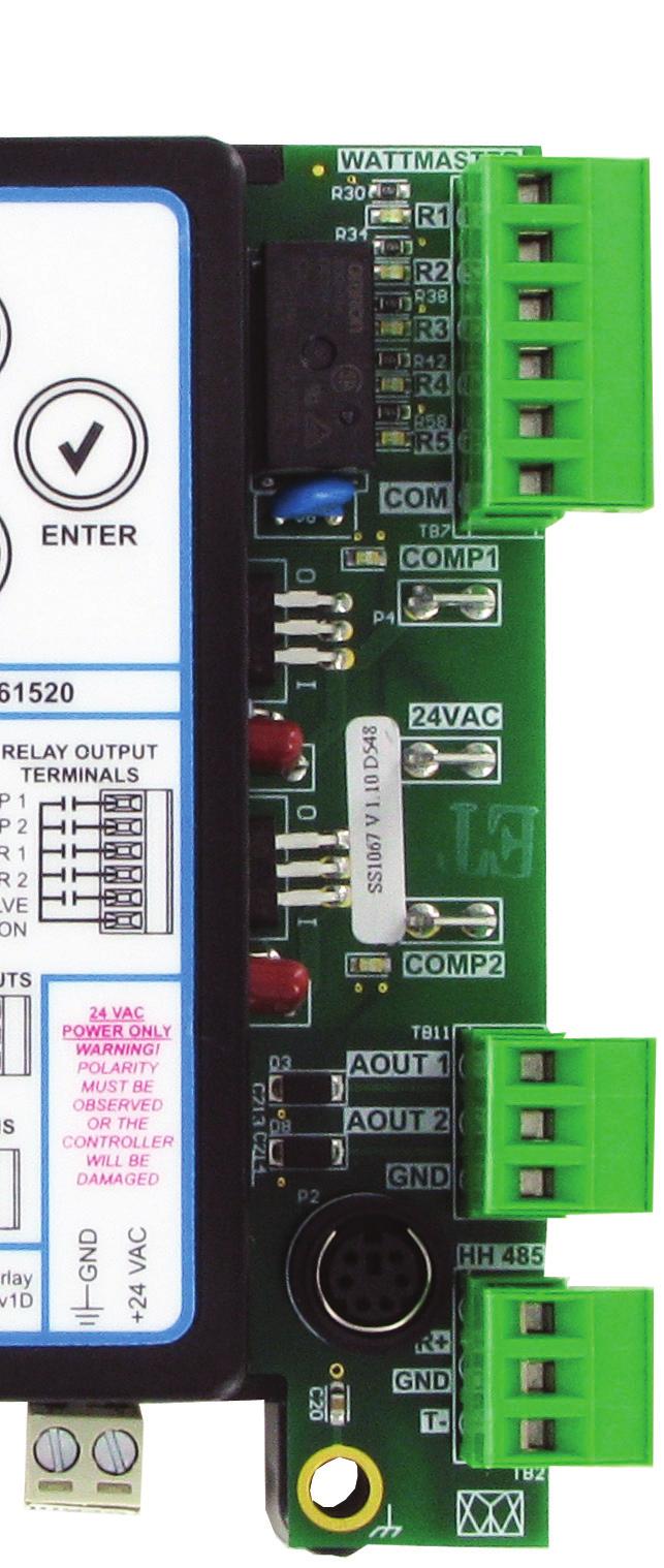
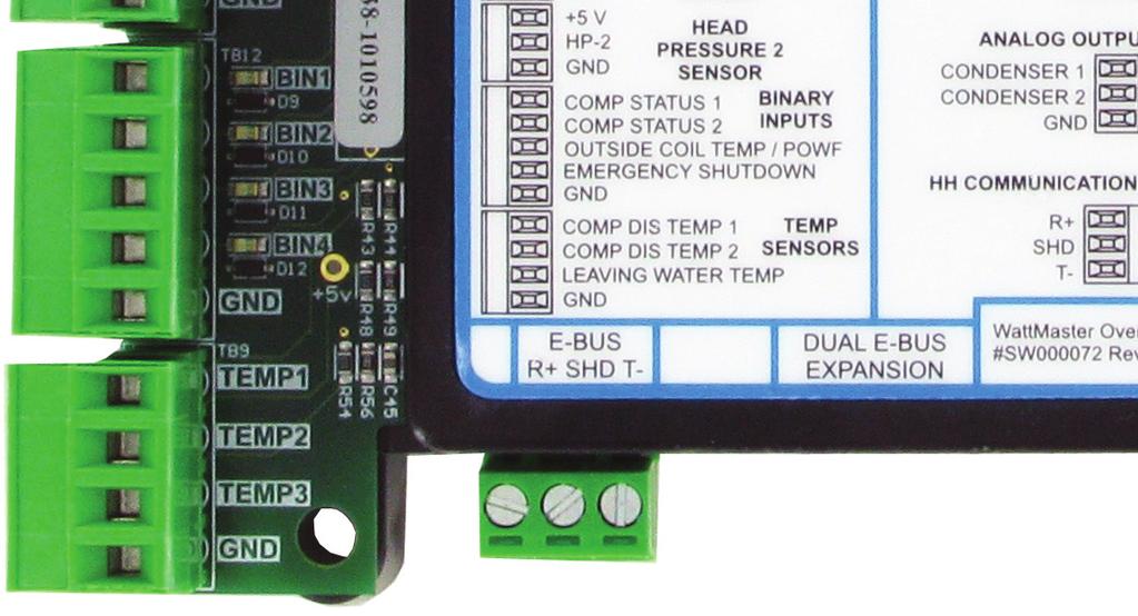
22 TROUBLESHOOTING RSM LED Diagnostics Zone Zone Using RSM LEDs To Verify Operation The RSMs are equipped with LEDs that can be used to verify operation and perform troubleshooting. There are LEDs for communication, operation modes, and diagnostic codes. See Figure 5, below for the LED locations. The LEDs associated with these inputs and outputs allow you to see what is active without using a voltmeter. The LEDs and their uses are as follows: Diagnostic LEDs STATUS - If the software is running, this LED should blink at a rate of 1 blink per second. ALARM (on board) - If the module does not receive communications for more than 1 minute, this LED will light up, the relays will turn off, and the Analog Outputs will go to 0 VDC. ALARM (above LCD display) - This red LED will light up and stay lit when there is an alarm present. The type of alarm will display on the LCD display. The ALARM LED also blinks when the expansion valve is initializing at startup. COMM - Every time the module receives a valid E-BUS request from the VCC-X / VCCX2 Controller, this LED will blink on and then off, signifying that it received a valid request and responded. POWER - This LED will light up to indicate that 24 VAC power has been applied to the controller. Binary Input LEDs BIN1 - This green LED will light up when Compressor Status 1 contact is closed. BIN2 - This green LED will light up when Compressor Status 2 switch is closed. BIN3 - This green LED will light up when the Outside Coil Temperature switch is closed. BIN4 - This green LED will light up when the Emergency Shutdown switch is closed. Relay LEDs RLY1 - RLY5 - These green LEDs will light up when the relays are enabled and will stay lit as long as they are active. Digital Compressor LEDs COMP1 - This green LED will light up when Digital Compressor 1 is unloading. COMP2 - This green LED will light up when Digital Compressor 2 is unloading. RSMD ALARM LED STATUS ALARM COMM POWER LEDs ALARM M UP CHINA VDE 5A30VDC 10A250VAC ~ OMRON G5Q-1A4 DC12V SA RELAY LEDs BINARY INPUT LEDs OE RSMD RSM FOR DIGITAL COMPRESSORS 5 V SUCTION SP-1 PRESSURE 1 SENSOR 5 V HEAD HP-1 PRESSURE 1 SENSOR 5 V SP-2 SUCTION PRESSURE 2 SENSOR 5 V HEAD HP-2 PRESSURE 2 SENSOR COMP STATUS 1 BINARY COMP STATUS 2 INPUTS OUTSIDE COIL TEMP / POWF EMERGENCY SHUTDOWN COMP DIS TEMP 1 TEMP COMP DIS TEMP 2 SENSORS LEAVING WATER TEMP E-BUS MENU DOWN AAON No.: V61520 ENTER RELAY CONTACT RELAY OUTPUT RATING IS 1 AMP TERMINALS 24 VAC COMP 1 COMP 2 CONDENSER 1 CONDENSER 2 REVERSING VALVE COMMON E-BUS ANALOG OUTPUTS CONDENSER 1 CONDENSER 2 WattMaster Overlay # SW Rev1C 24 VAC POWER ONLY WARNING! POLARITY MUST BE OBSERVED OR THE CONTROLLER WILL BE DAMAGED 24 VAC COMP-1 LED COMP-2 LED Figure 5: RSMD LED Locations 22
23 TROUBLESHOOTING OE Suction Pressure Transducer Testing OE Suction Pressure Transducer Testing for R410A Refrigerant The Evaporator Coil Temperature is calculated by converting the Suction Pressure to Temperature. The Suction Pressure is obtained by using the OE Suction Pressure Transducer, which is connected into the Suction Line of the Compressor. Use the voltage column to check the Suction Pressure Transducer while connected to the RSMD Module(s). The VCC-X/VCCX2 and the RSMD Module(s) must be powered for this test. Read voltage with a meter set on DC volts. Place the positive lead from the meter on the SP1/SP2 terminal located on the RSMD Module(s) terminal block. Place the negative lead from the meter on the ground () terminal located adjacent to the SP1/SP2 terminal on the RSMD Module(s) terminal block. Use a refrigerant gauge set and/or an accurate electronic thermometer to measure the temperature or suction line pressure near where the Suction Pressure Transducer is connected to the suction line. Measure the Voltage at the SP1/ SP2 and terminals and compare it to the appropriate chart depending on the refrigerant you are using. If the temperature/ voltage or pressure/voltage readings do not align closely with the chart, your Suction Pressure Transducer is probably defective and will need to be replaced. See the OE Suction Pressure Transducer, Pressure, Temperature, and Voltage Chart for R410A Refrigerant testing. The charts show a temperature range from 20 F to 80 F. For troubleshooting purposes, the DC Voltage readings are also listed with their corresponding temperatures and pressures. Temperature F OE Suction Pressure Transducer Coil Pressure Temperature Voltage Chart for R410A Refrigerant Pressure PSI Signal DC Volts Temperature F Pressure PSI Signal DC Volts Table 3: Coil Pressure/Voltage/Temp for OE Suction Pressure Transducers - R410A Refrigerant 23
24 TROUBLESHOOTING Zone Zone Copeland Discharge Thermistor Temperature Sensor Testing Copeland Discharge Thermistor Temperature Sensor Testing The following sensor voltage and resistance table is provided to aid in checking sensors that appear to be operating incorrectly. Many system operating problems can be traced to incorrect sensor wiring. Be sure all sensors are wired per the wiring diagrams in this manual. If the sensors still do not appear to be operating or reading correctly, check voltage and/or resistance to confirm that the sensor is operating correctly per the table. Please follow the notes and instructions the appear after the chart when checking sensors. Discharge Thermistor Temperature/ Resistance Temp (ºF) Temp (ºC) Resistance (K Ohms) Input (VDC) Discharge Thermistor Temperature/ Resistance Temp (ºF) Temp (ºC) Resistance (K Ohms) Input (VDC) Table 4, cont.: Discharge Thermistor Temperature/ Resistance Thermistor Sensor Testing Instructions Use the resistance column to check the thermistor sensor while disconnected from the controllers (not powered). Use the voltage column to check sensors while connected to powered controllers. Read voltage with meter set on DC volts. Place the - (minus) lead on terminal and the (plus) lead on the sensor input terminal being investigated. If the voltage is above 4.98 VDC, then the sensor or wiring is open. If the voltage is less than 0.38 VDC, then the sensor or wiring is shorted. Table 4: Discharge Thermistor Temperature/ Resistance 24
25 TROUBLESHOOTING Temperature Sensor Testing Leaving Water Temperature Sensor Testing The following sensor voltage and resistance table is provided to aid in checking sensors that appear to be operating incorrectly. Many system operating problems can be traced to incorrect sensor wiring. Be sure all sensors are wired per the wiring diagrams in this manual. If the sensors still do not appear to be operating or reading correctly, check voltage and/or resistance to confirm that the sensor is operating correctly per the tables. Please follow the notes and instructions that appear after the chart when checking sensors. Temperature Resistance Voltage for Type III 10 K Ohm Thermistor Sensors Temp (ºF) Temp (ºC) Resistance (Ohms) Input (VDC) Temperature Resistance Voltage for Type III 10 K Ohm Thermistor Sensors Temp (ºF) Temp (ºC) Resistance (Ohms) Input (VDC) Table 5, cont.: Temperature/Resistance for Type III 10K Ohm Thermistor Sensors Thermistor Sensor Testing Instructions Use the resistance column to check the thermistor sensor while disconnected from the controllers (not powered). Use the voltage column to check sensors while connected to powered controllers. Read voltage with meter set on DC volts. Place the - (minus) lead on terminal and the (plus) lead on the sensor input terminal being investigated. If the voltage is above 4.88 VDC, then the sensor or wiring is open. If the voltage is less than 0.05 VDC, then the sensor or wiring is shorted. Table 5: Temperature/Resistance for Type III 10K Ohm Thermistor Sensors 25
26 TROUBLESHOOTING Zone Head Pressure Transducer Troubleshooting Zone Head Pressure Transducer Troubleshooting If you suspect there is a problem related to the head pressure transducer, measurements can be taken at the HP1 and HP2 terminals. Reference Table 6, below. Head Pressure Transducer Chart Voltage Pressure Voltage Pressure Table 6: Head Pressure Transducer Chart 26
27 TROUBLESHOOTING Notes 27
28 APPENDIX: CONDENSER OPTIONS Default: Two Condenser Operation Two Condenser Operation See Figure 6, below for Two Condenser Operation wiring. Refer to the figures on the following page for Prism2 configuration, Modular Service Tool Screen selection, and HVAC unit application. OE RSMD RSM FOR DIGITAL COMPRESSORS NOTE: ALL RELAY OUTPUTS ARE NORMALLY OPEN AND RATED FOR 24 VAC POWER ONLY - 1 AMP MAXIMUM LOAD 24 VAC ONLY ALARM OE RSMD RSM FOR DIGITAL COMPRESSORS 5 V SUCTION SP-1 PRESSURE 1 SENSOR 5 V HEAD HP-1 PRESSURE 1 SENSOR 5 V SUCTION SP-2 PRESSURE 2 SENSOR 5 V HEAD HP-2 PRESSURE 2 SENSOR COMP STATUS 1 BINARY COMP STATUS 2 INPUTS OUTSIDE COIL TEMP / POWF EMERGENCY SHUTDOWN COMP DIS TEMP 1 TEMP COMP DIS TEMP 2 SENSORS LEAVING WATER TEMP E-BUS R SHD T- M MENU DUAL E-BUS EXPANSION UP DOWN AAON No.: V61520 ENTER RELAY CONTACT RELAY OUTPUT RATING IS 1 AMP TERMINALS 24 VAC COMP 1 COMP 2 CONDENSER 1 CONDENSER 2 REVERSING VALVE COMMON ANALOG OUTPUTS CONDENSER 1 CONDENSER 2 HH COMMUNICATIONS R SHD T- WattMaster Overlay # SW Rev1D 24 VAC POWER ONLY WARNING! POLARITY MUST BE OBSERVED OR THE CONTROLLER WILL BE DAMAGED 24 VAC CHINA 24VAC VDE 5A30VDC 10A250VAC ~ OMRON G5Q-1A4 DC12V SA RLY1 RLY2 RLY3 RLY4 RLY5 COMM UNLOAD 24 VAC UNLOAD COMPRESSOR 1 ENABLE COMPRESSOR 2 ENABLE CONDENSER 1 ENABLE CONDENSER 2 ENABLE REVERSING VALVE DIGITAL COMPRESSOR 1 DIGITAL COMPRESSOR 2 Connects To VCC-X Loop Communications Connector When Used On A Split System. Only Used When Unit Is Controlling Digital Compressors Condenser Signal 1 COM Condenser Signal 2 COM Connect to VCC-X Controller Line Voltage Size Transformer For Correct Total Load. RSMD = 18 VA Figure 6: Default: Two Condenser RSMD Module Wiring 28

29 APPENDIX: CONDENSER OPTIONS Default: Two Condenser Operation Figure 7: Prism 2 Condenser Configuration RSMD Main Configuration Screen #2 - Condenser Options RSMD CONFIGURATION Condenser Options 2 Cond per RSMD USE < or > TO CHANGE Select the 2 Condensers for per RSMD option on the above Hand Held Service Tool Screen. HVAC Unit Application The Two Condenser per RSMD configuration is used with the following HVAC units: D-BOX Ton C-BOX Ton B-BOX 29
30 APPENDIX: CONDENSER OPTIONS Single Condenser Per Module Single Condenser Per Module See Figure 8, below for Single Condenser Per Module wiring. Refer to the figures on the following page for Prism 2 configuration, Modular Service Tool Screen selection, and HVAC unit application. OE RSMD RSM FOR DIGITAL COMPRESSORS NOTE: ALL RELAY OUTPUTS ARE NORMALLY OPEN AND RATED FOR 24 VAC POWER ONLY - 1 AMP MAXIMUM LOAD ALARM OE RSMD RSM FOR DIGITAL COMPRESSORS 5 V SUCTION SP-1 PRESSURE 1 SENSOR 5 V HEAD HP-1 PRESSURE 1 SENSOR 5 V SUCTION SP-2 PRESSURE 2 SENSOR 5 V HEAD HP-2 PRESSURE 2 SENSOR COMP STATUS 1 BINARY COMP STATUS 2 INPUTS OUTSIDE COIL TEMP / POWF EMERGENCY SHUTDOWN COMP DIS TEMP 1 TEMP COMP DIS TEMP 2 SENSORS LEAVING WATER TEMP E-BUS R SHD T- M MENU DUAL E-BUS EXPANSION UP DOWN AAON No.: V61520 ENTER RELAY CONTACT RELAY OUTPUT RATING IS 1 AMP TERMINALS 24 VAC COMP 1 COMP 2 CONDENSER 1 CONDENSER 2 REVERSING VALVE COMMON ANALOG OUTPUTS CONDENSER 1 CONDENSER 2 HH COMMUNICATIONS R SHD T- WattMaster Overlay # SW Rev1D 24 VAC POWER ONLY WARNING! POLARITY MUST BE OBSERVED OR THE CONTROLLER WILL BE DAMAGED 24 VAC CHINA 24VAC VDE 5A30VDC 10A250VAC ~ OMRON G5Q-1A4 DC12V SA RLY1 RLY2 RLY3 RLY4 RLY5 COMM UNLOAD 24 VAC UNLOAD 24 VAC ONLY COMPRESSOR 1 ENABLE COMPRESSOR 2 ENABLE CONDENSER 1 ENABLE NOT USED REVERSING VALVE DIGITAL COMPRESSOR 1 DIGITAL COMPRESSOR 2 Connects To VCC-X Loop Communications Connector When Used On A Split System. Only Used When Unit Is Controlling Digital Compressors Condenser Signal 1 COM Connect to VCC-X Controller Line Voltage Size Transformer For Correct Total Load. RSMD = 18 VA Figure 8: Single Condenser Per RSMD Module Wiring 30

31 APPENDIX: CONDENSER OPTIONS Single Condenser Per Module Figure 9: Prism 2 Condenser Configuration RSMD Main Configuration Screen #2 - Condenser Options RSMD CONFIGURATION Condenser Options 1 Cond for 1 RSMD USE < or > TO CHANGE Select the 1 Condenser for 1 RSMD option on the above Hand Held Service Tool Screen. HVAC Unit Application The One Condenser per RSMD configuration is used with the following HVAC units: B-BOX Air to Air Heat Pump B-BOX WSHP C-BOX Ton C-BOX Air to Air Heat Pump C-BOX WSHP 31
32 APPENDIX: CONDENSER OPTIONS Single Condenser Per Two Modules Single Condenser Per 2 Modules See Figure 10, below for Single Condenser Per 2 Modules wiring. Refer to the figures on the following page for Prism 2 configuration, Modular Service Tool Screen selection, and HVAC unit application. OE RSMD RSM FOR DIGITAL COMPRESSORS NOTE: ALL RELAY OUTPUTS ARE NORMALLY OPEN AND RATED FOR 24 VAC POWER ONLY - 1 AMP MAXIMUM LOAD ALARM OE RSMD RSM FOR DIGITAL COMPRESSORS 5 V SUCTION SP-1 PRESSURE 1 SENSOR 5 V HEAD HP-1 PRESSURE 1 SENSOR 5 V SUCTION SP-2 PRESSURE 2 SENSOR 5 V HEAD HP-2 PRESSURE 2 SENSOR COMP STATUS 1 BINARY COMP STATUS 2 INPUTS OUTSIDE COIL TEMP / POWF EMERGENCY SHUTDOWN COMP DIS TEMP 1 TEMP COMP DIS TEMP 2 SENSORS LEAVING WATER TEMP E-BUS R SHD T- M MENU DUAL E-BUS EXPANSION UP DOWN AAON No.: V61520 ENTER RELAY CONTACT RELAY OUTPUT RATING IS 1 AMP TERMINALS 24 VAC COMP 1 COMP 2 CONDENSER 1 CONDENSER 2 REVERSING VALVE COMMON ANALOG OUTPUTS CONDENSER 1 CONDENSER 2 HH COMMUNICATIONS R SHD T- WattMaster Overlay # SW Rev1D 24 VAC POWER ONLY WARNING! POLARITY MUST BE OBSERVED OR THE CONTROLLER WILL BE DAMAGED 24 VAC CHINA 24VAC VDE 5A30VDC 10A250VAC ~ OMRON G5Q-1A4 DC12V SA RLY1 RLY2 RLY3 RLY4 RLY5 COMM UNLOAD 24 VAC UNLOAD 24 VAC ONLY COMPRESSOR 1 ENABLE COMPRESSOR 2 ENABLE CONDENSER 1 ENABLE NOT USED REVERSING VALVE DIGITAL COMPRESSOR 1 DIGITAL COMPRESSOR 2 Connects To VCC-X Loop Communications Connector When Used On A Split System. Not Used on 2nd Module & 4th Module Only Used When Unit Is Controlling Digital Compressors Condenser Signal 1 COM Not Used on 2nd Module & 4th Module NOTE: If There Are 4 Modules, 1 & 3 Match and 2 & 4 Match. Connect to VCC-X Controller Line Voltage Size Transformer For Correct Total Load. RSMD = 18 VA Figure 10: Single Condenser Per 2 RSMD Modules Wiring 32

33 APPENDIX: CONDENSER OPTIONS Single Condenser Per Two Modules Figure 11: Prism 2 Condenser Configuration RSMD Main Configuration Screen #2 - Condenser Options RSMD CONFIGURATION Condenser Options 1 Cond for 2 RSMDs USE < or > TO CHANGE Select the 1 Condenser for 2 RSMDs option on the above Hand Held Service Tool Screen. HVAC Unit Application The One Condenser per Two RSMDs configuration is used with the following HVAC units: RLA BOX RLB BOX RLE BOX 33
34 APPENDIX: CONDENSER OPTIONS Single Condenser For Three Modules Single Condenser for 3 Modules See Figure 12, below for Single Condenser for 3 Modules wiring. Refer to the figures on the following page for Prism2 configuration, Modular Service Tool Screen selection, and HVAC unit application. OE RSMD RSM FOR DIGITAL COMPRESSORS NOTE: ALL RELAY OUTPUTS ARE NORMALLY OPEN AND RATED FOR 24 VAC POWER ONLY - 1 AMP MAXIMUM LOAD ALARM OE RSMD RSM FOR DIGITAL COMPRESSORS 5 V SUCTION SP-1 PRESSURE 1 SENSOR 5 V HEAD HP-1 PRESSURE 1 SENSOR 5 V SUCTION SP-2 PRESSURE 2 SENSOR 5 V HEAD HP-2 PRESSURE 2 SENSOR COMP STATUS 1 BINARY COMP STATUS 2 INPUTS OUTSIDE COIL TEMP / POWF EMERGENCY SHUTDOWN COMP DIS TEMP 1 TEMP COMP DIS TEMP 2 SENSORS LEAVING WATER TEMP E-BUS R SHD T- M MENU DUAL E-BUS EXPANSION UP DOWN AAON No.: V61520 ENTER RELAY CONTACT RELAY OUTPUT RATING IS 1 AMP TERMINALS 24 VAC COMP 1 COMP 2 CONDENSER 1 CONDENSER 2 REVERSING VALVE COMMON ANALOG OUTPUTS CONDENSER 1 CONDENSER 2 HH COMMUNICATIONS R SHD T- WattMaster Overlay # SW Rev1D 24 VAC POWER ONLY WARNING! POLARITY MUST BE OBSERVED OR THE CONTROLLER WILL BE DAMAGED 24 VAC CHINA 24VAC VDE 5A30VDC 10A250VAC ~ OMRON G5Q-1A4 DC12V SA RLY1 RLY2 RLY3 RLY4 RLY5 COMM UNLOAD 24 VAC UNLOAD 24 VAC ONLY COMPRESSOR 1 ENABLE COMPRESSOR 2 ENABLE CONDENSER 1 ENABLE NOT USED REVERSING VALVE DIGITAL COMPRESSOR 1 DIGITAL COMPRESSOR 2 Connects To VCC-X Loop Communications Connector When Used On A Split System. Only Used on 1st Module. Not Used on 2nd & 3rd. Only Used When Unit Is Controlling Digital Compressors Condenser Signal 1 COM Only Used on 1st Module. Not Used on 2nd & 3rd. Connect to VCC-X Controller Line Voltage Size Transformer For Correct Total Load. RSMD = 18 VA Figure 12: Single Condenser for 3 RSMD Modules Wiring 34
35 APPENDIX: CONDENSER OPTIONS Single Condenser For Three Modules Figure 13: Prism 2 Condenser Configuration RSMD Main Configuration Screen #2 - Condenser Options RSMD CONFIGURATION Condenser Options 1 Cond for 3 RSMDs USE < or > TO CHANGE HVAC Unit Application The One Condenser per Three RSMDs configuration is used with the following HVAC units: RLC BOX RLD BOX Select the 1 Condenser for 3 RSMDs option on the above Hand Held Service Tool Screen. 35
36 APPENDIX: CONDENSER OPTIONS Two Condensers Per Two Modules A1/B1 and A2/B2 Condenser Fans See Figure 14, below and Figure 15 on the facing page for Two Condensers for 2 Modules wiring. Refer to the figures on page 38 for Prism 2 configuration, Modular Service Tool Screen selection, and HVAC unit application. OE RSMD A1 / B1 Address 1 NOTE: ALL RELAY OUTPUTS ARE NORMALLY OPEN AND RATED FOR 24 VAC POWER ONLY - 1 AMP MAXIMUM LOAD 24 VAC ONLY ALARM OE RSMD RSM FOR DIGITAL COMPRESSORS 5 V SUCTION SP-1 PRESSURE 1 SENSOR 5 V HEAD HP-1 PRESSURE 1 SENSOR 5 V SUCTION SP-2 PRESSURE 2 SENSOR 5 V HEAD HP-2 PRESSURE 2 SENSOR COMP STATUS 1 BINARY COMP STATUS 2 INPUTS OUTSIDE COIL TEMP / POWF EMERGENCY SHUTDOWN COMP DIS TEMP 1 TEMP COMP DIS TEMP 2 SENSORS LEAVING WATER TEMP E-BUS R SHD T- M MENU DUAL E-BUS EXPANSION UP DOWN AAON No.: V61520 ENTER RELAY CONTACT RELAY OUTPUT RATING IS 1 AMP TERMINALS 24 VAC COMP 1 COMP 2 CONDENSER 1 CONDENSER 2 REVERSING VALVE COMMON ANALOG OUTPUTS CONDENSER 1 CONDENSER 2 HH COMMUNICATIONS R SHD T- WattMaster Overlay # SW Rev1D 24 VAC POWER ONLY WARNING! POLARITY MUST BE OBSERVED OR THE CONTROLLER WILL BE DAMAGED 24 VAC CHINA 24VAC VDE 5A30VDC 10A250VAC ~ OMRON G5Q-1A4 DC12V SA RLY1 RLY2 RLY3 RLY4 RLY5 COMM UNLOAD 24 VAC UNLOAD COMPRESSOR A1 ENABLE COMPRESSOR A2 ENABLE CONDENSER A1 / B1 ENABLE CONDENSER A2 / B2 ENABLE REVERSING VALVE A1 / B1 DIGITAL COMPRESSOR 1 DIGITAL COMPRESSOR 2 Connects To VCC-X Loop Communications Connector When Used On A Split System. Only Used When Unit Is Controlling Digital Compressors Condenser Signal A1 / B1 COM Condenser Signal A2 / B2 COM Connect to VCC-X Controller Line Voltage Size Transformer For Correct Total Load. RSMD = 18 VA Figure 14: A1/ B1 Wiring 36
37 APPENDIX: CONDENSER OPTIONS Two Condensers Per Two Modules OE RSMD A2 / B2 Address 2 NOTE: ALL RELAY OUTPUTS ARE NORMALLY OPEN AND RATED FOR 24 VAC POWER ONLY - 1 AMP MAXIMUM LOAD ALARM OE RSMD RSM FOR DIGITAL COMPRESSORS 5 V SUCTION SP-1 PRESSURE 1 SENSOR 5 V HEAD HP-1 PRESSURE 1 SENSOR 5 V SUCTION SP-2 PRESSURE 2 SENSOR 5 V HEAD HP-2 PRESSURE 2 SENSOR COMP STATUS 1 BINARY COMP STATUS 2 INPUTS OUTSIDE COIL TEMP / POWF EMERGENCY SHUTDOWN COMP DIS TEMP 1 TEMP COMP DIS TEMP 2 SENSORS LEAVING WATER TEMP E-BUS R SHD T- M MENU DUAL E-BUS EXPANSION UP DOWN AAON No.: V61520 ENTER RELAY CONTACT RELAY OUTPUT RATING IS 1 AMP TERMINALS 24 VAC COMP 1 COMP 2 CONDENSER 1 CONDENSER 2 REVERSING VALVE COMMON ANALOG OUTPUTS CONDENSER 1 CONDENSER 2 HH COMMUNICATIONS R SHD T- WattMaster Overlay # SW Rev1D 24 VAC POWER ONLY WARNING! POLARITY MUST BE OBSERVED OR THE CONTROLLER WILL BE DAMAGED 24 VAC CHINA 24VAC VDE 5A30VDC 10A250VAC ~ OMRON G5Q-1A4 DC12V SA RLY1 RLY2 RLY3 RLY4 RLY5 COMM UNLOAD 24 VAC UNLOAD 24 VAC ONLY COMPRESSOR B1 ENABLE COMPRESSOR B2 ENABLE NOT USED NOT USED REVERSING VALVE A2 / B2 DIGITAL COMPRESSOR B1 DIGITAL COMPRESSOR B2 Connects To VCC-X Loop Communications Connector When Used On A Split System. Only Used When Unit Is Controlling Digital Compressors Connect to VCC-X Controller Line Voltage Size Transformer For Correct Total Load. RSMD = 18 VA Figure 15: A2 / B2 Wiring 37

38 APPENDIX: CONDENSER OPTIONS Two Condensers Per Two Modules Figure 16: Prism 2 Condenser Configuration RSMD Main Configuration Screen #2 - Condenser Options RSMD CONFIGURATION Condenser Options 2 Cond for 2 RSMDs USE < or > TO CHANGE Select the 2 Condensers for 2 RSMDs option on the above Hand Held Service Tool Screen. HVAC Unit Application The Two Condensers per Two RSMDs configuration is used with the following HVAC units: D-BOX Ton D-BOX Air to Air Heat Pump D-BOX WSHP 38
Factory Packaged Controls. OE (AAON Part No. V12090) MODGAS-X Controller Field Technical Guide
 MODGAS-X Controller Field Technical Guide") Factory Packaged Controls OE377-26-00058 (AAON Part No. V12090) MODGAS-X Controller Table of Contents GENERAL INFORMATION... 3 Overview...3 Features...3 INSTALLATION & WIRING... 4 Supply Air Temperature
Factory Packaged Controls OE377-26-00058 (AAON Part No. V12090) MODGAS-X Controller Table of Contents GENERAL INFORMATION... 3 Overview...3 Features...3 INSTALLATION & WIRING... 4 Supply Air Temperature
Application Engineering
 Application Engineering March 2011 Copeland Digital Compressor Controller Introduction The Digital Compressor Controller is the electronics interface between the Copeland Scroll Digital compressor or the
HP21 SERVICE SUPPLEMENT UNIT INFORMATION. TSC6 Two-Speed Control
 SERVICE UNIT INFORMATION SUPPLEMENT HP21 Corp. 9426 L10 Litho U.S.A. All HP21-4 and -5 units (single and three phase) are equipped with a TSC6 two-speed control. The TSC6 (A14) two-speed control contains
Application Engineering
 Application Engineering February, 2009 Copeland Digital Compressor Controller Introduction The Digital Compressor Controller is the electronics interface between the Copeland Scroll Digital Compressor
ZIP Economizer Fault Detection and Diagnostics (FDD) Table
 Table") Fault Detection and Diagnostics (FDD) Table Fault Detection Problem Diagnostic ction (in addition to alarm stored / transmitted) Potential Cause C Fault Code OT sensor predetermined range O damper returns
Fault Detection and Diagnostics (FDD) Table Fault Detection Problem Diagnostic ction (in addition to alarm stored / transmitted) Potential Cause C Fault Code OT sensor predetermined range O damper returns
PCT-3001 plus. Display LCD
 PCT3 plus DIGITAL PRESSURE CONTROLLER FOR COOLING PLANTS DESCRIPTION Pressure controller for refrigeration systems capable to control suction (compressors) and discharge (fans) pressures. It is possible
Application Guide Paragon TM Control Module (PCM) Slide Valve and Protection Control 10/25/2016 Rev 1. Carlyle Controller Part No.
 Slide Valve and Protection Control 10/25/2016 Rev 1. Carlyle Controller Part No.") Application Guide 575-012 Paragon TM Control Module (PCM) Slide Valve and Protection Control 10/25/2016 Rev 1 Carlyle Controller Part No. 2BSB000928 1 General Description The PCM is part of Paragon Compressor
Application Guide 575-012 Paragon TM Control Module (PCM) Slide Valve and Protection Control 10/25/2016 Rev 1 Carlyle Controller Part No. 2BSB000928 1 General Description The PCM is part of Paragon Compressor
Vission 20/20 micro-controller. Operation and service manual
 Vission 20/20 micro-controller Operation and service manual Section Title Table of Contents Section Number How To Use This Manual...TOC-8 Section 1 Operational Flow Charts Requirements to Start Compressor...1-1
Engineering Bulletin. IntelliPak RTM (Rooftop Module, 1U48) Subject: Generic Building Automation System (GBAS, UCM Module, 1U51)
 Subject: Generic Building Automation System (GBAS, UCM Module, 1U51)") Engineering Bulletin IntelliPak RTM (Rooftop Module, 1U48) Subject: Generic Building Automation System (GBAS, UCM Module, 1U51) Issued By: Clarksville Marketing and Sales Support Order No. UN-PRB001-EN
Engineering Bulletin IntelliPak RTM (Rooftop Module, 1U48) Subject: Generic Building Automation System (GBAS, UCM Module, 1U51) Issued By: Clarksville Marketing and Sales Support Order No. UN-PRB001-EN
P445 Series Electronic Lube Oil Control
 FANs 125, 121 s Section P Product/Technical Bulletin P445 Issue Date 0100 P445 Series Electronic Lube Oil The P445 Series Electronic Lube Oil is designed for use on refrigeration compressors equipped with
Fault Codes. J control
 J control Timer Temp Fault Codes 12 11 10 9 8 7 6 5 4 3 2 1 30 29 28 27 26 25 24 23 22 21 20 Enter unit inspection mode by pushing the UP and DOWN buttons simultaneously for two seconds. Ensure that the
LG Air Conditioning Universal & Multi Split Fault Codes Sheet. Universal and Multi Split Units
 Universal and Multi Split Units If there is a fault on any LG Universal or Multi unit, a two digit number will appear on the remote controllers led display. If the unit does not have a remote controller
Vission 20/20 micro-controller. Operation and service manual Version 2.6
 Vission 20/20 micro-controller Operation and service manual Version 2.6 Important Message READ CAREFULLY BEFORE OPERATING YOUR COMPRESSOR. The following instructions have been prepared to assist in operation
HGM1780. Automatic Genset Controller USER MANUAL. Smartgen Technology
 HGM1780 Automatic Genset Controller USER MANUAL Smartgen Technology Smartgen Technology Co., Ltd No. 28 Jinsuo Road Zhengzhou Henan Province P. R. China Tel: 0086-371-67988888/67981888 0086-371-67991553/67992951
PCT-3000 plus DIGITAL PRESSURE CONTROLLER FOR COOLING PLANTS
 PCT plus DIGITAL PRESSURE CONTROLLER FOR COOLING PLANTS Ver. DESCRIPTION The PCT plus is a pressure controller for refrigeration plants that require control in their suction and discharge stages. With
CURTIS TOLEDO. AF Series Compressors VS models with VFD WARNING
 AUGUST, 2004 REV.A CURTIS TOLEDO OPERATOR S MANUAL SUPPLEMENT AF Series Compressors VS models with VFD WARNING Personal injury and/or equipment damage will result by failing to pay attention to the vital
Modulating Furnace Information. Warning on Meter Setting - Read First!
 Modulating Furnace Information Pressure Transducer Pressure DC Volts 0.00" 0.25 0.20" 0.63 0.25" 0.72 0.30" 0.82 0.35" 0.91 0.40" 1.00 0.45" 1.09 0.50" 1.19 0.55" 1.28 0.60" 1.38 0.65" 1.47 0.70" 1.56
Subject Underhood G System Error Codes and Symptoms System or Parts affected
 System or Parts affected Index Underhood70G (V90Gxxx) System or Parts affected... 1 Overview... 1 Identifying your System... 1 Retrieving Logged Error Messages... 1 Error Messages... 3 Error Message Table...
Application Engineering Europe
 Date of last update: Feb-12 Ref: D7.8.4/0112-0212/E Application Engineering Europe CORESENSE DIAGNOSTICS FOR STREAM REFRIGERATION COMPRESSORS 1/17 1 Introduction CoreSense is an ingredient brand name for
Copeland Screw TM Compressors
 Copeland Screw TM Compressors Mechanical Guidelines for SHL & SHM Models using ESC-201 Control System Contents: Start-Up Procedure Operating Specifications Maintenance Trouble Shooting Guidelines Start-up
SE8300 Series Installation Guide 24 Vac Low Voltage
 Installation Guide 24 Vac Voltage mercial and Hotel/Lodging HVAC Fan Coil Applications CONTENTS Installation 2 Configurable BI/UI Universal Inputs Overview 3 Setup Screen Display 3 Terminal Identification
BRIVIS DUCTED INVERTER SERVICE MANUAL DRCi
 BRIVIS DUCTED INVERTER SERVICE MANUAL DRCi 1 TABLE OF CONTENTS TABLE OF CONTENTS... 2 IMPORTANT NOTE... 3 FAULT FINDING AND DIAGNOSTICS... 3 ABBREVIATIONS... 3 PCB S... 4 OUTDOOR MAIN PCB... 4 INDOOR PCB...
Metasys Zoning Package Installation
 Technical Bulletin Issue Date August 28, 2002 Metasys Zoning Package Installation Metasys Zoning Package Installation...2 Introduction... 2 Key Concepts... 3 Installation Overview... 3 Metasys Zoning Package
CORESENSE DIAGNOSTICS FOR STREAM REFRIGERATION COMPRESSORS
 Date of last update: Apr-15 Ref: D7.8.4/0112-0415/E Application Engineering Europe CORESENSE DIAGNOSTICS FOR STREAM REFRIGERATION COMPRESSORS CoreSense Diagnostics for Stream Refrigeration Compressors...
Spartan Controls Millennium Compressor Control Panel Operating Philosophy
 Project: Stock Revision 1 Page 1 Spartan Controls Millennium Compressor Control Panel Operating Philosophy Location: Stock Customer references: Vendor: Vendor document: Spartan Controls Ltd. Operating
EcoNet and Flash Codes
 The error codes below will be displayed at the EcoNet Control Center under Service window / Current Faults or in the Fault History and will be time & date stamped. VSODC (Variable Speed Outdoor Unit Control
BIGLA30-T/BIELA14-T Event Codes Quick Reference EXPLANATION CORRECTIVE ACTION PARTS TO CARRY ON SERVICE CALL
 E13 TEMPERATURE PROBE FAILURE E16 HIGH LIMIT 1 EXCEEDED A. TEMP Probe reading out of range. B. Bad Connection. C. Problem with the temperatur e measuring circuitry including the probe. High limit temperature
LG Air conditioning CAC and Multi Split unit Fault code sheet Universal and Multi Split Units
 Universal and Multi Split Units If there is fault on any LG universal or multi unit a two digit number will appear on the remote controllers led display. If the unit does not have a remote controller the
MICROPROCESSOR BASED CONTROLLER
 MICROPROCESSOR BASED CONTROLLER Electronic Controller for Bus HVAC Front Box Units FrontAIRE II SERVICE MANUAL TK 53337-3-MM (Rev. 0, 09/06) 2006 THERMO KING Table of contents 1. General Information...
MODEL 422 Submersible Pump Controller
 MODEL 422 Submersible Pump Controller Monitors True Motor Power (volts x current x power factor) Detects Motor Overload or Underload Operates on 120 or 240VAC, Single-phase or 3-phase Built-in Trip and
HWP Protection Board
 February 2009 HWP Protection Board Features and Operation This board provides the system protection features necessary to keep our HWP (Water Sourced Heat Pump) units safe in the instances when they are
PF3100 TROUBLESHOOTING SOLUTIONS TO COMMON PROBLEMS. v1.1 Revised Nov 29, 2016
 PF3100 TROUBLESHOOTING SOLUTIONS TO COMMON PROBLEMS v1.1 Revised Table of Contents 1 Common Alarms and Warnings... 1 2 Common Issues... 6 2.1 Communication problems... 6 2.1.1 Controller communication
Model No. DFC-X Support DIRECT FIRED DIGITAL TEMPERATURE CONTROL INSTALLATION, OPERATION, AND MAINTENANCE MANUAL
 Model No. DFC-X Support 877-351-4702 DIRECT FIRED DIGITAL TEMPERATURE CONTROL INSTALLATION, OPERATION, AND MAINTENANCE MANUAL This manual covers the following products: DFC-X TS-01 DFTD RDU DAT-12 PWM-10V
Service Facts. WARNING: HAZARdOuS VOLTAGe - disconnect POWeR and discharge 4TTX6048-SF-1K. ComfortLink II System Cooling 4TTX6048C1000A.
 Service Facts ComfortLink II System Cooling 4TTX6048C1000A 4TTX6048C1000A 230/1/60 28 45 CLIMATUFF - SCROLL 1-2 230/1/60 21.2-96 PROPELLER 27.6-1 DIRECT - 1 4600/4600 1-1/5 820 200/230/1/60 1.10 SPINE
Flight Systems. Replacement for KASSEC DESCRIPTION
 DESCRIPTION The is a universal generator controller that will start, stop, and provide engine protection for most generators. Universal replacement for both the 90353 and 90354 KASSEC Compatible with most
Service Facts. WARNING: HAZARDOUS VOLTAGE - DISCONNECT POWER and DISCHARGE 4TTZ0036B-SF-1B. ComfortLink II System Cooling 4TTZ0036B1000A CAUTION
 Service Facts ComfortLink II System Cooling 4TTZ0036B1000A 4TTZ0036B1000A 208/230/1/60 19 30 CLIMATUFF 2-2 208/230/1/60 13.2-60.0 YES YES YES PROPELLER 27.6-1 DIRECT - 2 4450/3190 1-1/3 707/493 200/230/1/60
Product Manual. Part Number: MVP-193 Mefi-6 ECU Revision: 1.0
 Product Manual Part Number: MVP-193 Mefi-6 ECU Revision: 1.0 Copyright Controls, Inc. P.O. Box 368 Sharon Center, OH 44274 Phone 330.239.4345 Fax 330.239.2845 www.controlsinc.com TABLE OF CONTENTS PRIOR
Section 55 Chapter 6
 Section 55 Chapter 6 REMOTE HYDRAULICS CONTROLLER Calibration and Fault Codes 6-12880NH TABLE OF CONTENTS REMOTE HYDRAULICS CONTROLLER CALIBRATION... 55-5 Requirements For Calibration... 55-5 Aux Set Main
VC-4820 Programmable DC-DC Converter with Battery Charger function USER'S MANUAL
 1. INTRODUCTION VC-4820 Programmable DC-DC Converter with Battery Charger function USER'S MANUAL This MCU controlled Step Down DC-DC Converter has a digitally adjustable output in 0.2V increments. This
Hardware Installation. Tracer AH541 Version 2 Air-Handler Controller CNT-SVN02B-EN
 Hardware Installation Tracer AH541 Version 2 Air-Handler Controller CNT-SVN02B-EN Hardware Installation Tracer AH541 Version 2 Air-Handler Controller CNT-SVN02B-EN February 2004 CNT-SVN02B-EN Tracer AH541
HS Refrigeration Screw Compressor Troubleshooting Guidelines. SG March 2014
 HS Refrigeration Screw Compressor Troubleshooting Guidelines SG-0003-01 March 2014 Refrigeration Screw Compressor Troubleshooting Guidelines SG-0003-01 March 2014 BITZER Screw Compressors CS High Temp
DFC-1 STANDARD TEMPERATURE CONTROL. DFC-2 TEMPERATURE CONTROL w/ INTEGRAL 40 F-90 F SELECTOR DFTD TEMPERATURE SELECTION DIAL DFTS TEMPERATURE SENSOR
 24 Volt AC input Built in 15 second low fire start timer 0-24 Volt DC modulating output Remote temperature selection Calibration trim pot Rated for -40 F (-40 C) DFC-1 STANDARD TEMPERATURE CONTROL DFC-2
OPERATING MANUAL Digital Diesel Control Remote control panel for WhisperPower generator sets
 Art. nr. 40200261 OPERATING MANUAL Digital Diesel Control Remote control panel for WhisperPower generator sets WHISPERPOWER BV Kelvinlaan 82 9207 JB Drachten Netherlands Tel.: +31-512-571550 Fax.: +31-512-571599
START-UP CHECKLIST. Date: Job Name: Customer Name: Address: City: State: Zip: Model Number: Serial Number: Qualified Start-up Technician:
 START-UP INSTRUCTION OPTIMUM 36000 To 72000 BTU S PACKAGE UNITS 3 To 6 Ton START-UP CHECKLIST Date: Job Name: Customer Name: Address: City: State: Zip: Model Number: Serial Number: Qualified Start-up Technician:
REVISION HISTORY REVISION HISTORY
 FILTER CONTROLLER REVISION HISTORY Filter Flush Controller forms part of the Netafim range of filtration controllers all designed to make filteration more reliable and economical.. Contact any of the Netafim
DIN Rail UPS Model: DIN-UPS Installation/Operation Manual
 DIN Rail UPS Model: DIN-UPS 24-10 Installation/Operation Manual Table of Contents Section Page Section Page Quick Start 2 1) General Information 4 Materials Provided 4 Optional Equipment 4 2) Safety Information
Supersedes CL2 (512) Form CL2 (615) STARTUP CHECKLIST PHONE: CUSTOMER ORDER NO: JCI TEL NO: JCI ORDER NO: JCI CONTRACT NO:
 Form CL2 (615) STARTUP CHECKLIST PHONE: CUSTOMER ORDER NO: JCI TEL NO: JCI ORDER NO: JCI CONTRACT NO:") YMC 2 - MOD A STARTUP CHECKLIST Supersedes 160.78-CL2 (512) Form 160.78-CL2 (615) STARTUP CHECKLIST CUSTOMER: JOB NAME: ADDRESS: LOCATION: PHONE: CUSTOMER ORDER NO: JCI TEL NO: JCI ORDER NO: JCI CONTRACT
YMC 2 - MOD A STARTUP CHECKLIST Supersedes 160.78-CL2 (512) Form 160.78-CL2 (615) STARTUP CHECKLIST CUSTOMER: JOB NAME: ADDRESS: LOCATION: PHONE: CUSTOMER ORDER NO: JCI TEL NO: JCI ORDER NO: JCI CONTRACT
Service Facts. WARNING: HAZARdOuS VOLTAGe - disconnect POWeR and discharge 4TWX6024-SF-1K. ComfortLink II System Heat Pump 4TWX6024C1000A.
 Service Facts ComfortLink II System Heat Pump 4TWX6024C1000A 4TWX6024C1000A 230/1/60 13 20 CLIMATUFF - SCROLL 1-2 230/1/60 10.3-52 PROPELLER 23-1 DIRECT - 1 2300/2300 1-1/8 825 200/230/1/60 0.70 SPINE
INSTALLATION GUIDE. FCC ID NOTICE
 REV.5 RS. ADVANCED REMOTE STARTER INSTALLATION GUIDE www.security.soundstream.com FCC ID NOTICE This device complies with Part 5 of the FCC rules. Operation is subject to the following conditions:. This
START-UP CHECKLIST. Date: Job Name: Customer Name: Address: City: State: Zip: Model Number: Serial Number: Qualified Start-up Technician:
 START-UP INSTRUCTION START-UP CHECKLIST SERIES 5 36000 To 72000 BTU S PACKAGE UNITS 3 To 6 Ton Date: _ Job Name: Customer Name: Address: City: State: Zip: Model Number: Serial Number: Qualified Start-up
MATRIX LLC LEVEL CONTROL PANEL
 MATRIX LLC LEVEL CONTROL PANEL Installation Operation Maintenance Manual 1-26-09 REV-0.3 1 INDEX Introduction. 3 Product Configurations..... 4 I/O Descriptions. 8 Operation o Intercooler, Accumulator,
SERVICE MANUAL (DOMESTIC & INTERNATIONAL)
") SERVICE MANUAL (DOMESTIC & INTERNATIONAL) DUAL TECHNOLOGY FINISHER MODEL 1960 & 1980 SERIES Lincoln Foodservice Products, LLC 1111 North Hadley Road Fort Wayne, Indiana 46804 United States of America Telephone:
SERVICE MANUAL (DOMESTIC & INTERNATIONAL) DUAL TECHNOLOGY FINISHER MODEL 1960 & 1980 SERIES Lincoln Foodservice Products, LLC 1111 North Hadley Road Fort Wayne, Indiana 46804 United States of America Telephone:
2 WAY REMOTE STARTER & ALARM SYSTEM INSTALLATION GUIDE FCC ID NOTICE
 REV. ARS. WAY REMOTE STARTER & ALARM SYSTEM INSTALLATION GUIDE FCC ID NOTICE This device complies with Part 5 of the FCC rules. Operation is subject to the following conditions:. This device may not cause
TECHNICAL BROCHURE BSPDDRIVE. Aquavar SPD (Single Pump Drive) SIMPLEX VARIABLE SPEED PUMP CONTROLLER FOR SUBMERSIBLE AND CENTRIFUGAL PUMPS
 SIMPLEX VARIABLE SPEED PUMP CONTROLLER FOR SUBMERSIBLE AND CENTRIFUGAL PUMPS") TECHNICAL BROCHURE BSPDDRIVE C U L US Aquavar SPD (Single Pump Drive) SIMPLEX VARIABLE SPEED PUMP CONTROLLER FOR SUBMERSIBLE AND CENTRIFUGAL PUMPS Aquavar SPD variable speed, constant pressure pump controller
TECHNICAL BROCHURE BSPDDRIVE C U L US Aquavar SPD (Single Pump Drive) SIMPLEX VARIABLE SPEED PUMP CONTROLLER FOR SUBMERSIBLE AND CENTRIFUGAL PUMPS Aquavar SPD variable speed, constant pressure pump controller
SMT-150 Installer Manual
 SMT-150 Installer Manual 3 Stage Digital HVAC Controller Version 1.0 Version History January 2019 Version 1 - Original Document Thank you for your purchase of this premier product. Please take the time
AE R2 December CoreSense Diagnostics v2.11 for Copeland Discus Compressors AE R2. Table of Contents
 AE8-1368 R2 December 2012 CoreSense Diagnostics v2.11 for Copeland Discus Compressors Table of Contents 1.0 Overview 1.1 Functionality 1.1.1 Diagnostics 1.1.2 Communication 1.1.3 Fault History 1.2 Features
Hitachi Screw Point List and Startup Sequence
 Micro Control Systems APPLICATION NOTE APP-008 Hitachi Screw Point List and Startup Sequence Revision History Date Author Description 1/16/98 RCT Initial App note (draft copy) 3/12/98 RCT Released 3/13/98
Installation, Operation, and Maintenance Manual CEMLINE CORPORATION
 $5.00 Installation, Operation, and Maintenance Manual CEMLINE CORPORATION CEM-TROL Solid State Control Module and Electronic Control Valves P. O. Box 55, Cheswick, PA, 15024 Phone: (724) 274-5430 FAX (724)
ANALOG CONTROL PANEL
 ANALOG CONTROL PANEL 1. AC VOLTS: Displays generator output in voltage. 2. AC FREQUENCY: Displays the speed of the generator set in Hertz. 3. Percent of Load: Displays percentage of load on the generator.
Start-Up, Operation and Service Instructions
 Article I. Krueger Proportional LineaHeat W/ Discharge Temperature Start-Up, Operation and Service Instructions SAFETY NOTE Air-handling equipment will provide safe and reliable service when operated within
Generator Sets Controller 210. Operation Manual. Ver1.0
 Generator Sets Controller 210 Operation Manual Ver1.0 Note This information could include technical inaccuracies or typographical error. Manufacturer may make improvements and/or changes in the product(s)
R & D SPECIALTIES ROTROL I USER'S MANUAL
 R & D SPECIALTIES ROTROL I USER'S MANUAL TABLE OF CONTENTS INTRODUCTION...2 SPECIFICATIONS...2 CONTROLS AND INDICATORS...3 TIME DELAYS...4 INSTALLATION...5 SYSTEM OPERATION...9 TROUBLESHOOTING...13 OPTIONAL
Quick Setup Guide for IntelliAg Model 3PYP 12 Row Single Row Air Pro
 STEP 1: Pre-Programming Preparation: Power on vehicle via ignition switch to activate Virtual Terminal (VT). Main menu will display pre-programmed default settings. If errors are detected (e.g., failed
100% OUTSIDE AIR MAKE-UP UNITS WITH DISCHARGE TEMPERATURE CONTROL & c.pco DIRECT DIGITAL CONTROL MODULE
 100% OUTSIDE AIR MAKE-UP UNITS WITH DISCHARGE TEMPERATURE CONTROL & c.pco DIRECT DIGITAL CONTROL MODULE Start-up must be performed by a trained, experienced service person. The following general start-up
Description. functions including single duct pressure dependent or pressure independent systems.
 Description The Meridian Basic control system converts a single zone HVAC unit into a variable air volume/variable air temperature multiple zone system. The microprocessor based Zone Manager calculates
30HXC WATERCOOLED CONTROLS UPGRADE
 MCS Total Solutions for all your HVAC/R Control Needs 30HXC WATERCOOLED CONTROLS UPGRADE This brochure describes a standard upgrade package for the 30HXC Chiller. Each Control upgrade installation is unique.
ROC-2. icontrols. Reverse Osmosis System Controller Documentation
 ROC-2 Reverse Osmosis Controller Documentation Document Revised February 23, 2009. i controls inc. 15916 SE 41st Place Bellevue, WA 98006 ph (425) 577-8851 www..net Welcome. Thank you for purchasing an
Multi-Path RTU-TYPE 9 (RTU-1) CES-MPU-025-RE-VAV9
 CES-MPU-025-RE-VAV9") ALDI # CITY, STATE SUPERMARKET MultiPath RTUTYPE 9 (RTU1) CESMPU025REVAV9 Date: December 1, 2014 2013 Consolidated Energy Solutions, Inc. UNIT FEATURES CES TYPE VAV9 Unit features include: 25 ton MultiPath
ALDI # CITY, STATE SUPERMARKET MultiPath RTUTYPE 9 (RTU1) CESMPU025REVAV9 Date: December 1, 2014 2013 Consolidated Energy Solutions, Inc. UNIT FEATURES CES TYPE VAV9 Unit features include: 25 ton MultiPath
RQ SERIES. Variable Speed Scroll Compressor Supplement
 RQ SERIES Variable Speed Scroll Compressor Supplement Table of Contents Variable Speed Scroll Compressor Supplement... 1 RQ Series Variable Speed Compressor Components... 5 Introduction... 8 Variable Speed
Service Facts. WARNING: HAZARdOuS VOLTAGE - disconnect POWER and discharge 4TWZ0024-SF-1F. ComfortLink II System Heat Pump 4TWZ0024A1000A.
 Service Facts ComfortLink II System Heat Pump 4TWZ0024A1000A 4TWZ0024A1000A 200/230/1/60 14 20 CLIMATUFF 2-2 200/230/1/60 8.7-58 YES YES YES PROPELLER 27.6-1 DIRECT - 2 3390/2270 1-1/3 759/493 200/230/1/60
N1387 Series Troubleshooting Guide for N Alternators
 N1387 Series Troubleshooting Guide for N1387-1 Alternators Hazard Definitions These terms are used to bring attention to presence of hazards of various risk levels or to important information concerning
MD10. Engine Controller. Installation and User Manual for the MD10 Engine Controller. Full Version
 MD10 Engine Controller Installation and User Manual for the MD10 Engine Controller. Full Version File: MartinMD10rev1.4.doc May 16, 2002 2 READ MANUAL BEFORE INSTALLING UNIT Receipt of shipment and warranty
Secondary Coolant 301
 Secondary Coolant 301 Instructor Rusty Walker Hill PHOENIX Learning Center Secondary Coolant 301 Start-Up Procedures Secondary Coolant 301 Objectives Describe the initial startup procedures for a medium
USER GUIDE Digital Thermostat GUIDE D UTILISATION Thermostat digital Bedienungsanleitung Termostato digital 50-72
 BT D-01 1 2 USER GUIDE GB Digital Thermostat 4-25 GUIDE D UTILISATION F Thermostat digital 26-49 Bedienungsanleitung D Termostato digital 50-72 GUÍA DE USUARIO ES Termostato digital 74-97 GUIA DO UTILIZADOR
OE326-23I-OR VAV/Zone Controller
 + 4 8 - Description The OE36-3I-OR is a that is designed for pressure independent VAV Box and Zone Damper applications. It is supplied with an integral Airflow Sensor and is mounted in a plastic enclosure.
Observe all necessary safety precautions when controlling the soft starter remotely. Alert personnel that machinery may start without warning.
 Introduction OPERATING INSTRUCTIONS: MCD REMOTE OPERATOR Order Codes: 175G94 (for MCD 2) 175G361 + 175G9 (for MCD 5) 175G361 (for MCD 3) 1. Introduction 1.1. Important User Information Observe all necessary
Installation, Operation and Maintenance Manual
 Document 473681 Vari-Green Motor and Controls Installation, Operation and Maintenance Manual Please read and save these instructions for future reference. Read carefully before attempting to assemble,
KE2 FanControl Installation Instructions
 Installation N.2.1 November 2011 Installation Instructions KE2 Therm Solutions Providing Advanced Energy Saving Technology for Commercial Refrigeration and AC Systems Page 2 For condensed installation
INSTALLATION/OPERATING INSTRUCTIONS TSC
 INSTALLATION/OPERATING INSTRUCTIONS TSC Two-Stage Set Point Control with External Activation Two-Stage Heating (Rotation Included) Two-Stage Cooling (Rotation Included) Change-Over Control (Heat/Cool)
User Manual 1KVA-5KVA INVERTER / CHARGER
 User Manual 1KVA-5KVA INVERTER / CHARGER Version: 1.7 Table Of Contents ABOUT THIS MANUAL... 1 Purpose... 1 Scope... 1 SAFETY INSTRUCTIONS... 1 INTRODUCTION... 2 Features... 2 Basic System Architecture...
OUTDOOR UNIT CONTROLLER (OUC)
") AUCKLAND temperzone Ltd 38 Tidal Road, Mangere, Auckland. Private Bag 93303, Otahuhu, N.Z. Phone 0-9-279 5250 Fax 0-9-275 5637 Email sales@temperzone.co.nz WELLINGTON Phone 0-4-569 3262 Fax 0-4-566 6249
AUCKLAND temperzone Ltd 38 Tidal Road, Mangere, Auckland. Private Bag 93303, Otahuhu, N.Z. Phone 0-9-279 5250 Fax 0-9-275 5637 Email sales@temperzone.co.nz WELLINGTON Phone 0-4-569 3262 Fax 0-4-566 6249
ECON-ZIP-DETF; ZIP PACK
 71765-00001_A INSTUTION MANUAL EON-ZIP-DETF; ZIP PAK EON-ZIP-DETF; ZIP PAK Differential Enthalpy with DV apability and TF Spring eturn Actuator ontains: Application This kit offers all the components to
PRELIMINARY UNIT OPERATION. Operation & Service Manual. Carrier Transicold Europe 03/09/07 Viento/Xarios/Zephyr - Unit operation Road only /Rev- #1/15
 UNIT OPERATION Carrier Transicold Europe 03/09/07 Viento/Xarios/Zephyr - Unit operation Road only /Rev- #1/15 UNIT OPERATION Table of content Introduction...3 Operation principle...4 Cab command description...5
Installation, Operation, and Maintenance Manual CEMLINE CORPORATION
 $5.00 Installation, Operation, and Maintenance Manual CEMLINE CORPORATION CEM-TROL II Solid State Control Module and Electronic Control Valves P. O. Box 55, Cheswick, PA, 15024 Phone: (724) 274-5430 FAX
MINE CHARGER INSTALLATION AND OPERATION MANUAL MODEL NUMBERS: MSP MSQ MSR MSS
 MINE CHARGER INSTALLATION AND OPERATION MANUAL MODEL NUMBERS: MSP MSQ MSR MSS Sec# Table of Contents Pg# 1 INSTALLATION 1.1 Receiving 1 1.2 Location 1 1.3 Line Voltage Adjustments 2 1.4 A.C. Service Requirements
EM101 LOW FLOW MAGNETIC FLOWMETER INSTRUCTIONS
 Spec Tech Industrial 203 Vest Ave. Valley Park, MO 63088 Phone: 888 SPECTECH Email: sales@spectechind.com www.spectechind.com EM101 EM101 LOW FLOW MAGNETIC FLOWMETER INSTRUCTIONS LOW FLOW MAGNETIC FLOWMETER
PRESSURE GOVERNOR, ENGINE MONITORING, AND MASTER PRESSURE DISPLAY MODEL DDA100
 PRESSURE GOVERNOR, ENGINE MONITORING, AND MASTER PRESSURE DISPLAY MODEL DDA100 1 CONTENTS Table of Contents CONTENTS... 2 INTRODUCTION... 4 Overview... 4 Features... 4 GENERAL DESCRIPTION... 5 2 List of
Installation Instructions & Users Manual
 Installation Instructions & Users Manual UTILITY/ BUILDING INPUT 120 VAC ( OPTION) 15-20A N L CONTROL BOARD G SECURITY LIGHTING POWER SUPPLY (OPTION) CHARGER- POWER SUPPLY ASSBY XFMR (OPTION) CBM MODEL
5. OVERCURRENT RELEASE (OCR)
") 5. OVERCURRENT RELEASE (OCR) Options available for the type AR ACBs include a highly reliable, multi-functional overcurrent release (OCR) with a built-in 8- bit microprocessor. This OCR is supplied with
5. OVERCURRENT RELEASE (OCR) Options available for the type AR ACBs include a highly reliable, multi-functional overcurrent release (OCR) with a built-in 8- bit microprocessor. This OCR is supplied with
Solar Hybrid Inverter SP Brilliant Series
 User Manual Solar Hybrid Inverter SP Brilliant Series Version: 1.5 Table Of Contents ABOUT THIS MANUAL... 1 Purpose... 1 Scope... 1 SAFETY INSTRUCTIONS... 1 INTRODUCTION... 2 Features... 2 Basic System
Motor. Document # Vari-Green Motor and Controls. Table of Contents. Features, Operation, Wiring and Troubleshooting
 Document #473681 Vari-Green Motor and Controls Installation, Operation and Maintenance Manual Please read and save these instructions for future reference. Read carefully before attempting to assemble,
CONTROL PANEL OPERATING MANUAL
 CONTROL PANEL OPERATING MANUAL CENTRIFUGAL CHILLERS Software version WCFU3UU03S D-EOMWC00804-14EN Table of Contents Introduction... 3 Features of the Control Panel... 4 General Description... 5 Component
ACCESSORY KIT INSTALLATION INSTRUCTIONS
 ACCESSORY KIT INSTALLATION INSTRUCTIONS Low Ambient Accessory For Air Cooled Split-System Air Conditioners YD360/480/600, YJ-30/-40/-50 and J30/40/50 YD Models 642546-UAI-A-080 GENERAL Standard operation
Installation and Maintenance Instructions. World Leader in Modular Torque Limiters. PTM-4 Load Monitor
 World Leader in Modular Torque Limiters Installation and Maintenance Instructions PTM-4 Load Monitor 1304 Twin Oaks Street Wichita Falls, Texas 76302 (940) 723-7800 Fax: (940) 723-7888 E-mail: sales@brunelcorp.com
MANUAL INSTALLATION. Tracking Controller. TC Series. v100 Issue Date: 02/25/ Price Industries Limited. All rights reserved. Firmware: 1.3.
 MANUAL INSTALLATION Tracking Controller TC Series v100 Issue Date: 02/25/16 2016 Price Industries Limited. All rights reserved. Firmware: 1.3.0 TABLE OF CONTENTS Product Overview General...1 Tracking Controller
Installation Instructions
 Installation Instructions Power Exhaust Part Numbers: CRPWREXH07A00 THROUGH CRPWREXH079A00 Conversion Package Numbers: CRPECONV005A00, CRPECONV006A00 CONTENTS Page SAFETY CONSIDERATIONS......................
1. AC VOLTS: Displays generator output in voltage. 2. AC FREQUENCY: Displays the speed of the generator set in Hertz.
 1. AC VOLTS: Displays generator output in voltage. 2. AC FREQUENCY: Displays the speed of the generator set in Hertz. 3. AMMETER/PERCENT OF LOAD: Displays the load on the generator in amps or in percentage.
HGM501 Gen-set Controller USER MANUAL. Smartgen Technology
 HGM501 Gen-set Controller USER MANUAL Smartgen Technology Contents 1. 2. 3. 4. 5. 6. 7. 8. 9. OVERVIEW... 4 PERFORMANCE AND CHARACTERISTICS... 4 TECHNICAL DATA... 5 OPERATION... 6 4.1. BUTTON DESCRIPTION...
Service Manual. 9. Maintenance. 9.1 Precautions before Maintenance. discharge resistance or plug of soldering iron. Installation and Maintenance
 9. Maintenance 9.1 Precautions before Maintenance Service Manual pacitor after power off. - discharge resistance or plug of soldering iron A B A B - nance safely. 40 9.2 Error Code List O. 1 2 3 4 5 6