USER GUIDE Digital Thermostat GUIDE D UTILISATION Thermostat digital Bedienungsanleitung Termostato digital 50-72
|
|
|
- Lisa McDaniel
- 5 years ago
- Views:
Transcription
1 BT D-01 1
2 2
3 USER GUIDE GB Digital Thermostat 4-25 GUIDE D UTILISATION F Thermostat digital Bedienungsanleitung D Termostato digital GUÍA DE USUARIO ES Termostato digital GUIA DO UTILIZADOR PT Termostato Digital HANDLEIDING NL Digitale Thermostaat
4 IMPORTANT! Before starting work the installer should carefully read this Installation & Operation Manual, and make sure all instructions contained therein are understood and observed. - The thermostat should be mounted, operated and maintained by specially trained personnel only. Personnel in the course of training are only allowed to handle the product under the supervision of an experienced fitter. Subject to observation of the above terms, the manufacture shall assume the liability for the equipment as provided by legal stipulations. - All instructions in this Installation & Operation manual should be observed when working with the controller. Any other application shall not comply with the regulations. The manufacturer shall not be liable in case of incompetent use of the control. Any modifications and amendments are not allowed for safety reasons. The maintenance may be performed by service shops approved by the manufacturer only. - The functionality of the controller depends on the model and equipment. This installation leaflet is part of the product and has to be obtained. 4
5 APPLICATION - The thermostats of the BT series are developed to control and manage all type of heating installations. - The controllers have been designed for use in residential rooms, office spaces and industrial facilities. Verify that the installation complies with existing regulations before operation to ensure proper use of the installation. SAFETY INSTRUCTIONS Before starting work disconnect power supply! - All installation and wiring work related to the thermostat must be carried out only when de-energized. The appliance should be connected and commissioned by qualified personnel only. Make sure to adhere to valid safety regulations. - The thermostats are neither splash- nor drip-proof. Therefore, they must be mounted at a dry place. - Do not interchange the connections of the sensors and the 230V connections under any circumstances! Interchanging these connections may result in life endangering electrical hazards or the destruction of the appliance and the connected sensors and other appliances. 5
6 1 Presentation Keyboard Display & LED First Installation Batteries installation Starting Working mode definition Manual mode Comfort Manual mode, Reduced OFF mode Anti freeze mode Timer mode Special function Keyboards lock Function Information Parameter s menu Technical characteristics Troubleshooting & Solution
7 1 Presentation
8 Electronic thermostat with LCD display specially designed to control different type of heating systems. It will be your best partner to optimize your energy consumption and increase your comfort. - Modern design with soft touch material. - Wiring & Installation simplified. - Anti freeze function. - EEPROM non volatile memory. - 2 AAA batteries for 2 years operating life. - 2 Wires output for a maximum possibility of use. - 2 parameter menus, (User and Installer) In option - External sensor with several possibilities of regulation. (Floor, combined ) 8
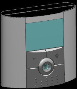
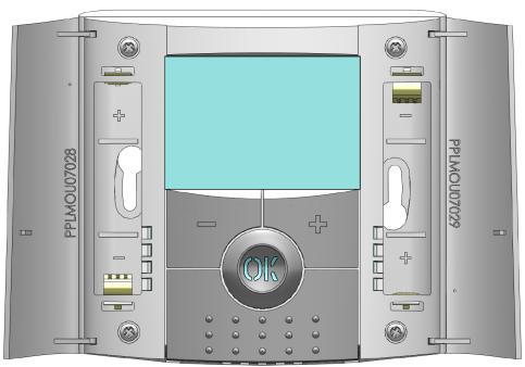
9 1.1 Keyboard Minus Key (-) Plus Key (+) Validation Key (OK) Status LED Left Navigation key ( ) Right navigation key ( ) Escape key ( ) Edition key ( ) 9
: Heating demand Green flash:")

10 1.2 Display & LED Red Fix (when backlight is lit up): Heating demand Green flash: your validation is required Red flash: Error on sensor or batteries
11 1. Operating mode menu (active mode is framed). 2. parameter number if 3 is displayed. 3. Installation Parameter menu. 4. Type of sensor used and temperature displayed. Regulation => Internal or external ambient sensor. Regulation => Floor sensor. Regulation => Internal sensor with Floor limitation. View of the outside temperature 5. Heating demand indication. 6. Low batteries indicator. 7. C or F unit indicator 8. Setting or measured temperature if 2 is displayed. Parameter value if 3 is displayed. 9. Key lock indicator 11
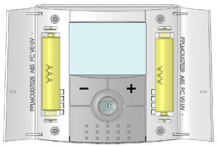
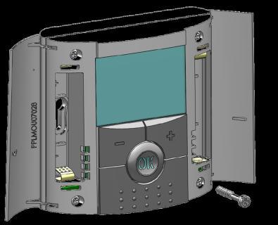
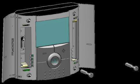
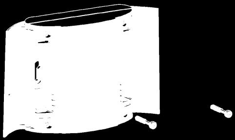
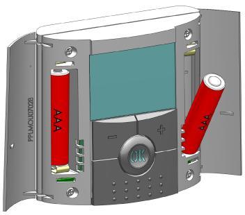
12 2 First Installation This section will guide you to set up your thermostat for the first time. 2.1 Batteries installation - Open the two sides covers and Insert the 2 AAA Alkaline supplied batteries (or remove the small protection sticker if the batteries are already installed in the compartment) - Close the two side s covers. - Now your thermostat will propose you to adjust the current time and date. 2.2 Starting The thermostat is now ready to works. The default working mode will be Comfort 12

13 3 Working mode definition How to change the working mode? - Open the small center cover to have access to the navigation keys ( ) or ( ). - You can now press theses keys to display the working mode line. Move the frame cursor on the desired working mode and press (OK) to enter in the operating mode you have chosen. 13
14 3.1 Manual mode Comfort Manual working mode, the comfort setting temperature will be followed all the time. By pressing (-) or (+) keys, the comfort setting temperature starts to blink and can be adjusted. 3.2 Manual mode, Reduced Manual working mode, the reduced setting temperature will be followed all the time. By pressing (-) or (+) keys, the reduced setting temperature starts to blink and can be adjusted. 3.3 OFF mode Use this mode if you need to switch off your installation. Be Careful: In this mode your installation can freeze. 14
15 - At any time, when display is off, press on the (Ok) key to display a few seconds the current temperature and time. - To restart your installation, use the navigation keys ( ) or ( ). 3.4 Anti freeze mode Use this mode if you want to protect your system against freezing when going on holiday... - The anti-freeze setting temperature is fixed and can be adjusted in the parameter menu number 06 HG, see chapter 6. (Default value 10 C) 15
16 3.5 Timer mode The Timer mode allows you to adjust, the temperature and the duration for a special time. This function can be used when you stay at home for several days, or if you want to override the program for some time (reception...) - You can first adjust, the duration in hours H if below 24H, then in day d with (-) or (+), press (OK) to validate. (Adjustable 1 Hour to 99 days) - In a second time, you can adjust the desired setting temperature with (-) or (+), press (OK) to start the function. (Default value 22 C) The logo will be blinks and the number of hours /days left is displayed until the end of the period. 16
17 If you want to stop the Timer function before the end, set the duration period to no with (-) key. 4 Special function 4.1 Keyboards lock Function Use this function to prevent all change of your settings (In a child room, public area ) - To activate the Key lock function, first press maintain the escape key ( ) and then press simultaneously on the edition key ( ). - The logo will be displayed on the screen. - Repeat the same procedure to unlock the key board. 17
18 4.2 Information With this function You can quickly view all currents temperatures of the probe sensors connected to your thermostat (Floor, external or outside sensor) by several presses on the escape key ( ).This Scroll function is only available in the main screen. You can view: - The current setting temperature followed by the thermostat. - The ambient temperature - If external sensor is connected:the outside temperature Other opportunities will be available by connecting an external sensor on your thermostat. Contact your supplier or installer for more information about these options. 18
 or ( ), once the parameter chosen,")
19 5 Parameter s menu Your thermostat has a parameter s menu, in order to enter in this menu, press and maintain the edition key ( ) during 5sec. Then parameter menu will appear and first parameter screen will be displayed: Now you can select a parameter which must be adjusted with the navigation keys ( ) or ( ), once the parameter chosen, toggle the value with the (OK) key, modify it with (-) or (+) and confirm your adjustment with (OK). To leave the parameter menu, choose the parameter «End» and press (OK). 19
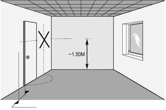
20 N Default value & other possibilities 01 deg: Unit of the temperatures displayed C Celsius F Fahrenheit 04 AirC: Calibration of the internal probe The calibration must be done after 1 day working with the same setting temperature in accordance with the following description: Put a thermometer in the room at 1.5M distance from the floor (like the thermostat) and check the real temperature in the room after 1 hour. When you enter on the calibration parameter no is displayed on the right to indicate no calibration has made. To enter the value shown on the thermometer, use the (-) or (+) keys to enter the real value. Then, press (Ok) to confirm. The message Yes should be displayed; the value will be stored in the internal memory. If you need to erase a calibration press on the escape key ( ). The old value will be erased and the message no will be displayed. * Pay attention: 20
21 Only the heating element driven by the thermostat must be used during the complete step of the calibration. 05 OutC, AMbC, FlrC: Calibration of the external wired probe Same calibration method as described in parameter 04 AirC above. 06 HG: Anti-freeze temperature used in Holiday mode Default value 10 C. Use the (-) or (+) keys to change the anti-freeze setting temperature. Then press (Ok) to confirm. 08 Clr ALL: Reset to Factory setting Press and maintain (Ok) key during 10s to reset Set points temperatures and user parameters in this menu to factory default settings. User programs will also be resetted. * Pay attention: Ensure you that you have all necessary elements to resetup your installation before to use this function. 09 Software version VErS 10 End: Exit the parameter s menu Press (OK) key to exit installation parameter menu and return to normal operation. 21
22 6 Technical characteristics Measured temperature precision Environmental: Operating temperature: Shipping and storage temperature: Setting temperature range Comfort and Eco Anti freeze Timer Regulation characteristics minimum time to start and stop Electrical Protection Power Supply Operating life 0.1 C 0 C - 40 C -10 C to +50 C 5 C to 35 C by 0,5 C step C 5 C to 35 C Proportional Band (PWM 2 C for 10min cycle) or Hysteresis of 0.5 C 2 minutes ON and OFF (configurable) Class II - IP30 2 AAA LR03 1.5V Alkaline ~2 years 22
23 Type of contact 2 wires (free contact) Screw connectors <1.5mm². Maximum Load Up to 3A - 250Vac 50Hz Optional External sensor 10k ohms at 25 C Displayed in the user Software version menu. Norms and homologation: EN : 2003 EN : 2002 EN : 2004 EN : 2001 Your thermostat has been designed in conformity with the following standards or other normative documents: Low voltage 2006/95/CE EMC 2004/108/CE 23
24 7 Troubleshooting & Solution Batteries Problem My BT D doesn t start - Check if the protection sticker on the batteries is removed. - Check the batteries orientation. - Check the capacity of the batteries My BT D Led, blinks in Red Problem on sensors Batteries level is too less The logo blinks (ambient sensor) - Contact your installer or seller. The logo blinks (Floor sensor) - Check the connection of the sensor. - Disconnect the sensor, and check it with an ohmmeter (the value must be around 10kohms) The logo blinks (Batteries) - Replace the batteries. 24
25 My BT D seems work correctly but the heating doesn t work correctly - Check the connections. - Check the power supply of the Output heating element. - Contact your installer. My BT D seems work correctly but the temperature in the room was never in accordance with the program. - Try to calibrate your thermostat (see user menu parameter 04) Temperature - Contact your installer, to check & adjust the regulation parameters with your heating system. 25


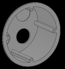

26 80 mm D Installation GB Installation F Installation E Instalación I Installazione P instalação NL installatie FIN Asennus SE Installation N Installasjon 1 2 t C ~1,20M Volt free connection Min 20cm Max 1mm² 2 wires + NTC 10k (25 C) 3 83mm 27mm 60mm PPLIMP09460Aa
27 PPLIMP12568Aa 144 rev : 9/01/2012
,")
 or ( ).")
 key.")

28 Advanced installer s parameters menu GB Watts BT- Dx range External sensor NTC type 10k Ω at 25 C (ß = 3950) How to accede it on the D version Press 10 sec on the key In order to enter in the menu, select and valid the OFF mode ( ), then press on the escape key during 10 seconds, the following display with the first parameter must be appears: - Once you entered in the menu, go to the parameter which you want change by using the keys ( ) or ( ). - Use the keys (+) or (-) to edit and modify and confirm by pushing the (OK) key. - To leave the parameter menu, go to the parameter End and press the (OK) key. Note: You could reload one parameter to the default value if you press the escape key when the parameter value blinks. Parameters 20 Mod Working mode Installer s Advanced Menu N names Description of the parameter Factory value Other possibility cld For cooling Application Hot For heating application Rev The working mode can be done by the end user
29 The two followings parameters are only available on the wired version BT-D NC 21 Out Type of output Normally Closed (Output closed when demand) Anti-lock-braking function for pump. Yes 22 PmP When the pump hasn t worked on a particular day, start Function it up for one minute each day activated directly on the main menu. For reversible application NO Normally Open (Output opened when demand) No Function deactivated FLR Floor sensor regulation 23 REG Selection of the sensor used for the regulation. AIR Internal ambient sensor FL.L Air regulation with floor limitation possibilities (see parameters 26&27) C View of the measured values of the ambient sensor.._ amb External ambient sensor C View of the measured values of the floor (external) sensor. 26 FL.L Lower limit of the floor temperature. no The lower limitation is not used._ From 5 C to FL.H 27 FL.H Upper limit of the floor temperature. 28 Typ Selection of regulation type 29 tcy 29 HYS Only available if the parameter 28 is set on reg value. Selection of the proportional band duration in minutes (cycle duration) Only available if the parameter 28 is set on HySt value. Selection of the hysteresis value in C no The upper limitation is not used Reg Proportional band (PWM) 10 Ideal value for all Electrical floors heating application. 30 t.on Minimal starting time in minutes t.of Minimal resting time between 2 heating cycles in minutes 32 Bp 33 Cp Value of the proportional band in C Note: If the value of proportional band is too big the system reactivity will be slower and could affect the steps of the program. Compensating value of the regulation This value will need to be modified only if the thermostat is perturbed by the heating element. Generally never the case with electrical floor heating. 34 rst Reset All parameters will be reloaded with the factory value. From FL.L to 37 C hys Hysteresis (On/Off) You could increase this value if the thermostat is used for other heating application (Oil Boiler...) Ideal value for all Electrical floors heating application Adjustable 0 to T cy/2 Adjustable 0 to T cy/2 Adjustable 1 to 6.0 A well insulated house «1.5 C» A not insulated house «4 C» Adjustable 0 to 14.0 Increase this value if the thermostat is too close to the heating source. Press on the (OK) key during few seconds. 35 End To exit the installer s menu Press on the (OK) to exit.
TIMER INTERFACE USER MANUAL
 TIMER INTERFACE USER MANUAL Premium Efficiency Two-Speed Motor with Integrated Timer Formerly A. O. Smith Electrical Products Company A Regal Beloit Company COPYRIGHT Copyright 2011, Regal Beloit EPC,
ELIOS 25 DIGITAL CONTROL UNIT WITH LCD DISPLAY FOR THERMAL SOLAR SYSTEMS TDS 006 M00 0SE A
 ELIOS 25 DIGITAL CONTROL UNIT WITH LCD DISPLAY FOR THERMAL SOLAR SYSTEMS TDS 006 M00 0SE 012945A0 040906 1 MAIN FEATURES Power supply 230V~ ±10% 50Hz Backlit alphanumeric LCD display Management of 5 output
ST48-WHUV.102. Wiring diagram. Product description. PID controller. Order number
 ST48-WHUV.12 PID controller Order number 935.15 Wiring diagram Product description This micro-processed controller serves for temperature control at high measuring accuracy. Beside resistance sensors and
HERZ Electronic room thermostat analog and digital
 Dimension in mm 3 F799 11-3 F799 14 HERZ Electronic room thermostat analog and digital Data sheet for F799, Issue 0317 3 F799 15 3 F799 18 Mounting plate Page 1 Technical data 3 F799 11-14 3 F799 15-18
OPERATING MANUAL Digital Diesel Control Remote control panel for WhisperPower generator sets
 Art. nr. 40200261 OPERATING MANUAL Digital Diesel Control Remote control panel for WhisperPower generator sets WHISPERPOWER BV Kelvinlaan 82 9207 JB Drachten Netherlands Tel.: +31-512-571550 Fax.: +31-512-571599
DT304. Digital Temperature Logger INSTRUCTION MANUAL
 Test Equipment Depot - 800.517.8431-99 Washington Street Melrose, MA 02176 - TestEquipmentDepot.com DT304 INSTRUCTION MANUAL Digital Temperature Logger TABLE OF CONTENTS Introduction..........................................1
INSTALLER MANUAL USER MANUAL. Contents
 Installation & user manual two way Contents INSTALLER MANUAL Important information General 1. Technical data 2. Description Installation: 1. Positioning the unit 2. Connection. 3. Parts description. 4.
Rally computer 3 Rally computer 3.GPS *
 Rally computer 3 Rally computer 3.GPS * User manual. Installation and configuration instructions. (with links to video instructions online at : www.rallycomputer.com ) * Content marked applies only to
! WARNING To avoid risk of electrical shock, personal injury, or death, disconnect power to range before servicing, unless testing requires power.
 Electric Freestanding Range Technical Information MER5875RA* Due to possibility of personal injury or property damage, always contact an authorized technician for servicing or repair of this unit. Refer
! WARNING To avoid risk of electrical shock, personal injury or death; disconnect power to oven before servicing, unless testing requires power.
 Technical Information Electric Slide-In Range JES9750AAB/S/W JES9800AAB/Q/S/W JES9860AAB/S/W Due to possibility of personal injury or property damage, always contact an authorized technician for servicing
RDG160TU Commercial Thermostat
 Document No. 129-588 RDG160TU Commercial Thermostat Selecting Location Install the thermostat about 4 feet (120 cm) above the floor on an inside wall. Ensure that there is free airflow around the thermostat.
MC200CAB/4 Integral Version
 Issue 2.2 Mar 2017 MC200CAB/4 Integral Version Industrial & Commercial Heating Systems. www.powrmatic.co.uk Setting Instructions WARNING: THIS APPLIANCE MUST BE EARTHED IMPORTANT: Reset from Lockout is
! WARNING To avoid risk of electrical shock, personal injury or death; disconnect power to oven before servicing, unless testing requires power.
 Technical Information Double Oven Dual Fuel Range JDR8895AAB/S/W Due to possibility of personal injury or property damage, always contact an authorized technician for servicing or repair of this unit.
ST Wiring diagram. Product description. Temperature controller. Order number
 ST7-31.3 Temperature controller Order number 9154.12 Wiring diagram Product description The switching exits of the thermostatic controller can be programmed as -two-point controller with alarm -three-point
! WARNING To avoid risk of electrical shock, personal injury or death; disconnect power to range before servicing, unless testing requires power.
 Double Oven Electric Range Technical Information MER6765BA* Due to possibility of personal injury or property damage, always contact an authorized technician for servicing or repair of this unit. Refer
Instruction Manual. Single-Input Thermistor Thermometer (Model )
") Instruction Manual Single-Input Thermistor Thermometer (Model 91428-05) 68X001349 Rev0 0717 1065DGMAN_91428-05 TABLE OF CONTENTS 1. QUICK-START GUIDE... 1 2. INTRODUCTION... 2 3. SAFETY PRECAUTIONS...
Instruction Manual Single-Input Thermistor Thermometer (Model 91428-05) 68X001349 Rev0 0717 1065DGMAN_91428-05 TABLE OF CONTENTS 1. QUICK-START GUIDE... 1 2. INTRODUCTION... 2 3. SAFETY PRECAUTIONS...
! WARNING To avoid risk of electrical shock, personal injury, or death, disconnect power to range before servicing, unless testing requires power.
 Electric Freestanding Range Technical Information AER5712BA* MER5751BA* MER5752BA* MERH752BA* MERM752BA* Due to possibility of personal injury or property damage, always contact an authorized technician
Grain Moisture Meter. Operators manual
 Grain Moisture Meter Operators manual Operation EN COMPONENTS 1 TESTER 2 BATTERY DOOR 3 USB DOOR 4 USB CABLE 5 CARRYING CASE 1 4 2 5 3 A A - Test Cell B - Display C - Keyboard D - Cap E - Pressure-indicator
! WARNING To avoid risk of electrical shock, personal injury or death; disconnect power to oven before servicing, unless testing requires power.
 Technical Information Double Oven Electric Range MER6555AAB/Q/W MER6751AAB/Q/S/W MER6755AAB/Q/S/W MER6775AAB/F/N/Q/S/W Due to possibility of personal injury or property damage, always contact an authorized
INSTALLATION/OPERATING INSTRUCTIONS VSP. A Variable Speed Pump Control
 INSTALLATION/OPERATING INSTRUCTIONS VSP A Variable Speed Pump Control The VSP is a hydronic heating control. The temperature of the heating water is controlled by regulating the speed of a pump which injects
Temp-14 Single Input Thermistor Thermometer
 Instruction Manual Temp-14 Single Input Thermistor Thermometer Part of Thermo Fisher Scientific 68X481902 Rev 0 10/08 TABLE OF CONTENTS 1. Quick Start Guide... 1 2. Introduction... 2 3. Safety Precautions...
B-RAD Select USER MANUAL TABLE OF CONTENTS
 TABLE OF CONTENTS TABLE OF CONTENTS... 1 MANUAL REVISION HISTORY... 2 IMPORTANT SAFETY NOTICE... 3 1.0 General Information... 5 1.1 System Components... 5 1.2 Specifications... 5 1.2.1 Torque Ranges...
A419ABG-3C Electronic Temperature Control
 Installation Instructions Issue Date June 16, 2003 A419ABG-3C Electronic Temperature Control Application IMPORTANT: Use this A419ABG-3C Electronic Temperature Control only as an operating control. Where
! WARNING To avoid risk of electrical shock, personal injury or death; disconnect power to oven before servicing, unless testing requires it.
 Electric Wall Oven Technical Information AEW3630DD*, AEW4630DD*, JJW8230DD* MEW5627DD*, MEW5630DD*, MEW6627DD*, MEW6630DD*, Refer to Service Manual 6022506 for detailed installation, operating, testing,
INSTALLATION/OPERATING INSTRUCTIONS TSC
 INSTALLATION/OPERATING INSTRUCTIONS TSC Two-Stage Set Point Control with External Activation Two-Stage Heating (Rotation Included) Two-Stage Cooling (Rotation Included) Change-Over Control (Heat/Cool)
CAUTION All safety information must be followed as provided in Service Manual
 Double Oven Gas Range Technical Information MGR6875AD* Due to possibility of personal injury or property damage, always contact an authorized technician for servicing or repair of this unit. Refer to Service
ECLIPSE Laundry Dispenser Controller
 ECLIPSE Laundry Dispenser Controller Reference Manual Programming and Operation Online and downloadable Product Manuals and Quick Start Guides are available at www.hydrosystemsco.com Please check online
Rutland Remote Display -Model Installation and Operation
 Rutland Remote Display -Model 1200 Installation and Operation Introduction The Rutland Remote 1200 Model is designed for use with the Rutland 1200 Wind Turbine. It enables convenient viewing of the wind
! WARNING To avoid risk of electrical shock, personal injury or death; disconnect power to oven before servicing, unless testing requires power.
 Technical Information Gas Slide-In Range JGS8750ADB/S/W JGS8850ADB/Q/S/W Due to possibility of personal injury or property damage, always contact an authorized technician for servicing or repair of this
CM707 (UK Version) PROGRAMMABLE THERMOSTAT FEATURES PRODUCT SPECIFICATION SHEET
 PROGRAMMABLE THERMOSTAT FEATURES PRODUCT SPECIFICATION SHEET") CM707 (UK Version) PROGRAMMABLE THERMOSTAT PRODUCT SPECIFICATION SHEET The CM707 thermostat is designed to provide automatic time and temperature control of heating systems in villas and apartments. It
CM707 (UK Version) PROGRAMMABLE THERMOSTAT PRODUCT SPECIFICATION SHEET The CM707 thermostat is designed to provide automatic time and temperature control of heating systems in villas and apartments. It
KIT-STCS60D KIT-STCS100D Solar Suitcase 60W and 100W Owner s Manual
 KIT-STCS60D KIT-STCS100D Solar Suitcase 60W and 100W Owner s Manual RNG Group Inc. (Renogy) 14288 Central Ave., Suite A Chino, CA 91710 1-800-330-8678 Product Description The Renogy Solar Suitcases combine
A419 Series Electronic Temperature Controls with Display and NEMA 1 or NEMA 4X Watertight Enclosures
 A419 Issue Date February 10, 2003 A419 Series Electronic Temperature Controls with Display and NEMA 1 or NEMA 4X Watertight Enclosures The A419 series controls are single-stage, electronic temperature
Factory Packaged Controls. OE (AAON Part No. V12090) MODGAS-X Controller Field Technical Guide
 MODGAS-X Controller Field Technical Guide") Factory Packaged Controls OE377-26-00058 (AAON Part No. V12090) MODGAS-X Controller Table of Contents GENERAL INFORMATION... 3 Overview...3 Features...3 INSTALLATION & WIRING... 4 Supply Air Temperature
Factory Packaged Controls OE377-26-00058 (AAON Part No. V12090) MODGAS-X Controller Table of Contents GENERAL INFORMATION... 3 Overview...3 Features...3 INSTALLATION & WIRING... 4 Supply Air Temperature
User Manual. Solar Charge Controller 3KW
 User Manual Solar Charge Controller 3KW 1 CONTENTS 1 ABOUT THIS MANUAL... 3 1.1 Purpose... 3 1.2 Scope... 3 1.3 SAFETY INSTRUCTIONS... 3 2 INTRODUCTION... 4 2.1 Features... 4 2.2 Product Overview... 5
TABLE OF CONTENTS 11.0 WARRANTY
 11.0 WARRANTY ELECTROMATIC Equipment Co., Inc. (ELECTROMATIC) warrants to the original purchaser that this product is of merchantable quality and confirms in kind and quality with the descriptions and
! WARNING To avoid risk of electrical shock, personal injury or death; disconnect power to range before servicing, unless testing requires power.
 Double Oven Electric Range Technical Information MER6875BA* Due to possibility of personal injury or property damage, always contact an authorized technician for servicing or repair of this unit. Refer
MT-1 Tracer Meter. RENOGY MT-1 Tracer Meter for Duo Battery Charge Controller E. Philadelphia St., Ontario CA
 MT-1 Tracer Meter RENOGY MT-1 Tracer Meter for Duo Battery Charge Controller 2775 E. Philadelphia St., Ontario CA 91761 1-800-330-8678 1 Version: 1.0 Table of Contents Important Safety Instructions...3
Coating Thickness Gauges
 OI502 CHECK LINE BY ELECTROMATIC Coating Thickness Gauges DCF-3000EZ-E AND DCFN-3000EZ-E Operating Instructions TABLE OF CONTENTS 1.0 Introduction.......................................... 02 2.0 Overview.............................................
User Manual Solar Charge Controller 3KW
 User Manual Solar Charge Controller 3KW Version: 1.3 CONTENTS 1 ABOUT THIS MANUAL... 1 1.1 Purpose... 1 1.2 Scope... 1 1.3 SAFETY INSTRUCTIONS... 1 2 INTRODUCTION... 2 2.1 Features... 2 2.2 Product Overview...
CM707 PROGRAMMABLE THERMOSTAT FEATURES PRODUCT SPECIFICATION SHEET
 CM707 PROGRAMMABLE THERMOSTAT PRODUCT SPECIFICATION SHEET The CM707 thermostat is designed to provide automatic time and temperature control of heating systems in villas and apartments. It can be used
Positive displacement batch controller
 8075 Batch controller Positive displacement batch controller Type 8075 can be combined with... Compact version for DN15 to DN100 Dosing On site calibration by Teach-In Check of input/output signals Total
EXPERT 2V4SA. Temperature Controller. User s manual CLEAN MODE COMPENSATION HUMIDITY OUTSIDE TEMPERATURE
 CLEAN MODE Temperature Controller User s manual CURRENT CONDITIONS ROOM TEMPERATURE PROBE TEMPERATURE OUTSIDE TEMPERATURE RELATIVE HUMIDITY STATIC PRESSURE TIME / DATE SETTINGS SET POINT / CURVE MINIMUM
TC62D Installation Instructions
 TC62D Installation Instructions January 2007 This TC62D has a return water low temperature limit option. Using the low limit precludes using a room sensor because both sensors plug into the same port.
Single-Input Thermocouple. Thermometers Type J, K, T
 Instruction Manual Single-Input Thermocouple Single-Input Thermocouple Thermometers Type J, K, T Thermometers Type J, K, T 68X001351 Rev0 0717 1065DGMAN_91428-00,-01,-02 TABLE OF CONTENTS 1. INTRODUCTION...
January 10, 2017 # Rev. B. Model 464 Mk3 Electronic Pump Control Unit User Guide
 January 10, 2017 #109652 Rev. B Model 464 Mk3 Electronic Pump Control Unit User Guide Model 464 Electronic Control Unit User Guide - Contents 1.0 Introduction 1 1.1 Operating Principles 1 1.2 Model 464
DCC-2500 Digital Climate Control for Vintage Air GEN-IV systems
 INSTALLATION AND OPERATOR S MANUAL FOR DCC-2500 Digital Climate Control for Vintage Air GEN-IV systems PARTS INCLUDED WITH THIS SYSTEM Vent sensor housings: 2 1 / 2 housings (x2) 2 housings (x2) Installation/operator
9142-B-P-156/AF. User s Guide. Field Metrology Well. Distribution is limited to DoD and U.S. DoD contractors only.
 9142-B-P-156/AF Field Metrology Well User s Guide Distribution is limited to DoD and U.S. DoD contractors only. May 2013 2013 Fluke Corporation. All rights reserved. Specifications are subject to change
G72x Series Direct Spark Ignition Controls
 Installation Sheets Manual 121 Gas Combustion Combination Controls and Systems Section G Technical Bulletin G72x Issue Date 1299 G72x Series Direct Spark Ignition Controls Figure 1: G72x Direct Spark Ignition
MoistureMatch A next generation grain tester
 MoistureMatch A next generation grain tester A next generation moisture tester incorporating new and unique technology. Finally, a portable tester that will more accurately match and track with the commercial
VMB1TS Temperature sensor module for the Velbus system
 VMB1TS Temperature sensor module for the Velbus system VMB1TS manual edition 2 1 CONTENTS DESCRIPTION... CHARACTERISTICS... VELBUS CHARACTERISTICS... 5 OVERVIEW SENSOR MODULE... 7 EMBEDDING THE TEMPERATURE
SWA-2441/2451 PID TEMPERATURE CONTROLLER INSTRUCTION MANUAL
 Instruction Manual SWA-2441/2451 PID TEMPERATURE CONTROLLER INSTRUCTION MANUAL Version 1.14 (August, 215) 1. Caution 3. Terminal Assignment Model SWA-2441 Model SWA-2451 This controller is intended to
A419 Series Electronic Temperature Controls with NEMA 1 or NEMA 4X Watertight Enclosures
 Installation Instructions Issue Date April 8, 2008 A419 Series Electronic Temperature Controls with NEMA 1 or NEMA 4X Watertight Enclosures Application IMPORTANT: The A419 Series Electronic Temperature
Installation Guide. ECL Comfort 210 / 310, application A231 / A Table of Contents
 1.0 Table of Contents 1.0 Table of Contents... 1 1.1 Important safety and product information..................... 2 2.0 Installation... 4 2.1 Before you start.....................................................
GENERAL INFORMATION. H-1649, H-1650, H-1651 H-1653, H-1654 Easy-Count. uline.com. that may hurt accuracy:
 π H-1649, H-1650, H-1651 H-1653, H-1654 Easy-Count counting scale 1-800-295-5510 uline.com 1-800-295-5510 GENERAL INFORMATION Avoid placing the scale in locations that may hurt accuracy: 1. Temperature
SPEEDRIVE INSTRUCTIONS MANUAL
 EN SPEEDRIVE INSTRUCTIONS MANUAL Safety warning. The following symbols shown beside a paragraph represent danger warnings associated to the failure to comply with the corresponding instructions. DANGER!
Cafitesse. Quantum 110. Operator manual
 Cafitesse Quantum 110 Operator manual 595228100 2016-02 Copyright 2016 JACOBS DOUWE EGBERTS, Netherlands The English version is the original version of the operator manual. Other languages are translations
MAGPOWR Spyder-Plus-S1 Tension Control
 MAGPOWR TENSION CONTROL MAGPOWR Spyder-Plus-S1 Tension Control Instruction Manual Figure 1 EN MI 850A351 1 A COPYRIGHT All of the information herein is the exclusive proprietary property of Maxcess International,
HP21 SERVICE SUPPLEMENT UNIT INFORMATION. TSC6 Two-Speed Control
 SERVICE UNIT INFORMATION SUPPLEMENT HP21 Corp. 9426 L10 Litho U.S.A. All HP21-4 and -5 units (single and three phase) are equipped with a TSC6 two-speed control. The TSC6 (A14) two-speed control contains
Technician Manual. Electronic Table -Top Autoclaves Models EZ9Plus & EZ11Plus
 Technician Manual Electronic Table -Top Autoclaves Models EZ9Plus & EZ11Plus Cat. No. MAN205-0443002EN Rev. E Manufactured by: Tuttnauer Co. Ltd., Har Tuv Industrial zone B P.O.Box 170, Beit Shemesh 99000,
INSTALLATION/OPERATING INSTRUCTIONS MCP
 INSTALLATION/OPERATING INSTRUCTIONS MCP Modulating Digital Set Point Control with Boiler Output and External Activation Temperature Range -30 to 250 F (-35 to 120 C) Pressure Ranges 0-30, 0-100, 0-200PSI
Service Manual BLACK DIAMOND SERVICE MANUAL. V.160 November
 BLACK DIAMOND SERVICE MANUAL V.160 November 2011 www.montrealchargeur.com www.battelec.ca www.doctorfleet.com Page 1/30 1. SAFETY PRECAUTIONS 1 Before to start using the Black Diamond Charger, read these
PowerView PV380-R2 Mechanical Configuration
 PowerView PV380-R2 Mechanical Configuration Operations Manual *Products covered in this document comply with European Council electromagnetic compatibility directive 2004/108/EC and electrical safety directive
Solar Controller SUNGO S
 OPERATING INSTRUCTIONS, Issue SW1201/ 2.01/ HW2.4 Solar Controller SUNGO S Wagner& Co Figure 1 Solar Controller SUNGO S. The benefits at a glance Large display to indicate temperature, balance values and
Instruction Manual. Duo-battery Solar Panel Controller EPIP20-DB series For Both 10 and 20 amp. Controllers (for use with solar panels only) + -
 + -") Instruction Manual Duo-battery Solar Panel Controller EPIP20-DB series For Both 10 and 20 amp. Controllers (for use with solar panels only) + - Optional - Switch to disconnect solar panel when engine alternator
Instruction Manual Duo-battery Solar Panel Controller EPIP20-DB series For Both 10 and 20 amp. Controllers (for use with solar panels only) + - Optional - Switch to disconnect solar panel when engine alternator
51 & 52 Series II. Users Manual. Thermometer. Test Equipment Depot Washington Street Melrose, MA TestEquipmentDepot.
 51 & 52 Series II Thermometer Test Equipment Depot - 800.517.8431-99 Washington Street Melrose, MA 02176 - TestEquipmentDepot.com Users Manual English September 1999 Rev.2, 11/10 1999-2010 Fluke Corporation,
MiG2 TIME SWITCHES. 1, 2 & 4 Channel, 365 Day, Energy Saving Time Switches
 MiG2 TIME SWITCHES 1, 2 & 4 Channel, 365 Day, Energy Saving Time Switches The MiG2 series of timers are programmable 365-day time-switches, incorporating: Multiple switching times per day Single and block
The RCS-6V kit. Page of Contents. 1. This Book 1.1. Warning & safety What can I do with the RCS-kit? Tips 3
 The RCS-6V kit Page of Contents Page 1. This Book 1.1. Warning & safety 3 1.2. What can I do with the RCS-kit? 3 1.3. Tips 3 2. The principle of the system 2.1. How the load measurement system works 5
Thermistor Thermometer MODEL NO
 Digi -Sense Thermistor Thermometer MODEL NO. 60010-70 Digi -Sense CERTIFICATE OF CONFORMANCE This thermometer was calibrated using equipment traceable to the National Institute of Standards and Technology
BRAKE TESTER DECELEROMETER
 OC3010_GBM_21009 BRAKE TESTER DECELEROMETER OWNER S MANUAL Version 8.++ ORBIT CONTROLS AG Zürcherstrasse 137 CH-8952 Schlieren/ZH Tel: + 41 44 730 2753 Fax: + 41 44 730 2783 info@orbitcontrols.ch www.orbitcontrols.ch
SB 2000 PUSH TO SEARCH NEXT STAG E. Aerotech, Inc. FORM: QM 1320
 Inlet Controller SB 2000 USER'S MANUAL AUTO OPEN MANUAL PUSH TO SEARCH NEXT STAG E CLOSE Aerotech, Inc. FORM: QM 1320 4215 Legion Dr. Mason, MI 48854-1036 USA Rev. 3, Sept. 1997 Ph. (517) 676-7070 Fax
Model 322 Automated Thermocouple Calibrator Operating Instructions. Product Description. Practical Instrument Electronics
 Model 322 Automated Thermocouple Calibrator Operating Instructions Product Description Easy to use With the PIECAL 322 you can check & calibrate all your thermocouple instruments and measure thermocouple
Products for specific requirements
 SIDOOR Manual 02/2012 Products for specific requirements Answers for industry. Introduction 1 Safety notes 2 Products for specific requirements SIDOOR Manual Definitions 3 Overview of controls 4 Functions
CA 180 Owner's Manual
 Remote Vehicle Control System CA 180 Owner's Manual Deluxe Vehicle Security System with Two Way Confirming Dot Matrix Remote Control IMPORTANT NOTE: The operation of the Security and Convenience System
SMT-AZC INSTALLATION / OPERATION MANUAL
 SMT-AZC INSTALLATION / OPERATION MANUAL 22o OFF VERSION 2.0 www.smarttemp.com INTRODUCTION The SMT-AZC thermostat is designed to work with the Smart Temp 24Volt Zone Dampers TERMINAL DESIGNATIONS The SMT-AZC
Mitsubishi. VFD Manuals
 Mitsubishi VFD Manuals Mitsubishi D700 VFD Installation Mitsubishi FR-D700 VFD User Manual Mitsubishi D700 Parallel Braking Resistors VFD Wiring Diagram - Apollo Mitsubishi VFD to Interpreter Mitsubishi
ENGLISH SAFETY INSTRUCTIONS. Recommendations for safe operation. Operator safety. General warnings
 Safety and use instructions LifeSpeed iq TM - 3-phase chargers ENGLISH SAFETY INSTRUCTIONS GOALS OF THIS MANUAL This manual is aimed at any authorized personnel wanting to use a 3-phase LifeSpeed iq TM
SWA-24X2C PID Temperature Controller with Timer (SWA-2442C/2452C)
") Instruction Manual SWA-24X2C PID Temperature Controller with Timer (SWA-2442C/2452C) Version 1.4 (v, 2016) 1. Caution This controller is intended to control equipment under normal operating conditions.
Instruction Manual SWA-24X2C PID Temperature Controller with Timer (SWA-2442C/2452C) Version 1.4 (v, 2016) 1. Caution This controller is intended to control equipment under normal operating conditions.
PAGE Both power cords must be connected & powered to operate the E-TES SD 120 volt unit.
 PAGE 1 This document outlines questions to ask and components to check during E-TES SD 120 volt troubleshooting. More detailed troubleshooting procedures are available in the E-TES SD 120 volt Troubleshooting
VC-4820 Programmable DC-DC Converter with Battery Charger function USER'S MANUAL
 1. INTRODUCTION VC-4820 Programmable DC-DC Converter with Battery Charger function USER'S MANUAL This MCU controlled Step Down DC-DC Converter has a digitally adjustable output in 0.2V increments. This
Features: Enhanced throttle response, excellent acceleration, strong brakes and throttle linearity. Using LED program card to make adjustments.
 Thank you for purchasing the ZTW Brushless Electronic Speed Controller (ESC). The ZTW 1:10 Scale BEAST Series ESC is specifically designed for operating 4 Pole Sensorless brushless motors. This is a high
Temperature Controller OVATION 214 User's Guide
 Temperature Controller User's Guide Read this guide carefully before using the controller. 890-00045 rev.00 TABLE OF CONTENTS Page TABLE OF CONTENTS... 2 PRECAUTIONS... 3 FEATURES... 4 LOCATION OF THE
User manual. Standard Modular Chiller HP 1/8 compressors with CAREL driver Application program for pco 1, pco 2, pco 3, pco C and pco XS.
 Standard Modular Chiller HP 1/8 compressors with CAREL driver Application program for pco 1, pco 2, pco 3, pco C and pco XS. User manual Manual version: 2.4 dated 27/02/08 Program code: FLSTDmMCDE LEGGI
Phoenix Inverter
 Manual EN Handleiding NL Manuel FR Anleitung DE Manual ES Appendix Phoenix Inverter 12 250 12 375 12 500 12 800 24 250 24 375 24 500 24 800 48 250 48 375 48 500 48 800 1. Safety instructions WARNING: ELECTRIC
OPERATING INSTRUCTIONS FOR SLIDING DOOR RETROFIT CONTROLLER DC-02
 OPERATING INSTRUCTIONS FOR SLIDING DOOR RETROFIT CONTROLLER DC-02 1. INTRODUCTION 2. SAFETY INSTRUCTIONS 3. SPECIFICATION 4. OPERATING INSTRUCTIONS AND CONTROL FUNCTIONS 5. SET UP PROCEDURE 6. CONNECTIONS
BATTERY CHARGER RS-1000 Instruction Manual
 BATTERY CHARGER RS-1000 Instruction Manual BEFORE USING OUR BATTERY CHARGER RS1000, READ IN DETAILS ALL INSTRUCTIONS CONTAINED IN THIS MANUAL. KEEP THIS MANUAL IN A SAFE PLACE AS YOU MAY NEED TO USE IT
c-go 24V/6A 24V/8A 24V/12A
 c-go 24V/6A 24V/8A 24V/12A Battery charger GB Instruction manual 1 Index 1. Product description... 2 2. Safety advices... 3 3. Quick start guide... 4 4. Operation... 4 5. Problem solving... 6 6. Specifications...
Features: Enhanced throttle response, excellent acceleration, linearity and driveability
 120A/150A ESC X-Car 120A/150A Series Sensored/Sensorless Brushless ESC for 1:8 scale Car or Truck Thank you for purchasing the X-Car Brushless Electronic Speed Controller (ESC). The X-Car 1:8 Scale 120A/150A
OPERATING MANUAL SCOOTER, Control panel with LCDdisplay
 GB OPERATING MANUAL SCOOTER, Control panel with LCDdisplay We move people. Contents Introduction... 3 Specifications/ utilisation... 3 Use...3 Adjustment...3 Overview... 4 Keyboard...4 LCD-Display...4
Table of Contents. How the Surestart SE 433 Operates Starting the Vehicle with the Remote Starter... 3
 Table of Contents How the Surestart SE 433 Operates... 3 Starting the Vehicle with the Remote Starter... 3 Stopping the Vehicle While It Is Running Via the Remote Starter... 4 Operating Your Vehicle While
Electric Actuated Ball Valves 2-way Stainless Steel, Full Port 1/4 to 2 inch NPT
 Electric Actuated Ball Valves 2-way Stainless Steel, Full Port 1/4 to 2 inch NPT SERIES Features Full Port 16 Stainless Steel ball valve LED light gives continuous status indication IP67 weatherproof polyamide
CONTROL UNIT BIOS2. Manual for installation. Programmable Control board for wings gates.
 Programmable Control board for wings gates www.remotecontrolgates.co.uk Manual for installation Compatible from firmware version BIOS2BT02 CONTROL UNIT BIOS2 1. Introduzione The control unit BIOS2 is particularly
Operating Instructions Leland Legacy SKC Inc. 863 Valley View Road Eighty Four, PA 15330
 Operating Instructions Leland Legacy SKC Inc. 863 Valley View Road Eighty Four, PA 15330 Form 40075 Rev 1402 Leland Legacy Quick Guide Terms» Star button Scrolls through run time data and Setup options
Combined Ventilation Controller RVWS-T-224HA
 Combined Ventilation Controller RVWS-T-224HA 8-stage Control for Power/Natural Applications 2 variable speed stages, 2 curtain winch stages, 2 fixed speed ventilation stages, 1 thermo/mister cycle stage
Electric Actuated Ball Valves 2-way Stainless Steel, Full Port 1/4 to 2 inch NPT
 Electric Actuated Ball Valves 2-way Stainless Steel, Full Port 1/4 to 2 inch NPT SERIES Features Full Port 16 Stainless Steel ball valve LED light gives continuous status indication IP67 weatherproof polyamide
STRA-24 for chilled beams
 STRA- Installation and commissioning manual STRA- for chilled beams STRA- is the room controller for the pressure independent (Pi) and constant air volume chilled beams. It is possible to set different
Programming Guide. Futura Spas TMTM. in.k300. in.k300. the essential spa keypad. Bright LCD screen Spa function icons. Spa function icons.
 TechBook Programming Guide Futura Spas TMTM in.k300 in.k300 the essential spa keypad 1 Pump Spasspa equipped the essential keypad with Bright LCD screen Bright LCD in.k300 spascreen keypad Spa function
i n s t r u c t i o n m a n u a l
 i n s t r u c t i o n m a n u a l 8006 Six-Station AC Timer Residential/Light Commercial Independent Program Irrigation Controllers Installation, Programming and Operating Instructions Features Operates
Solar Differential Temperature Controller Model DTC-D
 OVERVIEW The DTC-D is specifically designed for solar heating applications where the collector circulation pump is powered from a solar (PV) panel, or optionally, battery power or any 12VDC source. Its
Application Engineering
 Application Engineering February, 2009 Copeland Digital Compressor Controller Introduction The Digital Compressor Controller is the electronics interface between the Copeland Scroll Digital Compressor
MDX-300 Series. For 12-volt automotive starting batteries and starting/charging systems INSTRUCTION MANUAL
 For 12-volt automotive starting batteries and starting/charging systems INSTRUCTION MANUAL Blank page Contents Caution... 4 Capabilities... 4 Display and Keypad... 4 Preparations Before the Test... 6 Connecting