Technician Manual. Electronic Table -Top Autoclaves Models EZ9Plus & EZ11Plus
|
|
|
- Alexis Matilda Malone
- 6 years ago
- Views:
Transcription

1 Technician Manual Electronic Table -Top Autoclaves Models EZ9Plus & EZ11Plus Cat. No. MAN EN Rev. E Manufactured by: Tuttnauer Co. Ltd., Har Tuv Industrial zone B P.O.Box 170, Beit Shemesh 99000, Israel Tel: , Fax: Tuttnauer U.S.A. Co, Ltd. 25 Power Drive Hauppauge, NY, 11788, USA. Tel (631) , (800) , Fax: (631)
2
3 TABLE OF CONTENTS PARAGRAPH PAGE NO. 1 Introduction 4 2 Symbol Description 4 3 Description of the control system Block Diagram Hardware Software Components Application system architecture Hardware components: Troubleshooting the inputs: Troubleshooting the outputs: 13 4 Checking and Changing Parameters and Other Data Browsing through the menus Modifying any Parameter Quick options screen Logging in and entering the Main menu Directories and subdirectories Cycle Parameters (cycle specific) System Parameters Inputs/Outputs Maintenance Advanced Options Version handling Cycle parameters Keep Heat Heating Sterilization Exhaust Drying Ending Global 58 5 Calibration Calibration Calibration Port Accessing the Calibration mode Calibration Procedure Saturated Steam Table 70 Page 1
4 6 Maintenance, Testing and Replacement Procedures Preliminary Operations for Each Technician Call Safety tests after repair Dismantling the Outer Cover of the Autoclave Replacing the Safety Valve Testing and Replacing the Chamber Heating Elements Testing or Replacing the Temperature Safety Thermostat or the Cut-Off Thermostat Testing the safety thermostats Replacing the safety thermostats Cleaning, Testing and Replacing the chamber Water Level Electrode Testing and Replacement of the PT Replacing the Water Reservoir Water Electrodes Replacing the Drain Valve Replacing the front funnel and water filling pipe Replacing the water reservoirs Cleaning the water reservoirs Replacing the Door Cover Replacing the Door Handle Replacing the Plastic Handle Cover Replacing the door safety microswitch Removing the Front Control Panel Removing the Main Board and I/O board Removing cables Replacing the Printer Door Replacing the Printer Replacing the paper roll Replacing the On/Off-Circuit Breaker Replacing the water pump Testing and Replacing the Solenoid valve s Plunger, Coil or base Cleaning water inlet strainer Replacing the Air Filter Replacing the Pressure Transducer Replacing the Door Safety Microswitch Door Locking Solenoid Replacing the Door Gasket Replacing the power supplies Replacing the Fuses Testing and Replacing the Solid State Relay (SSR) 137 Page 2
5 6.38 Replacing the Transformer Replacing the Water Outlet Strainer Testing and Replacing the Air Pump Fan Replacement Troubleshooting Electrical Diagram Piping Diagram 173 Page 3
6 1 Introduction This technician s manual, together with the operator s manual, forms the complete set of the Operation and Maintenance instructions for the EZ9Plus and EZ11Plus autoclaves. This manual is intended for the use of the technician. It is strongly recommended that only qualified and Tuttnauer factory trained personnel service this autoclave and do so in accordance with the instructions in this manual. Any unauthorized service may result in voiding the warranty. 2 Symbol Description Caution! Consult accompanying documents Caution! Hot surface Caution! Hot steam. Protective earth (Ground) Complete information on INSTALLATION, SPECIFICATIONS AND OPERATION can be found in the EZPlus Operator s Manual. Page 4
 MAX32 32CSE+ Printer -CPU +memory- Backup power input -MCIMX27LVOP4A+MC13783VK5 -R.T.")
7 3 Description of the control system. 3.1 Block Diagram Hardware Software Components Main board 24/12 VDC Input COM1 (RS232) MAX32 32CSE+ Printer -CPU +memory- Backup power input -MCIMX27LVOP4A+MC13783VK5 -R.T.C (including Battery) M41T81SM6E -Memory card expansion MT46H32M16LFBF- 6:B+EPM570F256C5+S71WS256PD0HF3SR0C+K 9F1G08ROB-JIB000 24/12 VDC Input I/O Board CPU- STM32F103R6T6-24 Digital Outputs -2 Analog outputs -9 Digital inputs -4 Analog Inputs 4-20mA -6 Analog inputs Temp pt100-3 Inputs water level Graphic Display 3.5" Keypad Ethernet Am79C874 VD USB Memory socket ISP1504ABS 3.2 Application system architecture The system is divided into three main sections 1. GUI (Graphical User Interface) holds the entire Human Machine interface including the main application screen, keypad and all the configuration screens which enable the user to operate the machine. 2. Logic holds all the operating system software for running the machine. 3. Utilities Holds general functionality which is used by the logic section and the GUI section. This includes cycle parameters, display parameters and converting functions for displaying different pressure or temperature units, languages etc. Page 5
8 3.3 Hardware components: The electrical hardware consists of the following components along with the number of those components in the system: MAIN board (1) I/O board (1) Step down AC transformer (1 Toroidal) Power supplies 24VDC (2) Mechanical relays (2) Solid state relay (1) AC solenoid valves (4) Water pump (1) Air pump (1) Electronic door lock (1) Door switches (2) Heaters (2) Temp sensor (1) Pressure sensor (1) Safety thermostats (2) Fuses (4) Circuit breaker (1) Page 6
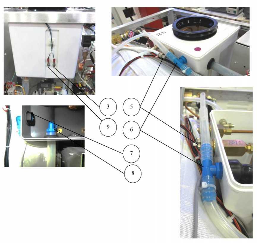
9 DESCRIPTION OF ITEMS No. Cat. No. Description 1 CTP or CTP CTP Miniature Relay 24VDC, for the air pump Relay, Solid State, 25A/24-280V, D2425, Crydom for heaters Page 7
10 3 ELE Power Supply 24VDC (1A) Reign Power 4 CTP or CTP ELE Water Pump Fuse 6 ELE Air Pump Fuse Miniature Relay 24VDC, for the water pump 7 ELE Power Supply 24VDC (1.1A) Lambda 8 CTP Control System Cooling Fan 9 ELE JP1 AC power to the control system and pumps 10 THE JP2 ceramic heater connector Main board The main board holds all the operating system software (application and settings). It handles interfacing with the operator through the keypad and display screen. The Main board also handles communications through the USB, printer and network ports. It controls all functioning of the machine through a ribbon cable connection to the IO board. Page 8

11 Ethernet Connector Keypad Connector Inputs Connector to IO Board Battery Analog inputs Power Supply Connector (24V DC) + - USB Connector Connector to LCD display Connector to printer I/O Board The I/O board handles all the inputs and outputs for the machine. The I/O board does not hold any software and receives all instruction from the Main board. Page 9

12 Digital outputs J14 J13 Analog inputs J11 J7 J2 Connection to MAIN Board Digital Inputs J Inputs and Outputs Analog inputs Analog inputs Description PT100-1 PT-100 chamber temperature input J2 Pressure 1 4mA-20mA chamber pressure input J7/1 Connector & pin Electrode 1 Water level in the chamber J11/1 Electrode 2 Water level in the reservoir J11/2 Page 10
13 Digital inputs Digital Inputs Description Connector& Pin Door 1 closed Door closed switch input J12/1 3.4 Troubleshooting the inputs: Connector J2 is for the first PT100 temperature input Disconnecting the J2 connector will result in the display showing Analog Input Error and no temperature reading. Connecting a PT100 simulator (Test -7) can confirm that the control system is receiving a temperature input signal Connector J7 is for the pressure sensor input Disconnecting the J7 connector will result in the display showing Analog Input Error and no pressure reading. Inputting 16mA (from an external source) should result in a display reading of 300 kpa +/- 3 kpa. This will confirm the control system is receiving a pressure input signal. Connector J11 is for the water sensor inputs J11-1 supplies 3.9 VDC to the water sensing electrode in the chamber. When water level rises to the tip of the sensor the signal is grounded and the computer knows the height of the water in the chamber. Note: When the sensor is grounded and the door is closed the door lock will be engaged. The icon Water in the Chamber will be displayed. Note: Dirt on the electrode can cause the system to fill the chamber with too little water, resulting in a failed cycle. Note: Dirt on the sensor can falsely indicate water in the chamber at the end of the cycle, causing the door to remain locked. The output at J11-1 or the tip of the electrode can be read as 3.9 VDC to ground. Shorting J11-1 or the tip of the electrode to ground will produce the Water in the Chamber icon on the display AND, if the door is closed, the door lock will be engaged. J11-2 supplies 3.9 VDC to one of the water sensing electrodes in the reservoir. The other electrode is connected to ground. When water Page 11
14 touches the electrodes the signal is grounded and the computer knows the height of the water in the reservoir. The output at J11-2 or the black wire of the electrode can be read as 3.9 VDC to ground, when the reservoir is empty. With the reservoir empty, shorting J11-2 to ground or shorting across the reservoir electrodes will remove the Fill Reservoir icon from the display. Note: Dirt accumulation between the electrodes in the reservoir can short the signal to ground and make the system think there is water in the reservoir when it is empty. With the reservoir full, removing either the black or green wire from the connector on the outside of the reservoir will produce the Fill Reservoir icon on the display. Connector J12 contain the DC input from the door switches J12-1 is the input for both door switches. The door switches are wired in series so if either one is open the Door Open displayed. icon will be J12-1 needs to see +24 VDC to know the door is closed Digital outputs - Digital Outputs Door unlock Chamber heat Water pump relay Air Pump relay Description Energizes the door lock solenoid and unlocks the door Energizes the SSR that controls the chamber heaters Energizes the water pump relay that controls the fill solenoid & the water pump Energizes the air pump relay that controls the air pump solenoid & the air pump Connector & Pin J13/4 J13/6 J13/10 J13/12 Slow exhaust Energizes the slow exhaust valve J14/6 Fast exhaust Energizes the fast exhaust valve J14/8 Page 12
15 3.5 Troubleshooting the outputs: Connector J13 contains the DC outputs Utilizing the Test Digital Outputs option (under technician code 0321) allows you to turn the outputs on and off to verify the component operation. With the J13 connector in place, inserting the probe from a DVM into any of the listed positions will show a reading of +24VDC with respect to ground when that component is toggled on. J13-1 is the +24 VDC input to the circuit board from the power supply at the top of the electronic box. J13-4 is the DC output to the electronic door lock solenoid J13-6 is the DC output to the SSR that controls the heating elements J13-10 is the DC output to the mechanical relay coil #1 that controls the water pump and water fill solenoid. J13-12 is the DC output to the mechanical relay coil #2 that controls the air pump and air pump solenoid. Connector J14 contains the AC outputs Utilizing the Test Digital Outputs option (under technician code 0321) allows you to turn the outputs on and off to verify the component operation. With the J14 connector in place, inserting the probe from a DVM into any of the listed positions will allow a reading of +18VAC with respect to the red lead on JP3 as the component is toggled on and off. J14-1 is the 18 VAC input to the circuit board from the toroidal transformer at the back of the machine. J14-6 is the AC output to the top/slow exhaust solenoid J14-8 is the AC output to the fast exhaust solenoid Power Supplies Toroidal step down transformer The incoming 120VAC is stepped down to 18VAC by the toroidal transformer at the back of the unit. Since it is a step down transformer if the 120 volt input fluctuates up or down then the 18 volt output will also fluctuate up and down. Page 13


16 The only function of the transformer is to supply voltage for the coil of the solenoid valves. Even though this transformer is protected by the ON/OFF Circuit Breaker it also has an input and output fuse. The input fuse is a 5x20 mm T1AL time delay fuse The output fuse is a 5x20 mm F5AL fast acting fuse If the input or output fuses on the transformer fail then the solenoids will not function even though the rest of the machine will PS-1 24VDC Power Supply (at the top of the electronic box) PS-1 provides 24VDC to the Main board, the I/O board, the pressure transducer and the electronic door lock, door switches and the relays which control the water filling, drying and heating. The PS-1 has an adjustment screw that is set at the factory and should not be field adjusted. This power supply is protected by the main ON/OFF Circuit Breaker located on the right side of the front panel PS-2 24VDC Power Supply (at the bottom of the electronic box) PS-2 provides power for the fan and the optional printer. The PS-2 has an adjustment screw that is set at the factory and should not be field adjusted. This power supply is also protected by the main ON/OFF Circuit Breaker located on the right side of the front panel. Page 14


17 3.5.2 Mechanical Relays There are two mechanical relays, one for each of the pumps (air pump and water pump). The relays are in sockets so they can be easily replaced. The relays have two sets of contacts. One set turns the pump on and off. The other set allows the solenoid valve for that pump to open and close. The relay coil receives a 24VDC signal voltage from the I/O board and the contacts close to allow the 120VAC to pass through and operate the pump. At the same time it also allows the 18VAC to pass through and open the solenoid valve. Page 15

18 3.5.3 Sold State Relay The SSR is used to control the heating elements The SSR receives a 24VDC signal voltage from the I/O board and closes to allow the 120VAC to pass through to the heaters. The SSR is located in the electronic box below the mechanical relays AC solenoid valves There are 4 solenoid valves that operate on 18 volts AC. Reading across the orange and black wire at the coil connection will show 18VAC when the coil is on and about 10VAC when it is off. The Slow and Fast Exhaust solenoids work directly off the I/O board J14. The Water Pump and Air Pump solenoids work through the mechanical relays for the pumps Water Pump The Water Pump is a 120VAC pump and works off Mechanical Relay #1. The line voltage to the pump is protected by fuse #1 (2A) Air Pump The Air Pump is a 120VAC pump and works off Mechanical Relay #2. The line voltage to the pump is protected by fuse #2 (2A) Electronic Door Lock This unit is mandated to have an electronic door locking system. The door lock is a 24VDC solenoid with a spring loaded locking pin. When the solenoid is activated it retracts the pin and the door is unlocked. The locking solenoid is mounted in a vertical position with the spring loaded pin at the top. Page 16
19 3.5.8 Door Switches The door has and upper and a lower door switch to ensure that the door is properly closed before the cycle can start. The door switches are in series so if one switch is open the door is considered unlocked and the cycle will not start Heaters There are two 120 volt 700 watt heaters that wrap around the chamber. They have wire leads that are connected in a ceramic block by the electronic box. Page 17


20 1 1 1 THE JP2 ceramic heater connector Temperature Sensor The temperature sensor is a PT100 mounted inside the chamber at the bottom rear Pressure sensor The pressure sensor is a Tecsis P3297 with an output of between 4 20ma. It is located at the back of the machine and is connected by copper tubing to the rear manifold at the top of the chamber. Page 18
21 Safety Thermostats There are two safety thermostats. The Cut-Off and the Temperature Safety Thermostat. They are mounted at the back of the machine with probes that are mounted under the rear most heating element. They are connected in series and monitor only the heating element circuit Fuses There are four fuses. 1. Two fuses for the Toroidal Transformer, one input and one output. The input fuse is 1A Time Delay (T1AL) and the output fuse is a 5A Fast Acting (F5AL). 2. Two fuses for the pumps. One for the air pump and one for the dry pump. The pump fuses are 2A each Circuit Breaker The Circuit Breaker is also the On/Off switch and is located on the right side of the machine at the front. Page 19
22 4 Checking and Changing Parameters and Other Data This section shows how to access system data and modify parameters. The Cycle Parameters directory containing parameters for controlling the sterilization process is locked for programs 1 thru 4 and not available for modification from the default values (except for drying) Program 5 is a cleaning program and all parameters are locked. Program 6 is a calibration program for use by a technician and all parameters are locked. Two programs are available for the user to modify as needed, Custom A and Custom B. These custom programs are not FDA cleared and it is the user s responsibility to validate these programs. Spore testing is your only assurance of complete sterilization. Once entering the programming mode, the technician will see and have access to the following directory items. Directory Quick Options (does not require login) see sec. 4.3 in this manual and 7.1 in the Operator Manual Main Menu (requires login) see sec. 4.4 Cycle Parameters for all programs individually Cycle Parameters applicable only for Custom programs (except Dry Time) System Parameters See Subdirectory Add extra dry time Export to USB Print cycles Version information Start cycle by clock Set date and time Login Exit Temperature sensors (not used) Displayed Inputs Drying (see Operator Manual) Cycle Parameters (see Operator Manual) Print Rate All (see Operator Manual) Print Rate Sterilization (see Operator Manual) Page 20
23 sec. 4.7 Inputs/Outputs Maintenance See sec. 4.9 Advanced Options Version Handling Screen Saver (see Operator Manual) Pressure Calibration High (not used) Pressure Calibration Low (not used) Temperature Calibration High (not used) Temperature Calibration Low (not used) Water Quality Level Cycle Print Gap (see Operator Manual) View digital inputs state View digital outputs state Test digital outputs View analog inputs state Analog inputs calibration Export gain and offset to USB Input gain and offset from USB Reset atmospheric pressure Test RTC Printer test (see Operator Manual) Print all gain and offset(see Operator Manual) Enable cycles Set language (English) Set temperature units (ºF) Set pressure units (Psig) Duplicate cycle Delete custom cycles Set external IP-address (DHCP) Import application from USB Import all settings from USB device Import application and settings from USB Return to factory default settings 4.1 Browsing through the menus The following example will show you how to browse through the directories and subdirectories and change parameters. This is all done by using the three button keypad. Page 21
24 The keypad functioning is a follows: 1. Pressing the UP and DOWN keys simultaneously for 1-2 seconds will allow access to the menu options. 2. Use the Up and Down keys to advance the cursor and scroll through the menu. 3. Press the Start/Stop key to select and enter the menu selection that is highlighted. 4. Repeat steps 1 and 2 to enter the next menu selection until you get to required screen. 5. When no menu selections are available, as in a parameter screen, the keys are reversed. The Start/Stop key will advance the cursor and the Up or Down key will select the highlighted item. Below are the example screens for the following menu (this option will normally require a Technicians code 0321 to login) Cycle Parameters\ Drying\ Dry Time: Note: To exit every screen and to return to the previous screen (to move one level up): Page 22
25 - or- move the cursor to Exit by pressing the UP or DOWN keys and then press the Start/Stop key. press the UP and DOWN keys simultaneously. In the next section you will see how to make changes to a parameter. 4.2 Modifying any Parameter You have browsed through the menus and reached the parameter changing screen as explained above. Now you can change the selected parameter as needed. To do so: 1. Enter the required value as follows: Press the Up and Down keys to change the value of the digit. Press the Start/Stop key to move the cursor to the next digit to the left. 2. When finished, press the Start/Stop key repeatedly until you move the cursor to Set. 3. Press the Up or Down key to confirm the new value and to exit the parameter changing screen. Below is the typical parameter changing screen: Note: Please note the maximum and minimum values for this parameter shown on the screen. Your value must be within these boundaries. Page 23
26 Below is the example of changing the Dry time parameter on the screen used in the previous section: Note: To exit every screen and to return to the previous screen: Page 24
27 - or- move the cursor to Exit by pressing the UP or DOWN keys and then press the Start/Stop key press the UP and DOWN keys simultaneously 4.3 Quick options screen When the autoclave is on and no cycle is running, press the Up and Down keys simultaneously to enter the Quick options screen. The Quick options menu offers easy access to the most frequently used features. All other options require logging in and their availability depends on your level of access (user code 0001 or technician code 0321). Below you can find instructions how to login and enter the Main menu. Section 7.1 above explains how to browse through the menus; section 7.2 explains how to change a parameter. Note: A complete explanation of the Quick Options menu can be found in the EZPlus Operator Manual. 4.4 Logging in and entering the Main menu Below you can find instructions how to login and enter the Main menu. Section 4.1 above explains how to browse through the menus, section 4.2 explains how to change a parameter. When the autoclave is on and no cycle is running, press the up and down keys simultaneously to enter the Quick Options screen (see 4.3). On this screen you can proceed to login.to login as technician: Page 25
28 1. On the Quick Options screen, choose login. Select user screen appears. 2. Choose Technician, then press the Start/Stop key to enter. The following screen will appear: 0000 is displayed on the screen with the cursor flashing on the right digit. Set the code to You will get to the Main menu. Page 26
29 Below is the list and the explanation of the options available on the Main Menu. 4.5 Directories and subdirectories Bacsoft control panel provides an interface that consists of control screens available through an easy scrollable menu tree. To learn how to scroll through the menus, change the parameters, and perform some other functions using our three-button keypad, see 4.1 and 4.2. The following chapter explains meaning and usage of the control screens. 4.6 Cycle Parameters (cycle specific) Temp Sensor this option is not used in this machine Display Inputs The screen space on the right consist of three display positions. The display position of the temperature and pressure can be changed using this parameter Drying Allows for changing the amount of drying time. The Wrapped and Handpiece cycles cannot be reduce below their default valve. 4.7 System Parameters This menu is listing the system parameters that are the same for all cycles. Browse to the following folder: Page 27

30 Main menu\system parameters You will see the following screen: Brief description of system parameters Print Rate all defines the printing rate during all stages of the cycle except the sterilization stage. This feature requires a printer to be installed. Print Rate Sterilization Defines the printing rate during the sterilization stage. This feature requires a printer to be installed. Screen Saver defines the time interval from the last use of the Keypad until the screen saver is activated. Setting this parameter to 0 minutes will disable the screen saver Pressure Calibration High not used in this machine Pressure Calibration Low - not used in this machine Temperature Calibration High - not used in this machine Temperature Calibration Low - not used in this machine Water Quality Level used to set the acceptable quality of the water in the water reservoir. On a scale of , 0 being the poorest quality and 4095 being the best quality. The default setting is 0. Cycle Print Gap Defines the number of blank lines to advance at the end of the cycle. Page 28

31 4.8 Inputs/Outputs It is important for the technician to control the system down to the level of specific inputs and outputs. Viewing the outputs state at specific stages of the cycle helps you diagnose the malfunctions. You can also test and calibrate inputs and outputs. These options will function with any program selected and can be viewed while the cycle is running. Below is the typical screen for viewing/testing the inputs/outputs. Below is the instruction for working with inputs/ outputs View digital inputs state This screen shows in real time if the door is open or closed. A checked box indicates the door is closed. Page 29
32 4.8.2 View digital outputs state This screen shows the status of each component in real time. A check mark means the component is energized. This screen can be viewed while a cycle is running and will show the various components cycling on and off Test digital outputs Attention! Violating the following instructions may endanger the technician and may cause severe damage to the autoclave! Caution Do not operate the heating elements for an extended period of time. This can damage the heaters, and cause possible personal injury. Caution Do not operate the water pump for an extended period of time. This can cause damage to the pump. Exiting this screen will automatically set each component back to its normal state. Page 30
33 This test program allows the technician to activate and deactivate various components of the autoclave in order to evaluate that components performance. 1. Turn on the autoclave and press the Up and DN keys simultaneously. This will bring up the Quick Options Menu. 2. Scroll to Login and press the Start/Stop key. 3. Select Technician and press the Start/Stop key. 4. Enter the code Scroll to Set and press the Up key. 5. Scroll to Inputs Outputs and press the Start/Stop key. 6. Scroll to Test Digital Outputs and press the Start/Stop key. 7. A list of outputs will appear 8. Scroll to the item and press the Start/Stop key to check the box and turn on the component 9. Press the Start/Stop key again to uncheck the item and turn off the component 10. When finished Exit out of the menu 11. The components will automatically return to their normal state View analog inputs state In this menu you can view, at any stage, the values of the analog inputs at the moment. This screen allows for monitoring the chamber temperature, chamber pressure, chamber water lever and mineral free reservoir water level. Chamber Temperature will be displayed in the same units as the main screen display Chamber Pressure will be displayed in the same units as the main screen display. Page 31
34 Chamber Water and Reservoir Water indications at or close to 4095 indicate that no water is being sensed. Chamber Water and Reservoir Water indications at or close to 0 indicate that water is being sensed. This screen can be viewed while a cycle is running Analog inputs calibration This screen allows for calibrating each of 4 analog inputs. Scroll up or down the screen and press the Start/Stop key to select the device to calibrate. See sec 5 Calibration 4.9 Maintenance Maintenance procedures provided by Bacsoft software allow you additional tests and USB input/output options. Browse to the following folder: Main menu\maintenance You will see the following screen listing the maintenance options: Below is the instruction for autoclave s maintenance menu Export gain offset to USB In this menu you can export, to a USB flash drive, the gain and offset that was calculated as a result of calibration. The gain and offset values are the numerical representation derived from calibration. Note: The USB flash drive needs to use FAT formatting. Page 32
35 1. Insert the USB device into the USB Socket located behind the printer door. (See sec. 4 in the Operator Manual) 2. Move the cursor to Export gain offset to USB 3. Press the START/ STOP key. The following screen will be displayed: 4. Remove the USB device from the USB socket Import gain and offset from USB In this menu you can import, from a USB flash drive, the gain and offset that was calculated as a result of calibration. The gain and offset values are the numerical representation derived from calibration. Note: The USB flash drive needs to use FAT formatting. 1. Insert the USB device into the USB Socket located behind the printer door. (See sec. 4 in the Operator Manual). 2. Move the cursor to IMPORT gain offset from USB 3. Press the START/ STOP key. The following screen will be displayed: Page 33

36 4. Remove the USB device from the USB socket Reset atmospheric pressure This is an option to manually reset the Atmospheric pressure parameter. Note: The atmospheric pressure parameter needs to be reset after recalibrating the unit s pressure. Note: Please reset the atmospheric pressure when you install the autoclave for the first time, and each time you relocate the autoclave. Note: The atmospheric pressure parameter is set Automatically by the machine when; 1. Each time the machine is turned on and 2. The door is open for at least 2 minutes and 3. The chamber temperature is below 113ºF (45 ºC) However, this parameter can be manually reset by using this option. Two conditions need to be meet to correctly reset the atmospheric pressure. 1. The door needs to be open for 2 minutes 2. The chamber temperature needs to be below 113ºF (45ºC) Move the cursor to Reset atmospheric pressure then press the START/ STOP key. The following screen will appear: Page 34

37 4.9.4 Test RTC The EZPlus system contains two internal clocks (RTC & Windows) that are used to validate the time of the sterilization cycle. If these clocks are out of sync by more than four seconds the cycle will fail. 1. The RTC. This clock is charged from the battery on the main board. It keeps track of the time even if the power is off. 2. The windows clock restarts each time the machine is turned on. The clock is updated from the RTC. 3. When pressing start to run a cycle, the 2 clocks are synchronized. During the cycle, there are two readings from the clocks. One when sterilization starts and the other when the sterilization ends. If the difference between the clocks is more than 4 seconds, the cycle will fail TIME ERROR The Test RTC option allows for testing the clocks. Set the number of minutes for the test and enable Start by using the Up key. The test time should be set for the same time as the sterilization cycle being used. (i.e. 4 minute sterilization 4 minute test, 30 minute sterilization 30 minute test). The following screen will appear: Page 35
38 1. Set the time interval as desired using the Up/Down keys. 2. Then using the Start/Stop key move the cursor to start and press the Up key. At the end of the test, the following screen will appear: 3. At the end of the test using the Start/Stop key, move the cursor to Exit and press the Up key. If the test fails then: 4. Go to the Set Date and Time option and set the correct date and time. Be sure to enable SET using the Up key even if no adjustment to the date or time is needed. 5. Change the battery on the Main board 6. Change the Main board Page 36
39 4.9.5 Printer test In this menu you can check the normal function of the printer. The printer will print the list of error messages. (see also the Operator Manual) Print all gain and offset In this menu you can print the gain and offset values for Chamber Temperature, Chamber Pressure, Chamber Water Level, Mineral Free Water Level. (see also the Operator Manual) 4.10 Advanced Options Advanced options menu contains options for customizing the EZPlus autoclave Enable/Disable cycles This option allows for removing cycles from the rotation on the main screen. Use the Up/Down keys to select the program to be removed and press the Start/Stop; key to uncheck that program. That program remains in the machine, but is removed from the rotation. To return the program to the rotation just restore the check mark. Note: The current cycle cannot be disabled. A different cycle must be selected prior to entering the ENABLE PROGRAMS subdirectory. In order to exit this screen move the cursor to EXIT by pressing the Up/Down keys and select it by pressing the Start/Stop key. Page 37

40 Set Language In this menu you can choose the language for all the interface screens: menus, cycle information, system messages. This option allows for changing the language on the main display, all the menu screens and the print out. The only text that does not change are the program headings. Changing the language will cause the machine to reboot. Note: There are more languages than you see on the screen above. Just scroll down to see more. 1. Move the cursor to the desired language and check it. The following screen will appear: Page 38
41 The machine will be restarted and the main screen (current cycle) will appear in the chosen language. Caution: Do not set a language you cannot read! Set temperature units This option allows for selecting the temperature units to be displayed and printed, either Celsius or Fahrenheit. In order to change the temperature units move the cursor to the desired temperature units and press the START/STOP key. Changing the temperature units will cause the machine to reboot Set pressure units This option allows for selecting the pressure units to be displayed and printed, kpa, Psia, Psig, BarA, BarG. In order to change the pressure units move the cursor to the desired pressure units and press the START/STOP key. Changing the pressure units will cause the machine to reboot Duplicate cycles In this menu you can create a copy of any of the programs on the list with all its current parameters. Once created this new program becomes a custom program and as a custom program all the settings are available for modification. Page 39
42 1. Using the Up/Down keys, move the cursor to the cycle you want to duplicate. 2. Press Start/Stop to select the cycle. A custom program has been created with the same settings. 3. You will be able to change the settings later. The following screen will appear: 4. Using the Up/Down keys, to select letters and numbers, and the Start/Stop key, to advance, give this new program a name. 5. Advance to SET and press the Up key to save the program and exit. 6. Pressing Exit before Set will not save you changes. 7. Exit the menus until you get to the main screen. 8. Select your newly created program. Note: you can select the program only when the autoclave door is open. Page 40


43 9. Login again as Technician (see 4.4). 10. In the main menu, select Cycle parameters and enter the Cycle Parameters screen. The following screen will appear: Now you can alter the cycle parameters as desired. Page 41

44 Delete custom cycles In this menu you can delete any of the custom cycles that appear on the list. 1. Use the Up/Down key to move the cursor to the cycle you wish to delete. 2. Press Start/Stop key to select/deselect the cycles. 3. Move the cursor to Delete selected cycles and press Start/Stop key to delete. 4. The selected custom cycle is now deleted Set external IP address This option is for use with Tuttnauer s R.P.C.R. monitoring software and allows for setting the IP address in order to connect to a local network that does not have a DHCP server. Page 42
45 If the local area network has a DHCP server the IP address needs to be set to all zeros and the connection process will be automatic Version handling The version handling menu provides tools to import, export, and restore the autoclave software. There are two parts to the Tuttnauer autoclave operating software. 1. The Application this part of the software tells the machine what kind of sterilizer it is.(table top, no generator, etc.) 2. The Settings this part of the software tells the machine what programs it has and the parameters for each program (Wrapped, Unwrapped, sterilization temperature, sterilization time, etc ) The following options are available Import application from USB This option may be needed if in the future there is an application upgrade available. Software is imported from a USB flash drive. 1. Insert the USB device with the Application software into the USB slot on the front of the machine. 2. Select Import application from USB and press the Start/Stop key 3. The system will prompt you to confirm import, showing the Application version to be imported. Page 43

46 4. The cursor will be blinking on Confirm. 5. Press the Start/Stop key to confirm. 6. Selecting Cancel will cancel the import. 7. The application will be imported from the USB device. 8. Importing a new application will cause the machine to reboot. Page 44

47 Import all settings from USB device This option may be needed if in the future there are upgrades available for cycle parameters. Software is imported from a USB flash drive. 1. Insert the USB device with the Settings software into the USB slot on the front of the machine. 2. Select Import settings from USB and press the Start/Stop key 3. The system will prompt you to confirm import On this screen, you will see the model name and parameters checksum of the settings saved on the USB device. 4. The cursor will be blinking on Confirm. 5. Press the Start/Stop key to confirm. 6. Selecting Cancel will cancel the import. Page 45
48 The following screen will appear: 7. Keep old serial number and Keep old calibration will be checked. They should remain checked. 8. Use the Up/Down keys to advance to Import 9. Use the Start/Stop key to import the settings 10. Selecting Cancel will cancel the import. 11. Importing new settings will cause the machine to reboot. The following screen will appear All the autoclave settings will be imported from the USB device Import application and setting from USB 1. This option allow for importing the Application and Settings software at the same time. Page 46
49 2. This option may be needed if in the future there are upgrades available for application and settings 3. Software is imported from a USB flash drive Return to factory default settings This option allows for resetting all the personal software settings back to the default factory settings. Note: This includes the calibration. The machine will have to be recalibrated after resetting. 1. Move the cursor to Confirm and press Start/Stop. 2. The default factory settings will be restored. 3. Selecting Cancel will cancel this operation. The following screen will appear Page 47
50 4.12 Cycle parameters This directory enables the technician to see and change all the cycle parameters for any custom cycle including Custom A and Custom B cycles. To modify a program it is necessary to select that program from the Main Screen before entering the "MAIN MENU" directory After loging in and selecting Cycle Parameters the following screen will be displayed. The Cycle parameters directory includes the following subdirectories Subdirectory Temperature sensors Displayed inputs For custom programs only Create Pulse Property Chamber Temperature First Second Third Pulse A Count Pulse A Stay Time Pulse A Low Pressure Pulse A High Pressure Pulse B Count Pulse B Stay Time Pulse B Low Pressure Pulse B High Pressure Pulse C Count Page 48
51 Keep Heat Heating Sterilization Pulse C Stay Time Pulse C Low Pressure Pulse C High Pressure Pulse D Count Pulse D Stay Time Pulse D Low Pressure Pulse D High Pressure Temperature 1 stay Temperature 1 stay time Temperature 2 stay Temperature 2 stay time Sterilization Temperature Sterilization Temperature Sterilization Time Exhaust Exhaust Mode Drying Ending Global Dry Time Dry Heat On 1 Dry Heat Off 1 Dry First Stage Time Dry Heat On 2 Dry Heat Off 2 Add Dry Time End Temperature Check RTC Jacket Temperature The following sections explain the meaning and usage of the individual parameters under cycle parameters. Note: The following 3 options are available in the FDA Cleared programs as well as the Custom Cycles; Temperature Sensors Page 49
52 Displayed Input Drying Temperature Sensors EZ9Plus & EZ11Plus use only the Main Chamber Temperature sensor. Displayed inputs This option allows for deciding which input values will be shown on the display and the order in which the inputs are displayed. There are three display positions. The default for each program uses only the first two. They are the Chamber Temperature and the Chamber Pressure. Additional inputs, that can be displayed, are Chamber Water and Mineral Free Water. Using the Up/Down keys, choose the input position to be modified and press the Start/Stop key. Page 50
.")
53 1. The following screen will appear: 2. Using Up/Down keys, move the cursor to the desired input and choose it by pressing Start/Stop Create Pulse This subdirectory allows for setting the parameters for each pulse of the program (see Operator Manual for more detailed explanation). Page 51
54 4.13 Keep Heat Keep Heat offers the option of locking in a specific temperature for a specified amount of time at two steps in the process. Below are instructions for changing the Temperature and Temperature stay time Temperature 1 stay Using the Up/Down keys, choose the Temperature (1 or 2) to be modified and press the Start/Stop key. The following screen is displayed Page 52
55 Use the Up/Down keys to modify the temperature making sure to stay within the Min/Max limits displayed Temperature 1 stay time Using the Up/Down keys, choose the Temp Stay Time (1 or 2) to be modified and press the Start/Stop key. The following screen will be displayed Page 53
56 Use the Up/Down keys to modify the minutes making sure to stay within the Min/Max limits displayed Temperature Heat Gap This parameter sets the additional temperature above the stay temperature in keep heat stage. For example, if the stay temperature parameter is set for 220 F and the Temperature Heat Gap parameter is 3 F, it will keep the temperature around 223 F. This will prevent the temperature from dropping below the set temperature of 220 F 4.14 Heating This subdirectory allows for setting the target sterilization temperature for the cycle. Once this temperature is reached the Sterilization phase can start. The Sterilization Temperature parameter in Heating must be equal to the sterilization temperature parameter of the sterilization phase. The Heat Pressure Safe Gap parameter is not active in the EZ9Plus and EZ11Plus units. Page 54
57 4.15 Sterilization This screen shows the sterilization temperature and time for the selected program Sterilization Temperature This parameter defines the sterilization temperature for the cycle. Select this parameter and use the Up/Down keys to modify the temperature making sure to stay within the Min/Max limits displayed. Page 55
58 Sterilization Time This parameter defines duration of the sterilization stage for the cycle. Select this parameter and use the Up/Down keys to modify the time making sure to stay within the Min/Max limits displayed Exhaust This parameter defines options available for the exhaust stage Exhaust Mode After selecting Exhaust use the Up/Down keys to select the number that corresponds to the type of exhaust desired. 1 Fast exhaust 2 Slow exhaust until the pressure is lower than 30kPa + atmospheric then fast exhaust. Page 56
59 3 Slow exhaust 4 Fast exhaust is used if cycle has run with no errors. If the cycle fails before sterilization has been completed then slow exhaust. (This mode is usually used on a bio cycle, but can be used whenever this logic is needed) Drying This subdirectory lists the parameters available for modifying the drying phase. There are two stages to the drying phase each with their own set of controlling parameters. Below are explanations and instructions for each of the drying parameters Dry Time Dry Time is the total drying time of the drying phase of the program. The total drying time is divided into two stages. In each stage the, on and off, duty cycle of the heating can be controlled separately Dry Heat On 1 This parameter defines how long the heating elements will be ON for the first stage of drying Dry Heat Off 1 This parameter defines how long the heating elements will be OFF for the first stage of drying. Page 57
60 Dry First Stage Time This parameter defines duration of the first stage of drying. The second stage of drying will be equal to the remaining dry time. (Dry Time Dry first stage time) Dry Heat On 2 This parameter defines how long the heating elements will be ON for the second stage of drying Dry Heat Off 2 This parameter defines how long the heating elements will be OFF for the second stage of drying Add Dry Time This parameter allows you to add additional Drying Time to the total Dry time for the current cycle. The total dry time will be divided as per the settings under the Dry Time parameter Ending This subdirectory allows for setting the temperature at which the cycle is officially completed End Temperature This parameter defines the temperature when the cycle ends. The cycle will not end and the door will not open until the autoclave chamber has cooled down to this temperature Global This subdirectory defines the global cycle parameters. Page 58
61 Check RTC This option allows for turning on or off the time validation of the cycle and is only available in the Custom Cycles. Note: It is a requirement that the time validation be functional. During the cycle, there are two readings from the two clocks. One when sterilization starts and the other when the sterilization ends. If the difference between the clocks is more than 4 seconds the cycle will fail displaying a message TIME ERROR. If the Check RTC parameter is 1 (default in EZPLUS machines) the time validation will be turned on If the Check RTC parameter is 0 the time validation will be turned off and no error message will be generated Jacket Temperature This parameter defines the pre-heat temperature of the chamber. This feature is only available for modification in the Custom cycles. The system is ready, but will not start the cycle until the chamber reaches the pre-heat temperature. The selected cycle will start automatically when the temperature is reached. Page 59
62 5 Calibration 5.1 Calibration It is recommended that all calibrations be performed using Celsius and KPA Calibrations can be done while the machine is running a cycle Calibrations are required ONLY when one of the following components is changed. 1. Main board 2. I/O board 3. Temperature sensor 4. Pressure sensor Sensors to calibrate Chamber Temperature Chamber Pressure Reads the temperature in the chamber. Reads the pressure in the chamber. Note: Upon competition of the calibration the Atmospheric Pressure parameter needs to be reset. Required equipment for calibration Reference temperature tool reading in Celsius Reference pressure tool reading in kpa. ¼ BSP adaptor (for the validation port) Or Tuttnauer s calibration tool Test 13. This test device is set to display ºC and kpa. Page 60


63 TEST Calibration Port Chamber port: Located at the rear of the chamber for measuring temperature and pressure in the chamber, Install the test equipment as shown. Make sure all nuts are tight to prevent leaks. Position the temperature probe so it is in the same general location as the machine temperature sensor. Page 61


64 5.3 Accessing the Calibration mode First select the Calibration cycle The Calibration Cycle is designed with an extra-long sterilization time Now press the UP and DOWN keys, on the keypad, simultaneously to begin accessing the calibration software. The screen that will appear is the Quick Options screen Scroll to Login and press Start/Stop Page 62
65 The screen that will appear is the Select User screen. Scroll to Technician and press Start/Stop Using the Up/Down keys to enter the digits and the Start/Stop key to advance to the next digit enter the Technicians code 0321 Page 63
66 Advance to Set and press the Up key. The next screen will be the Main Menu screen. Scroll to Advanced Options and press Start/Stop. The Advanced Options screen will appear Scroll to Set temperature units and press the Start/Stop key Celsius will be blinking, press the Start/Stop key. The system will reboot and the display will be in Celsius. Repeat this procedure for changing the pressure to kpa. Page 64
67 When finished reenter the Main Menu and proceed as follows Scroll to Inputs/Output and press Start/Stop Then scroll to Analog Inputs Calibration and press Start/Stop The Calibrate analog inputs screen will appear. Page 65
68 Scroll to the input to calibrate and press Start/Stop The Calibration Options screen will appear. Page 66
69 Scroll to Calibrate analog input and press Start/Stop The calibration screen will appear It is recommended that all calibrations be performed using Celsius and KPA Calibration is performed using ACTUAL readings from your test equipment. This is a typical calibration screen: There are two rows of data each row having two values. Read High, Actual High / Read Low, Actual Low. High end of the range Low end of the range Read High - this is what the sterilizer thinks the HIGH end temperature or pressure reading is. As shown on the display screen Actual High - this is what is read from the calibration device showing the HIGH end temperature or pressure reading. Read Low - this is what the sterilizer thinks the LOW end temperature or pressure reading is. As shown on the display screen Actual Low - this is what is read from the calibration device showing the LOW end temperature or pressure reading. Page 67

70 Readout from display screen Actual value from test equipment Entering the values from the test device and the screen readings then selecting SET will instruct the machine to calibrate that sensor. 5.4 Calibration Procedure The EZPlus sterilizer should be on and in the Calibration cycle. The above preliminary steps should have been completed. Calibrate the LOW end of the temperature. With the door of the machine closed and the temperature stabilized record the Actual temperature and Read temperature. Page 68
71 Enter these values into the appropriate locations on the Calibrate Analog Input screen. Using the Up/Down keys to change the digit value and the Start/Stop key to advance to the next position. Advance to Set and press the Up key the system will recalibrate the low end of the temperature. Calibrate the LOW end of the pressure. With the door of the machine open record the Actual pressure and Read pressure. Enter these values into the appropriate location on the Calibrate Analog Input screen. Using the Up/Down keys to change the digit value and the Start/Stop key to advance to the next position Advance to Set and press the Up key the system will recalibrate the low end of the pressure. Calibrate the HIGH end of the temperature and pressure. With the door of the machine closed and the Calibration Cycle selected, press the Start/Stop key. Allow the machine to reach sterilization and record the Actual temperature and Read temperature. Record the Actual pressure and Read pressure. While the cycle is running, reenter the Analog Input Calibration screen, first for temperature then pressure. Enter these values into the appropriate location on the Calibrate Analog Input screen. Using the Up/Down keys to change the digit value and the Start/Stop key to advance to the next position Advance to Set and press the Up key the system will recalibrate the high end of the input selected. The machine temperature must be within +/- 0.3ºC of the temperature shown on the calibration device. The machine pressure must be within +/- 3 kpa of the pressure shown on the calibration device. After calibrating the temperature and pressure consult the Saturated Steam Table (below) to confirm that the temperature is also within +/- 0.3ºC of the pressure reading according to the table Page 69
72 AND the pressure is also within +/- 3 kpa of the temperature reading according to the table. Make adjustments as appropriate. Note: If during the Heating phase the Slow Exhaust releases steam more than twice this indicates the temperature and pressure are out of balance. Consult the Saturated Steam Table (below) for the proper temperature / pressure correlation and make an adjustment, while the cycle is running. This will allow the cycle to move to the sterilization phase where the final calibration can be done. When the calibration is completed go back to Advanced Options and reset the temperature and pressure to ºF and psig also reset the Atmospheric Pressure parameter. If the temperature or pressure cannot be calibrated and the calibration was performed correctly then replace the device that will not calibrate. 5.5 Saturated Steam Table psia InHg F Bar kpa C psia psig F Bar kpa C psia psig F Bar kpa C Page 70
73 Page
74 Page 72 C kpa Bar F psig psia C kpa Bar F psig psia
75 Page C kpa Bar F psig psia C kpa Bar F psig psia
76 Page
77 Page 75 C kpa Bar F psig psia C kpa Bar F psig psia
78 Legend: psia absolute pressure in psi Psig gauge pressure in psi kpa absolute pressure in kilo-pascal InHg pressure (vacuum) in inch-mercury In the event of an error in calibration the calibration can be returned to the previous settings Restore last calibration. The calibration can then be tried again. In the event of a serious error in calibration the unit can be set back to the factory default calibration Restore default calibration. The calibration can then be tried again Restore last calibration There is an option to restore the gain and offset values set at previous calibration. 1. On the calibration options screen, choose Restore last calibration. The following screen will appear: Page 76
 gain and offset values 1.")
79 2. Using the up and down keys, move your cursor to confirm and press Start/Stop. The following screen will appear: Restore default calibration There is an option to restore the default (factory) gain and offset values 1. On the calibration options screen, choose Restore last calibration. The following screen will appear: Page 77


80 2. Using the up and down keys, move your cursor to confirm and press Start/Stop. The following screen will appear: Calibrating the chamber water level N/A Calibrating the mineral free water level N/A Page 78
81 6 Maintenance, Testing and Replacement Procedures 6.1 Preliminary Operations for Each Technician Call 1. In order to maintain efficient service, the technician must perform the following: a. Cleaning or replacing the following if necessary; Chamber, trays and trays holder. (Not covered under warranty) Door gasket (Not covered under warranty) Filters. (HEPA filter not covered under warranty) Bottom parts and plungers of the solenoid valves. (Not covered under warranty) Water reservoir.(not covered under warranty) b. Visual inspection for leaks or corrosion in the piping elements, plungers and solenoid valves. c. Fastening loose screws and piping joints. d. Visual inspection of the wiring. e. If circuit boards, pressure or temperature sensors were replaced then calibration and logging the calibration of the temperature and pressure see sec 5 Calibration. 2. After completing the work, the technician must perform the following cycles: A 270ºF (132ºC) cycle with full load. Note: The warranty does not cover cleaning or maintenance. These procedures are the responsibility of the equipment owner. 6.2 Safety tests after repair ATTENTION! After every repair or dismantling of the enclosure, the autoclave must pass two electrical safety tests administered by the Technician. The following shall be performed: 1. Enclosure Leakage Current Test. Equipment needed Megohmmeter Page 79

82 The test procedure is as follows: 1. Connect the electrical cord to the autoclave. 2. Do not connect to a power source. 3. Turn on the main switch on the right side of the autoclave. 4. Short-circuit the L and N pins on the cord's plug. 5. Connect the Short-circuit pins to the L pole on the electrical tester. 6. Connect the earth pins to the earth pole on the electrical tester. 7. Impose an electrical potential of V on the tested autoclave. The insulation resistance should be at least 2 MΩ. The test is successful if there was no leakage. 2. Protective Earth Impedance Test Equipment needed ohm meter The test procedure is as follows: 1. Connect the electrical cord to the autoclave. 2. Do not connect to a power source. 3. Connect the grounding pin of the power cord plug to one pole of the Ohmmeter. 4. Connect any other metallic part (preferable the metallic part of a locking screw) to the second pole of the Ohmmeter. 5. The resistance should not exceed 0.3 Ω. After performing these tests, the Technician should complete and sign the Work Order. 6.3 Dismantling the Outer Cover of the Autoclave Caution! Before starting, disconnect the instrument from the power source and ensure that there is no pressure in the autoclave. Allow the autoclave to cool before removing outer covers. 1. Remove the power cord from the back of the machine. 2. Unscrew the screws (2) on both sides of the outer cover, holding the outer cover (1). 3. Remove the outer cover (1). 4. Remove the grounding wires from the outer cover. Page 80

83 5. Unscrew the screws (4) holding the back cover (3). 6. Remove the back outer cover (3). 7. Remove the grounding wires from the back cover Replacing the Safety Valve Caution! Before starting, be sure that the electric cord is disconnected and that there is no pressure in the chamber or coil Allow the autoclave to cool before removing outer covers. The safety valve is installed to protect the system from over pressurizing should all the electrical controls fail Testing the Safety Valve 1. Turn on the autoclave and perform a cycle. 2. Allow a pressure of approximately 29-psig (300 kpa) to build up in the chamber. 3. Pull the ring of the safety valve using a tool, i.e. screwdriver, hook etc. and lift the safety valve ring for 2 seconds. Be careful not to burn your hands. Page 81
84 4. Steam should be release for several seconds and the valve will automatically close. 5. Once closed the valve must not show signs of leaking. 6. Press the Start/Stop key to stop the cycle and exhaust steam from chamber. 7. Wait until pressure goes down to zero, only then can the door be opened Replacing the safety valve 1. Take off the autoclave cover (see sec. 6.3 Removing the Autoclave s Outer Covers ). 2. Remove the water reservoir cover. 3. Using a on wrench on the base and another on the safety valve, unscrew the safety valve (2) and remove it from the safety valve base (1). 4. Replace the valve with a new safety valve. Use liquid thread seal on the threads to seal it. Tighten the safety valve to prevent leaking. 5. Replace the reservoir cover making sure all four sides have snapped back on to the base. This will prevent steam leaking out of the reservoir. 6. Replace the outer cabinet 7. Test the new safety valve using the test procedure above. ASME No. Description 1 Safety valve base 2 Safety valve 3 Pressure relief nut Page 82
85 6.5 Testing and Replacing the Chamber Heating Elements Caution: Before starting, be sure that the electric cord is disconnected from the power source and that there is no pressure in the autoclave chamber. Allow the autoclave to cool before removing outer covers Test the heaters 1. Take off the autoclave covers (see para. 6.3 Removing the autoclave s covers ). 2. Remove both pairs of power wires from the ceramic terminal block 3. Take an ohm reading across the wire pairs. 4. The ohm reading for both elements together should be 10 ohms. 5. The individual elements should read 20 ohms +/-10%. 6. Take a reading from the element wires to the element band to check for a ground short. 7. Replace any heater that gives a bad reading Replacing the elements 1. Take off the autoclave covers (see para. 6.3 Removing the autoclave s covers ). 2. Drain the reservoir (see sec 12.2 in the Operator Manual) 3. Remove 3 solenoid coils on the left side of the chamber (coils only, leave wires attached). 4. Remove completely the plastic tubing going to the safety valve and exhaust coil. Set these aside for reinstallation (1 & 2 ) 5. Disconnect the copper tube at the top of the chamber going to the pressure sensor. (3) 6. Remove solenoid coil at the top of the chamber (coil only, leave wires attached). (4) Page 83
 6 9.")

86 Disconnect large gray connector outside of the electronic box at the top. (5) 8. Disconnect white heating element wires from ceramic terminal block behind the electronic box. (6) 6 9. The wires for both elements are crimped and tie wrapped together. 10. Remove the crimps and ty wraps 11. Remove the round insulation pad at the rear of the chamber. 12. Remove the large tie wrap around the back of the chamber. 13. Unzip insulation blanket Velcro at the top of the chamber 14. Spread the insulation blanket at the top to reveal the heating element mounting bolts. Page 84

87 15. Remove the heating element mounting bolts (7) 16. Remove the two safety thermostat probes from the rear heating element 17. The wires for the heaters protrude through slots in the bottom of the insulation blanket. 18. Gently remove the heaters and blanket as a unit. 19. Install both new heaters loosely around the chamber using one mounting bolt in the center position 20. The heaters should be positioned so the channels for the safety thermostats are on the reservoir side of the chamber. 21. Rotate the heaters so the mounting bolts are between the reservoir and the chamber. 22. Slip the insulation blanket under the bottom of the chamber and up between the chamber and reservoir. 23. When half way up slip the wires from the heaters through the slits in the insulation blanket and route them toward the ceramic terminal block 24. Continue pulling up the insulation and rotating the heater into their normal position. The pad of the heating element should be centered under the bottom of the chamber. 25. When the mounting bolts are at the top of the chamber move the first heater as far forward as possible. This distance between the edge of the heater band and the front ring of the chamber should be 4.5 inches. Tighten till snug Page 85
. Tighten the mounting bolt fully.")

88 The second heater should be butted up to the first with no gaps. 27. Position the heating pad of the second element so it is visually centered with the bottom of the chamber 28. Insert the Cut-Out thermostat and Temperature Safety Thermostat probes in the channels of the rear heater (Cut-out in the top channel and safety in the bottom). Tighten the mounting bolt fully. The probes must not be loose in their channels. Tighten the band or flatten the channel slightly to make a tight fit. 29. Loosen the mounting bolt of the first heater rotate it so the edges of the heating pad line up with the second heater and tighten in position 30. Insert the remaining mounting bolts and tighten fully. Hand tighten as much as possible. 31. Finish wrapping the insulation and apply the round insulation pad on the rear of the chamber. 32. Install a new tie wrap around the rear of the chamber over the installation, making sure to catch the lip of the rear support foot. The tie wrap secures the rear of the chamber to the rear support foot mounted to the chassis. Page 86
89 33. Reconnect all the tubing removed previously and reinstall all the solenoid coils removed previously 34. Pair the heating element wires so that in each pair there is one wire from each element. 35. If the conductor is not exposed then strip away a half inch of insulation exposing the conductor. 36. Crimp together the two conductors of each pair. 37. Insert the crimped pairs into the two positions of the ceramic terminal block. 38. Tie-wrap the wires together and make sure they are routed away from any moving components in the machine. 6.6 Testing or Replacing the Temperature Safety Thermostat or the Cut-Off Thermostat The autoclave is equipped with a temperature safety thermostat and cut-off thermostat, which protects the heaters and the autoclave against overheating. Note: Both safety thermostats are adjusted at the factory and their adjustment screws are fixed. DO NOT ADJUST THEM IN THE FIELD! Field adjustment will defeat the safety feature of these devices. These safety thermostats are present in the heating element circuit only (see schematics at the back of this manual) Activation of a safety thermostat will only effect the functioning of the heaters. The temperature safety thermostat resets automatically when the chamber cools down. The cut-off thermostat has a reset button that needs to be reset for the power to be restored. Under normal conditions the contacts in these Safety Thermostats are closed, completing the circuit it is in. When an overheating occurs, the Temperature Safety Thermostat opens and the circuit is now broken. Once the autoclave cools, the Temperature Safety Thermostat will reset itself. The Cut-Off Thermostat will stay open until it is manually reset. This is done by pushing in the red reset button. These thermostats are installed on the autoclave to act as a safety to detect overheating problems. If one becomes activated, do not Page 87
90 automatically assume it is defective. Check out the autoclave thoroughly. If no other problem is found that could be causing this thermostat to be activated, then and only then change this device The two temperature safety thermostats are located on the power plug panel on the rear of the autoclave. Each has a sensing probe that is inserted in channels in the rear heating element. The Temperature Safety is mounted below the Cut-Off on the panel and the probe is in the lower channel. Reversing these sensors will defeat the safety feature of these devices. 6.7 Testing the safety thermostats Caution Before starting, disconnect the instrument from the power source and ensure that there is no pressure in the autoclave. Allow the autoclave to cool before removing outer covers. 1. Remove the autoclave outer covers (see para. 6.3 Removing the autoclave s outer covers ). 2. If the device does not reset: a. Disconnect the two wires going to the thermostat and take an ohm reading across the two terminals. You should be reading a closed circuit. Take into account that a hot autoclave will delay the resetting of the thermostat. b. If the autoclave is not hot and the device has not automatically reset or pressing the reset button does not reset the device then replace the thermostat. 3. if the device trips too soon: a. Remove the two wires. b. Connect the two wires together. c. Connect an ohmmeter across the two empty terminals of the thermostat. d. Plug the unit in and run several cycles. e. The ohmmeter should show a closed circuit. Page 88
91 f. If the ohmmeter shows an open circuit and no problem can be found that would cause overheating in the autoclave, replace the thermostat. Note: Both safety thermostats are adjusted at the factory and their adjustment screws are fixed. DO NOT ADJUST THEM IN THE FIELD! Field adjustment will defeat the safety feature of these devices. 6.8 Replacing the safety thermostats 1. Remove the autoclave outer covers (see para. 6.3 Removing the autoclave s outer covers ). 2. Loosen the rear heating band (see para. 6.5 Replacing chamber heater ). 3. Unscrew the temperature safety thermostat or cut-off thermostat from the power plug panel and remove its sensing probe from the loosened heater (see the figure below). 4. Replace the defective thermostat with a new one, by first mounting it to the power plug panel, then securing the probe in the appropriate channel of the heater. a. The Temperature safety thermostat goes in the bottom channel b. The Cut-out thermostat goes in the top channel c. Reversing these will defeat the safety feature of these devices. 5. The heater should be as tight as possible 6. The thermostat probe should not be loose in the channel of the heater. If the thermostat is loose: a. tighten the heater b. remove the probe and flatten the channel slightly. 7. Perform any cycle to verify that the temperature safety thermostat and cut-out thermostat do not interrupt the cycle. Note: Both safety thermostats are adjusted at the factory and their adjustment screws are fixed. DO NOT ADJUST THEM IN THE FIELD! Field adjustment will defeat the safety feature of these devices. Page 89

92 1 2 No. 1 2 Description Cut-off thermostat top position at the heater Temperature Safety thermostat bottom position at the heater 3 4 Page 90
93 No. 3 4 Description Cut-off thermostat top position on the power plug panel Temperature Safety thermostat bottom position on the power plug panel 6.9 Cleaning, Testing and Replacing the chamber Water Level Electrode The chambers water level electrode is located at the rear bottom area of the chamber. Caution! Before starting, disconnect the instrument from the power source and ensure that there is no pressure in the autoclave. Allow the autoclave to cool before attempting to clean or replace the electrode Cleaning Using a damp cloth or sponge, you may use a mild soapy solution if you like; wipe down the Water Sensing Electrode. The electrode is located at the rear of the Chamber. It is important to wipe the sides of the electrode as well as the tip, to remove any dirt and debris that may have built up Testing the Electrode 1. Using the technician s code access View Analog Inputs 2. Select Chamber Water Level 3. With no water in the chamber the reading should be Wet a cloth, sponge or paper towel and place over the electrode on the inside of the chamber. The read out should drop to less than If not then: a. Make sure the wire connection from the Electrode to the I/O Board is in good condition. b. If needed continuity can be checked by taking an ohm reading from J11 pin 1 on the I/O board to the electrode. Page 91


94 6.9.3 Testing the Electrode with an ohmmeter 1. Push up the insulation blanket at the rear of the Chamber. 2. Locate the back end of the Electrode. 3. Remove the small green wire connected to the Electrode. 4. Connect an ohmmeter to the tab of the Electrode and the Chassis. 5. With no water in the Chamber, the meter will show an open circuit. 6. Fill the Chamber with water by pouring water in through the front Door. 7. Once water is touching the tip of the Electrode continuously, the meter should read continuity. 8. If the meter reads continuity before the water reaches the tip, either the sensor is dirty or there is a problem with the sensor. Clean or replace the sensor 9. This test confirms that the Electrode is in good condition and working properly. a. Be sure to replace the small green wire on the back of the Electrode. b. If the Electrode checks out good and the wiring is good, there is a control problem, replace the I/O board] Replacing the chamber electrode 1. Remove the outer cover of the autoclave. 2. Disconnect the wire from the electrode connection. 3. Loosen the nut that holds the electrode (1). 3. Remove the old electrode. 4. Insert a new electrode, to a measured height inside the chamber of 5mm and tighten the nut. 5. The nut should be tightened enough to prevent the electrode from moving up and down and to prevent any leakage. 6. Reconnect the wire to the electrode. 7 Test the electrode as outlined in Page 92
 1. If the PT100 has arrived without a connector a. Remove the outer cabinet and rear panel b.")
95 6.10 Testing and Replacement of the PT Testing the PT100 If after carefully calibrating the temperature the temperature does not read correctly, change the PT100 temperature sensor Replacing the PT100 Note: Ensure that the new PT100 does NOT have an identification tag on the grey cable near the wire connectors. (Using a PT100 with a tag will not produce suitable temperature readings) 1. If the PT100 has arrived without a connector a. Remove the outer cabinet and rear panel b. Unplug the sensor from the J2 connector on the Main control board c. Once the wires are removed, unscrew the compression fitting at the back of the chamber and remove the sensor from the chamber and the machine. Page 93


96 d. remove the connector from the old sensor and install the wires as follows: e. Through the window on the plastic connector, press down on the metal catch with a pointed tool. This will release the pin for that wire. The wires: f. Referring to the picture below; the white wire is on the left, the order of the red wires does not matter. Assembled connector: Page 94


97 g. The wires are connected by just inserting them into the slots, making sure the metal catch locks them in position. 2. Assemble the new PT100 sensor to the chamber as follows: a. Insert the PT100 into the nut, then into the silicon bushing, so that the thread and the cone of the bushing face forward (see figure below). b. Insert the PT100 into the hole on the outside rear of the chamber. The sensor should be inserted as far as possible. Page 95
98 c. Tighten the compression nut so the sensor is securely locked in position 3. Connect the PT100 to the J2 connector on the Main control board. 4. The machine will now need to be calibrated. (see sec 5) 6.11 Replacing the Water Reservoir Water Electrodes 1. Remove the outer cover of the autoclave 2. Disconnect the wires from the electrode screw on the outside of the reservoir. (1) 3. Unscrew the brass nut (2) on the inside of the reservoir 4. If replacing the electrode screw remove it from the outside of the reservoir. 5. Insert the new electrode screw making sure the washers and wire connector are in the proper order. Note: The screw must protrude into the chamber 5mm. 1. the brass nut and black o ring are applied from the inside of the reservoir 2. Tighten to ensure the o ring is seated and preventing any leaking. 3. Reconnect the wires and close the cover. Page 96


. Caution!")

99 Replacing the Drain Valve The drain valve is located on the front of the autoclave. The drain valve function is to drain the mineral free water from the reservoir (see the figure below). Caution! Before starting, disconnect the instrument from the power source and ensure that there is no pressure in the autoclave. Allow the autoclave to cool before removing outer covers. Page 97

100 1. Remove the autoclave cover (see sec. 6.3 Dismantling the Outer Covers of the Autoclave ). 2. Drain the reservoir (See sec "Draining the Reservoirs" in the Operator s Manual). If the drain is not operational it will be necessary to suction the water out of the reservoir from the top. 3. Remove the drain valve access panel from the bottom of the chassis (see the figure below). 4. Remove the drain hose from the inside portion of the drain valve (1). 5. Unscrew the inside nut (6) using a 13/16 (21mm) open end wrench. 6. Remove the drain valve (1) from the panel (7). 7. Install the new valve and secure with the inside nut (6) 8. Reattach the drain tube. Use a tie wrap to secure the drain tube to the valve. 9. Verify there is no leakage. 10. Replace the drain valve access panel. Inside machine Outside machine Replacing the front funnel and water filling pipe. The water fill funnel is located on the front of the machine and can be seen when the door is open. The funnel is connected to the reservoir by the fill pipe. Page 98
. 2. Remove the door cover 3. Remove the reservoir cover 4.")
. 5.")
. Then remove both from the fill funnel. 6.")
. 7.")
101 1. Remove the autoclave cover (see 0 Dismantling the Outer Cover of the Autoclave). 2. Remove the door cover 3. Remove the reservoir cover 4. Cut the tie wrap and remove the plastic fitting on the end of the flexible fill pipe in the water reservoir (1). 5. Cut the tie wrap at the other end of the flexible tubing (5) and on the small tube below it (6). Then remove both from the fill funnel. 6. Press on the plastic pins (3) on the inner side of the front panel to release the funnel from the panel (4). 7. Slide the funnel forward to remove it from the front panel Page 99
 and twist to spread the pin and lock the")


102 6 1. Replace the funnel and pipe assembly with the new one. 2. Using a screw driver, insert it into the slot in the plastic pin (7) and twist to spread the pin and lock the funnel in position Reattach the large and small flexible tubes to the fill funnel and secure with a tie wrap (a very small amount of silicone grease helps) 4. Insert the other end of the large tube through the black grommet of the reservoir. 5. Insert the 90 degree fitting into the open end of the large flexible tubing inside the reservoir and secure with a tie wrap. 6. There should be a short piece of flexible tubing to extend the fill to the bottom of the reservoir. Page 100
103 7. Replace the reservoir cover making sure all four sides have snapped back on to the base. This will prevent steam leaking out of the reservoir. 8. Replace the outer cabinet and door cover Replacing the water reservoirs Caution! Before starting, disconnect the instrument from the power source and ensure that there is no pressure in the autoclave. 1. Drain the water reservoir (See sec "Draining the Reservoirs" in the Operator s Manual). 2. Remove the outer cover of the autoclave (see para. 6.3 "Dismantling the Outer Covers of the Autoclave"). 4. Unscrew screws (1 & 2) and remove the left top frame support (13) Disconnect the relevant cable terminals (3 or 9) from the water level electrodes of the reservoir to be removed. 6. Disconnect the tubing and fittings (5, 6, 7, 8 etc.) from the bottom and top of the reservoir to be replaced. 7. Pull the reservoir straight up and out of the machine. 8. Insert the new reservoir and follow the steps in this section in the reverse order to reassemble the unit. Page 101
104 Page 102

105 No. Description 10 Drain 11 Water outlet to the chamber 12 Water inlet from the funnel 6.15 Cleaning the water reservoirs Caution! Before starting, disconnect the instrument from the power source and ensure that there is no pressure in the autoclave. 1. Drain the water reservoir (See sec "Draining the Reservoirs" in the Operator s Manual). 2. Remove the outer cover of the autoclave (see para. 6.3 "Dismantling the Outer Covers of the Autoclave"). 4. Unscrew screws (1 & 2) and remove the right top frame support (6). Page 103

 inside the reservoir with a soft cloth. 4 5 9.")

106 Remove the top cover of the reservoir. 7. Clean the inside of the reservoir by wiping with a clean cloth. 8. Clean the brass nuts inside the reservoir connected to the water level electrodes (connected to 4, 5) inside the reservoir with a soft cloth Verify the brass nuts inside the reservoir are connected firmly to the electrodes. (4, 5) 10. Follow the steps in this section in the reverse order to reassemble the unit. Replace the reservoir cover making sure all four sides have snapped back on to the base. This will prevent steam leaking out of the reservoir. Page 104
 that connect the door plastic cover to the metal frame. 2.")
107 6.16 Replacing the Door Cover Caution! Before starting, open the door first, and then disconnect the unit from the power source. If the door is hot use caution to avoid touching the door s metal surface Disassembling the door cover 1. Unscrew the 6 screws (1) that connect the door plastic cover to the metal frame. 2. While holding the door handle (2) with your thumbs, gently press the cover (3) outwards to click it open. (4) 3. This is best done with the door in the almost closed position but not latched. 4. Install the new door cover with the door in the same position 5. Snap the cover into position and replace the 6 screws. Page 105


.")
108 Replacing the Door Handle Caution! Before starting, ensure that there is no pressure in the autoclave. Allow the autoclave to cool before replacing the Door Handle. Do not disconnect the electric power, since disconnecting the power will lock the handle and prevent replacement of the handle. 1. Open the autoclave's door. 2. Remove the two screws holding the Door Handle Cover and slide it out from the door. It might be tight, but it will slide (see sec 6.18). 3. Remove the Door Handle by pulling it in the direction of the arrow (1). It might be tight, but it will slide out of its holder. 4. Slide the new handle into position. 5. Reinstall the Door Handle Cover (see sec 6.18). Page 106

109 Replacing the Plastic Handle Cover Caution! Before starting, ensure that there is no pressure in the autoclave. Allow the autoclave to cool before replacing the Door Handle Cover. Do not disconnect the electric power, since disconnecting the power will lock the handle and prevent replacement of the handle cover. 1. Open the autoclave's door. 2. Open the handle and loosen the two screws (1). 3. Slide the handle cover out from the door. It might be tight, but it will slide. 4. Transfer the two screws (2) from the rear of the old cover to the new cover and tighten so as to provide a snug fit when the cover is slid back into the slots on the metal bracket. 5. Insert screws (1) in the cover and tighten until only the last two threads are showing. 6. Now insert the cover into the handle bracket. 7. Now with the cover in position tighten the two front screws (1). Page 107
 holding the microswitch bracket (2). 3.")

110 Replacing the door safety microswitch 1. Remove the door cover (see sec 6.16) 2. Unscrew the 2 screws (1) holding the microswitch bracket (2). 3. Disconnect the wires (3) from the microswitch assembly. 4. Connect the wires to the new microswitch at terminals 1 & 4 as shown in the picture below. 5. Assemble the new microswitch and bracket using the two screws (1). 6. There is no further adjustment Page 108


 2.")
111 Removing the Front Control Panel Caution! Before starting, disconnect the instrument from the power source and ensure that there is no pressure in the autoclave. Allow the autoclave to cool before replacing the Panel. 1. Remove the outer cabinet (see sec 6.3) 2. Remove each connector from the circuit board making note of where each connector goes. Page 109
. 1 4.")


112 3. Unscrew the four fastening screws (1) When reinstalling the Front Panel make sure the door switch and door locking solenoid cables are positioned in the notch of the front panel housing. Page 110

 holding the metal shield protecting the circuit")
 in the upper left corner of the I/O board")
113 5. Screw the front panel in and reconnect the connectors 6.21 Removing the Main Board and I/O board 1. Remove the Front Panel (see sec 6.20) 2. Remove the screws (1) holding the metal shield protecting the circuit boards. Note the location of the two ground tabs Disconnect the ribbon cable (2) in the upper left corner of the I/O board 4. Remove the three standoffs (3) and one screw (4) holding the I/O board and set them aside. Page 111
 from the Main board (See Removing cables sec 6.22). 7.")

114 Remove the I/O board and set it aside 6. Remove the following cables; network cable, USB cable, printer cable, keypad cable and display screen cable (4) from the Main board (See Removing cables sec 6.22). 7. Remove the five standoffs (5) and one screw (6) holding the Main board and set them aside. Note the location of the standoffs as they are different sizes Remove the Main board. 9. Assemble the digital cards on the new panel. 10. Position the front panel assembly to the front of the machine making sure the door switch and door locking solenoid cables are positioned in the notch of the front panel housing. 11. Fasten the front panel to the autoclave with the 4 fastening screws (1).see sec Reassemble the cable connections to the circuit board. Page 112


115 6.22 Removing cables The USB cable connector unplugs from the Main board directly The printer cable has a release tab that needs to be pried away from the connector for the connector to be removed. The network cable has a release tab underneath that needs to be pressed to release the connector. The keypad cable: a. Pull up and back on the cable to release it from the connector. b. Pulling too hard will break the connector The display screen connector locking tab needs to be pried up to release the cable. Use a thin bladed knife or your finger nail to release the tab. Page 113


 holding the Printer Door to the Integral")
116 6.23 Replacing the Printer Door Caution! Before starting, disconnect the instrument from the power source and ensure that there is no pressure in the autoclave. Allow the autoclave to cool before replacing the printer door. 1. Open the printer's door (3). 2. Unscrew and remove the 3 screws (2) holding the Printer Door to the Integral Hinge (1). 3. Slide the Printer Door aside to remove it. 4. Assemble the new Printer Door to the Integral Hinge with the 3 screws (2) Page 114
 to reveal the internal parts and the electrical connectors. 2.")
 and pull the fastener upward. Repeat this with the second fastener. 4.")
117 6.24 Replacing the Printer Caution Before starting, disconnect the instrument from the power source and ensure that there is no pressure in the autoclave. Allow the autoclave to cool before removing outer covers. 1. Remove the front panel (see sec Removing the Front Control Panel) to reveal the internal parts and the electrical connectors. 2. Unplug the data connector (1) and the power connector (2). Verify that you know where each connector is plugged in The printer (6) is fastened to its seat with two fasteners (5). To release the fasteners, using a flat screwdriver, pry out gently the part marked (4) and pull the fastener upward. Repeat this with the second fastener. 4. Pull the printer out of its seat (the hole in the panel). 5. Replace the printer with a new printer. 6. Insert the fasteners by holding the printer from the front and sliding the fastener into place. Verify that they are inserted firmly. 7. Connect the printer's power and data connectors 8. Reconnect any the connectors that were removed from the board earlier. 9. Position the front panel assembly to the front of the machine making sure the door switch and door locking solenoid cables are positioned in the notch of the front panel housing 10. Assemble the panel (see 6.20 Removing the Front Control Panel). Page 115
 2. Press the green printer button (1) to open the paper compartment (2) and realign the paper as necessary. Otherwise follow the next two steps to replace the paper. 3.")

118 Replacing the paper roll When the printer s green LED flashes, it means that the printer is out of paper, or the paper is misaligned. In either case, proceed as follows: 1. Open the printer door (4) 2. Press the green printer button (1) to open the paper compartment (2) and realign the paper as necessary. Otherwise follow the next two steps to replace the paper. 3. Replace the paper roll with the new one (3) as shown on the picture below. 4. Push the green button to open the printer compartment. 5. Remover the old roll tube 6. Install a new roll of paper making sure the paper rolls off the top of the roll. 7. Pull out about 6 inches of paper and close the printer compartment making sure the paper exiting the printer compartment is properly aligned. 8. Poke the paper through the slot in the printer door (4), and then close the door. Page 116


119 Replacing the On/Off-Circuit Breaker Caution! Before starting, disconnect the instrument from the power source and ensure that there is no pressure in the chamber. Allow the autoclave to cool before removing outer covers. 1. Using a medium size flat blade screwdriver gently pry the On/Off- Circuit Breaker out of the Front Panel. 2. Remove the four wires making careful note as to their proper position 3. Replace the main switch with a new switch. 4. Install the wires in their correct positions a. Blue wires on one side of the switch. Brown wires on the other side. b. Brown L and Blue N at the top of the switch c. Brown L1 and Blue N1 at the bottom 5. Push the switch back into its seat until it clicks. Verify that it is inserted firmly. Page 117


. 4.")
120 1 L & N L1 & N Replacing the water pump Caution! Before starting, disconnect the instrument from the power source. Allow the autoclave to cool before removing outer covers. 1. Empty the water reservoir. 2. Remove the autoclave outer cover (see sec. 6.3 Dismantling the Outer Covers of the Autoclave ). 3. Disconnect the wires from the pump (7). 4. Disconnect the piping from the pump (2). 5. Remove the pump from the rubber shock absorbers (1). Page 118


121 If the rubber shock absorbers are damaged, replace them. 6. Replace the damaged pump with a new pump. 7. Reconnect wiring and piping Reassemble the outer cover. 9. Refill the mineral-free water reservoir. 10. Turn on the autoclave and verify the pump operates correctly. No. Description Cat. No. 1 Rubber shock absorber SKR Fitting 5/16 x1/8 (straight) 3 Screw BOL Nut NUT washer NUT Spring washer NUT Testing and Replacing the Solenoid valve s Plunger, Coil or base The solenoid valves may not be working due to a cracked base, faulty plunger or faulty electrical coil. To repair the solenoid valve proceed as follows: Caution! Ensure that there is no pressure in the chamber or coil. Allow the autoclave to cool before removing outer covers. Page 119
122 1. Testing the solenoids electrical coil (2). The solenoids used on this machine have AC coils. a. The easiest test to tell if the solenoid is active is to take a steel or iron object and touch it to the center post of the solenoid valve assembly. If the metal object is magnetically attracted to the post, it can be concluded that the coil has been energized. b. If the valve is operating intermittently or not at all, turn off the autoclave and disconnect from the power source. Remove the connection box from the solenoid coil. Disassemble the connection box and check that the connectors are solidly in place and making good contact with the terminals on the solenoid coil. c. While the connection box is disassembled, check that the red and black wires are not broken or loose. d. Reinstall only the inner assembly of the connection box onto the solenoid coil and onto the plunger assembly. Caution: Do not apply power to the coil unless it is attached to the plunger. e. Turn the unit back on and monitor the voltage across the terminals. f. Using the Test Digital Outputs option the solenoid can be toggled on and off. g. When the solenoid is off, there should be between 0 volts AC across the terminals. h. When the solenoid is on, there should be between 18 and 21 volts AC across the terminals. i. If the voltages are not correct, remove the inner assembly from the coil and check again. When the solenoid is off the voltage across the terminals should be ~ 12v AC. When the solenoid is on the voltage should be volts AC. j. If the voltages remain incorrect, check for a damaged wire or loose JP3 connector. k. If the problem is still not resolved, check for a control problem at the J14 connector. See J14 in the schematic at the back of this book. l. If the problem clears up when the coil is disconnected, take an Ohm reading on the Solenoid Coil. The reading across the two side terminals should be approximately 8 ohms. m. There should be no continuity from either of the side terminals to the center terminal. n. If a problem is found with the coil, it should be replaced. Page 120
 nut for easy assembly and disassembly. c. Check that the plunger and spring are free of debris and free to move within the housing. d. Check that the seat of the plunger is in good condition and not worn.")
123 2. Checking and replacing the plunger assembly (3, 4) a. Remove the coil as outlined above b. Unscrew the plunger housing (3) with the plunger & spring (4). The housing has a built in 7/8 (23mm) nut for easy assembly and disassembly. c. Check that the plunger and spring are free of debris and free to move within the housing. d. Check that the seat of the plunger is in good condition and not worn. e. Replace as needed. The plunger, spring and housing are available as a kit and should be replaced together 3. Checking and replacing the solenoid base (5) a. Remover the coil and plunger as outlined above. b. Check for any debris c. Using a magnifying glass inspect the seat of the base for cracks or chips. d. Replace the base if any defects are found. e. Observe the directional arrow when installing the new base Cleaning water inlet strainer Caution! Before proceeding, make sure that the electric cord is disconnected and there is no pressure in the autoclave. 1. Remove the cover of the autoclave. See sec Drain the water from the water reservoir. 3. Remove the water filter from the silicon tube. 4. Open the filter by unscrewing the two filter parts. Page 121
124 5. Clean the metal mesh filter by flushing it under running water for a few minutes. Use a brush if necessary. 6. Replace the filter parts and reconnect it to the silicon tube. 7. Open the water valve. Note: When reassembling the filter do not over tighten. Screw both sides together until the black o ring is contacted, then ½ additional. Note: Overtightening will cause the filter to leak. Note: If NOT removing the flexible tubing when disassembling the filter, then it is important to pre-wind the tubing before screwing the filter back together. Failure to follow this step will cause the filter to unscrew itself over time. Water Reservoir Filter 6.30 Replacing the Air Filter Caution! Before proceeding, make sure that the electric cord is disconnected and there is no pressure in the autoclave. 1. Turn the filter cover so the tabs on the cover line up with the cutouts in the cabinet. Now pull out the filter cover 2. Pull off the silicone hose from the back of the filter. 3. With two fingers on either side of the seat and supporting the plastic cover pull out the air filter from its seat in the cover. 4. Insert a new filter by pressing it into the filter seat. Make sure the arrow on the filter is pointing to the inside of the machine and away from the cover. 5. Reattach the silicone hose to the back of the filter. Page 122

125 6. Insert the filter into the machine making sure not to bend the silicone hose in a way that will restrict air flow. 7. Replace the filter cover making sure to turn the cover so the tabs lock the cover to the cabinet. Note: Make sure that you don t bend the flexible tubing, in a way that will restrict the flow of air, when reinstalling the filter and reattaching the cover to the machine. Note: It is recommended to replace the HEPA filter, every 6 months or after 1000 cycles (whichever is the shorter period). Surrounding conditions can make it necessary to replace the filter after a shorter interval of time Replacing the Pressure Transducer Testing the Pressure Transducer If after carefully calibrating the pressure and resetting the atmospheric pressure the pressure does not read correctly, change the pressure transducer Replacing the Pressure transducer Caution! Before proceeding, make sure that the electric cord is disconnected and there is no pressure in the autoclave. 1. Remove the outer cover of the autoclave. 2. Unscrew the screw (1). Page 123
 remains on the transducer, remove it and install it on the new transducer. 7. Screw a new transducer (5) to the brass adapter (5A). 8.")
126 Lift and remove the transducer's cap (2) from the transducer (4). 4. Unscrew the compression nut (6). 5. Unscrew the faulty transducer (5) from the brass adapter (5A) A 6. If the square gasket (3) remains on the transducer, remove it and install it on the new transducer. 7. Screw a new transducer (5) to the brass adapter (5A). 8. Reattach the transducer to the copper pipe using the compression nut (6) 9. The original transducer cap can be reused. 10. If the new cap is to be used then: a. Release the connection block (2A) from the new cap and the original cap (2), insert a small screwdriver into the notch in the connection block (2A, right picture below) and pry the block out of the cap (2). b. Make note of the wire connection on the original block and transfer them exactly to the new block. Page 124


 2.")
127 c. The wires will have to be removed from the original cap and inserted into the new cap. 11. Press the connection block into the transducer cap and assemble the cap to the new transducer and tighten it with screw (1). 12. Reassemble the outer cover. 5a a Replacing the Door Safety Microswitch Caution! Before starting, open the autoclave door and disconnect the instrument from the power source and verify that there is no pressure in the chamber. Allow the autoclave to cool before removing outer covers. 1. Remove the autoclave outer cabinet (see sec 6.3) 2. Unscrew the 2 screws (1) holding the door switch adapter (4) on the front panel of the autoclave. Page 125
 and unscrew the door switch (2) from the door switch adapter (4). 6. Assemble the new door switch to the adapter.")
 to the door switch. Verify that the green wire is connected to screw no.")
.")
128 A Disconnect the 2 wires (3) from the door switch (2). 4. Remove the door switch from the autoclave. 5. Release the nut (6) and unscrew the door switch (2) from the door switch adapter (4). 6. Assemble the new door switch to the adapter. Verify that the wheel protrudes (A) approx. 0.37"-0.38" (9.5-10mm) from the adapter (4) and tighten nut (6) 7. Reconnect the 2 wires (3) to the door switch. Verify that the green wire is connected to screw no. 1 (marked on the switch) and the red wire is connected to screw no. 3 (marked on the switch). 8. Reassemble the door switch with its adapter to the front panel. Do not completely tighten the two screws (1). Make sure that the door switch is installed correctly (the wheel of the microswitch should be parallel to the floor) See picture above for orientation of switch wheel with respect to the microswitch. Page 126
 of the gauge (11) between the wheel (7) of the microswitch and the door locking hooks (9) while pressing the gauge to the hooks.")
 of the gauge (11) between the wheel (7) of the microswitch and the door locking hooks (9) while pressing the gauge to the hooks.")
129 9. Perform final adjustment of the microswitch using a GO-NO GO gauge (P/N JIG ) as follows: 9.1 Insert the GO side (8) of the gauge (11) between the wheel (7) of the microswitch and the door locking hooks (9) while pressing the gauge to the hooks. Verify that you hear a "click" indicating the closing of the switch. 9.2 Insert the NO GO side (10) of the gauge (11) between the wheel (7) of the microswitch and the door locking hooks (9) while pressing the gauge to the hooks. Verify that you DO NOT hear the "click" indicating the switch has not closed If these two conditions are fulfilled, dimension "A" is correct, tighten screws (1). 9.4 If dimension "A" is not correct, remove the microswitch from the panel, turn the adapter 1/2 a turn clockwise or counterclockwise as required and reassemble it to the panel. 9.5 Repeat steps Check that the operational message Door is Open" displayed when the door is opened and that the message disappears when the door is closed. is Page 127

. 4.")
130 6.33 Door Locking Solenoid Caution! Before starting, disconnect the instrument from the power source and ensure that there is no pressure in the chamber. 1. Insert a pin (1) into the hole (2) in the handle, pressing down the locking pin. 2. Open the door Remove the door cover (3) (see sec. 6.16). 4. Release the locking mechanism spring (5) from the front spring holder (6) or brace the locking mechanism so it will not move while you are working on it. 5. Remove the solenoid pin stop bracket (4) Disconnect the door solenoid wires (7) at the terminal block (8). Page 128
 insert")

.")
131 Using a 9mm screwdriver (9) insert it from the top and unscrew the door solenoid mounting cylinder (11) from the door locking mechanism brass holder (10) Upper door bridge Door handle Page 129

132 Install the replacement locking solenoid assembly LOK , which includes parts into the door locking mechanism. 9. Tighten with the screwdriver. 10. Follow instructions in the reverse order to complete the installation. List of Door Locking Solenoid Item Cat. No. Description 11 LOK Solenoid extension adaptor T4x12 12 LOK Solenoid pin -Elara 13 LOK Washer, locking solenoid pin 14 SPR Spring, door locking solenoid 15 SOL Solenoid, door lock LOK Complete lock assembly 6.34 Replacing the Door Gasket To avoid injuries replace the gasket while the autoclave and autoclave door are cold. Pull off the gasket from the door groove and install the new gasket referring to the directions below. 1. Pull off the gasket from the groove. Page 130
. 3.")


133 2. Clean the groove of any remnants of the old gasket (use a plastic scraper and plain water as needed). 3. Line the inside of both sides/walls of the gasket groove with a small amount of silicon lubricant. This can be sprayed in or brushed in depending on the type lubricant you use. Make sure to fully coat the inside of the groove. Note: It is necessary to use a silicone based lubricant such as Würth Silicone Lubricant or Dow Corning 111, when installing the door gasket. Page 131


134 Caution! If insufficient lubricant is applied - replacing the gasket will be difficult. If excess lubricant is applied, the gasket will 'spring' out of the groove. 4. Place the gasket inside the groove and press it in with a finger or a tool using one continuous movement all the way around the groove. Caution! Make sure the gasket sits evenly without waves, humps, or cavities. If the door gasket is not perfectly smooth it will not seal the chamber properly This drawing shows the correct direction of the gasket. Gasket Door Page 132
 is located inside and at the top of the electronic box.")

135 6.35 Replacing the power supplies There are two 24 volt DC power supplies. The logic power supply (1) is located inside and at the top of the electronic box. This power supply provides 1 amp of power to the circuit boards, door switches, electric door lock, pressure transducer and relays controlling the water, and to the air pumps and heating elements. 1 2 The logic supply is mounted to a rail at the top of the electronic box and is removed by disconnecting all the wires and pulling down on the white tab (3) at the back bottom of the supply (see the figure below). 3 Page 133

136 The auxiliary power supply (2) provides 1.1 amps of power for the fan and printer. The auxiliary power supply is mounted to the bottom back wall of the electronic box with two screws (4). The screws come through the back wall of the box from the outside and screw into two inserts that are part of the sidewall of the power supply Replacing the Fuses There are four fuses in the unit. Two for the Toroidal Transformer, one for the water pump and one for the air pump. Caution! Before starting, disconnect the instrument from the power source. Allow the autoclave to cool before removing outer covers Replacing the transformer Fuses 1. Remove the outer cover. (see sec 6.3) 2. Unscrew the two halves of the fuse capsule apart (2) and (3). 3. Take out the burnt fuse and replace it with a new fuse (3). Note: The output fuse is a standard 5A fuse and is connected to the black wire coming from the transformer. Note: The input fuse is T1A (time delay) and connected on the one side to the brown/white wire connected to the transformer. On the other it is connected to the brown wire going to the On/Off switch at the front of the machine. Page 134

137 4. Reassemble the fuse holder. 5. Replace the wire tie cable holder. Note: It is important to make sure the fuse holder is secured and not loose. Vibration from the machine operation can cause the fuse holder to vibrate and create and intermittent connect with the fuse. This will cause the cycle to fail. 6. Re-assemble the covers Replacing the water and air pump fuses Open the fuse holder by pressing down on the tab and then snapping the holder out of base. See pictures below. 1. Replace the water pump 2A fuse #1 (R1) 2. Replace the air pump 2A fuse #2 (R2) Page 135


138 Fuse holders for Air and Water pumps. Fuse #1 is to the right and fuse #2 is to the left. Press down on the top tab and the fuse holder will swing out. Fuse holder and fuse. The fuse is in a pull out holder. The fuse holder rotates out on the bottom hinge and can be snapped out of the holder. Page 136
139 6.37 Testing and Replacing the Solid State Relay (SSR) Caution! Before starting, disconnect the instrument from the power source. Allow the autoclave to cool before removing outer covers Testing the SSR 1. Remove the protective plastic shield from the SSR 2. Label and then remove the four wires connected to the SSR. 3. Using an ohmmeter, check for a short circuit between terminals 3 & 4 and 1 & 2 and 3 & 1 and 4 & 2 and 3 & 2 and 4 & 1. Make sure there are no direct shorts. If a direct short is found in the SSR, replace it 4. Next, using an ohmmeter, check for an open between terminals 1 & 2. Be sure to reverse the meter leads and check in the opposite direction. 5. Repeat the procedure for terminals 3 & 4. If an open is found, replace the SSR Replacing the SSR 1. Remove the Front Panel 2. Remove the protective plastic shield from the SSR 3. Disconnect the AC from the larger terminals 1 & 2 and DC from the smaller terminals 3 & 4 connectors. 4. Unscrew the screws connecting the SSR to the control system base (2). 5. Disassemble the SSR from the base. 6. Apply a thin coating of heat transfer compound to the new SSR. Failure to apply the heat transfer compound will result in the SSR overheating and burning out. 7. Replace the SSR with the new one. Using the screws removed previously, screw it to the control system base. 8. Reconnect the AC wires to 1 & 2 and the DC wires to 3& Replace the protective cover removed previously. 10. Reinstall the Front Panel. Page 137

140 Replacing the Transformer 1. Cut all the wire ties holding the wire harness surrounding the transformer. 2. Disconnect the input and output wires by separating the butt connectors 3. Unscrew the nut and bolt in the center (1) that mounts the transformer to the mounting bracket. Page 138
141 1 4. Mount the replacement transformer using the nut and bolt and large plate to the mounting bracket. 5. Reconnect the butt connectors 6. Add tie wraps to secure the wire harness and the fuses. Note: It is important to make sure the fuse holder is secured and not loose. Vibration from the machine operation can cause the fuse holder to vibrate and create and intermittent connect with the fuse. This will cause the cycle to fail Replacing the Water Outlet Strainer Caution! Before starting, disconnect the instrument from the power source. Allow the autoclave to cool before removing outer covers. 1. Unscrew the water outlet strainer cap (1) from the strainer housing (2). 2. Take out the gasket (3) and the strainer element (4). 3. Replace the gasket and the strainer with the new ones. 4. Assemble the filter, close the cap. Note: Tighten the cap with hand, but not too much. Don t use instruments like spanners, etc. Page 139


142 No. Description Cat. No. 1 Cap for ¼ strainer FIL Strainer Housing, gasket, screen & Cap FIL Teflon gasket 4 mm GAS Strainer element FIL Page 140
143 6.40 Testing and Replacing the Air Pump. Caution! Before starting, disconnect the instrument from the power source. Allow the autoclave to cool before removing outer covers Testing the Air pump 1. Turn on the air pump from the Test Digital Outputs option. (see sec 4.8.3) 2. Place a finger over the inlet tube. There should be a suction present. 3. If the pump is running and there is no suction then the pump is damaged internally and needs to be replaced Replacing the Air pump 1. Disconnect the wires (1). 2. Disconnect the air inlet (2). 3. Disconnect the output to chamber (3) 4. From under neath the autoclave unscrew the four screws (4) attaching the pump to the autoclave body. 5. Replace the pump with the new one. 6. Tighten the screws. 7. Reconnect inlets and secure with a plastic tie. 8. Reconnect wires Page 141
 2.")
. 4.")
144 Fan Replacement Caution! Before starting, disconnect the instrument from the power source. Allow the autoclave to cool before removing outer covers. 1. Remove the outer cabinet (see sec 6.3) 2. Disconnect the fan s power wires from the power supply PS-2 (2) 3. From underneath the autoclave remove the four screws holding the fan (1). 4. Replace the fan with a new one and follow these steps in reverse to complete the replacement. Page 142

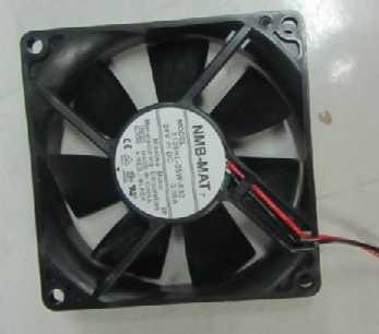
145 2 1 Page 143
TECHNICIAN MANUAL Electronic Table -Top Autoclaves Model ELARA
 TECHNICIAN MANUAL Electronic Table -Top Autoclaves Model ELARA Cat. No. MAN205-0343001EN Rev. K Tuttnauer Europe b.v., Paardeweide 36, 4824 EH, Breda, P.O. Box 7191, 4800 GD Breda, Netherlands. +31/76-5423510,
TECHNICIAN MANUAL. Pre/Post-vacuum Class B Table top Autoclave. Model ELARA 11. (CAT Controller)
") TECHNICIAN MANUAL Pre/Post-vacuum Class B Table top Autoclave Model ELARA 11 (CAT Controller) Cat. No. MAN205-0343001EN Rev. P 8-10-11 Manufactured by: Tuttnauer Co. Ltd., Har Tuv Industrial zone B P.O.Box
TECHNICIAN MANUAL Pre/Post-vacuum Class B Table top Autoclave Model ELARA 11 (CAT Controller) Cat. No. MAN205-0343001EN Rev. P 8-10-11 Manufactured by: Tuttnauer Co. Ltd., Har Tuv Industrial zone B P.O.Box
User manual. Standard Modular Chiller HP 1/8 compressors with CAREL driver Application program for pco 1, pco 2, pco 3, pco C and pco XS.
 Standard Modular Chiller HP 1/8 compressors with CAREL driver Application program for pco 1, pco 2, pco 3, pco C and pco XS. User manual Manual version: 2.4 dated 27/02/08 Program code: FLSTDmMCDE LEGGI
TECHNICIAN MANUAL. Electronic Table - top Pre and Post Vacuum Autoclaves models 2540 & 3870 EHS. Cat. No. MAN E Rev. D
 TECHNICIAN MANUAL Electronic Table - top Pre and Post Vacuum Autoclaves models 2540 & 3870 EHS Cat. No. MAN205-0063-005E Rev. D TABLE OF CONTENTS PARAGRAPH PAGE NO. 1 INTRODUCTION...4 2 SYMBOL DESCRIPTION...4
PowerView PV380-R2 Mechanical Configuration
 PowerView PV380-R2 Mechanical Configuration Operations Manual *Products covered in this document comply with European Council electromagnetic compatibility directive 2004/108/EC and electrical safety directive
OPERATING MANUAL Digital Diesel Control Remote control panel for WhisperPower generator sets
 Art. nr. 40200261 OPERATING MANUAL Digital Diesel Control Remote control panel for WhisperPower generator sets WHISPERPOWER BV Kelvinlaan 82 9207 JB Drachten Netherlands Tel.: +31-512-571550 Fax.: +31-512-571599
Combined Ventilation Controller RVWS-T-224HA
 Combined Ventilation Controller RVWS-T-224HA 8-stage Control for Power/Natural Applications 2 variable speed stages, 2 curtain winch stages, 2 fixed speed ventilation stages, 1 thermo/mister cycle stage
JConn Inv. PID Controller Instruction Manual
 JConn Inv. PID Controller Instruction Manual This information is specific to the Mypin TA4 based controller sold by JConn Inv. but it should work for most TA4 types - within limits. Table of Contents 1.
BRAKE TESTER DECELEROMETER
 OC3010_GBM_21009 BRAKE TESTER DECELEROMETER OWNER S MANUAL Version 8.++ ORBIT CONTROLS AG Zürcherstrasse 137 CH-8952 Schlieren/ZH Tel: + 41 44 730 2753 Fax: + 41 44 730 2783 info@orbitcontrols.ch www.orbitcontrols.ch
Inlet Controller TC5-ITA USER'S MANUAL. M rev. 02 K rev. 00
 Inlet Controller TC5-ITA USER'S MANUAL M 890-00047 rev. 02 K 895-00458 rev. 00 TABLE OF CONTENTS PRECAUTIONS... 3 FEATURES... 4 LOCATION OF THE CONTROLS... 5 Status Leds...5 Internal Switches...6 INSTALLATION
INSTALLER MANUAL USER MANUAL. Contents
 Installation & user manual two way Contents INSTALLER MANUAL Important information General 1. Technical data 2. Description Installation: 1. Positioning the unit 2. Connection. 3. Parts description. 4.
INSTALLATION AND OPERATION INSTRUCTION
 INSTALLATION AND OPERATION INSTRUCTION ATi Max 2-1/2-6, 65-150mm Install the ATi Max valve either in the supply or return pipework for the unit. It is recommended that a strainer be installed prior to
Application Engineering Europe
 Date of last update: Feb-12 Ref: D7.8.4/0112-0212/E Application Engineering Europe CORESENSE DIAGNOSTICS FOR STREAM REFRIGERATION COMPRESSORS 1/17 1 Introduction CoreSense is an ingredient brand name for
Supersedes CL2 (512) Form CL2 (615) STARTUP CHECKLIST PHONE: CUSTOMER ORDER NO: JCI TEL NO: JCI ORDER NO: JCI CONTRACT NO:
 Form CL2 (615) STARTUP CHECKLIST PHONE: CUSTOMER ORDER NO: JCI TEL NO: JCI ORDER NO: JCI CONTRACT NO:") YMC 2 - MOD A STARTUP CHECKLIST Supersedes 160.78-CL2 (512) Form 160.78-CL2 (615) STARTUP CHECKLIST CUSTOMER: JOB NAME: ADDRESS: LOCATION: PHONE: CUSTOMER ORDER NO: JCI TEL NO: JCI ORDER NO: JCI CONTRACT
YMC 2 - MOD A STARTUP CHECKLIST Supersedes 160.78-CL2 (512) Form 160.78-CL2 (615) STARTUP CHECKLIST CUSTOMER: JOB NAME: ADDRESS: LOCATION: PHONE: CUSTOMER ORDER NO: JCI TEL NO: JCI ORDER NO: JCI CONTRACT
USER GUIDE Digital Thermostat GUIDE D UTILISATION Thermostat digital Bedienungsanleitung Termostato digital 50-72
 BT D-01 1 2 USER GUIDE GB Digital Thermostat 4-25 GUIDE D UTILISATION F Thermostat digital 26-49 Bedienungsanleitung D Termostato digital 50-72 GUÍA DE USUARIO ES Termostato digital 74-97 GUIA DO UTILIZADOR
MAGPOWR Spyder-Plus-S1 Tension Control
 MAGPOWR TENSION CONTROL MAGPOWR Spyder-Plus-S1 Tension Control Instruction Manual Figure 1 EN MI 850A351 1 A COPYRIGHT All of the information herein is the exclusive proprietary property of Maxcess International,
VL400 Melters. Safety. Introduction. Nordson Corporation OPERATOR S CARD P/N A
 Nordson Corporation OPERATOR S CARD P/N 052644A VL400 Melters Safety WARNING: Allow only qualified personnel to perform the following tasks. Follow the safety instructions in this document and all other
HGM1780. Automatic Genset Controller USER MANUAL. Smartgen Technology
 HGM1780 Automatic Genset Controller USER MANUAL Smartgen Technology Smartgen Technology Co., Ltd No. 28 Jinsuo Road Zhengzhou Henan Province P. R. China Tel: 0086-371-67988888/67981888 0086-371-67991553/67992951
Vission 20/20 micro-controller. Operation and service manual
 Vission 20/20 micro-controller Operation and service manual Section Title Table of Contents Section Number How To Use This Manual...TOC-8 Section 1 Operational Flow Charts Requirements to Start Compressor...1-1
CORESENSE DIAGNOSTICS FOR STREAM REFRIGERATION COMPRESSORS
 Date of last update: Apr-15 Ref: D7.8.4/0112-0415/E Application Engineering Europe CORESENSE DIAGNOSTICS FOR STREAM REFRIGERATION COMPRESSORS CoreSense Diagnostics for Stream Refrigeration Compressors...
Temperature Controller OVATION 214 User's Guide
 Temperature Controller User's Guide Read this guide carefully before using the controller. 890-00045 rev.00 TABLE OF CONTENTS Page TABLE OF CONTENTS... 2 PRECAUTIONS... 3 FEATURES... 4 LOCATION OF THE
348002K/348012K Manifold Block Style Service Manual 12/2000
 348002K/348012K Manifold Block Style Service Manual 12/2000 Service Manual 348002K/348012K Manifold Block Style Recovery/Recycling/Recharging Unit For R-12 or R-134a Only TABLE OF CONTENTS: Theory of Operation
SmartPak Welding Controller WK-MPS-16 Constant Current
 SmartPak Welding Controller WK-MPS-16 Constant Current Features Latest state of the art ATMEL 8 bit microprocessor technology Synchronous digital welding control allows absolute precision Up to16 programmers
Vission 20/20 micro-controller. Operation and service manual Version 2.6
 Vission 20/20 micro-controller Operation and service manual Version 2.6 Important Message READ CAREFULLY BEFORE OPERATING YOUR COMPRESSOR. The following instructions have been prepared to assist in operation
ECL Apex 10. User Guide. ECL Apex 10 *087R9745* Installation and configuration. *vijem102*
 User Guide ECL Apex 10 *087R9745* *vijem102* Installation and configuration VI.JE.M1.02 Danfoss 11/2004 DH-SMT VI.JE.M1.02 Danfoss 11/2004 DH-SMT ECL Apex 10 VI.JE.M1.02 Danfoss 11/2004 DH-SMT VI.JE.M1.02
GENERAL INFORMATION MECHANICAL INSTALLATION PRESSURE INDEPENDENT VALVES 2-1/2"-10" MVP INSTALLATION & OPERATION INSTRUCTIONS UNION CONNECTIONS
 GENERAL INFORMATION INSTALLATION & OPERATION INSTRUCTIONS 1. Clean the lines upstream of valve particles larger than 1/16" diameter (welding slag, pipe scale and other contaminants). Griswold Controls
! WARNING To avoid risk of electrical shock, personal injury or death; disconnect power to oven before servicing, unless testing requires power.
 Technical Information Electric Slide-In Range JES9750AAB/S/W JES9800AAB/Q/S/W JES9860AAB/S/W Due to possibility of personal injury or property damage, always contact an authorized technician for servicing
SERVICE MANUAL (DOMESTIC & INTERNATIONAL)
") SERVICE MANUAL (DOMESTIC & INTERNATIONAL) DUAL TECHNOLOGY FINISHER MODEL 1960 & 1980 SERIES Lincoln Foodservice Products, LLC 1111 North Hadley Road Fort Wayne, Indiana 46804 United States of America Telephone:
SERVICE MANUAL (DOMESTIC & INTERNATIONAL) DUAL TECHNOLOGY FINISHER MODEL 1960 & 1980 SERIES Lincoln Foodservice Products, LLC 1111 North Hadley Road Fort Wayne, Indiana 46804 United States of America Telephone:
User Manual Solar Charge Controller 3KW
 User Manual Solar Charge Controller 3KW Version: 1.3 CONTENTS 1 ABOUT THIS MANUAL... 1 1.1 Purpose... 1 1.2 Scope... 1 1.3 SAFETY INSTRUCTIONS... 1 2 INTRODUCTION... 2 2.1 Features... 2 2.2 Product Overview...
Automatic Genset Controller, AGC-4 Display readings Push-button functions Alarm handling Log list
 OPERATOR'S MANUAL Automatic Genset Controller, AGC-4 Display readings Push-button functions handling Log list DEIF A/S Frisenborgvej 33 DK-7800 Skive Tel.: +45 9614 9614 Fax: +45 9614 9615 info@deif.com
Installation Instructions & Users Manual
 Installation Instructions & Users Manual UTILITY/ BUILDING INPUT 120 VAC ( OPTION) 15-20A N L CONTROL BOARD G SECURITY LIGHTING POWER SUPPLY (OPTION) CHARGER- POWER SUPPLY ASSBY XFMR (OPTION) CBM MODEL
INSTALLATION GUIDE Table of Contents
 CT-3100 Automatic transmission remote engine starter systems. What s included..2 INSTALLATION GUIDE Table of Contents Door lock toggle mode..... 4 Notice...2 Installation points to remember. 2 Features..2
TIMER INTERFACE USER MANUAL
 TIMER INTERFACE USER MANUAL Premium Efficiency Two-Speed Motor with Integrated Timer Formerly A. O. Smith Electrical Products Company A Regal Beloit Company COPYRIGHT Copyright 2011, Regal Beloit EPC,
Factory Packaged Controls. OE (AAON Part No. V12090) MODGAS-X Controller Field Technical Guide
 MODGAS-X Controller Field Technical Guide") Factory Packaged Controls OE377-26-00058 (AAON Part No. V12090) MODGAS-X Controller Table of Contents GENERAL INFORMATION... 3 Overview...3 Features...3 INSTALLATION & WIRING... 4 Supply Air Temperature
Factory Packaged Controls OE377-26-00058 (AAON Part No. V12090) MODGAS-X Controller Table of Contents GENERAL INFORMATION... 3 Overview...3 Features...3 INSTALLATION & WIRING... 4 Supply Air Temperature
REV F2.0. User's Manual. Hydraulic ABS (HABS) Hydraulic Power Brake (HPB) Page 1 of 28
 Hydraulic Power Brake (HPB) Page 1 of 28") REV F2.0 User's Manual Hydraulic ABS (HABS) Hydraulic Power Brake (HPB) Page 1 of 28 Table of Contents INTRODUCTION...4 Starting TOOLBOX Software... 5 MAIN MENU...6 System Setup... 6 Language... 7 Select
REV F2.0 User's Manual Hydraulic ABS (HABS) Hydraulic Power Brake (HPB) Page 1 of 28 Table of Contents INTRODUCTION...4 Starting TOOLBOX Software... 5 MAIN MENU...6 System Setup... 6 Language... 7 Select
PF3100 TROUBLESHOOTING SOLUTIONS TO COMMON PROBLEMS. v1.1 Revised Nov 29, 2016
 PF3100 TROUBLESHOOTING SOLUTIONS TO COMMON PROBLEMS v1.1 Revised Table of Contents 1 Common Alarms and Warnings... 1 2 Common Issues... 6 2.1 Communication problems... 6 2.1.1 Controller communication
Inlet Controller SB3500 USER'S MANUAL
 Inlet Controller USER'S MANUAL NOTICE Every effort has been made to ensure that this manual is complete, accurate and up-to-date. The information contained in it is however subject to change without notice
SNMP dedicated to ORVALDI Solar Infini
 SNMP dedicated to ORVALDI Solar Infini User s Manual Management Software for Solar Inverter Table of Contents 1. 2. 3. Overview...1 1.1 Introduction...1 1.2 Features...1 1.3 Overlook...1 1.4 Installation
UltraClave Automatic Sterilizers
 UltraClave Automatic Sterilizers Model Numbers: M9 M9D M11 M11D -020 thru -022-020 & -022-020 thru -022-020 & -022 Serial Number Prefixes: RN, RP, RR, V RW, RX, V RS, RT, RV, V RY, RZ, V Service and Parts
MODEL 520 REMOTE START ENGINE MANAGEMENT SYSTEM
 MODEL 520 REMOTE START ENGINE MANAGEMENT SYSTEM DSE 520 ISSUE 4 4/4/02 MR 1 TABLE OF CONTENTS Section Page INTRODUCTION... 4 CLARIFICATION OF NOTATION USED WITHIN THIS PUBLICATION.... 4 1. OPERATION...
Documentation. RM-BV4 Micro DP. Filter control
 Documentation RM-BV4 Micro DP Filter control Contents 1 Safety instructions... 3 2 Device description... 3 3 Installation... 4 4 Installation... 5 4.1 Connection of the differential pressure measuring
ECONOMISER SERIES E2T USER MANUAL
 TURBO S.R.L. Electronic Control Systems for Dust Collectors e-mail: info@turbocontrols.it web: www.turbocontrols.it TEL. ++39 (0)362 574024 FAX ++39 (0)362 574092 ECONOMISER SERIES E2T USER MANUAL 24/06/2014
Digital Diesel Control Remote control panel for GENVERTER GV4 and GV7i
 OPERATING MANUAL Digital Diesel Control Remote control panel for GENVERTER GV4 and GV7i Art. nr. 40200801 WHISPER POWER BV ENGLISH: PAGE 1 Kelvinlaan 82 9207 JB Drachten NEDERLANDS: PAGINA 41 Netherlands
Advanced User Manual
 Advanced User Manual Banks SpeedBrake For use with Palm Tungsten E2 2004-2005 Chevy/GMC 6.6L (LLY) Turbo-Diesel Pickup THIS MANUAL IS FOR USE WITH KITS 55419 & 55421 Gale Banks Engineering 546 Duggan Avenue
EXCELSIOR-HENDERSON MOTORCYCLE MANUFACTURING COMPANY 805 HANLON DRIVE BELLE PLAINE, MINNESOTA TELE: /FAX:
 All text, photographs, and illustrations in this handbook are based on the most current product information available at the time of publication. Product improvements or other changes may result in differences
OPERATION. MAINTENANCE MANUAL Pre-vacuum Steam Heated Autoclave with One Manual Hinged Door
 OPERATION & MAINTENANCE MANUAL Pre-vacuum Steam Heated Autoclave with One Manual Hinged Door Model 5596 SP-1R ND S.N.: 2912082 Cat. No. MAN205-0076072EN Rev A May 2010 Manufactured by: Tuttnauer Co. Ltd.,
Installation, Operation, and Maintenance Manual CEMLINE CORPORATION
 $5.00 Installation, Operation, and Maintenance Manual CEMLINE CORPORATION CEM-TROL II Solid State Control Module and Electronic Control Valves P. O. Box 55, Cheswick, PA, 15024 Phone: (724) 274-5430 FAX
BIGLA30-T/BIELA14-T Event Codes Quick Reference EXPLANATION CORRECTIVE ACTION PARTS TO CARRY ON SERVICE CALL
 E13 TEMPERATURE PROBE FAILURE E16 HIGH LIMIT 1 EXCEEDED A. TEMP Probe reading out of range. B. Bad Connection. C. Problem with the temperatur e measuring circuitry including the probe. High limit temperature
L5000Plus. Programming Guide
 Page 1 of 34 JDE1955 IssB s6 July 2009 Contents Safety.. 3 L5000Plus Programmer Keys 4 Passwords.. 4 L5000Plus Programming Access Levels 4 Operator Level Access 4 Technician Level Access 8 Programmer Level
CEMLINE CORPORATION P. O. BOX 55 CHESWICK, PENNSYLVANIA Phone: (724) FAX (724)
 FAX (724)") Installation, Operation, and Maintenance Manual CEMLINE CORPORATION Electronic Controls for Water Heaters with RWD45U Controller CEMLINE CORPORATION P. O. BOX 55 CHESWICK, PENNSYLVANIA 15024 Phone: (724)
Installation, Operation, and Maintenance Manual CEMLINE CORPORATION Electronic Controls for Water Heaters with RWD45U Controller CEMLINE CORPORATION P. O. BOX 55 CHESWICK, PENNSYLVANIA 15024 Phone: (724)
! WARNING To avoid risk of electrical shock, personal injury or death; disconnect power to oven before servicing, unless testing requires power.
 Technical Information Gas Slide-In Range JGS8750ADB/S/W JGS8850ADB/Q/S/W Due to possibility of personal injury or property damage, always contact an authorized technician for servicing or repair of this
Section 55 Chapter 6
 Section 55 Chapter 6 REMOTE HYDRAULICS CONTROLLER Calibration and Fault Codes 6-12880NH TABLE OF CONTENTS REMOTE HYDRAULICS CONTROLLER CALIBRATION... 55-5 Requirements For Calibration... 55-5 Aux Set Main
Intelli-Feed Controller User s Manual Intelli-Feed Digital Tachometer and Hourmeter
 Intelli-Feed Controller User s Manual Intelli-Feed Digital Tachometer and Hourmeter Part #: 9047 Table of Contents: Table of Contents 2 Intelli-Feed TM User Interface 3 Equipment Diagnostic Indicators
Temperature Controller. TC5+2V4SA Plus USER'S MANUAL
 Temperature Controller TC5+2V4SA Plus USER'S MANUAL NOTICE Every effort has been made to ensure that this manual is complete, accurate and up-to-date. The information contained in it is however subject
R & D SPECIALTIES ROTROL I USER'S MANUAL
 R & D SPECIALTIES ROTROL I USER'S MANUAL TABLE OF CONTENTS INTRODUCTION...2 SPECIFICATIONS...2 CONTROLS AND INDICATORS...3 TIME DELAYS...4 INSTALLATION...5 SYSTEM OPERATION...9 TROUBLESHOOTING...13 OPTIONAL
Instructions For Use VATEA. Endodontic Irrigation Device
 Instructions For Use VATEA Endodontic Irrigation Device VATEA Irrigation System Instructions for use 1. Indications for use The VATEA system is intended to be attached to dental handpieces to deliver irrigation
Application Engineering
 Application Engineering February, 2009 Copeland Digital Compressor Controller Introduction The Digital Compressor Controller is the electronics interface between the Copeland Scroll Digital Compressor
GRUNDFOS INSTRUCTIONS. Control HVAC. Installation and operating instructions. Other languages. net.grundfos.com/qr/i/
 GRUNDFOS INSTRUCTIONS Control HVAC Installation and operating instructions Other languages net.grundfos.com/qr/i/98800750 English (GB) English (GB) Installation and operating instructions Original installation
CURTIS TOLEDO. AF Series Compressors VS models with VFD WARNING
 AUGUST, 2004 REV.A CURTIS TOLEDO OPERATOR S MANUAL SUPPLEMENT AF Series Compressors VS models with VFD WARNING Personal injury and/or equipment damage will result by failing to pay attention to the vital
EXPERT 2V4SA. Temperature Controller. User s manual CLEAN MODE COMPENSATION HUMIDITY OUTSIDE TEMPERATURE
 CLEAN MODE Temperature Controller User s manual CURRENT CONDITIONS ROOM TEMPERATURE PROBE TEMPERATURE OUTSIDE TEMPERATURE RELATIVE HUMIDITY STATIC PRESSURE TIME / DATE SETTINGS SET POINT / CURVE MINIMUM
Off Grid Solar Inverter. LVS 50M User Manual
 Off Grid Solar Inverter LVS 50M User Manual Save This Manual Please read this manual carefully prior to installation, wiring, operation and maintenance of the LVS M Series. This manual contains important
Installation. Part A, Section 3. This section covers the following unit configurations. 3400V 3500V. Voltage 4. Pump Piston (E, F, G)
") Part A, Section 3 Model This section covers the following unit configurations. Voltage 4 300V 3400V 3500V Pump Piston (E, F, G) Manifold Control 4-Port (A) 6-Port (B or C) -Port (S or T) Vista Pattern
Part A, Section 3 Model This section covers the following unit configurations. Voltage 4 300V 3400V 3500V Pump Piston (E, F, G) Manifold Control 4-Port (A) 6-Port (B or C) -Port (S or T) Vista Pattern
Installation and Maintenance Instructions. World Leader in Modular Torque Limiters. PTM-4 Load Monitor
 World Leader in Modular Torque Limiters Installation and Maintenance Instructions PTM-4 Load Monitor 1304 Twin Oaks Street Wichita Falls, Texas 76302 (940) 723-7800 Fax: (940) 723-7888 E-mail: sales@brunelcorp.com
SAFETY PRECAUTIONS Warning: Read and understand all instructions in this manual. Use appropriate personal safety equipment including hearing and eye p
 SAFETY PRECAUTIONS Warning: Read and understand all instructions in this manual. Use appropriate personal safety equipment including hearing and eye protections when using the scanner in or near the vehicle
OPERATING AND MAINTENANCE MANUAL. Primary Current Injection Test Set. 750ADM-H mk2
 OPERATING AND MAINTENANCE MANUAL Product: Type: Primary Current Injection Test Set 750ADM mk2 750ADM-H mk2 DESIGNED AND MANUFACTURED BY: T & R Test Equipment Limited 15-16 Woodbridge Meadows, Guildford,
BTB TYPE AUTOMATIC TRANSFER SWITCH (ATS)
") BTB TYPE AUTOMATIC TRANSFER SWITCH (ATS) Programmable Automatic Transfer Switch Operation Manual Main Switch Rated Current 2P/3P/4P 250Amp 2P 400 Amp Main Switch Rated Voltage 690 Vac Taiwan Patent Number
BTB TYPE AUTOMATIC TRANSFER SWITCH (ATS) Programmable Automatic Transfer Switch Operation Manual Main Switch Rated Current 2P/3P/4P 250Amp 2P 400 Amp Main Switch Rated Voltage 690 Vac Taiwan Patent Number
Te 803 Electronic Controller. Service, Operation & Technical Information Manual
 Te 803 Electronic Controller Service, Operation & Technical Information Manual WARNING! Technical descriptions and data given in this document are accurate, to the best of our knowledge, but can be subject
Installation. Part A, Section 3. This section covers the following unit configurations. Voltage 1, 2, 3. Vista Standard (V) A3EN-04-[3V-A-AAXV]-11
![Installation. Part A, Section 3. This section covers the following unit configurations. Voltage 1, 2, 3. Vista Standard (V) A3EN-04-[3V-A-AAXV]-11](/thumbs/87/95082297.jpg "Installation. Part A, Section 3. This section covers the following unit configurations. Voltage 1, 2, 3. Vista Standard (V) A3EN-04-[3V-A-AAXV]-11") Part A, Section 3 This section covers the following unit configurations. Model All Voltage 1, 2, 3 Pump All Manifold All Control Vista Standard (V) A 3-0 A 3-1 Section A 3 WARNING: Allow only qualified
Part A, Section 3 This section covers the following unit configurations. Model All Voltage 1, 2, 3 Pump All Manifold All Control Vista Standard (V) A 3-0 A 3-1 Section A 3 WARNING: Allow only qualified
DIESEL Engine Fire Pump Controllers Features
 1-1 Printer / Recorder The industrial grade thermal printer is housed in a rugged steel enclosure within the controller. The on/off switch, feed and reset buttons are front accessible. A bi-color status
MATRIX LLC LEVEL CONTROL PANEL
 MATRIX LLC LEVEL CONTROL PANEL Installation Operation Maintenance Manual 1-26-09 REV-0.3 1 INDEX Introduction. 3 Product Configurations..... 4 I/O Descriptions. 8 Operation o Intercooler, Accumulator,
Quick Setup Guide for IntelliAg Model YP Air Pro
 STEP 1: Pre-Programming Preparation: The Quick Guide assumes the Virtual Terminal, Master Switch, Working Set Master, Working Set Member, and all sensors have been connected and properly installed. Reference
HP21 SERVICE SUPPLEMENT UNIT INFORMATION. TSC6 Two-Speed Control
 SERVICE UNIT INFORMATION SUPPLEMENT HP21 Corp. 9426 L10 Litho U.S.A. All HP21-4 and -5 units (single and three phase) are equipped with a TSC6 two-speed control. The TSC6 (A14) two-speed control contains
TECHNICIAN MANUAL. Electronic Table -Top Autoclaves models EZ9, EZ10, EZ10K
 TECHNICIAN MANUAL Electronic Table -Top Autoclaves models EZ9, EZ10, EZ10K Cat. No. MAN205-0275001EN Rev. E Tuttnauer Europe b.v., Paardeweide 36, 4824 EH, Breda, P.O. Box 7191, 4800 GD Breda, Netherlands.
BERMAD Waterworks. Insertion Flow Meter Device (IFM)
") IFM-MUT1222PRV BERMAD's IFM-MUT1222-PRV SENSOR is designed for measuring the flow rate of valves sized DN80 to DN600 (3-24 ). This document describes the installation process of the sensor. For larger
IFM-MUT1222PRV BERMAD's IFM-MUT1222-PRV SENSOR is designed for measuring the flow rate of valves sized DN80 to DN600 (3-24 ). This document describes the installation process of the sensor. For larger
OS3050 OS3051. Controller for reverse osmosis plants. Instruction manual. Softwareversion 3.04
 OS3050 OS3051 Controller for reverse osmosis plants Instruction manual Softwareversion 3.04 Contents Overview... 1 "PRODUCTION" mode... 1 "STANDBY" mode... 2 "RINSE" Mode... 2 "MAINTENANCE" Mode... 3 "STANDBY
Quick Setup Guide for IntelliAg Model YP40 20 Air Pro
 STEP 1: Pre-Programming Preparation: The Quick Guide assumes the Virtual Terminal, Master Switch, Working Set Master, Working Set Member, and all sensors have been connected and properly installed. Reference
SECTION B: SYSTEM OPERATING COMPONENTS
 SECTION B: SYSTEM OPERATING COMPONENTS A brief description of the machine, Cable Processor Module and tooling will provide a better understanding of the various functions of the IMA system. SECTION B1:
PCT-3001 plus. Display LCD
 PCT3 plus DIGITAL PRESSURE CONTROLLER FOR COOLING PLANTS DESCRIPTION Pressure controller for refrigeration systems capable to control suction (compressors) and discharge (fans) pressures. It is possible
Maximiser Progressive Controller
 Maximiser Progressive Controller Street & Race Model Owner's Manual 44 (0) 01302 834343 www.noswizard.com Introduction Congratulations on purchasing the Maximiser for the ultimate in progressive nitrous
MC200CAB/4 Integral Version
 Issue 2.2 Mar 2017 MC200CAB/4 Integral Version Industrial & Commercial Heating Systems. www.powrmatic.co.uk Setting Instructions WARNING: THIS APPLIANCE MUST BE EARTHED IMPORTANT: Reset from Lockout is
Senior Swing Control Box. Table of Contents
 *740100* 740100 2800 Overhead Consealed Series 9500 Surface Applied Series Senior Swing Control Box Installation Instructions important These instructions are presented in step-by-step sequence. It is
TECHNICIAN MANUAL. Electronic Table -Top Autoclaves models 1730, 2340, 2540, 3140, 3850, 3870 E, EK, EA & EKA
 TECHNICIAN MANUAL Electronic Table -Top Autoclaves models 1730, 2340, 2540, 3140, 3850, 3870 E, EK, EA & EKA Cat. No. MAN205-0176-000E Rev. E Tuttnauer Europe b.v., Paardeweide 36, 4824 EH, Breda, P.O.
Rally computer 3 Rally computer 3.GPS *
 Rally computer 3 Rally computer 3.GPS * User manual. Installation and configuration instructions. (with links to video instructions online at : www.rallycomputer.com ) * Content marked applies only to
Be2K-Plus AMF panel control wiring --
 Be2K-Plus OEM's Manual V200 - August - 014 page 1 Be2K-Plus AMF panel control wiring -- Consult Section 17.0 for software upgrades & revisions The information in this document may be subject to change
Wallbox Commander. User Guide WBCM-UG-002-EN 1/11
 Wallbox Commander User Guide 1/11 Welcome to Wallbox Congratulations on your purchase of the revolutionary electric vehicle charging system designed with cuttingedge technology to satisfy your daily needs.
WP37 & HT37 User Manual
 WP37 & HT37 User Manual Origio WP37 & HT37 Warming Plates & Heated Trolley Warming Plates WP37 300 WP37 500 Heated Trolley HT37 Origio WP37 Component Description Heated work surface Model WP37 300 Power
B-RAD Select USER MANUAL TABLE OF CONTENTS
 TABLE OF CONTENTS TABLE OF CONTENTS... 1 MANUAL REVISION HISTORY... 2 IMPORTANT SAFETY NOTICE... 3 1.0 General Information... 5 1.1 System Components... 5 1.2 Specifications... 5 1.2.1 Torque Ranges...
SentryGOLD Compact. for Bennett Electronic Dispenser INSTALLATION MANUAL. Fuel Management System
 Fuel Management System SentryGOLD Compact for Bennett Electronic Dispenser INSTALLATION MANUAL 2901 Crescent Drive Tallahassee, FL 32301 (850) 878-4585 office (850) 656-8265 fax www.trakeng.com support@trakeng.com
ECLIPSE Laundry Dispenser Controller
 ECLIPSE Laundry Dispenser Controller Reference Manual Programming and Operation Online and downloadable Product Manuals and Quick Start Guides are available at www.hydrosystemsco.com Please check online
Overview. References TEST SPECIFICATION FORT WORTH, TEXAS TROTTER CONTROLS REPORT X TS-0005 A MODEL ORDER TITLE BY CHK D. Tests
 Rev A, 5/26/2009 1 26 Overview This document describes the use of the Maintenance System. This test is a built in diagnostic feature of the GEN II System and provides maintenance personnel with a diagnostic
Installation, Operation, and Maintenance Manual CEMLINE CORPORATION
 $5.00 Installation, Operation, and Maintenance Manual CEMLINE CORPORATION CEM-TROL Solid State Control Module and Electronic Control Valves P. O. Box 55, Cheswick, PA, 15024 Phone: (724) 274-5430 FAX (724)
SB 2000 PUSH TO SEARCH NEXT STAG E. Aerotech, Inc. FORM: QM 1320
 Inlet Controller SB 2000 USER'S MANUAL AUTO OPEN MANUAL PUSH TO SEARCH NEXT STAG E CLOSE Aerotech, Inc. FORM: QM 1320 4215 Legion Dr. Mason, MI 48854-1036 USA Rev. 3, Sept. 1997 Ph. (517) 676-7070 Fax
AQUATIC INTELLIGENCE FILTER CONTROL GUIDE
 AQUATIC INTELLIGENCE FILTER CONTROL GUIDE Installation and Operations AQUATIC INTELLIGENCE FILTER CONTROL SYSTEM This instruction guide of the Aquatic Intelligence Filter Control System (AIF) is intended
OPERATING INSTRUCTIONS ECON-M
 OPERATING INSTRUCTIONS ECON-M INDEX 1.0 Introduction 2.0 Salient features, Protection & Supervision 3.0 Display/ Front Panel 4.0 Switches Description 5.0 LED Annunciations Description 6.0 Lamp Test 7.0
PROFIRE 1100i IGNITION FLAME SAFETY CONTROLLER
 PROFIRE 1100i IGNITION FLAME SAFETY CONTROLLER Cautions WARNING: EXPLOSION HAZARD- -DO NOT SERVICE UNLESS AREA IS KNOWN TO BE NON- HAZARDOUS -DO NOT OPEN WHEN ENERGIZED EXPLOSION HAZARD- -SUBSTITUTION
Fan Coil Thermostat. Specification & Installation instructions TFC54F3X1. Technical Data
 Fan Coil Thermostat Feature: Selectable analog & digital output Selectable fan speed contact Selectable Fahrenheit or Celsius scale Manual Night Set Back override (programmable) Multi level lockable access
TECHNICAL MANUAL FOR ELECTRONIC SPEEDOMETER STR-RIEJU MATRIX 2
 FOR ELECTRONIC SPEEDOMETER STR-RIEJU MATRIX 2 Rel. 4.0 3.0 2.0 1.0 0.0 Release Disposal Aim Modifications on chapter 8 and 13 Deleted automatic and manual test procedure General modifications Added par.
MiG2 TIME SWITCHES. 1, 2 & 4 Channel, 365 Day, Energy Saving Time Switches
 MiG2 TIME SWITCHES 1, 2 & 4 Channel, 365 Day, Energy Saving Time Switches The MiG2 series of timers are programmable 365-day time-switches, incorporating: Multiple switching times per day Single and block
5000TOC Sensor Service Manual
 Part No. 84449 5000TOC Sensor Service Manual This document contains proprietary information, which is protected by copyright. All rights are reserved. No part of this document may be photocopied (other