Vission 20/20 micro-controller. Operation and service manual
|
|
|
- Daniel Jackson
- 6 years ago
- Views:
Transcription


1 Vission 20/20 micro-controller Operation and service manual
2
3 Section Title Table of Contents Section Number How To Use This Manual...TOC-8 Section 1 Operational Flow Charts Requirements to Start Compressor Critical Compressor Run Logic at Compressor Start Compressor Amperage Load Limiting Figure 1-1. Operational Flow Charts High Discharge Pressure Load Limiting Suction Pressure Override Load Limit During Temperature Control Section 2 Installation Recommendations Proper Wiring Sizing Voltage Source Figure 2-1. Vission 20/20 with Individual Transformer Figure 2-2. EMI and Vission 20/ Grounding Mixing Voltages DC signals Figure 2-3. Ground Wiring Figure 2-4. Mixed Voltage Wiring Wiring Methods Figure 2-5. Correct Transformer Wiring Method Figure 2-6. Incorrect Transformer Wiring Method Best Practices Section 3 Hardware Architecture Overview Figure 3-1. Hardware Architecture Overview Digital Input/Output (I/O) Table 3-1. Digital I/O Analog Inputs Table 3-2. Analog Inputs Analog Outputs Digital & Analog I/O Boards Layout Table 3-3. Analog Outputs Figure 3-2. Digital I/O Board Layout Digital Outpout Boards Figure 3-3. Digital Output Board Layout Digital Input Boards Figure 3-4. Digital Input Board Layout Digital In-Out Boards Figure 3-5. Digital Input-Output Board Layout Analog Input Boards Figure 3-6. Analog Input Board Layout Analog Input Jumper Tables Table 3-4. Analog Input Jumper Tables Analog Output Boards Figure 3-6. Analog Output Board Layout Vission 20/20 Operation and Service Manual Vilter/Emerson 35391SC TOC - 1
4 TOC - 2 Section Title Table of Contents Section Number Section 4 Main Screen Overview Figure 4-1. Digital I/O Board Layout Top Status Bar Figure 4-2. Top Status Bar Parameter Bar Figure 4-3. Parameter Bar Figure 4-4. Unit Start Pop-Up Window Bottom Status Bar Figure 4-5. Bottom Status Bar Splash Screen Figure 4-6. Splash Screen Section 5 Menu Screen Overview Navigation Buttons Figure 5-1. Menu Screen Section 6 Compressor Control Overview Pulse Proportional Control Figure 6-1. Compressor Control Screen Auto-Cycle Figure 6-2. Proportional Band & Setpoint Variable Frequency Drive (VFD) Figure 6-3. VFD One-Step Control Method Figure 6-4. VFD Two-Step Control Method Pumpdown Control Pulldown Control Control Mode Stop load & Force unload Capacity Slide Triggered Outputs Volume Slide Position Offset Soft Load Load Anticipating Oil Control Liquid Injection Section 7 Alarms and Trips Overview Alarms and Trips Setpoints Figure 7-1. Alarms and Trips Screen Compressor Inhibits Safety Failure Messages Section 8 Timers Overview Timer Setpoints Figure 8-1. Timers Screen Section 9 Compressor Scheduling Overview Scheduling Setpoint Figure 9-1. Compressor Scheduling Screen Vission 20/20 Operation and Service Manual Vilter/Emerson 35391SC
5 Section Title Table of Contents Section Number Section 10 Compressor Sequencing Overview Pressure Control Setpoints Figure Compressor Sequencing Screen Section 11 Condenser Control Overview Condenser Control Setpoint Figure Condenser Control Screen Step Control Figure Step Control Screen VFD Settings Section 12 Service Options Overview Digital Outputs Figure Service Options Screen Analog Outputs Section 13 Instruments Calibration Overview Pressure and Temperature Inputs Figure Instruments Calibration Screen Motor Current Remote Capacity Analog Inputs Section 14 Slide Calibration Overview Capacity Slide Valve Potentiometer Figure Slide Calibration Screen Volume Slide Valve Potentiometer Slide Valve Operation Slide Valve Actuator Calibration for Optical Style Motors Figure Photochopper Command Shaft Rotation Table Command Shaft Rotation Required By Actuator Slide Valve Troubleshooting Guide Table Slide Valve Troubleshooting Guide Slide Valve Actuator Troubleshooting Guide Blink Code Table LED Blink Codes and Troubleshooting Guide Section 15 Trend Chart Overview Chart Operation Figure Trend Chart Screen Trend Data Storage Setup Figure Trend Setup Screen Vission 20/20 Operation and Service Manual Vilter/Emerson 35391SC TOC - 3
6 Section Title Table of Contents Section Number Section 16 Event List Overview Event list Columns Figure Event List Screen Section 17 Input / Output Overview Figure Input/Output Screen Section 18 Auxiliary Input / Output Overview Digital Inputs Figure Auxiliary Input/Output Screen Digital Outputs Analog Inputs Analog Outputs Control Section 19 Configuration Overview Units Time & Date Figure Configuration Screen - Page Communications Touchscreen Anti-Recycle Restart On Power Failure Compressor Sequencing Language Model & Refrigerant Figure Configuration Screen - Page Compressor Control Optional Function Selection Condenser Control Oil Pump Oil Cooling Motor Current Device Figure Configuration Screen - Page Digital Inputs Analog Inputs Figure Configuration Screen - Page Figure Configuration Screen - Page Analog Outputs Digital Outputs I/O Configuration Figure Configuration Screen - Page TOC - 4 Vission 20/20 Operation and Service Manual Vilter/Emerson 35391SC
7 Section Title Table of Contents Section Number Section 20 Data Backup Overview Save / Load Figure Data Backup Screen - Save/Load Migrate Factory Reset Figure Data Backup Screen - Migrate and Factory Reset Section 21 Maintenance Overview Checklist Figure Maintenance Screen Notes Log Chart Section 22 User Access Overview Apply Figure User Access Screen - Login Figure User Access Screen - Manage Accounts Login Manage Accounts Screen Security Levels Table Security Access Levels Section 23 Help Screen Overview Screen Features: Figure Help Screen Figure Version Pop-Up Screen Section 24 Twin Screw Control Overview Setup Figure Twin Screw Control Screen Operation Section 25 Cool Compression Control Overview Setup Figure Cool Compression Control Screen Figure Cool Compression Control Functions Screen Control Functions Operational Differences from Single Screw Vission 20/20 Operation and Service Manual Vilter/Emerson 35391SC TOC - 5
8 List of Tables and Figures Table/Figure Page Number Table 3-1. Digital I/O Table 3-2. Analog Inputs Table 3-3. Analog Outputs Table 3-4. Analog Input Jumper Tables Table Command Shaft Rotation Required By Actuator Table Slide Valve Troubleshooting Guide Table LED Blink Codes and Troubleshooting Guide Table Security Access Levels Figure 1-1. Operational Flow Charts Figure 2-1. Vission 20/20 with Individual Transformer Figure 2-2. EMI and Vission 20/ Figure 2-3. Ground Wiring Figure 2-4. Mixed Voltage Wiring Figure 2-5. Correct Transformer Wiring Method Figure 2-6. Incorrect Transformer Wiring Method Figure 3-1. Hardware Architecture Overview Figure 3-2. Digital I/O Board Layout Figure 3-3. Digital Output Board Layout Figure 3-4. Digital Input Board Layout Figure 3-5. Digital Input-Output Board Layout Figure 3-6. Analog Input Board Layout Figure 3-7. Analog Output Board Layout Figure 4-1. Digital I/O Board Layout Figure 4-2. Top Status Bar Figure 4-3. Parameter Bar Figure 4-4. Unit Start Pop-Up Window Figure 4-5. Bottom Status Bar Figure 4-6. Splash Screen Figure 5-1. Menu Screen Figure 6-1. Compressor Control Screen Figure 6-2. Proportional Band & Setpoint Figure 6-3. VFD One-Step Control Method Figure 6-4. VFD Two-Step Control Method Figure 7-1. Alarms and Trips Screen Figure 8-1. Timers Screen Figure 9-1. Compressor Scheduling Screen Figure Compressor Sequencing Screen Figure Condenser Control Screen Figure Step Control Screen Figure Service Options Screen Figure Instruments Calibration Screen Figure Slide Calibration Screen Figure Photochopper Figure Trend Chart Screen Figure Trend Setup Screen Figure Event List Screen Figure Input/Output Screen Figure Auxiliary Input/Output Screen Figure Configuration Screen - Page Figure Configuration Screen - Page Figure Configuration Screen - Page TOC - 6 Vission 20/20 Operation and Service Manual Vilter/Emerson 35391SC
9 Table/Figure List of Tables and Figures Page Number Figure Configuration Screen - Page Figure Configuration Screen - Page Figure Configuration Screen - Page Figure Data Backup Screen - Save/Load Figure Data Backup Screen - Migrate and Factory Reset Figure Maintenance Screen Figure User Access Screen - Login Figure User Access Screen - Manage Accounts Figure Help Screen Figure Version Pop-Up Screen Figure Twin Screw Control Screen Figure Cool Compression Control Screen Figure Cool Compression Control Functions Screen END OF TOC Vission 20/20 Operation and Service Manual Vilter/Emerson 35391SC TOC - 7
10 How to Use This Manual This manual contains instructions for the Vission 20/20 Operation & Service Manual. It has been divided into 25 sections. CAUTION - Caution statements are shown when there are potentially hazardous situations, if not avoided, will result in damage to equipment. Section 1: Operational Flow Charts Section 2: Installation Recommendations Section 3: Hardware Architecture Section 4: Main Screen Section 5: Menu Screen Section 6: Compressor Control Section 7: Alarms & Trips Section 8: Timers Section 9: Compressor Scheduling Section 10: Compressor Sequencing Section 11: Condensor Control Section 12: Service Options Section 13: Instruments Calibration Section 14: Slide Calibration Section 15: Trend Chart Section 16: Event List Section 17: Input/Output Section 18: Auxiliary Input/Output Section 19: Configuration Section 20: Data Backup Section 21: Maintenance Section 22: User Access Section 23: Help Screen Section 24: Twin Screw Control Section 25: Cool Compression Control NOTE - Notes are shown when there are addtional information pertaining to the instructions explained. NOTICE - Notices are shown when there are important information that can help avoid system failure. For additional information pertaining to the Vission 20/20, refer to Information that can be found on the site are: Manuals Release Advisories Application Notes Videos It is highly recommended that the manual be reviewed prior to servicing the Vission 20/20 system parts. Figures and tables are included to illustrate key concepts. Safety precautions are shown throughout the manual. They are defined as the following: WARNING - Warning statements are shown when there are hazardous situations, if not avoided, will result in serious injury or death. TOC - 8 Vission 20/20 Operation and Service Manual Vilter/Emerson 35391SC
11 Section 1 Operational Flow Charts Requirements to Start Compressor Volume and Capacity slides are less than 5% Oil Separator Temp >Oil Sep Start Trip Setpt Filter Diff Press < Start Filter Diff Trip Setpt Oil Pump On: Prelub Oil Press is > Prelub Oil Press Reset Setpt for Min Compressor Prelub Timer setting (typically 5 seconds) Start Compressor Critical Compressor Run Logic at Compressor Start Start Compressor Is Run Oil Press> Prelub Oil Press Reset setpt? (Default 5 PSI) Yes Oil Press Bypass at Comp Start timer expires (60 sec after start) Yes Is Run Oil Press> Run Oil Press Reset setpt? (Default 40 PSI) No No Run Oil Press Failure Run Oil Press Failure Yes Filter Diff Press Safety Changeover timer expires (60 sec after start) Is Filter Diff > Hi Filter Diff Press Run Trip Setpt for 5 seconds No Oil Separator Temp Safety Changeover Timer expires (5 min after start) Yes Is Oil Sep Temp > Lo Oil Sep Run Reset setpt? Yes Run Yes No Run Filter Diff Press Failure Lo Run Oil Sep Temp Failure Compressor Amperage Load Limiting High Discharge Pressure Load Limiting Is Motor Amps > FLA (ON) Setpt? Yes Capacity Increase Disabled Is Dsch Press > Cutin (ON) Setpt? Yes Capacity Increase Disabled No No Is Motor Amps > FLA (OFF) Setpt? Yes Capacity Decrease until Amps < FLA x Is Dsch Press > Cutout (OFF) Setpt? Yes Capacity Decrease until Dsch Press < ON Setpt x No Normal Loading and Unloading No Normal Loading and Unloading Figure 1-1. Operational Flow Charts (1 of 2) Vission 20/20 Operation and Service Manual Vilter/Emerson 35391SC
12 Section 1 Operational Flow Charts Suction Pressure Override Load Limit During Temperature Control Is Suction Press < Suct Press Cap Dec OFF Setpt? Yes Capacity Increase Disabled No Is Suction Press < Suct Press Cap Dec ON Setpt? Yes Decrease compressor capacity until Suction Press > Suction Press Cap Decrease ON setpoint. No Normal Loading and Unloading Figure 1-1. Operational Flow Charts (2 of 2) 1 2 Vission 20/20 Operation and Service Manual Vilter/Emerson 35391SC
 for electronic control devices.")


13 Section 2 Installation Recommendations Proper Wiring Sizing Always size wire gauges as specified by the National Electrical Code (NEC) for electronic control devices. For improved noise immunity, install one size larger wire gauge than the NEC requirement to assure ample current-carrying capability. Never under size wire gauges. Voltage Source Transformers block a large percentage of Electro-Magnetic Interference (EMI). The Vilter Vission 20/20 should be isolated with its own control transformer for the most reliable operation, see Figure 2-1. Vission 20/20 with Individual Transformer. Connecting the Vilter Vission 20/20 to breaker panels and central control transformers exposes the Vission 20/20 to large amounts of EMI emitted from the other devices connected to the secondary terminals of the transformer. This practice should be avoided if possible, see Figure 2-2. EMI and Vission 20/20. Figure 2-1. Vission 20/20 with Individual Transformer Figure 2-2. EMI and Vission 20/20 Vission 20/20 Operation and Service Manual Vilter/Emerson 35391SC


14 Section 2 Installation Recommendations Grounding Continuous grounds must be run from the utility ground to the Vission 20/20, see Figure 2-3. Grounding. Grounds must be copper or aluminum wire. Never use conduit grounds. Mixing Voltages Separate different voltages from each other and separate AC from DC, see Figure 2-4. Mixed Voltage Wiring. Each voltage level must be run in separate conduit: 460 VAC 230 VAC 120 VAC 24 VAC DC signals If your installation site has wire-ways or conduit trays, dividers must be installed between the different voltages. Figure 2-3. Ground Wiring Figure 2-4. Mixed Voltage Wiring 2 2 Vission 20/20 Operation and Service Manual Vilter/Emerson 35391SC
15 Section 2 Installation Recommendations Wiring Methods Each Vission 20/20 panel should have its own individual control transformer, see Figure 2-5. Correct Transformer Wiring Method and Figure 2-6. Incorrect Transformer Wiring Method. Figure 2-5. Correct Transformer Wiring Method Figure 2-6. Incorrect Transformer Wiring Method Vission 20/20 Operation and Service Manual Vilter/Emerson 35391SC
16 Section 2 Installation Recommendations Best Practices Do: Keep AC wires away from circuit boards. Always run conduit into the bottom or sides of an enclosure. If the conduit must be placed in the top of an enclosure, use a water-tight conduit fitting to keep water from entering the enclosure. The Vission 20/20 is supplied with prepunched conduit holes. Use them! Don t: Don t run wires through the Vission 20/20 enclosure that are not related to the compressor control. Don t add relays, timers, transformers, etc. in the Vission 20/20 enclosure without first checking with Vilter. Don t run conduit into the top of an enclosure. Don t run refrigerant tubing inside the enclosure. Don t drill metal enclosures without taking proper precautions to protect circuit boards from damage. 2 4 Vission 20/20 Operation and Service Manual Vilter/Emerson 35391SC
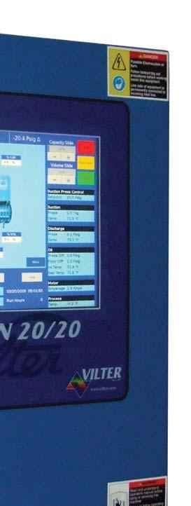
17 Section 3 Hardware Architecture Overview The Vission 20/20 control panel utilizes X-86 PC technology with a Linux operating system. For hardware architecture, see Figure 3-1 Hardware Architecture Overview. The Vission 20/20 has the following attributes: Low power, Industrial rated X-86 CPU. 15 XGA, high resolution LCD display. (Outdoor viewable LCD optional). 8-wire touch screen operator interface. Flexible and expandable I/O. NEMA-4 enclosure (NEMA-4X optional). Industrial temperature range design. Figure 3-1. Hardware Architecture Overview Vission 20/20 Operation and Service Manual Vilter/Emerson 35391SC
18 Section 3 Hardware Architecture Digital Input/Output (I/O) Refer to Table 2-1. Digital I/O. Compressor Start Output: When the Vission 20/20 signals the compressor to start, this output is energized. When the Vission 20/20 signals the compressor to stop, this output is de-energized. Oil Pump Start Output: When the Vission 20/20 signals the oil pump to start, this output is energized. When the Vission 20/20 signals the oil pump to stop, this output is de-energized. Capacity Increase Output: This output is only active when the compressor is running. When the Vission 20/20 determines that the compressor should increase capacity by moving the slide valve to a higher percentage, this output is energized. Once the slide valve reaches 100%, this output will not energize. Capacity Decrease Output: This output is only active when the compressor is running. When the Vission 20/20 determines that the compressor should decrease capacity by moving the slide valve to a lower percentage, this output is energized. Once the slide valve reaches 0%, this output will not energize. Volume Increase Output: This output is only active when the compressor is running. When the Vission 20/20 determines that the compressor should increase Volume Index (VI) by moving the volume slide to a higher percentage, this output is energized. Once the volume slide reaches 100%, this output will not energize. Volume Decrease Output: This output is only active when the compressor is running. When the Vission 20/20 determines that the compressor should decrease Volume Index (VI) by moving the volume slide to a lower percentage, this output is energized. Once the volume slide reaches 0%, this output will not energize. Oil Sump Heater Output: This output is active and energized when the oil separator temperature is lower than the oil separator temperature setpoint. It is de-energized when the oil separator temperature is higher than the oil separator temperature setpoint. Trip Output: This output is energized when the system has no Trips. If a trip is issued, the output de-energizes and stays de-energized until the trip condition is cleared. Slide Valve Setpoint #1 Output (Economizer): Normally used for an economizer solenoid, but could be used for other devices. When the compressor slide valve percentage is equal to or greater than slide valve set-point #1, the output is energized. When the compressor slide valve percentage is less than slide valve set-point #1, the output is de-energized. Slide Valve Setpoint #2 Output (Hot Gas): Normally used for a hot gas solenoid, but could be used for other devices. When the compressor slide valve percentage is equal to or greater than slide valve set-point #2, the output is energized. When the compressor slide valve percentage is less than slide valve set-point #2, the output is de-energized. Alarm Output: This output is energized when the system has no alarms. If an alarm is issued, the output de-energizes and stays de-energized until the alarm condition is cleared. Unused: This output has no current function. Liquid Injection #1 Output: If the compressor has liquid injection oil cooling, this output is active. When the compressor is running and the discharge temperature is above the oil separator temperature override setpoint and the oil separator temperature is above the override setpoint, then the output is energized. The output is de-energized when the discharge temperature falls below the on setpoint minus the solenoid differential. Liquid Injection #2 Output: Not Defined Remote Enabled Output: This output is energized when the Vission 20/20 panel is enabled for remote control. The compressor can be running or stopped, but is available to the remote system. If the compressor has an alarm or is placed into the manual stop position, this output is de-energized. Shunt Trip: Not defined. Comp Motor Starter Auxiliary Contact: This input looks for a feedback signal from the compressor starter, confirming that the compressor starter is energized. 3 2 Vission 20/20 Operation and Service Manual Vilter/Emerson 35391SC
19 Section 3 Hardware Architecture Table 3-1. Digital I/O (1 of 2) Board I/O # Description Type 1 1 Compressor Start OUTPUT 1 2 Oil Pump Start OUTPUT 1 3 Capacity Increase OUTPUT 1 4 Capacity Decrease OUTPUT 1 5 Volume Increase OUTPUT 1 6 Volume Decrease OUTPUT 1 7 Oil Separator Heater OUTPUT 2 8 Trip indicator (ON=Normal) OUTPUT 2 9 Slide Valve Set point #1 (Economizer) OUTPUT 2 10 Slide Valve Set point #2 (Hot Gas) OUTPUT 2 11 Alarm OUTPUT 2 12 Unused OUTPUT 2 13 Liquid Injection #1 OUTPUT 2 14 Liquid Injection #2 OUTPUT 2 15 Remote Enabled OUTPUT 2 16 Shunt Trip OUTPUT 3 17 Comp Motor Starter Auxiliary Contact INPUT 3 18 High Level Shutdown INPUT 3 19 Oil Level Float Switch #1 INPUT 3 20 Oil Level Float Switch #2 INPUT 3 21 Remote Setpoint #1/#2 Selection INPUT 3 22 Remote Start/Stop INPUT 3 23 Remote Capacity Increase INPUT 3 24 Remote Capacity Decrease INPUT 4 25 Condenser Step #1 OUTPUT 4 26 Condenser Step #2 OUTPUT 4 27 Condenser Step #3 OUTPUT 4 28 Condenser Step #4 OUTPUT 4 29 Auxiliary Input #1 INPUT 4 30 Auxiliary Input #2 INPUT 4 31 Auxiliary Input #3 INPUT 4 32 Auxiliary Input #4 INPUT Vission 20/20 Operation and Service Manual Vilter/Emerson 35391SC
20 Section 3 Hardware Architecture High Level Shutdown Input: This input must be energized in order for the compressor to operate. If de-energized, the compressor will shut down and issue a high level trip. Oil Level Float Switch #1 Input: Used for Cool Compression. Oil Level Float Switch #2 Input: Used for Cool Compression. Remote Select #1/#2 Input: This input enables or disables remote I/O control. Energizing this input enables the Remote Capacity Increase and Remote Capacity Decrease inputs. Remote Start/Stop Input: If the compressor is enabled for remote I/O control, this input is enabled. Energizing this input will issue a start for the compressor as long as it is available to run. De-energizing this input stops the compressor. Remote Capacity Increase Input: NOTE The scan interval on the remote increase and decrease inputs is approximately ONE SECOND. Please take that into account when developing a control scheme using the remote increase and remote decrease inputs for compressor control. If the compressor is enabled for remote I/O control, this input is enabled. Operational only when the compressor is running. Energizing this input will increase the slide valve position. The slide valve will continuously increase as long as this input is energized. The slide valve will not increase when this input is de-energized. Remote Capacity Decrease Input: Operational only when the compressor is running. This input is enabled if the compressor is enabled for remote I/O control. Energizing this input will decrease the slide valve position. The slide valve will continuously decrease as long as this input is energized. The slide valve will not decrease when this input is de-energized. Condenser Step #1 Output: This output is enabled when condenser control option is selected. A condenser fan or pump will be turned on or off by this output. Condenser Step #2 Output: This output is enabled when condenser control option is selected. A condenser fan or pump will be turned on or off by this output. Condenser Step #3 Output: This output is enabled when condenser control option is selected. A condenser fan or pump will be turned on or off by this output. Condenser Step #4 Output: This output is enabled when condenser control option is selected. A condenser fan or pump will be turned on or off by this output. Auxiliary Inputs #1 - #8: Optional inputs that can be configured as an alarm or trip. Typically connected to external switched devices. Auxiliary Outputs #1 - #4: Optional inputs that can be configured as an alarm or trip. Typically connected to external switched devices. Analog Inputs Refer to Table 2-2. Analog Inputs. Motor Current: Default is a 0-5 Amp current transformer (CT). Current transformer ratio is set in the calibration screen. Suction Pressure: Default signal is 4-20mA. Suction pressure transducer range and calibration is set in the calibration screen. Discharge Pressure Default signal is 4-20mA. Discharge pressure transducer range and calibration is set in the calibration screen. Oil Filter Inlet Pressure: Default signal is 4-20mA. Oil filter pressure transducer range and calibration is set in the calibration screen. Oil Manifold Pressure: Default signal is 4-20mA. Oil manifold pressure transducer range and calibration is set in the calibration screen. Economizer Pressure: Default signal is 4-20mA. Economizer pressure transducer range and calibration is set in the calibration screen. Slide Valve Position: Reads the 0-5 volt signal back from the slide position motor actuator to indicate current slide valve position. 3 4 Vission 20/20 Operation and Service Manual Vilter/Emerson 35391SC
21 Section 3 Hardware Architecture Table 3-1. Digital I/O (2 of 2) Board I/O # Description Type 5 33 Auxiliary Output #1 OUTPUT 5 34 Auxiliary Output #2 OUTPUT 5 35 Auxiliary Output #3 OUTPUT 5 36 Auxiliary Output #4 OUTPUT 5 37 Auxiliary Input #5 INPUT 5 38 Auxiliary Input #6 INPUT 5 39 Auxiliary Input #7 INPUT 5 40 Auxiliary Input #8 INPUT Table 3-2. Analog Inputs (1 of 2) Board I/O # Description Type 6 1 Motor Current 4-20 ma, 0-5A 6 2 Suction Pressure 0-5V, 1-5 V, 0-10V, 4-20 ma 6 3 Discharge Pressure 0-5V, 1-5 V, 0-10V, 4-20 ma 6 4 Oil Filter Inlet Pressure 0-5V, 1-5 V, 0-10V, 4-20 ma 6 5 Oil Manifold Pressure 0-5V, 1-5 V, 0-10V, 4-20 ma 6 6 Economizer Pressure 0-5V, 1-5 V, 0-10V, 4-20 ma 6 7 % Slide Valve Position 0-5V, 4-20 ma, Potentiometer 6 8 % Volume Position 0-5V, 4-20 ma, Potentiometer 7 9 Suction Temperature 4-20 ma, RTD, ICTD 7 10 Discharge Temperature 4-20 ma, RTD, ICTD 7 11 Oil Separator Temperature 4-20 ma, RTD, ICTD 7 12 Oil Manifold Temperature 4-20 ma, RTD, ICTD 7 13 Process Temperature 4-20 ma, RTD, ICTD 7 14 Chiller Inlet Temperature 4-20 ma, RTD, ICTD 7 15 Condenser Pressure 0-5V, 1-5 V, 0-10V, 4-20 ma, RTD, ICTD 7 16 Remote Caphold Setpoint 0-5V, 4-20 ma, RTD, ICTD 8 17 Auxiliary #1 0-5V, 1-5 V, 0-10V, 4-20 ma, RTD, ICTD 8 18 Auxiliary #2 0-5V, 1-5 V, 0-10V, 4-20 ma, RTD, ICTD 8 19 Auxiliary #3 0-5V, 1-5 V, 0-10V, 4-20 ma, RTD, ICTD 8 20 Auxiliary #4 0-5V, 1-5 V, 0-10V, 4-20 ma, RTD, ICTD 8 21 Auxiliary #5 0-5V, 1-5 V, 0-10V, 4-20 ma, RTD, ICTD 8 22 Auxiliary #6 0-5V, 1-5 V, 0-10V, 4-20 ma, RTD, ICTD 8 23 Auxiliary #7 0-5V, 1-5 V, 0-10V, 4-20 ma, RTD, ICTD 8 24 Auxiliary #8 0-5V, 1-5 V, 0-10V, 4-20 ma, RTD, ICTD 9 25 Auxiliary #9 0-5V, 1-5 V, 0-10V, 4-20 ma, RTD, ICTD 9 26 Auxiliary #10 0-5V, 1-5 V, 0-10V, 4-20 ma, RTD, ICTD 9 27 Auxiliary #11 0-5V, 1-5 V, 0-10V, 4-20 ma, RTD, ICTD Vission 20/20 Operation and Service Manual Vilter/Emerson 35391SC
22 Section 3 Hardware Architecture Volume Position: Reads the 0-5 volt signal back from the slide volume motor actuator to indicate current volume position. Suction Temperature: Default signal is RTD. Suction temperature calibration is set in the calibration screen. Discharge Temperature: Default signal is RTD. Discharge temperature calibration is set in the calibration screen. Oil Separator Temperature: Default signal is RTD. Oil separator temperature calibration is set in the calibration screen. Oil Manifold Temperature: Default signal is RTD. Oil manifold temperature calibration is set in the calibration screen. Process Temperature: Default signal is 4-20mA. Process temperature calibration and range are set in the calibration screen. Chiller Inlet Temperature: Default signal is 4-20mA. Measures separator level. Chiller Inlet Temperature calibration and range are set in the calibration screen. Condenser Pressure: Default signal is 4-20mA. Condenser pressure transducer range and calibration is set in the calibration screen. Remote Caphold: Default signal is 4-20mA. Active in Direct I/O mode. Adjusts the capacity of the compressor from 0-100%, proportional to the 4-20mA signal. Auxiliary #1 - #16: Flexible analog inputs that can be configured to control, alarm or trip. % Slide Valve Position: 4-20mA signal that transmits the slide valve position for remote monitoring. Motorized Valve (V+): For a cool compression compressor, this 4-20mA signal controls a motorized valve to regulate the liquid refrigerant level in the oil separator. For a liquid injection application on a standard single screw, this 4-20mA signal controls a motorized valve to regulate the liquid refrigerant injected into the compressor for oil cooling purposes. Digital & Analog I/O Boards Layout It is important to install the boards in the proper layout. For the correct digital and analog input/output (I/O) board layout, see Figure 3-2. Digital I/O Board Layout. Dipswitches Each board has a dipswitch which sets its communications address so that it can communicate with the CPU board. The dipswitch settings must be correct or the I/O will not function. Jumpers Jumpers are required on the analog boards to configure them for the type of sensors used. The jumper table for the analog board shows the optional jumper configurations for sensors other than the default Vilter standard. If a different sensor is to be used, the jumpers on the analog board need to be changed. In addition, the configuration for this sensor must be changed in the Instrument Calibration screen. The following illustrations show the Vilter default configurations for the Vission 20/20. Analog Outputs: Refer to Table 2-3. Analog Outputs. Compressor VFD: 4-20mA output to control compressor motor speed with a Variable Frequency Drive (VFD). Condenser VFD: 4-20mA output to control one condenser fan which is interleaved between the remaining condenser steps for smoother control. 3 6 Vission 20/20 Operation and Service Manual Vilter/Emerson 35391SC
 Board I/O # Description Type 9 28 Auxiliary #12 0-5V, 1-5 V, 0-10V, 4-20 ma, RTD, ICTD 9 29 Auxiliary #13 0-5V, 1-5 V, 0-10V, 4-20 ma, RTD, ICTD 9 30 Auxiliary #14 0-5V, 1-5 V,")
23 Section 3 Hardware Architecture Table 3-2. Analog Inputs (2 of 2) Board I/O # Description Type 9 28 Auxiliary #12 0-5V, 1-5 V, 0-10V, 4-20 ma, RTD, ICTD 9 29 Auxiliary #13 0-5V, 1-5 V, 0-10V, 4-20 ma, RTD, ICTD 9 30 Auxiliary #14 0-5V, 1-5 V, 0-10V, 4-20 ma, RTD, ICTD 9 31 Auxiliary #15 0-5V, 1-5 V, 0-10V, 4-20 ma, RTD, ICTD 9 32 Auxiliary #16 0-5V, 1-5 V, 0-10V, 4-20 ma, RTD, ICTD Table 3-3. Analog Outputs Board I/O # Description Type 10 1 Compressor VFD 4-20 ma 10 2 Condenser VFD 4-20 ma 10 3 % Slide Valve Position 4-20 ma 10 4 Motorized Valve (Cool Compression or Liquid Injection), V ma 10 5 Spare / Unused 4-20 ma 10 6 Spare / Unused 4-20 ma 10 7 Spare / Unused 4-20 ma 10 8 Spare / Unused 4-20 ma Figure 3-2. Digital I/O Board Layout Vission 20/20 Operation and Service Manual Vilter/Emerson 35391SC


24 Section 3 Hardware Architecture Digital Output Boards The digital output board convert signals generated by the Vission 20/20 program into 120Vac signals that can be energize or signal other devices. All the signals are digital in that the only two states available or either on or off. See board layout, Figure 3-3. Digital Output Board Layout. Signal LED s: Marked in the diagram below in Blue. These LED s indicated when a 120Vac output is being produced. Voltage LED s: Marked in the diagram below in Orange. These LED s indicated the correct voltage of both the 5Vdc and 24Vdc power sources. Communication LED s: Marked in the diagram below in Green. These LED s Show the active communications between the digital output board and the Vission 20/20 CPU board. Address Dipswitches: Marked in the diagram below in Red. These dipswitches are used to assign each board its address position. The addresses are binary and therefor the address of a digital output board will either be address as 1 (0001) or 2 (0010). Figure 3-3. Digital Output Board Layout 3 8 Vission 20/20 Operation and Service Manual Vilter/Emerson 35391SC


25 Section 3 Hardware Architecture Digital Input Boards The digital input board convert 120Vdc signals from external devices to signal for the Vission 20/20 program. All the signals are digital in that the only two states available or either on or off. See board layout, Figure 3-4. Digital Input Board Layout. Signal LEDs: Marked in the diagram below in light Blue. These LEDs indicated when a 120Vac input is detected. Voltage LEDs: Marked in the diagram below in Orange. These LEDs indicated the correct voltage of both the 5Vdc and 24Vdc power sources. Communication LEDs: Marked in the diagram below in Green. These LEDs Show the active communications between the digital output board and the Vission 20/20 CPU board. Address Dipswitches: Marked in the diagram below in Red. These dipswitches are used to assign each board its address position. The addresses are binary and therefor the address of a digital input board can only be addressed as 3 (0011). Figure 3-4. Digital Input Board Layout Vission 20/20 Operation and Service Manual Vilter/Emerson 35391SC


26 Section 3 Hardware Architecture Digital In-Out Boards The digital input - output board convert signals generated by the Vission 20/20 program into 120Vac signals as well as detect external 120Vac inputs to signal the Vission 20/20 program. All the signals are digital in that the only two states available or either on or off. See board layout, Figure 3-5. Digital Input-Output Board Layout. Signal LEDs: Marked in the diagram below in Blue or outputs and light blue for inputs. These LEDs indicate when a 120Vac output is being produced or a 120Vac signal is detected. Voltage LEDs: Marked in the diagram below in Orange. These LEDs indicated the correct voltage of both the 5Vdc and 24Vdc power sources. Communication LEDs: Marked in the diagram below in Green. These LEDs show the active communications between the digital output board and the Vission 20/20 CPU board. Address Dipswitches: Marked in the diagram below in Red. These dipswitches are used to assign each board its address position. The addresses are binary and therefore the address of a digital output board will either be address as 4 (0100) or 5 (0101). Figure 3-5. Digital Input-Output Board Layout 3 10 Vission 20/20 Operation and Service Manual Vilter/Emerson 35391SC


27 Section 3 Hardware Architecture Analog Input Boards The analog input board convert varying DC signals into a signal that can interpreted by the Vission 20/20 program. The signals are considered analog because the input DC signal can vary from the minimum value to the maximum value. See board layout, Figure 3-6. Analog Input Board Layout. Configuration Jumpers: Marked in the diagram below in Purple. The jumpers allow the operator to configure the signal type and range for incoming analog signals. For the correct jumper setting for a giving application, see Table 2-4. Analog Input Jumper Tables. Voltage LEDs: Marked in the diagram below in Orange. These LEDs indicated the correct voltage of both the 5Vdc and 24Vdc power sources. Communication LEDs: Marked in the diagram below in Green. These LEDs Show the active communications between the digital output board and the Vission 20/20 CPU board. Address Dipswitches: Marked in the diagram below in Red. These dipswitches are used to assign each board its address position. The addresses are binary and therefore the address of a digital output board will be address as 6 (0110), 7 (0111), 8 (1000) or 9 (1001). Figure 3-6. Analog Input Board Layout Vission 20/20 Operation and Service Manual Vilter/Emerson 35391SC
28 Section 3 Hardware Architecture Analog Input Jumper Tables The following tables are used to configure each channel of the analog input board signal type and range desired by the operator, see Table 2-4. Analog Input Jumper Tables. Table 3-4. Analog Input Jumper Tables CHANNEL 1 SIGNAL JP-1 JP-2 JP-3 JP-27 JP-35 Analog Input 1-A* 0-5 AMP OUT OUT OUT OUT IN Analog input 1-B** 0-5 VOLT OUT OUT OUT OUT OUT 1-5 VOLT OUT OUT OUT OUT OUT 0-10 VOLT OUT OUT IN OUT OUT 4-20 ma IN OUT OUT OUT OUT ICTD OUT IN OUT OUT OUT RTD OUT OUT OUT IN OUT *Use Analog Input 1-A when 0-5 AMP secondary current transformers are installed in the motor starter. **Use Analog Input 1-B when current transformers are installed in the motor starter. CHANNEL 2 SIGNAL JP-4 JP-5 JP-6 JP-28 Analog Input VOLT OUT OUT OUT OUT 1-5 VOLT OUT OUT OUT OUT 0-10 VOLT OUT OUT IN OUT 4-20 ma IN OUT OUT OUT ICTD OUT IN OUT OUT RTD OUT OUT OUT IN CHANNEL 3 SIGNAL JP-7 JP-8 JP-9 JP-29 Analog Input VOLT OUT OUT OUT OUT 1-5 VOLT OUT OUT OUT OUT 0-10 VOLT OUT OUT IN OUT 4-20 ma IN OUT OUT OUT ICTD OUT IN OUT OUT RTD OUT OUT OUT IN CHANNEL 4 SIGNAL JP-10 JP-11 JP-12 JP-30 Analog Input VOLT OUT OUT OUT OUT 1-5 VOLT OUT OUT OUT OUT 0-10 VOLT OUT OUT IN OUT 4-20 ma IN OUT OUT OUT ICTD OUT IN OUT OUT RTD OUT OUT OUT IN 3 12 Vission 20/20 Operation and Service Manual Vilter/Emerson 35391SC
29 Section 3 Hardware Architecture Table 3-4. Analog Input Jumper Tables (Continued) CHANNEL 5 SIGNAL JP-13 JP-14 JP-15 JP-31 Analog Input VOLT OUT OUT OUT OUT 1-5 VOLT OUT OUT OUT OUT 0-10 VOLT OUT OUT IN OUT 4-20 ma IN OUT OUT OUT ICTD OUT IN OUT OUT RTD OUT OUT OUT IN CHANNEL 6 SIGNAL JP-16 JP-17 JP-18 JP-32 Analog Input VOLT OUT OUT OUT OUT 1-5 VOLT OUT OUT OUT OUT 0-10 VOLT OUT OUT IN OUT 4-20 ma IN OUT OUT OUT ICTD OUT IN OUT OUT RTD OUT OUT OUT IN CHANNEL 7 SIGNAL JP-19 JP-20 JP-21 JP-33 JP-25 Analog Input VOLT OUT OUT OUT OUT VOLT OUT OUT OUT OUT VOLT OUT OUT IN OUT ma IN OUT OUT OUT 2 ICTD OUT IN OUT OUT 2 RTD OUT OUT OUT IN 2 ACTUATOR OUT OUT OUT OUT 1 POTENTIOMETER OUT OUT OUT OUT 3 CHANNEL 8 SIGNAL JP-22 JP-23 JP-24 JP-34 JP-26 Analog Input VOLT OUT OUT OUT OUT VOLT OUT OUT OUT OUT VOLT OUT OUT IN OUT ma IN OUT OUT OUT 2 ICTD OUT IN OUT OUT 2 RTD OUT OUT OUT IN 2 ACTUATOR OUT OUT OUT OUT 1 POTENTIOMETER OUT OUT OUT OUT 3 Vission 20/20 Operation and Service Manual Vilter/Emerson 35391SC


. Figure 3-7.")
30 Section 3 Hardware Architecture Analog Output Boards The Analog Output board convert signals form the Vission 20/20 program into a current ranging from 4mA to 20mA, see Figure 3-7. Analog Output Board Layout. Voltage LEDs: Marked in the diagram below in Orange. These LEDs indicated the correct voltage of both the 5Vdc and 24Vdc power sources. Communication LED s: Marked in the diagram below in Green. These LEDs show the active communications between the digital output board and the Vission 20/20 CPU board. Address Dipswitches: Marked in the diagram below in Red. These dipswitches are used to assign each board its address position. The addresses are binary and therefore the address of a digital output board will only be addressed as 10 (1010). Figure 3-7. Analog Output Board Layout 3 14 Vission 20/20 Operation and Service Manual Vilter/Emerson 35391SC

31 Section 4 Main Screen Overview The Main Screen is the first screen encountered when powering up the Vission 20/20 Panel, see Figure 4-1. Main Screen. This screen is designed as the starting point for all succeeding screens and provides as much information as possible at a glance. The Main Screen is divided into four sections. Three of the sections are static; Top Status Bar, Bottom Status Bar and Parameters Bar. These three sections of the main screen will remain visible while navigating through other screens and provide a constant view of critical information. The splash screen is the only dynamic section. All navigation to any other screens will be performed through the Main Screen. Figure 4-1. Main Screen Vission 20/20 Operation and Service Manual Vilter/Emerson 35391SC
32 Section 4 Main Screen Top Status Bar The standard view of the status bar shows three pieces of information. From left to right, the bar shows the control method, the current run mode, and the difference between the desired control setpoint and the actual value of the processes control value, see Figure 4-2. Top Status Bar. The status bar also has an alternate function where it displays to the user any information that requires user attention or intervention. It accomplishes this by changing the status bar s color and/or flashing a additional information bars over the standard status bar view. Standard Bar blue: Indicates a condition where the compressor motor is not running. Standard Bar green: Informs the operator that the compressor motor is currently running. Information Bars will flash their information over the top of the status bar. The operator will see the status bar and then one or more information bars in a repetitive sequence. Information Bar blue: Shows various operational modes that are different than normal running condition. An example of this would be a load limit condition. The compressor is not able to completely load due to some parameter like high motor current and therefore the operator is notified via this type of information bar. Information bar yellow This typically indicates an Alarm condition. Alarm conditions do not stop the compressor but it is meant to alert the operator of conditions that if corrective action is not taken, then a compressor trip can result. Information bar red Informs the operator that the compressor motor was stopped due the condition listed in the information bar. Compressor trips are designed to protect the equipment and any personnel operating the equipment. Figure 4-2. Top Status Bar 4 2 Vission 20/20 Operation and Service Manual Vilter/Emerson 35391SC

33 Section 4 Main Screen Parameter Bar The main purpose of the Parameter Bar is to display the common operational parameters that the operator would be most concerned with. It also gives the operator access to critical buttons such as the stop and start buttons, see Figure 4-3. Parameter Bar. Capacity Slide Indicator: Shows the position of the capacity slide from 0% to 100% via a horizontal blue bar. The buttons below the indicator are used in manual capacity control. The - button will decrease the capacity position and the + button will increase the position. Volume Slide Indicator: Shows the position of the volume slide from 0% to 100% via a horizontal blue bar. In some cases, increase and decrease buttons will appear below the volume indicator. The buttons only appear if the operator who is logged on has sufficient privileges. If available, the buttons work to increase and decrease the volume slide position in the same manner as the capacity slide. Stop Button: When pressed, stops the compressor in all cases. Remote Lock Out Button: When pressed, activates the remote lock out option. This is a safety feature that prevents any external devices from assuming control and starting the compressor. To release the remote lock out, the operator must press the unit start button and then the remote button when the start dialog box appears. Alarm Reset Button: When pressed, clears any current alarms, trips or status messages that may be displayed on the information bar. Note, if the condition that created the alarm, trip or status message still exits, the message will reappear. Figure 4-3. Parameter Bar Vission 20/20 Operation and Service Manual Vilter/Emerson 35391SC


34 Section 4 Main Screen Parameter Bar (Continued) Unit Start Button: When pressed, a start dialog box will appear that will give the operator a number of run options; Auto, Manual, Remote, or auto sequencing, see Figure 4-4. Unit Start Pop-Up Window. Control Parameter Boxes: The parameter boxes provide updated data on several key control parameters. The top box indicates the desired control setpoint that is set in the Compressor Control Screen. In the case that the Run mode is in remote capacity control, this box will show the desired capacity position. The suction box shows the current suction pressure and suction temperature. The discharge box shows the current discharge pressure and discharge temperature. The oil box shows the pressure differential which is calculated as oil filter out pressure minus suction pressure. Filter differential is calculated as oil filter in pressure minus oil filter out pressure. Inj Temp is the temperature of the oil at the oil injection port and Sep Temp is the temperature of the oil in the separator. The motor box shows the motor current. Figure 4-4. Unit Start Pop-Up Window 4 4 Vission 20/20 Operation and Service Manual Vilter/Emerson 35391SC

35 Section 4 Main Screen Bottom Status Bar The bottom status bar gives the operator easy access to some basic functions and information. The functions are available via the four button, see Figure 4-5. Bottom Status Bar. Maintenance Button: Pressing the maintenance button will give the operator access to the maintenance charts and sign off tables. User Access Button: This button takes the operator to another login screen to create additional users. Log off Button: Pressing the log off button logs off the correct user if any are logged in. Help Button: Pressing the help button takes the operator to the help screen where the operator can access an operation and service manual and also get access to program information. Status Bars The information available is provide by two status bars, one for maintenance activities and the other for any alarms or trips that might be active. To the right of the status bars are positions for displaying the current user (if any are logged in), the date and time, and the total run hours of the compressor. Figure 4-5. Bottom Status Bar Vission 20/20 Operation and Service Manual Vilter/Emerson 35391SC

36 Section 4 Main Screen Splash Screen The splash screen is the dynamic portion of the screen that will change as the operator navigates through the Vission 20/20 panel screen, see Figure 4-6. Splash Screen. The main screen shows a graphic of a Vilter compressor with a number of data boxes spread across the screen. Also on the top left are several indicators. Discharge: Displays the discharge pressure and temperature. Oil Filter: Displays the oil filter inlet pressure, oil filter outlet pressure, and oil differential pressure across the oil filter. Suction: Displays the suction pressure and temperature. Motor: Displays the motor current. When the motor VFD is enabled, this box will also display the motor RPM. Separator: Displays the temperature of the oil in the separator. % Cap: Displays the position of the capacity slide from 0% to 100%. Process: When the Process control is selected as the control mode, this box will appear and displays the process temperature. % Vol: Displays the position of the volume slide from 0% to 100%. Anti-Recycle: Displays the anti-recycle time, if applicable. Oil Pump: The oil pump on a Vilter compressor often cycles on and off depending on differential pressure. This indicator informs the operator when the oil pump is running. Oil Heater: The oil heater often cycles on and off depending on the separator oil temperature. This indicator informs the operator when the oil heater is on. Remote lock out: Displays the current status of the remote lock out. While on, no system controller can remotely assume control of the Vission 20/20 panel and start the compressor. Menu Button: When pressed, navigates the operator to the menu screen. Figure 4-6. Splash Screen 4 6 Vission 20/20 Operation and Service Manual Vilter/Emerson 35391SC

37 Section 5 Menu Screen Overview The menu screen is the launching point to every other section of the Vission 20/20 panel software. Every screen navigated to from this screen will return to the menu screen upon exiting, see Figure 5-1. Menu Screen. Navigation Buttons Compressor control: Navigates to the compressor control screen where the operator can set the various compressor control parameters. Alarms and trips: Navigates to the alarms and trips screen where the operator can set the various alarm and trip parameters. Timers: Navigates to the timer screen where the operator can set the various time related parameters. Compressor scheduling: Navigates to the compressor scheduling screen where the operator can set the scheduler to change the control method at settable dates and times. Compressor sequencing: Navigates to the compressor sequencing screen where the operator can set-up compressor to sequence up to four other compressors. This is also sometimes known as lead-lag control. Condenser control: Navigates to the condenser control screen where the operator can set up local condenser control parameter. Vilter VFD: Not currently available. Service options: Navigates to the service options screen where the operator can manually turn on/off digital and analog outputs for maintenance and diagnostics purposes. Figure 5-1. Menu Screen Vission 20/20 Operation and Service Manual Vilter/Emerson 35391SC
38 Section 5 Menu Screen Instrument calibration: Navigates to the instrument calibration screen where the operator can calibrate all of the system sensors. Slide calibration: Navigates to the slide calibration screen where the operator can calibrate the capacity and volume slide actuators. Trend chart: Navigates to the trend chart screen where the operator can select up to four parameters for graphical historical data trending. Event list: Navigates to the event list screen where the operator can view the systems events such as trips or alarms in descending chronological order. Input/output states: Allows viewing of the live data of all analog and digital input and outputs. Also allows viewing of a snap shot of all analog and digital input and outputs at the time of the last compressor fault event. Auxiliary I/O Navigates to the auxiliary I/O screen where an operator can configure any auxiliary instruments or devices. Configuration: Navigates to configuration screens where the initial system parameters are configured. Data backup: Allows the operator to backup setpoints, configuration parameters, and calibration settings to a USB memory device. In addition, this allows the restoration of previously saved database files. Main: Navigates back to the main screen. 5 2 Vission 20/20 Operation and Service Manual Vilter/Emerson 35391SC


39 Section 6 Compressor Control Overview The compressor control screen is where an operator can set the majority of the compressor settings. These setting define how the compressor will operate and respond to changing loads. The compressor control screen consists of several screens but in order not to overwhelm the operator with options, many of the screens may not be visible. How the compressor is configured in the configuration screen will determine what screens are displayed. It is important to note that there isn t one correct way to set these parameters. Every application is different and requires the operator to tune these settings to achieve the best operation, see Figure 6-1. Compressor Control Screen. Pulse Proportional Control The Vission 20/20 uses a pulse proportional control method to control the compressor capacity slide valve in order to maintain the control setpoint. The control setpoint can either be process temperature control setpoint or suction pressure control setpoint depending on what the operator has selected as the control mode. The proportion control uses the Interval Time Setpoint to define the time the algorithm waits to read the current setpoint and calculates the error from the process control setpoint. Based on the error from setpoint, the algorithm calculates a pulse time in which the capacity slide is moved in the direction of the error. The further away the process variable is from the control setpoint, the larger the corrective pulse will be. The duration of the pulse is limited by the Pulse Time Setpoint. By default the maximum pulse time is the same as the interval time. This means that the pulse time can be 100% of the interval time given a near continuous movement of the capacity slide. Adjusting these setpoints can be useful in slowing down the reaction time of the compressor if large thermal time contents are present in the refrigeration cycle. Figure 6-1. Compressor Control Screen Vission 20/20 Operation and Service Manual Vilter/Emerson 35391SC


40 Section 6 Compressor Control As mentioned in the above paragraph, the distance of the process variable from the control setpoint determines the size of the pulse used to move the capacity slide. This is called the proportional band and is set by the Proportional Setpoint. When the process variable is outside the proportional band, the slide will move in the direction of the error continuously. Increasing the size of the proportional band can help slow the compressors reaction by varying loads if desired, see Figure 6-2. Proportional Band & Setpoint. The Dead Band Setpoint defines area around the control setpoint where the algorithm stops adjusting the capacity slide. This area is a percentage of the proportional band. By default the proportional band is set to 4 Psig and the dead band is set to 10% of 4 Psig. Making the dead band +/- 0.4 Psig of the control setpoint. Once the process variable is within the dead band, the algorithm considers the compressor to be on setpoint. If the operator wishes the compressor to operate closer, the setpoint can be set to a smaller percentage. However this will result in the capacity slide excessively moving to maintain the setpoint and could over heat the actuator or shorten the actuators operational life. Auto-Cycle The auto-cycle setpoints define the control points in which the compressor will automatically cycle on and off when the compressor has been placed into Auto run mode. These setpoints can be enabled or disabled using the check box. A delay can be entered to momentarily delay the start or stop from immediately occurring when the setpoint is met. If a compressor shutdown is desired on a suction pressure drop and a manual reset is required, set the OFF value below the Low Suction Pressure safety trip value. This will shut down the compressor and a Reset will be required to restart it. Figure 6-2. Proportional Band & Setpoint 6 2 Vission 20/20 Operation and Service Manual Vilter/Emerson 35391SC

41 Section 6 Compressor Control The auto-cycle function will operate only in local Auto mode and Direct I/O Remote Auto mode. If the auto-cycle feature is enabled while running in any other remote mode, the function will simply be ignored. However, the Minimum slide position will continue to be respected in Remote Auto mode. If the compressor changes from a remote mode back to Local Auto mode, the auto-cycle feature will operate normally. NOTE When the Pump-down Feature is enabled, the Autocycle setpoints are automatically disabled. Pumpdown mode will cause the compressor to cycle off via the Pump-down Stop Pressure setpoint, and will not allow the compressor to start again. Enable: Enables the Auto-cycle control. Uncheck the box to disable the Auto-cycle set-points. Start Pressure: When the suction pressure meets or exceeds this setpoint, the compressor will start. Start Delay: Delays the compressor from starting when the suction pressure meets or exceeds this setpoint. Stop Pressure: When the suction pressure meets or falls below this setpoint, the compressor will stop. Stop Delay: Delays the compressor from stopping when the suction pressure meets or exceeds this setpoint. Minimum Slide Position: The minimum capacity slide position that the compressor is allowed to run at. Variable Frequency Drive (VFD) The VFD page is where the operator can tune the motor VFD for desired operation. A Vilter compressor uses the variable speed of a VFD controlled motor to vary the amount of work or capacity of the compressor. The basic one step VFD control will use the capacity slide to control the first half of the total available capacity and the motor speed to control the second half of the total available capacity, see Figure 6-3. VFD One-Step Control Method. For example, if the compressor needs to load to 100% of its capacity. The control algorithm will first move the capacity slide to its maximum position, then the motor speed will ramp up to its maximum speed. In the unloading direction, the motor speed will ramp down to its minimum speed, then the capacity slide will move to its minimum position. The two-step control method works much like the onestep method but divides the control into four sections, see Figure 6-4. VFD Two-Step Control Method. While loading; the compressor will first move the capacity slide to the maximum set for step one then speed up the motor to its maximum speed for the same step. Once step one has completed, the control algorithm will again move the capacity slide to the maximum position and the maximum speed of step two. At this point the compressor would be fully loaded. Unloading occurs in the reverse direction. The two-step control method is not typical for most installations and is normally used when a Vilter engineer recommends it. Figure 6-3. VFD One-Step Control Method Figure 6-4. VFD Two-Step Control Method Vission 20/20 Operation and Service Manual Vilter/Emerson 35391SC
42 Section 6 Compressor Control NOTE VFD installation is not covered in this manual. A VFD that is not properly installed and configured has the potential of causing intermittent and dangerous problems. Please consult your VFD manual. for how fast the error is changing, positively or negatively. A standard PID loop variable, it is not used for our applications. Pumpdown Control 1 Step VFD Control: Enables the first step in the VFD control algorithm. This check box is not deselectable by the operator. Capacity Slide Position: Defines the minimum and maximum positions for the capacity slide. While in 1 step control these values should be 0% for minimum and 100% for maximum. VFD Speed: Defines the minimum and maximum speed for the motor speed. While in 1 step control these values should reflect the full range of the VFD. 2 Step VFD Control: Enables the second step in the VFD control algorithm. Capacity Slide Position: Defines the minimum and maximum position of the capacity slide in the 2 step VFD control. VFD Speed: Defines the minimum and maximum speed for the motor in the 2 step VFD control. P = Proportional (gain) setpoint: Used to adjust the motor speed action in direct proportion to the difference between the control setpoint and the process variable (SP - PV error). This is a unit-less quantity and is used for coarse adjustment. This setpoint should be set to the lowest value that gives adequate control system response. Increasing the proportional setting increases the control system s sensitivity to small process fluctuations and the tendency to hunt. I = Integral (reset) setpoint: Used to adjust the capacity control action, integrating the error over time, to account for a small error that has persisted for a long time. This quantity is used for fine adjustment. This setpoint is used to smooth out process variations. This setpoint should be set high enough to prevent hunting but low enough to prevent control system overshoot. D = Derivative (rate) setpoint: Used to adjust the capacity control action, accounting The Pumpdown Control defines a method of pumping down a chiller, which is to draw off refrigerant from the chiller. This feature can be enabled or disabled from this menu which is the part of Compressor Control Screen. If Pumpdown is enabled, this feature will only function when the compressor is running in local Auto Mode and Control Mode Configured is Suction Pressure. If Pumpdown Feature is enabled, then; The Auto-cycle functionality is ignored. Pumpdown mode will cause the compressor to cycle off via the Pumpdown Stop Pressure setpoint. Normally, the Pumpdown Stop Pressure setpoint will be set lower than the Auto-cycle Stop setpoint. Therefore, as the suction pressure is pulled down, the compressor is prevented from shutting down prematurely via the Auto-cycle Stop setpoint by automatically ignoring the Auto-cycle feature. The compressor will be placed into Stop mode after the suction pressure is equal to, or goes below the Pumpdown Stop Pressure. Pumpdown: This checkbox enables the Pumpdown feature. If this box is unchecked, Pumpdown setpoints are ignored and the user is not allowed to edit Pumpdown setpoints. Stop Pressure: This setpoint defines the suction pressure value at which the compressor will cycle off. Normally, this setpoint is set below the Suction Pressure Auto-cycle Stop Pressure setpoint. Stop Delay: This setpoint delays the compressor from stopping when the suction pressure is equal to or less than the Stop Pressure. Min Slide Position: The minimum capacity slide is the setpoint that the compressor is allowed to run at. By forcing the compressor capacity to operate at a value above minimum, we insure that the suction pressure will be pulled down to the Stop Pressure setpoint. Pumpdown Operation (Run/Stop): This button starts/stops the Pumpdown operation. 6 4 Vission 20/20 Operation and Service Manual Vilter/Emerson 35391SC
43 Section 6 Compressor Control This button is active only when compressor is in local Auto mode and Control Mode Configured is Suction Pressure. This button will display Run when Pumpdown operation has not started or stopped, while button will display Stop when Pumpdown operation is running. When Pumpdown feature is enabled, Pulldown checkbox is automatically grayed out. Similarly when Pulldown feature is enabled, Pumpdown checkbox is automatically grayed out and hence, the user will not be able to operate Pumpdown feature. This is done to keep Pumpdown and Pulldown features mutually exclusive. Pulldown Control The Pulldown Control defines a method of slowly pulling the suction pressure down from a high value. This is sometimes required on systems that have liquid recirculation systems or on new building to prevent structural damage by limiting the rate at which to build is cooled. This feature can be enabled or disabled from this menu which is the part of Compressor Control Screen. If Pulldown is enabled, this feature will only function when the compressor is running in local Auto, Auto Sequencing mode and the Control mode is Suction Pressure 1. The Pulldown feature provides a method to slowly pull the suction pressure down to operating conditions. The pulldown method used is to step the suction pressure down over a defined time interval. Example: Assume the suction pressure is at 85 psig and the setpoint we want to get to is 20 psig. The operator wants to allow 48 hours of pulldown time. Pick a reasonable step pressure of 5 psig for every step. This defines a change of (80 20 = 60) psig. Note: First step is applied immediately. So first step starts at (85 5 = 80) psig Number of steps = delta 60 psig change * 1 step/5 psig = 12 steps. Delay per Step = 48 hours / 12 steps = 4 hours/step. So for the first 4 hours, the compressor runs at 80 psig. Next 4 75 psig Next 4 70 psig And so forth. After the 12th step (running at 25 psig), 48 hours will have elapsed, and the new setpoint becomes 20 psig, achieving the 20 psig setpoint after 48 hours. After the pulldown setpoint is equal to or is less than the control setpoint, the pulldown feature will disable itself. Pulldown: This checkbox enables the Pulldown feature. If this box is unchecked, Pulldown setpoints are ignored and the operator is not allowed to edit Pulldown setpoints. Initiate Pulldown at Next Start: This checkbox when enabled, turns on the Pulldown process at the next start cycle, Pulldown operation will work in the following manners: Pulldown only works when Control mode is Suction Pressure 1. If not started in Suction Pressure 1 then Pulldown process will not run until stopped and restarted in Suction Pressure 1. If started in Suction Pressure 1 and changed after start, then Pulldown process will be suspended and restart once Control mode is changed back to Suction Pressure 1. Step Pressure: This setpoint defines the step decrements at which the suction pressure value will be controlled at. Delay Per Step: This setpoint defines the time increment at which the compressor will be controlled at each step. Stop Pressure: This setpoint defines the suction pressure value at which Pulldown operation will get completed. When suction pressure value is equal to or goes below this setpoint, Pulldown feature disables itself. Also Pulldown and Initiate Pulldown at Next Start checkboxes will be automatically deselected as normally this is one time use feature. Auto Cycle Differential: This setpoint defines the offset pressure values for Auto Cycle Start Pressure and Stop Pressure from the Suction Pressure setpoint. Auto Cycle Start Pressure setpoint will be Suction Pressure setpoint incremented by this setpoint pressure value, while Auto Cycle Stop Pressure value will be Suction Pressure setpoint decremented by this setpoint pressure value. When Pulldown feature is enabled, Pumpdown checkbox is automatically grayed out. Similarly when Pumpdown feature is enabled, Pulldown checkbox is automatically Vission 20/20 Operation and Service Manual Vilter/Emerson 35391SC
44 Section 6 Compressor Control grayed out and hence, the user will not be able to operate Pulldown feature. This is done to keep Pulldown & Pumpdown features mutually exclusive. Control Mode This drop down box gives the operator the ability to change the type of control mode such as suction pressure control or process temperature control. The operator can also switch from setpoint 1 and setpoint 2 for each control method. What is available in this dropdown box is dependent on the number and type of control selected in the configuration screen. Stop Load and Force Unload The stop load and force unload feature s primary purpose is to attempt to prevent the compressor from tripping off due to particular instrument reading. For example, if the suction pressure drops too low, the compressor will trip off for safety reasons. However, the stop load & force unload algorithm recognizes a potential trip and either stops the compressor from loading up or even unloads the compressor to prevent the trip. Stop load: When this value is reached, the capacity slide will not advance in any condition. Force Unload: When this value is reached, the capacity slide position will decrease until the variable reading is below this value. High Motor Amps: Motor current values for stop load and force unload. High Discharge Pressure: Discharge pressure value for stop load and force unload. Low Suction Pressure: Suction pressure values for stop load and force unload Capacity Slide Triggered Outputs The Vission 20/20 offers two digital outputs that can be triggered at a specified capacity slide position. By default, the outputs are preselected for economizer and hot gas bypass. However, these preselected outputs are customizable by the operator. Slide Valve Setpoint: Operator editable labels for the each output. Slide %: Indicates the capacity slide position where the digital output is triggered. State Below Setpoint: Defines the state of the digital output when the slide position is below the Slide % setpoint. The operator can choose between N.O. or N.C. Active: Check box to enable the digital output. Volume Slide Position Offset These setpoints offer the ability to alter the Volume position table to take advantage of potential energy savings. Since the volume position is a function of the capacity position, the offset to the volume is based on the position of the capacity slide. The volume offset can be applied to the entire capacity slide range or just a portion using the Capacity Range minimum and maximum setpoints. Volume Slide Adjustment %: The value in percentage of the volume slide offset. Capacity Range: Defines the range that the volume position slide offset will be applied. Soft Load This setpoint is used to slow the loading of the compressor. In some refrigeration systems, a loading compressor can have dramatic effects on the system parameters. This setpoint allows an operator to reduce the continuous load pulse as defined in the proportional control section to a percent duty cycle. Soft load %: Defines the duty cycle of the continuous load pulse. At 100%, the continuous pulse will truly be continuous. At 50%, the continuous pulse would be reduced to half time on and half time off in the time interval defined in the proportional control section. 6 6 Vission 20/20 Operation and Service Manual Vilter/Emerson 35391SC
45 Section 6 Compressor Control Load Anticipating The purpose of the load anticipating algorithm is to reduce the amount of overshoot of the capacity slide position while the compressor attempts to meet the control setpoint. This advanced feature of the Vission 20/20 closely monitors the rate of change of the process variable and compares it to the control setpoint. If the process variable is changing in the direction of the control setpoint at the specified rate or greater, then the normal command to move the capacity slide is interrupted. The rate is calculated between time intervals set in the proportional control section of this screen. Enable Load Anticipation Algorithm: Allows the operator to choose if the load anticipation algorithm runs. Rate Dead Band: Defines the rate at which the capacity slide movement will be interrupted. This value is an absolute value of the process variable. For example, the default value is If the control mode is suction pressure, then this value is 0.25 Psig or if process temperature is the control mode then the value would be 0.25 F. Oil Control These setpoints determine how the Vission 20/20 will manage the oil of the compressor. Oil Pump Press Restart Ratio: The on and off setpoints define when the oil pump will cycle on and off if the oil pump is selected to cycle from the configuration screen. Oil Separator Heater Temp: When the oil temperature falls below this setpoint the oil heater will turn on. Note, there is a 5 F differential associated with this setpoint. For example, when set at 100 F, the heater will turn on at 95 F and off at 105 F. Liquid Injection The setpoints is this section are to control the behavior of the liquid refrigerant injected into the compressor for oil cooling purposes. The liquid injection solenoid control is based off of discharge temperature whether the compressor uses just an injection solenoid or a motorized valve in conjunction with the solenoid. Vission 20/20 Operation and Service Manual Vilter/Emerson 35391SC Liquid Injection Solenoid Control ONLY When using only the liquid injection solenoid, the solenoid is activated once the value of discharge temperature meets or exceeds the value of Liquid inj. Setpoint 1 and the value of oil separator temperature meets or exceeds the value of Oil Sep. Temp. Override. The injection solenoid will deactivate if either of setpoints are not met. This will prevent situations where the discharge temperature may rise quickly, but the oil temperature is still very cold. By preventing the liquid injection solenoid from turning on at this point, the oil separator will not be subjected to additional liquid refrigerant, that would cool the oil even further. Liquid Injection Control using a 4-20ma motorized valve. When a motorized valve is used to control the amount of liquid being injected into the compressor the previously mentioned setpoints have a slightly different function. The Oil Sep. Temp. Override is still used in controlling the injection solenoid, however the Liquid Inj. Setpoint 1 is now used as the target temperature for the PID Algorithm that controls the position of the motorized valve. The algorithm compares the actual discharge temperature against the Liquid Inj. Setpoint 1. The difference between these is the error. The PID algorithm tries to drive the error to zero by moving the positioning valve to allow more or less liquid refrigerant to be injected into the compressor. PID algorithm can be notoriously hard to tune. As a result the Vission 20/20 offers a couple of additional features to help control wild fluctuations in oil temperatures that could result in the compressor tripping off. The operator can choose to enable the minimum value position that automatically sets the liquid injection motorized value to the specified value whenever the discharge temperature has fallen below the Liquid inj. Setpoint 1. This feature nearly eliminates the overshoot of the PID in the downward direction and reduces the chance of the compressor tripping off due to low oil temperature. The operator can also choose to use an average of the discharge temperature and the oil manifold temperature as the control variable. The discharge temperature can vary quite drastically forcing the PID algorithm to drastically adjust the motorized value. By averaging the more stable oil manifold temperature and discharge temperature, the control variable stabilizes and the PID is more easily tuned. Please note that as stated above, PID algorithms can be difficult to tune and there is no one set of PID values that will work. The work required for a compressor to meet the requirement of its installation vary greatly and therefore the amount of heat transfered to the oil varies just as greatly. We recommend the 6 7
46 Section 6 Compressor Control operator consult PID tuning guides available from many different source before attempting to tune this PID. Liquid inj. Setpoint 1: Setpoint at which the liquid solenoid will activate if in solenoid control or if the setting for the control variable for the PID is in liquid motorized value control. Liquid inj. Setpoint 2: Not yet available Oil Sep. Temp. Override: Defines the temperature the oil must reach before the liquid injection solenoid is allowed to be activated. P = Proportional (Gain): Used to adjust the positioning valve in direct proportion to the difference between the control setpoint and the discharge temperature (SetPt - DT = error). The proportional term is a unit-less quantity and is used for coarse adjustment. This setpoint should be set to the lowest value that gives adequate response to the control system. Increasing the proportional setting increases the control system s sensitivity to small discharge temperature fluctuations and the tendency to hunt. I = Integral (reset): This parameter integrates the error over time, to account for a small error that has persisted for a long time. This quantity is used for fine adjustment. This setpoint is used to smooth out discharge temperature variations. This setpoint should be set high enough to prevent hunting but not too high or it will cause control system overshoot. D = Derivative (rate): This parameter accounts for how fast the error is changing, positively or negatively. Minimum Valve Open %: When enabled, this is the valve position used whenever the control variable drops below Liquid inj. Setpoint 1. Use only if the compressor is tripping off for low oil temperature due to large overshoots and all other tuning methods have failed. Avg. with Oil Manifold Temperature: When enabled, averages the Oil manifold temperature and the discharge temperature. This creates a more stable control variable and should result in more stable control. 6 8 Vission 20/20 Operation and Service Manual Vilter/Emerson 35391SC
47 Section 7 Alarms and Trips Overview The Alarms and Trips screen allows the operator to view and adjust settings for compressor safety and alarm settings, see Figure 7-1. Alarms and Trips Screen. Vission 20/20 uses Alarms as a way to notify the operator of running parameters that if left unchecked could result in the compressor shutting down due to a trip. Trips are the conditions that exceed the safety limits of the compressor or refrigeration system and stops the compressor. Trips are always displayed as a red banner and alarms are yellow banners on the top and bottoms status bars. Alarms and trip conditions are also logged to provide an operational history for the operator. Both alarms and trips will be logged in the event list accessible from the menu screen. Trips also trigger the input/output screen to take a snapshot of all input and output values as freeze screen. The freeze screens are available as left side tabs in the input/output screens and are very useful as a troubleshooting tool for the operator. Alarms and Trips Setpoints Low Suction Pressure (Alarm & Trip): This is the low suction pressure safety. This safety is active in both temperature and pressure control modes. An alarm or trip will be activated if the suction pressure falls below the setpoint values. High Discharge Pressure (Alarm & Trip): This is the high discharge pressure safety. The alarm or trip will be activated if the discharge pressure rises above the setpoint value. High Process Temperature (Alarm only) This alarm is active when the process temperature is at or above the setpoint value. There is no trip setpoint. Low Process Temperature (Alarm & Trip): This is the low control temperature safety. This safety is active when process temperature control has been Figure 7-1. Alarms and Trips Screen Vission 20/20 Operation and Service Manual Vilter/Emerson 35391SC
48 Section 7 Alarms and Trips selected in the Control Mode dropdown selection found in the Compressor Control screen. An alarm or trip will be activated on a drop in process temperature below the setpoint value. Low Suction Temperature (Alarm & Trip): This is the low suction temperature safety. The alarm or trip will be activated if the suction temperature drops below the setpoint value. High Discharge Temperature (Alarm & Trip): This is the high discharge temperature safety. The alarm or trip will be activated if the discharge temperature rises above the setpoint value. Low Oil Separator Start Temperature (Alarm & Trip): This is the starting low oil separator temperature safety. The compressor is prevented from starting or running if the oil in the separator is below the alarm value. After a time delay (setting of the Oil Separator Temperature Safety Changeover timer), this safety is deactivated and the Low Oil Separator Run Temperature alarm and safety setpoints become active. Low Oil Separator Run Temperature (Alarm & Trip): This is the running low oil separator temperature safety. After a time delay, (setting of the Oil Separator Temperature Safety Changeover timer), the Low Oil Separator Start Temperature is bypassed and Low Oil Separator Run Temperature alarm and safety setpoints become active. The alarm or trip will be activated if the oil temperature in the separator drops below the setpoint value. Low Oil Injection Temperature (Alarm & Trip): This is the low oil injection safety. The alarm and trip setpoints are bypassed at start for a time period (setting of the Oil Injection Temperature Safety Changeover timer). The alarm and trip will be activated after the time delay has expired. High Oil Injection Temperature (Alarm & Trip): This is the high oil injection temperature safety. The alarm or trip will be activated if the oil injection temperature rises above the setpoint value. Pre-lube Oil Pressure (Alarm & Trip): This is the pre-lube oil pump failure safety. If the pre-lube oil pressure does not rise above the alarm setting with in 60 seconds for a minimum time set at Minimum Comp. Pre-lube Time, then the start sequence will be aborted. The Minimum Comp. Prelube Time is set on the Timer screen. The pre-lube oil pressure is defined as manifold pressure minus discharge pressure. This safety insures adequate lubrication of the the compressor at startup. Low (Run) Oil Pressure (Alarm & Trip): This is the running oil pressure safety. The normal alarm and trip setpoints of this safety are messaged as soon as the compressor starts. The Pre lube Oil Pressure Alarm and Trip setpoints are substituted into this safety setpoints for a time of the Oil Pressure Bypass timer (typically 60 seconds). After this timer expires, then the setpoints return back to the normal settings. The action of adjusting the setpoints for about a minute allows the (Run) Oil Pressure to build up to normal running pressures after the compressor starts. After the Oil Pressure Bypass Timer has expired, the Oil Pressure must be above the normal setpoints, or else an Alarm or Trip will occur. An alarm or trip will be active if the oil pressure drops below the normal setpoint values after the Oil Pressure Bypass timer has expired. This time limit is set on the Timer menu screen. Run oil pressure is defined as manifold pressure minus suction pressure. High Filter Differential Pressure Start (Alarm & Trip): This safety allows a higher than normal filter differential pressure to exist during the first minute after a compressor starts. This allows time for cold oil that is present in the oil piping and filters to be passed and replaced with warmer oil. After a time delay (setting of the Filter Diff Pressure Safety Changeover timer), this safety is deactivated and the High Filter Differential Pressure-Run alarm and safety setpoints become active. An alarm or trip will be active if the filter differential (= Filter Inlet Pressure minus Filter Outlet Pressure) exceeds the setpoint value. High Filter Differential Pressure Run (Alarm & Trip): This safety setpoint is active when the compressor has started and the Filter Diff Pressure Safety Changeover timer has timed out. An alarm or trip will be active if the filter differential (= Filter Inlet Pressure minus Filter Outlet Pressure) exceeds by the setpoint value. High Motor Amps: This safety setpoint is active after the Volume Decrease At Start Timer expires (this timer is not settable by the operator). A trip will occur if the motor amperage exceeds the safety setpoint value. For a motor with a 1.15 Service Factor, the trip setpoint should be set at 125% of the motor full load amperage value. The alarm setpoint should be set at 120% of the motor full load amperage value. 7 2 Vission 20/20 Operation and Service Manual Vilter/Emerson 35391SC
49 Section 7 Alarms and Trips Compressor Inhibits The Vission 20/20 uses several start inhibits to prevent the compressor from starting to protect the compressor and the refrigeration system. While starting the compressor, the inhibits are checked first before the oil pump is started or the motor is started. The failed starts due to an inhibit does not count toward any of the antirecycle timers including hot starts. The Inhibits uses the alarm setpoint to trigger an aborted start and message. All inhibits will be logged in the event list. Safety Failure Messages Low Suction Pressure Trip This message will appear when the suction pressure falls below the safety setting of the Low Suction Pressure Trip Setpoint No.1 or No. 2. High Discharge Pressure Trip This message will appear when the discharge pressure exceeds the safety setting of the Hi Dsch Press Trip Setpoint No. 1 or No. 2. Low Suction Temp Trip This message will appear when the suction temperature falls below the safety setting of the Low Suction Temperature Trip setpoint. High Discharge Temp Trip This message will appear when the discharge temperature rises above the safety setting of the High Discharge Temperature Trip setpoint. Low Oil Separator Temp Trip This message will appear when the Oil Separator Temp is below the Low Oil Separator Start Temp Trip setpoint. In addition this message will appear after the Oil Separator Temp Safety Changeover timer times out and the Oil Separator temperature fails to rise above the Low Oil Separator Start Temp Reset after the compressor is started. Low Oil Separator Temp Trip This message will appear when the Oil Separator Temp is below the Low Oil Separator Run Temp Reset setpoint after the Oil Separator Temp Safety Changeover timer times out. Low Process Temp Trip This message will appear when the Process Control Temperature falls below the safety setting of the Lo Control Temperature Trip Setpoint. Prelube Oil Pump Inhibit This message will appear when the Prelube Oil Pressure (Manifold minus Discharge) has remained below the Prelube Oil Pressure Reset setpoint. The oil pump will try to generate prelube pressure for the time period of the Low Oil Pressure Safety Bypass timer setting. Low Oil Pressure Trip This message will appear when the Running Oil Pressure (Manifold minus Suction) has remained below the low Oil Pressure Reset setpoint when the Oil Pressure Bypass Start timer times out. This message will also appear when the Running Oil Pressure falls below the Low Oil Pressure trip setpoint after the Low Oil Pressure Safety Bypass timer times out. Low Oil Injection Temp Trip This message will appear when the Oil Injection temperature falls below the Low Oil Injection Temperature trip setpoint. This message will also appear when the Oil Injection temperature fails to rise above the Low Oil Injection Temperature reset setpoint after the Low Oil Injection Temp Bypass timer times out. High Oil Injection Temp Trip This message will appear when the Oil Injection temperature rises above the High Oil Injection Temperature trip setpoint. High Filter Differential Trip This message will appear if the Filter Differential Pressure rises above the High Fltr Diff Press Start setpoint before the Filter Differential Pressure Safety Changeover timer times out. High Filter Differential Trip This message will appear if the Filter Differential pressure rises above the High Fltr Diff Press Run setpoint after the Filter Differential Pressure Safety Changeover timer times out. High Motor Current Trip This message will appear if the motor amperage rises above the Hi Motor Amps trip setpoint. Compressor Interlock Trip This message will appear if the Motor Auxiliary contact fails to close before the Compressor Starter Auxiliary Contact Bypass timer times out. Refer to wiring diagram. High Level Shutdown Trip This message will appear when power is removed from the input module that is designated as Auxiliary #1 Safety (please refer to your wiring diagram). Vission 20/20 Operation and Service Manual Vilter/Emerson 35391SC
50 Section 7 Alarms and Trips False Start This message appears when the compressor stops and the motor auxiliary contact fails to open. The message will also appear if the compressor shuts down and the amperage is 20% of the maximum amp setting, indicating that the starter is still energized. Low Oil Level Trip This message appears when power is removed from the designated input module, refer to wiring diagram. This safety will activate only after the oil level has been low for the time period defined by the Low Oil Separator Safety Trip Delay timer. 7 4 Vission 20/20 Operation and Service Manual Vilter/Emerson 35391SC

51 Section 8 Timers Overview The timers screen allows the operator to view and adjust timer settings associated with compressor operation. There are different types of timers that the operator should be aware of listed below, see Figure 8-1. Timers Screen. Changeover: The changeover timers will change from one type control to another once the compressor has started and then the timer has expired. Bypass: The bypass timers prevent certain alarm and trip checks from occurring until the compressor has started and then the time has expired. Delays: Delays require the condition to occur for the specified amount of time. Timers: A general timer requiring the time to expire before the listed event can occur. Timer Setpoints Capacity Increase Start Delay: At compressor startup, the capacity slide position is held at minimum position for this time period. This is to allow compressor and system conditions to stabilize. After the timer expires, the slide is free to move in accordance to the system demands. Minimum Compressor Pre-lube Time: This is the length of time the oil pump will run, after establishing Pre-lube Oil Pressure, to prime the oil circuit before starting the compressor. Figure 8-1. Timers Screen Vission 20/20 Operation and Service Manual Vilter/Emerson 35391SC
52 Section 8 Timers Low Oil Pressure Safety Bypass: This is the length of time in which the normal Low (Run) Oil Pressure setpoints will be adjusted by the values of the Pre-lube Oil Pressure setpoints. After the timer has expired, the normal Low Oil Pressure setpoints become active. High Filter Differential Pressure Safety Changeover: This timer bypasses the High Filter Differential Run Pressure safety settings when the compressor starts. It defines how long the High Filter Differential Start Pressure setpoints will be active after the compressor starts. After the timer has expired, then the High Filter Differential Run Pressure safety setpoints will be active. Oil Separator Level #1 Safety Trip Delay: This timer bypasses the low oil level switch for momentary drops in the oil level. This timer activates when the low oil level switch opens, and deactivates when the switch closes. If the switch is still open after the timer has timed out, the compressor will be shut down and a trip message will be displayed. This timer is available if the unit is equipped with a low oil separator float switch (the oil level switch is standard on all liquid injection units and optional on all others). Oil Separator Level #2 Safety Trip Delay: This timer bypasses the low oil level switch for momentary drops in the oil level. This timer activates when the low oil level switch opens, and deactivates when the switch closes. If the switch is still open after the timer has timed out, the compressor will be shut down and a trip message will be displayed. This timer is available if the unit is equipped with a low oil separator float switch (the oil level switch is standard on all liquid injection units and optional on all others). Low Oil Separator Temperature Safety Changeover: This timer allows Low Oil Separator Start Temperature safety setpoint to protect the compressor against cold oil during starting. After the timer has expired, the Low Oil Separator Run Temperature is then active. Low Oil Injection Safety Bypass: This timer bypasses the Low Oil Injection Temperature Safety setpoint during start-up, to allow any cold oil in the oil lines and filter to pass. After the timer expires, the Low Oil Injection Temperature safety is active. Max Restart After Power Failure: This timer forces the compressor to wait for the set time period after a power failure and the panels restarts before it can be started automatically. By staggering the time settings of this timer between other compressor panels, the compressors can be allowed to start automatically, one at a time, after a power failure. This will prevent excessive load demand on the power system that could occur if all of the compressor equipment were to start at the same time. The Power-up Auto Re-Start [x]enable option must be selected on the Configuration screen for this option to be active. Hot Starts per Hour: This counter counts compressor starts. After every start, a one-hour timer is reset and starts timing. If the timer times out, the hot starts counter is reset. When the counter reaches its preset value, it will not allow another compressor start until the one-hour timer times out and resets the counter. The hot starts counter, therefore, will be reset when the time between compressor starts total one hour. This counter allows repetitive compressor starts, but once the counter has reached its set point, it requires a onehour window between compressor starts in order for the counter to be reset. True Anti-Recycle Timer: Once the compressor turns off, this timer will keep the compressor off for the setting of the True Anti- Recycle Timer. This timer is used to prevent short cycling of the compressor. Accumulative Anti-Recycle Timer: This timer forces a specified time between compressor starts. When the compressor starts, the timer resets and starts timing and accumulates running time. Once the compressor shuts down, it will not be allowed to restart for the remainder of time left on the Accumulative Anti-Recycle Timer. Unlike the True Anti-Recycle Timer, if the compressor has run for a time period that exceeds the setpoint of the Accumulative Anti-Recycle Timer, then when the compressor shuts down, it will be allowed to restart immediately. Compressor Interlock Bypass: Once the Vission 20/20 has sent a command to the compressor starter to start, a return signal is expected. This timer defines how much time to wait for that signal before setting a trip condition. High Motor Amps Safety Bypass: Starting motors can typically pull much more than its rates full load amps for a short time. This timer ignores that sudden inrush of current for the specified time. Emergency Stop Timer: Defines the amount of time the compressor is in a False start condition before activating the Emergency stop. The emergency stop output can be connected to a shunt-trip in the case of a run away compressor 8 2 Vission 20/20 Operation and Service Manual Vilter/Emerson 35391SC
53 Section 8 Timers to remove all power to the system. Low Suction Pressure Safety Bypass: Sets the time that the compressor is allowed to run at lower suction pressure then would usually be allow at start up. High Superheat Temp Safety Changeover: This timer activates at shutdown and changes the restart parameters if the time has not been met. Vission 20/20 Operation and Service Manual Vilter/Emerson 35391SC
54 8 4 / Blank Vission 20/20 Operation and Service Manual Vilter/Emerson 35391SC

55 Section 9 Compressor Scheduling Overview This menu allows the operator to schedule control setpoint switching during the day and week. This feature can be enabled and disabled from the Compressor Schedule screen. Up to four setpoint switch events can be scheduled per day, see Figure 9-1. Compressor Scheduling Screen. Scheduling Setpoint Schedule: The options for selection are Enable & Disable. The operator is allowed to configure setpoints related to schedule events, but only when the schedule is disabled. The operator can Enable Compressor Scheduling Feature, only if Time Intervals are in order of Event 1 < Event 2 < Event 3 < Event 4 for all days. If events are not in order, invalid events are marked with caution symbol to indicate the operator to correct events and then enable feature. Control Mode: These drop-down boxes allow selection of operating modes which gets switched once schedule event time is achieved. The list of allowable modes depends on the number of controllers selected in the configuration screen. For example, if the number of Suction Pressure Control Setpoints selected is 2 and the number of Process Temperature Control Setpoints selected is 1, then Control Mode drop-down box will have Unscheduled, Suction Pressure SP1, Suction Pressure SP2 and Process Temperature SP1 as options for selection. If Control Mode is selected as Unscheduled and Time set in an event is achieved, then control mode will not get switched. Hence Control Mode can be set Figure 9-1. Compressor Scheduling Screen Vission 20/20 Operation and Service Manual Vilter/Emerson 35391SC
56 Section 9 Compressor Scheduling as Unscheduled if operator does not want to use all 4 events per day. Time: This setpoint allows selection of Hours, Minutes and AM/PM values for an event. When time set for an event is achieved, control mode will get changed as selected for that event. The range of values allowed to set for Hours setpoint is 0 12 for 12 hour format and 0 23 for 24 hour format. The range of values allowed to set for Minutes setpoint is AM/PM selection is active for selection only when Time Format selected in configuration screen is 12 hour. When scheduling feature is enabled and No. of controllers for Suction Pressure Control & Process Temperature Control are changed in configuration screen which makes control modes selected in compressor scheduling screen as invalid, then feature will get disabled automatically and indication will be sent to operator to correct the setting. 9 2 Vission 20/20 Operation and Service Manual Vilter/Emerson 35391SC

57 Section 10 Compressor Sequencing Overview Compressor sequencing screen is where more than one Vission 20/20 panels can be sequenced in network using Modbus TCP. These settings define how the master compressor should control sequenced Vission 20/20 panels. This feature is enabled from the Configuration Screen, see Figure Compressor Sequencing Screen. Compressor Sequencing: Enables Compressor Sequencing. Uncheck the box to disable compressor sequencing. Master: Enables Compressor Sequencing in Master Mode. Slave: Enables Compressor Sequencing in Slave Mode. Compressor Name: Defines Unique name of a Compressor / Vission 20/20 Panel on sequenced network. Pressure Control Setpoints Compressor Sequencing screen defines settings those are used by master compressor for sequencing. Load Rate 2 offset (outer): Defines the outer pressure/temp setpoint offset to monitor compressor load. If Suction pressure / process temperature surpasses Load Rate 1 offset and goes beyond Load Rate 2 setpoint offset then sequencing decisions are made according to Load Rate 2 timer. Load Rate 1 offset (inner): Defines the inner pressure/temp setpoint offset to Figure Compressor Sequencing Screen Vission 20/20 Operation and Service Manual Vilter/Emerson 35391SC
58 Section 10 Compressor Sequencing monitor compressor load. If Suction pressure / process temperature goes beyond Load Rate 1 setpoint offset then sequencing decisions are made according to Load Rate 1 timer. Suction Pressure/Process Temperature Control Setpoint: The target setpoints are read only values here. These setpoints can be changed by logging on to Compressor Control Screen. Unload Rate 1 Offset (inner): Defines the inner pressure/temp setpoint to monitor compressor load. If Suction Pressure/Process Temperature Control drops below Unload Rate 1 setpoint offset then sequencing decisions are made according to Unload Rate 1 timer. Unload Rate 2 Offset (outer): Defines the outer Pressure/Temp setpoint offset to monitor compressor load. If Suction Pressure/ Process Temperature drops below Unload Rate 1 offset and goes below Unload Rate 2 setpoint offset, then sequencing decisions are made according to Unload Rate 2 timer. Capacity Load/Unload Timers: One of the following Capacity Load/Unload rate timers are used to make sequencing decisions periodically. Suction Pressure/Process Temperature setpoints are monitored to identify which one of the following timers to be used. Load Rate 1 (Inner): If Suction Pressure/Process Temperature goes beyond Load Rate 1 setpoint offset then Load Rate 1 timer is used to make periodic sequencing decisions. Load Rate 2 (Outer): If Suction Pressure/Process Temperature surpasses Load Rate 1 offset and goes beyond Load Rate 2 setpoint offset then Load Rate 2 timer is used to make periodic sequencing decisions. Unload Rate 1 (Inner): If Suction Pressure/Process Temperature goes below Unload Rate 1 setpoint offset then Unload Rate 1 timer is used to make periodic sequencing decisions. Unload Rate 2 (Outer): If Suction Pressure/Process Temperature surpasses Unload Rate 1 offset and goes below Unload Rate 2 setpoint offset then Unload Rate 2 timer is used to make periodic sequencing decisions. Compressor Sequencing Table: Compressor sequencing table menu allows operator to view and adjust settings those are used for compressor sequencing. Equipment: Options of this combo box are updated automatically. This contains names of all the compressors in the network communicating with Master compressor. Equipment name can be selected from drop-down list. Same Equipment name should not be configured more than once in Sequencing table. Control: Inclusion/exclusion of compressor partaking in the sequencing can be decided on basis of this toggle button. Compressors can be included/excluded by toggling ON/OFF. NOTE Switching a compressor control to OFF when running in auto seq mode puts respective slave compressor into local auto mode. This feature is used to add or remove slave compressors to sequence table when running in auto sequence mode. CFM: CFM column is read only. These values are updated automatically when Equipment combo box is changed. This indicates Slave compressor capacity in CFM. Priority: This defines priorities of compressors on the network. This priority will decide the sequence in which compressors will be turned on and off during sequence cycle. Lower the priority number greater the priority of the compressor. Step: This parameter would decide stepwise increment or decrement value in percentage of the compressor capacity. In the case when last step makes total capacity greater than maximum capacity, total capacity will get reduced to maximum capacity. Same is applicable when last step makes total capacity lower than minimum capacity takes priority. Min Cap: Defines the lowest capacity in percentage with which a compressor is allowed to run. Minimum capacity value takes preference on first step value. Max Cap: Defines the highest capacity in percentage with which a compressor is allowed to run. Maximum capacity value takes preference over last step value. Machine Start Time: Machine start timer shows the time in seconds that the Master Compressor will hold before starting slave compressor once (Start) decision is taken Vission 20/20 Operation and Service Manual Vilter/Emerson 35391SC
59 Section 10 Compressor Sequencing Status Symbols: Status symbols shows status of Slave compressors on the sequencing table. Please see Application Notes for more details. Slave Compressor is detected but is not configured in the sequencing table. Default, If slave Compressor is not present. Slave Compressor is configured in sequencing table but is not configured in Remote mode. Slave Compressor configured in sequencing table and is in ready to run state. Slave Compressor is running with Alarm condition. Slave Compressor stopped due to Error Condition. Slave Compressor running at maximum capacity without any error. Slave Compressor under active control of Master Compressor Slave Compressor running into its stop timer, will be stopped. Machine Stop Time: Machine Stop timer shows the time in sec that the Master Compressor will hold before stopping slave compressor once (Stop ) decision is taken. Refresh: Compressor Sequencing table is automatically refreshed every 1 minute. Pressing Refresh button refreshes the status of the Compressor Sequencing table on Master Compressor. NOTE Before Configuring Sequencing table on Master Compressor, log on to slave compressors one by one and enable sequencing in slave mode, put slave in remote mode. Then log on to Master Compressor and wait till all slaves show up their names under equipment List. Vission 20/20 Operation and Service Manual Vilter/Emerson 35391SC
60 10 4 / Blank Vission 20/20 Operation and Service Manual Vilter/Emerson 35391SC

61 Section 11 Condenser Control Overview This screen allows the operator to view and adjust condenser setpoint settings associated with condenser operation. This screen will only be active if the Condenser Control option has been enabled from the Configuration Screen, see Figure Condenser Control Screen. The Condenser Control operation allows the cycling of fans and pumps in order to maintain a specific condensing pressure. The five different steps in step control allow selection of fans, pumps and VFD in one or more steps. When a VFD is employed, VFD is allowed to reach maximum speed, if additional capacity is needed, the next fan or pump is turned on. The VFD will modulate down and then once it is back up to 100% again, then the next fan or pump is turned on. This method allows the smoothest condenser control by spacing the VFD between the fan and pump steps, while maintaining a condenser pressure that matches the setpoint. Condenser Control Setpoint: Run Mode: Run Mode allows the selection of different modes of operation for condenser control. The choices for selection are: Run Never - The mode of operation by default. Condenser Control operation will not be performed when this mode is active. Run With Comp - Automatic operation of condenser control selected when control of the condenser is required to only run when the compressor is running. Run Always - Automatic operation of condenser control selected when control of the condenser is required to run even when the compressor is off. Manual - Mode for controlling condenser control operation manually. Operator controls the operation by manual stepping using an on/off toggle button at each step. Figure Condenser Control Screen Vission 20/20 Operation and Service Manual Vilter/Emerson 35391SC
62 Section 11 Condenser Control Condenser Press: This is the read only parameter and it displays the present value of condenser pressure. Condenser Setpoint: This is the condenser pressure setpoint that needs to be maintained. Upper Deadband: This is the condenser pressure setpoint upper deadband value. No additional condenser capacity is added when the condenser is selected for automatic step control and the condenser pressure falls within this deadband. Lower Deadband: This is the condenser pressure setpoint lower deadband value. Condenser capacity is not reduced when the condenser is selected for automatic step control and the condenser pressure falls within this deadband. Ambient Temp: This is the read only parameter and it displays the present value of ambient temperature. This is displayed only when Ambient Sensor is enabled from Configuration Screen. Wetbulb Temp: This is the read only parameter and it displays the present value of wetbulb temperature. This is displayed only when Wetbulb Sensor is enabled from Configuration Screen. Wetbulb Offset: This is the offset value from wetbulb temperature as the override point. Switch Temp: This is the ambient temperature setpoint used for automatic switching of profile from summer to winter and vice-versa. Profile Selection: Profile selection allows operator to have two different output profiles for summer and winter. Operator can have different selection of fans, pumps & VFD in five steps of step control table. Different profiles allow inclusion/exclusion of water pumps in cold weather when summer/winter auto switch is enabled. This selection is inactive when Run mode is Auto and Summer/Winter Auto Switch is enabled. High to Low Speed Fan Delay: This is a time delay for the fan spin down in case of 2- speed motor/dual speed fan. Summer/Winter Auto Switch: This checkbox when enabled allows profiles to switch automatically depending on ambient temperature setpoint when Run Mode is Auto. When ambient temperature falls below ambient temperature setpoint, winter profile is used. Similarly when ambient temperature is above ambient temperature setpoint, summer profile is used. Wetbulb Override: This checkbox when enabled gives the operator a functionality to control energy wastage. When the condenser temperature reaches wetbulb temperature plus the operator given offset, then the condenser control operation does not add additional steps. This is done as it is not possible to lower the temperature anymore, and by adding more fans or pumps controls the operation by manually stepping using an on/off toggle button at each step. Step Control The Step Control allows the operator to setup the manner in which Fans, Pumps & VFD will be turned on/off. Fans & Pumps are connected on digital outputs Out #1 to Out #4. VFD Fan is connected on Analog Output. Each step can have maximum of five outputs connected to it. Each step can be opted in or out depending on enabling of checkbox, see Figure Step Control Screen. When Run Mode is Auto and condenser pressure rises above upper deadband, condenser step gets incremental from Step 1 to Step 5 and hence switching on/off Pumps, Fans & VFD connected on outputs. This holds true for decremented of steps from Step 5 to Step 1 when condenser pressure falls below lower deadband. Step Delay: Allows operator to set time delays between condenser steps. Condenser Pressure must be outside upper or lower deadband continuously for delay time in order to increase or decrease condenser steps. While in a VFD step, an additional step can only be added once VFD has reached its maximum speed setpoint and the delay timers are satisfied. Similarly in a VFD step, a step can only be removed once VFD has reached its minimum speed setpoint and the delay timers are satisfied. Step Delay acts as ON timer while loading and acts as OFF timer while unloading for the same step. Low Speed Fan: Allows steps to have option for time delay in case of fan spin down. Any of Out #1 to Out #4 can be 11 2 Vission 20/20 Operation and Service Manual Vilter/Emerson 35391SC

63 Section 11 Condenser Control Figure Step Control Screen selected as Low Speed Fan through combo box. E.g.: Let s say Out #2 is selected as Low Speed Fan in Step 2. When step 2 becomes active during condenser control operation which is after Step 2 time-out delay, Out #2 is left off for time as set by the operator in High to Low Speed Delay. After low speed fan energizes, then timer for Step 3 starts timing. Control: Toggle any of the steps On/Off during Manual operation of Condenser Control. This button is active only when Run Mode selected is Manual. During Auto operation of Condenser Control, control button for active step will be ON. VFD Settings This page is active only when Condenser VFD is selected in Configuration Screen. When a VFD Fan is used for condenser control operation, the speed of the VFD is controlled using PID algorithm. P = Proportional (gain): Used to adjust the fan speed action in direct proportion to the difference between the control setpoint and the process variable (SP - PV = error). The proportional term is a unit less quantity and is used for coarse adjustment. This setpoint should be set to the lowest value that gives adequate control system response. Increasing the proportional setting increases the control system s sensitivity to small process fluctuations and the tendency to hunt. I = Integral (reset): Used to adjust the capacity control action, integrating the error over time, to account for a small error that has persisted for a long time. This quantity is used for fine adjustment. This setpoint is used to smooth out process variations. This setpoint should be set high enough to prevent hunting but not too high or it will cause control system overshoot. D = Derivative (rate): Used to adjust the capacity control action, accounting for how fast the error is changing, positively or negatively. Maximum Speed: This setpoint defines the maximum speed in percentage for Condenser VFD Fan at which it should run for continuous step delay time to increase condenser steps. E.g. let s say setpoint is kept at 95%. Then condenser VFD fan will have to run at speed of 95% or more to advance to next step. Maximum Speed can be set as 100%, which is when analog output (at which condenser VFD fan is connected) reaches to 20mA in its normal range of 4-20 ma Minimum Speed: This setpoint defines the minimum speed in percentage for Condenser VFD Fan at which it should run for continuous step delay time to decrease condenser steps. E.g. let s say setpoint is kept at 5%. Then condenser VFD fan will have to run at speed 5% or less to advance to next step. Minimum Speed can be set as 0%, which is when analog output (at which condenser VFD fan is connected) reaches 4mA in its normal range of 4-20 ma. Vission 20/20 Operation and Service Manual Vilter/Emerson 35391SC
64 11 4 / Blank Vission 20/20 Operation and Service Manual Vilter/Emerson 35391SC

65 Section 12 Service Options Overview The Service Option screen allows the operator the ability to force individual digital or analog outputs ON. This feature is used for diagnostic purposes during initial setup and/or if the operator suspects an issue with the outputs. The buttons in this screen are not available while the compressor is running, see Figure 12-1 Service Options Screen. Digital Outputs The digital output buttons are momentary toggle buttons. The output will be active while the operator has his finger on the button. The output will deactivate when the operators finger is removed. The operator can measure the output at the terminal block or view the output by watching the LEDs located on the cards. Compressor Start: Activates the output assigned to the compressor motor starter. The output is connected to terminal 11 and is the 1st LED on card 1. Oil Pump Start: Activates the output assigned to the oil pump. The output is connected to terminal 12 and is the 2nd LED down on card 1. Capacity Increase Motor: Activates the output assigned to the increase input of the capacity actuator. The output is connected to terminal 13 and is the 3rd LED down on card 1. Capacity Decrease Motor: Activates the output assigned to the decrease input of the capacity actuator. The output is connected to terminal 14 and is the 4th LED down on card 1. Volume Increase Motor: Activates the output assigned to the increase input Figure Service Options Screen Vission 20/20 Operation and Service Manual Vilter/Emerson 35391SC
66 Section 12 Service Options of the volume actuator. The output is connected to terminal 15 and is the 5th LED down on card 1. Volume Decrease Motor: Activates the output assigned to the decrease input of the volume actuator. The output is connected to terminal 16 and is the 6th LED down on card 1. Oil Separator Heater Activates the output assigned to the oil separator heater. The output is connected to terminal 17 and is the 7th LED down on card 1. Trip: Deactivates the output during a trip or inhibit condition. This is a reverse acting output. The output is connected to terminal 18 and is the bottom LED on card 1. Slide Valve Setpoint # 1 (Economizer): Activates the output typically assigned to the economizer solenoid, but can be changed by the operator. The output is connected to terminal 21 and is the 1st LED on card 2. Slide Valve Setpoint # 2 (Hot Gas Bypass): Activates the output typically assigned to the hot gas bypass solenoid, but can be changed by the operator. The output is connected to terminal 22 and is the 2nd LED on card 2. Alarm: Activates the output during an alarm condition. This is a reverse acting output. The output is connected to terminal 23 and is the 3rd LED on card 2. Liquid Injection # 1: Activates the output assigned to the liquid injection solenoid. The output is connected on terminal 25 and is the 5th LED on card 2. Liquid Injection # 2: Not currently enabled Remote Enabled: Activates the output assigned to notify a central control system of the Vission 20/20 run status. The output is connected to terminal 27 and is the 7th LED on card 2. Shunt Trip: Activates the output during a false start condition and the emergency stop timer has expired. This output could be wired the a breaker with a shunt trip that feeds power to a starter to force a shutdown. The output is connected to terminal 28 and is the 8th LED on card 2. Condenser Step # 1: Activates the output assigned to the 1st step of the condenser. The output is connected to terminal 41 and is the 1st LED on card 4. Condenser Step # 2: Activates the output assigned to the 2nd step of the condenser. The output is connected to terminal 42 and is the 2nd LED on card 4. Condenser Step # 3: Activates the output assigned to the 3rd step of the condenser. The output is connected to terminal 43 and is the 3rd LED on card 4. Condenser Step # 4: Activates the output assigned to the 4th step of the condenser. The output is connected to terminal 44 and is the 4th LED on card 4. Analog Outputs The Analog Output (AO) selections allow the operator to enter a desired value of the output then turn on the output. The operator will have to measure the output using meter capable of measuring a 4-20mA signal. Compressor VFD: Sets the analog output assigned to the compressor VFD. The output is connected to AO #1 on card 10. Condenser VFD: Sets the analog output assigned to the condenser VFD. The output is connected to AO #2 on card 10. % Slide Valve Position Sets the analog output assigned to the Slide Value position used to inform a central control system of the capacity position. The output is connected to AO #3 on card 10. Liquid injection Motorized Valve: Sets the analog output assigned to the liquid injection motorized value position. The output is connected to AO #4 on card Vission 20/20 Operation and Service Manual Vilter/Emerson 35391SC
67 Section 13 Instruments Calibration Overview The Instrument Calibration screen allows the operator to define how the Vission 20/20 will interpret the signal from any devices attached to the panel s analog inputs. The instrument calibration screen is organized up to six pages. Each page is then divided into several left side selected tabs. Each tab will be headed with an information bar labeled I/O that give the basic information for that device. The A/D bit Value display box shows the unmodified value read by the Vission 20/20 analog to digital converters. This display box is not affected by any changes to the calibrations settings. As long as a device is connected to the associated input, there will be a value in this display box. The Calibrated Value display box shows the end result of the calibration process. Therefore, any changes to the calibration setpoint will effect what value is shown, see Figure 13-1 Instruments Calibration Screen. All instruments are calibrated using a two point linear calibration process. Any device that has a non-linear response to environmental stimuli will not be able to be calibrated through the Vission 20/20. Pressure and Temperature Inputs The most commonly used instruments are temperature and pressure sensors. The first two pages of the Instrument Calibration screen are dedicated to these instruments. Each tab on these two pages are divided into two sections, Device Calibration and Channel Calibration. The device calibration section is where the operation parameters of the instrument is defined. The channel calibration defines the type of signal sent by the instrument. Default Devices: By selecting this option, the operator will have access via a drop-down box of several common devices. The Figure Instruments Calibration Screen Vission 20/20 Operation and Service Manual Vilter/Emerson 35391SC
68 Section 13 Instruments Calibration devices are predefined and if one is selected, then all the setpoints will be set for the operator. Custom Device: This option allows the operator to choose the minimum and maximum value of the instrument being used. Offset: Once the two point calibration is completed, it is not uncommon for there to be a small error. By entering the value of the error from the calibrated value and the actual value into the adjustment entry box, that error will be added/subtracted from the total offset. The offset is applied to the calibrated value which should correct the error. Range: This option is available when the custom device option is chosen. Here the operator defines the signal type and range transmitted by the instrument. The operator can choose from several predefined ranges in the drop-down box or enter a value. Motor Current The Vission 20/20 has two options for measuring motor current. A 4-20mA signal transmitted from an external device or a 0-5Amp AC current Transformer. The type of device being used is selected in the configuration screen. The motor current tab has the ability to calibrate both measurement options through the 4-20mA scale and current transformer ratio sections. However, the device type that is selected in the configuration screen will be the only section that will be available to the operator. The calibration differs from all other calibration procedures in that the motor current must be calibrated while the compressor is running at close to full load amps as possible. In addition, the operator will need to enter a value into the Enter Desired Value entry box that is equal to the measured value in amps by a calibrating measurement device. After entering the measured value, the displayed motor current may still be off slightly. In this case reenter the desired value and the displayed value should get progressively closer. 4-20mA Scale: 4mA: Not editable by the operator. Defines the minimum value in amps represented by a 4ma inputs. 20mA: Defines the maximum value in amps represented by a 20ma inputs. Enter Desired Value: The operator enters the correct current value. Each entry will recalculate the point-slope calculations of the current calibration. Total Error: Not editable by the operator. Displays the total error offset of entries from the Enter Desired Value setpoint. Current Transformer Ratio: Primary Defines the upper value of the current transformer. Secondary: Not editable by the operator. Defines the minimum value of the current transformer. Enter Desired Value: The operator enters the value of the correct current value. Each entry will recalculate the point-slope calculations of the current calibration. Total Error: Not editable by the operator. Displays the total error offset of entries from the Enter Desired Value setpoint Remote Capacity The remote capacity input allows a system controller such as the PLC to control the capacity position during direct I/O control. Control Input: This drop-down box is not used at this time. Scale: Defines the minimum and maximum Capacity position between 0% & 100% for the 4-20ma input. Offset: Used to correct any error in the capacity position. By entering a value into the Adjustment entry box, that value will be added to the total offset displayed in the total offset entry box Vission 20/20 Operation and Service Manual Vilter/Emerson 35391SC
69 Section 13 Instruments Calibration Analog Inputs This section of the Calibration screen allows the operator to define the parameters of an installed auxiliary analog instrument. These instruments are usually not part of a typical compressor setup but Vission 20/20 provides a way for the operator to add additional capabilities. The layout of this screen is typical to the pressure and temperature calibration screens. Device Calibration: These setpoints allow the operator to define what the input from the auxiliary instrument means in terms of units and range. If a temperature measuring instrument is connected, then the operator would select temperature from the Unit drop-down box then set the maximum and minimum value for the scale. Offset: Once the two-point calibration is completed, it is not uncommon for there to be a small error. By entering the value of the error from the calibrated value and the actual value into the adjustment entry box, that error will be added/subtracted from the total offset. The offset is applied to the calibrated value which should correct the error. Range: Here the operator defines the signal type and range transmitted by the instrument. The operator can choose from several predefined ranges in the dropdown box or enter a value. Vission 20/20 Operation and Service Manual Vilter/Emerson 35391SC
70 13 4 / Blank Vission 20/20 Operation and Service Manual Vilter/Emerson 35391SC

71 Section 14 Slide Calibration Overview The Slide Calibration screen is used in calibrating the slide actuators and to establish Vission 20/20 control parameters. It is important that the operator uses caution while operating in this screen, see Figure Slide Calibration Screen. The normal safety checks that prevent the slide from colliding with the mechanical stops are overridden. When the calibration process is completed and the operator exits the screen, Both actuator will return the slides back to their minimum positions. Capacity Slide Valve Potentiometer This section provides critical information and control parameters related to the capacity slide actuator. The % cap display shows the actual value in percent of the capacity slide with out any conditioning that might be applied to the other capacity position displays. In addition, this section displays the value of the actuator signals in millivolts in the input Value display box. - Button: When the operator presses and holds this button, the output associated with capacity slide decrease is energized. If the actuator does not turn in the correct direction when this button is pressed, then the operator will have to alter how the actuator is wired to the panel. + Button: When the operator presses and holds this button, the output associated with capacity slide increase is energized. If the actuator does not turn in the correct direction when this button is pressed, then the operator will have to alter how the actuator is wired to the panel. Software limit setpoint: The Vission 20/20 uses the Min Limit and Max Limit setpoint to define an area within the Figure Slide Calibration Screen Vission 20/20 Operation and Service Manual Vilter/Emerson 35391SC
72 Section 14 Slide Calibration mechanical stops for normal slide travel. These software limits purpose is to prevent the slide from actually hitting the mechanical stops which could result in a number of undesirable consequences. By default, the software limits are set to 150mV from either end point. The position percentage is calculated from the software limits. Therefore, it is possible to read a value greater than 100% or less than 0% if inertial carries the slides after these limits are reached. Volume Slide Valve Potentiometer This section provided critical information and control parameters related to the volume slide actuator. The % Vol display shows the actual value in percent of the volume slide with out any conditioning that might be applied to the other volume position displays. In addition, this section displays the value of the actuator signals in millivolts in the input Value display box. - Button: When the operator presses and holds this button, the output associated with volume slide decreases is energized. If the actuator does not turn in the correct direction when this button is pressed, then the operator will have to alter how the actuator is wired to the panel. + Button: When the operator presses and holds this button, the output associated with volume slide increase is energized. If the actuator does not turn in the correct direction when this button is pressed, then the operator will have to alter how the actuator is wired to the panel. Software limit setpoint: The Vission 20/20 uses the Min Limit and Max Limit setpoint to define an area within the mechanical stops for normal slide travel. These software limits purpose is to prevent the slide from actually hitting the mechanical stops which could result in a number of undesirable consequences. By default, the software limits are set to 150mV from either end point. The position percentage is calculated from the software limits. Therefore It is possible to read a value greater than 100% or less than 0% if inertial carries the slides after these limits are reached. Slide Valve Operation The slide valve actuator is a gear-motor with a position sensor. The motor is powered in the forward and reverse directions from the main computer in the control panel. The position sensor tells the main computer the position of the slide valve. The main computer uses the position and process information to decide where to move the slide valve next. During calibration, the position sensor records the high and low count of motor turns. The operator tells the position sensor when the actuator is at the high or low position with the push button. Refer to the calibration instructions for the detailed calibration procedure. The position sensor can get lost if the motor is moved while the position sensor is not powered. To prevent this, the motor can only be moved electrically while the position sensor is powered. When the position sensor loses power, power is cut to the motor. A capacitor stores enough energy to keep the position sensor circuitry alive long enough for the motor to come to a complete stop and then save the motor position to nonvolatile EEPROM memory. When power is restored, the saved motor position is read from EEPROM memory and the actuators resumes normal function This scheme is not foolproof. If the motor is moved manually while the power is off or the motor brake has failed, allowing the motor to free wheel for too long after the position sensor looses power, the actuator will loose its calibrated position. A brake failure can sometimes be detected by the position sensor. If the motor never stops turning after a power loss, the position sensor detects this, knows it will be lost, and goes immediately into calibrate mode when power is restored. Slide Valve Actuator Calibration for Optical Style Motors Assuming that the actuator motors have not been calibrated, the transmitter output of the actuator motor will fluctuate wildly until they are calibrated. To prevent damage to actuator motors, do not connect the Power Cable (Yellow TURCK cable) or the Position Transmitter Cable (Gray TURCK cable) until instructed to do so in this procedure. 1. Open the plastic cover of the capacity motor by removing the four #10 Pan Head Phillips screws. Gently lift the cover and tilt it toward the TURCK connectors. Raise the cover enough to be able to press the blue calibrate button and to be able to see the red LED on the top of the assembly, see Figure Photochopper. 2. Remove actuator motor cover(s). 3. Log In on the Vission 20/ Vission 20/20 Operation and Service Manual Vilter/Emerson 35391SC
73 Section 14 Slide Calibration 4. From the main screen select the Menu button. 5. On the menu screen select the Slide Calibration button. When the Slide Valve Calibration screen appears, then you can safely connect the Power Cable (Yellow TURCK cable) and the Position Transmitter Cable (Gray TURCK cable) to the Capacity motor. Press + or - to move the slide valves to check the rotation. (See Table 1 below for proper shaft rotation). If for any reason the + or - command on the panel does not correspond to the slide increase or decrease, swap the blue & brown wires of the Yellow TURCK cable in the control panel to reverse the rotation of the motor. 9. Quickly press and release the BLUE CALIBRATION BUTTON on the ACTUATOR motor once. The RED LED will stop flashing. This now instructs the ACTUATOR motor that this point is the maximum slide position. This point corresponds to 5 volts. The ACTUATOR calibration procedure is completed. Now the Capacity Channel is automatically calibrated based on the calibration settings made to the actuator. CAUTION DO NOT CONTINUE TO ENERGIZE THE ACTUATOR MOTOR AFTER THE SLIDE HAS REACHED THE MECHANICAL STOP. Doing so may cause mechanical damage to the motor or shear the motor shaft key. When the slide has reached the mechanical stop position, press the button in the center of the photochopper to release the brake, and thereby release the tension on the actuator motor. 6. Quickly press and release the BLUE CALIBRATION BUTTON on the ACTUATOR motor once. This instructs the ACTUATOR motor to enter the calibration mode. The red LED on the actuator control board will begin flashing. Use the - button on the Vission 20/20 panel to drive the capacity slide to its minimum mechanical stop position. This will be apparent by a slowing of the motor rotation and a winding sound from the actuator motor. When you hear the motor wind-up, release the - button. Then use the + button to pulse the motor so that the capacity slide is just off of its minimum position and there is no tension on the motor shaft. 7. Quickly press and release the BLUE CALIBRATION BUTTON on the ACTUATOR motor once. The red LED will now flash at a slower rate. This now instructs the ACTUATOR motor that this point is the minimum slide position. This point will correspond to 0 volts AFTER the ACTUATOR calibration procedure is completed. 8. Use the + button on the Vission 20/20 to drive the capacity slide to its maximum mechanical stop position. This will be apparent by a slowing of the motor rotation and a winding sound from the actuator motor. When you hear the motor wind-up, release the + button. Figure Photochopper CAUTION Do not over tigten screws. Failure to comply may result in damage to equipment Gently lower the plastic cover to where it contacts the base and O-ring seal. After making sure that the cover is not binding, gently tighten the four # 10 Phillips screws. 11. Repeat the same procedure for the Volume slide motor. Vission 20/20 Operation and Service Manual Vilter/Emerson 35391SC
74 Section 14 Slide Calibration Command Shaft Rotation The following table describes the rotation direction required by the actuator. Every optical actuator has the ability to be wired to rotate in either direction. Energizing the blue actuator wire results in a CCW rotation and energizing the brown wire results in a CW rotation, see Table Command Shaft Rotation Required By Actuator. Table Command Shaft Rotation Required By Actuator Command Shaft Rotation Compressor Model Capacity Volume Number Increase Decrease Increase Decrease 71 CW CCW CW CCW 91 CW CCW CW CCW 101 CW CCW CW CCW 111 CW CCW CW CCW 151 CW CCW CW CCW 181 CW CCW CW CCW 201 CW CCW CW CCW 211 CW CCW CW CCW 291 CW CCW CW CCW 301 CW CCW CW CCW 341 CW CCW CW CCW 361 CW CCW CW CCW 401 CW CCW CW CCW 451 CW CCW CW CCW 501 CCW CW CCW CW 601 (VSM) CW CW CCW CW 601 (VSS) CW CCW CW CCW 701 CCW CW CCW CW 751 CCW CW CCW CW 791 CCW CW CCW CW 891 CCW CW CCW CW 901 CCW CW CCW CW 1051 CCW CW CCW CW 1201 CCW CW CCW CW 1501 CCW CW CCW CW 1551 CCW CW CCW CW 1801 CCW CW CCW CW 1851 CCW CW CCW CW 2101 CCW CW CCW CW 2401 CCW CW CCW CW 2601 CCW CW CCW CW 2801 CCW CW CCW CW 3001 CCW CW CCW CW 14 4 Vission 20/20 Operation and Service Manual Vilter/Emerson 35391SC
75 Section 14 Slide Calibration Slide Valve Troubleshooting Guide The Analog output card of the Vission 20/20 produces a 4 20mA signal to any attached devices. However, it is not uncommon that small differences in the board components might result in small differences in the output. So this screen offers the operator the ability to fine tune the upper and lower output values, see Table Slide Valve Troubleshooting Guide. Table Slide Valve Troubleshooting Guide (1 of 2) Problem Reason Solution The actuator cannot be calibrated. The actuator goes into calibration mode spontaneously. The actuator does not transmit the correct position after a power loss. There is a rapid clicking noise when the motor is operating. Dirt or debris is blocking one or both optocoupler slots. The photochopper fence extends less than about half way into the optocoupler slots. The white calibrate wire in the grey Turck cable is grounded. Dirt and/or condensation on the position sensor boards are causing it to malfunction. The calibrate button is stuck down. The position sensor has failed. Push button is being held down for more that ¾ second when going through the calibration procedure. The white calibrate wire in the grey Turck cable is grounding intermittently. A very strong source of electromagnetic interference (EMI), such as a contactor, is in the vicinity of the actuator or grey cable. The motor was manually moved while the position sensor was not powered. The motor brake is not working properly. The position sensor s EEPROM memory has failed. The photochopper is misaligned with the slotted optocouplers. The motor brake is not working properly. Clean the optocoupler slots with a cotton swab and rubbing alcohol. Adjust the photochopper so that the fence extends further into the optocoupler slots. Make sure the motor brake operates freely and the photochopper will not contact the optocouplers when the shaft is pressed down. Tape the end of the white wire in the panel and make sure that it cannot touch metal. Clean the boards with an electronics cleaner or compressed air. Try to free the stuck button. Replace the actuator. Depress the button quickly and then let go. Each ¾ second the button is held down counts as another press. Tape the end of the white wire in the panel and make sure that it cannot touch metal. Increase the distance between the EMI source and the actuator. Install additional metal shielding material between the EMI source and the actuator or cable. Recalibrate. Get the motor brake to where it operates freely and then recalibrate. Replace the actuator. Try to realign or replace the actuator. Get the motor brake to where it operates freely and then recalibrate. Vission 20/20 Operation and Service Manual Vilter/Emerson 35391SC
76 Section 14 Slide Calibration Table Slide Valve Troubleshooting Guide (2 of 2) Problem Reason Solution There is a rapid clicking noise when the motor is operating. (Continued) There is a rapid clicking noise when the motor is operating. The motor operates in one direction only. The motor will not move in either direction. The motor runs intermittently, several minutes on, several minutes off. The motor runs sporadically. The motor runs but output shaft will not turn. The position sensor s EEPROM memory has failed. The photochopper is misaligned with the slotted optocouplers. The photochopper is positioned too low on the motor shaft. A motor bearing has failed. There is a loose connection in the screw terminal blocks. There is a loose or dirty connection in the yellow Turck cable. The position sensor has failed. There is a broken motor lead or winding. The thermal switch has tripped because the motor is overheated. Any of the reasons listed in The motor operates in one direction only. The command shaft is jammed. Broken gears in the gear-motor. Motor is overheating and the thermal switch is tripping. Replace the actuator. Try to realign or replace the actuator. Adjust the photochopper so that the fence extends further into the optocoupler slots. Replace the actuator. Tighten. Clean and tighten. Replace the actuator. Replace the actuator. The motor will resume operation when it cools. This could be caused by a malfunctioning control panel. Consult the factory. See above. Free the command shaft. Replace the actuator. This could be caused by a malfunctioning control panel. Consult the factory. Bad thermal switch. Replace the actuator. Any of the reasons listed in The motor will not move in either direction. See above. Stripped gears inside the gear rotor, or the armature has come unpressed Replace the actuator. from the armature shaft Vission 20/20 Operation and Service Manual Vilter/Emerson 35391SC
77 Section 14 Slide Calibration Slide Valve Actuator Troubleshooting Guide Blink Code Vilter actuators communicate problems discovered by the internal diagnostics to the technician by LED blink codes. Only one blink code is displayed, even though it is possible that more than one problem has been detected. The actuator motor will not operate until the error code is cleared by pressing the blue bottom, see Table LED Blink Codes and Troubleshooting Guide. Table LED Blink Codes and Troubleshooting Guide (1 of 2) Flash Pattern Meaning * = ON - = OFF *-*-*-*-*-*-*-*-*-*-*-*- Calibration step 1. *---*---*---*---*---*--- Calibration step 2. *--* * This indicates a zero span. This error can only occur during calibration. The typical cause is forgetting to move the actuator when setting the upper limit of the span. If this is the case, press the blue button to restart the calibration procedure. This error can also occur if either or both of the slotted optocouplers are not working. If this is the case, the slide valve actuator will have to be replaced. The operation of the slotted optocouplers can be tested as follows: 1. Manually rotate the motor shaft until the aluminum photochopper fence is not blocking either of the optocoupler slots. 2. Using a digital multimeter, measure the DC voltage between terminal 3 of the small terminal block and TP1 on the circuit board (see Note 1). The measurement should be between 0.1 and 0.2 Volts. 3. Next, measure the DC voltage between terminal 3 and TP2 on the circuit board. You should measure between 0.1 and 0.2 Volts. A motor over-speed occurred. At some time during operation, the motor armature spun too fast for the encoder to measure. A nonfunctional motor brake is usually to blame. This error means that the slide valve actuator is no longer transmitting accurate position information. The actuator should be recalibrated as soon as possible, after the cause of the over-speed is identified and corrected. This error will not clear until the actuator is re-calibrated. Note 1: TP1 and TP2 are plated-thru holes located close to the slotted optocouplers on the board. They are clearly marked on the board silkscreen legend. Vission 20/20 Operation and Service Manual Vilter/Emerson 35391SC
78 Section 14 Slide Calibration Table LED Blink Codes and Troubleshooting Guide (2 of 2) Flash Pattern * = ON - = OFF *--*--* ********************* -******************** *****----* Meaning The motor is overheated. The actuator motor will not run until it cools. Once the motor cools, the actuator will resume normal operation. Motor overheating is sometimes a problem in hot humid environments when process conditions demand that the slide valve actuators reposition often. Solutions are available; consult your Vilter authorized distributor for details. Another possible cause for this error is a stuck motor thermal switch. The thermal switch can be tested by measuring the DC voltage with a digital multimeter between the two TS1 wire pads (see Note 2). If the switch is closed (normal operation) you will measure 0 Volts. The 24V supply voltage is low. This will occur momentarily when the actuator is powered up and on power down. If the problem persists, measure the voltage using a digital multimeter between terminals 3 and 4 of the small terminal block. If the voltage is less than 24V, the problem is in the supply to the board. If the voltage is >= 24V, replace the actuator.. The EEPROM data is bad. This is usually caused by loss of 24V power before the calibration procedure was completed. The actuator will not move while this error code is being displayed. To clear the error, calibrate the actuator. If this error has occurred and the cause was not loss of 24V power during calibration, the EEPROM memory is bad and the actuator will need to be replaced. Microcontroller program failure. Please notify your Vilter authorized distributor. Note 2: The TS1 wire pads are where the motor thermal switch leads solder into the circuit board. They are clearly marked on the board silkscreen legend and are oriented at a 45 angle Vission 20/20 Operation and Service Manual Vilter/Emerson 35391SC
79 Section 15 Trend Chart Overview This screen allows the operator to view and adjust settings for the trend chart, see Figure Trend Chart Screen. Trending feature can be started & stopped from this screen. Up to four variables can be selected for plotting on screen. Each variable is assigned one of four colors; the plotted trace and the vertical axis labels for a variable will be in its assigned color. The operator can select from viewing the plot to selecting which variables and time intervals to show as often as necessary. The vertical axis scaling and offset for each variable plotted is based on its range of values over the entire data plotted on screen. The data available for display is 120 hours maximum. Chart Operation Pen Selection: Pen selection allows operator to select different pens for plotting of data on the screen. The operator can select None as an option for disabling plotting of data for particular pen. Options in pen selection drop-down box will depend on channels selected in Trend Setup screen. Start/Stop: This button allows the operator to start/stop trend feature. When trend feature is not running, button will display Start and will be green in color. While trend feature is running, button will display Stop and will be red in color. When Stop button is pressed, trend data is saved to a file. Zoom In/Out: These buttons allow the operator to adjust the number of data points plotted on the screen. At maximum Figure Trend Chart Screen Vission 20/20 Operation and Service Manual Vilter/Emerson 35391SC
80 Section 15 Trend Chart zoom level operator can view 3 minutes of trend data and Zoom In button will be inactive. At minimum zoom level operator can view full 120 hours of trend data and Zoom Out button will be inactive. Back/Forward: These buttons allow the operator to move the plot and view trend data at different time intervals. Forward button will be inactive when the operator is viewing the first data point plotted on the screen (i.e. when time interval is displaying 0:00). Back button will be inactive when the operator is viewing the last data point on the screen (i.e. when time interval is displaying 120:00). At minimum zoom level, Back & Forward buttons will be inactive. Trace: This button allows the operator to move a white cursor line across all four trend lines and receive a readout of all four variables at that point in time. When the Trace button is pressed, cursor position is displayed along with value of all four variables on the screen. Hold: This button allows the operator to stop the data from advancing on the display without stopping the trend feature. When the Hold button in pressed, Hold Time is displayed on the screen. Trace Back( < ) / Forward ( > ): These buttons allow the operator to move a white cursor line across trend lines and view trend data value at that point. These buttons will only be active when Trace button is pressed. When these buttons are pressed, cursor is moved and trace position is updated on the screen. Setup: This button allows operator to open the Trend Setup screen. This button is inactive when the trend feature is running. Trend Data Storage The trend analysis screen shows recorded data for problem analysis or tuning improvements. A logging buffer holds 5 minutes of data sampled at 10 second intervals. When the logging buffer fills with 5 minutes of data, it is automatically transferred to a temp csv file. A temp trend file will hold up to 1MB of accumulated data. When the temp file has accumulated 1MB of data, data from temp file is written to new trend file and temp file is overwritten with new data in logging buffer till next 1MB of data. When a total of 15MB of trend data is accumulated, and the logging buffer has filled with another 5 minutes of data to write, the file with the oldest trend data is deleted Vission 20/20 Operation and Service Manual Vilter/Emerson 35391SC

81 Section 15 Trend Chart Setup The operator can modify options for pen selection dropdown box from trend setup screen, see Figure Trend Setup Screen. Trend setup screen will appear on press of Setup button when trending feature is not running. Trend Setup screen allows the operator to select a maximum of 10 analog I/O channels for trending. The operator can also set a path for trend data files from the drop-down box in the setup screen. The USB will appear as an option in drop-down box only when a USB drive is mounted on the panel. If there is no space available on the USB or when the USB is unmounted from the panel and USB is selected for saving trend files, trend data files will be written to hard disk. If the operator changes Press/Temp units from configuration screen when trending feature is running, then background trending is stopped. Figure Trend Setup Screen Vission 20/20 Operation and Service Manual Vilter/Emerson 35391SC
82 15 4 / Blank Vission 20/20 Operation and Service Manual Vilter/Emerson 35391SC
83 Section 16 Event List Overview This screen is designed to display compressor events in chronological order. The information available on the screen is valuable for understanding the operation of the compressor and troubleshooting, see Figure Event List Screen. This screen Is divided into four columns and can list up to 128 separate events. The operator can download the information on the event list through the Data Backup Screen. Event list Columns Time: Displays the time of the event in HH:MM:SS format. Event Type: Displays the type of message for a particular listing. Common type are Start, Stop, Trip, Inhibit, Alarm, and System. These help the operator to understand the meaning of the message in the next column. Message: Displays the informational string that describes the event. Date: Displays the date of the event in MM-DD-YYYY format. Figure Event List Screen Vission 20/20 Operation and Service Manual Vilter/Emerson 35391SC
84 16 2 / Blank Vission 20/20 Operation and Service Manual Vilter/Emerson 35391SC
 available for viewing.")
85 Section 17 Input / Output Overview This screen displays Live Data of all the analog points and digital points being monitored, see Figure Input/Output Screen. There are four pages of Input / Outputs (I/O) available for viewing. This screen also takes a snapshot of all the I/O points if the compressor experiences a trip condition and saves this data as Freeze pages. Up to five Freeze pages can be saved. The oldest Freeze page will be removed when more than five Freeze events occur. These Freeze events can be downloaded to a USB drive though the Data Backup screen. Figure Input/Output Screen Vission 20/20 Operation and Service Manual Vilter/Emerson 35391SC
86 17 2 / Blank Vission 20/20 Operation and Service Manual Vilter/Emerson 35391SC

87 Section 18 Auxiliary Input / Output Overview The Auxiliary Input/Output (I/O) section of the Vission 20/20 gives the operator flexibility to add peripheral instruments and/or devices such as motors, valves and solenoids. With these additions, customer configurable I/Os are useful in expanding the functions of the Vission 20/20 where it was not explicitly designed to control, see Figure Auxiliary Input/Output Screen. Setting up one or more of the auxiliary inputs or outputs start with the configuration screen. In order to enable the auxiliary I/O, the Vission 20/20 must first be equipped with one of the available expandable I/O cards and the card must be selected on page 6 of the configuration screen. Once the appropriate card is available, then the operator will be permitted to enable and name the desired auxiliary I/O. The operator can then navigate to the Auxiliary I/O screen where the operator can define how that I/O will operate. Digital Inputs: The Digital Inputs section of the auxiliary I/O allows an operator to configure the auxiliary digital inputs. The digital input can be configured to produce an alarm, a trip, and an inhibit on either a high or low input. A low input is 0vac and a high is 120vac on the enabled input. Leaving all options in their default setting will mean no action will be taken on an enable input. The input will simply be available for viewing at the panel or by communications. Trip/Alarm Check: Selecting this checkbox enables the alarms and/or trip functions of the Vission 20/20 for the desired digital input. The accompanying drop-down box gives the operator the flexibility to choose whether the alarm and/or tip occurs if the input is high or low. Figure Auxiliary Input/Output Screen Vission 20/20 Operation and Service Manual Vilter/Emerson 35391SC
88 Section 18 Auxiliary Input / Output Inhibit Check: Selecting this checkbox enables the inhibit function of the Vission 20/20 for the desired digital input. An inhibit check prevents the compressor from starting if the condition is true where a trip will shut down the compressor after it as started. The inhibit can be selected to inhibit on a high or low input and can be selected to work with or without the alarm and trip function Digital Outputs The digital outputs section of the Auxiliary I/O screen allows an operator to configure the auxiliary digital outputs. The digital output can be configured to activate (go High, 120vac) based on either a digital input or a specified level on an analog input. Every digital and analog input in the Vission 20/20 are made available for controlling a digital output. Analog Input: Selecting the Analog Input radio button fills the Active Input drop-down box with all available analog inputs. One of the analog inputs can then be selected to control the digital outputs. Digital Input: Selecting the Digital Input radio button fills the Active Input drop-down box with all available digital inputs. One of the digital inputs can then be selected to control the digital outputs. Run Always: Selecting this checkbox enables the function that controls the digital output to operate only when the compressor is running or runs all the time. Analog Trigger: The analog trigger toggles the digital output based on a specified value plus the specified differential value. Analog Trigger value: This defines the specified value in which the output will toggle. This is an absolute value and not based on units. For example, 100 could mean temperature or pressure depending on the type of input selected. N/O & N/C: Choosing the Normally Open (N/O) or Normally Closed (N/C) radio buttons defines what the output will be above or below the trigger value. In the N/O setting, the output will be off (0vac) while the input value is below the trigger value. Differential: This is the differential around the trigger value. For example, if a trigger value of 100 is entered with a differential of 1, then as the value increases to 101, the output will be triggered. If the value decreases to 99, then the output will be toggled in the opposite direction. Digital Relay: The digital relay option is used to pass along the information from a digital input to another control device or to operate a peripheral device. This output can be configured to either reflect the selected input or show the opposite value. Mirror: Selecting this option will produce a high output when the selected input is High; and produce a low output when the selected input is low. Invert: Selecting this option will produce a low output when the selected input is high; and produce a High output when the selected input is low. Analog Inputs The Analog inputs section of the auxiliary I/O screen allows an operator to define the function of an instrument connected to the Vission 20/20. The analog inputs can be configured to simply monitor an input for informational purposes or used as a control input for the auxiliary digital and analog outputs. The analog inputs can also be configured to alarm, trip, and inhibit on specified values. Alarm / Trip: This drop-down box allows the operator to select whether the analog input should generate an alarm, trip, or both when the input value exceeds the limits entered into the alarm and trip entry boxes. Inhibit: Selecting this checkbox will prevent a start if the input value exceeds the alarm limit values. Low Alarm: This defines the lower limit of the input value that when exceeded will generate an alarm Vission 20/20 Operation and Service Manual Vilter/Emerson 35391SC
89 Section 18 Auxiliary Input / Output High Alarm: Low Trip: High Trip: This defines the upper limit of the input value, that when exceeded will generate an alarm. Defines the lower limit of the input value that when exceeded will generate a trip. Defines the upper limit of the input value that when exceeded will generate a trip. Analog Outputs This screen allows to map any standard analog input or auxiliary input to any of the four analog auxiliary outputs. There are two pages of auxiliary output configuration, each consists of two analog auxiliary outputs. Active Input: Active Input can be selected from available standard analog inputs or auxiliary inputs. Selected Active Input gets mapped to auxiliary output. Run Always: Run Always option can be selected to enable mapped auxiliary output irrespective of the compressor s run state. If Run Always is not selected then the mapped auxiliary output is enabled only when compressor is running. Trigger: Trigger configuration is used to enable / disable auxiliary output according to the configured trigger input. Trigger input can be selected from available standard analog inputs, auxiliary analog inputs or digital inputs. Trigger value and differential in combination with trigger type ( enable if above / On or enable if below / Off ) enables or disables auxiliary output. setpoint should be set to the lowest value that gives adequate control system response. Increasing the proportional setting increases the control system s sensitivity to small process fluctuations and the tendency to hunt. I = Integral (reset): Used to integrate the error over time, to account for a small error that has persisted for a long time. This quantity is used for fine adjustment. This setpoint is used to smooth out process variations. This setpoint should be set high enough to prevent hunting but not too high or it will cause control system overshoot. D = Derivative (rate): Used to account for how fast the error is changing, positively or negatively. Scalable Control: Minimum Input / Maximum Input: These setpoints defines minimum and maximum Input range for configured active input. Minimum Output / Maximum Output: These setpoints defines minimum and maximum output. The Auxiliary output produces a linear value based on these settings. Control Auxiliary outputs can be PID Controlled or Scalable Controlled. P = Proportional (gain): Used to adjust the auxiliary output in direct proportion to the difference between the control setpoint and the active input. The proportional term is a unit less quantity and is used for coarse adjustment. This Vission 20/20 Operation and Service Manual Vilter/Emerson 35391SC
90 18 4 / Blank Vission 20/20 Operation and Service Manual Vilter/Emerson 35391SC


91 Section 19 Configuration Overview The configuration screen is where most of the Vission 20/20 features are enabled and configured, see Figure Configuration Screen - Page 1. The initial Setup of the Vission 20/20 will generally start here. Depending on what is selected, different portions of the Vission 20/20 will be available to the operator. Units This section sets how values will be represented through out the program. Temp Units: Drop-down box to select the temperature units from Fahrenheit and Celsius. Once selected, all screen temperatures will be displayed in the chosen units. Press Units: Drop-down Box to select the pressure units. Psig, Bar, and Kpa are the possible selections and the units will be displayed for every pressure value throughout the screens. Order Num: Identifies the Order number of the purchase of the compressor. This Number will be needed If the operator requires help from Vilter. Run Hours: Offers the ability to change the compressor run hours. This is typically used when replacing an older micro controller on and existing compressor with a new Vission 20/20. Time & Date This section sets the time and date of the Vission 20/20. Accurate time and date are accentual for accurate Figure Configuration Screen - Page 1 Vission 20/20 Operation and Service Manual Vilter/Emerson 35391SC
92 Section 19 Configuration logging and troubleshooting. Setting these parameter will set the hardware clock embedded in the Vission 20/20 CPU. If the time is not retained after powering down the panel, the operator should check and/or replace the coin style battery on the panel SBC behind the touchscreen. Format: Selection to choose between 12 hour or 24 hours clock. Hour: Entry box to set the clock hours. AM or PM drop-down box will available if the 12 hour format is selected. Minute: Entry Box to set the clock minutes. Second: Entry Box to set the clock seconds. Year: Entry Box to set the current year. Month: Entry Box to set the current month. Day: Entry Box to set the current date. Communications The communication section is the control center for all communications to the Vission 20/20 panel. It is possible to have multiple modes of communications enabled and used. However, only one mode can be used to control the Vission 20/20 which is selected in the Active Remote Control drop-down box. For a complete list of communication registers, please refer to the Vission 20/20 communication table. Active Remote Control: Selects the mode of remote control. The operator can select between Direct I/O, Serial, or Ethernet. Direct I/O: Enables the Direct I/O inputs. Once selected a pop-up will be displayed and the operator will need to choose a one of the three Direct I/O options Serial (Modbus RTU): Enables the Serial Modbus RTU protocol. Once selected, the remainder of the serial setpoints will be available for editing. Panel ID: Panel Identifier used by the controller when communicating with multiple panels. Port: The Vission 20/20 has two ways to communicate on serial bus. Either via the built in serial port, P12, or through one of the USB ports. This drop-down box allows the operator to chose which one will be used. Baud Rate: Sets the Baud Rate for the serial communication. Data Bits: Fixed at 8 Data bits. Stop Bits: Identifies the end of character for re-synchronizing. Parity: Identifies the type of error detection. Ethernet: Enables the Ethernet port. Once selected, the remainder of the Ethernet setpoints will be available for editing. Panel ID: Panel Identifier used by the controller when communicating with multiple panels. IP Address: Entry box to set the IP address. Subnet Mask: Entry box to set the Subnet Mask. Gateway: Entry box to set the Gateway address. Protocol: Drop-down box to select the type of protocol used to remotely control the Vission 20/20. Touchscreen The Calibrate button changes the screen into touchscreen calibration mode. Calibrating the touchscreen is only required if the operator finds that the pointer arrow no longer follows his finger. The calibration mode requires the operator to touch the four corners of the touchscreen and then the accept button. Anti-Recycle Anti-Recycle defines the method of motor protection 19 2 Vission 20/20 Operation and Service Manual Vilter/Emerson 35391SC
93 Section 19 Configuration due to repeated motor starts. The operator has 3 choices of protection. Hot starts allows only a certain number of starts per hour before setting an hour to the anti-recycle timer. The number of starts is set in the timer page. Accumulative immediately adds time to the anti-recycle timer once the compressor is started and the time can be set in the timers screen. True anti-recycle adds to the anti-recycle timer once the compressor is shutdown. The motor of the compressor can not be restarted as long as there is anti-recycle time left and the operator can view this time on the top left corner of the main screen. Restart On Power Failure This feature of the Vission 20/20 offers the ability to define how the Vission 20/20 will handle a power failure. This can also be useful to allow system controller to regain control of the Vission panel without the need for operator intervention. Always: When selected, initiates a start after the panel powers back up after a power failure, but only if the compressor was running before the power failure and starts the compressor in Auto mode. Never: When selected, prevents any automatic action once the panel powers back up after a power failure. Timed: When selected, initiates a start after the panel powers back up after a power failure and the operator set timer runs out. When there are multiple compressor in a larger system, it is recommended that the operator gives each compressor a different start times. A restart will only occur if the compressor was running before the power failure and starts the compressor in Auto mode. Remote Lock Off: When selected, turns the remote lock out off when the panel powers up. Select this option if the operator wishes a system controller to regain control of the Vission 20/20 without human interference. Boot in Remote (Direct I/O) When selected, places the panel into remote mode when the panel powers up. Select this option when under direct I/O control and the system controller is to gain control of the Vission 20/20 without human interference. Compressor Sequencing The compressor sequencing is a feature of the Vission 20/20 that allows the operator to setup as many as five compressor to automatically start, stop and maintain system loads. The compressor that is designated as the master will monitor systems parameter and make decisions on how many compressor are required to meet the load as efficiently as possible. Compressor Sequencing: Enables the compressor sequencing algorithms and allows access to the compressor sequencing screen. Master: Identifies the panel as the master while in sequencing control. Slave: Identifies the panel as a slave while in sequencing control. Compressor Name: Unique identifier that is broadcasted to all other Vission 20/20 units in the sequencing network. Language Allows the operator to select the language in which all screens will be displayed in. Model & Refrigerant The values in this section provides the Vission 20/20 algorithm critical information on how to efficiently and safely control the compressor, see Figure Configuration Screen - Page 2. Compressor: Drop-down box to select the compressor type. This selection is critical for proper volume slide control. Model: Drop-down box to select the compressor size. This selection is critical for proper volume slide control. Refrigerant: Drop-down box to select the type of refrigerant. This selection is critical for proper volume slide control. Other (K-Factor): Optional setting to adjust volume slide control. Vission 20/20 Operation and Service Manual Vilter/Emerson 35391SC

94 Section 19 Configuration Compressor Control Vilter compressors typically run in one of two control modes, suction pressure or process temperature control, see Figure Configuration Screen - Page 2. Suction Pressure Control: This defines the suction pressure input as the process variable and all controls will be based on suction pressure. The operator has the option to select up to two controllers where each can have its own set of setpoints. Process Temp. Control: This defines the process temperature input as the process variable and all controls will be based on the process temperature. The operator has the option to select up to two controllers where each can have its own set of setpoints. Optional Function Selection The following options are additional features of the Vission 20/20 that can be selected. Some of these options will not be available for selection unless the proper I/O cards are installed and enabled, see Figure Configuration Screen - Page 2. Compressor VFD: Enables the compressor motor VFD option. % Slide Volume Position: Unused. Economizer Pressure: Enables the economizer pressure input. Superheat Monitor: Enables the superheat safety algorithms. Figure Configuration Screen - Page Vission 20/20 Operation and Service Manual Vilter/Emerson 35391SC
95 Section 19 Configuration Condenser Control The values in this section enables the condenser control feature of the Vission 20/20. Once selected the checkboxes will become available for selection and the condenser control screen will be available via the menu screen. Some of the options check boxes in this section may not be available for selection unless the proper I/O cards are installed and enabled, see Figure Configuration Screen - Page 2. Ambient Sensor: Enables the ambient temperature option for the condenser control algorithm. Wetbulb Sensor: Enables the wetbulb temperature override option for the condenser control algorithm. VFD Fan: Enables the VFD output option for the condenser control algorithm. Oil Pump This section defines how the Vission 20/20 will control the oil pump, see Figure Configuration Screen - Page 2. No Pump: Disables all functions for oil pump control. Cycling: Enables option for cycling oil pump. Oil pump is cycled on and off depending on compressor differential pressure. Full Time: Enables option for full time oil pump. Oil pump will always be running while the compressor is running. # Pumps: Not currently used Oil Cooling The section defines how the Vission 20/20 will monitor and/or control the temperature of the compressor oil, see Figure Configuration Screen - Page 2. Thermosyphon: This defines the compressor oil cooling method as thermosyphon. H20 Oil Cooler: This defines the compressor oil cooling method as water heat exchange. Liquid Injection: This defines the compressor oil cooling method as liquid refrigerant injection. Solenoids: Enables the solenoid for liquid injection control. Motorized Valve: Enables the motorized value for liquid injection controlled by PID settings. Motor Current Device The Vission 20/20 can read the motor current in a couple of different ways. The following selections defines the method, see Figure Configuration Screen - Page 2. Current Transformer: This defines the input used for motor current when a current transformer is used. 4-20ma Transformer: This defines the input used for motor current. Vission 20/20 Operation and Service Manual Vilter/Emerson 35391SC

96 Section 19 Configuration Digital Inputs The Vission 20/20 has several digital inputs that the operator can choose how the input will be used. Once an input is enabled, the Auxiliary I/O screen will be available from the menu screen where the operator can further define the inputs operation, see Figure Configuration Screen - Page 3. Enable Input #: Enables the selected digital input. Set Name: Allows the operator to assign a name to the input. Figure Configuration Screen - Page Vission 20/20 Operation and Service Manual Vilter/Emerson 35391SC

97 Section 19 Configuration Analog Inputs The Vission 20/20 has several Analog inputs that the operator can choose how the input will be used. Once an input is enabled, the Auxiliary I/O screen will be available from the menu screen where the operator can further define the inputs operation, see Figure Configuration Screen - Page 4. Enable Input #: Enables the selected analog input. Set Name: Allows the operator to assign a name to the input. Figure Configuration Screen - Page 4 Vission 20/20 Operation and Service Manual Vilter/Emerson 35391SC

98 Section 19 Configuration Analog Outputs The Vission 20/20 has several Analog outputs that the operator can choose how the outputs will be used. Once an output is enabled, the Auxiliary I/O screen will be available from the menu screen where the operator can further define the outputs operation, see Figure Configuration Screen - Page 5. Digital Outputs The Vission 20/20 has several Digital outputs that the operator can choose how the output will be used. Once an output is enabled, the Auxiliary I/O screen will be available from the menu screen where the operator can further define the outputs operation, see Figure Configuration Screen - Page 5. Enable Output #: Enables the selected analog output. Set Name: Allows the operator to assign a name to the output. Enable Output #: Enables the selected digital output. Set Name: Allows the operator to assign a name to the output Figure Configuration Screen - Page Vission 20/20 Operation and Service Manual Vilter/Emerson 35391SC

99 Section 19 Configuration I/O Configuration If any additional I/O card are added to Vission 20/20, this is where these cards are enabled for use by the Vission 20/20 algorithms. Some feature of the Vission 20/20 will not be available unless specific expansions cards are selected, see Figure Configuration Screen - Page 6. Digital Output 1: Not editable by the operator. Identifies that the Digital Output card 1 is enabled. Digital Output 2: Not editable by the operator. Identifies that the Digital Output card 2 is enabled. Digital Input 1: Not editable by the operator. Identifies that the Digital Input card 1 is enabled. Digital Input/Output 1: Enables the optional digital input/output card 1 Digital Input/Output 2: Enables the optional digital input/output card 2 Analog Input 1: Not editable by the operator. Identifies that the Analog Input card 1 is enabled. Analog Input 2: Not editable by the operator. Identifies that the Analog Input card 2 is enabled. Analog Input 3: Enables the optional Analog input card 3. Analog Input 4: Enables the optional Analog input card 4. Analog Output: Enables the optional Analog Output card. Figure Configuration Screen - Page 6 Vission 20/20 Operation and Service Manual Vilter/Emerson 35391SC
100 19 10 / Blank Vission 20/20 Operation and Service Manual Vilter/Emerson 35391SC

101 Section 20 Data Backup Overview The database backup screen provides the operator a way to extract information out of the Vission 20/20 for backup purposes or diagnostics, see Figure 20-1 Data Backup Screen. Through this screen, the operator can download all the Setpoint Databases, Maintenance Logs, Event Lists, Freeze Data, Trend Data and Compressor Run Hours to a portable USB flash drive. That information can then be uploaded back to the Vission 20/20 in the case of data corruption or to update the Vission program. Built in migrate function examines the previous setpoint databases, compares it with newer program setpoint database, and moves the old information into the new program. In addition, this screen also allows the operator to reset all values to the factory defaults. All of the information saved to the USB flash drive is open information. Meaning none of the information is encrypted and the operator is free to examine it. The log files are all saved as simple ASCII text and the databases can be examined with SQLite. Refresh: The Refresh button is used to initiate a scan of the USB ports and list any devices found in the Available Devices window. Save / Load Save / Load section is where the operator can either save the Vission 20/20 setpoints and log information to a USB flash drive or load from a USB flash drive back to the Vission 20/20. Save: Selecting save allows the operator to save the Vission 20/20 data to a USB flash drive using the information provided further down the screen. The bottom button will be labeled Save when this is selected. Figure Data Backup Screen - Save/Load Vission 20/20 Operation and Service Manual Vilter/Emerson 35391SC
102 Section 20 Data Backup Load: Selecting load allows the operator to load data from a USB flash drive to the Vission 20/20 using the information provided further down the screen. The bottom button will be labeled Load when this is selected. Available Devices: This window displays any USB flash drive plugged into one of the Vission 20/20 USB ports. Once one of the available devices is selected, then the drives contents will be displayed in the Select Folder / File window. If the USB flash drive that is plugged in by the operator is not showing up, then the operator can try pressing the Refresh button at the bottom of the screen. Unfortunately, not all USB flash drives are compatible with the Vission 20/20 and will never show up as available device. Select Folder/File: This window displays the folders and files contained in the USB flash drive selected in the Available Devices window. The information from the Vission 20/20 will be contained into a.zip file. So a zip file will have to be selected to load or overwritten when saved. Once a zip files is selected, the name will be shown in the filename window. Unmount: By pressing the Unmount button, any USB drive selected in the Available Devices window will be disconnected from the operating system and can be safely removed from the USB port. Back: The back button returns the operator to the preceding window display of files and folders. Filename: This window is where the operator can give a name to a saved backup file. This field will automatically be populated if a file is selected in the Select Folder/ File window. Settings: Using this table, the operator can choose to save or load all or part of the information contained in the Vission 20/20. Data Items: Using this table, the operator can choose to save or load all or part of the information contained in the Vission 20/20 according to checkbox selections. Save / Load Button: This button initiates the save or load process Vission 20/20 Operation and Service Manual Vilter/Emerson 35391SC

103 Section 20 Data Backup Migrate: Loading data from an older version of the Vission 20/20 software to a newer one can be complicated due to differences in databases. This migrate function closely examines each field in the database being loaded and determines whether it can be used in the new program. The Migrate function is executed automatically when a data is loaded from a USB flash drive. The only time an operator should have to use the following migrate button is if a new Vission 20/20 program is loaded over an existing Flash card, see Figure Data Backup Screen - Migrate and Factory Reset. Migrate: This button initiates the migrate function. Factory Reset: The Factory reset button offers the operator the ability to reset all the Vission 20/20 setpoints back to the factory default settings or a specific database. If the operator finds that a screen will not load when selected, it is likely that the database associated with that screen has been corrupted. Unfortunately, data corruption is always a possibility in any system. So this function was designed to help the operator to regain control, see Figure Data Backup Screen - Migrate and Factory Reset. Reset: This button initiates the process to revert the Vission 20/20 back to the factory default settings. Figure Data Backup Screen - Migrate and Factory Reset Vission 20/20 Operation and Service Manual Vilter/Emerson 35391SC
104 20 4 / Blank Vission 20/20 Operation and Service Manual Vilter/Emerson 35391SC

105 Section 21 Maintenance Overview The maintenance screen is a convenient place to keep track of the the maintenance performed and any upcoming maintenance recommended by Vilter. Based on this page, banners will be displayed on the lower status bar. Yellow banners are to warn the operator of any upcoming maintenance and red banners indicate maintenance that is overdue, see Figure Maintenance Screen. Checklist The check list is where the operator will perform the maintenance sign-off. Once the operator has selected the item to sign off, pressing the Update button at the bottom of the page will perform the sign-off operation and list the maintenance performed in the maintenance log. Maintenance Name: This column of tasks that should be performed at the run hours indicated in Maintenance interval column. Select the checkbox from the maintenance task name and press update button to perform the sign-off. Maintenance Interval (Hours): This column indicates the Run hours at which the task in the first column should be performed. When a task is selected, the maintenance interval will change to reflect the next interval. Time Remaining (Hours): This column indicates the Run hours left before the maintenance task should be performed. Figure Maintenance Screen Vission 20/20 Operation and Service Manual Vilter/Emerson 35391SC
106 Section 21 Maintenance Notes The notes tab allows the operator to make notes to any other personnel that might have access to the Vission 20/20. Log The maintenance log tab lists all the maintenance tasks performed in descending order. Date: Lists the date the maintenance task was performed. Time: Lists the time the maintenance task was performed. User: Lists the operator name who performed the maintenance task. Maintenance Performed: Lists the maintenance task that was performed. Run Hours: Lists the run hours at which the maintenance task was performed. Chart This chart is the original maintenance chart that is provided with the compressor Vission 20/20 Operation and Service Manual Vilter/Emerson 35391SC
107 Section 22 User Access Overview The user access screen is where all operators go to log in. In the Vission 20/20, each screen has a security level, whereby allowing operators, technicians and/or supervisors the ability to modify different sets of setpoints. The Vission 20/20 has four levels of security, see Figure User Access Screen - Login. Level 0 This is the default level with no operator logged in. The function available to the operator are very limited and basically only allows someone to start and stop the compressor. Level 1 This is a technician level of access. All the setpoints needed to operate and adjust the performance of the compressor will be available to an operator with this level of access. Level 2 This is a supervisor level of access. Setpoints that require a higher level of knowledge such as calibrating instrument will be available to an operator with this level of access. Level 3 This is considered a contractor level of access. The setpoints available at this level have the most potential of causing damage to the compressor. Therefore, this access is restricted to those only with the highest level of competence. The user access screen is also where new operators are added, changed or removed. Any operator can add an additional operator but can only add an operator of lesser or equal security level. Apply When selected, applies the user name and password for security evaluation. If the User name and password matches an existing user then the operators name will be applied to the lower status bar and the operator will be given access to screens of equal security level. Figure User Access Screen - Login Vission 20/20 Operation and Service Manual Vilter/Emerson 35391SC

108 Section 22 User Access Login The login tab is where an operator will enter the users name and password in order to gain access to Vission 20/20 screens. Operators: All operators that have been added to the Vission 20/20 user tables will be displayed in this window. If a name of an operator is selected from this window, the name is added to the Operator Name entry box. Operator Name: This entry box is for the operator s username. The operator can either select the username from the operators window or enter the username manually by touching the entry box and entering the name via the pop-up keyboard. Operator Password: This entry box is for the operator s password. The password can be entered by touching the password entry box and entering the password via the pop-up keyboard. Manage Accounts This tab allows the addition, removal, and modification of authorized users, see Figure User Access Screen - Manage Accounts. Operators: This window contains the list of authorized users already added to the Vission 20/20. Selecting a name from this list will add that name to the Operator Name entry box. Operator Name: This entry box is for the operator s username who is to be added, removed or modified. The operator can Figure User Access Screen - Manage Accounts 22 2 Vission 20/20 Operation and Service Manual Vilter/Emerson 35391SC
109 Section 22 User Access either select the username from the operators window or enter the username manually by touching the entry box and entering the name via the pop-up keyboard. Operator Password: This entry box is for the operator s password. The password can be entered by touching the password entry box and entering the password via the pop-up keyboard. Verify Password: This entry box is to verify the operator s password. Verifying the password can be entered by touching the Verify Password entry box and entering the password via the pop-up keyboard. Security Level: Select a security level for the account being added or modified. Only levels that are equal to or less than the operator s own security level will be shown. Add / Update: Pressing this button will initiate the creation or modification of the specified account. Delete: Pressing this button will delete the specified account. Screen Security Levels The following table lists all screen and their base security levels. The majority of the screens have more than one security level. The base security level gives the user access to the setpoints that can change to performance of the compressor. The secondary security level is typically level 3 and is reserved for those setpoints that require great care and knowledge of the system in order to change safely. Table Security Access Levels Security Access Levels Page User Level *Note Event List Level 0 - Input/Output States Level 0 - Trend Chart Level 0 - Help Level 0 - Alarms & Trips Level 1* Level 3 required for constraints Compressor Scheduling Level 1 - Compressor Sequencing Level 1 - Condenser Control Level 1* Level 3 required for constraints Compressor Control Level 1* Level 3 required for constraints Maintenance Level 1 - Data Backup Level 1* Level 3 required to upload data Instrument Calibration Level 2 - Service Option Level 2 - Configuration Level 2* Level 3 required for pages 3-6 Slide Calibration Level 2 - Timers Level 2* Level 3 required for constraints Vission 20/20 Operation and Service Manual Vilter/Emerson 35391SC
110 22 4 / Blank Vission 20/20 Operation and Service Manual Vilter/Emerson 35391SC

111 Section 23 Help Screen Overview Use this screen to receive help on other setpoint screens contained within the software. These help files can be accessed from any screen. The help files describe the functionality of that screen as well as compressor operation, see Figure Help Screen. Screen Features: Manual Tab: Contains the list of available manual sections to be displayed in the display window. USB tab: The operator as the option to view other manuals, typically Vilter compressor manuals on the Vission 20/20 from a USB drive. If there are any PDF type documents on a connected USB drive, the names will be listed in this section. The operator will have to navigate through the file structure of the USB drive to find the documents. The top box in the USB drive will display any USB drives mounted to the Vission 20/20 OS. Touching one of the listed USB devices will select that device and list any files or PDF documents contained on the USB drive. Selecting a folder will open that folder and display any sub-folders of PDF documents. Unmount: Pressing the unmount button will disconnect the USB drive from the Vission 20/20 operating system. Once the device has been remove from the device list, the USB drive can be safely removed Refresh: Pressing this button will reread the USB ports and display any new USB drives. Figure Help Screen Vission 20/20 Operation and Service Manual Vilter/Emerson 35391SC

112 Section 23 Help Screen Back: Pressing the back button will rewrite the file/folder list with the previous folder level. Display Window: This window displays the context of the manual. Fullscreen: Pressing this button expand the display window to fit the entire screen. Page: Enter the page number the operator wishes to be displayed in the display window. Previous: Changes the page in the display window one page less then what was showing. Next: Changes the page in the display window one page more then what was showing. Version: Pressing the Version button displays a pop-up screen that gives the operator information of the version of software running on the Vission 20/20, see Figure Version Pop-Up Screen. Figure Version Pop-Up Screen 23 2 Vission 20/20 Operation and Service Manual Vilter/Emerson 35391SC

113 Section 24 Twin Screw Control Overview The Vission 20/20 is capable of operating a twin screw compressor from a number of different manufacturers. The Vission 20/20 currently operates as a twin screw controller in the full time oil pump and the no oil pump configuration, see Figure Twin Screw Control Screen. Setup Configuration Screen: To setup the Vission 20/20 panel for twin screw, navigate to the configuration screen, page 2, and select VRS from the dropdown box label Compressor. Once selected, another dropdown box labeled Operation Type will appear directly below the Compressor drop-down box. You should also notice that the oil pump control becomes grayed out because the oil pump operation is now determined by the type of compressor that is select from the Type drop-down box. Standard - Selects the oil pump operation as Full Time. Stal - Selects the oil pump control as No pump. Menu Changes: When selecting the twin screw option there will be other changes that occur in other menu pages. Volume position indicator will disappear from the main screen and right data panel. Prelube oil pump alarms and trip values will be changed to default values for the twin screw Run oil pump alarm and trip values will be changed to default values for the twin screw. Figure Twin Screw Control Screen Vission 20/20 Operation and Service Manual Vilter/Emerson 35391SC
114 Section 24 Twin Screw Control Operation Once the twin screw is configured, its operation is very similar as the single screw and all options that are available for single screw configuration are also available for twin screw. The only operational difference is the manual mode of operation. Twin screw compressors can experience leaky slide seals that can cause the capacity slide to drift after it has been positioned by the controller. To counteract the capacity slide drift problem, the twin screw manual mode operation has an added antidrift feature that automatically maintains the position of the hydraulic actuator Vission 20/20 Operation and Service Manual Vilter/Emerson 35391SC


115 Section 25 Cool Compression Control Overview The cool compression compressor operation is similar to the standard single screw compressor units, except there is no external oil cooler to the unit. A blanket of liquid ammonia lies on top of the oil in the oil separator. The liquid ammonia level is regulated by sensing the liquid ammonia level with a level probe, and using a positioning valve to vary the amount of liquid ammonia being added to the separator. The cooling occurs through the entire compression and separation process. The Cool Compression compressor does not have an oil pump. When the Cool Compression compressor unit is commanded to start, the control panel first insures that the slide valves are at their minimum positions. The suction oil injection solenoid (SOI) is energized allowing a path for oil to flow into the compressor. The compressor now starts. There is an initial pressure drop in the suction chamber of the compressor and a corresponding increase in pressure on the discharge of the compressor. This creates a pressure differential that forces the oil and liquid ammonia mixture through the suction oil injection line into the suction chamber of the compressor. This oil and liquid provides lubrication and cooling until full pressure differential lubrication is attained. As the differential pressure increases, the oil and liquid ammonia is now injected into the screw during the compression process and the oil injection valve is allowed to close. Setup Configuration Screen: To setup the Vission 20/20 panel for Cool Compression, first ensure that an analog output card is installed in the panel, and it is selected/enabled from page 6 of the configuration screen, see Figure Cool Compression Control Screen. Navigate to configuration page 2, and select R717-Cool Comp from the drop-down box that is labeled Refrigerant. Once selected Cool Compression option will appear in Oil Pump and Oil Cooling sections and Cool Compression gets selected automatically. It will also Figure Cool Compression Control Screen Vission 20/20 Operation and Service Manual Vilter/Emerson 35391SC


116 Section 25 Cool Compression Control enable Superheat Monitoring on the screen. As previously described, Cool Compression compressor does not have an oil pump. Instead it has a suction oil injection solenoid to provide oil and liquid ammonia for lubrication and cooling. Cool Compression liquid injection 1 and liquid injection 2 outputs will operate as high / low pressure ratio solenoid outputs. Control Functions In the Compressor Control Menu, special cool compression control functions are now available, see Figure Cool Compression Control Functions Screen. These new functions are: Auto Load Suction Oil Injection Settings Danfoss Positioning Valve Settings Auto Load Auto load operation will force the compressor to load to a minimum value once the compressor has started. By loading the compressor to a minimum value, and maintaining this capacity, a pressure ratio is created across the compressor, to ensure adequate lubrication of the compressor, and also that the compressor does not experience high discharge superheat conditions. Since compressor lubrication is of great importance, all load limiting is disabled when auto load is engaged. Auto Load at Start Defines the value at which Compressor (capacity slide) should be loaded (and maintained) at start if Auto Load is enabled. Figure Cool Compression Control Functions Screen 25 2 Vission 20/20 Operation and Service Manual Vilter/Emerson 35391SC
Vission 20/20 micro-controller. Operation and service manual Version 2.6
 Vission 20/20 micro-controller Operation and service manual Version 2.6 Important Message READ CAREFULLY BEFORE OPERATING YOUR COMPRESSOR. The following instructions have been prepared to assist in operation
Control Panel. Operation and Service Manual
 Control Panel Operation and Service Manual 1 2 Important Note Before applying power to the control panel, all wiring to the panel should be per NEC. Specifically check for proper voltage and that the neutral
CURTIS TOLEDO. AF Series Compressors VS models with VFD WARNING
 AUGUST, 2004 REV.A CURTIS TOLEDO OPERATOR S MANUAL SUPPLEMENT AF Series Compressors VS models with VFD WARNING Personal injury and/or equipment damage will result by failing to pay attention to the vital
FRICK QUANTUM HD COMPRESSOR CONTROL PANEL
 Operation Form 090.040-O (AUG 2014) File: SERVICE MANUAL - Section 90 Replaces: 090.040-O (JUNE 2013) Dist: 3, 3a, 3b, 3c FRICK QUANTUM HD COMPRESSOR CONTROL PANEL Version 10.16 CURRENT DESIGN AUGUST 2014
Application Engineering
 Application Engineering February, 2009 Copeland Digital Compressor Controller Introduction The Digital Compressor Controller is the electronics interface between the Copeland Scroll Digital Compressor
Application Engineering
 Application Engineering March 2011 Copeland Digital Compressor Controller Introduction The Digital Compressor Controller is the electronics interface between the Copeland Scroll Digital compressor or the
Vission 20/20 Retrofit Instructions
 Vission 20/20 Retrofit Instructions Table of Contents Sections Page.0 General Information... 3 2.0 Vission 20/20 Retrofit Instructions... 4 2. Removal... 4 2.2 Installation... 5 3.0 Field Wiring Instructions...
32XR. 3 Phase Duplex Pump Control Panel (Level Transmitter Based) Quick Start Guide
 Quick Start Guide") 32XR 3 Phase Duplex Pump Control Panel (Level Transmitter Based) Quick Start Guide RED ALARM LIGHT LEVEL CONTROLLER H-O-A SWITCHES HORN SILENCE INNER DOOR MOTOR STARTERS WITH INTERCHANGEABLE OVERLOAD MODULES
32XR 3 Phase Duplex Pump Control Panel (Level Transmitter Based) Quick Start Guide RED ALARM LIGHT LEVEL CONTROLLER H-O-A SWITCHES HORN SILENCE INNER DOOR MOTOR STARTERS WITH INTERCHANGEABLE OVERLOAD MODULES
Application Guide Paragon TM Control Module (PCM) Slide Valve and Protection Control 10/25/2016 Rev 1. Carlyle Controller Part No.
 Slide Valve and Protection Control 10/25/2016 Rev 1. Carlyle Controller Part No.") Application Guide 575-012 Paragon TM Control Module (PCM) Slide Valve and Protection Control 10/25/2016 Rev 1 Carlyle Controller Part No. 2BSB000928 1 General Description The PCM is part of Paragon Compressor
Application Guide 575-012 Paragon TM Control Module (PCM) Slide Valve and Protection Control 10/25/2016 Rev 1 Carlyle Controller Part No. 2BSB000928 1 General Description The PCM is part of Paragon Compressor
QUANTUM LX CONTROL PANEL
 Form E90-020 SPC (APR 2006) File: EQUIPMENT MANUAL - Section 90 Replaces: E90-020 SPC (JUN 2005) Dist: 1, 1a, 1b, 1c, 4a, 4b, 4c QUANTUM LX CONTROL PANEL The most technologically advanced screw compressor
Installation. Part A, Section 3. This section covers the following unit configurations. Voltage 1, 2, 3. Vista Standard (V) A3EN-04-[3V-A-AAXV]-11
![Installation. Part A, Section 3. This section covers the following unit configurations. Voltage 1, 2, 3. Vista Standard (V) A3EN-04-[3V-A-AAXV]-11](/thumbs/87/95082297.jpg "Installation. Part A, Section 3. This section covers the following unit configurations. Voltage 1, 2, 3. Vista Standard (V) A3EN-04-[3V-A-AAXV]-11") Part A, Section 3 This section covers the following unit configurations. Model All Voltage 1, 2, 3 Pump All Manifold All Control Vista Standard (V) A 3-0 A 3-1 Section A 3 WARNING: Allow only qualified
Part A, Section 3 This section covers the following unit configurations. Model All Voltage 1, 2, 3 Pump All Manifold All Control Vista Standard (V) A 3-0 A 3-1 Section A 3 WARNING: Allow only qualified
PCT-3000 plus DIGITAL PRESSURE CONTROLLER FOR COOLING PLANTS
 PCT plus DIGITAL PRESSURE CONTROLLER FOR COOLING PLANTS Ver. DESCRIPTION The PCT plus is a pressure controller for refrigeration plants that require control in their suction and discharge stages. With
Titan Multistage Chiller With
 OM Titan Multi-Stage Chiller OPERATING INSTRUCTIONS NEW RELEASE Form 160.72-O1 (810) Titan Multistage Chiller With Retrofit Optiview Control Center Kit and Electro-Mechanical Starter IMPORTANT! READ BEFORE
Hardware Installation. Tracer AH541 Version 2 Air-Handler Controller CNT-SVN02B-EN
 Hardware Installation Tracer AH541 Version 2 Air-Handler Controller CNT-SVN02B-EN Hardware Installation Tracer AH541 Version 2 Air-Handler Controller CNT-SVN02B-EN February 2004 CNT-SVN02B-EN Tracer AH541
PCT-3001 plus. Display LCD
 PCT3 plus DIGITAL PRESSURE CONTROLLER FOR COOLING PLANTS DESCRIPTION Pressure controller for refrigeration systems capable to control suction (compressors) and discharge (fans) pressures. It is possible
Installation. Part A, Section 3. This section covers the following unit configurations. 3400V 3500V. Voltage 4. Pump Piston (E, F, G)
") Part A, Section 3 Model This section covers the following unit configurations. Voltage 4 300V 3400V 3500V Pump Piston (E, F, G) Manifold Control 4-Port (A) 6-Port (B or C) -Port (S or T) Vista Pattern
Part A, Section 3 Model This section covers the following unit configurations. Voltage 4 300V 3400V 3500V Pump Piston (E, F, G) Manifold Control 4-Port (A) 6-Port (B or C) -Port (S or T) Vista Pattern
Supersedes CL2 (512) Form CL2 (615) STARTUP CHECKLIST PHONE: CUSTOMER ORDER NO: JCI TEL NO: JCI ORDER NO: JCI CONTRACT NO:
 Form CL2 (615) STARTUP CHECKLIST PHONE: CUSTOMER ORDER NO: JCI TEL NO: JCI ORDER NO: JCI CONTRACT NO:") YMC 2 - MOD A STARTUP CHECKLIST Supersedes 160.78-CL2 (512) Form 160.78-CL2 (615) STARTUP CHECKLIST CUSTOMER: JOB NAME: ADDRESS: LOCATION: PHONE: CUSTOMER ORDER NO: JCI TEL NO: JCI ORDER NO: JCI CONTRACT
YMC 2 - MOD A STARTUP CHECKLIST Supersedes 160.78-CL2 (512) Form 160.78-CL2 (615) STARTUP CHECKLIST CUSTOMER: JOB NAME: ADDRESS: LOCATION: PHONE: CUSTOMER ORDER NO: JCI TEL NO: JCI ORDER NO: JCI CONTRACT
CORESENSE DIAGNOSTICS FOR STREAM REFRIGERATION COMPRESSORS
 Date of last update: Apr-15 Ref: D7.8.4/0112-0415/E Application Engineering Europe CORESENSE DIAGNOSTICS FOR STREAM REFRIGERATION COMPRESSORS CoreSense Diagnostics for Stream Refrigeration Compressors...
DC Variable Speed Drive Panel
 DC Variable Speed Drive Panel Installation, Operation & Maintenance Instruction Manual Bulletin #: CC-IOM-0103-D Manufacturers of Quality Pumps, Controls and Systems ENGINEERED PUMP OPERATIONS 2883 Brighton
CONTROL PANEL OPERATING MANUAL
 CONTROL PANEL OPERATING MANUAL CENTRIFUGAL CHILLERS Software version WCFU3UU03S D-EOMWC00804-14EN Table of Contents Introduction... 3 Features of the Control Panel... 4 General Description... 5 Component
Observe all necessary safety precautions when controlling the soft starter remotely. Alert personnel that machinery may start without warning.
 Introduction OPERATING INSTRUCTIONS: MCD REMOTE OPERATOR Order Codes: 175G94 (for MCD 2) 175G361 + 175G9 (for MCD 5) 175G361 (for MCD 3) 1. Introduction 1.1. Important User Information Observe all necessary
CLA-VAL e-drive-34. User Manual. Motorised Pilots. CLA-VAL Europe LIN072UE - 04/16
 User Manual CLA-VAL Europe www.cla-val.ch cla-val@cla-val.ch 1 - LIN072UE - 04/16 Table of Contents 1 Introduction... 3 1.1 Precautions Before Starting... 3 1.2 Troubleshooting... 3 1.3 General Disclaimer...
PF3100 TROUBLESHOOTING SOLUTIONS TO COMMON PROBLEMS. v1.1 Revised Nov 29, 2016
 PF3100 TROUBLESHOOTING SOLUTIONS TO COMMON PROBLEMS v1.1 Revised Table of Contents 1 Common Alarms and Warnings... 1 2 Common Issues... 6 2.1 Communication problems... 6 2.1.1 Controller communication
Installation, Operation, and Maintenance Manual CEMLINE CORPORATION
 $5.00 Installation, Operation, and Maintenance Manual CEMLINE CORPORATION CEM-TROL Solid State Control Module and Electronic Control Valves P. O. Box 55, Cheswick, PA, 15024 Phone: (724) 274-5430 FAX (724)
RSMD Technical Guide
 RSMD Technical Guide TABLE OF CONTENTS OVERVIEW... 4 Features and Applications... 4 Module Dimensions... 5 INSTALLATION & WIRING... 6 Input Wiring... 6 Suction Pressure Sensor... 6 Head Pressure Sensor...
Installation, Operation, and Maintenance Manual CEMLINE CORPORATION
 $5.00 Installation, Operation, and Maintenance Manual CEMLINE CORPORATION CEM-TROL II Solid State Control Module and Electronic Control Valves P. O. Box 55, Cheswick, PA, 15024 Phone: (724) 274-5430 FAX
AQUIS Foam System. Installation, Operation, and Maintenance Instructions AQUIS 1.5, AQUIS 3.0, and AQUIS 6.0
 Form Number: F-1031 Issue Date: Aug 1, 2017 Section: 2447 Revision Date: Sept 7, 2018 AQUIS Foam System Installation, Operation, and Maintenance Instructions AQUIS 1.5, AQUIS 3.0, and AQUIS 6.0 Waterous
TECHNICAL PAPER 1002 FT. WORTH, TEXAS REPORT X ORDER
 I. REFERENCE: 1 30 [1] Snow Engineering Co. Drawing 80504 Sheet 21, Hydraulic Schematic [2] Snow Engineering Co. Drawing 60445, Sheet 21 Control Logic Flow Chart [3] Snow Engineering Co. Drawing 80577,
Metasys Zoning Package Installation
 Technical Bulletin Issue Date August 28, 2002 Metasys Zoning Package Installation Metasys Zoning Package Installation...2 Introduction... 2 Key Concepts... 3 Installation Overview... 3 Metasys Zoning Package
MATRIX LLC LEVEL CONTROL PANEL
 MATRIX LLC LEVEL CONTROL PANEL Installation Operation Maintenance Manual 1-26-09 REV-0.3 1 INDEX Introduction. 3 Product Configurations..... 4 I/O Descriptions. 8 Operation o Intercooler, Accumulator,
ASYN205B Central Synchronizing Controller
 ASYN205B Central Synchronizing Controller Function 3 phase active power transducer, one auxiliary analog Genset power control Genset voltage frequency control Multi-gensets power balance control Selectional
RETROFIT CONVERSION TO THE VILTER SINGLE SCREW INSTALLATION INSTRUCTIONS. Contents
 Form 090.040-I02 (JAN 2018) INSTALLATION File: SERVICE MANUAL - Section 90 Replaces: 090.040-I02 (JUL 2017) Dist: 3, 3a, 3b, 3c RETROFIT CONVERSION TO THE FRICK QUANTUM HD CONTROL VILTER SINGLE SCREW Contents
HP21 SERVICE SUPPLEMENT UNIT INFORMATION. TSC6 Two-Speed Control
 SERVICE UNIT INFORMATION SUPPLEMENT HP21 Corp. 9426 L10 Litho U.S.A. All HP21-4 and -5 units (single and three phase) are equipped with a TSC6 two-speed control. The TSC6 (A14) two-speed control contains
331-SV. User Manual THREE PHASE DUPLEX LIFT STATION CONTROL PANEL WITH STATIONVIEW CONTROLLER. Ashland, OH
 331-SV User Manual THREE PHASE DUPLEX LIFT STATION CONTROL PANEL WITH STATIONVIEW CONTROLLER Ashland, OH 800-363-5842 WWW.PRIMEXCONTROLS.COM Warranty void if panel is modified. Call factory with servicing
With Starter Information
 Operating Manual OM CentrifMicro II-5 Group: Chiller Part Number: 331374901 Effective: November 2010 Supersedes: October 2010 MicroTech ΙΙ Controller With Starter Information For Centrifugal Chillers and
Product Catalog. NQ Series. Portable and Remote Air-Cooled Condenser Chillers 4 to 43 Tons
 Product Catalog NQ Series Portable and Remote Air-Cooled Condenser Chillers 4 to 43 Tons Page Intentionally Blank Contents Standard Features...1 Available Options...3 Oversized Pumps... 3 High Flow Unit
Axpert-CSS AMTECH DRIVES Axpert-CSS Amtech
 The Axpert-CSS is a range of Combination Soft Starter panels offered by AMTECH DRIVES. We also offer the module unit as an individual product, named as Axpert-Opti torque Soft Starter. This is only the
ELECTRICAL SYSTEM RP-7
 ELECTRICAL SYSTEM RP-7 This section of the manual does not include integral electrical components of the engine. Refer to section Engine RP-1 for details. This section of the manual is divided into three
Eco-Propel TM Variable Speed Pump Kit Instruction and Operation Manual, p/n Revision 0
 Eco-Propel TM Variable Speed Pump Kit Instruction and Operation Manual, p/n 107065-01 Revision 0 May 20, 2016 Contents Introduction 2 Installation Pre-installation 3 Installation Procedure 4 Electrical
R & D SPECIALTIES ROTROL I USER'S MANUAL
 R & D SPECIALTIES ROTROL I USER'S MANUAL TABLE OF CONTENTS INTRODUCTION...2 SPECIFICATIONS...2 CONTROLS AND INDICATORS...3 TIME DELAYS...4 INSTALLATION...5 SYSTEM OPERATION...9 TROUBLESHOOTING...13 OPTIONAL
ZIP Economizer Fault Detection and Diagnostics (FDD) Table
 Table") Fault Detection and Diagnostics (FDD) Table Fault Detection Problem Diagnostic ction (in addition to alarm stored / transmitted) Potential Cause C Fault Code OT sensor predetermined range O damper returns
Fault Detection and Diagnostics (FDD) Table Fault Detection Problem Diagnostic ction (in addition to alarm stored / transmitted) Potential Cause C Fault Code OT sensor predetermined range O damper returns
User manual. Standard Modular Chiller HP 1/8 compressors with CAREL driver Application program for pco 1, pco 2, pco 3, pco C and pco XS.
 Standard Modular Chiller HP 1/8 compressors with CAREL driver Application program for pco 1, pco 2, pco 3, pco C and pco XS. User manual Manual version: 2.4 dated 27/02/08 Program code: FLSTDmMCDE LEGGI
Factory Packaged Controls. OE (AAON Part No. V12090) MODGAS-X Controller Field Technical Guide
 MODGAS-X Controller Field Technical Guide") Factory Packaged Controls OE377-26-00058 (AAON Part No. V12090) MODGAS-X Controller Table of Contents GENERAL INFORMATION... 3 Overview...3 Features...3 INSTALLATION & WIRING... 4 Supply Air Temperature
Factory Packaged Controls OE377-26-00058 (AAON Part No. V12090) MODGAS-X Controller Table of Contents GENERAL INFORMATION... 3 Overview...3 Features...3 INSTALLATION & WIRING... 4 Supply Air Temperature
OPERATING MANUAL Digital Diesel Control Remote control panel for WhisperPower generator sets
 Art. nr. 40200261 OPERATING MANUAL Digital Diesel Control Remote control panel for WhisperPower generator sets WHISPERPOWER BV Kelvinlaan 82 9207 JB Drachten Netherlands Tel.: +31-512-571550 Fax.: +31-512-571599
Application Engineering Europe
 Date of last update: Feb-12 Ref: D7.8.4/0112-0212/E Application Engineering Europe CORESENSE DIAGNOSTICS FOR STREAM REFRIGERATION COMPRESSORS 1/17 1 Introduction CoreSense is an ingredient brand name for
Quick Setup Guide for IntelliAg Model YP40 20 Air Pro
 STEP 1: Pre-Programming Preparation: The Quick Guide assumes the Virtual Terminal, Master Switch, Working Set Master, Working Set Member, and all sensors have been connected and properly installed. Reference
Automatic Transfer Switch FT-10 Network Control Communications Module (CCM-T) Kit
 Kit") Instruction Sheet 10-2004 Automatic Transfer Switch FT-10 Network Control Communications Module (CCM-T) Kit 541 0811 PURPOSE OF KIT A CCM-T is used to monitor and control an automatic transfer switch.
Instruction Sheet 10-2004 Automatic Transfer Switch FT-10 Network Control Communications Module (CCM-T) Kit 541 0811 PURPOSE OF KIT A CCM-T is used to monitor and control an automatic transfer switch.
ADD-ON REMOTE STARTER TO AFTERMARKET SYSTEM
 MEGATRONIX RS 110 ADD-ON REMOTE STARTER TO AFTERMARKET SYSTEM Installation and Operation Manual MEGATRONIX CHATSWORTH, CA U.S.A. RS110 ADD-ON REMOTE CAR STARTER For Vehicles Equipped With Automatic Transmission
MODEL 520 REMOTE START ENGINE MANAGEMENT SYSTEM
 MODEL 520 REMOTE START ENGINE MANAGEMENT SYSTEM DSE 520 ISSUE 4 4/4/02 MR 1 TABLE OF CONTENTS Section Page INTRODUCTION... 4 CLARIFICATION OF NOTATION USED WITHIN THIS PUBLICATION.... 4 1. OPERATION...
Installation and Maintenance Instructions. World Leader in Modular Torque Limiters. PTM-4 Load Monitor
 World Leader in Modular Torque Limiters Installation and Maintenance Instructions PTM-4 Load Monitor 1304 Twin Oaks Street Wichita Falls, Texas 76302 (940) 723-7800 Fax: (940) 723-7888 E-mail: sales@brunelcorp.com
Quick Setup Guide for IntelliAg Model YP Air Pro
 STEP 1: Pre-Programming Preparation: The Quick Guide assumes the Virtual Terminal, Master Switch, Working Set Master, Working Set Member, and all sensors have been connected and properly installed. Reference
Generator Set Applications FT-10 Network Control Communications Module (CCM-G) Kit
 Kit") Instruction Sheet 10 2004 Generator Set Applications FT-10 Network Control Communications Module (CCM-G) Kit 541 0810 GENERAL INFORMATION This kit contains one Control Communications Module (CCM-G) with
Instruction Sheet 10 2004 Generator Set Applications FT-10 Network Control Communications Module (CCM-G) Kit 541 0810 GENERAL INFORMATION This kit contains one Control Communications Module (CCM-G) with
Service Manual Preliminary Version. MCQUAY MicroTech II Control plan+driver. for Modular Chillers
 MCQUAY plan+driver for Modular Chillers McQuay ALS / WHS / PFS With screw compressors, 1 to 4 circuits Release of the Manual: 1.0-01/05/2001 Contents APPLICATIONS AND FUNCTIONS CARRIED OUT BY THE SYSTEM...3
Technician Manual. Electronic Table -Top Autoclaves Models EZ9Plus & EZ11Plus
 Technician Manual Electronic Table -Top Autoclaves Models EZ9Plus & EZ11Plus Cat. No. MAN205-0443002EN Rev. E Manufactured by: Tuttnauer Co. Ltd., Har Tuv Industrial zone B P.O.Box 170, Beit Shemesh 99000,
HBLT-C1 Controller. Instruction Manual. For pump control of levels in industrial refrigeration systems
 Instruction Manual HBLT-C1 Controller For pump control of levels in industrial refrigeration systems Instruction manual HBLT-C1 Controller (006-UK) 1 / 14 Table of Contents Safety Instructions... 3 Introduction...
RVS-DN Digital Reduced Voltage Motor Starter
 RVS-DN Digital Reduced Voltage Motor Starter Specification Guide Specification Guide Contents 1.0 Introduction 2.0 Specifications 2.1 Standard Performance Features 2.2 Standard Protection Features 2.3
UD SERIES COMPRESSORS
 UD SERIES COMPRESSORS INDUSTRIAL AIR COMPRESSOR 40-400 HP UPDRAFT MODELS Electric Motor - 460/575/3/60 standard (208/230/3/60 optional on most models) Motor Starter - 460 volt, full voltage magnetic starter
Upgrade your blow molding machine with one of our two new state of the art machine control systems.
 Upgrade your blow molding machine with one of our two new state of the art machine control systems. Uniloy is proud to introduce the Allen Bradley Compact Logix, and B&R Control Packages developed for
USERS MANUAL MCD REMOTE OPERATOR
 USERS MANUAL MCD REMOTE OPERATOR Order Code: 175G9004, 175G3061 Contents Contents Introduction...2 Important User Information...2 General Description...2 Symbols Used in this Manual...2 Installation...3
Deep Sea Electronics Plc
 Deep Sea Electronics Plc 5120 AUTOMATIC MAINS FAILURE MODULE OPERATING MANUAL Author: Anthony Manton Deep Sea Electronics Plc Highfield House Hunmanby North Yorkshire YO14 0PH England Tel: +44 (0) 1723
ACCESSORY KIT INSTALLATION INSTRUCTIONS
 ACCESSORY KIT INSTALLATION INSTRUCTIONS Low Ambient Accessory For Air Cooled Split-System Air Conditioners YD360/480/600, YJ-30/-40/-50 and J30/40/50 YD Models 642546-UAI-A-080 GENERAL Standard operation
Centrifugal Operating Manual With Starter Information
 Operating Manual OM 1153-1 Group: Chiller Part Number: 331374901 Effective: August 2012 Supersedes: May 2012 Centrifugal Operating Manual With Starter Information For Centrifugal Chillers and Templifiers
Quick Start Guide TS 910 & TS 920
 Quick Start Guide TS 910 & TS 920 DANGER HAZARD OF ELECTRICAL SHOCK, EXPLOSION, OR ARC FLASH Read and understand this quick start guide before installing and operating the transfer switch The installer
Eco-Propel TM Variable Speed Pump Kit Instruction and Operation Manual, P/N: , Revision 1
 Eco-Propel TM Variable Speed Pump Kit Instruction and Operation Manual, P/N: 107065-01, Revision 1 March 03, 2017 Contents Introduction 2 Installation Pre-installation 3 Installation Procedure 4 Electrical
University of Houston Master Construction Specifications Insert Project Name SECTION ELECTRONIC VARIABLE SPEED DRIVES PART 1 - GENERAL
 SECTION 23 04 10 ELECTRONIC VARIABLE SPEED DRIVES PART 1 - GENERAL 1.1 RELATED DOCUMENTS: A. The Conditions of the Contract and applicable requirements of Division 1, "General Requirements", and Section
SE-3SCR-LM MANUAL MOTOR LOAD MANAGER
 3714 Kinnear Place Saskatoon, SK Canada S7P 0A6 Ph: (306) 373-5505 Fx: (306) 374-2245 www.littelfuse.com/relayscontrols SE-3SCR-LM MANUAL MOTOR LOAD MANAGER MARCH 5, 2013 REVISION 4 MOTOR LOAD MANAGER
SECTION V SWITCHBOARD I 4 Engine/Gen Control Cubicles II 1 Synchronizing System III 1 Ground Detection Network IV 1 600V Feeder Section V 2
 SECTION 1. 600V SWITCHBOARD I 4 Engine/Gen Control Cubicles II 1 Synchronizing System III 1 Ground Detection Network IV 1 600V Feeder Section V 2 Soft Starters SECTION 2. LIQUID COOLED VFD I 3 Liquid Cooled
Inlet Controller TC5-ITA USER'S MANUAL. M rev. 02 K rev. 00
 Inlet Controller TC5-ITA USER'S MANUAL M 890-00047 rev. 02 K 895-00458 rev. 00 TABLE OF CONTENTS PRECAUTIONS... 3 FEATURES... 4 LOCATION OF THE CONTROLS... 5 Status Leds...5 Internal Switches...6 INSTALLATION
SentryGOLD Compact. for Bennett Electronic Dispenser INSTALLATION MANUAL. Fuel Management System
 Fuel Management System SentryGOLD Compact for Bennett Electronic Dispenser INSTALLATION MANUAL 2901 Crescent Drive Tallahassee, FL 32301 (850) 878-4585 office (850) 656-8265 fax www.trakeng.com support@trakeng.com
E1.x Instruction Manual Supplement for Model 32 and 40
 E1.x Instruction Manual Supplement for Model 32 and 40 Installation Note: When a hub is used with conduit connections to the panel, they are to be connected to the conduit before the hub is connected to
Product Overview. Product Identification. Amps One CT Two CTs Three CTs
 AH06 (optional mounting bracket for small, medium, and large CTs) DANGER HAZARD OF ELECTRIC SHOCK, EXPLOSION, OR ARC FLASH Follow safe electrical work practices. See NFPA 70E in the USA, or applicable
 CENTRIFLOW METER and ELECTRONICS WIRING and INSTALLATION MANUAL REV 01/16 ORIGINAL LANGUAGE Copyright 2016 Eastern Instrument Laboratories, Inc. All Rights Reserved. TABLE OF CONTENTS SAFETY Safe Operation...
Flight Systems. Replacement for KASSEC DESCRIPTION
 DESCRIPTION The is a universal generator controller that will start, stop, and provide engine protection for most generators. Universal replacement for both the 90353 and 90354 KASSEC Compatible with most
Engineering Bulletin. IntelliPak RTM (Rooftop Module, 1U48) Subject: Generic Building Automation System (GBAS, UCM Module, 1U51)
 Subject: Generic Building Automation System (GBAS, UCM Module, 1U51)") Engineering Bulletin IntelliPak RTM (Rooftop Module, 1U48) Subject: Generic Building Automation System (GBAS, UCM Module, 1U51) Issued By: Clarksville Marketing and Sales Support Order No. UN-PRB001-EN
Engineering Bulletin IntelliPak RTM (Rooftop Module, 1U48) Subject: Generic Building Automation System (GBAS, UCM Module, 1U51) Issued By: Clarksville Marketing and Sales Support Order No. UN-PRB001-EN
CENTRIFUGAL CHILLER. Lubrication System Pull oil sample for spectroscopic analysis.
 CENTRIFUGAL CHILLER Annual Inspection Refrigerant Circuit Check and record refrigerant level Inspect for leak results Calculate refrigerant lass and report to the customer. Repair minor leaks as required
OutdoorXUPS-600AHV-8364
 OutdoorXUPS-600AHV-8364 TSi Power s OutdoorXUPS-600AHV-8364 provides secure and uninterrupted 230 vac power to critical loads. 1) Weather-tight metal cabinet (IP44 or NEMA 3R rated) 2) 2A and 2B are wide
BSPDDRIVE ITT. Goulds Pumps. Aquavar SPD (Single Pump Drive) Simplex Variable Speed Pump Controller
 Simplex Variable Speed Pump Controller") ITT BSPDDRIVE Goulds Pumps Aquavar SPD (Single Pump Drive) C U L US Do you want to Simplify your Commercial Pumping System? Goulds Pumps SPD variable speed, constant pressure pump controller is designed
ITT BSPDDRIVE Goulds Pumps Aquavar SPD (Single Pump Drive) C U L US Do you want to Simplify your Commercial Pumping System? Goulds Pumps SPD variable speed, constant pressure pump controller is designed
INSTALLATION INSTRUCTIONS ECOHLX Series Horizontal Economizer and PEHALX Series Economizer with Power Exhaust for York LX Series. Warning.
 Before Starting Installation Warning Shut power to unit prior to any work being done. Personal injury or death could result. Only qualified HVAC service personnel should install, troubleshoot, repair or
825-P Modular Protection System for motors Specification Guide
 Specification Guide 1.0 General 1.01 The motor protection relay shall have a current operating range of 0.5 and 5000 amperes. 1.02 The motor protection relay shall provide current measurement-based protection
ECCII to ECCIII Upgrade Kit
 ECCII to ECCIII Upgrade Kit SUPERSEDES: Nothing FORM NO: M51SV-2TO300310 ECCII to ECCIII Upgrade Kit INTRODUCTION Older PoolPaks equipped with the ECCII control system can be upgraded to the ECCIII by
Designed for ease of integration with automation systems
 BAS, 200 ~ 600V, 1/2-30HP BUILDING AUTOMATION STARTER SMARTER AND MORE VERSATILE THAN EVER Smartstart Equipped with advanced I/O including Fireman s Override and damper control, the BAS was designed from
UPGRADE YOUR BLOW MOLDING MACHINE WITH ONE OF OUR TWO NEW STATE OF THE ART MACHINE CONTROL SYSTEMS.
 UPGRADE YOUR BLOW MOLDING MACHINE WITH ONE OF OUR TWO NEW STATE OF THE ART MACHINE CONTROL SYSTEMS. Uniloy is proud to introduce the Allen Bradley Compact Logix, and B&R Control Packages developed for
Electronic Bypass Controller
 Installation and Commissioning Guide Electronic Bypass Controller HVAC Drive H300, Unidrive M200 and Unidrive M400 Part Number: PSD-H300BP-ICG Issue: 5.0 Contents Section 1 - Introduction... 5 Section
Heating Cable. Description
 ITLS Base Panel Heat Tracing Control Panel for Ordinary Areas 10 VGA Touch Screen HMI 40 Amps/Loop @ 100 600 VAC 6 Loops to 72 Loops NEMA 4 or NEMA 4X Enclosure SCR Control Optional Wireless Temperature
ECU-02 Ver2.1 Automatic Engine Control Unit Operators Manual
 ECU-02 Ver2.1 Automatic Engine Control Unit Operators Manual Headquarters : No.3, Lane 201, Chien Fu St., Chyan Jenn Dist., Kaohsiung, TAIWAN Tel : + 886-7-8121771 Fax : + 886-7-8121775 URL : http://www.kutai.com.tw
HGM1780. Automatic Genset Controller USER MANUAL. Smartgen Technology
 HGM1780 Automatic Genset Controller USER MANUAL Smartgen Technology Smartgen Technology Co., Ltd No. 28 Jinsuo Road Zhengzhou Henan Province P. R. China Tel: 0086-371-67988888/67981888 0086-371-67991553/67992951
SE8300 Series Installation Guide 24 Vac Low Voltage
 Installation Guide 24 Vac Voltage mercial and Hotel/Lodging HVAC Fan Coil Applications CONTENTS Installation 2 Configurable BI/UI Universal Inputs Overview 3 Setup Screen Display 3 Terminal Identification
PowerView PV380-R2 Mechanical Configuration
 PowerView PV380-R2 Mechanical Configuration Operations Manual *Products covered in this document comply with European Council electromagnetic compatibility directive 2004/108/EC and electrical safety directive
Quick Start Guide TS 910
 Quick Start Guide TS 910 DANGER HAZARD OF ELECTRICAL SHOCK, EXPLOSION, OR ARC FLASH Read and understand this quick start guide before installing and operating the transfer switch The installer is responsible
6. Document tasks performed during visit and report any observations to the appropriate
 Chiller Annual Maintenance RFP Attachment B Services Required Tasking: Vibration Analysis 1. All work shall be performed in accordance with safety policies 2. Check with appropriate customer representative
Combined Ventilation Controller RVWS-T-224HA
 Combined Ventilation Controller RVWS-T-224HA 8-stage Control for Power/Natural Applications 2 variable speed stages, 2 curtain winch stages, 2 fixed speed ventilation stages, 1 thermo/mister cycle stage
RVS-DX Digital Reduced Voltage Motor Starter
 RVS-DX Digital Reduced Voltage Motor Starter Specification Guide Specification Guide Contents 1.0 Introduction 2.0 Specifications 2.1 Standard Performance Features 2.2 Standard Protection Features 2.3
ol Panels Non Combination & Combination Control Contr Instruction Manual
 Control Contr ol Panels Non Combination & Combination Dual Control ol Simplex Instruction Manual This manual contains important safety information and must be carefully read in its entirety and understood
CS 420RC. Solid De-icer Controller Configuration and Set-up Manual
 CS 420RC Solid De-icer Controller Configuration and Set-up Manual 2/15 Table of Contents 1 Systems Modes of Operation 3 2 System Features 4 3 System Description 5 4 System Specifications 6 4.1 CS-420RC
Model 550 Series Vibration Switches
 OPERATION MANUAL Vibration Switches Includes: 550 550M 550-X 550M-X Page 2 SECTION TITLE PAGE 1. INTRODUCTION... 2 2. FEATURES... 3 3. WIRING... 4 4. ANALOG METER... 4 5. TESTING... 4 6. INSTALLATION...
MB A 12V/24V DC PROGRAMMABLE DUAL BATTERY ISOLATOR
 MB-3688 120A 12V/24V DC PROGRAMMABLE DUAL BATTERY ISOLATOR User Manual Warning and Precautions MB-3688 is built with corrosion resistant material and the main electronic assembly is well sealed inside
B U L L E T I N. Application Engineering. AE June Intelligent Store Discus 2.0
 June 2008 Intelligent Store Discus 2.0 Table of Contents 1.0 Overview of Intelligent Store Discus 2.0 4.9 Crankcase Heater Control 1.1 Functionality 4.10 Anti Short Cycle 1.1.1 Diagnostics 4.11 MCC Value
INSTALLATION INSTRUCTIONS
 INSTALLATION INSTRUCTIONS WARNING: WARNING: www.altronicinc.com DEVIATION DEVIATION FROM THESE FROM INSTRUCTIONS THESE INSTRUCTIONS MAY LEAD MAY TO LEAD IMPROPER TO IMPROPER OP- ERATION OF ENGINE THE MACHINE
User s Manual. ACS550-CC Packaged Drive with Bypass Supplement for ACS550-01/U1 Drives User s Manual
 User s Manual ACS550-CC Packaged Drive with Bypass Supplement for ACS550-01/U1 Drives User s Manual ii ACS550-CC Packaged Drive with Bypass ACS550 Drive Manuals GENERAL MANUALS ACS550-01/U1 Drives User's