100% OUTSIDE AIR MAKE-UP UNITS WITH DISCHARGE TEMPERATURE CONTROL & c.pco DIRECT DIGITAL CONTROL MODULE
|
|
|
- Anabel Murphy
- 6 years ago
- Views:
Transcription
1 100% OUTSIDE AIR MAKE-UP UNITS WITH DISCHARGE TEMPERATURE CONTROL & c.pco DIRECT DIGITAL CONTROL MODULE Start-up must be performed by a trained, experienced service person. The following general start-up procedure applies directly to 100% OA air make-up units. Please note any added options for a specific unit which may affect the control sequence or terminal numbering prior to attempting start-up or service work. Read the entire startup procedure and review all reference material (Unit Specifications, Gas Train/Burner Specifications, Sequence of Operation, Parts Lists, and Electrical Schematic) supplied with each unit. STEP 1 Turn off incoming electrical power and gas supply. Disconnect electrical power at the unit disconnect. Shut off gas supply at inlet to unit's gas manifold. STEP 2 Verify that incoming electrical and gas supply match the name plate requirements (i.e., voltage/amp capacity, gas pressure and volume capacities, etc). If they do not, stop at this point and contact Titan Air. STEP 3 Open the access doors to blower and control vestibule sections. Check all electrical connections and hardware (blower drives, bearings, damper linkages, etc.) for tightness and correct field wiring connections. STEP 4 Check that all gas, pilot, vent, and pressure sensing lines are properly connected and unobstructed. Verify that the incoming gas line was "blown out" to flush out debris prior to connecting gas line to unit. Also verify that incoming gas line has been purged of air up to unit's gas inlet. STEP 5 At the manifold pressure test port, downstream of the modulating gas valve (VM- 1), connect a gas pressure gauge (pressure gauge must read inches of water column to 10" with the capability of reading a negative pressure). STEP 6 Turn on incoming electrical power at unit disconnect. Verify that the digital user interface powers up and confirm that main screen and input screen sensor readings are valid. Referring to the sequence of operation, set the blower mode to auto (SW-2) and ensure that no external interlocks are calling for the unit to operate. Set the HVAC mode to fan-only (no heat). STEP 7 Make sure the blower access door is securely held open. Start the unit in the summer mode by placing the service switch (SW-5) in the on position. p.1
2 STEP 8 If an optional intake or discharge damper is installed, the blower will not start until the damper motor's internal "proof open" end switch closes (damper motor and end switch wiring are generally completed in the field after damper is mounted). If an intake or discharge damper is not installed, the blower should start immediately. Check the blower for proper rotation direction. If the rotation is reversed, turn both the service switch and the disconnect switch off. For 3 phase motors, reverse any two leads. For single phase motors, see instructions on the motor. STEP 9 With proper blower rotation verified, check and record the RPM of the blower. If the blower speed has to be either decreased or increased (to achieve the rated CFM of the unit), adjust the motor sheave to desired setting. STEP 10 Turn the unit off. Close and latch the blower access door. STEP 11 Start unit with SW-5. Check and record the motor amp draw. If the motor amp draw exceeds listed Full Load Amps (FLA), stop and call the factory. STEP 12 Check and record the negative pressure reading on your burner manifold pressure gauge. This measurement is necessary for proper setting of the burner manifold pressure when the unit is put in high fire mode. At this time, also measure the pressure drop across the airflow switch ports (remove cap from plastic tees and connect tubes to tee fittings). This measurement can be used as a simple indication of proper airflow through the unit. If this second measurement is not between 0.7" w.c. and 0.5" w.c., the blower speed may need to be adjusted. If assistance in taking or interpreting these measurements is needed, contact Titan Air. STEP 13 Turn the unit off. Check the pilot gas line for proper and tight connections with no leaks. For shipping purposes, the pilot lines are disconnected. STEP 14 Turn on the main gas valve, slowly open the manual pilot gas valve. If the unit is supplied with a low gas pressure switch (P-2), reset to on position. STEP 15 Place the run-check switch (located on flame safeguard programmer module) to the check position. This will allow the pilot to light without lighting the main burner. Start unit with SW-5 and enable the burner with the burner service switch (SW-6). Note the burner should not be operated continuously in the check position for more than 1 minute because the ignition transformer is not rated for continuous duty. STEP 16 The unit should go through its complete burner ignition sequence with only the pilot ignited. The sequence can be observed by following the indicating LED s on the flame safeguard. On new installations, resetting of the flame safeguard may be required to purge air from the pilot line. If the unit does not cycle through its burner ignition sequence after a few attempts, refer to the service information in the following section for troubleshooting instructions. p.2
3 STEP 17 In the center of FS-1 are 2 voltmeter test ports. Set the volt-ohm meter to approximately 30 VDC scale and insert the meter leads into the test ports (common lead in black port, positive lead in red port). STEP 18 With only the pilot operating, record the DC volt signal. The DCV range is noted on the amplifier module of the controller (FS-1). There should be a steady DCV signal on the upper range stated on the controller. STEP 19 Once stable pilot is achieved, shut unit down and place the run-check switch in the run position. Wire the 1000 ohm test resistor in place of the discharge sensor (this will simulate approximately 70 F discharge temperature). Adjust discharge air temperature set point to 50 F. This will force the burner into low fire. Start unit allowing it to operate in low fire. Make sure low fire flame is contained within the burner casting and extends the full length of the burner with no breaks in the flame AND the flame sensing signal at the flame safeguard remains stable. Check and record DC voltage as in step 18. If required, low fire can be adjusted with the actuator s mechanical stop at the counter clockwise end of the actuator s stroke. STEP 20 Once stable pilot and low fire are achieved (with test resistor in place of the discharge temperature sensor) check the discharge temperature reading on the digital control panel (default display - see sequence of operation), it should indicate approximately 70 F. Adjust the discharge temperature set point to 95 F. This will force the burner into high fire. Start the unit, turn SW-5 & SW-6 on. Once the burner is operating, check the manifold pressure. The reading on your manifold pressure gauge needs to be added to the negative pressure recorded in step 12. The resulting total manifold pressure should be compared to the unit's rated manifold pressure. If the total is higher or lower than the rated pressure, adjustment can be made at the gas pressure regulator (GP-1). Do not set the total manifold pressure over 5.5" w.c. for natural gas. Note that the modulating valve actuator rotation is mechanically and electronically limited. Do NOT change this maximum rotation limit. Because of possible variations in the BTU content of gas, it may be necessary to set the manifold pressure to the rated temperature rise (temperature difference between the incoming air and the unit discharge air). Again, note the maximum manifold pressure settings noted at the end of the preceding paragraph. The high fire flame should be visually observed to verify proper combustion. Experienced service personnel should be able to assess the appearance of a proper high fire flame. If assistance is needed, contact the factory. STEP 21 With the burner on high fire, turn the high temperature limit (TL-1) to its lowest setting. The limit should trip out and shut down the burner. Turn TL-1 back to the factory setting of 185 deg. F and reset the control. p.3
4 STEP 22 The next step is to check the operation of the Low Temperature Safety function internal to the DDC module. Wire the 1000 ohm and 10K ohm test resistors in parallel and in place of the discharge sensor to achieve a simulated discharge temperature reading of approximately 50 F. Adjust the low temperature safety (LTS) setpoint above the simulated discharge temperature reading. After the set amount of time operating at this simulated discharge temperature, the unit should shut down on low temperature safety alarm. See the sequence of operation for details on the alarm indication and steps to reset the alarm. Note that it may be necessary to manually throttle or cut the gas flow during this step to prevent overheating or cooling the served space. Remove the test resistors and re-install the discharge temperature sensor wires. Set the LTS setpoint back down to the desired setting. STEP 23 With the unit again running normally, turn off the 2nd manual gas shutoff valve GT-3. The burner should shut down in a few seconds (look for flame LED to go out on FS-1) with the unit shutting down in 30 seconds or less. Open GT-3 and reset FS-1 by pressing button protruding through cover. STEP 24 Open the test ports for the airflow switch (P-1) and verify that burner will not operate without proper pressure differential sensed at P-1. Replace the test port covers. STEP 25 Turn the disconnect off. Remove test resistors and store in unit for future use. Re-connect discharge temperature sensor wiring. Verify all terminals, electrical connections and hardware (bearings, sheaves, blower wheels, etc.,) are securely tightened. Adjust all controls to desired settings. Remove all gauges, meters, and hand tools from the unit. Replace all covers on controls. Make sure all safety devices are reset. STEP 26 Turn the disconnect on. Set the HVAC mode to auto and discharge temperature setpoint to desired setting. Start the unit from the remote panel (refer to sequence of operation and control panel symbol description). Observe modulation of the burner. If the burner does not modulate, contact Titan Air for troubleshooting assistance. Verify proper operation according to unit's sequence of operation. Be sure to check any optional controls (listed on Unit Specification and/or Sequence of Operation) which are not covered in this start-up procedure. STEP 27 Verify that unit is interlocked with appropriate exhaust or that some sort of building relief vents are installed to prevent the unit from overpressurizing the building. The unit should be ready for operation. To assure long lasting and efficient operation of Titan equipment, a regular service inspection should be set up. Refer to the maintenance section at the back of this manual for detailed maintenance information. Figure 1 p.4
5 AIR INCORPORATED p.5
Start-up Instructions
 RadMax Burners Page 400-S- Start-up Instructions Read complete instructions before proceeding and familiarize yourself with all the system s equipment and components. Verify that all equipment has been
Modulating Furnace Information. Warning on Meter Setting - Read First!
 Modulating Furnace Information Pressure Transducer Pressure DC Volts 0.00" 0.25 0.20" 0.63 0.25" 0.72 0.30" 0.82 0.35" 0.91 0.40" 1.00 0.45" 1.09 0.50" 1.19 0.55" 1.28 0.60" 1.38 0.65" 1.47 0.70" 1.56
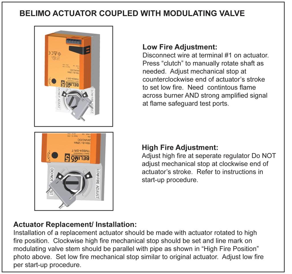
X4 Installation and Operation Manual - POWER FLAME INCORPORATED
 7.13.2 Set the burner s combustion air inlet damper to the approximate setting as shown in this manual for the desired firing rate. Also, verify that the correct main orifice is installed in the main orifice
TROUBLESHOOTING. 1. What is the model and serial number? If you don t know, how old is it? Give description.
 TROUBLESHOOTING There is excellent literature on our website: heatec.com. Look under TEC-NOTE. You will find our newest heater manual. This is full of information (complete with great pictures) on our
Powers TM Controls SW 141 Differential Static Airflow Switches
 Powers TM Controls SW 141 Differential Static Airflow Switches Document No. 155-052P25 SW 1 0518 Description The SW 141 Airflow Switch senses static differential pressure and the diaphragm operated snap
FD68 BURNERS SELECTION GUIDE & ENGINEERING SPECS
 SELECTION GUIDE The following data can be used to fill in the information appropriate for the burner size required: FD68 C A 150 L M BD FORCED DRAFT MODEL 68 FUEL A-OIL ONLY G-GAS ONLY C-GAS/OIL TYPE OF
PAGE 1. TES Operation & Testing Guidelines: Tes Trouble shooting
 PAGE 1 This document outlines questions to ask and components to check during TES troubleshooting. More detailed troubleshooting procedures are available in the TES Troubleshooting Guide. 1. Flow Light
SERVICE MANUAL (INTERNATIONAL)
") SERVICE MANUAL (INTERNATIONAL) IMPINGER CONVEYOR OVEN MODEL 1100-000-A SERIES (SN 2038615 & BELOW) SERVICE MANUAL Lincoln Foodservice Products, LLC 1111 North Hadley Road Fort Wayne, Indiana 46804 United
SERVICE MANUAL (INTERNATIONAL) IMPINGER CONVEYOR OVEN MODEL 1100-000-A SERIES (SN 2038615 & BELOW) SERVICE MANUAL Lincoln Foodservice Products, LLC 1111 North Hadley Road Fort Wayne, Indiana 46804 United
Power Flame Incorporated
 Power Flame Incorporated DC-4 SEQUENCE OVERFIRE DRAFT CONTROL SYSTEM OPERATING AND MAINTENANCE MANUAL THE POWER TO MANAGE ENERGY 2001 South 21 st Street, Parsons, Kansas 67357 Telephone 620-421-0480, Fax
Fan Powered Low Profile Variable Volume Terminal Units
 MANUAL INSTALLATION Fan Powered Low Profile Variable Volume Terminal Units FEVLP / FPVLP / FDVLP Series v001 Issue Date: 07/19/16 07/19/16 Price Industries Limited. All rights reserved. TABLE OF CONTENTS
Product Information Page
 PROGRAMMING GC31 PRESSURE TRANSMITTER TO MONITOR AND CONTROL A HYDRAULIC PRESS PIP #: TR-PI-104 The GC31 differential pressure transmitter is compact, flexible and supports numerous pressure applications
Q35 Series Automatic Vent Damper System
 Installation Sheets Manual 121 Energy Conservation and Miscellaneous Kits Section Q Technical Bulletin Q35 Issue Date 0999 Q35 Series Automatic Vent Damper System Figure 1: Q35 Automatic Vent Damper System
TECHNICAL SERVICE DEPARTMENT Technical Service Bulletin LowNOx Commercial Gas Electronic Spark Ignition Sequence
 The Universal TM gas LowNOx series water heaters contain an electronic spark ignition system. The heater is connected to a 120VAC power source required by the transformer. The transformer steps down the
(For serial numbers before w/ analog control)
") SEQUENCE OF OPERATIONS (For serial numbers before 2038616 w/ analog control) MODEL 1154-000-EA NAT. GAS 230 VAC 50 HZ. 1 PHASE MODEL 1155-000-EA LP GAS 230 VAC 50 HZ. 1 PHASE POWER SUPPLY Electrical power
SEQUENCE OF OPERATIONS (For serial numbers before 2038616 w/ analog control) MODEL 1154-000-EA NAT. GAS 230 VAC 50 HZ. 1 PHASE MODEL 1155-000-EA LP GAS 230 VAC 50 HZ. 1 PHASE POWER SUPPLY Electrical power
E Series CE Approved Intermittent Pilot Ignition Control
 Installation Instructions Issue Date January 11, 2013 E Series CE Approved Intermittent Pilot Ignition Control Application The E Series CE Approved Intermittent Pilot Ignition Control is a safety control
Introduction. System Components
 The Selectra SERIES 94 is for use with either direct or indirect gas fired units (furnaces, ovens, etc.). The system may be field installed on existing equipment or specified for new equipment installation.
Heating and Gas Installations - December 2014
 This is an example of good practice maintenance specifications. It is not exhaustive and should only be used to assist with facilities management or specification of a maintenance contract. Emergency Gas
START-UP CHECKLIST. Date: Job Name: Customer Name: Address: City: State: Zip: Model Number: Serial Number: Qualified Start-up Technician:
 START-UP INSTRUCTION OPTIMUM 36000 To 72000 BTU S PACKAGE UNITS 3 To 6 Ton START-UP CHECKLIST Date: Job Name: Customer Name: Address: City: State: Zip: Model Number: Serial Number: Qualified Start-up Technician:
Troubleshooting Manual
 Troubleshooting Manual NOTICE: DO NOT DISCARD THIS MANUAL Models: LEGACY42-IFT PHOENIX42-IFT 1 TABLE OF CONTENTS A. Normal Operation...3 B. Wiring Diagram...4 C. Troubleshooting IntelliFire Touch...5 D.
CENTRIFUGAL CHILLER. Lubrication System Pull oil sample for spectroscopic analysis.
 CENTRIFUGAL CHILLER Annual Inspection Refrigerant Circuit Check and record refrigerant level Inspect for leak results Calculate refrigerant lass and report to the customer. Repair minor leaks as required
Warm. SDFI Direct Fired Gas Heating System. Sterling. Keeps You. Technical Guide for: Indoor Mounted Units To 64,000 CFM And 9M BTUH
 TGSDFI- SDFI Direct Fired Gas Heating System Technical Guide for: Indoor Mounted Units To 64,000 CFM And 9M BTUH Sterling Keeps You Warm Featuring the Patented AirTrak controlled Air Circulation System
START-UP CHECKLIST. Date: Job Name: Customer Name: Address: City: State: Zip: Model Number: Serial Number: Qualified Start-up Technician:
 START-UP INSTRUCTION START-UP CHECKLIST SERIES 5 36000 To 72000 BTU S PACKAGE UNITS 3 To 6 Ton Date: _ Job Name: Customer Name: Address: City: State: Zip: Model Number: Serial Number: Qualified Start-up
Hamilton 3VO Submittal
 Job RESET FORM Engineer Hamilton 3VO Submittal BOILER s H3H 750 WATER HEATER s H3D 750 Contractor Prepared By Date Input 100% factory fire tested Efficiency: up to 99.8% (based on incoming water) Maximum
Specifications of MAXON VALUPAK burners for 50 Hz operation
 1-1.5-7 Specifications of MAXON VALUPAK burners for 50 Hz operation Capacity data in kw Gross heating value = 10.9 kwh/m 3 (st), d = 0.6. All figures are for balanced - 0 mbar - duct pressure VALUPAK size
First Correlating Revision No. 1-NFPA [ Section No ]
![First Correlating Revision No. 1-NFPA [ Section No ]](/thumbs/73/68781388.jpg "First Correlating Revision No. 1-NFPA [ Section No ]") First Correlating Revision No. 1-NFPA 85-2013 [ Section No. 3.3.52.1 ] 3.3.52.1 Booster Fan. A device fan used to assist in the supply of air to, or the removal of flue gas products from, the combustion
First Correlating Revision No. 1-NFPA 85-2013 [ Section No. 3.3.52.1 ] 3.3.52.1 Booster Fan. A device fan used to assist in the supply of air to, or the removal of flue gas products from, the combustion
SECTION 2.05 FUEL SYSTEM DESCRIPTION FUEL SYSTEM COMPONENTS
 SECTION 2.05 FUEL SYSTEM DESCRIPTION FUEL SYSTEM COMPONENTS The engine fuel system consists of the following engine mounted components: Carburetors Throttle valves Fuel pressure regulator and balance line(s)
ADVANCED PID TROUBLESHOOTING
 ADVANCED PID TROUBLESHOOTING August 29, 2016 A KEY POINT If the drive is telling you something via a Fault, then the problem is probably not the drive. The drive is recognizing a fault and telling you
Quantity Model Length (in.) Width (in.) Height (in.) Volume (CFM) SP (in. wg) 1 Air Curtain Supply (ASP)
 Width (in.) Height (in.) Volume (CFM) SP (in. wg) 1 Air Curtain Supply (ASP)") Mark: ASP 1 Model: ASP - 52.00 - S ASP Air Curtain Supply (ASP) Quantity Model Length (in.) Width (in.) Height (in.) Volume (CFM) SP (in. wg) 1 Air Curtain Supply (ASP) 52 14 10 740 0.13 Supply Collar
Mark: ASP 1 Model: ASP - 52.00 - S ASP Air Curtain Supply (ASP) Quantity Model Length (in.) Width (in.) Height (in.) Volume (CFM) SP (in. wg) 1 Air Curtain Supply (ASP) 52 14 10 740 0.13 Supply Collar
Matrix APAX. 380V-415V 50Hz TECHNICAL REFERENCE MANUAL
 Matrix APAX 380V-415V 50Hz TECHNICAL REFERENCE MANUAL WARNING High Voltage! Only a qualified electrician can carry out the electrical installation of this filter. Quick Reference ❶ Performance Data Pages
SERVICE MANUAL. K Series Gas Kettles 2/3 Jacketed Stationary and Tilting - NOTICE - K40GL Shown
 SERVICE MANUAL K Series Gas Kettles 2/3 Jacketed Stationary and Tilting K20GL K40GL K60GL K20GLT K40GLT K60GLT ML-136090 ML-136091 ML-136092 ML-136094 ML-136095 ML-136096 K40GL Shown - NOTICE - This Manual
Specifications of STICKTITE and PILOTPAK Nozzles
 Low Temperature urners - STICKTITE and PILOTPK Nozzles 1-1.1-5 Specifications of STICKTITE and PILOTPK Nozzles This graph indicates the relationship between capacity and applied mixture differential pressure
Start Up Instructions for the Kiln, Page 1 of 2
 Start Up Instructions for the Kiln, Page 1 of 2 1. Turn the Main Breaker at the right side of the panel on. 2. Press the orange [Control Power On] push button. It will light up when pressed. 3. If the
ZIP Economizer Fault Detection and Diagnostics (FDD) Table
 Table") Fault Detection and Diagnostics (FDD) Table Fault Detection Problem Diagnostic ction (in addition to alarm stored / transmitted) Potential Cause C Fault Code OT sensor predetermined range O damper returns
Fault Detection and Diagnostics (FDD) Table Fault Detection Problem Diagnostic ction (in addition to alarm stored / transmitted) Potential Cause C Fault Code OT sensor predetermined range O damper returns
Installation, Operation and Maintenance Manual
 Document 481038 Model PVF(-H) and PVG Indirect Gas-Fired Heat Modules Indirect Gas-Fired Furnaces Installation, Operation and Maintenance Manual Please read and save these instructions for future reference.
SERVICE MANUAL (INTERNATIONAL)
") SERVICE MANUAL (INTERNATIONAL) IMPINGER CONVEYOR OVENS MODEL 1433-000-E, 1434-000-E, 1456, 1457 WITH PUSH BUTTON CONTROLS Lincoln Foodservice Products, LLC 1111 North Hadley Road Fort Wayne, Indiana 46804
SERVICE MANUAL (INTERNATIONAL) IMPINGER CONVEYOR OVENS MODEL 1433-000-E, 1434-000-E, 1456, 1457 WITH PUSH BUTTON CONTROLS Lincoln Foodservice Products, LLC 1111 North Hadley Road Fort Wayne, Indiana 46804
X100P Load Bank. Read all instructions before using the load bank. Contents
 X100P Load Bank Read all instructions before using the load bank Contents 1. Components... 3 Total Assembly... 3 2) Specifications... 4 a) X100P Load Bank... 4 3) Receiving... 4 4) Safety... 5 a) Grounding...
FABER BURNER ROUTINE MAINTENANCE
 FABER BURNER ROUTINE MAINTENANCE Version 2016 The Faber burner is designed for minimal maintenance; however, the frequency and quantity of maintenance that is required depends upon many factors which vary
Installation, Operation and Maintenance Manual
 Document 481038 Model PVF and PVG Indirect Gas-Fired Heat Modules Indirect Gas-Fired Furnaces Installation, Operation and Maintenance Manual Please read and save these instructions for future reference.
Power Flame Incorporated
 Power Flame Incorporated SUGGESTED SPECIFICATION FOR MODEL HP COMBINATION GAS/OIL BURNERS THE POWER TO MANAGE ENERGY 2001 South 21st Street, Parsons, Kansas 67357 Telephone 316-421-0480, Fax 316-421-0948
To ensure proper installation, digital pictures with contact information to before startup.
 Check List for Optimal Filter Performance [ ] There should be no back-pressure on the flush line. A 1 valve should have a 2 waste line, and 2 valve should have a 3 waste line. Do not use rubber hosing
VALUPAK. Packaged gas burners
 VALUPAK Packaged gas burners 1-1.5-1 E - i - 11/14 High turndown. Available in 6 sizes. Capacities: 0.007 MBtu/hr - 4 MBtu/hr. Stable and clean combustion. Suitable for UV scanner and flame rod. Natural
MOONEY FLOWGRID SLAM SHUT REGULATORS
 MOONEY FLOWGRID SLAM SHUT REGULATORS The Flowgrid Slam Shut Valve is an easy to maintain automatic shutoff device. 2 Dresser Mooney Flowgrid Slam Shut The Slam Shut is designed for use with a pressure
2.0 Burner Operating Parameters and Requirements
 ECLIPSE INFORMATION GUIDE Silicon Carbide Radiant Auto-Recupes Info 322 2/99 WARNING Handle silicon carbide tubes carefully. Do not drop them or hammer on them. Although they feature excellent mechanical
Electric Coil [Make-Up Air / Displacement Ventilation / Space Heating] System
![Electric Coil [Make-Up Air / Displacement Ventilation / Space Heating] System](/thumbs/89/99847795.jpg "Electric Coil [Make-Up Air / Displacement Ventilation / Space Heating] System") V-Series (rev. 08/17/10) Electric Coil [Make-Up Air / Displacement Ventilation / Space Heating] System Note: Optional items and/or items requiring a choice, are shown between brackets and/or parentheses
V-Series (rev. 08/17/10) Electric Coil [Make-Up Air / Displacement Ventilation / Space Heating] System Note: Optional items and/or items requiring a choice, are shown between brackets and/or parentheses
The IAQ50 Air Damper/Monitor Installation and Maintenance Manual
 The IAQ50 Air Damper/Monitor Installation and Maintenance Manual RUSKIN MANUFACTURING 3900 Dr. Greaves Road Kansas City, Missouri 64030-1183 U.S.A. ! WARNING DO NOT TAMPER WITH (REMOVE, REPLACE, RELOCATE
LANDFILL GAS ELEVATED (CANDLESTICK) FLARE SYSTEM
 FLARE SYSTEM") LANDFILL GAS ELEVATED (CANDLESTICK) FLARE SYSTEM Part 1. General 1.01 Description A. This section describes a candlestick flare system for the combustion of landfill gases. The flare system must be of
LANDFILL GAS ELEVATED (CANDLESTICK) FLARE SYSTEM Part 1. General 1.01 Description A. This section describes a candlestick flare system for the combustion of landfill gases. The flare system must be of
Field proven low emissions. State-of-the-art low NOx firing - adjustable for application flexibility
 -.9- KINEDIZER LE High capacity low NOx gas burners Field proven low emissions. State-of-the-art low NOx firing - adjustable for application flexibility Lower NOx and less excess air than standard KINEDIZER
Design and Application Details
 Model 400 OVENPAK Gas Page 2105 Design and Application Details OVENPAK s are nozzle-mixing gas burners for many industrial direct-fired applications where clean combustion and high turndown are required.
High Frequency SineWave Guardian TM
 High Frequency SineWave Guardian TM 380V 480V INSTALLATION GUIDE FORM: SHF-IG-E REL. January 2018 REV. 002 2018 MTE Corporation High Voltage! Only a qualified electrician can carry out the electrical installation
BMF TROUBLESHOOTING GUIDE
 BMF TROUBLESHOOTING GUIDE This document contains troubleshooting guidelines for PEP's standard BMF filters with pumps. REFERENCE DOCUMENTS: W-X-0039 BMF Electrical Wiring Drawing WP0011 BMF Control Panel
Specifications of STICKTITE and PILOTPAK Nozzles
 -.-5 Specifications of STICKTITE and PILOTPK Nozzles This graph indicates the relationship between capacity and applied mixture differential pressure for STICKTITE and PILOTPK nozzles when fed with an
ESC2301. Universal Electronic Governor Controller Operation Manual
 ESC2301 Universal Electronic Governor Controller Operation Manual *Replaces most Woodward, Barber Colman & Cummins Speed Controls Features Smoke Limit Control, Idle Speed Control, 12V or 24V input Suitable
 POWER EXHAUST START UP PRE START UP ONCE THE POWER EXHAUST ECONOMIZER IS INSTALLED, REMOVE THE ACCESS DOORS ON THE EXHAUST CABINET. ROUTE LINE VOLTAGE CABLE FROM THE VFD TO THE DISCONNECT OR UNIT POWER
Info 110 4/98. RatioMatic Burners. RM Series version through 600 Sizes. 750 through 2000 Sizes
 Info 110 4/98 RatioMatic Burners RM Series version 1.01 50 through 600 Sizes 750 through 2000 Sizes For Ratiomatic Serial Numbers 95-5500 and Above Version 1.01 7/97 Contents 1.0 Operating Parameters &
XID ENHANCEMENT SYSTEM IMPROVED EFFICIENCY AND PERFORMANCE
 IMMERSION FIRED HOT WATER BOILER April 1, 2003 GENERAL DESCRIPTION The Sellers immersion fired hot water boiler is a horizontal, single pass, firetube boiler designed to burn natural gas. The unique burner
Hayward error codes and troubleshooting
 http://waterheatertimer.org/intermatic-trippers-and-parts.html#pool 50 Hayward error codes and troubleshooting Section V. TROUBLESHOOTING http://www.hayward-pool.com/prd/in-ground-pool-manuals_10201_10551_14502_-1
NECO Pumping Systems
 INSTALLATION OPERATION & MAINTENANCE INSTRUCTIONS For Your NECO Pumping Systems PACKAGED CIRCULATING SYSTEM THIS COMPLETELY ASSEMBLED, TESTED, PACKAGED CIRCULATING SYSTEM IS OF THE HIGHEST QUALITY AND
Terms. Direct Acting (DA) The action of a controller that increases its branch line pressure as the controlled variable increases
 The action of a controller that increases its branch line pressure as the controlled variable increases") Pneumatic Control Terms Direct Acting (DA) The action of a controller that increases its branch line pressure as the controlled variable increases Terms Reverse Acting (RA) The action of a controller that
Pneumatic Control Terms Direct Acting (DA) The action of a controller that increases its branch line pressure as the controlled variable increases Terms Reverse Acting (RA) The action of a controller that
Installation Manual. Mixing Box Control Systems Installation, Operation, and Maintenance Manual. 605 Shiloh Road Plano, Texas
 Installation Manual IOM-MBC-00 08-30-04 Mixing Box Control Systems Installation,, and Maintenance Manual Contents Page Introduction...1 General...1 Safety...1 Inspection...1 Mixing Box Control Systems...2
ICEMINI & Vertical MTI Units
 ICEMINI & Vertical MTI Units ICEMINI Units......K-1 ICEMINI-8MPN (Dimension Information)....... K-2 ICEMINI-8MPN (Horizontal Small)....... K-3 ICEMINI-8MPN (Vertical Small)........ K-4 ICEMINI-8MPN (Vertical
SD Bendix ET-2 Electronic Treadle DESCRIPTION OPERATION
 SD-15-4106 Bendix ET-2 Electronic Treadle PIVOT SPRING MOUNTING BASE DESCRIPTION CONNECTOR FIGURE 1 - ET-2 ELECTRONIC TREADLE ROLLER TREADLE COVER DOUBLE RETURN SPRING CABLE ASSEMBLY The ET-2 is an electronic
INSTALLATION INSTRUCTIONS COMMERCIAL ROOM VENTILATORS WITH EXHAUST. For Use with Bard 2 2-1/2 Ton Wall Mount T Series Heat Pumps
 INSTALLATION INSTRUCTIONS COMMERCIAL ROOM VENTILATORS WITH EXHAUST MODELS CRVMWH-3 For Use with Bard 2 2-1/2 Ton Wall Mount T Series Heat Pumps Bard Manufacturing Company, Inc. Bryan, Ohio 43506 Since
REFERENCE MANUAL FORM: MX-TRM-E REL REV MTE
 Matrix APAX 380V-415V 50Hz TECHNICAL REFERENCE MANUAL FORM: MX-TRM-E REL. September 2014 REV. 002 2014 MTE Corporation WARNING High Voltage! Only a qualified electrician can carry out the electrical installation
SEASONAL MAINTENANCE CHECKLISTS Johnson Controls
 SPRING CHECK LIST ABSORPTION CHILLERS Check starter and control panel. Leak test. Check hand valve diaphragms and replace as required. Check operation of purge unit. Change oil in the purge pump. Lubricate
ECONOMIZERS. 5/2012 Supersedes
 Litho U.S.A. 2012 ECONOMIZERS 507031 01 5/2012 Supersedes 506747 01 K1ECON ECONOMIZERS INSTALLATION INSTRUCTIONS FOR ECONOMIZERS AND OUTDOOR AIR HOODS USED WITH KG/KC/KH 024, 030, 036, 048, 060, 072, 090
Circuit Board Diagnostics
 Circuit Board Diagnostics NOTE: Discharge your body s static electricity before touching unit. An electrostatic discharge can adversely affect electrical components. Troubleshoot Integrated Control Module
Constant Voltage/Constant Current Test System
 Description Constant Voltage/Constant Current Test System The Constant Voltage/Current Test System may be used for constant voltage or constant current pulse testing of automotive and aerospace igniters,
SECTION 3.00 WARNING WARNING ENGINE STARTUP AND SHUTDOWN PRESTART INSPECTION
 SECTION 3.00 ENGINE STARTUP AND SHUTDOWN PRESTART INSPECTION Be sure that the clutch, circuit breaker, or other main power transmission device is disconnected. Generators develop voltage as soon as the
36H Gas Control Product Information
 Single Stage 36H Two Stage 36H 36H Gas Control Product Information The 36H combination gas control valve is a versatile multifunction control designed to meet the requirements for use with intermittent
Series 20 Installation Instructions
 Series 20 Installation Instructions Installation Instructions and field service checklist Read these instructions carefully. Failure to follow them could result in a fire or explosion causing property
Installation. Check, Test & Start Procedure
 Installation General CAUTION: Sheet metal parts, screws, clips and similar items inherently have sharp edges, and it is necessary that the installer and service personnel exercise caution. The installation
G76x Direct Spark Ignition Controls
 Installation Sheets Manual 121 Gas Combustion Combination Controls and Systems Section G Technical Bulletin G76x Issue Date 0400 G76x Direct Spark Ignition Controls Figure 1: G76x Direct Spark Ignition
ESCONDIDO FIRE DEPT TRAINING MANUAL Section DRIVER OPERATOR Page 1 of 13 Pumps and Accessory Equipment Revised
 DRIVER OPERATOR Page 1 of 13 PUMPS AND ACCESSORY EQUIPMENT Pumps are designed for many different purposes. In order to understand the proper application and operation of a pump in a given situation, firefighters
CCS Zone/Bypass Damper Assembly
 Code No. LIT-1900539 Issued July 15, 2011 UZR-xx-x, UBR-xx-x, UZD-0xxX0xx-x, UBD-0xxX0xx-x CCS Zone/Bypass Damper Assembly Description The Commercial Comfort System (CCS) Zone/Bypass Damper are zone control
Electric Furnace KF/KFS Series
 Electric Furnace KF/KFS Series KF/KFS 20 20 1 A B C D A: Series B: 20-208V 24-240V 48-480V C: Kilowatts D: 1 or 3-phase Heavy duty open-coil element Direct drive motor Up to 3-speed motor Standard 24 Volt
SineWave Guardian TM 380V 600V INSTALLATION GUIDE. Quick Reference. ❶ How to Install Pages 6 17 ❷ Startup/Troubleshooting Pages WARNING
 SineWave Guardian TM 380V 600V INSTALLATION GUIDE FORM: SWG-IG-E REL. October 2018 REV. 003 2018 MTE Corporation High Voltage! Only a qualified electrician can carry out the electrical installation of
G600 Series Replacement Intermittent Pilot Ignition Controls
 Installation Instructions G600 Issue Date 0601 G600 Series ment Intermittent Pilot Ignition Controls Installation IMPORTANT: These instructions are intended as a guide for qualified personnel installing
KG7T (C and L Series)
") TECHNICAL SPECIFICATIONS KG7T (C and L Series) Two Stage, Fixed Speed ECM, Condensing Upflow/Horizontal and Downflow Gas Furnaces Induced Draft - 95.1 AFUE Input 60,000-120,000 Btuh The high efficiency
TECHNICAL SPECIFICATIONS KG7T (C and L Series) Two Stage, Fixed Speed ECM, Condensing Upflow/Horizontal and Downflow Gas Furnaces Induced Draft - 95.1 AFUE Input 60,000-120,000 Btuh The high efficiency
FOR USE IN SOLUTION AIR HANDLING UNITS
 AMS-60 AIRFLOW MONITORING DEVICE APPLICATION GUIDE Supersedes: NOTHING Form 102.20-AG1 (303) FOR USE IN SOLUTION AIR HANDLING UNITS GENERAL The YORK AMS-60 is an airflow monitoring device which combines
ULTRA-ZONE FORCED AIR ZONE CONTROLS EWC
 INDEX DAMPERS MOTORIZED MODEL RSD ROUND... 7-5 MODEL URD ROUND... 7-5 ND SERIES... 7-6 7-7 STATIC PRESSURE CONTROL MODEL EBD RECTANGULAR... 7-7 MODEL EBD ROUND... 7-7 MODEL PRD... 7-8 MODEL PRD-RD... 7-8
G861 Series Integrated Function. Direct Spark Ignition Control
 Installation Sheets Manual 121 Gas Combustion Combination Controls and Systems Section G Technical Bulletin G861 Issue Date 0699 G861 Series Integrated Function Direct Spark Ignition Control Figure 1:
MANUAL INSTALLATION. Venturi FX. VFX Series. v100 Issue Date: 11/22/ Price Industries Limited. All rights reserved.
 MANUAL INSTALLATION Venturi FX VFX Series v100 Issue Date: 11/22/16 2016 Price Industries Limited. All rights reserved. TABLE OF CONTENTS Product Overview Safety Precautions... 1 Caution to Contractors...1
5. Alignment and Adjustments
 5. Alignment and Adjustments PRECAUTION 1. High voltage is present at the high voltage terminals during any cook cycle. 2. It is neither necessary nor advisable to attempt measurement of the high voltage.
KG7T (C and L Series)
") TECHNICAL SPECIFICATIONS KG7T (C and L Series) Two Stage, Fixed Speed ECM, Condensing Upflow/Horizontal and Downflow Gas Furnaces Induced Draft - 95.1 AFUE Input 60,000-120,000 Btuh The high efficiency
TECHNICAL SPECIFICATIONS KG7T (C and L Series) Two Stage, Fixed Speed ECM, Condensing Upflow/Horizontal and Downflow Gas Furnaces Induced Draft - 95.1 AFUE Input 60,000-120,000 Btuh The high efficiency
Part List: Jandy LXI Series Heaters
 Part List: Jandy LXI Series Heaters Models LXI250, LXI400 For pool heater parts, equipment and any pool accessories, visit www.torontopoolsupplies.ca 1-844-416-7665 416-623-9334 info@torontopoolsupplies.ca
Applies to: Indoor or Outdoor, Gas, Direct-Fired, Makeup Air/Heating Systems Model RDF and Models ADF/ADFH
 Form O-ADF/RDF (12-15) Obsoletes O-ADF/RDF (Version A.1) Operation / Maintenance / Service Applies to: Indoor or Outdoor, Gas, Direct-Fired, Makeup Air/Heating Systems Model RDF and Models ADF/ADFH Model
EG3000. Generator Electronic Governor Controller Operation Manual
 EG3000 Generator Electronic Governor Controller Operation Manual Smoke Limit Control, Idle Speed Control, suitable for Builtin, Non-Built-in and PT Pump Type Actuator. SP POWERWORLD LTD Willows, Waterside,
NSGV PT-1000 PORTABLE WELDING STATION I, O & M MANUAL
 APPLICATION OF DUST CONTROL EQUIPMENT: CAUTION - Warning Improper operation of dust control system may contribute to conditions in the work area or facility that could result in severe personal injury
TGIF-3. Indirect Fired Heating Systems. Technical Guide for: IF Indoor Installations. IFW Outdoor Installations. Applied Air. Keeps You.
 TGIF-3 Indirect Fired Heating Systems Technical Guide for: IF Indoor Installations IFW Outdoor Installations Applied Air Keeps You Warm Indirect Fired Heating Systems Technical Guide In the business of
Heater Troubleshooting Guides
 Heater Troubleshooting Guides Table Of Contents LRZE, 3 LRZM.. 4, 5 LXi.. 6, 7 LITE LD.. 8, 9 LITE LJ.. 10, 11 LITE LG. 1, 13 LX or LT STANDARD BURNERS 14, 15 LX or LT LOW x BURNERS. 16, 17 HiE 18, 19
GAS BURNERS TYPE JR Forced Draft Burners 3450 RPM motor and squirrel cage blower Leakage test, pilot and main gas cocks Gas electric pilot and gas ign
 3450 RPM Motor, squirrel cage blower, panel with 2 lights (power and main fuel) and control switch Gas electric pilot and gas ignition transformer Leakage test cock, pilot cock and main gas cock Pilot
PGMD Series 10 SEER. International Comfort Products 651 Heil Quaker Avenue Lewisburg, Tn Part No
 PGMD Series 10 SEER PACKAGE COOLING 1-1/2THRU5TONSINGLEPHASE CONVERTIBLE SINGLE PACKAGE GAS/ELECTRIC UNIT SINGLE PACKAGE Efficiency: PGAA - 10 SEER. Combination gas heating and electric cooling, self-contained
MODEL 10LH SPECIFICATION
 MODEL 10LH SPECIFICATION 1.0 General Specifications There will be furnished one (1) only Grind Hog TM Model 10LH Comminutor as manufactured by G.E.T. Industries, Inc. Rotation shall be in a clockwise (standard)
LEAD FREE * LFF113RFP Flood Protection Shut Down Valve
 Technical Bulletin TB-ACV-LFF11RFP LEAD FREE * LFF11RFP Flood Protection Shut Down Valve Installed upstream of Reduced Zone Backflow Preventer. Normally Open Valve - Closes when continuous discharge from
Powers TM Controls EA 338 Electronic Actuator
 Powers TM Controls Technical Instructions Document No. 155-136P25 EA 338-1 Description Features 24 Vac power supply. The s are used with floor mount linkage kits to operate dampers in HVAC installations.
INSTALLATION INSTRUCTIONS COMMERCIAL ROOM VENTILATORS WITH EXHAUST. For Use with Bard CH Series 3, 4, & 5 Ton Wall Mount Heat Pumps
 INSTALLATION INSTRUCTIONS COMMERCIAL ROOM VENTILATORS WITH EXHAUST MODEL CHCRV-5 For Use with Bard CH Series 3, 4, & 5 Ton Wall Mount Heat Pumps Bard Manufacturing Company, Inc. Bryan, Ohio 43506 Since
North American Automatic Manual Reset and Motorized Valves
 Combustion North American Automatic Manual Reset and Motorized Valves 1516 Manual Reset 1517 Motorized 1516/1517 Automatic Oil Shutoff Valves Agency approvals: UL, FM, CSA Proof-of-Closure Switch High
Air Pressure Sensing Switch with Adjustable Set Point Range. Dimensions in Inches (Millimeters)
") Cleveland Controls Division of UniControl Inc. Model AFS 222 Air Pressure Sensing Switch with Adjustable Set Point Range Application The Model AFS-222 is a general purpose proving switch designed for HVAC
Cleveland Controls Division of UniControl Inc. Model AFS 222 Air Pressure Sensing Switch with Adjustable Set Point Range Application The Model AFS-222 is a general purpose proving switch designed for HVAC
Distributed By: M&M Control Service, Inc PRODUCT PRODUCT CODE TECHNICAL INSTRUCTIONS PAGE #
 PRODUCT PRODUCT CODE TECHNICAL INSTRUCTIONS PAGE # Switches Selector Switches SW 786 155-118P25 G-3 Positioning Switch SW 141 155-117P25 G-5 Enthalpy Control Switch EE 141 155-054P25 G-7 Static Pressure
XS400 Load Bank. Read all instructions before using the load bank. Contents
 Read all instructions before using the load bank Contents 1) Components... 3 Total Assembly... 3 2) Specifications... 4 3) Receiving... 4 4) Safety... 5 a) Grounding cam... 6 b) Power connections... 6