HS Refrigeration Screw Compressor Troubleshooting Guidelines. SG March 2014
|
|
|
- Silvester McCoy
- 6 years ago
- Views:
Transcription


1 HS Refrigeration Screw Compressor Troubleshooting Guidelines SG March 2014


2 Refrigeration Screw Compressor Troubleshooting Guidelines SG March 2014 BITZER Screw Compressors CS High Temp Series Troubleshooting Guidelines The intention of this document is to serve as general guidelines. The information contained is not intended to replace specific equipment and/or system manufacturer's information or guidelines. BITZER implies no liability for the information contained. It is BITZER's implicit intention that nothing contained in this guide replaces any past, present or future warranty policy of BITZER and/or any other manufacturer's equipment These guidelines are supplied as a recommended procedure for troubleshooting the CS screw compressor These guidelines are not a replacement for information specific to that of the manufacturer or the manufacturer's system technical product information. Each system may vary in design, usage and specifications. This document is intended for use specific to the compressor only and not intended to be a "catch all" for any and every possible application of the compressor. BITZER's intention is that only qualified and certified (where applicable) individuals specific to the refrigeration industry use the information contained and all standard refrigeration handling and safety practices must be followed at all times. BITZER's intention is that all electric work is performed by qualified and certified (where applicable) individuals and all standard electrical safety practices must be followed at all times. 1
3 Contents Section 1: General Information Additional information can be found in the following publications: Modules: Oil Type Requirements / Approved Oils: Nameplate Voltages: Additional Oil Cooling via Liquid Injection:... 4 Section 2: Commissioning General Information and Recommendations: Electrical Connection: Check for Correct Direction of Rotation:... 5 Section 3: HS Screw Compressor Operating Parameters Recommended Checks: Operating Guidelines: HS Screw Compressor Cycling Rates or Starts per Hour:... 7 Section 4: General Maintenance and Repair Oil Supply: Integrated Discharge Check Valve: Oil Filter: Safety Devices:... 7 Section 5: Troubleshooting Recommendations Compressor Will not Start or Run: Compressor Start and Shuts Off Compressor Starts and Shutsdown within 2-3 seconds: Compressor starts, runs more than 2-3 seconds and then shuts down: Compressor Starts but Trips Repeatedly on Overload or Breaker Protection Devices: Troubleshooting the SE-E1 /SE-E2 Module Checking the Motor Winding Sensors: Checking the Discharge Gas Temperature Sensor with SE-E1: Checking Power Supply to the SE-E1 Module Power:
4 5.4 Compressor Runs with Problem Low Discharge Temperature: During Shutdown, the Compressor Spins in Reverse: Compressor is Noisy during Start-up and Returns to Normal: Compressor will not Refrigerate: Miscellaneous Troubleshooting Oil Flow: Flooded Compressor: Subcooler Adjustments: Compressor will not Load or Un-load: HS53 compressors: the below steps will assist in troubleshooting the capacity control: HS Compressors: HS85 Compressors: Section 6: Terminal Box Wiring Diagrams Section 7: ESC200 Electronic Modules (HS53-64 and 74 Compressors) Section 8: ESC201 Electronic Modules (HS53-64 and 74 Compressors) Appendix A: Screw Compressor Measurements Data
5 Section 1: General Information 1.1 Additional information can be found in the following publications: SH-100 Application Guidelines HS53-3, HS64, HS74 SH-110 Application Guidelines HS85 SB-100 Operating Instructions HS53-3, HS64, HS74 SB-110 Operating Instructions HS85 ST-122 SE-E2 Electronic Module Technical Information ST-600 Piping Recommendations TB-008 Control Modules and Application Kits TB-0025 Oil Separators TB-0035 Replacing the Discharge Check Valve in BITZER Screw Compressors ESC200 Electronic Module Guidelines ESC201 Electronic Module Guidelines 1.2 Modules: The BITZER HS Screw compressors utilize an Electronic Module of 2 types. Standard SE-E1 Electronic modules are 110/220 dual voltage. The SE-E1 module provides the following protection: Motor winding temperature, Discharge gas temperature, Direction of rotation / Phase sequence, Cable break in the PTC sensor circuit, High amp draw, Inconsistent / Incorrect power supply to the module. Optional ESC201 Electronic module used with the HS compressors. Obsolete ESC200 Electronic module used prior to Oil Type Requirements / Approved Oils: BITZER HS Screw Compressor Oils: Check the oil type to ensure the proper oil is used per the refrigerant type. R22 = B100 or B150SH oil only. R134A, R407C, R507A, R407A, R407F and R404A = BSE170 only. 1.4 Nameplate Voltages: 2NU (HS53): /3/60. Operating range: 187 to 253 vac. 2NU (HS53): 460/3/60. Operating range: 414 to 506 vac. 2PU (HS ): 208/230/3/60. Operating range: 187 to 253 vac. 4PU (HS ): 460/3/60. Operating range: 414 to 506 vac. 5PU (HS ): 575/3/60. Operating range: 517 to 633 vac. 1.5 Additional Oil Cooling via Liquid Injection: Depending on the refrigerant being used, if the discharge gas temperature exceeds 190 F (88 C), additional liquid injection oil cooling should be used. Note: Liquid injection oil cooling must be limited to 10% maximum of the capacity of the compressor at the operating parameters. 4
6 Section 2: Commissioning 2.1 General Information and Recommendations: Terminal lug nuts and bolts: After shipping, installation and prior to initial start-up, all terminal bolts and nuts should be checked for tightness. Ensure all safety switches are in their proper positions. All system and compressor safety features/devices have been checked and verified to be in correct operational positions. Check High and Low pressure switches and ensure they have been adjusted. Check all wiring connections inside of the terminal box. Visual safety checks of the compressor and system. Oil level in the oil separator should be visible in the sight glass. Crankcase heater should be energized hours prior to initial start and the oil temperature measured at the bottom should F above ambient. For part winding start systems, ensure that PW1 and PW2 are phased correctly. Ensure the jumper wires are installed on 6-7, 5-9 and 4-8 for 230 volt systems. Check the switch over timing from PW1 to PW2. The maximum switch over time should be.5 to a maximum of 1 second. 2.2 Electrical Connection: Also see Appendix A for wiring examples. For 9 lead motors on HS53 series compressors: For Part Winding Starting: For part winding start systems, ensure that PW1 and PW2 are phased correctly. Ensure the jumper wires are installed on 6-7, 5-9 and 4-8 for 230 volt systems. Check the switch over timing from PW1 to PW2. The maximum switch over time should be.5 to a maximum of 1 second. For Direct on Line Starting: 230 Volt Set-up: Ensure the jumper wires are installed on 6-7, 5-9 and 4-8 with the jumper bars installed over 3-9, 2-8 and Volt Set-up: Ensure jumper bars are installed over 6-9, 5-8 and 4-7. Always check and verify wiring schematics. For 6 Lead motors on HS64, 74 and 85 series compressors: For Part Winding Starting: Ensure that PW1 and PW2 are phased correctly. For Direct on Line Starting: Ensure jumper bars are installed over 1-7, 2-8 and 3-9. Always check and verify wiring schematics. 2.3 Check for Correct Direction of Rotation: Screw compressors can only be operated in one direction of rotation; otherwise, substantial mechanical damage can occur. Connect a compound gauge to the suction service valve and ensure the port is open with the service valve almost closed. Bump start the compressor for approximately.5 to 1 second maximum. If the direction of rotation is correct the suction pressure will drop immediately. 5
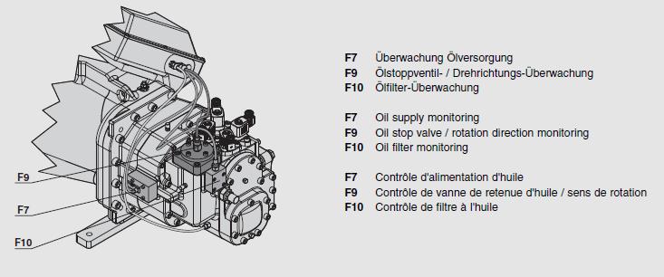
7 A rise in suction pressure or a cut-out of the electronic module will indicate a wrong direction of rotation. If this happens, change over two of the electrical phases at the terminals of the common supply line and check rotation again. After rotation is verified and correct, slowly open the suction service valve. Section 3: HS Screw Compressor Operating Parameters 3.1 Recommended Checks: The items listed below are a minimum recommendation of the values and data that should be recorded during and after start-up. Also see form number CF-0017 Screw Compressor Test Measurements Form. Oil Level Check: The oil should be visible in the oil separator sight glass at all times when the compressor/s is in operation. The level can vary slightly in the sight glass as the compressors are staged, loaded and/or unloaded. Setting the High and Low pressure controls: These devices should be set in accordance with the application limits. They should be set based on specific system operating parameters. Check Operating Data: SST and Suction Temperature. SCT and Suction Superheat. ECO and ECO Suction Superheat. ECO Pressure. Discharge Gas Temperature. Oil Temperature (taken at the inlet of each compressor). Current and Voltage. Setting of the Condenser Pressure Control: The setting must be made so that a minimum pressure differential of a least 70 psi is reached between suction and discharge 20 seconds after start. Refrigerant Charging: Adding refrigerant after the initial charging has been completed: For topping off purposes, the vapor style of charging is preferred. If liquid refrigerant is charged, short periods of charging are acceptable providing the superheat values are maintained and the oil level is monitored to prevent foaming. 3.2 Operating Guidelines: Max discharge line temperature (outside) = 212 F. Min discharge line temperature (outside): = / > 35 F above the condensing temperature = / < 35 F above the condensing temperature (ESC201 function) Critical discharge line temperature (outside) = 200 F (ESC201 function) Max oil temperature from cooler = 100 F. Min suction superheat = 5 F. Maximum suction superheat = 35 F*. Typical suction superheat = F. Minimum pressure differential between suction and discharge = 70 psi Max oil pressure differential across the oil filter = 25 psi (alarm signal). Max motor temperature = 212 F. Reverse rotation pressure switch: 30psi cut-in / 20psi cutout. 6
8 3.3 HS Screw Compressor Cycling Rates or Starts per Hour: The recommended maximum cycles or starts per hour for the HS53, 64 and 74 series compressors is 7 starts per hour with a minimum on time of 5 minutes. The recommended maximum cycles or starts per hour for the HS85 series compressors are 4 starts per hour with a minimum on time of 5 minutes. Section 4: General Maintenance and Repair BITZER Refrigeration screw compressors do not have any internal valves and therefore are relatively maintenance free. However, the following points should be checked as a planned maintenance: 4.1 Oil Supply: Annual oil checks and even oil analysis is recommended. If it becomes necessary to add or change oil, care must be taken because the oils used are very hygroscopic and should not remain open to the atmosphere for long periods of time. 4.2 Integrated Discharge Check Valve: Each screw compressor has an internal discharge check valve located under the discharge service valve. After shutdown, the compressor will spin backwards for a short period of time until the pressures equalize. If the check valve becomes dirty or faulty, the length of reverse rotation at shutdown will increase and the valve must be inspected and/or replaced. Further information can be found in TB-0035 Replacing the Discharge Check Valve. 4.3 Oil Filter: Each screw compressor has a 10 micron oil filter. This filter is recommended to be replaced on a yearly basis. HS53, 64 and 74 series screw compressors have external oil filters. HS85 series screw compressors have accessible internal oil filters. On new systems days of operation, the filter element should be replaced with a new element. 4.4 Safety Devices: The screw compressors have an installed electronic module which requires no maintenance, although each connection should be checked for tightness. All safety devices including the low and high pressure cutout switches should be checked as per the manufacturer s recommendations. Section 5: Troubleshooting Recommendations Before attempting any electrical troubleshooting, make sure all grounds are connected and secure and there is continuity throughout the compressor system. Also ensure the compressor system is correctly grounded to the power supply. Only qualified service personnel familiar with electrical and mechanical troubleshooting techniques should evaluate the compressor and/or system. 7


9 5.1 Compressor Will not Start or Run: If a compressor fails to start and run properly, it is important that the compressor be checked to determine its condition. It is possible that "external electrical components" are defective, the module has tripped, a safety device has tripped or other conditions may be preventing the compressor from starting. If the compressor is not the source of the problem, replacing the compressor will only result in the unnecessary expenditure of time and money while the original problem still exists. If there is no voltage at the compressor terminals, follow the attached wiring diagram and/or systems blueprints and check back from the compressor to the power supply to find where the circuit is interrupted. Check all controls (low pressure, high pressure, thermostats, etc) to see if the contact points are closed. Check all contacts. Check all fuses to ensure one is not blown. Check disconnects. If voltage is available at the compressor terminals and the voltage is lower than 90% of rated voltage listed on the compressor nameplate, it is possible the motor may not have enough starting torque. Check to determine proper wire sizes are adequate, all electrical connections are tight, the circuit is not overloaded and/or the power supply is adequate. Check the electronic module inside the terminal box for proper connections per the wiring diagrams. If a "like" module is available, try changing the modules and see if the problem persists. 5.2 Compressor Start and Shuts Off Compressor Starts and Shutsdown within 2-3 seconds: If the compressor has a mechanical reverse rotation switch, check all wiring. These switches require a vibration damper. The damper may be faulty which resulted in a failed switch. Two different types of vibration dampers have been used, brass and/or steel. When replacing a reverse rotation switch, the damper should also be replaced. The replacement kit is part number During startup, the switch will close with a 30psi pressure rise Compressor starts, runs more than 2-3 seconds and then shuts down: If the compressor starts and shuts down after a normal fault due to temperature, each module has a general alarm output which can be checked across the terminals 11 and 12. The trip point >11.5 kohms and resets <2.95 kohms. The motor winding temperature and discharge gas temperature trip is >212 F. The most common cause of excessive or high motor temperatures are due to high superheat values at the compressor suction >20 F, low refrigerant charges, un-balanced voltages, excessive reduced loads with no additional cooling, contaminants in the refrigerant charge and/or excessive start-stops (short cycling). If the compressor tripped due to the discharge gas temperature sensor, the most common cause is due to high superheat / return gas temp values at the compressor suction, frequent start-stops (short cycling), excessive reduced loads with no additional cooling, operation outside of the approved window for the refrigerant used, low or lack of oil, poor oil quality and low refrigerant charge Compressor Starts but Trips Repeatedly on Overload or Breaker Protection Devices: Check the compressor suction and discharge pressures while the compressor is operating. Be sure the refrigerant is compatible with the compressor and the temperature range is within the limitations of the 8
10 compressor. If pressures are excessive, check the condenser, remove non-condensables from the system, check / modify the system controls or take other action as may be necessary to avoid excessive operating pressures. An excessively low suction pressure may indicate a loss of charge. The compressor motors are refrigerant cooled and may not be getting enough cooling across the motor. Low evaporator loads may also result in low suction pressures. Most systems will have pressure ports to aid in checking system pressures. Excessive temperatures on the suction and discharge lines may also indicate abnormal operating conditions. Check the line voltage at the motor terminals while the compressor is running. The voltage should be within 10% of the nameplate voltage rating. If outside these limits, the voltage supply must be brought within the acceptable range or a compressor with different electrical characteristics may have to be used. Check the amperage while the compressor is in operation on each line. The value should be within 10% of the published data for the operating conditions taken while operating. High amperage can be caused by low voltage, high discharge pressure, high suction pressure, high oil levels and/or possible abnormal wear internally. Check amperage on all 3 or 6 legs depending on application (DOL or PWS). One or two high amperage legs can cause an unbalanced motor which can lead the motor to overheat. If all three legs are not drawing approximately equal amperage, temporarily switch the leads to the motor to determine if the high leg stays with the line or stays with the terminal. If the high amperage reading stays with the line, the problem is in the line voltage power supply and not the compressor. If the high amperage reading stays with the terminal, the problem may be with the motor. If the amperage is sufficiently unbalanced to cause the module to trip >10% and the voltage supply is unbalanced, check with the power company to remedy a solution to correct the problem. Check all wiring as per the wiring diagram in the terminal box and/or the system diagrams. Ensure that Jumper Bars should be used (direct on line starting) or not to be used for PWS (part winding start) systems. Ensure they are tight, if used. 5.3 Troubleshooting the SE-E1 /SE-E2 Module Checking the Motor Winding Sensors: After ensuring all power is turned off to the compressor, Un-plug M-1 and M-2 or T-1 and T-2 (depending on compressor) spade connectors from the terminal plate. Normal resistance values will be ohms across these terminals at 95 F ambient temperature Checking the Discharge Gas Temperature Sensor with SE-E1: After ensuring all power is turned off to the compressor, disconnect the sensor by removing the brown and blue wires from the input connections. Normal resistance values at ambient temperatures (95 F) will ohms Checking Power Supply to the SE-E1 Module Power: Check to ensure the proper module power voltage is being used. The standard modules are 110/220 dual voltage. Ensure power is connected to L and N. 5.4 Compressor Runs with Problem Low Discharge Temperature: Low discharge gas temperature can result from very low superheat settings which causes liquid refrigerant to be introduced through-out the compression cycle. This leads to premature bearing wear as the liquid displaces the oil. 9
11 Excessive foaming in the oil separator sight glass is another symptom of low superheat settings. The compressor suction superheat values must be checked at both minimum and maximum capacity and adjusted to maintain no lower than 5 F During Shutdown, the Compressor Spins in Reverse: Each compressor has an internal discharge check valve. This valve prevents refrigerant from entering the compressor through the discharge during shutdown and/or idle conditions. When the compressor shuts down, normal reverse spinning of the rotors is normal as there are no valves similar to a recip compressor. This occurs seconds. The compressor s pressure will equalize whenever the compressor is shutdown or cycles off. The sound of the pressures equalization will be longer in duration. Whenever the rotors spin backwards longer than 5 seconds, the discharge check valve may be dirty, worn or possibly faulty and must be inspected and/or replaced. See Technical Bulletin TB-0035 for complete details Compressor is Noisy during Start-up and Returns to Normal: This is an indication of liquid refrigerant remaining in the compressor after shutdown, liquid refrigerant returning to the compressor during off cycles which will lead to a flooded start condition. Determine the source of refrigerant entering the compressor. Possible checks should include the expansion and/or solenoid valve not closing at shutdown. If the compressor has liquid injection oil cooling and depending on the type of valve used, if the compressor was injecting at normal shutdown and if the liquid supply solenoid valve is faulty or does not close. Liquid will continue to be injected into the compressor through the economizer port. If liquid injection oil cooling is used, a solenoid valve must be used. If the compressor has utilizing an economizer circuit, ensure the solenoid valve is operating properly and not leaking or closing when the compressor is idle. Another symptom if liquid refrigerant is present in the compressor is possible tripping on the motor overloads due to continuous locked rotor current Compressor will not Refrigerate: Check the refrigerant charge and operating pressures. Any abnormal operating conditions must be corrected. If the suction pressure is high and the evaporator and condenser are functioning normally, check the compressor amperage draw. An amperage draw within 5% of published rating data, corrected for actual measure voltage, indicates normal compressor operation. An amperage draw considerably above published rating data for the given operating pressures indicates possible internal damage or wear and the compressor should be considered for inspection. Published compressor rating data for each model can be obtained by your OEM, BITZER Software or by contacting Application Engineering at BITZER US. 5.5 Miscellaneous Troubleshooting Oil Flow: Refrigerant rich oil can cause nuisance oil flow trips. An excessive amount of refrigerant in the oil separator causing the the oil to foam. This can occur if too much liquid is coming from one or more TXV valves that could be out of adjustment or faulty. A large pressure drop on the discharge side of the separator occurs. This situation can take place with heat reclaim coils or split condensers. An inoperative oil solenoid valve. Loss of differential in the system which could occur when the head pressure drops too low. The differential should never be allowed to fall below 90 psig. 10
12 5.5.2 Flooded Compressor: Locked rotor conditions can also occur due to excessive oil and/or refrigerant logged in the compressor where the motor cannot overcome the torque required for starting. If a compressor is logged with oil, the oil must be drained out by carefully removing a drain plug on the bottom of the compressor midway between the suction and discharge. Caution: ensure the compressor has been isolated and refrigerant has been recovered. A leaking oil solenoid valve can also result in flooding a compressor while in the idle condition. The oil solenoid can be checked by observing the sight glass. If bubbles or oil movement is observed in the sight glass while the compressor is off is an indication of a leaking oil solenoid valve Subcooler Adjustments: The expansion valve used for the sub-cooler must be adjusted to maintain the proper superheat at the economizer inlet to the screw compressor. If the superheat is adjusted too high, the sub-cooler liquid temperature will be higher than the system design value. This will cause the system s capacity to be lower than the design. If the superheat at the economizer inlet is below 5 F, the vapor entering the compressor may be too wet, which will result in lower capacity. With low superheat values, the amperages will be higher than the operating conditions indicate. The normal superheat adjustment to the sub-cooler expansion device should be F at the inlet of the compressor. Most low temperature systems have an EPR on the economizer header to adjust the back pressure on the sub-cooler. This must be done to obtain the proper liquid temperature that is indicated in the manufacturer s legends. The EPR must be set to the pressure indicated via the performance outputs for the compressor. 5.6 Compressor will not Load or Un-load: Depending on compressor type, the following steps will aid in determining proper capacity control operation: (HS and 85 Compressors): After verifying that all controller, relays, pulse timing, wiring, etc. are within system design parameters and no problems are found, the following steps can be used to verify proper loading and unloading of the compressor. Ensure that all coils are actually being energized to operate the solenoids. Ensure the proper voltage is being supplied to the coil type. Remove the coils and visually inspect the solenoid stems to ensure they are not bent or deformed which will prevent the plunger from operating correctly. If the solenoid stems are bent, they must be replaced for proper capacity control. Verify that the correct coils are being energized correctly and as per sequence HS53 compressors: the below steps will assist in troubleshooting the capacity control: First, verify that there is a problem. Verify compressor superheat values at both the compressor suction and economizer inlets at both full and reduced loads. The recommended superheat values are F at full and reduced loads. If the compressor has liquid injection oil cooling, verify operation of the txv valve used and that the valve is not flooding (defective). To check the condition of the unloader stems, remove the solenoid (electrical) coils from each stem. Visually inspect the stem areas for any deformations which can prevent the plungers from moving. 11


13 Note: ensure that the coils are de-energized prior to removing. Record the amperage while the compressor is running. Use a hammer and tap on top of the capacity regulator head and listen for any change in the tone of the compressor. Check the amperage values again and compare to the original value taken. An increase or decrease (depending on which coils are energized or de-energized) in amperage indicates that one or both capacity control pistons were stuck. Check the compressor operating parameters and make adjustments as needed. If flooding or wet refrigerant enters the capacity piston housings, the oil will be washed away. Oil is critical in these areas and liquid refrigerant entering this port/s will displace (wash away) the oil from the capacity control pistons and the pistons will become stuck inside of the housings. The eco inlet (see picture below) is located near the CR inlets in the rotor casing area. 12

14 5.6.2 HS Compressors: The chart below shows the capacity control sequence for each compressor size. Ensure the coils are energized in the proper sequence. Control is carried out electrically via the solenoid valves situated on the compressor housing HS85 Compressors: The below steps will assist in troubleshooting the capacity control: The HS85 series feature a slide valve for capacity control. After verifying that all controller, relays, pulse timing, wiring, etc. are within system design parameters and no problems are found, the following steps can be used to verify proper loading and unloading of the compressor. Ensure that all coils are actually being energized to operate the solenoids. Ensure the proper voltage is being supplied to the coil type. Remove the coils and visually inspect the solenoid stems to ensure they are not bent or deformed which will prevent the plunger from operating correctly. If the solenoid stems are bent, they must be replaced for proper capacity control. Ensure that the pulse timing is correct per the designed parameters. These compressors have "automatic start unloading", they will unload to minimum during the off cycle and while in operation due to a spring located on the slide valve. The actual "on" time of the #4 coil may not be long enough which can actually have no effect in moving the slide valve towards the discharge and even though there is a pulse to the solenoid, the off timing may be affecting the slide valve from moving. #4 solenoid coil is the maximum or 100%. #3 is the minimum or 25% solenoid. Remove the coil and visually inspect the solenoid stem to ensure it is not deformed which can prevent the plunger from operating correctly. If all checks normal, then #4 solenoid stem may have to be removed to inspect the orifices underneath. These orifices control the actual time of travel for the slide valve. After ensuring all electrical power is off to the compressor and the compressor has had the refrigerant removed following standard field practices, #4 solenoid stem can be removed to inspect the orifices. Remove (2) M10 bolts from CR4 connecting the 2 bolt flanged solenoid on the compressor. Once removed, visually inspect to ensure no debris is blocking the orifices. Ensure the orifices are tight against the surfaces by checking for tightness. 13


15 The orifices can also be removed to inspect for any debris that may be blocking the orifices. Use a metric allen wrench and/or a flat tip screwdriver. Re-install the solenoid flange with a new gasket. Torque the M10 bolts to 59 ft/lbs. Re-assemble the compressor and follow standard procedures to vacuum and prepare the compressor for restarting. Once re-started and the compressor is stable, verify the operation of the slide valve. 14
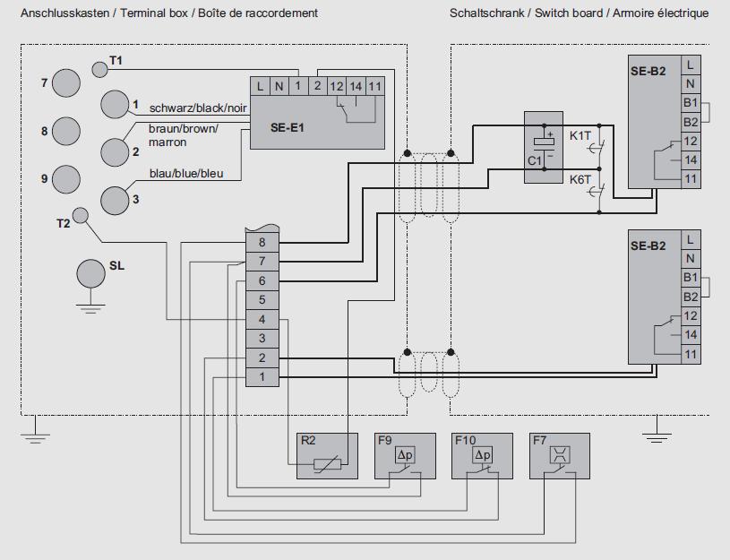
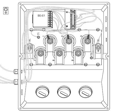
16 Section 6: Terminal Box Wiring Diagrams Example of terminal box wiring diagrams inside of the terminal boxes with ESC201 or SE-E1: HS53 Series with ESC201 HS53 Series with SE-E1 HS85 example of terminal box wiring diagram inside of the terminal box SE-E1 and SE-B Series: 15
17 16
18 Section 7: ESC200 Electronic Modules (HS53-64 and 74 Compressors) In depth information can be found in the respective manuals for each module. The following is a brief description and recommended action to perform for alarms. ESC200: This module was replaced by the updated ESC201 during Each ESC200 module must be powered by a 20 VAC center tap transformer. After any change or correction to the ESC200 configuration, the reset button must be depressed for the new configuration to take effect. ESC200 input voltage will read 5 VDC from any input terminal (A1 to A8) to terminal (B6) when the input device is open. ESC200 output voltage will read the voltage supplied at terminal (C8). Voltage can be read from the output terminal (D1-D8 and C4-C7) to L2 when the terminal is active. The following is a list of alarms with possible corrective solutions: 7.1 ESC200 will not power up: Check for 20 VAC control power to the ESC power plug. Check for proper electrical connections to the transformer and the ESC power plug. Check fuses F1 and F2 on the ESC. If blown, replace with 1 amp fuse. Verify to ensure total number of ESC controls have not exceeded the transformer rating. The minimum power requirement for (1) board is 500mA. 7.2 (C1) input signal is not present: Check for voltage and electrical connections between the compressor control switch, pressure controls, overload contacts and any other control devices to input (C1). 7.3 (C4) output point and (D1 thru D8): Check for proper input control voltage at alarm points. Terminals (C1) and (C8) do not respond with a voltage signal. Check ESC F3. If blown, replace with proper 3 amp fuse. 7.4 ESC200 operates intermittently: Make sure the ESC transformer has been properly grounded (center tap of secondary) by grounding the center tap of the ESC transformer and the B6 terminal point to a good ground. 7.5 F3 fuse blows when the ESC is energized: Check wiring of input and output points for a short. Disconnect (C1) control input and (C4) control output from the ESC and wire these points together isolating the ESC control. Activate the compressor control circuit. If the compressor contactor closes, de-activate the compressor control circuit and reconnect (C1 and C4) points on the ESC. Disconnect output points (C5), (C6) and (C7). Activate the compressor control circuit. If the compressor contactor closes, connect points (C6) and (C7) with the same procedure. If any of these checks produce a blown fuse, then check the corresponding circuit for the short. 17
19 7.6 Phase loss alarm turns on after a motor breaker closure while the control circuit is inactive: The phase voltage leads from the ESC are connected to the line side of the compressor contactor. Connect leads A, B, C to the load side of the contactor. The preferred location is the compressor terminals T1, T2, T Phase alarm (D6) turns on after the compressor has cycled off: The compressor contactor could possibly have a welded contact. Inspect all of the contacts in the contactor. Also check for ESC phase leads A, B, C are connected to the line side of the contactor. 7.8 ESC fails after an inverter fault: Compressor input signal (C1) remains active during inverter reset attempts. Check to ensure the inverter fault relay (IFR) is not defective. Check the control circuit wiring diagram to ensure the inverter isolation scheme included. 7.9 Phase rotation failure: Correct compressor rotation Rotation failure but compressor operates in the correct direction D7 alarm: The phase sequence of A, B, C on the ESC must be changed to match the proper electrical rotation sequence. Once the proper sequence has been determined and set, change any 2 leads of the phase leads on the ESC control to align the electricals. Check the wiring at terminals (A4) and (B6) Compressor will not activate for several minutes after control is energized: Check jumper "J2" to ensure it is in the "down" position for no time delay Open type compressors indicate motor overload failure: Check jumper "J1" for the "up" position which bypasses overload protection All compressors in the same suction group start at the same time: Check compressor start sequencing dip switches (SW 1.6 thru SW 1.8) for proper set-up Compressor fails on phase: Check to ensure the proper voltage exists at all terminals. Check to ensure compressor phasing is correct Discharge temperature failure D5 alarm: Check the discharge temperature to ensure it is not out of range. Check terminals (B2) and (B6). Check jumper "J3" for correct position (PTC sensor = jumper down or PT1000 sensor = jumper up). PTC100 will cut-out 4.5 K Ohms and cut-in 2.75 K Ohms. PT1000 will 1358 K Ohms and 1309 K Ohms Motor overload failure: Check the motor for out of range temperature conditions. Check terminal "B6" for proper ground. Check jumper "J1" for correct position. 18
20 7.17 Dirty oil filter failure alarm: If dirty filter alarms on initial starting, push the reset button to initialize the switch. Check for pressure drop across the filter and change the element if required. Alarm will occur if the differential is >10psi. Check "B6" terminal for proper ground connection. Check for proper wiring of the filter switch at A1 and B6. The switch must be wired N/C to operate properly. Element Condition Indicators: Visual 360o green/red auto reset Electrical/Visual 240VAC, 28VDC Electrical-Heavy Duty.25A(resistive) MAX 5 watts 12 to 28 VDC & 110 to 175 VAC Color code: White (common), Black (normally open), Blue (normally closed) 7.18 Oil flow failure D3 alarm: Check for possible low oil flows. Dirty oil filter, liquid refrigerant, pressure drops in the discharge piping, blocked or clogged oil supply, oil blank off plate at oil inlet was not removed can cause this alarm. Check "B6" terminal for proper ground connection. Check for proper wiring of oil flow switch. The flow switch connects to terminals (A2) and (B6). Check the dip switches for proper configuration. Automatic restart, switch 1.2 should be set to on. For Manual reset, switch 1.2 should be set to off. Check the oil solenoid valve and ensure it is connected to terminals (C7) and (L2) Oil level failure D4 alarm: The sensor is an electro-mechanical type which senses oil level and sends a signal through N/C contacts back to the ESC. If the oil falls below a safe level, the contacts will open causing the ESC to alarm. Check the oil level in the separator. Add if required. The level should always be visible in the sight glass while the compressor/s is/are in operation. Check the sensor for a 5 VDC signal to the sensor. Check "B6" for proper ground. Check for proper wiring to terminals (B7 Red) and (B6 Black). Note: the Red lead is connected to terminal (B&) on the Lead Compressor ESC200 only Resetting of the Control Functions: Automatic Reset: The ESC200 has several functions which are automatically reset when the appropriate dip switch is placed in the on or up position. Manual Reset: When any functions are set-up as manual reset, the function reset switch must be depressed to clear the fault. The reset button is located to the right of dip switch SW1. Each time a function is changed with the dip switch setting or jumper pin, the reset button must be depressed to initiate the change Switch 1 (SW1), Switch 2 (SW2) and Jumper 1 (J1): The dip switches and jumpers are set to specific compressor operation. SW1 are for the compressor settings are for discharge temperature, oil flow, phase monitor, motor overload, inverter and start delay. SW2 are for communication or network settings. J1 are for compressor functions: motor overload, short cycle delay, discharge thermistor and phase monitor. Refer to the operating manual for proper settings. 19
21 Section 8: ESC201 Electronic Modules (HS53-64 and 74 Compressors) In depth information can be found in the respective manuals for each module. The following is a brief description and recommended action to perform for alarms. ESC201: Each ESC201 module must be powered by a 24 volt non center tapped transformer. After any change or correction to the ESC201 configuration, the save button must be depressed for the new configuration to take effect. Line voltage inputs are terminals C-1, and 12. Line voltage outputs are terminals C-5, 7, 8, 9, 10 and 11. Digital input terminals are A1 thru A8. Analog input terminals are B1 thru B8. Input voltage will read 5VDC from the function terminals (A1-A6) to ground (A7) and from terminals (B1-B6) to ground (B7). Output terminals (C5-C11) are supplied voltage from terminal (C12). This voltage can be read from terminals (C5-C11) to L2 when the output function is closed. Terminals (C1-C4) are high voltage input terminals normally using control voltage as a source. Terminal (C10) is used for the alarm output. Digital display of compressor operation and alarm screen. The following is a list of symptoms with possible corrective solutions: For a complete description, refer to the operation manual ESC201MA ESC201 will not power up: Check for 24 VAC control power to terminals marked AC. Check for proper electrical connections to transformer or faulty transformer. Check "F2" fuse on the ESC board upper left corner. Check to ensure the total number of ESC201 controls has not exceeded the transformer in use. The minimum power requirement for (1) board is 760mA. The recommended transformer should have a rating of 900mA for a safety factor. Shielded cable should be used. 8.2 (C1) input is not present: Check for voltage and electrical connections between the compressor control switch, pressure controls, overload contacts and other control devices to input point "C1". 8.3 No output power at (C4-C11): Check for proper input voltage at terminals (C1-C11). 8.4 ESC operates intermittently: Make sure ground has a good non painted connection. The ESC201 has (3) separate ground connections. A shielded ground for the board and two separate grounds (A7 and B7) for the Digital and Analog inputs. Make sure all fuses are tight in each holder. 8.5 "F1" fuse blows when the ESC is energized: Turn off compressor breaker. Check wiring of input and output points for a short. 20
 points on the ESC. Disconnect output points (C7 to C11).")
22 Disconnect (C1) control input and (C5-C6) control output from the ESC and connect the wires together, isolating the ESC control. Activate the compressor control circuit. If the compressor contactor closes proceed as follows: De-activate the compressor control circuit and reconnect (C1, C5 and C6) points on the ESC. Disconnect output points (C7 to C11). Activate the compressor control circuit. If the compressor contactor closes, connect point (C7) and test this point. Test points (C8-C11) with the same procedure. If any of these tests produce a blown fuse, then check the circuit for the short. 8.6 Phase loss alarms after a motor breaker closure while the compressor control circuit is active: The phase voltage leads from the ESC201 are connected to the line side of the compressor contactor. Connect leads A, B, C to the load side of the compressor contactor. 8.7 ESC fails after an inverter fault: Compressor input signal (C1) remains active during inverter reset attempts. Check to ensure relay is not defective. Check control circuit wiring diagram to insure the inverter isolation scheme has been included. 8.8 All compressors in the same suction group start at the same time: Check the compressor start time delays to ensure they have been configured properly. 8.9 Wiring fault alarm: Check to ensure the three phase wires are connected to the load side of the compressor to the ESC201 connections. This fault will occur if the wires are connected to the line side Phase rotation failure: Correct compressor rotation Rotation failure but compressor operates in correct direction: Phase sequence A, B, C on the ESC201 must be changed to match the proper electrical rotation sequence. Once the proper sequence has been determined and set, change any two leads of the phase leads on the ESC201 control to match the system electrically. 21
23 8.12 Open type compressors indicate motor overload failure: The correct compressor type must be selected for the proper operation of the ESC201 and protection has been set-up for the compressor. Items that are automatically set-up by selecting the compressor type are motor protection, 7 minute time delay and analog oil flow requirements. The default compressor type is 74 semi. Access the main set-up screen and configure ESC201 in the set-up program for the motor overload as "disabled" after selecting either 53 open or 74 open Compressor fails on phase: Check voltage at all three phases to determine if voltage exists Discharge temperature failure: Check the discharge temperature for out of acceptable ranges. High suction superheat or insufficient oil cooling will cause this problem Critical discharge temperature alarm and compressor shuts down: If the discharge temperature exceeds 200 F, the loaders will be de-activated helping to lower the load on the compressor. If the discharge temperature falls below 194 F, the loaders will be activated. When the compressor remains in this critical discharge temperature range of 200 to 211 F for 20 minutes, the compressor will be shut down in the automatic restart mode. The compressor will restart and activate the loaders when the temperature falls below 194 F. The screen will display critical discharge temperature. When this alarm is displayed, all operational data is removed from the screen except for the discharge temperature. If the temperature continues to rise to the high limit of 212 F, the compressor will be shut down and high discharge temperature will be displayed. The compressor can be restarted when the temperature drops to 183 F, not the critical temperature of 194 F. Check oil cooling and other compressor cooling and superheat criteria Compressor shuts down on PTC sensor fault. The ESC201 can be selected to use two different temperature sensors. PT1000 or PTC100. Ensure the correct sensor has been selected in the programming section. To display the actual temperature on the screen while in operation, the PT1000 sensor must be used and selected. To operate Jet Kool oil cooling, Critical discharge temperature, High discharge temperature and low discharge temperature functions, the PT1000 must be used. Using the PTC100 temperature sensor will not display the actual temperature. Both sensors provide the temperature protection for the compressor with a shutdown temperature of 212 F. The standard delivery since 2009 has been the PTC100 sensor Motor overload failure: Check the motor temperature to determine if it is out of range. Read DC voltage between terminals (B1 & B7). The voltage should be stable between.3 and.6 VDC. The thermistor trip point is 2.3 VDC. Make sure all thermistor connections at the compressor are tight. Check the ESC201 set-up program for proper configurations Dirty oil filter failure: Each compressor is equipped with an oil filter. Located on the filter is a differential pressure switch which reads the pressure drop across each filter. If dirty filter alarms on initial starting, push the reset button to initialize the switch. Check for pressure drop across the filter and change the element if required. 22
 and (A7).")

24 The switch has two methods to indicate a dirty filter, a visual indicator located on top of the housing which will be green and turns red when dirty. There is also an electrical function which will close a set of contacts making a connection between terminals (A1) and (A7). When the ESC201 receives a signal, dirty oil filter will be displayed on the screen. Once a filter has been changed, the reset button must be depressed to clear the alarm. The dirty oil filter alarm is not a safety function for the compressor and does not shutdown the compressor. Alarm will occur if the differential is >25psi. Element Condition Indicators: Visual 360 green/red auto reset Electrical/Visual 240VAC, 28VDC Electrical-Heavy Duty.25A(resistive) MAX 5 watts 12 to 28 VDC & 110 to 175 VAC Color code: White (common), Black (normally open), Blue (normally closed) 8.19 Low oil level failure alarm: Sensor Specifications: Prism: Fused Glass Electrical: Voltage: 5VDC Current: 45mA Temperature Range: -40 F to 212 F O-Ring Size: #3-908 Housing Torque: 15 ft/lbs. Max. Color code: Black (ground), Red (5VDC), White (Signal) The oil level sensor is a two piece well with prism and the actual sending unit. The switch sends out a light beam that is refracted by the presence of oil. When oil level falls below a safe level, the light is no longer refracted opening the switch. In normal operation, a 5vdc signal is sent from the ESC201 to the switch and returned to the ESC201 indicating a proper oil level. When a low level situation occurs, all compressors affected will be shut down. When a compressor or ESC201 is configured as the master compressor, the compressor does not shutdown. This compressor remains in operation to perform the oil return function back to the oil separator. The oil safety for the master compressor is the oil flow switch. When oil level returns to a safe level, there is a 3 minute time delay before other compressors are allowed to be re-started. This prevents short cycling of a compressor due to possible rapid drop in the oil level. The oil level sensor is connected to the master ESC201 module. Check the oil level in the oil separator receiver for proper level. Check to see if the optical oil level sensor is receiving a 5 VDC signal. Check for loose wires from the sensor to the ESC201 which is (A2 and B8). 23

 and has a differential pressure rating of 45 psig. The HS64 and 74 series require a 10 liter (2.6 gpm) and have a differential pressure rating of 90 psig.")
25 8.20 Oil flow failure alarm: There have been 2 types of oil flow switches used. Analog oil flow switch was only used for a short period and have been obsoleted. The current oil flow switch is a Digital switch. The digital oil flow switch opens an electrical circuit which interrupts a signal back to the ESC201. The factory default on the ESC201 is the digital. The digital oil flow switch requires a differential pressure and a minimum oil flow to activate the switch. Two different oil switches are used depending on the size of the compressor. The HS53 series requires a 6 liter (1.6 gpm) and has a differential pressure rating of 45 psig. The HS64 and 74 series require a 10 liter (2.6 gpm) and have a differential pressure rating of 90 psig. If the contact is opened after the compressor reaches normal status, an alarm is shown low oil flow and the compressor is shutdown. Check for low oil flow conditions such as dirty oil filter, liquid refrigerant present in the system which will result in false oil flow signals, blocked or obstructed oil system. Check to ensure that the oil blank off plate has been removed from the inlet fitting to the compressor (new or replacement compressors). Check to ensure the oil flow switch has been properly wired to the ESC201 (A5 & A7). Check to ensure there is proper differential pressure between suction and discharge for proper oil flow which should be a minimum of 70 psi. This should be obtained a maximum of 20 seconds after compressor start. Current Obsolete 8.21 Compressor fails on runproof: Check to ensure runproofs are connected to the proper auxiliary contacts. Check "F1" fuse to make sure it is not blown. Make sure the runproof signal on direct on line starting is connected to (C4) with VAC. Make sure the direct on line and the inverter runproof are being energized together. Refer to the wiring diagrams shown in the manual for your particular set-up Low ECO temp and Low Discharge temp: Low Economizer Temp: If the compressor discharge temperature is determined to be less than or equal to 35 F above the condensing temperature for 30 minutes, the ESC201 will alarm low discharge temperature. The economizer output terminal (C11) will shut down the economizer solenoid for 5 minutes. At the end of 5 minutes, the discharge temperature will be checked to determine if it has risen to at least 45 F above the condensing temp. If not, the ESC201 will shut down the economizer requiring a manual reset and the alarm Low Eco Temp will be displayed. The actual discharge temperature remains below the condensing temperature by at least 50 F; the chance exists for condensing the refrigerant prior to exiting the compressor discharge. Low temperature can be attributed in many cases to low superheat at the economizer inlet. This can cause premature bearing wear resulting in compressor damage. When the Low Discharge Temperature alarm appears, the cause can be attributed to low superheat or liquid refrigerant entering the compressor suction. 24
Copeland Screw TM Compressors
 Copeland Screw TM Compressors Mechanical Guidelines for SHL & SHM Models using ESC-201 Control System Contents: Start-Up Procedure Operating Specifications Maintenance Trouble Shooting Guidelines Start-up
Copeland Screw Compressors Semi-Hermetic Compact Operating Instructions
 Copeland Screw Compressors Semi-Hermetic Compact Operating Instructions SCH2 & SCA2 High Temperature Compressors 35-240 Horsepower 1. Introduction This series of semi-hermetic compact screw compressors
Application Engineering
 Application Engineering February, 2009 Copeland Digital Compressor Controller Introduction The Digital Compressor Controller is the electronics interface between the Copeland Scroll Digital Compressor
BRIVIS DUCTED INVERTER SERVICE MANUAL DRCi
 BRIVIS DUCTED INVERTER SERVICE MANUAL DRCi 1 TABLE OF CONTENTS TABLE OF CONTENTS... 2 IMPORTANT NOTE... 3 FAULT FINDING AND DIAGNOSTICS... 3 ABBREVIATIONS... 3 PCB S... 4 OUTDOOR MAIN PCB... 4 INDOOR PCB...
Application Engineering
 Application Engineering March 2011 Copeland Digital Compressor Controller Introduction The Digital Compressor Controller is the electronics interface between the Copeland Scroll Digital compressor or the
Application Engineering Europe
 Date of last update: Feb-12 Ref: D7.8.4/0112-0212/E Application Engineering Europe CORESENSE DIAGNOSTICS FOR STREAM REFRIGERATION COMPRESSORS 1/17 1 Introduction CoreSense is an ingredient brand name for
Wiring diagrams on page 29 are for reference only. For detailed vehicle wiring refer to Navistar documents.
 1 10/2014 REV 7 !!Attention!! Before performing diagnostics: Wiring diagrams on page 29 are for reference only. For detailed vehicle wiring refer to Navistar documents. Check for Fault Codes using the
Replacing the Internal Oil Filter Elements for HS85 and OS 85 Screw Compressors
 Maintenance Bulletin (MB-0038) Version 1, Sept 2015 Replacing the Internal Oil Filter Elements for HS85 and OS 85 Screw Compressors The internal oil filter elements are recommended to be changed on new
CORESENSE DIAGNOSTICS FOR STREAM REFRIGERATION COMPRESSORS
 Date of last update: Apr-15 Ref: D7.8.4/0112-0415/E Application Engineering Europe CORESENSE DIAGNOSTICS FOR STREAM REFRIGERATION COMPRESSORS CoreSense Diagnostics for Stream Refrigeration Compressors...
348002K/348012K Manifold Block Style Service Manual 12/2000
 348002K/348012K Manifold Block Style Service Manual 12/2000 Service Manual 348002K/348012K Manifold Block Style Recovery/Recycling/Recharging Unit For R-12 or R-134a Only TABLE OF CONTENTS: Theory of Operation
Bitzer CSH Series To Fusheng
 Bitzer CSH Series To Fusheng Competitive Replacement Guideline M-BSR-EC3-201604 FUSHENG Screw Compressor BSR Series The intention of this document is to serve as general guidelines. The information contained
SECOND GENERATION Use this guide with unit serial number prefix beginning with BWF using Terra Power separator.
 Technical Information and Diagnostic Guide for SECOND GENERATION Use this guide with unit serial number prefix beginning with BWF using Terra Power separator. This guide will assist you in becoming more
Trouble Shooting. Symptom Possible Cause Solution Power switch ON but switch Light is Off. Main power to unit Off. Switch light defective.
 Trouble Shooting TE: Should the OAM Purger shut down on a FAULT condition, DO T POWER OFF THE PURGER until you have first removed the electrical panel cover and recorded the status of the indicator LED
HP21 SERVICE SUPPLEMENT UNIT INFORMATION. TSC6 Two-Speed Control
 SERVICE UNIT INFORMATION SUPPLEMENT HP21 Corp. 9426 L10 Litho U.S.A. All HP21-4 and -5 units (single and three phase) are equipped with a TSC6 two-speed control. The TSC6 (A14) two-speed control contains
OIL PRESSURE SAFETY CONTROLS
 8-1095 Application Engineering Bulletin AE-1095-R9 Revised September 1, 1981 OIL PRESSURE SAFETY CONTROLS A major percentage of all compressor failures are caused by lack of proper lubrication. Improper
XCITE Owner s Manual. Reso-not TM Damping System XCITE 1502C HYDRAULIC POWER SUPPLY
 Reso-not TM Damping System XCITE Owner s Manual 1502C HYDRAULIC POWER SUPPLY Xcite Systems Corporation 675 Cincinnati RDS Batavia - 1 Pike Cincinnati, Ohio 45245 Tel: (239) 980-9093 Fax: (239) 985-0074
Modulating Furnace Information. Warning on Meter Setting - Read First!
 Modulating Furnace Information Pressure Transducer Pressure DC Volts 0.00" 0.25 0.20" 0.63 0.25" 0.72 0.30" 0.82 0.35" 0.91 0.40" 1.00 0.45" 1.09 0.50" 1.19 0.55" 1.28 0.60" 1.38 0.65" 1.47 0.70" 1.56
BITZER Liquid Injection Guidelines for CSH Compressors
 BITZER Liquid Injection Guidelines for CSH Compressors Liquid Injection Additional cooling may be required during reduced capacity operation, high condensing and / or low evaporating temperatures. Direct
BLOWER VACUUM SWITCH FAILED OPEN
 F1 F1 AC BLOWER VACUUM SWITCH FAILED CLOSED AC BLOWER VACUUM SWITCH FAILED CLOSED UHS If the blower vacuum switch is closed before blower start-up, the control module will not start the blower. Pre-check
6 Litre Oil-Less Air Compressor
 Operator s Manual 6 Litre Oil-Less Air Compressor WARNING! Before using this appliance, read the Operator s manual and follow all its safety rules and instructions. SPECIFICATION HWKAC1 1.1 kw / 1.5 HP
Subject Underhood G System Error Codes and Symptoms System or Parts affected
 System or Parts affected Index Underhood70G (V90Gxxx) System or Parts affected... 1 Overview... 1 Identifying your System... 1 Retrieving Logged Error Messages... 1 Error Messages... 3 Error Message Table...
MODEL 422 Submersible Pump Controller
 MODEL 422 Submersible Pump Controller Monitors True Motor Power (volts x current x power factor) Detects Motor Overload or Underload Operates on 120 or 240VAC, Single-phase or 3-phase Built-in Trip and
DUST COLLECTOR (BOTTOM REMOVAL BAG & CAGE) INSTALLATION AND OPERATING INSTRUCTIONS
 INSTALLATION AND OPERATING INSTRUCTIONS") 4080 SE International Way. Suite B110, Milwaukie, OR 97222 (503) 654-0867 Fax: (503) 654-4671 email: ftech@filtertechnologyltd.com www.filtertechnologyltd.com DUST COLLECTOR (BOTTOM REMOVAL BAG & CAGE)
4080 SE International Way. Suite B110, Milwaukie, OR 97222 (503) 654-0867 Fax: (503) 654-4671 email: ftech@filtertechnologyltd.com www.filtertechnologyltd.com DUST COLLECTOR (BOTTOM REMOVAL BAG & CAGE)
Troubleshooting the Transmission Hydraulic System
 Testing and Adjusting IT28F INTEGRATED TOOLCARRIER POWER TRAIN Testing And Adjusting Introduction Reference: For Specifications with illustrations, refer to SENR5974, IT28F Integrated Toolcarrier Power
ACSI MODEL 1406BB-04-AO POWER SUPPLY INSTALLATION INSTRUCTIONS
 II 1400-10 ACSI MODEL 1406BB-04-AO POWER SUPPLY INSTALLATION INSTRUCTIONS Features: Up to 1.95 Amps Load Capacity Class 2 Rated Outputs Overload, Over Voltage, and Short Circuit Protection Standby Battery
ACCESSORY KIT INSTALLATION INSTRUCTIONS
 ACCESSORY KIT INSTALLATION INSTRUCTIONS Low Ambient Accessory For Air Cooled Split-System Air Conditioners YD360/480/600, YJ-30/-40/-50 and J30/40/50 YD Models 642546-UAI-A-080 GENERAL Standard operation
Third Generation NITE Phoenix
 Technical Information and Diagnostic Guide for Third Generation NITE Phoenix Use this guide with unit serial number prefix beginning with BYC, CAI built after 2-10-2012 and CCA, CDJ, CIA units after 6/25/2012
ICM 326HN/327HN Line Voltage Head Pressure Control Installation, Operation & Application Guide
 ICM 326HN/327HN Line Voltage Head Pressure Control With built-in transformer Optional heat pump override ICM326HN ICM327HN Installation, Operation & Application Guide For more information on our complete
ZIP Economizer Fault Detection and Diagnostics (FDD) Table
 Table") Fault Detection and Diagnostics (FDD) Table Fault Detection Problem Diagnostic ction (in addition to alarm stored / transmitted) Potential Cause C Fault Code OT sensor predetermined range O damper returns
Fault Detection and Diagnostics (FDD) Table Fault Detection Problem Diagnostic ction (in addition to alarm stored / transmitted) Potential Cause C Fault Code OT sensor predetermined range O damper returns
Operation & Service Manual
 Operation & Service Manual Model: 5010 Hydraulic Power Unit 05/2004 - Rev. 01 Includes Illustrated Parts Lists 1740 Eber Rd Tronair, Inc. Phone: (419) 866-6301 Holland, OH 43528-9794 www.tronair.com 800-426-6301
A/C-HEATER SYSTEM - AUTOMATIC
 A/C-HEATER SYSTEM - AUTOMATIC 1988 Toyota Celica 1988 Automatic A/C-Heater Systems Celica * PLEASE READ THIS FIRST * CAUTION: When discharging air conditioning system, use only approved refrigerant recovery/recycling
Technical Information and Diagnostic Guide
 Technical Information and Diagnostic Guide This guide will assist you in becoming more familiar with the working components of the NITE System and the proper steps and procedures to completely diagnose
A/C SYSTEM GENERAL DIAGNOSTIC PROCEDURES
 Article Text ARTICLE BEGINNING 1993 AIR CONDITIONING & HEAT A/C General Diagnostic Procedures Diagnosis is an important first step in A/C system servicing. To save time and effort, systems should be carefully
LG Air conditioning CAC and Multi Split unit Fault code sheet Universal and Multi Split Units
 Universal and Multi Split Units If there is fault on any LG universal or multi unit a two digit number will appear on the remote controllers led display. If the unit does not have a remote controller the
1333 (SERIES B & C) TROUBLESHOOTING GUIDE
 TROUBLESHOOTING GUIDE") 1333 (SERIES B & C) TROUBLESHOOTING GUIDE Preventive Maintenance: Problems with Your Drive? Bulletin 1333 is convection or fan cooled by air flowing through the heat sink slots. The slots must never be
1333 (SERIES B & C) TROUBLESHOOTING GUIDE Preventive Maintenance: Problems with Your Drive? Bulletin 1333 is convection or fan cooled by air flowing through the heat sink slots. The slots must never be
Hayward error codes and troubleshooting
 http://waterheatertimer.org/intermatic-trippers-and-parts.html#pool 50 Hayward error codes and troubleshooting Section V. TROUBLESHOOTING http://www.hayward-pool.com/prd/in-ground-pool-manuals_10201_10551_14502_-1
PT, PTS & PTP Series Pump/Reservoirs
 PT, PTS & PTP Series Pump/Reservoirs Installation, Operation and Maintenance Manual Table of Contents FOREWORD... 1 INSTALLATION... 1 RECEIVING INSPECTION... 1 RIGGING, HANDLING, AND LOCATING EQUIPMENT...
General safety references:
 www.bitzerus.com 1 The intention of this document is to serve as general guidelines. The information contained is not intended to replace specific equipment and/or system manufacturer's information or
 Page 1 of 29 Section 04-05: Suspension, Computer Controlled 1997 Town Car Workshop Manual DIAGNOSIS AND TESTING Procedure revision date: 05/16/2000 Suspension, Computer Controlled Inspection and Verification
Power Distribution System User s Manual. Model: PDS-100
 Power Distribution System User s Manual Model: PDS-0 Section Page Product Overview... 1 I) General Information... 2 II) Important Safety Information... 2 III) Installation... 3 A) Materials Provided...
ARM V FDBK ENSURE MOTOR IS NOT ROTATING DURING POWER UP STILL FAULTS? YES ENSURE ARMATURE WIRING IS ISOLATED FROM ANY OTHER POWER LEADS STILL FAULTS?
 ARM V FDBK ENSURE MOTOR IS T ROTATING DURING POWER UP This fault can only happen in the first 3 seconds after power up. The processor looks at the armature voltage. The voltage needs to be near 0. Possible
LG Air Conditioning Universal & Multi Split Fault Codes Sheet. Universal and Multi Split Units
 Universal and Multi Split Units If there is a fault on any LG Universal or Multi unit, a two digit number will appear on the remote controllers led display. If the unit does not have a remote controller
Series 20 Installation Instructions
 Series 20 Installation Instructions Installation Instructions and field service checklist Read these instructions carefully. Failure to follow them could result in a fire or explosion causing property
ADVANCED PID TROUBLESHOOTING
 ADVANCED PID TROUBLESHOOTING August 29, 2016 A KEY POINT If the drive is telling you something via a Fault, then the problem is probably not the drive. The drive is recognizing a fault and telling you
SPLIT-SYSTEM AIR-COOLED CONDENSING UNITS DESCRIPTION FEATURES H2CA300, 360, 480 & THRU 50 NOMINAL TONS
 550.13-TG1Y(98) SPLIT-SYSTEM AIR-COOLED CONDENSING UNITS HCA300, 360, 80 & 600 5 THRU 50 NOMINAL TONS HCA80 DESCRIPTION These units are completely assembled, piped and wired at the factory to provide one-piece
ICM325HN. Head Pressure Control with Optional Heat Pump Override. Installation, Operation & Application Guide
 ICM325HN Head Pressure Control with Optional Heat Pump Override Temperature sensitive control regulates head pressure Installation, Operation & Application Guide For more information on our complete range
P445 Series Electronic Lube Oil Control
 FANs 125, 121 s Section P Product/Technical Bulletin P445 Issue Date 0100 P445 Series Electronic Lube Oil The P445 Series Electronic Lube Oil is designed for use on refrigeration compressors equipped with
HALLMARK INDUSTRIES INC
 Performance Part No. HP. CONVERTIBLE JET PUMP USER S MANUAL GPH of Water @ Total Discharge Pressure of 40 psi Max. Pressure Max suction (shallow well) Max Suction (deep well) Max GPM (@0 head) Max Discharge
CHILLER START UP PROCEDURE FORM DOC. N (DOC.N BELOW TO BE RETURN TO AERMEC)
") CHILLER START UP PROCEDURE FORM DOC. N 061103 (DOC.N 071103 BELOW TO BE RETURN TO AERMEC) 1. Preliminary Operation WARNING: The following operation must be done without the power supply (unit with the
CHILLER START UP PROCEDURE FORM DOC. N 061103 (DOC.N 071103 BELOW TO BE RETURN TO AERMEC) 1. Preliminary Operation WARNING: The following operation must be done without the power supply (unit with the
Electronic Products ELECTRONIC MAINTENANCE
 SubDrive2W, 75, 100, 150, 300, MonoDrive, and MonoDrive XT Should an application or system problem occur, built-in diagnostics will protect the system. The FAULT light or digital display on the front of
SECTION 3.00 WARNING WARNING ENGINE STARTUP AND SHUTDOWN PRESTART INSPECTION
 SECTION 3.00 ENGINE STARTUP AND SHUTDOWN PRESTART INSPECTION Be sure that the clutch, circuit breaker, or other main power transmission device is disconnected. Generators develop voltage as soon as the
Purging Air From Divider Block Lubrication Systems
 FROST ENGINEERING SERVICE Purging Air From Lubrication Systems A D I V I S I O N O F G E C S E Y S A L E S & S E R V I C E DESCRIPTION Divider block lubrication systems operate correctly only when all
WARNING. Murphy W-Series Engine Panels General Installation Instructions. Installation Accessories
 Murphy W-Series Engine Panels General Installation Instructions WS-93002N Revised 04-06 Section 30 (00-02-0191) Read the following information before installing. These installation instructions are typical
Section 10 Chapter 7
 Section 10 Chapter 7 24 Valve, 8.3 Liter Engine Troubleshooting Symptoms Identification Note: All coding used in the 8.3 Liter and 9 Liter engine manuals are Cummins engine codes. These engine codes have
WARNING. Murphy W-Series Engine Panels General Installation Instructions. Installation Accessories
 Murphy W-Series Engine Panels General Installation Instructions WS-93002N Revised 08-02 Section 30 (00-02-0191) Read the following information before installing. These installation instructions are typical
Service and Parts Manual. NO LONGER IN PRODUCTION Some service parts may not be available for this product. Otolaryngology Chair.
 thru 391-001 -002 Otolaryngology Chair Serial Number Prefixes: EN, PD & V Service and Parts Manual NO LONGER IN PRODUCTION Some service parts may not be available for this product. 391-001 thru -002 NOTE:
COOKSON OWNER'S MANUAL
 COOKSON OWNER'S MANUAL FDO-A10 INDUSTRIAL DUTY FIRE DOOR OPERATOR R L I S T E D 3040233 US CONTROL PANEL SERIAL# OPERATOR SERIAL# 9001.DWG ECN 0959 REV 4 SPECIFICATIONS MOTOR TYPE:...INTERMITTENT HORSEPOWER:...1/8
SOLAR LIGHTING CONTROLLER SUNLIGHT MODELS INCLUDED IN THIS MANUAL SL-10 SL-10-24V SL-20 SL-20-24V
 SOLAR LIGHTING CONTROLLER OPERATOR S MANUAL SUNLIGHT MODELS INCLUDED IN THIS MANUAL SL-10 SL-10-24V SL-20 SL-20-24V 10A / 12V 10A / 24V 20A / 12V 20A / 24V 1098 Washington Crossing Road Washington Crossing,
Valcom Failsafe Unit. 1620ESv2 SERIES. Operation and Maintenance Manual
 Valcom Failsafe Unit 1620ESv2 SERIES Operation and Maintenance Manual Table of Contents Section Title Page 1. - Introduction.. 2. - Unpacking the Failsafe unit. 3. - Installation 3.1 - Auto / Timed UPS
32XR. 3 Phase Duplex Pump Control Panel (Level Transmitter Based) Quick Start Guide
 Quick Start Guide") 32XR 3 Phase Duplex Pump Control Panel (Level Transmitter Based) Quick Start Guide RED ALARM LIGHT LEVEL CONTROLLER H-O-A SWITCHES HORN SILENCE INNER DOOR MOTOR STARTERS WITH INTERCHANGEABLE OVERLOAD MODULES
32XR 3 Phase Duplex Pump Control Panel (Level Transmitter Based) Quick Start Guide RED ALARM LIGHT LEVEL CONTROLLER H-O-A SWITCHES HORN SILENCE INNER DOOR MOTOR STARTERS WITH INTERCHANGEABLE OVERLOAD MODULES
CIRCLE SEAL CONTROLS
 CIRCLE SEAL CONTROLS ATKOMATIC SOLENOID VALVES INSTALLATION, MAINTENANCE, AND OPERATION INSTRUCTIONS 13000 SERIES Stainless, Normally Closed, Direct Lift, 3-Way Valve Installation Instructions WARNING:
Engine Performance Troubleshooting Tree - Signature and ISX CM870
 File: 70-t02-1001 Page 1 of 64 Engine Performance Troubleshooting Tree - Signature and ISX CM870 This troubleshooting procedure should be followed for the following symptoms: Engine Acceleration or Response
LEAD FREE * LFF113RFP Flood Protection Shut Down Valve
 Technical Bulletin TB-ACV-LFF11RFP LEAD FREE * LFF11RFP Flood Protection Shut Down Valve Installed upstream of Reduced Zone Backflow Preventer. Normally Open Valve - Closes when continuous discharge from
PROBLEM SOLVING GUIDE ELMECO SLUSH MACHINE MODEL FCM
 A01 INSTRUCTIONS ON HOW TO READ REFERENCES...2 A10 FEATURES AND TECHNICAL SPECIFICATIONS...3 A15 RECOMMENDED PREVENTIVE MAINTENANCE SPARE PARTS KIT...3 A20 IMPORTANT INFORMATION ON FUNCTIONALITY OF THE
User Manual. T6 Tachometer. Online: Telephone: P.O. Box St. Petersburg, Florida 33736
 User Manual T6 Tachometer Online: www.phareselectronics.com Telephone: 727-623-0894 P.O. Box 67251 St. Petersburg, Florida 33736 Table of Contents Overview... 1 Description... 1 Wiring... 1 T6 Tachometer
INSTALLATION INSTRUCTIONS
 INSTALLATION INSTRUCTIONS Universal Air Series!! NOTE!! Covers the following model: 6000 Series 85-0100B-AZ Rev 0 5/07 To ensure that the system is installed properly, provide your electrician with these
Operation & Service Manual
 Operation & Service Manual Model: 5B20 Hydraulic Power Unit 07/2011 - Rev. 06 Includes Illustrated Parts Lists 1740 Eber Rd Tronair, Inc. Phone: (419) 866-6301 Holland, OH 43528-9794 www.tronair.com 800-426-6301
INSTALLATION/OPERATION/MAINTENANCE INSTRUCTIONS FOR ARCHON MODELS WD2010L, WD2010, WD2010H WASHDOWN STATIONS. ARCHON Industries, Inc.
 ARCHON Industries, Inc. Washdown Stations Models WD2010L, WD2010, WD2010H Installation / Operation / Maintenance Instructions 1 This manual has been prepared as an aid and guide for personnel involved
Art. No. EC-315. Art. No. EC-330. Art. No. EC-340 SWITCH-MODE BATTTERY CHARGER CONTENTS IMPORTANT SAFETY PRECAUTIONS... 2
 SWITCH-MODE BATTTERY CHARGER CONTENTS IMPORTANT SAFETY PRECAUTIONS... 2 DESCRIPTION AND FEATURES... 3 CHARGING STAGES... 4 Art. No. EC-315 Art. No. EC-330 Art. No. EC-340 PROTECTIONS... 5 INSTALLATION...
331-SV. User Manual THREE PHASE DUPLEX LIFT STATION CONTROL PANEL WITH STATIONVIEW CONTROLLER. Ashland, OH
 331-SV User Manual THREE PHASE DUPLEX LIFT STATION CONTROL PANEL WITH STATIONVIEW CONTROLLER Ashland, OH 800-363-5842 WWW.PRIMEXCONTROLS.COM Warranty void if panel is modified. Call factory with servicing
2015 EDITION SUBMERSIBLE MOTORS AIM MANUAL. APPLICATION INSTALLATION MAINTENANCE 60 Hz, Single-Phase and Three-Phase Motors. franklinwater.
 0 EDITION AIM MANUAL SUBMERSIBLE MORS APPLICATION INSTALLATION 60 Hz, Single-Phase and Three-Phase Motors franklinwater.com All Motors System Troubleshooting Motor Does Not Start A. No power or incorrect
6L Oil-less Air Compressor 53103
 6L Oil-less Air Compressor 53103 Operating Instructions Please read and save these instructions before attempting to assemble, install, operate or maintain the product. Protect yourself and others by observing
Advantage-D. Operating Instructions and Maintenance Manual. Central Vacuum Systems (Expandable/Modular Models) (Ver.
 (Ver.") Advantage-D Series 3 Central Vacuum Systems (Expandable/Modular Models) (Ver. 8/05) Operating Instructions and Maintenance Manual DESCRIPTION The Becker Advantage-D and Advantage-L central vacuum systems
Advantage-D Series 3 Central Vacuum Systems (Expandable/Modular Models) (Ver. 8/05) Operating Instructions and Maintenance Manual DESCRIPTION The Becker Advantage-D and Advantage-L central vacuum systems
SERVICE MANUAL (DOMESTIC & INTERNATIONAL)
") SERVICE MANUAL (DOMESTIC & INTERNATIONAL) DUAL TECHNOLOGY FINISHER MODEL 1960 & 1980 SERIES Lincoln Foodservice Products, LLC 1111 North Hadley Road Fort Wayne, Indiana 46804 United States of America Telephone:
SERVICE MANUAL (DOMESTIC & INTERNATIONAL) DUAL TECHNOLOGY FINISHER MODEL 1960 & 1980 SERIES Lincoln Foodservice Products, LLC 1111 North Hadley Road Fort Wayne, Indiana 46804 United States of America Telephone:
R & D SPECIALTIES ROTROL I USER'S MANUAL
 R & D SPECIALTIES ROTROL I USER'S MANUAL TABLE OF CONTENTS INTRODUCTION...2 SPECIFICATIONS...2 CONTROLS AND INDICATORS...3 TIME DELAYS...4 INSTALLATION...5 SYSTEM OPERATION...9 TROUBLESHOOTING...13 OPTIONAL
Routine Compressor Maintenance
 Establishing a regular, well-organized maintenance program and strictly following it is critical to maintaining the performance of a compressed air system. One person should be given the responsibility
CENTRIFUGAL CHILLER. Lubrication System Pull oil sample for spectroscopic analysis.
 CENTRIFUGAL CHILLER Annual Inspection Refrigerant Circuit Check and record refrigerant level Inspect for leak results Calculate refrigerant lass and report to the customer. Repair minor leaks as required
Secondary Coolant 301
 Secondary Coolant 301 Instructor Rusty Walker Hill PHOENIX Learning Center Secondary Coolant 301 Start-Up Procedures Secondary Coolant 301 Objectives Describe the initial startup procedures for a medium
Reproduction or other use of this Manual, without the express written consent of Vulcan, is prohibited.
 SERVICE MANUAL ELECTRIC BRAISING PANS (30 & 40 GALLON) VE30 VE40 ML-126849 ML-126850 VE40 SHOWN - NOTICE - This Manual is prepared for the use of trained Vulcan Service Technicians and should not be used
Advanced EasyStart Troubleshooting
 Advanced EasyStart Troubleshooting EasyStart is designed for excellent reliability and durability. Every EasyStart is tested on a compressor before it leaves Micro-Air to ensure it will work when delivered.
6. Document tasks performed during visit and report any observations to the appropriate
 Chiller Annual Maintenance RFP Attachment B Services Required Tasking: Vibration Analysis 1. All work shall be performed in accordance with safety policies 2. Check with appropriate customer representative
Technical Information and Diagnostic Guide RestStar Use this guide with 5700XE RestStar Unit. Western Star 5700XE.
 Western Star 5700XE RestStar 4 10-2017 1 Technical Information and Diagnostic Guide RestStar Use this guide with 5700XE RestStar Unit 2390 Blackhawk Road P.O. Box 6007 Rockford, IL 61125 nitesystem.com
Rack Oil regulation and System Oil Failures
 Rack Oil regulation and System Oil Failures Bryan Lord 2009 Oil failure alarms are usually more than just a compressor safety control failure or low oil pressure event. Unfortunately OFC alarms are just
ECU-02 Ver2.1 Automatic Engine Control Unit Operators Manual
 ECU-02 Ver2.1 Automatic Engine Control Unit Operators Manual Headquarters : No.3, Lane 201, Chien Fu St., Chyan Jenn Dist., Kaohsiung, TAIWAN Tel : + 886-7-8121771 Fax : + 886-7-8121775 URL : http://www.kutai.com.tw
Irrigation Components International, Inc.
 1500 Irrigation Components International, Inc. P.O. Box 945 Daphne, AL 36526 USA Tel: 251.626.5470 Fax: 251.447.0190 Email: icii@irricomp.com Visit us on the web: www.irricomp.com 1500 TABLE OF CONTENTS
Fault Codes. J control
 J control Timer Temp Fault Codes 12 11 10 9 8 7 6 5 4 3 2 1 30 29 28 27 26 25 24 23 22 21 20 Enter unit inspection mode by pushing the UP and DOWN buttons simultaneously for two seconds. Ensure that the
KE2 FanControl Installation Instructions
 Installation N.2.1 November 2011 Installation Instructions KE2 Therm Solutions Providing Advanced Energy Saving Technology for Commercial Refrigeration and AC Systems Page 2 For condensed installation
Crispin Valves Operating Guide. Crispin
 Crispin Valves Operating Guide Crispin Since 1905 Crispin Multiplex Manufacturing Co. 600 Fowler Avenue Berwick, PA 18603 1-800-AIR-VALV T: (570) 752-4524 F: (570) 752-4962 www.crispinvalve.com sales@crispinvalve.com
NSGV PT-1000 PORTABLE WELDING STATION I, O & M MANUAL
 APPLICATION OF DUST CONTROL EQUIPMENT: CAUTION - Warning Improper operation of dust control system may contribute to conditions in the work area or facility that could result in severe personal injury
9/28/2018. Refrigeration compressor operation, maintenance and safety
 Refrigeration compressor operation, maintenance and safety Presented By: Dhananjay S. Deshpande Company name: Technex HVAC&R Engg. Works 304, Shivshakti CHS, Sector 09, Plot no 15, Khanda colony, New Panvel
MODEL 520 REMOTE START ENGINE MANAGEMENT SYSTEM
 MODEL 520 REMOTE START ENGINE MANAGEMENT SYSTEM DSE 520 ISSUE 4 4/4/02 MR 1 TABLE OF CONTENTS Section Page INTRODUCTION... 4 CLARIFICATION OF NOTATION USED WITHIN THIS PUBLICATION.... 4 1. OPERATION...
HVF110, 210, 310, 410HD
 342 N. Co. Rd. 400 East Valparaiso, IN 46383 219-464-8818 Fax 219-462-7985 www.heatwagon.com Installation and Maintenance Manual Please retain this manual for future reference. HVF110, 210, 310, 410HD
J1 Plug Pin Identification
 D D8 D D D D ART_8 J 8 D D0 R R R R TB 80 D D D D D D J Plug Pin Identification PIN # WIRE # SIGNAL FUNCTION 0 INPUT Drive Reverse INPUT Drive Forward OUTPUT Brake, Decel Valve signal 8 INPUT Steer Left
A/C PRESSURE MONITOR INSTALLATION INSTRUCTIONS SYSTEM OPERATION GREEN INDICATOR LIGHT
 A/C PRESSURE MONITOR INSTALLATION INSTRUCTIONS Do not attempt to clean or inspect anything while the engine is running. Cleaning and inspection must be done by a certified mechanic. All A/C service must
Pure Sine Wave Inverter GP-HS1500. Owner s Manual
 Pure Sine Wave Inverter GP-HS1500 Owner s Manual 2 Table of Contents Introduction 3 Specifications 4 Name and Main Function 5 Installation 7 Operation 9 Operating Limits 13 Troubleshooting 13 Maintenance
Farval. Dualine Installation System Start-Up. Bulletin DL300 BIJUR DELIMON INTERNATIONAL
 Farval Dualine Installation System Start-Up Bulletin DL300 BIJUR DELIMON INTERNATIONAL 2685 Airport Road Kinston, NC 28504 Tel. 800-227-1063 Fax: 252-527-9232 website: www.bijurdelimon.com DC1-1 SECTION
TECHNICAL SERVICE DEPARTMENT Technical Service Bulletin LowNOx Commercial Gas Electronic Spark Ignition Sequence
 The Universal TM gas LowNOx series water heaters contain an electronic spark ignition system. The heater is connected to a 120VAC power source required by the transformer. The transformer steps down the
Safe & Secure Series Electric Actuator with Internal Battery Back-up Installation, Operation & Maintenance Manual
 Safe & Secure Series Electric Actuator with Internal Battery Back-up Installation, Operation & Maintenance Manual For Use with: SNS4, SNS6, SNS10 & SNS15 Models Additional supplements may be needed for
Pump Installation and Service Manual HRS Hydromatic Retractable System
 Pump Installation and Service Manual HRS Hydromatic Retractable System NOTE! To the installer: Please make sure you provide this manual to the owner of the pumping equipment or to the responsible party