2014 Hydraulic Power Packs AC & DC Compact
|
|
|
- Willa McKenzie
- 6 years ago
- Views:
Transcription


1 14 Hydraulic ower acks C & DC Compact


2 Why choose Hydronit? ± Complete focus on hydraulic components & modular power packs design, continuous research, development and innovation ± Expertise on hydraulic applications; design and development of customised solutions, including special manifolds, ex-proof units, proportional systems,... ± Organization fully based on processes and otal Quality Management principles, certified ISO 91:8 and ISO 51:11 ± Lean and energy efficient product design and manufacturing ± Mass production and cost optimization: hundreds of thousands of Hydronit modular power packs are now reliably running worldwide ± Flexible marketing policy: supply of loose hydraulic components and power packs either in kit or fully assembled and tested in accordance with Machine Directive 6/4/CE ± Distributors, associate companies and partners in over 5 countries worldwide


3 Hydronit - he sustainable factory ± roduction is carried out in a building of 3 13 m requiring almost no use of fossil fuels to operate ± he hyper insulation of the structure through the use of materials, mainly natural, such as wood and cork, ensures 3 a consumption of only 7,4 kwh/m /year for winter heating and for summer cooling 3 only 3, kwh/m /year ± heat pump provides high efficiency thermal regulation ± system of 6 solar panels on the roof of the offices provides 13,8 kw of electrical power that contributes about 6% of the electricity consumed by the plant for its own operation ± Solar thermal panels provide hot water ± he automatic wharehouses and the line of semi-automatic assembly increase efficiency, reduce process paperwork and human errors, thus ensuring compliance with stringent quality standards and repeatable test results


4 Continuous innovation Hydronit Srl, in the pursuit of excellence, have dedicated a large part of their profits to research and continuous development of the product, in order to increase the performance, efficiency, durability and reliability over time, and for the continuous improvement of the organization, constantly monitoring parameters over thirty indicators of the efficiency and effectiveness of the organization as a whole. Nanotechnology surface treatment Hydronit Srl, in partnership with research institutions and external bodies, co-financed by the Lombardy Region, has initiated some years ago a project for the development of advanced applications of plasma surface treatment of metallic materials. In short it is the application of nanotechnology to hydraulic equipment to improve the performance of our units. We have obtained excellent results in the following fields: improvement of the pressure tightness of the aluminum die-casting; improvement of the characteristics of surface hardness of the treated components and a remarkable increase in the corrosion resistance of the surface. More information is available by contacting our sales department. roduct Configurator reated manifold Nanotech Exposure to salt spray > 3 hours Standard manifold Hydronit Srl has developed over the years a smart roduct Configurator which allows the user, from a C or mobile device web browser: - to simply and quickly create the speaking code of the unit starting from the customer's specific requirements - to limit the possible errors in the product configuration - to obtain quickly the unit description and parts list, the hydraulic diagram, instant 3D preview, weight, dimensions, price and terms of sale. his facilitates a reduced time-tomarket and provides full information on the power unit to be realized. he access to the web configurator is offered free of charge to official partners of Hydronit Srl.


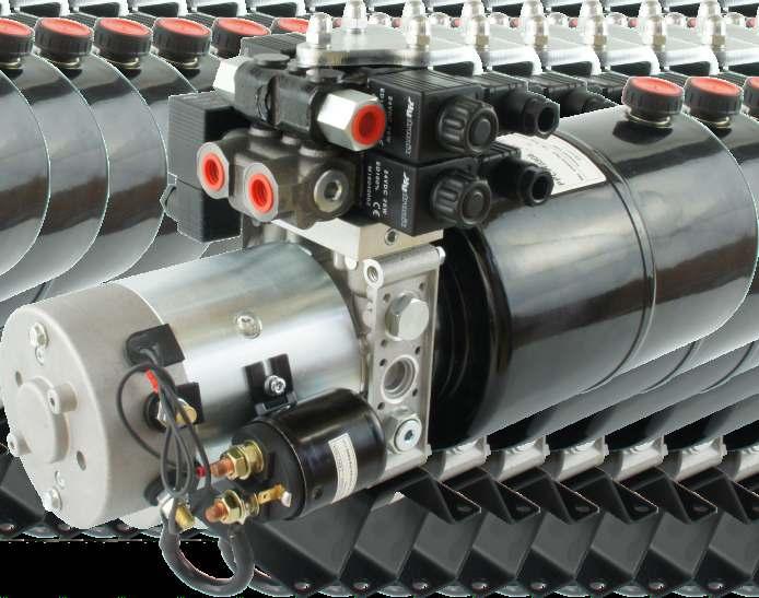
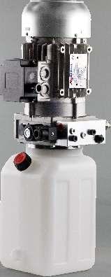
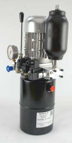
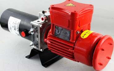
5 Hydronit hydraulic range hree main families: ower ack Micro, ower ack Compact, Electropumps ull sharing the most core components allowing mass production and stock optimization. Design, research & development according to flexibility, modularity and efficiency principles. C & DC MICRO hydraulic power packs Extremely compact and lightweight Flow:, ~ 6 l/min ressure up to 5 bar DC motors up to, kw C motors up to 1,8 kw High modularity: single & double acting & reversible circuits from the same micro central manifold Main valves on one side in most configurations for enhanced positioning in small machines C & DC COMC hydraulic power packs Over 1 years of serial production Hundred of thousands of power packs running worldwide Flow:, ~ 5 l/min Low pressure drop ressure up to 3 bar (or more in special application) DC motors up to 4 kw C motors up to 7,5 kw High modularity: single & double acting & reversible circuits from the same micro central manifold Ideal choice for hydraulic distributors & assemblers DC electropumps,15 ~ 4 kw, 1V e 4V DC motors (same used in Compact and Micro power packs) Forced ventilation for high cycle times,19 ~ 7,9 cc/rev gear pumps (same used in Compact and Micro power packs. vailable also lateral ports pumps) Option: relief valve, starter witch, thermal protection, foot mounting support
6 OWER CKS COMC speaking code C, 4DC_S U K1, J D_31 4DC R5 U X X X X ower ack Compact Electric motor or Mounting kit Central manifold Gear pump Cavity Cavity 1 Cavity Cavity 3 Cavity 4 Cav. 5 Cav. 6 Cav. 7 Cav. 8 DC Motors,15 1DC 1VDC 15W,15 4DC 4VDC 15W,3 1DC 1VDC 3W,3 4DC 4VDC 3W,5 1DC 1VDC 5W,5 4DC 4VDC 5W,8 1DC 1VDC 8W,8 4DC 4VDC 8W 1,6 1DC 1VDC 16W,1 1DC 1VDC 1W, 4DC 4VDC W 3 4DC 4VDC 3W 4 4DC 4VDC 4W,5HD 1DC 3HD 4DC 4HD 4DC DC Motors Options S _F _MC 1VDC 5W 4VDC 3W 4VDC 4W thermal switch starter switch fan cooler 1,6 4kW plastic cover C 3 hase Motors E,37C E,55C E,75C E1,1C 34 8 E1,5C 34 9 E,C 34 9 E3,C 34 9 E4,C 34 1 E5,5C 34 1 C Motors Mounting Kits,37kW S3 3 ph 4 poles,55kw S3 3 ph 4 poles,75kw S3 3 ph 4 poles 1,1kW S3 3 ph 4 poles 1,5kW S3 3 ph 4 poles,kw S3 3 ph 4 poles 3kW S3 3 ph 4 poles 4kW S3 3 ph 4 poles 5,5kW S3 3 ph 4 poles 14 7,5C ,5kW S3 3 ph 4 poles C Single hase Motors E,37C S4 71 E,55C S4 71 E,75C S4 8 E1,1C S4 9 E1,5C S4 9 E,C S4 9 E3,C S4 1,37kW S3 1 ph 4 poles,55kw S3 1 ph 4 poles,75kw S3 1 h 4 poles 1,1kW S3 1 ph 4 poles 1,5kW S3 1 ph 4 poles,kw S3 1 ph 4 poles 3kW S3 1 ph 4 poles X frame 71 + pump gr. X frame 8 + pump gr. X frame 71 + pump gr. 1 X frame 8 + pump gr. 1 X frame 8 + pump gr. 1 X frame 1/11 + p. gr. 1 X56C- Nema 56C + pump gr. X56C-1 Nema 56C + pump gr. 1 XU141- pulley + pump gr. XU141-1 pulley + pump gr. 1 Central Manifolds U U U4 UR Universal type with 3 lateral cavities Universal type with 5 lateral cavities Universal 4 type for 4 way cartridge valves Universal R type for reversible pump Central Manifolds Options US SE6 port for North merican market Gear umps K,,6 cc/rev gr K,4,38 cc/rev gr K,6,64 cc/rev gr K,9,89 cc/rev gr1 K1, 1,7 cc/rev gr1 K1,6 1,66 cc/rev gr1 K,1,17 cc/rev gr1 K,7,8 cc/rev gr1 K3, 3,3 cc/rev gr1 K3,7 3,8 cc/rev gr1 K4, 4,3 cc/rev gr1 K5, 5,1 cc/rev gr1 K6, 6, cc/rev gr1 K7,9 7,9 cc/rev gr1 G9,8 9,8 cc/rev gr1 Gear umps Options HL double pump with hi-lo circuit High ressure Gear umps H1, 1, cc/rev gr1 H1,7 1,7 cc/rev gr1 H,, cc/rev gr1 H,6,6 cc/rev gr1 H3, 3, cc/rev gr1 H3,8 3,8 cc/rev gr1 H4, 4,3 cc/rev gr1 H4,7 4,7 cc/rev gr1 H6, 6, cc/rev gr1 H7,4 7,4 cc/rev gr1 Cavity Valves J S L N Cavity options Cavity 1 Valves D_* X check valve 3/4-16UNF flow control valve plug 3/4-16UNF open plug with 1/4 S open port MIR63*EM* pressure gauge (*=bar max) +shut-off F41*W pressure switch (*=bar max) relief valve (*= bar max) closed plug for relief valve cavity Cavity and Cavity 4 Valves Q C D E EM Z S NC / way poppet valve NC / way poppet valve + emergency NO / way poppet valve NO / way poppet valve + emergency NC / way double poppet valve + emerg. lever operated / valve lever operated / with microswitch way emergency button flow control valve * proportional flow control valve (*=VDC) U hand pump cc/stroke G closed plug H closed plug with 1/4 S exit port N open plug with 1/4 S open port plug passing through 1/4 S exit port L plug 3/4-16UNF J check valve 3/4-16UNF Cavity Valves (U4 Central Manifolds) 4V11C 4/ way directional valve Low Noise Gear umps 4V 4/3 way directional valve, center to Standard mounting positioning 4V 4/3 way directional valve, closed center S,, cc/rev low N gr1 rules: 4VC 4/3 way directional valve, H center S3, 3, cc/rev low N gr1 Filler cap tank side ports and 4VE 4/3 way directional valve, center - to S4,3 4,3 cc/rev low N gr1 Electric box C motor side S6,4 6,4 cc/rev low N gr1 Cavity 3 Valves cavity S8,3 8,3 cc/rev low N gr1 R NC / way poppet valve reverse flow oles of DC motors and S1 1, cc/rev low N gr1 R NC / way poppet valve+em. reverse flow solenoid side cavity S13 1,9 cc/rev low N gr1 CR NO / way poppet valve+em. reverse flow For horizontal mounting units, D NC / way double poppet valve+emerg. suction filter side mounting foot Reversible Gear umps Z way emergency button holes R,3,3 cc/rev revers. gr R,5,49 cc/rev revers. gr F* fixed pressure comp. flow control (*=l/min) Lacking any specific requests R,7,64 cc/rev revers. gr R* pressure comp. flow control (*=l/min) by the customer, all power R,9,88 cc/rev revers. gr S flow control valve units are supplied assembled R1,3 1,5 cc/rev revers. gr * prop. relief valve + emergency (*= bar max) according with these rules. R1,5 1,54 cc/rev revers. gr V* relief valve (*= bar max) R,1,1 cc/rev revers. gr1 G closed plug R,6,6 cc/rev revers. gr1 H closed plug with 1/4 S exit port R3, 3, cc/rev revers. gr1 N open plug with 1/4 S open port R4,3 4,3 cc/rev revers. gr1 plug passing through 1/4 S exit port R6,5 6,5 cc/rev revers. gr1 L plug 3/4-16UNF his page contains only most J check valve 3/4-16UNF common codes and options. Solenoid Valves Coils 1DC 4DC 4C 115C 3C 1V direct current 4V direct current 4V alternate current 5 or 6Hz 115V alternate current 5 or 6Hz 3V alternate current 5 or 6Hz Cavity Valves 1(4) 1 l/min pres. comp. flow cont. ø 1,7 1,5(4) 1,5 l/min pres.comp.flow cont. ø1,7 (4) l/min pres. comp. flow cont. ø 1,7 3(4) 3 l/min pres. comp. flow cont. ø 1,7 5(4) 5 l/min pres. comp. flow cont. ø 1,7 7(4) 7 l/min pres. comp. flow cont. ø 1,7 1(4) 1 l/min pres.comp.flow cont. ø 1,7 13(4) 13 l/min pres.comp.flow cont. ø 1,7 17(4) 17 l/min pres.comp.flow cont. ø 1,7 (4) l/min pres.comp.flow cont. ø 1,7 1(1) 1 l/min 1/4 S p. comp. flow ctrl 1,5(1) 1,5 l/min 1/4 S p. comp. flow (1) l/min 1/4 S p. comp. flow ctrl 3(1) 3 l/min 1/4 S p. comp. flow ctrl 5(1) 5 l/min 1/4 S p. comp. flow ctrl 7(1) 7 l/min 1/4 S p. comp. flow ctrl 1(1) 1 l/min 1/4 S p. comp. flow ctrl 13(1) 13 l/min 1/4 S p. comp. flow ctrl 17(1) 17 l/min 1/4 S p. comp. flow ctrl (1) l/min 1/4 S p. comp. flow ctrl 1 1/4 S plug REURN-KI suction/return line pipe 137 RF1 suction/return line pipe return line immersed filter For the full available range please check following pages.
7 X 5V E6431 SD3 4DC E65436 Cavity 9 ank & mounting style External blocks External valves ccessories Cavity 9 Start up Under Load Valve S1C ~3l/min for 1ph C motor S1D 3~4l/min for 1ph C motor S1E 4~5,5l/min for 1ph C motor S1F 5,5~7l/min for 1ph C motor S1G 7~9l/min for 1ph C motor S1H 9~1,5l/min for 1ph C motor S1I 1,5~1,5l/min for 1ph C motor S1L 1,5~14l/min for 1ph C motor S1N 14~15,5l/min for 1ph C motor lastic anks 1,5L 1,5l square plastic 3L 3l square plastic 6L 6l square plastic 5M 5l square plastic 8M 8l square plastic 5 5l round plastic 7 7l round plastic 9 9l round plastic 11 11l round plastic Steel anks 1,5 1,5l cylindrical steel,5,5l cylindrical steel 5 5l cylindrical steel 1 1l cylindrical steel 1 1l cylindrical steel 1C 1l square steel C l square steel 3EV 3l square steel 7EV 7l square steel 8EV 8l square steel 15EV 15l square steel EV l square steel 3EV 3l square steel F81 steel tank adapter anks Options V vertical mounting External locks NG3 M M6434 3mm spacer subplate M rotation manifold M6431 Ng3 MICRO parallel block lateral ports M64131 Ng3 MICRO manifold with p.o. check v. External locks NG6 (cetop3) C E6434 8mm spacer subplate E643 49mm 9 rotation manifold E6435DF 9 rotation manifold double face E64339 additional single acting manifold E6431 Ng6 (Cetop3) parallel block rear ports E6431 Ng6 (Cetop3) parallel block lateral ports E64311 Ng6 (Cetop3) series block lateral ports E64131 Ng6 (Cetop3) manifold with p.o. check v. E643 spin-on return line filter block E6435 filter in pressure block M4 hand pump 4 cc/stroke manifold block M9 hand pump 8,8 cc/stroke manifold block E6433 SE8 -way cartridge manifold block E64331 SE8 3-way cartridge manifold block locks Options /US SE6 exit ports for North merican market iastre Di dattamento E6436 adapter C-SD1 E6436DN adapter C-SD E6438M adapter C-M ccessories MIR636EM pressure gauge 6bar + shut-off MIR6316EM pressure gauge 16bar + shut-off MIR635EM pressure gauge 5bar + shut-off MIR63315EM pressure gauge 315bar + shut-off F415W pressure switch 5-5bar F411W pressure switch 1-1bar F41W pressure switch -bar F414W pressure switch 5-4bar 1 remote buttons control box remote 4 buttons control box VC WM driver for proportional valves E65436 foot mounting support E65437 foot mounting support - tall type VUR1C in-line check valve 1/4 S VURC in-line check valve 3/8 S VURSE6C in-line check valve 9/16-18UNF SU1 in-line unidirectional flow valve 1/4 S SU in-line unidirectional flow valve 3/8 S SUSE6 in-line unidirectional flow valve 9/16-18UNF S1 in-line bidirectional flow valve 1/4 S S in-line bidirectional flow valve 3/8 S SSE6 in-line bidirectional flow valve 9/16-18UNF FCSE81 In-line mounting SE8 manifold 1/4 S FCSE8 In-line mounting SE8 manifold 3/8 S Solenoid Directional Valves SD11C NG3 MICRO directional valve 4/ SD SD SDC SDE NG3 MICRO directional valve 4/3 center to NG3 MICRO directional valve 4/3 closed center NG3 MICRO directional valve 4/3 H center Ng3 MICRO directional valve 4/3 center - to SD111C Stackable directional valve 4/ SD1 SD1 SD1C Stackable directional valve 4/3 to Stackable directional valve 4/3 closed center Stackable directional valve 4/3 H center SD1E Stackable directional valve 4/3 center - to SDCR Stackable dir. valve 4/3 H center + p.o. check valves SDER Stackable dir. valve4/3center - to + p.o. check valves SD Stackable dir. valve 4/3 to + cavity SE8 SD St ackable dir. valve 4/3 closed center + cavity SE8 SDC Stackable dir. valve 4/3 H center + cavity SE8 SDE Stackable dir. valve 4/3 - to + cavity SE8 SD311C NG6 (cetop 3) directional valve 4/ SD3 SD3 SD3C SD3E NG6 (cetop 3) directional valve 4/3 center to NG6 (cetop3) directional valve 4/3 closed center NG6 (cetop3) directional valve 4/3 H center NG6 (cetop3) directional valve 4/3 center - to Solenoid Directional Valves Coils 1DC 4DC 4C 115C 3C Note: not all the voltages are available on some valve codes Hand Operated Directional Valves HD31 HD3 HD33 HD31 HD3D1 HD3D HD3D3 HD3D1 1V direct current 4V direct current 4V alternate current 5 or 6Hz 115V alternate current 5 or 6Hz 3V alternate current 5 or 6Hz NG6 (cetop3) manual dir. valve spring centered, to NG6 (cetop3) manual dir. v. spring centered closed center NG6 (cetop3) manual dir. valve spring centered, H center NG6 (cetop3) manual dir. valve spring centered, - to NG6 (cetop3) manual dir. valve with detent, to NG6 (cetop3) manual dir. valve with detent, closed center NG6 (cetop3) manual dir. valve with detent, H center NG6 (cetop3) manual dir. v. with detent, center - to Sandwich Modular Valves E6431 NG6 (cetop3) sandwich modular valve with relief valves E64331 NG6 (cetop3) sandwich modular valve with throttle valves Reference hydraulic scheme U central manifold (see section for all central manifolds executions) M 5 8


 and in the")


, in the")

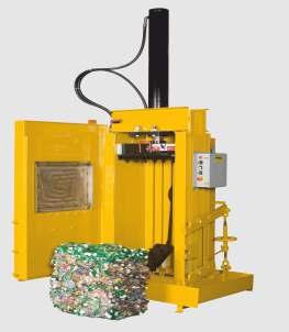
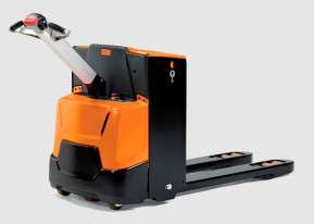


8 Some typical applications he high level of modularity and circuit flexibility of Hydronit hydraulic power packs and electropumps allows you to use them in the most varied applications: in addition to typical applications of lifting equipment and hydraulic vehicles (dump trucks, tail lifts,...) and in the industrial (presses, machine tools, hoists, hydraulic brakes,...), even in the automotive industry (drive doors and hood, suspension, campervan...), marine (bridges, cranes, doors,...), in the alternative energy sector, in agricultural equipment, in the field of construction machinery, in elevator equipment, in explosions proof environments. Hydronit has also developed solutions for improvement to equipment previously available on the market, including the use of proportional components and electronics for forklift trucks, snow plows, brake and transmission equipment, loading ramps. DC applications C applications


 E,37C 34 71 integral motor,37kw S3 3-ph 4-pole /38V")

 E,37C S4 71 integral motor,37kw S3 1-ph 4-pole V 5Hz frame 71 E,55C S4 71 integral motor,55kw S3 1-ph 4-pole V 5Hz frame 71 E,75C S4 8 integral")

9 INDEX C & DC electric motors Section DC motors,15 1DC_ 1VDC motor - 15W - Ø 8 + thermal switch,15 4DC_ 4VDC motor - 15W - Ø 8 + thermal switch,3 1DC_ 1VDC motor - 3W - Ø 8 + thermal switch,3 4DC_ 4VDC motor - 3W - Ø 8 + thermal switch,5 1DC 1VDC motor - 5W - Ø 8,5 4DC 4VDC motor - 5W - Ø 8,5 1DC_ 1VDC motor - 5W - Ø 8 + thermal switch,5 4DC_ 4VDC motor - 5W - Ø 8 + thermal switch,8 1DC 1VDC motor - 8W - Ø 8,8 4DC 4VDC motor - 8W - Ø 8,8 1DC_ 1VDC motor - 8W - Ø 8 + thermal switch,8 4DC_ 4VDC motor - 8W - Ø 8 + thermal switch 1,6 1DC_ 1VDC motor - 16W - Ø thermal switch,1 1DC_ 1VDC motor - 1W - Ø thermal switch, 4DC_ 4VDC motor - W - Ø thermal switch 3 4DC_ 4VDC motor - 3W - Ø 15 + thermal switch 4 4DC_ 4VDC motor - 4W - Ø 15 + thermal switch,5hd 1DC_ 1VDC motor - 5W - Ø 151 fan cooled 14-9 frame + thermal switch 3HD 4DC_ 4VDC motor - 3W - Ø 151 fan cooled 14-9 frame + thermal switch 4HD 4DC_ 4VDC motor - 4W - Ø 151 fan cooled 14-9 frame + thermal switch C motors: three-phase 4 poles (~145 5Hz / ~175 6Hz) E,37C integral motor,37kw S3 3-ph 4-pole /38V 5/6Hz frame 71 E,55C integral motor,55kw S3 3-ph 4-pole /38V 5/6Hz frame 71 E,75C integral motor,75kw S3 3-ph 4-pole /38V 5/6Hz frame 71 E1,1C 34 8 integral motor 1,1kW S3 3-ph 4-pole /38V 5/6Hz frame 8 E1,5C 34 9 integral motor 1,5kW S3 3-ph 4-pole /38V 5/6Hz frame 9 E,C 34 9 integral motor,kw S3 3-ph 4-pole /38V 5/6Hz frame 9 E3,C 34 9 integral motor 3kW S3 3-ph 4-pole /38V 5/6Hz frame 9 E4,C 34 1 integral motor 4kW S3 3-ph 4-pole /38V 5/6Hz frame 1 E5,5C 34 1 integral motor 5,5kW S3 3-ph 4-pole /38V 5/6Hz frame 1 C motors: single-phase 4 poles (~145 5Hz) E,37C S4 71 integral motor,37kw S3 1-ph 4-pole V 5Hz frame 71 E,55C S4 71 integral motor,55kw S3 1-ph 4-pole V 5Hz frame 71 E,75C S4 8 integral motor,75kw S3 1-ph 4-pole V 5Hz frame 71 E1,1C S4 9 integral motor 1,1kW S3 1-ph 4-pole V 5Hz frame 9 E1,5C S4 9 integral motor 1,5kW S3 1-ph 4-pole V 5Hz frame 9 E,C S4 9 integral motor,kw S3 1-ph 4-pole V 5Hz frame 9 E3,C S4 1 integral motor 3kW S3 1-ph 4-pole V 5Hz frame 9 pole and special execution motors (High starting torque, high I, with thermal protector,...) available on request C14/1-1


 U U U4 UR Universal type C body with 3")

10 INDEX C & DC electric motors 14 C motors 14 7,5C motor 7,5kW S3 3-ph -poles /38V 5/6Hz frame ,5C motor 5,5kW S3 3-ph 4-poles /38V 5/6Hz frame 11 No motor: 14 Flange + coupling kit X mounting kit C for 14 motors frame 71 with pump group X14 8- mounting kit C for 14 motors frame 8 with pump group X mounting kit C for 14 motors frame 71 with pump group 1 X mounting kit C for 14 motors frame 8 with pump group 1 X mounting kit C for 14 motors frame 9 with pump group 1 X mounting kit C for 14 motors frame 1/11 with pump group 1 X56C- mounting kit C for Nema 56C-face motors with pump group X56C-1 mounting kit C for Nema 56C-face motors with pump group 1 XU141- kit drag pulley C with pump group XU141-1 kit drag pulley C with pump group 1 Electric motors options DC motors options S15 1DC 8 S15 4DC 8 R1 1DC 8 R1 4DC 8 starting relay 1VDC 15 with mounting kit for Ø 8 motors starting relay 4VDC 15 with mounting kit for Ø 8 motors starting relay with reverse gear 1VDC 1 starting relay with reverse gear 4VDC 1 S15 1DC 11 starting relay 1VDC 15 with mounting kit for Ø motors S15 4DC 11 starting relay 4VDC 15 with mounting kit for Ø motors S 1DC 15_151 starting relay 1VDC with mounting kit for Ø motors S 4DC 15_151 starting relay 4VDC with mounting kit for Ø motors F forced ventilation system for motors Ø 114 and Ø 15 MC plastic protection for motor protection DC Ø Universal central manifold Section International execution (1/4" S exit ports) U U U4 UR Universal type C body with 3 lateral cavities Universal type C body with 5 lateral cavities Universal 4 type C body for 4 way cartridge valves Universal R type C body for reversible pump US execution (SE 6 exit ports) UUS UUS U4US URUS Universal type C body with 3 lateral cavities US execution Universal type C body with 5 lateral cavities US execution Universal 4 type C body for 4 way cartridge valves US execution Universal R type C body for reversible pump US execution C14/1-


11 INDEX Gear pumps Section C G,1 gear pump group,19 cc/rev G series + adaptor flange for group pump G, gear pump group,6 cc/rev G series + adaptor flange for group pump G,4 gear pump group,38 cc/rev G series + adaptor flange for group pump G,6 gear pump group,64 cc/rev G series + adaptor flange for group pump G,8 gear pump group 1,85 cc/rev G series G1,1 gear pump group 1 1,15 cc/rev G series G1,3 gear pump group 1 1,3 cc/rev G series G1,6 gear pump group 1 1,6 cc/rev G series G,1 gear pump group 1,1 cc/rev G series G,6 gear pump group 1,6 cc/rev G series G3, gear pump group 1 3, cc/rev G series G3,7 gear pump group 1 3,7 cc/rev G series G4, gear pump group 1 4, cc/rev G series G4,9 gear pump group 1 4,9 cc/rev G series G6, gear pump group 1 6, cc/rev G series G7,9 gear pump group 1 7,9 cc/rev G series G9,8 gear pump group 1 9,8 cc/rev G series K, gear pump group,6 cc/rev K series + adaptor flange for group pump K,4 gear pump group,38 cc/rev K series + adaptor flange for group pump K,6 gear pump group,64 cc/rev K series + adaptor flange for group pump K,9 gear pump group 1,89 cc/rev K series K1, gear pump group 1 1,7 cc/rev K series K1,6 gear pump group 1 1,66 cc/rev K series K,1 gear pump group 1,17 cc/rev K series K,7 gear pump group 1,8 cc/rev K series K3, gear pump group 1 3,3 cc/rev K series K3,7 gear pump group 1 3,8 cc/rev K series K4, gear pump group 1 4,3 cc/rev K series K5, gear pump group 1 5,1 cc/rev K series K6, gear pump group 1 6, cc/rev K series K7,9 gear pump group 1 7,9 cc/rev K series H1, gear pump group 1 high pressure 1, cc/rev H series H1,7 gear pump group 1 high pressure 1,7 cc/rev H series H, gear pump group 1 high pressure, cc/rev H series H,6 gear pump group 1 high pressure,6 cc/rev H series H3, gear pump group 1 high pressure 3, cc/rev H series H3,8 gear pump group 1 high pressure 3,8 cc/rev H series H4, gear pump group 1 high pressure 4,3 cc/rev H series H4,7 gear pump group 1 high pressure 4,7 cc/rev H series H6, gear pump group 1 high pressure 6, cc/rev H series H7,4 gear pump group 1 high pressure 7,4 cc/rev H series C14/1-3


 + EM9 pressure gauge Ø63 where *** = max (6-16-5-315 bar) + EMIL pressure switch 1/4 S where *** = max (5-1--4 bar)")
12 INDEX Gear pumps idirectional gear pumps R,3 Reversible gear pump group -,3 cc/rev R series + adaptor flange for group pump R,5 Reversible gear pump group -,49 cc/rev R series + adaptor flange for group pump R,7 Reversible gear pump group -,64 cc/rev R series + adaptor flange for group pump R,9 Reversible gear pump group -,88 cc/rev R series + adaptor flange for group pump R1,3 Reversible gear pump group - 1,5 cc/rev R series + adaptor flange for group pump R1,5 Reversible gear pump group - 1,54 cc/rev R series + adaptor flange for group pump R,1 Reversible gear pump group 1 -, cc/rev R series R,6 Reversible gear pump group 1 -,6 cc/rev R series R3, Reversible gear pump group 1-3, cc/rev R series R4,3 Reversible gear pump group 1-4,3 cc/rev R series R6,5 Reversible gear pump group 1-6,5 cc/rev R series Double gear pumps with Hi-Lo system K,9+3,HL K1,+5HL HI-LO double pump -,9 + 3,3cc/rev K series HI-LO double pump - 1, + 5cc/rev K series Helical rotor pumps for high pressure and low noise and low pulsation applications S, low noise helical rotor pump group 1 -, cc/rev S series S3, low noise helical rotor pump group 1-3, cc/rev S series S4,3 low noise helical rotor pump group 1-4,3 cc/rev S series S5, low noise helical rotor pump group 1-5, cc/rev S series S6,4 low noise helical rotor pump group 1-6,4 cc/rev S series S8,3 low noise helical rotor pump group 1-8,3 cc/rev S series S1 low noise helical rotor pump group 1-1, cc/rev S series S13 low noise helical rotor pump group 1-1,9 cc/rev S series Integral components: Cavity Components in central manifold cavity Section D J JF S L N check valve ball type 3/4-16UNF check valve ball type 3/4-16UNF with exit port static F 1/4 S flow control valve 3/4-16UNF with screw plug 3/4-16UNF basic plug 3/4-16UNF open passage with 1/4 S exit port Cavity option 1 EM9 EMIL MIR63***EM9 MIR63***EMIL F41***W V-CS plug CE 1/4 S with copper washer pressure gauge shut-off valve 9 F-F spinning + nipples M-M 1/4 S pressure gauge shut-off valve F-F spinning + nipples M-M 1/4 S pressure gauge Ø63 where *** = max ( bar) + EM9 pressure gauge Ø63 where *** = max ( bar) + EMIL pressure switch 1/4 S where *** = max ( bar) handwheel for CS C14/1-4


 4/3 way solenoid directional valve, center to (only for cavity in U4 manifolds) 4/3 way solenoid directional valve, closed center")
 Cavity and 4 options V-CS 1 EM9 EMIL MIR63***EM9 MIR63***EMIL F41***W VC handwheel for CS")
 + EM9 pressure gauge Ø63 where *** = max (6-16-5-315 bar) + EMIL pressure")
13 INDEX Integral components: Cavity 1 Components in central manifold cavity 1 D_6 D_18 D_31 X guided needle relief valve Mx1,5-5 6 bar - socket screw adj. guided needle relief valve Mx1, bar - socket screw adj. guided needle relief valve Mx1, bar - socket screw adj. closed plug for relief valve Mx1,5 cavity Cavity 1 option handwheel M8 for valves VMDC35/VMDC/VCF6 3 steel cap for valve VMDC35 4 plastic seal for VMDC35 relief valve Integral components: Cavity and Cavity 4 Components in central manifold cavity and cavity 4 Q C D E EM Z S 1DC 4DC U G H N L J 4V11C 4V 4V 4VC 4VE NC solenoid / way 3/4-16UNF poppet valve NC solenoid / way 3/4-16UNF poppet valve with emergency NO solenoid / way 3/4-16UNF poppet valve NO solenoid / way 3/4-16UNF poppet valve with emergency NC solenoid / way 3/4-16UNF double poppet valve with emergency lever operated / way valve without micro-switch lever operated / way valve with micro-switch way emergency button valve bidirectional flow control valve 3/4-16UNF with screw proportional flow control valve poppet type 15l/min 315 bar + coil 1VDC ED1% proportional flow control valve poppet type 15l/min 315 bar + coil 4VDC ED1% hand pump 3/4-16UNF cc/stroke + suction/return line pipe 1/4 S 37mm closed plug 3/4-16UNF plug 3/4-16UNF with 1/4 S exit port plug 3/4-16UNF open passage with 1/4 S exit port plug 3/4-16UNF passing through 1/4 S plug 3/4-16UNF basic check valve ball type 3/4-16UNF 4/way solenoid directional valve, closed center transient (only for cav. in U4manifolds) 4/3 way solenoid directional valve, center to (only for cavity in U4 manifolds) 4/3 way solenoid directional valve, closed center (only for cavity in U4 manifolds) 4/3 way solenoid directional valve, H center (only for cavity in U4 manifolds) 4/3 way solenoid directional valve, center - to (only for cavity in U4 manifolds) Cavity and 4 options V-CS 1 EM9 EMIL MIR63***EM9 MIR63***EMIL F41***W VC handwheel for CS plug CE 1/4 S with copper washer pressure gauge shut-off valve 9 F-F spinning + nipples M-M 1/4 S pressure gauge shut-off valve F-F spinning + nipples M-M 1/4 S pressure gauge Ø63 where *** = max ( bar) + EM9 pressure gauge Ø63 where *** = max ( bar) + EMIL pressure switch 1/4 S where *** = max ( bar) WM driver for proportional valves 1/4VDC C14/1-5


14 INDEX Integral components: Cavity 3 Components in central manifold cavity 3 F1 fixed pressure compensated flow control valve 3/4-16UNF flow - 1l/min F1,5 fixed pressure compensated flow control valve 3/4-16UNF flow - 1,5l/min F fixed pressure compensated flow control valve 3/4-16UNF flow - l/min F3 fixed pressure compensated flow control valve 3/4-16UNF flow - 3l/min F5 fixed pressure compensated flow control valve 3/4-16UNF flow - 5l/min F7 fixed pressure compensated flow control valve 3/4-16UNF flow - 7l/min F1 fixed pressure compensated flow control valve 3/4-16UNF flow - 1l/min F13 fixed pressure compensated flow control valve 3/4-16UNF flow - 13l/min F17 fixed pressure compensated flow control valve 3/4-16UNF flow - 17l/min F fixed pressure compensated flow control valve 3/4-16UNF flow - l/min R compensated flow control valve 3/4-16UNF with screw - 1, l/min R3 compensated flow control valve 3/4-16UNF with screw - 1,6 4 l/min R4 compensated flow control valve 3/4-16UNF with screw -,5 5 l/min R5 compensated flow control valve 3/4-16UNF with screw l/min R6 compensated flow control valve 3/4-16UNF with screw - 4,9 1,8 l/min R7 compensated flow control valve 3/4-16UNF with screw ,5 l/min S flow control valve 3/4-16UNF with screw Z way emergency button valve R NC solenoid / way 3/4-16UNF poppet valve with reversible flow R NC solenoid / way 3/4-16UNF poppet valve +emergency with reversible flow CR NO solenoid / way 3/4-16UNF poppet valve +emergency with reversible flow D NC solenoid / way 3/4-16UNF double poppet valve with emergency J check valve ball type 3/4-16UNF G closed plug 3/4-16UNF H plug 3/4-16UNF with 1/4 S exit port N plug 3/4-16UNF open passage with 1/4 S exit port plug 3/4-16UNF passing through 1/4 S L basic plug 3/4-16UNF ***1DC prop. relief valve 3/4-16UNF with em. 1VDC where *** = max pressure (8-5 bar) ***4DC prop. relief valve 3/4-16UNF with em. 4VDC where *** = max pressure (8-5 bar) V*** relief valve 3/4-16UNF where ** = max pressure ( bar) - socket screw Cavity 3 option handwheel M8 for valves VMDC35/VMDC/VCF6 V-CS handwheel for CS 1 plug CE 1/4 S with copper wahser EM9 EMIL MIR63***EM9 MIR63***EMIL F41***W VC pressure gauge shut-off valve 9 F-F spinning + nipples M-M 1/4 S pressure gauge shut-off valve F-F spinning + nipples M-M 1/4 S pressure gauge Ø63 where *** = max ( bar) + EM9 pressure gauge Ø63 where *** = max ( bar) + EMIL pressure switch 1/4 S where *** = max ( bar) WM driver for proportional valves 1/4VDC C14/1-6
 fixed pressure compensated flow control valve")
15 INDEX Integral components: Cavity 5, Cavity 6 and Cavity 8 Components in central manifold cavity 5, cavity 6 and cavity 8 1 1/4 S plug with copper washer 137 suction/return line pipe 1/4 S 37mm REURN-KI 1/4 S holder for SF1 + flexible plastic pipe 1 mm for return line / price per meter RF1 return line tank immersed filter + drain pipe 1/4 S 1(1) fixed pressure compensated flow control valve 1/4"S - 1l/min 1,5(1) fixed pressure compensated flow control valve 1/4"S - 1,5l/min (1) fixed pressure compensated flow control valve 1/4"S - l/min 3(1) fixed pressure compensated flow control valve 1/4"S - 3l/min 5(1) fixed pressure compensated flow control valve 1/4"S - 5l/min 7(1) fixed pressure compensated flow control valve 1/4"S - 7l/min 1(1) fixed pressure compensated flow control valve 1/4"S - 1l/min 13(1) fixed pressure compensated flow control valve 1/4"S - 13l/min 17(1) fixed pressure compensated flow control valve 1/4"S - 17l/min (1) fixed pressure compensated flow control valve 1/4"S - l/min Integral components: Cavity 7 Components in central manifold cavity 7 1(4) fixed pressure compensated flow control valve Ø 1,7 con o-ring - 1l/min 1,5(4) fixed pressure compensated flow control valve Ø 1,7 con o-ring - 1,5l/min (4) fixed pressure compensated flow control valve Ø 1,7 con o-ring - l/min 3(4) fixed pressure compensated flow control valve Ø 1,7 con o-ring - 3l/min 5(4) fixed pressure compensated flow control valve Ø 1,7 con o-ring - 5l/min 7(4) fixed pressure compensated flow control valve Ø 1,7 con o-ring - 7l/min 1(4) fixed pressure compensated flow control valve Ø 1,7 con o-ring - 1l/min 13(4) fixed pressure compensated flow control valve Ø 1,7 con o-ring - 13l/min 17(4) fixed pressure compensated flow control valve Ø 1,7 con o-ring - 17l/min (4) fixed pressure compensated flow control valve Ø 1,7 con o-ring - l/min Integral components: Cavity 9 Components in central manifold cavity 9 S1C S1D S1E S1F S1G S1H S1I S1L S1N starting valve for single-phase motors for flow from to 3 lt/min starting valve for single-phase motors for flow from 3 to 4 lt/min starting valve for single-phase motors for flow from 4 to 5,5 lt/min starting valve for single-phase motors for flow from 5,5 to 7 lt/min starting valve for single-phase motors for flow from 7 to 9 lt/min starting valve for single-phase motors for flow from 9 to 1,5 lt/min starting valve for single-phase motors for flow from 1,5 to 1,5 lt/min starting valve for single-phase motors for flow from 1,5 to 14 lt/min starting valve for single-phase motors for flow from 14 to 15,5 lt/min C14/1-7


16 INDEX anks Serbatoio in metallo Section E 1,5 1,5l cylindrical steel tank horizontal mounting + 1/"S std filler & breather plug 1,5V 1,5l cylindrical steel tank vertical mounting + 1/"S std filler & breather plug,5,5l cylindrical steel tank horizontal mounting + 1/"S std filler & breather plug,5v,5l cylindrical steel tank vertical mounting + 1/"S std filler & breather plug 5 5l cylindrical steel tank horizontal mounting + 1/"S std filler & breather plug 5V 5l cylindrical steel tank vertical mounting + 1/"S std filler & breather plug 1 1l cylindrical steel tank horizontal mounting + 1/"S std filler & breather plug 1V 1l cylindrical steel tank vertical mounting + 1/"S std filler & breather plug 1 1l cylindrical steel tank horizontal mounting + 1/"S std filler & breather plug 1V 1l cylindrical steel tank vertical mounting + 1/"S std filler & breather plug 1C 1l square steel tank horizontal mounting + 1/"S std filler & breather plug 1CV 1l square steel tank vertical mounting + 1/"S std filler & breather plug C l square steel tank horizontal mounting + 3/4"S std filler & breather plug CV l square steel tank vertical mounting + 3/4"S std filler & breather plug 3EV 3l square steel tank vertical mounting + 1/"S std filler & breather plug 7EV 7l square steel tank vertical mounting + 1/"S std filler & breather plug 8EV 8l square steel tank vertical mounting + 3/4"S std filler & breather plug 15EV 15l square steel tank vertical mounting + 3/4"S std filler & breather plug EV l square steel tank vertical mounting + 3/4"S std filler & breather plug and level 3EV 3l square steel tank vertical mounting + 3/4"S std filler & breather plug and level F81 steel tank adapter for C - to be welded on custom made tanks lastic tanks 1,5L 1,5l square plastic tank type L horizontal mounting + 3/4"S F filler & breather plug 1,5LV 1,5l square plastic tank type L vertical mounting + 3/4 S F filler & breather plug 3L 3l square plastic tank type L horizontal mounting + 3/4"S F filler & breather plug 3LV 3l square plastic tank type L vertical mounting + 3/4 S F filler & breather plug 6L 6l square plastic tank type L horizontal mounting + 3/4 S F filler & breather plug 6LV 6l square plastic tank type L vertical mounting + 3/4 S F filler & breather plug 5M 5l square plastic tank 17mm type M horizontal mounting + 3/4 S F filler & breather 5MV 5l square plastic tank 17mm type M vertical mounting + 3/4 S F filler & breather 8M 8l square plastic tank 17mm type M horizontal mounting + 3/4 S F filler & breather 8MV 8l square plastic tank 17mm type M vertical mounting + 3/4 S F filler & breather 5 5l round plastic tank for C Ø195mm horizontal mounting + 1/"S filler & breather 5V 5l round plastic tank for C Ø195mm vertical mounting + 1/"S filler & breather 7 7l round plastic tank for C Ø195mm horizontal mounting + 1/"S filler & breather 7V 7l round plastic tank for C Ø195mm vertical mounting + 1/"S filler & breather 9 9l round plastic tank for C Ø195mm horizontal mounting + 1/"S filler & breather 9V 9l round plastic tank for C Ø195mm vertical mounting + 1/"S filler & breather 11 11l round plastic tank for C Ø195mm horizontal mounting + 1/"S filler & breather 11V 11l round plastic tank for C Ø195mm vertical mounting + 1/"S filler & breather C14/1-8

 + EMIL pressure switch 1/4 S where *** = max (5-1--4 bar)")


 External blocks External blocks E6434 E643 E6435DF E6431 E6431 E64311 E6413 E64131 E64133 E6437 E6438")
 parallel block - 3/8 S rear ports NG6")
 manifold with piloted check valve on and NG6 (cetop 3) manifold with")

 C to SD converter")


17 INDEX ccessories Section F ccessories E65436 E65437 EM9 EMIL MIR63***EM9 MIR63***EMIL F41***W F4RM3 MIR41 DE44 DV44 foot mounting h 47 mm foot mounting h 67 mm pressure gauge shut-off valve 9 F-F spinning + nipples M-M 1/4 S pressure gauge shut-off valve F-F spinning + nipples M-M 1/4 S pressure gauge Ø63 where *** = max ( bar) + EM9 pressure gauge Ø63 where *** = max ( bar) + EMIL pressure switch 1/4 S where *** = max ( bar) pressure switch 1/8 S,-,5bar for filter manifold E643 pressure gauge Ø4 1bar max for filter manifold E643 differential pressure switch electric 1/ S to block filter under pressure - 4 bar differential pressure switch visual 1/ S to block filter under pressure - 4 bar 1 remote up/down control with 3m flying cable for single/double acting cylinder remote 4 buttons control with 3m flying cable for double acting cylinders ORMF1 port 1/4 S F for modular blocks FCSE8* in-line manifold SE8 3/4-16UNF way M***C in-line manifold for modular blocks + relief valve, where ***= max (1-5bar) External blocks External blocks E6434 E643 E6435DF E6431 E6431 E64311 E6413 E64131 E64133 E6437 E6438 E643 E6435 M4 M9 E6436 E6436DN E6438M M6431 M6434 M6435 M6413 M64131 M64133 E6433 E64331 E mm spacer subplate 9 rotation manifold 49 mm 9 rotation manifold double face 79 mm NG6 (cetop 3) parallel block - 3/8 S rear ports NG6 (cetop 3) parallel block - 3/8 S lateral ORS NG6 (cetop 3) series block - 3/8 S lateral ports NG6 (cetop 3) manifold with piloted check valve on NG6 (cetop 3) manifold with piloted check valve on and NG6 (cetop 3) manifold with piloted check valve on modular manifold with piloted check valves on and modular manifold with check valve for differential area cylinder modular basic manifold for spin-on return filter on line modular basic manifold for spin-on pressure filter on line hand pump 4, cc/stroke cartridge only + base modular manifold hand pump 8,8 cc/stroke cartridge only + base modular manifold C to SD1 converter (needed to mount SD1 stackable valves) C to SD converter (needed to mount SD stackable valves) C to M base converter (needed to mount SD NG3 MICRO valves) M NG3 MICRO modular manifold with 1/4" S lateral ports M spacer element 3 mm M 9 rotation manifold 39,5 mm M NG3 MICRO modular manifold with piloted check valves on M NG3 MICRO modular manifold with piloted check valves on and M NG3 MICRO modular manifold with piloted check valves on manifold for MSV or MDV / way cartridge valves manifold for MSV3V 3/ way cartridge valve manifold simple circuit additive effect C14/1-9


18 INDEX External valves Section G Valvole esterne MSV3V4 MSV3 MSV3E MSV31 MSV31E MDV3E SD11C SD SD SDC SDE SD111C SD1 SD1 SD1C SD1E SD111CC SD1C SD1C SD1CC SD1EC SD11C SD SD SDC SDE SDCR SDER SD11C 3/ way solenoid cartridge valve, to de-energized NC solenoid / way 3/4-16UNF poppet valve NC solenoid / way 3/4-16UNF poppet valve with emergency NO solenoid / way 3/4-16UNF poppet valve NO solenoid / way 3/4-16UNF poppet valve with emergency NC solenoid / way 3/4-16UNF double poppet valve with emergency NG3 MICRO solenoid directional valve 4 way, positions NG3 MICRO solenoid directional valve 4 way, 3 pos. center to NG3 MICRO solenoid directional valve 4 way, 3 pos. closed center NG3 MICRO solenoid directional valve 4 way, 3 pos. H center NG3 MICRO solenoid directional valve 4 way, 3 pos. center - to Stackable solenoid directional valve 4 way, positions Stackable solenoid directional valve 4 way, 3 pos. center to Stackable solenoid directional valve 4 way, 3 pos. closed center Stackable solenoid directional valve 4 way, 3 pos. H center Stackable solenoid directional valve 4 way, 3 pos. center - to Stackable solenoid directional valve 4 way, positions - upper closing element Stackable solenoid directional valve 4 way, 3 pos. center to - upper closing element Stackable solenoid directional valve 4 way, 3 pos. closed center - upper closing element Stackable solenoid directional valve 4 way, 3 pos. H center - upper closing element Stackable solenoid directional valve 4 way, 3 pos. H center - upper closing element Stackable solenoid directional valve 4 way, positions lateral ports Stackable solenoid directional valve 4 way, 3 pos. center to lateral ports Stackable solenoid directional valve 4 way, 3 pos. closed center lateral ports Stackable solenoid directional valve 4 way, 3 pos. H center lateral ports Stackable solenoid directional valve 4 way, 3 pos. center - to lateral ports Stackable solenoid directional valve 4 way, 3 pos. H center + piloted check valves Stackable solenoid directional valve 4 way, 3 pos. center - to + piloted check valves Stackable solenoid directional valve 4 way, pos. + cavity 3/4-16UNF for add valves SD Stack. solenoid direct. valve 4 way,3 pos.center to +cavity 3/4-16UNF for add valves SD Stack. solenoid direct. valve 4 way,3 pos.closed center + cavity3/4-16unf for add valves SDC Stack. solenoid direct. valve 4 way,3 pos. H center + cavity 3/4-16UNF for add valves SDE Stack. solenoid direct. valve 4 way,3 pos. center -to+cavity3/4-16unf for add valves SD311C NG6 (cetop3) solenoid directional valve 4 way, positions SD3 NG6 (cetop3) solenoid directional valve 4 way, 3 pos. center to SD3 NG6 (cetop3) solenoid directional valve 4 way, 3 pos. closed center SD3C NG6 (cetop3) solenoid directional valve 4 way, 3 pos. H CENER SD3E NG6 (cetop3) solenoid directional valve 4 way, 3 pos. center - to HD31 NG6 (cetop3) manual directional valve, spring centered to HD3 NG6 (cetop3) manual directional valve, spring centered closed center HD33 NG6 (cetop3) manual directional valve, spring centered H center HD31 NG6 (cetop3) manual directional valve, spring centered - to HD3D1 NG6 (cetop3) manual directional valve, detent, center to HD3D NG6 (cetop3) manual directional valve, detent, closed center HD3D3 NG6 (cetop3) manual directional valve, detent, H center HD3D1 NG6 (cetop3) manual directional valve, detent, center - to C14/1-1
 sandwich type modular valve with relief valve on & 18bar max NG6 (cetop3) sandwich type modular valve with relief valve on & 31bar max NG6 (cetop3) sandwich type modular valve with relief")
 sandwich type modular valve with unidirectional throttle valve on & NG6 (cetop3) sandwich type modular valve with")


19 INDEX External valves External valves E6431L E6431 E6431 E643L E643 E643 E6433L E6433 E6433 E6433 E64331 E6433 E64333 NG6 (cetop3) sandwich type modular valve with relief valve on & 6bar max NG6 (cetop3) sandwich type modular valve with relief valve on & 18bar max NG6 (cetop3) sandwich type modular valve with relief valve on & 31bar max NG6 (cetop3) sandwich type modular valve with relief valve on 6bar max NG6 (cetop3) sandwich type modular valve with relief valve on 18bar max NG6 (cetop3) sandwich type modular valve with relief valve on 31bar max NG6 (cetop3) sandwich type modular valve with relief valve on 6bar max NG6 (cetop3) sandwich type modular valve with relief valve on 18bar max NG6 (cetop3) sandwich type modular valve with relief valve on 31bar max NG6 (cetop3) sandwich type modular valve for unidirectional throttle valve NG6 (cetop3) sandwich type modular valve with unidirectional throttle valve on & NG6 (cetop3) sandwich type modular valve with unidirectional throttle valve on Ng6 (cetop3) sandwich type modular valve with unidirectional throttle valve on Coils External cartridge valves coils 1DC_M63 coil 1V DC ED1% + Electric connector DIN DC_M63 coil 4V DC ED1% + Electric connector DIN C_M631 coil 4V C ED1% with integrated rectifier + Electric connector DIN C_M631 coil 115V C ED1% with integrated rectifier + Electric connector DIN C_M631 coil 3V C ED1% with integrated rectifier + Electric connector DIN DC_M13 Coil 1V DC 18W ED75% for MSV Electric connector DIN _5C_M13 Coil 115V/5Hz C 8V ED75% only for MSV3 + Electric connector DIN RC_M13 Coil 11V RC 18W ED75% for MSV Electric connector with rectifier 115 V RC_M13 Coil V RC 18W ED75% for MSV Electric connector with rectifier 3 V External SD valves coils 1DC_M1 coil 1V DC 16W ED1% + Electric connector DIN DC_M1 coil 4V DC 16W ED1% + Electric connector DIN RC_M1 coil 4V DC 16W ED1% + Electric connector with rectifier 4 V External SD1 valves coils 1DC_M1 coil 1V DC W ED1% + Electric connector DIN DC_M1 coil 4V DC W ED1% + Electric connector DIN RC_M1 coil 4V DC W ED1% + Electric connector with rectifier 4 V RC_M1 coil V RC 6W ED1% + Electric connector with rectifier 3 V External SD and SD3 valves coils 1DC_M16 coil 1V DC 6W ED1% + Electric connector DIN DC_M16 coil 4V DC 6W ED1% + Electric connector DIN RC_M16 coil 4V DC 6W ED1% + Electric connector with rectifier 4 V 11RC_M16 coil 11V RC 6W ED1% + Electric connector with rectifier 115 V RC_M16 coil V RC 6W ED1% + Electric connector with rectifier 3 V C14/1-11
20 INDEX General application Install location Whatever you do, paying attention to the correct position of the suction filter Room temperature C Hydraulic fluid Fluid for hydraulic use mineral based or synthetic ISO 6743/4 / DIN 51519, viscosity 15 1 mm /s ISO 3448 (recommended viscosity 46 mm /s) Fluid temperature C ble contamination Must be higher than the class 18/14 ISO 446 fter connecting the electric motor and the suction tube, check the direction of rotation of the pump with small goodwill of 1 sec. For standard pumps the direction of motor rotation must be clockwise as viewed from the side of the fan motor. Instructions for the first start orques recommended Flush the oil at atmospheric pressure so as to remove any impurities and air bubbles from the circuit. Connect all devices to the system and very gradually bring the circuit under pressure. Check the oil level and, if necessary, fill up to the maximum level. o ensure a correct and lasting operation, check the oil and replace it after the first 1h and every 3h of work and/or at most every year. M5: 4 5,5 Nm M5 for pumps gr.,5: 8 9,5 Nm M6: 8 1 Nm M8: 16 Nm M8 for pumps gr.1: 1 5 Nm M1: 3 4 Nm Valves and plugs 1/4 S: 6 Nm Valves and plugs 3/4-16 UNF: 15 4 Nm Relief valves Mx1,5: 5 Nm ank s plugs 1/ S: max 1 Nm C14/1-1

, which is normal for most mini-power pack applications.")


21 SECION C & DC ELECRIC MOORS Integral C motors: the engineered solution for compact and optimised power units from,5 to 4 kw, single or three phase, 4 or poles. hese C motors are directly flanged on the central manifold for extra compactness. single tang drive coupling can suit all frame sizes and powers. We suggest that you adopt these advanced motors because of their advantages over standard 14 C motors and because they are designed specifically for our hydraulic mini power packs, offering a higher power density and high starting torque than market standard motors. hese motors are intended for intermittent duty (S3 4%), which is normal for most mini-power pack applications. In emergency situations they may be used continuously to 7% of their nominal power. Given their particular construction, single-phase motors must not be operated without load for a long period, to avoid overheating. 14 IEC standard C motors: the standard solution easily available in every market from,5 to 7,5 kw, single or three phase. hese motors are normally procured by the customer himself. Hydronit provides adaptor flanges and twopiece coupling for frame sizes: 71, 8, 9, 1 and 11. Coupling with integrated fan cooling: for DC motors frame 114 and 15. Frame 151 DC motors: heavy duty motors, with fan cooling, thermal protector and running time of 16 min or over. ower from,5kw 1VDC up to 4kW 4VDC. Frame 114 DC motors: the most popular choice. ower up to,1kw 1VDC and,kw 4VDC. ll motors have thermal protector switch as standard. re C motors compliant with the European Union Minimum Energy erformance Standards? Hydronit C motors are manufactured in Italy using the best technologies currently available and are specifically designed for mini power pack duties, typically intermittent. Hydronit motors have higher power density, lower weight and lower cost, compared with standard IE/IE3 motors on the market. Due to the specific field of application, Hydronit motors are not included in the requirements of the above mentioned Standard since they are specifically and solely manufactured for mini power pack intermittent duties. For continuous duty applications IE motors (IEC 634-3) must be applied. sk our sales office. re there special requirements to mount IEC 14 motors? No special tools are required. lease carefully follow motor side coupling mounting dimension tolerance per the relevant drawings. Failure to do so may cause malfunction of the power pack and even breakage of the coupling and pump. Can I start single phase C motors under load? Single phase motors have a reduced starting torque due to their intrinsic design. Starting torque is around 3-4% of the nominal torque at full power output. When designing circuits where a single phase motor must start under load, a proper calculation must be done followed by a field test to ensure proper starting. High starting torque «H» motors are available. sk our technical office. lternatively, you can overcome the problem with the startup valve SUV. How do I dimension a DC motor? DC motors are normally for intermittent duty. It is important to know the required flow in l/min, working pressure in bar and the duty charge. hen, following the table instructions, a proper motor/pump combination can be selected. C14/1-

22 sales@hydronit.com SECION INEGRL DC MOORS Ø8 IMROVED Starting switch option 5,5 1,5 Ø 7 Ø 8 Ø 63,45 M6 hermal protection Ø 16 6,5,5 L 19 89,5 ermanent magnet rotection degree: I54 Insulation class: F Weight 5W/8W:,6 kg (without starter) Weight 15W: kg (without starter) Code Rotation Description ssembly code Spare part code Nominal duty cycle Nominal speed Nominal current L 15W 1V DC + thermal protection,15 1DC_ M46C1S1 15W 4V DC + thermal protection,15 4DC_ M46CS1 3W 1V DC + thermal protection,3 1DC_ M46C1S3 3W 4V DC + thermal protection,3 4DC_ M46CS3 5W 1V DC 5W 1V DC + thermal protection 5W 4V DC 5W 4V DC + thermal protection 8W 1V DC 8W 1V DC + thermal protection 8W 4V DC 8W 4V DC + thermal protection,5 1DC,5 1DC_,5 4DC,5 4DC_,8 1DC,8 1DC_,8 4DC,8 4DC_ M46C1S5 M46C1S5 M46CS5 M46CS5 M46C1S8 M46C1S8 M46CS8 M46CS8 S: min S3: 3% ED S: min S3: 3% ED S: 9 min S3: 18% ED S: 9 min S3: 18% ED S: 5 min S3: 15% ED S: 5 min S3: 15% ED S: 3 min S3: 1% ED S: 3 min S3: 1% ED 1 rpm 8 18 mm 165 rpm 1 18 mm 18 rpm mm 18 rpm 137 mm 4 rpm mm 5 rpm mm 8 rpm mm 31 rpm mm Options & couplings Description ssembly code 1V DC 15 mp start switch + mounting kit S15 1DC 8 M47SC1+M47SK81 4V DC 15 mp start switch + mounting kit S15 4DC 8 M47SC+M47SK81 1VDC 1 mp start switch (reversible) R1 1DC* M47N1 4VDC 1 mp start switch (reversible) R1 4DC* M47N Remote wired control with buttons and 3m cable Remote wired control with 4 buttons and 3m cable Coupling for Ø 8 DC motors and gr.1 pump Coupling for Ø 8 DC motors and gr. pump Coupling E36 7 6,4 1 (single acting) (double acting) E36 E366 Coupling E ,4 37 Weight:,41 kg 43,3 5,8 Weight:,63 kg he reversible start switch cannot be mounted on the motor. It must be fixed on the machine C14/1-1 Notes: he starting switch mounting kit is provided when specifying the /S15 as motor option in the C assembly code. When ordering spare starting switches, they must be ordered separately (code: M47SK81). he coupling is already included when specifying the motor in the C assembly code. It is to be indicated only when ordering C with no motor but with a coupling.


23 SECION INEGRL DC MOORS Ø114 Starting switch option 1 M8 Ø 114 Ø 98,4 Ø 4 Series wound rotection degree: I54 Insulation class: F Weight: 7,5 kg (without starter) Ø ±. Rotation Code 6,45 5,7 3,5 Description ssembly code Nominal duty cycle Nominal speed Nominal current 16W 1V DC + thermal protection 1,6 1DC_ M46C1S16 1W 1V DC + thermal protection,1 1DC_ M46C1S1 W 4V DC + thermal protection, 4DC_ M46CS Options & couplings S: 3 min S3: 1% ED S:,5 min S3: 1% ED S: 3,5 min S3: 15% ED 8 rpm 1 4 rpm 3 4 rpm 13 Description ssembly code Spare part 1V DC 15 mp start switch + mounting kit S15 1DC 11 M47SC1 + M47SK111 4V DC 15 mp start switch + mounting kit S15 4DC 11 M47SC + M47SK111 rotezione in plastica per motori DC MC F161 Modular kit for forced fan F M46F115 Coupling for Ø114 motors and gr. pump Coupling forø114 motors-ø15dc motors and gr.1pump Remote wired control with buttons and 3m cable Remote wired control with 4 buttons and 3m cable E365 E361 1 (single acting) (double acting) Notes: the starting switch mounting kit is provided when specifying the /S15 as motor option in C assembly code. When ordering spare starting switches, it must be ordered separately (code: M47SK111). he coupling is already included when specifying the motor in C assembly code. It is to be indicated only when ordering C with no motor but with coupling. Coupling E365 Coupling E ,4 1,5 7 6, ,5 61,5 5 5,5 43, Weight:,68 kg Weight:,94 kg *If there is mounted the modular kit forced fan the protection degree become I. C14/1-

24 SECION INEGRL DC MOORS Ø15 IMROVED M1 9 Compound wound rotection degree: I Insulation class: F Weight: 11kg (without starter) Ø 1 Ø 4 Ø 15 4XM6 36 Ø11 Ø 15 Rotation 6,45 5,7 3,5 Code Description ssembly code Spare part code Nomional duty cycle Nominal speed Nominal current 3W 4 V DC + thermal protection 3 4DC_ M46CS3 S: 4min S3: 1% ED 6 rpm 18 4W 4 V DC + thermal protection 4 4DC_ M46CS4 S: 3min S3: 8% ED 35 rpm 3 Options & couplings Description ssembly code 4V DC mp start switch + mounting kit S 4DC 15_151 M47ZC + M47SK151 Modular kit for forced fan F M46F115 Coupling forø114 motors-ø15dc motors and gr.1pump Remote wired control with buttons and 3m cable Remote wired control with 4 buttons and 3m cable E361 1,5 7 6, (single acting) (double acting) he coupling is already included when specifying the motor in C assembly code. It is to be indicated on the order only when ordering C with no motor but with coupling. Coupling E361 5,5 43,5 49 Weight:,93 kg C14/1-3
25 SECION HEVY DUY DC MOORS Ø 151 WIH FN COOLING M1 Ø151 Ø4 j6 7 Ø151 Ø16 N 4 M Series wound rotection degree: Ip Insulation class: F Weight: 1,5 kg Front attachment: IEC Rotation Code Description ssembly code Spare part code Nominal duty cycle Nominal speed Nominal current Mounting kit 5W 1V DC motor + thermal protection & fan,5hd 1DC_ M14C1S5 S:16 min S3: % 17 rpm 9 X W 1V DC motor + thermal protection & fan 3HD 4DC_ M14CS3 S: 16 min S3: % 17 rpm 17 X W 1V DC motor + thermal protection & fan 4HD 4DC_ M14CS4 S: 1 min S3: 15% rpm 4 X Mounting kit & options Description ssembly code 1V DC mp start switch + mounting kit S 4DC 15_151 M47ZC1 + M47SK151 4V DC mp start switch + mounting kit S 4DC 15_151 M47ZC + M47SK151 Remote wired control with buttons and 3m cable Remote wired control with 4 buttons and 3m cable he mounting kit is already included when specifying the motor in C assembly code. When ordering spare motors, the mounting kit must be ordered separately. For 14 motors the relay is not normally mounted on the motor. 1 (single acting) (double acting) Mounting kit for motors 14 IEC frame 9 X E E361 + F713 Other 14 DC motors for heavy duty or special applications hey are available in sizes Ø15, Ø151 or Ø191 in multiple executions, engineered to perform heavy duty cycles and tailor made to suit each specific application, with or without fan cooling or thermal protection. hey are normally mounted on the central manifold with 14 standard mounting kits. o properly select these motors, the following minimum information must be provided: 1) motor power and voltage, ) application type, 3) duty factors: S [min] - continuous running time and S3 [%] - percentage of running time on total cycle time, 4) required motor speed, 5) quantity to be supplied. C14/1-4


26 SECION MODULR KI FOR FORCED VENILION DC MOORS Ø114 E Ø15 NEW ssembly code F M46F115 Weight:,45 kg Ø9 3 Ø11 Ø98,4 117,4 Ø ,4 vailable also for DC motors Ø114 and Ø15. Modular kit should be mounted between the motor and the central manifold. his will increase the S time by 5-3% compared to the non-ventilated motor. LSIC COVER DC MOORS Ø114 ssembly code MC F161 Weight:,7 kg Ø148 C14/1-5


: 8 Current drawn by")
 M47ZC1 (1V DC) M47ZC (4V DC) NEW Starting")


27 SECION DC MOOR OIONS Starting relay 15 for motors diameter 8 and 114 Weight:,5 kg rotection degree: I54 Nominal current: 15 eak current (5sec): 3 Current drawn by the solenoid: 3,6 1V -, 4V Starting relay for motors diameter 15 and 151 Weight:.5 kg 1V -,7 kg 4V rotection degree: I54 Nominal current: eak current (5sec): 8 Current drawn by the solenoid: 1,6 1V -,7 4V M47SC1 (1V DC) M47SC (4V DC) M47ZC1 (1V DC) M47ZC (4V DC) NEW Starting relay (reversible) 1 for reversible motors and pumps Weight:,5 kg rotection degree: I65 Nominal current: 1 (S3 5%) eak current (4ms): 4 Current drawn by the solenoid: 1 1V -,5 4V Weight:,6 kg rotection degree: I65 M47N1 (1V DC) M47N (4V DC) Description Remote wired control with buttons single/double acting Remote wired control with 4 buttons double acting 1 C14/1-6
28 + - sales@hydronit.com SECION DC MOOR CHOICE ND ELECRIC CONNECION SCHEME Electric connection scheme M47SC* e M47ZC* M47N* M Starting switch + + M M1 M 1 Single acting cylinder + - Starting switch + - M Green hermal protection Red Red + - lack White lack MSV Remote control 1 Double acting cylinder Starting switch DC motors choice Once required pressure, flow and available voltage (1 or 4V DC) are known, you can select the motor checking on each diagram shown later in this catalogue if a pump displacement is available at the intersection of pressure and flow values. On the relevant I curve you obtain the absorbed current. When the intersection point is not exactly on a pump curve, choose the closest smaller pump. On the right hand diagram, from the current value, you can easily obtain the maximum allowed S time (min) and S3 (%) values. S gives the allowable motor continuous running time in minutes, S3 gives the allowable running time in % of the total cycle. If the obtained S and S3 values are not sufficient for the required duty cycle, choose a higher power or heavier duty motor and repeat the calculation on the new motor curves. Example: For our application we have following data: flow = 4 l/min, max pressure = 195 bar, but the duty cycle is not clearly defined. - We check on 1,6 Kw 1V DC motor diagram and see the 1,66 cc pump is suitable. 3 - We choose from curves a 1,66 cm /rev pump. On the corresponding I curve we read absorbed current at 195 bar. - ransferring these conditions to the S / S3 diagram we read that the DC motor can work for maximum 3 min (S) and that S3 is about 9% of the total cycle, i.e. after 3 min working, the motor should cool down for at least 3 min. - he total cycle time is calculated by adding the working time and the idle time (9% working time plus 91% idle time), in this case 33 min. If this duty cycle is not adequate for our application, we must choose a higher power or higher duty DC motor and check the relevant diagram again M hermal protection Red lue lack (up) Green (down) + - Directional valve (a second directional valve for left/right movement can be attached) Remote control 1 ( buttons) for one double acting cylinder or (4 buttons) for two double acting cylinders Q (l/min) W 1VDC M46C1S16 4,3 3,8 4,3 3,8 3,3 3,3,8,8,17,17 1,66 1,7 1,66 1,7,89,89 I () (bar) S S3 S(min) S3(%) C14/1-7
29 SECION DC MOORS Ø8 DIGRMS Q (l/min), 1,8 1,6 1,4 1, 1,8,6,4, 15W 1VDC M46C1S1,89,64,38,89,64,38,6,19,6,19 I () (bar) S S3 S(min) S3(%) Q (l/min), 1,8 1,6 1,4 1, 1,8,6,4, 15W 4VDC M46CS1,89,64,38,6,89,64,38,19,6,19 I () (bar) S S(min) S3(%) S Q (l/min) 3,6 3,,8,4 1,6 1,,8,4 3W 1VDC M46C1S3 1,7,89,64 1,7,89,64,38,6,19,38,6,19 I () (bar) S(min) S3(%) S S ests made with rectified current supplied at nominal motor voltage (measured at the motor connection terminals) and oil ISO VG46 at 4 C C14/1-8
30 SECION DC MOORS Ø8 DIGRMS Q (l/min) 3,6 3,,8,4 1,6 1,,8,4 3W 4VDC M46CS3 1,7,89,64,38,6 1,7,19,89,64,38,6,19 I () (bar) S(min) S3(%) S S Q (l/min) 6 5,5 5 4,5 4 3,5 3,5 1,5 1,5 5W 1VDC M46C1S5 1,66 1,7,89,64 1,66 1,7,89,64,38,38,6,19,6,19 I () (bar) S(min) S3(%) S S Q (l/min) 7 6,5 6 5,5 5 4,5 4 3,5 3,5 1,5 1,5 5W 4VDC M46CS5,17 1,66 1,7,89,64,38,17 1,66 1,7,89,64,6,19,38,6,19 I () (bar) S(min) S3(%) S S ests made with rectified current supplied at nominal motor voltage (measured at the motor connection terminals) and oil ISO VG46 at 4 C C14/1-9
31 SECION DC MOORS Ø8 DIGRMS Q (l/min) W 1VDC M46C1S8,17 1,66 1,7,89,64,38,17,6,19 1,66 1,7,89,64,38,6,19 I () (bar) S S3 S(min) S3(%) Q (l/min) W 4VDC M46CS8 1,66,17 1,7,89,64,17 1,66 1,7,89,64,38,6,19,38,6,19 I () (bar) S S3 S(min) S3(%) ests made with rectified current supplied at nominal motor voltage (measured at the motor connection terminals) and oil ISO VG46 at 4 C C14/1-1
32 SECION DC MOORS Ø114 DIGRMS Q (l/min) W 1VDC M46C1S16 4,3 3,8 4,3 3,8 3,3 3,3,8,8,17,17 1,66 1,7 1,66 1,7,89,89 I () (bar) S S3 S(min) S3(%) Q (l/min) W 1VDC M46C1S1 4,3 3,8 3,3,8,17 1,66 1,7,89 4,3 3,8 3,3,8,17 1,66 1,7,89 I () (bar) S S3 S(min) S3(%) Q (l/min) W 4VDC M46CS 5,1 5,1 4,3 4,3 3,8 3, (bar) 3,3 3,3,8,8,17 1,66 1,7,89,17 1,66 1,7,89 I () S S3 S(min) S3(%) ests made with rectified current supplied at nominal motor voltage (measured at the motor connection terminals) and oil ISO VG46 at 4 C C14/1-11
33 SECION DC MOORS Ø15 DIGRMS Q (l/min) W 4VDC M46CS3 5, 4,3 5, 4, (bar) 3,8 3,8 3,3 3,3,8,8,17 1,66,17 1,66 I () S S3 S(min) S3(%) Q (l/min) W 4VDC M46CS4 6, 5, 4,3 3,8,8,17 3,3 1,66 6, 5, 4,3 3,8 3,3,8,17 1,66 I () (bar) S S3 S(min) S3(%) ests made with rectified current supplied at nominal motor voltage (measured at the motor connection terminals) and oil ISO VG46 at 4 C C14/1-1
34 SECION DC MOORS Ø151 DIGRMS Q (l/min) W 1VDC M14C1S5 7,9 7,9 6, 6, 5,1 5, (bar) 4,3 4,3 3,8 3,8 3,3 3,3,8,17 1,66 1,7,8,17 1,7 1,66 I () S S3 S(min) S3(%) Q (l/min) W 4VDC M14CS3 9,8 9,8 7,9 7, (bar) 6, 6, 5,1 5,1 4,3 4,3 3,8 3,3,8,17 3,8 3,3,8,17 I () S S3 S(min) S3(%) Q (l/min) W 4VDC M14CS4 9,8 9,8 7,9 7,9 6, 6, 5,1 5,1 4,3 3,8 3,3,8 4,3 3,8 3,3, (bar) I () S(min) S3(%) S S ests made with rectified current supplied at nominal motor voltage (measured at the motor connection terminals) and oil ISO VG46 at 4 C C14/1-13

35 15 5 sales@hydronit.com SECION INEGRL C MOORS IMROVED Integral motors: these are motors specifically engineered and manufactured for our mini power packs, featuring high power density and direct connection to to the C central manifold. hey are available in single phase or three phase execution, in frame 71, 8 and 9, with square flange and tang drive shaft. single coupling fits all dimensions. High starting torque single phase «H» executions available. Other powers and/or special designs are available on request. Standard motors are for intermittent use: S3 4% is a typical work cycle consisting of up to six cycles (on-off) in one hour with the motor ON and OFF for 4 min to 6 min. hese motors can be used in emergency situations even in continuous use at a reduced power (3% less than the nominal value S3). Drawings show typical three phase motors. Single phase motors have a larger wiring box which also contains the capacitor(s) or can have an external capacitor(s). Ø 11 4 ~ 6 7 ~ 84 4 holes ø9 on ø166 CD 6,5 35 ~ 4 7 ~ 84 8 C rotection degree: I54 Insulation class: F ype of duty: S3 = intermittent duty Ø C motor assembly code E C integral motor 1,5 Maximum ower [kw] 133 9,6 single coupling will fit all motor frame sizes. his is the same coupling ( p u m p s i d e ) i n c l u d e d i n t h e 1 4 m o t o r s m o u n t i n g k i t. he coupling is already included when specifying an integral C motor in the C assembly code. When ordering spare motors, the coupling is not included and must be ordered separately. L C lternate current 3 hase: 3 = three phase S = single phase 4 oles: 4 = four poles = two poles 9 Frame See a table of available codes on next table page Coupling code E361 For gr.1 pumps 4, ,1 4,5 Weight:,46 Kg Coupling code E ,9 36,3 For gr. pumps 5,5 8 Weight:,4 kg OIONS NEW Start-up valve for single phase electric motors It allows single-phase motors starting under load, overcoming the inherent limitation of single phase induction motors. It should be mounted in cavity 9 of the central manifold, after appropriate machining have been made. For more details see table D8. C14/1-14
36 SECION INEGRL C MOORS hree-phase 4 poles (~145 rpm at 5Hz) Frame size Maximum ower (S3 4%) ssembly code Ø C L,37kW (,5H) E,37C E37C341S ,5 Weight kg 71,55kW (,75H) E,55C E55C341S ,5,75kW (1H) E,75C E75C341S ,5 8 1,1kW (1,5H) E1,1C 34 8 E11C34S ,5 1,5kW (H) E1,5C 34 9 E15C343S ,kW (3H) E,C 34 9 EC343S kW (4H) E3,C 34 9 E3C343S kW (5,5H) E4,C 34 1 E4C344S ,5kW (7,5H) E5,5C 34 1 E55C344S hree-phase poles (~9 rpm at 5Hz) Frame size 71 Maximum ower (S3 4%) ssembly code Ø C L,55kW (,75H) E,55C 3 71 E55C31S ,75kW (1H) E,75C 3 71 E75C31S ,1kW (1,5H) E1,1C 3 8 E11C3S Weight kg 8 1,5kW (H) E1,5C 3 8 E15C3S ,kW (3H) E,C 3 8 EC3S kW (4H) E3,C 3 9 E3C33S kW (5H) E4,C 3 9 E4C33S ,5kW (7,5H) E5,5C 3 1 E55C34S Single-phases 4 poles (~145 rpm at 5Hz) Frame size 71 Maximum ower (S3 4%) ssembly code Ø C L,37kW (,5H) E,37C S4 71 E37CS41S ,5,55kW (,75H) E,55C S4 71 E55CS41S , Weight kg 8,75kW (1H) E,75C S4 8 E75CS4S ,1kW (1,5H) E1,1C S4 9 E11CS43S ,5kW (H) E1,5C S4 9 E15CS43S ,kW (3H) E,C S4 9 ECS43S ,5 1 3kW (4H) E3,C S4 1 E3CS44S Single-phase poles (~9 rpm at 5Hz) Frame Maximum ower ssembly code size (S3 4%) 71 Ø C L,55kW (,75H) E,55C S 71 E55CS1S ,75kW (1H) E,75C S 71 E75CS1S ,5 Weight kg 8 1,1kW (1,5H) E1,1C S 8 E11CSS ,5kW (H) E1,5C S 8 E15CSS ,kW (3H) E,C S 9 ECS3S C14/1-15

37 SECION 14 IEC C MOORS 14 IEC motors: for market compatibility, any IEC standard 14 C motor with frame 71, 8, 9, 1 and 11 can be mounted. In this case two-piece couplings and additional adaptor flanges as per the tables 17, 18, 19, shown on following pages must be fitted. Motor overall dimensions are not indicated since they can very substantially depending on the motor brand selected. G D M Ø C Ø H F E I L 14 standard dimensions Frame size ypical powers Ø ØC D E F G H Mounting kit 71,5 ~,37 kw,37 ~,5 H 14 j M X (gr. ) X (gr.1) 8,55 ~,75 kw,75 ~ 1 H 19 j M6 1,5 4 6 X14 8- (gr. ) X (gr. 1) 9 1/11 1,1 ~ 1,5 kw 1,5 ~ H, ~ 7,5 kw 3 ~ 1 H 4 j M X j M X hree-phase 4 poles (~145 rpm at 5Hz) Frame size ypical powers (S3 4%) ssembly code Ø I L M 11 7,5kW (1H) E7,5C C345S3 8 j Weight kg hree-phase poles (~9 rpm at 5Hz) Frame size ypical powers (S3 4%) ssembly code Ø I L M 11 7,5kW (1H) E7,5C C35S3 8 j Weight kg Mounting kits - spare parts he 14 mounting kits are made of: - a half-coupling E361 (for pumps gr. 1) or E3616 (for pumps gr. ) on pump shaft side, the same as used for integral C motors. - a half-coupling on motor shaft side, which is different for each frame size. - an adaptor flange to suit the central manifold, which is also different for each frame size. he mounting kit is already included when specifying a 14 C motor in C assembly code. When ordering spare motors, the relevant mounting kit is not included and must be ordered separately. C14/1-16
 X14 71-1 (gr.")

38 SECION MOUNING KI FOR FRME IEC MOORS 9,6 -, Kit weight:,3 Kg Ø14 3 daptor flange Couplings Ø9,5 Ø6,5 9,6 ump side (group1) E361 Weight:,5 Kg 7 5,1 4,5 4,4 Ø ,4 Ø85 Ø11 Ø7 ump side (group) E3616 Weigh:,4 Kg 5 5,5 117,4 31,9 36,3 13 Ø15 Weight:,18 Kg Motor side E3611 Weight:,8 Kg 4,5 Description motor side half-coupling 14 pump side half-coupling ssembly code* - (gr.) X (gr.1) E3611 E3616 (gr.) E361 (gr.1) 4,5 M adaptor flange F711 * Note: he coupling+flange kit is already included when specifying a 14 motor in C assembly code. X1471 code has to be indicated only when ordering C with no motor but with coupling+flange kit. Ø14 Ø4 ttention! When assembling frame motors with X14 flange+couplings kit, please respect positioning tolerances as per top drawing. Failure to do so can cause malfunctioning or component failure. C14/1-17
 X14 8-1 (gr.")
39 SECION MOUNING KI FOR FRME 8 14 IEC MOORS 9,6 -, Kit weight:,36 Kg Ø19 4 daptor flange Couplings Ø9,5 Ø6,5 9,6 ump side (group1) E361 Weight:,5 Kg 7 5,1 4,5 4,4 Ø ,4 Ø1 Ø11 Ø8 ump side (group) E3616 Weight:,4 Kg 5 31,9 36,3 5,5 117,4 13 Ø15 Weight:,1 Kg Motor side E361 Weight:,1 Kg Description ssembly code* 14 8 motor side half-coupling 14 pump side half-coupling - (gr.) X (gr.1) E361 E3616 (gr.) E361 (gr.1) 41,5 M adaptor flange F71 * Note: he coupling+flange kit is already included when specifying a 14 motor in C assembly code. X148 code has to be indicated only when ordering C with no motor but with coupling+flange kit. Ø19 Ø3 ttention! When assembling frame 8 14 motors with X14 flange+couplings kit, please respect positioning tolerances as per top drawing. Failure to do so can cause malfunctioning or component failure. C14/1-18


40 SECION MOUNING KI FOR FRME 9 14 IEC MOORS 9,6 -, Kit weight:,59 Kg ø4 51,4 daptor flange Souplings Ø9,5 Ø8,5 3 ump side E361 Weight:,5 Kg 5 Ø ,4 Ø11,1 Ø95 4,5 7 4,4 Ø 117,4 Motor side E3613 Weight:, Kg 13 Weight:,35 Kg 5 M6 Description ssembly code* 14 9 motor side half-coupling E pump side half-coupling X E361 Ø adaptor flange F713 Ø38 * Note: he coupling+flange kit is already included when specifying a 14 motor in C assembly code. X149 code have to be indicated only when ordering C with no motor but with coupling+flange kit. ttention! When assembling frame 9 14 motors with X14 flange+coupling kit, please respect positioning tolerances as per top drawing. Failure to do so can cause malfunctioning or component failure. C14/1-19


41 SECION MOUNING KI FOR FRME 1/11 14 IEC MOORS 9,6 -, Kit weight:,99 Kg ø8 6 daptor flange Couplings Ø9,5 Ø9 58 ump side E361 Weight:,5 Kg 7 5 Ø ,4,1 Ø11 4,5 Ø11 4,4 Ø Motor side E3614 Weight:,31 Kg 117,4 6,4 13 Weight:,66 Kg Description ssembly code* 66 M motor side half-coupling E pump side half-coupling X E adaptor flange F714 Ø8 * Note: he coupling+flange kit is already included when specifying a 14 motor in C assembly code. X149 code has to be indicated only when ordering C with no motor but with coupling+flange kit. Ø4 ttention! When assembling frame 9 14 motors with X14 flange+coupling kit, please respect positioning tolerances as per top drawing. Failure to do so can cause malfunctioning or component failure. C14/1-

 5,3 (,6) 4,8 (,19) Key 35 (1,38) Length 45 45 Ø 18,6 (7,19) Ø15,87 (,65) Ø 114,3 (4,5) Ø 165,1 (6,5) 4 holes 3/8-16 UNF on Ø149,3 (5,88) Motor overall dimensions can vary substantially")
42 SECION NEM 56C C MOORS Nema motors: for market compatibility, any Nema 56C face standard C motor can be mounted. hese motors are NO supplied by Hydronit and are normally procured by the customer himself. In this case Hydronit can supply a two-piece coupling and additional adaptor flange as per the table on the following page. 337 (13,5) 5,3 (,6) 4,8 (,19) Key 35 (1,38) Length Ø 18,6 (7,19) Ø15,87 (,65) Ø 114,3 (4,5) Ø 165,1 (6,5) 4 holes 3/8-16 UNF on Ø149,3 (5,88) Motor overall dimensions can vary substantially depending on the motor brand. hese dimensions are given only as general indicative references. Motor attachment ypical range power ump group ssembly code mounting kit Description E36156C1 Nema 56C face motor side half-coupling X56C- E3616 gr. pump half-coupling 56C,18 ~ 1,5 kw,5 ~, H F756C1 E36156C1 Nema 56C face adaptor flange Nema 56C face motor side half-coupling 1 X56C-1 E361 gr.1 pump half-coupling F756C1 Nema 56C face adaptor flange C14/1-1
 5 (,),1 (,79) 4,5 (,96) Ø165 (6,5) 117,4 (4,6) Ø149,4 (5,88) Ø114,3 (4,5) Ø11 (4,33) 4,4(,17) Ø (,79) ump side gr.")
 X56C -1 (pumps gr.1) E36156C1 E3616 (gr.) E361 (gr.")
 Ø7,5 (1,8) ttention!")
43 SECION MOUNING KI FOR NEM 56C C MOORS 9,6 -, (1,16 -,1) Kit weight:,54 (1, lbs) ø16,9 (,66) daptor flange Couplings Ø9,5 (,37) Ø1,5 (,41) 3(1,6) ump side gp.1 side E361 Weight:,5 Kg 7 (,7) 5 (,),1 (,79) 4,5 (,96) Ø165 (6,5) 117,4 (4,6) Ø149,4 (5,88) Ø114,3 (4,5) Ø11 (4,33) 4,4(,17) Ø (,79) ump side gr. E3616 Weight:,4 Kg 5 (,) 117,4 (4,6) 5,5 (,) 31,9 (1,5) 36,3 (1,43) Weight:,35kg (,77 lbs) Ø15 (5,9) Motor side E36156C1 Weight:,1 Kg Description ssembly code* Nema 56C motor side half-coupling ump side half-coupling Nema 56C adaptor flange - (pumps gr.) X56C -1 (pumps gr.1) E36156C1 E3616 (gr.) E361 (gr.1) F756C1 44,5 (1,75) M6 * Note: he coupling+flange kit is already included when specifying a Nema 56C motor in C assembly code. Nema 56C code has to be indicated only when ordering C with no motor but with coupling+flange kit. Ø15,87 (,6) Ø7,5 (1,8) ttention! When assembling Nema 56C-face motors with X56C-1 flange+couplings kit, please respect positioning tolerances as per top drawing. Failure to do so can cause malfunctioning or component failure. C14/1-
 XU141-1 (pompa gr.1) Note: he pulley kit excludes the pulley which is available on request.")
44 SECION DRIVE ULLEY NEW For pulleys mounted on shaft Ø14mm with key 5mm Weight:,7 Kg xØ9, ,4 Ø11 Ø 1 117,4 36 1X1 optional Couplings Description ssembly code Kit shaft and flange for mounting pulley 14 pump side half-coupling adaptor flange XU141- (pompa gr.) XU141-1 (pompa gr.1) Note: he pulley kit excludes the pulley which is available on request. he standard model has 1X1 code, suitable for V-belts Nominal diameter 1mm, 1 throat, section type. ulley weight 1X1:,65 kg 46F141 E3616 (gr. ) E361 (gr. 1) F711 7 ump side gr. 1 E ,4,1 4,5 ump side gr. E ,5 31,9 36,3 C14/1-3
45 SECION SUMMRY LE - UM/MOOR COULING KIS Motor ump Group pump Series G - K - R Group 1 pump Series G - K - H - S - R DC Ø 8 E366 E36 DC Ø 114 E365 E361 DC Ø 15 E365 E361 DC Ø 151 n/a X149-1 INEGRL C E3616 E361 C X (E3611+E3616+F711) X (E3611+E361+F711) C 14 8 X148- (E361+E3616+F71) X148-1 (E361+E361+F71) C 14 9 n/a X149-1 (E3613+E361+F713) C 14 1/11 n/a X141-1 (E3614+E361+F714) C NEM 56C X56C- (E36156C1+E3616+F756C1) X56C-1 (E36156C1+E361+F756C1) ULLEY XU141- (46F141+E3616+F711) XU141-1 (46F141+E361+F711) C14/1-4
46 NOE
47 SECION UNIVERSL CENRL MNIFOLDS single universal die-cast aluminium central manifold in 4 different executions is the core part from which all power units in industrial, mobile and marine fields are made. It features the highest integration and flexibility on the market, with up to nine devices which can be fitted inside, plus a wide selection of manifold blocks which can be connected externally to suit spool or cartridge type valves he interface to hose fittings or external additional manifolds is standardised. he and port threads for direct connection of hose fittings are 1/4" S (International standard) or 9/16-18UNF (SE6) for the merican standard version. he interfaces to tanks and motors are standardised. ll plastic or steel tanks have the same interface and can be easily interchanged. ll C or DC motors can be fitted easily either directly to the central manifold or through adaptor flanges (14 IEC standard motors) Lateral cavities are conform to SE8 standard (3/4-16UNF), except for the main relief valve cavity which is Mx1,5 Clockwise (our standard) or counterclockwise tang drive shaft standard gear pumps can be mounted. Double pumps, including those with an integral HI-LO circuit, are also available Maximum flow is 5 l/min, with a low pressure drop. Maximum motor power is 7,5kW, well above the average of other alternative products on the market Which universal central manifold execution should I choose? U type is the most widely applied for single acting or double acting circuits. U is the real «Universal» central manifold since in addition to U type features there are two extra lateral cavities to mount, for example, an integrated emergency hand pump and an externally adjustable flow control. U4 is recommended for compact and cost effective double acting circuits with a single cylinder while UR is for bidirectional pumps. Do I need special tools to assemble the components within the central manifold? No. ll the valves are screw-in type in a single piece construction (no loose nuts, washers, springs; nothing difficult to assemble or fall apart). he components can be easily assembled with simple hand tools and hexagon keys. Is the central manifold available as a loose component? Yes. We can supply either fully assembled and tested power packs or kits of loose components which can be kept in stock by our worldwide distributors and easily assembled to satisfy local market demand quickly and effectively. Central manifolds and other components are 1% tested even when supplied as loose parts. C14/1-
48 SECION UNIVERSL CENRL MNIFOLDS «U» - VLVE COMINIONS 5 VSC1 * 8 EM E CM4M CM4L 7 VSC4 * U S MC CS4 9 SUV1 * Z CE4 VSC4 Modular blocks (See section F) D MDV3E C MSV31E MSV3 MSV3E 5 8 CSC15 7 G E715 L E714 R 1 E716 H E713 E711 X N E71 9 VMDC35 D/* J VUC Hydraulic scheme J S VUC CS M 5 8 C14/1-1
49 SECION UNIVERSL CENRL MNIFOLDS «U4» - VLVE COMINIONS 8 VSC1 * 9 SUV1 * 4V MSV4V 4V 4VC MSV4V MSV4VC Modular manifold with check valves (See section F) VCF6 R 4VE MSV4VE CS4 S 4V11C MSV4V11C 8 E714 E716 L 3 VSC6 F R 1 E711 X 9 VMDC35 D/* J S VUC CS4 9 Hydraulic scheme M C14/1-
50 SECION UNIVERSL CENRL MNIFOLDS «U» ND «UR» - VLVE COMINIONS EM CM4M VSC1 * E CM4L U MC 7 VSC4 * S CS4 Z D C CE4 MDV3E MSV31E VSC4 Modular blocks (See section F) 9 SUV1 * MSV3 MSV3E VMC /* CSC15 CS4 S CE4 Z G L H E715 E714 E E715 E714 E716 G L N E71 4 E713 H J E716 VUC 1 R E71 MDV3E N D J VUC 9 6 VMDC V/* S CS4 VCF6 R U type Hydraulic scheme UR type VSC6 F M Drain 4 L-S R- 1 R-S M L- 3 E711 VMDC35 X D/* C14/1-3 UR type is for reversible pumps.
51 SECION UNIVERSL CENRL MNIFOLDS - OVERLL DIMENSIONS ype U U U4 UR UUS UUS U4US URUS E614 E6141 E614 E6143 E614US E6141US E614US E6143US 61,5 (,4) 58 (,8) 55,5 (,18) 35,5 (1,4) 15,5 (,61) ype U** only Ø 13 (4,84) 8 (3,3) Ø 98,4 (3,87) Ø 11 (4,33) ank side view 4 (1,57) Weight: 1,1 kg (,4 lb) 5,5 (1) Notes: - codes ending with US are destined for the merican market and are machined with 9/16-18 UNF (SE6) exit ports. - all dimensions in mm + (inches) 33,5 (1,3) 3 (1,6) (5,4) 117,4 (4,6) 1,5 (4,4) Only UR** type 35,5 (1,38) 5 (,) 3 (1,6) 4 5,5 (1) 5,5 (1) Cavity 1,, 3, 4-1 5, 6, 8, 9 Fixings - External manifolds Fixings ank Fixings Direct mount C motors Fixings DC motors Fixings ump Fixings Mounting Foot 35,5 (1,4) hread Mx1,5 (relief valve) 3/4-16 UNF (SE8) 1/4 S 9/16-18UNF (SE6) tipo US 1/4 S (threaded on request only) 1/4 S (9 threaded on request only) tie rods M8 4 tie rods M6 4 screws M6x14 4 screws M8x5 screws M6x14 or tie rods M6 screws M8 (see pump lenghts on the relevant tables) screws M1x18 7/16-UNF type US 7,5 (,3) 7,43 (,9) 5 (,) Ø 9 (3,54) Ø 11 (4,33) 117,4 (4,6) 14,6 (,55) 49, (1,93) 44,83 (1,76) 1,5 (4,4) 117,4 (4,6) 133 (5,4) 3 (1,18) 1,5 (,41) 1 (,47) 1 1 (,39) 43 (1,69) 5 (1,97) 14,6 (,55) 49, (1,93) 3,9 (,15) J 3 (,1) 14 (,55) 14 (,55) 5,5 (1) ype U** only (,79) (,79) Motor side view Fixings for cover of MC hand pump or CM lever valve 4 screws M5x45 117,4 (4,6) C14/1-4
52 NOES


53 SECION C UMS K series. he standard pressure balanced design for cost effective solutions. lso available as a double pump with or without HI- LO circuit integrated within the pump itself G series. he lightweight, pressure balanced, low noise and high efficiency pump specifically designed for mini power packs H series. It features an oversized shaft and a higher number of teeth for high pressure applications, up to 8 bar peak. R series. idirectional pumps with integrated suction check valves and two front outlet ports. hey can be fitted on UR type central manifold. Why are pressure balanced gear pumps better than fixed clearance gear pumps used by some competitors? ressure balanced gear pumps are built with lateral pressure plates which reduce the mechanical clearance on the gears with the increase of the pressure on the outlet, thus greatly improving the hydrodynamic efficiency, reducing heat generation and energy consumption. he mechanical efficiency is kept at an optimal level too. How can we mount both group and group 1 pumps on the same Universal central manifold? he group 1 pumps fit directly on the central manifold and are fixed by two bolts provided with the pump. he group pumps are fitted by adaptor plate E65135, which adapts the pump front flange to to the central manifold. Why do the pump technical specifications show three maximum pressure levels? Our pumps have three ratings for the maximum allowable pressure: 1-eak: is the and can be allowed for a maximum cycle of seconds. -Intermittent: it can be applied on the pump for a maximum cycle of seconds; 3-Continuous: it can be applied to the pump at all times. C14/1-C
 x M8 8.")
54 SECION C G YE GER UMS, GROU N 3/8 S 68 3 n. Ø 8,6 Ø 1 Ø9 Ø 1,8 Ø 3 71 Main features Oil temperature C Inlet pressure Fixing bolts ressure definition,7 < < 3, bar (absolute pressure) x M8 8.8 class steel tightening torque: 1 5 Nm eak pressure: cycle s ON Intermittent pressure: cycle s ON Continuous pressure: cycle always ON Standard rotation direction: clockwise (from shaft side). Counterclockwise rotation pumps can be mounted on request. sk our sales department. ssembly code ump type: 6 = Group 1 E6 6 3 ** Size: see below table G 1,1 ump type: G = G type Nominal displacement: (cc/rev) see below table vailable range Nominal displacement [cc/rev] eak pressure [bar] Intermittent pressure [bar] Continuous pressure [bar] Max speed [rpm] N [mm] olts* [mm] Code marked on pump, ,8 M8x5 EK1D1.3G E6631,49 1, ,8 M8x5 EK1D1.6G E663,5 1, ,8 M8x5 EK1DG E6633,51 1, ,8 M8x55 EK1D.5G E66335,5, ,8 M8x55 EK1D3.3G E6634,54, ,3 M8x6 EK1D4.G E6635,56 3, ,8 M8x6 EK1D5G E6636,58 3, ,8 M8x6 EK1D5.8G E6637,61 4, ,3 M8x6 EK1D6.7G E6638,63 4, ,3 M8x65 EK1D7.5G E6639,65 6, ,3 M8x65 EK1D9.G E6631 1,1 7, , M8x1 K1D11.5G E6631 1,1 9, , M8x11 K1D14.5G E ,7 * washer is always fitted to ensure correct bolt engagement Weight [Kg] C14/1-C1
 x M5 8.")
55 SECION C G YE GER UMS, GROU 9,5 5 N 1/4 S n. Ø 5, Ø 8 Ø5,5 Ø9,6 Ø 55 Main features Oil temperature C Inlet pressure Fixing bolts ressure definition,7 < < 3, bar (absolute pressure) x M5 8.8 class steel tightening torque: 8 9,5 Nm eak pressure: cycle s ON Intermittent pressure: cycle s ON Continuous pressure: cycle always ON luminium adapter flange for group Code: E n. Ø 8,5 6 Standard rotation direction: clockwise (from shaft side). Counterclockwise rotation pumps can be mounted on request. sk our sales department. Weight:,7 Kg n. M5 ssembly code ump type: 5 = Group E6 5 3 ** Size: see below table G,4 ump type: G = G type Nominal displacement: (cc/rev) see below table vailable range Nominal displacement [cc/rev] eak pressure [bar] Intermittent pressure [bar] Continuous pressure [bar] Max speed [rpm] N [mm] olts* [mm] Code marked on pump, ,5 M5x55 UK,5D18G E6531,49, ,5 M5x55 UK,5D4G E653,5, ,5 M5x55 UK,5D36G E6534,51, ,5 M5x65 UK,5D,75G E6536,5 * washer is always fitted to ensure correct bolt engagement Weight [Kg] C14/1-C
 x M8 8.")
56 SECION C K YE GER UMS, GROU N 3/8 S 69 3 n. Ø 8,6 Ø 1 Ø9 Ø1,8 Ø 3 71 Main features Oil temperature C Inlet pressure Fixing bolts ressure definition,7 < < 3, bar (absolute pressure) x M8 8.8 class steel tightening torque: 1 5 Nm eak pressure: cycle s ON Intermittent pressure: cycle s ON Continuous pressure: cycle always ON Standard rotation direction: clockwise (from shaft side). Counterclockwise rotation pumps can be mounted on request. sk our sales department. ssembly code ump type: 6 = Group 1 E6 6 4 ** Size: see below table K 1, ump type: K = K type Nominal displacement: (cc/rev) see below table vailable range Nominal displacement [cc/rev] eak pressure [bar] Intermittent pressure [bar] Continuous pressure [bar] Max speed [rpm] N [mm] olts* [mm], ,3 M8x75 E6641,73 1, ,8 M8x75 E664,75 1, ,3 M8x8 E66435,77, , M8x8 E6644,79, ,5 M8x8 E6645,8 3, , M8x85 E6646,86 3, , M8x85 E6647,88 4, , M8x85 E6648,9 5, , M8x9 E6649,94 6, , M8x1 E6641,98 7, ,5 M8x1 E6641 1,1 * washer is always fitted to ensure correct bolt engagement Weight [Kg] C14/1-C3
 x M5 8.")
57 SECION C K YE GER UMS, GROU 9,5 5 N 1/4 S n. Ø 5, Ø 8 Ø5,5 Ø9,6 Ø 55 Main features Oil temperature C Inlet pressure Fixing bolts ressure definition,7 < < 3, bar (absolute pressure) x M5 8.8 class steel tightening torque: 8 9,5 Nm eak pressure: cycle s ON Intermittent pressure: cycle s ON Continuous pressure: cycle always ON luminium adapter flange for group Code: E n. Ø 8,5 6 Standard rotation direction: clockwise (from shaft side). Counterclockwise rotation pumps can be mounted on request. sk our sales department. Weight:,7 Kg n. M5 ssembly code ump type: 5 = Group E6 5 4 ** Size: see below table K,4 ump type: K = K type Nominal displacement: (cc/rev) see below table vailable range Nominal displacement [cc/rev] eak pressure [bar] Intermittent pressure [bar] Continuous pressure [bar] Max speed [rpm] N [mm] olts* [mm], ,5 M5x6 E654,33, ,5 M5x65 E6544,35, ,5 M5x65 E6546,4 Other pumps with different pressure/speed are available on request. * washer is always fitted to ensure correct bolt engagement Weight [Kg] C14/1-C4
58 SECION C H YE GER UMS, GROU 1 IMROVED 1 8 N 3/8 S 69 3 n. Ø 8,6 Ø 13 Ø9 Ø1,8 Ø 3 71 Main features Oil temperature C Inlet pressure Fixing bolts ressure definition,7 < < 3, bar (absolute pressure) x M8 8.8 class steel tightening torque: 1 5 Nm eak pressure: cycle s ON Intermittent pressure: cycle s ON Continuous pressure: cycle always ON Standard rotation direction: clockwise (from shaft side). Counterclockwise rotation pumps can be mounted on request. sk our sales department. ssembly code ump type: 6 = Group 1 E6 6 5 ** Size: see below table H 6, ump type: H = H type Nominal displacement: (cc/rev) see below table vailable range Nominal displacement [cc/rev] eak pressure [bar] Intermittent pressure [bar] Continuous pressure [bar] Max speed [rpm] N [mm] olts* [mm] 1, ,5 M8x55 E665,5 1, ,3 M8x55 E66535,5, , M8x6 E6654,54, ,7 M8x6 E6655,56 3, ,9 M8x65 E6656,58 3, ,1 M8x7 E6657,61 4, , M8x1 E6658 1,5 4, ,5 M8x1 E6659 1,1 6, ,3 M8x11 E6651 1, 7, ,5 M8x11 E6651 1,8 * washer is always fitted to ensure correct bolt engagement Weight [Kg] C14/1-C5
59 SECION C R YE IDIRECIONL GER UMS, GROU IMROVED 9,5 5 N 1/4 S n. Ø 5, Ø 8 Ø5,5 Ø9,6 Ø 55 Main features Oil temperature C Inlet pressure Fixing bolts ressure definition,7 < < 3, bar (absolute pressure) x M5 8.8 class steel tightening torque: 8 9,5 Nm eak pressure: cycle s ON Intermittent pressure: cycle s ON Continuous pressure: cycle always ON luminium adapter flange for group Code: E65135 n. Ø 8,5 6 6 Weight:,7 Kg n. M5 ssembly code ump type: 5 = Group E ** Size: see below table R 1,3 ump type: R = R type Nominal displacement: (cc/rev) see below table vailable range Nominal displacement [cc/rev] eak pressure [bar] Intermittent pressure [bar] Continuous pressure [bar] Max speed [rpm] N [mm] olts* [mm], ,7 M5x6 E65453,46, M5x6 E65455,48, , M5x65 E65456,49, ,1 M5x65 E65459,5 1, , M5x7 E654513,51 1, ,3 M5x7 E654515,5 Other pumps with different pressure/speed are available on request. * washer is always fitted to ensure correct bolt engagement Weight [Kg] C14/1-C6
 x M8 8.")
 see below table vailable range Nominal displacement [cc/rev] eak pressure [bar] Intermittent pressure [bar] Continuous pressure [bar]")
60 SECION C R YE IDIRECIONL GER UMS, GROU 1 NEW 1 7 N 3/8 S n. Ø 8, Ø9 Ø1,8 Ø 3 7 Main features Oil temperature C Inlet pressure Fixing bolts ressure definition,7 < < 3, bar (absolute pressure) x M8 8.8 class steel tightening torque: 1 5 Nm eak pressure: cycle s ON Intermittent pressure: cycle s ON Continuous pressure: cycle always ON ssembly code ump type: 6 = Group 1 E ** Size: see below table R 3, ump type: R = R type Nominal displacement: (cc/rev) see below table vailable range Nominal displacement [cc/rev] eak pressure [bar] Intermittent pressure [bar] Continuous pressure [bar] Max speed [rpm] N [mm] olts* [mm], ,5 8x7 E66354,9, ,5 8x7 E66355,95 3, ,5 8x75 E66356,98 4, ,5 8x75 E ,5 6, ,5 8x85 E ,3 Weight [Kg] Other pumps with different pressure/speed are available on request. * washer is always fitted to ensure correct bolt engagement C14/1-C7
 alternatively individual side inlet ports are available Main features Oil temperature -15 +8 C Inlet pressure Fixing bolts ressure definition,7 < <")
61 SECION C K YE DOULE GER UMS, GROU Shaft max torque 1,5 Nm 54 3/8 S 69 3 Ø 1 Ø9 Ø1,8 Ø 3 71 n. Ø 8,6 Common 3/8 S inlet port (on the rear cover) alternatively individual side inlet ports are available Main features Oil temperature C Inlet pressure Fixing bolts ressure definition,7 < < 3, bar (absolute pressure) x M8 8.8 class steel tightening torque: 1 5 Nm eak pressure: cycle s ON Intermittent pressure: cycle s ON Continuous pressure: cycle always ON Choosing the right pump combination: - Check that the power absorption of the front element is equal to or higher than the rear one - ump performance and features are the same as the details of the corresponding single pumps - Double pump maximum rotation speed is determined by the lowest speed among maximum rotation speeds of each single pump. - orque applied on the shaft of the front pump is the sum of the torques absorbed by the two pumps (see above diagram); this value must never go over the limit allowed for the shaft (1,5 Nm). ssembly code ump type: 6 = Group 1 E6 6 ** ** HL Size: see below table K 1, + ump type: K = K type Displacement 1st section 5 Displacement nd section vailable range HL Option: Hi - Lo execution Nominal displacemen t [cc/rev] eak pressure [bar] Intermittent pressure [bar] Continuous pressure [bar] Unloading pressure [bar] Max speed [rpm] N [mm] olts* [mm],9 + 3, ± ,3 M8x16 E6693HL,1 1, + 5, ± ,3 M8x16 E6615HL,9 Weight [Kg] orque [Nm] 7, orque absorbed 6, HI-LO his is an efficient and energy saving solution for applications where a fast approach and a high 5, 4, 3,7 3,,7,1 1,6 1,,9 [cc/rev] pressure working phase are needed (industrial presses, garbage compactors, balers,...). During the high speed phase both pumps are supplying flow to the system while during the high pressure phase, the low pressure pump is discharged back to tank with no load. his solution can be conveniently assembled with our U or U or U4 central manifold without any additional kit. sk to our technical office for more details. Example: U type body HI-LO pump Low M High p [bar] Other pumps with different pressure/speed are available on request. * washer is always fitted to ensure correct bolt engagement C14/1-C8
 Standard rotation direction: clockwise (from shaft")
62 SECION C S SERIES HELICL ROOR UMS FOR HIGH RESSURE, HIGH FLOW ND LOW NOISE LICIONS, GROU 1 IMROVED 1 8 N 3/8 S 64 3 n. Ø 8,5 Ø 1 Ø9 Ø15,3 73 Ø 3 Main features Oil temperature C Inlet pressure Fixing bolts ressure definition,7 < < 3, bar (absolute pressure) Standard rotation direction: clockwise (from shaft side). Counterclockwise rotation pumps can be mounted on request. sk our sales department. x M8 8.8 class steel tightening torque: 1 5 Nm eak pressure: cycle s ON Intermittent pressure: cycle s ON Continuous pressure: cycle always ON ssembly code S6 6 3 ** S ump type: S = S type ump type: 6 = Group 1 Size: see below table 6,4 Nominal displacement: (cc/rev) see below table vailable range Nominal displacement [cc/rev] eak pressure [bar] Intermittent pressure [bar] Continuous pressure [bar] Max speed [rpm] N [mm] olts* [mm] Noise level [db]**, , M8x8 5 S6634,85 3, ,9 M8x85 51 S6636,9 4, ,6 M8x1 5 S6638,95 5, ,8 M8x1 5 S6639 1,1 6, ,6 M8x11 57 S6631,3 8, ,6 M8x1 57 S6631, ,6 M8x1 57 S66314, ,5 M8x14 57 S66316,15 Weight [Kg] Efficiency 1% 9% 8% 7% 6% Note: reference values measured at 15rpm with oil ISO VG 46 cst at 4 C. Volumetric Mechanical Overall [ar] Noise level [d] [rpm] ** he noise level is for guidance only since it depends on the values of the resonance of the mounting structure and other components of the system. Gear pumps G and K type Helical rotor pumps S type * washer is always fitted to ensure correct bolt engagement C14/1-C9


 standard cavity and can be easily removed from the outside for easy cleaning and servicing")


 use M13/M14/M63 series of coils either DC or directly C.")
. MSV4V 4-way cartridge valves use the new M63* series coils.")
63 SECION D INEGRL COMONENS he MC cartridge hand pump SE8 (3/4-16UNF), cc/stroke is an affordable and easy way to add an emergency function to your power pack. wo way positive seat solenoid valves SE8 (3/4-16UNF) are available in Normally Closed, Normally Open, single and double locking types. Manual override also available. ressure and flow proportional control valves are available as standard, also with integrated WM driver ll cartridges are single piece valves, easily fitted with no loose parts. he main relief valve is fitted in a Mx1,5 cavity. It is built with a guided poppet to improve pressure setting, stability and to avoid the noise typical of lower cost alternatives. he main check valve fits in a SE8 (3/4-16UNF) standard cavity and can be easily removed from the outside for easy cleaning and servicing How does the coding of the power pack works? he power packs are coded with a speaking code, which is basically the list of sub-assemblies which make up the power pack (motor, pump, valves, tank,...). Integral components are those fitting inside central manifold cavities and are numbered from to 9. Each component has an assembly code, normally a single letter, which build up the speaking code. It also has a spare part code in case it is ordered as a loose component. he numbered cavities are indicated in the hydraulic scheme too, so that it is easy to draw the schematic diagram starting from the speaking code itself. here are several different coils and connectors for the cartridge solenoid valves. How do I choose the proper ones? Normally closed -way solenoid valves (MSV3*) use M13/M14/M63 series of coils either DC or directly C. Normally open -way solenoid valves (MSV31E) can only use DC or RC (rectified current) coils due to their internal construction. When choosing a RC coil, a rectifying connector must be fitted (K13R***). MSV4V 4-way cartridge valves use the new M63* series coils. M63 are for DC supply voltage, while M631 are rectified coils with integral rectifying circuit to be supplied with C current. standard K13 connector must be always used in this case. On page D18 you will find the coil table for all valves. Which are the mostly used plugs? G or H plugs are normally fitted in cavity and 4, of types U and U central manifolds when these cavities are not used. H type has a 1/4"S connection port to allow mounting of a pressure gauge or switch. L type plug fits cavity 3 of U4 and U manifolds when this cavity is not used. C14/1-D

64 SECION D VMDC35 - DIREC CING MIN RELIEF VLVES IMROVED Max 8 Hex. Hex. 4 Hex. 13 M x 1,5 5 Max 5 1 Hex. 4 Hex. 13 Max 65 3 Ø 4 VMDC Main relief valve ssembly code D_*** Main features Max pressure Max flow Weight Recommended tightening torque: 5 Nm Recommended filtration: 5 5 µ Oil temperature: C 45 bar 35 l/min,16 kg 35 1 Nominal size: 35 = 35 l/min Working range: L = 5 6 bar = 1 18 bar = bar Option: 1 = screw (std) = handwheel 3 = with cap 4 = plastic seal where *** stands for max setting pressure [bar]. eg. D_31 where is the option Mounting cavities Note: cavities 3, 4 and 6 are present on central manifold type U only. Minimum setting pressure ressure vs Flow [bar] L [bar] L Flow [l / min] Flow [l / min] Note: Values measured on valve alone (no cavity) with an oil viscosity of 46 cst at 5 C. ressure drop may change depending on fluid viscosity and temperature C14/1-D1

65 SECION D VMDC - DIREC CING RELIEF VLVES IMROVED 33,5 3,5 17,6 3/4 16 UNF - ø 1,7 1 Hex. 4 Hex. 4 VMDC Relief valve ssembly code V*** Main features Max pressure Max flow Weight Recommended tightening torque: 4 Nm Recommended filtration: 5 5 µ Oil temperature: C 35 bar l/min,14 kg 1 Nominal size: = l/min Working range: = 1 bar C = 3 5 bar D = 7 35 bar Option: 1 = screw (std) V = handwheel where *** stands for max setting pressure [bar]. Ex. V5 where is the option Mounting cavities Note: cavities 3, 4 and 6 are present on central manifold type U only. Minimum setting pressure ressure vs Flow [bar] 9 75 [bar] 4 35 D 6 45 D 8 1 C 3 15 C Flow [l / min] Flow [l / min] Note: Values measured on valve alone (no cavity) with an oil viscosity of 46 cst at 5 C. ressure drop may change depending on fluid viscosity and temperature C14/1-D


66 SECION D VCF6 - RESSURE COMENSED FLOW CONROL VLVES 6 6,5 33,5 Æ Hex. 4 3/4-16 UNF - Ø 1,7 1 C ø 5 V ssembly code 1 Main features Max pressure Max flow Weight Recommended tightening torque: 4 Nm Recommended filtration: 5 5 µ Oil temperature: C 35 bar 18 l/min,11 kg VCF6 * C Flow control valve pressure compensated Nominal dimension: see below table djustment: C = screw (std) V = handwheel R * Where * stands for nominal dimension Mounting cavities Note: cavities 3, 4 and 6 are present on central manifold type U only. Range available ressure drop diagram Nominal dimension Æ C Controlled flow at 1 bar ± 1% l/min,6 1,, 3 1, 1,6 4, Flow [l / min] ,,5 5, 5 1,8 3, 7, 6,8 4,9 1,8 7 4,8 8, 18, [bar] Note: Values measured on valve alone (no cavity) with an oil viscosity of 46 cst at 5 C. ressure drop may change depending on fluid viscosity and temperature C14/1-D3


67 SECION D CS - IDIRECIONL FLOW CONROL VLVES 6,5 9,5 1,5 max 11,5 Hex. 4 Ch. 6 3/4-16 UNF - Ø 1,7 1 C Ø 3 36,5 V ssembly code 1 CS Flow control valve S Main features Max pressure Max flow Weight 3 bar 15 l/min,8 kg 4 C Nominal size: 4 = 3/4-16 UNF djustment: C = screw (std) V = handwheel Mounting cavities Recommended tightening torque: 5 Nm Recommended filtration: 5 5 µ Oil temperature: C Note: cavities 3, 4 and 6 are present on central manifold type U only. ressure drop diagram [bar] Flow [l / min] Note: Values measured on valve alone (no cavity) with an oil viscosity of 46 cst at 5 C. ressure drop may change depending on fluid viscosity and temperature C14/1-D4

68 SECION D VSC1 - RESSURE COMENSED FIXED FLOW CONROL VLVES IMROVED ypical application 6 16 Controlled flow 1/4 S Ø C 1,6 Ø 1,5 Free flow 1 1 Max pressure Max flow Weight 1 Main features 3 bar l/min,1 kg Recommended tightening torque: 5 Nm Recommended filtration settings: 5 5 µ Oil temperature: C VSC 1 * Flow control valve pressure compensated Nominal size: 1 Controlled flow: see below table ssembly code Mounting cavities 1 *(1) Where * stands for controlled flow [l/min] Note: cavities 3, 4 and 6 are present on central manifold type U only. Controlled flow ressure drop diagram Spare part code VSC1 VSC11 VSC1 VSC13 VSC15 VSC17 VSC11 VSC113 VSC117 VSC1 Ø C [mm],8 1 1,5 1,5 1,75,5,75 3 ortata [l/min] 1 1, ,5 Flow [l / min] [bar] Note: nominal controlled flow, measured at 1 bar with an oil viscosity of 46 cst at 5 C, are to be taken as general reference values and must be tested in the field. C14/1-D5 Note: Values measured on valve alone (no cavity) with an oil viscosity of 46 cst at 5 C. ressure drop may change depending on fluid viscosity and temperature

![code Mounting cavities 1 *(4) Where * stands for controlled flow [l/min] 3 4 5 6 7 8 Note: cavities 3, 4 and 6 are present on central manifold type U only.](/docs-images/78/77857733/images/69-1.jpg "Controlled flow ressure drop diagram Spare part code VSC4 VSC41 VSC4 VSC43 VSC45 VSC47 VSC41 VSC413 VSC417 VSC4 Ø C [mm],8 1 1,5 1,5 1,75,5,75 3 ortata [l/min] 1 1,5 3 5 7 1 13 17 3,5 Flow [l / min]")
69 SECION D VSC4 - RESSURE COMENSED FIXED FLOW CONROL VLVES IMROVED ypical application ,6 Controlled flow Free flow Ø 1,7 Ø C Ø 1,5 1 1 Max pressure Max flow Weight 1 Main features 3 bar l/min,1 kg Mounting in cavity: 1,7 H8 Recommended filtration settings: 5 5 µ Oil temperature: C VSC 4 * Flow control valve pressure compensated Nominal size: 4 Controlled flow: see below table ssembly code Mounting cavities 1 *(4) Where * stands for controlled flow [l/min] Note: cavities 3, 4 and 6 are present on central manifold type U only. Controlled flow ressure drop diagram Spare part code VSC4 VSC41 VSC4 VSC43 VSC45 VSC47 VSC41 VSC413 VSC417 VSC4 Ø C [mm],8 1 1,5 1,5 1,75,5,75 3 ortata [l/min] 1 1, ,5 Flow [l / min] [bar] Note: nominal controlled flow, measured at 1 bar with an oil viscosity of 46 cst at 5 C, are to be taken as general reference values and must be tested in the field. Note: Values measured on valve alone (no cavity) with an oil viscosity of 46 cst at 5 C. ressure drop may change depending on fluid viscosity and temperature C14/1-D6

70 SECION D VSC6 - RESSURE COMENSED FIXED FLOW CONROL VLVES IMROVED 38 6,5 Hex. Ø C 3/4-16 UNF - Ø 1,7 1 Max pressure Max flow Weight 1 Main features Recommended tightening torque: 5 Nm Recommended filtration: 5 5 µ Oil temperature: C 35 bar l/min,6 kg VSC 6 * Flow control valve pressure compensated Nominal size: 6 Controlled flow: see below table ssembly code Mounting cavities 1 F* Where * stands for controlled flow [l/min] Note: cavities 3, 4 and 6 are present on central manifold type U only. Controlled flow ressure drop diagram Spare part code VSC6 VSC61 VSC6 VSC63 VSC65 VSC67 VSC61 VSC613 VSC617 VSC6 Ø C [mm],8 1 1,5 1,5 1,75,5,75 3 ortata [l/min] 1 1, ,5 Flow [l / min] [bar] Note: nominal controlled flow, measured at 1 bar with an oil viscosity of 46 cst at 5 C, are to be taken as general reference values and must be tested in the field.. C14/1-D7 Note: Values measured on valve alone (no cavity) with an oil viscosity of 46 cst at 5 C. ressure drop may change depending on fluid viscosity and temperature

71 SECION D SUV1 - SR-U VLVE FOR SINGLE HSE ELECRIC MOORS NEW 7 1 1/4 S 11,5 It is intended to be mounted in cavity 9 of the central manifold, after an appropriate machining (drilling and threading) is made on it. he function of this valve is to discharge the pressure inside the central manifold between the pump and the check valve in cavity, when the power pack is off. It is typically used with singlephase motor starting under load, overcoming the inherent limitation of single phase induction motors. ssembly code Main features Max pressure Max flow Weight 3 bar 17 l/min,5 kg Recommended tightening torque: 5 Nm Recommended filtration: 5 5 µ Oil temperature: C SUV 1 G Start-up valve for single phase electric motors Nominal size: 1 = 1/4 S Flow reference: see below table for the proper choice depending on pump flow and fluid temperature Mounting cavities S1* Where * stands for the setting Note: cavities 3, 4 and 6 are present on central manifold type U only. Q [l/min] SUV1N SUV1L SUV1I SUV1H SUV1G SUV1F SUV1E SUV1D SUV1C Suggested fluid viscosity grade basing on temperature range Fluid [ C] ISO VG15 ISO VG46 ISO VG6 C14/1-D8

72 SECION D VUC - SIC CHECK VLVES 1 3/4-16 UNF- he optional pressure port F may be used to connect a gauge to measure static pressures. Due to the nature of this Check Valve it will not always capture instantaneous pressure. 7,5 1 Ø 1,7 Hex. 38 ssembly code 1 VUC Check valve J * where * is the option Main features Max pressure Max flow Weight ressione di apertura 35 bar 5 l/min,5 kg,5 bar Recommended tightening torque: 5 Nm Recommended filtration: 5 5 µ Oil temperature: C * Nominal size: Options: - = no options F = pressure port M 1/4 S Mounting cavities Note: cavities 3, 4 and 6 are present on central manifold type U only. ressure drop diagram [bar] ortata [l / min] Note: Values measured on valve alone (no cavity) with an oil viscosity of 46 cst at 5 C. ressure drop may change depending on fluid viscosity and temperature C14/1-D9

73 SECION D CE - MNUL EMERGENCY VLVES 61,5 5 6,5 Ø 1 Hex. 3/4-16 UNF- 1 CE wo-way manual emergency valve ssembly code Z Main features Max pressure Max flow Weight 3 bar 5 l/min,1 kg Recommended tightening torque: 5 Nm Recommended filtration: 5 5 µ Oil temperature: C 4 Nominal size: 4 = 3/4-16 UNF Operating device: = press button Mounting cavities Note: cavities 3, 4 and 6 are present on central manifold type U only. [bar] 1 ressure drop diagram Operating force (dan) on the button dan 1 7, , Flow [l / min] bar Note: Values measured on valve alone (no cavity) with an oil viscosity of 46 cst at 5 C. ressure drop may change depending on fluid viscosity and temperature C14/1-D1

74 M SECION D CM - MNUL LEVER VLVES IMROVED Motor switch off, valve closed Open valve 3 Motor switch on Micro switch ,5 4xM5 ø1,7 3/4-16 UNF- Starting switch Connection example Optional Micro switch CM4L CM4M ssembly code 1 Main features Max pressure Max flow Weight Max current rotection Room temp. 1 3 bar 5 l/min,34 kg 1-4 V I (up to I65 on request) -5 C +85 C (higher temperature on request) CM 4 L wo-way manual lever valve Nominal size: 4 = 3/4-16 UNF ype: L = lever (std) M = lever+micro switch E (CM4L) EM (CM4M) Mounting cavities Fixing screws 4 x M5x45 (torque 5Nm) Cartridge tightening torque Mn Recommended filtration: 5 5 µ Oil temperature: C Note: cavities 3, 4 and 6 are present on central manifold type U only. ressure drop diagram [bar] Flow [l / min] Note: Values measured on valve alone (no cavity) with an oil viscosity of 46 cst at 5 C. ressure drop may change depending on fluid viscosity and temperature C14/1-D11
 Recommended cartridge tightening torque: 15 Nm Recommended filtration: 5 5 µ Oil temperature: -3 + 8 C L Nominal size: = cc/stroke ype: L = lever (std) Mounting cavities 1 3")
75 SECION D MC - CRRIDGE HND UMS pump 3 suction 5 63,5 4xM5 ø1,7 3/4-16 UNF- S ssembly code S MC Hand pump U Main features Max pressure bar Max flow - Weight,34 kg Fixing bolts: 4x M5x45 (tightening torque: 5 Nm) Recommended cartridge tightening torque: 15 Nm Recommended filtration: 5 5 µ Oil temperature: C L Nominal size: = cc/stroke ype: L = lever (std) Mounting cavities Note: cavities 3, 4 and 6 are present on central manifold type U only. Effort (dan) operating on the lever end Effort [dan] ressure [bar] Note: Values measured on valve alone (no cavity) with an oil viscosity of 46 cst at 5 C. ressure drop may change depending on fluid viscosity and temperature C14/1-D1
 59 Ø 33 59 1 Ø 33 1 Options Screw emergency 59 7 3/4-16 UNF- Screw emergency 58 8 3/4-16 UNF- 16 74 78 4 mm stroke 4 mm stroke MSV3 1 MSV31 1 Main features Max pressure")
76 SECION D MSV - ILO OERED WO-WY SINGLE LOCKING SOLENOID VLVES Normally closed Normally open 1 98 Hex. 4 Reversible flow (optional) Hex. 4 Reversible flow (optional) 59 Ø Ø 33 1 Options Screw emergency /4-16 UNF- Screw emergency /4-16 UNF mm stroke 4 mm stroke MSV3 1 MSV31 1 Main features Max pressure Max flow Weight Internal leakage Response time MSV3E 1 1 MSV31E 1 1 MSVR3* MSVR31* up to 35 bar up to 4 l/min,11 Kg (without coil) 5 drops/min at 35bar 3ms (energizing) 5ms (de-energizing) MSV - 3 ilot Operated -way Single Locking Valve Options: R = with reversible flow = for C coil Operation: 3 = normally closed 31 = normally open Emergency override: = no emergency (std) E = emergency Supply voltage: = no coil (std) see D19 table ssembly code (MSV3) Voltage (MSV3E) Voltage Q (MSV31) Voltage C (MSV31E) Voltage 1 Eg: 1DC Mounting cavities Note: cavities 3, 4 and 6 are present on central manifold type U only. vailable voltages Coils (see page D18) Standards 1VDC 4VDC 4VC 11RC RC M13 series M63 series M631 series EN581-1/EN58- (89/336 CEE electromagnetic comp.) 73/3/CEE / 96/68/CEE (low voltage) [bar] ressure drop diagram 1 Recommended tightening torque: 5 Nm Recommended filtration settings: 5 5 µ Oil temperature: C Note: Values measured on valve alone (no cavity) with an oil viscosity of 46 cst at 5 C. ressure drop may change depending on fluid viscosity and temperature Flow [l / min] C14/1-D13
77 SECION D MDV - DIREC OERED WO-WY DOULE LOCKING SOLENOID VLVES Hex. 4 Reversible flow (optional) Ø 33 1 Emergency override (push) 6 7 3/4-16 UNF- ssembly code Main features 1 MDV 3 wo-way double blocking solenoid valve Operation: 3 = normally closed D Voltage eg: D4DC Mounting cavities Max pressure Max flow Weight Internal leakage up to 5 bar up to 4 l/min,11 Kg (without coil) 5 drops/min at 35bar E Option: E = emergency (std) Supply voltage: = no coil (std) see D19 table Response time 3ms (energizing) 5ms (de-energizing) Note: cavities 3, 4 and 6 are present on central manifold type U only. vailable voltage 1VDC 4VDC 4VC 11RC RC Coils (see page D18) M13 series M63 series M631 series ressure drop diagram Normatives EN581-1/EN58- (89/336 CEE electromagnetic comp.) 73/3/CEE / 96/68/CEE (low voltage) [bar] 15 Recommended tightening torque: 5 Nm Recommended filtration: 5 5 µ Oil temperature: C Note: Values measured on valve alone (no cavity) with an oil viscosity of 46 cst at 5 C. ressure drop may change depending on fluid viscosity and temperature Flow [l / min] C14/1-D14
,64 Kg ( solenoid) 78 cc/min at 1 bar Spool configuration: see side")
78 SECION D MSV4V - DIREC OERED 4/3 OR 4/ DIRECIONL SOOL SOLENOID VLVES /4-16 UNF- 4 ways S1 S Ø Only for three-position spool Main features ssembly code Max pressure Max flow 1 bar 11,5 l/min MSV4V 4/3 or 4/ directional spool solenoid valve 4V Voltage Ex: 4V 4DC Weight Internal leakage,37 Kg (1 solenoid),64 Kg ( solenoid) 78 cc/min at 1 bar Spool configuration: see side table Mounting cavities Minimum pull-in voltage vailable voltage 85% of nominal 1VDC 4VDC 4VC 11RC RC 4DC Option: = std Supply voltage: see D19 table Note: MS4V may only be fitted to type U4 central manifold obine (vedere tabella pag. D18) serie M63 serie M631 Note: cavities 3, 4 and 6 are present on central manifold type U only. Normatives EN581-1/EN58- (89/336 CEE electromagnetic comp.) 73/3/CEE / 96/68/CEE (low voltage) Spool Recommended tightening torque: 5 Nm Recommended filtration: 5 5 µ Oil temperature: C Double solenoid Code S1 S 4 a b 3 1 C C Single solenoid E 4 transitory 3 1 C14/1-D15
79 SECION D VMC - ROORIONL RESSURE RELIEF VLVES Hex. ø /4-16 UNF- Main features Max pressure Max flow Weight WM 1 35 bar l/min,46 Kg 1Hz Hysteresis 5% Duty cycle ED 1% Voltage +/- 1% nominal voltage VMC C E Direct acting proportional relief valve Nominal size: = l/min Working range: = 8 bar C = 4 5 bar Options: E = emergency std Supply voltage: - = no coil - 1DC - 4DC ssembly code *** Voltage where *** stands for max setting pressure [bar]. eg. 51DC Mounting cavities Note: cavities 3, 4 and 6 are present on central manifold type U only. Normatives EN581-1/EN58-(89/336 CEE electr. comp.) - 73/3/CEE / 96/68/CEE (low voltage) Recommended tightening torque: 5Nm Recommended filtration: 5 5 µ Oil temperature: C For the controller see table D18 Note: Supplying current to the coil from to I max (see diagram), a proportional pressure variation is obtained on port. ressure [bar] ressure drop diagram C ressure [bar] ressure vs current C Sezione bobine Supply Voltage Code for Coil Code for Connector DC K131 4DC 9819 K Flow [l/min] Note: Values measured on valve alone (no cavity) with an oil viscosity of 46 cst at 5 C. ressure drop may change depending on fluid viscosity and temperature,,4,4,8,6,8 1 1, 1,6 Current [] 4V DC 1V DC C14/1-D16
 1Hz 5% (1% above 85% Imax) Duty cycle ED 1% Voltage Normatives +/- 1% nominal voltage EN581-1/EN58- (89/336 CEE) 73/3/CEE / 96/68/CEE Oil")
80 SECION D CSC15 - ROORIONL FLOW CONROL VLVES 88 Hex Ø 33 1 Hex /4-16 UNF- ssembly code Main features Max press. Max flow Weight WM Hysteresis 1 bar l/min,1 Kg (without coil) 1Hz 5% (1% above 85% Imax) Duty cycle ED 1% Voltage Normatives +/- 1% nominal voltage EN581-1/EN58- (89/336 CEE) 73/3/CEE / 96/68/CEE Oil temperature C Filtration 1 5 µ [bar]/[psi] ightening torque 31./45 7.6/4 4.1/35.7/3 17./5 13.8/ 1.3/15 6.9/1 3.4/5 3Nm ressure Drop > 1 with fully open valve CSC 15 Flow [l/min] [gpm] 37.9/ /9. 3.3/8. 6.5/7..7/ /5. 15./ /3. 7.6/. 3.8/1. roportional flow control valve Nominal size: 15 = 15 l/min Option: = no option Supply voltage: - = no coil - 1DC - 4DC,1, Flow vs current at different pressure drops 4,3,6 6,5 1, 7 bar 3 psi 8,7 1,4 1 *** Voltage eg: 1DC Mounting cavities Note: cavities 3, 4 and 6 are present on central manifold type U only. 14 bar 15 psi 35 bar 5 psi 17 bar 5 psi 1 % of max I,9 I [] coil 4DC 1,8 I [] coil 1DC Coil selection Supply voltage 1DC 4DC Spare part code M6361 M6364 For the controller see table D18 Q [l/min] [gpm] Note: Values measured on valve alone (no cavity) with an oil viscosity of 46 cst at 5 C. ressure drop may change depending on fluid viscosity and temperature C14/1-D17
 I() 75 Ramp + Ramp + + WM Freq I.max I.")
81 SECION D VC - ELECRONIC MLIFIER FOR ROORIONL SOLENOID VLVES ISO 44 / DIN Main features VC Electronic amplifier for solenoid valves Electric circuit - + Options Suitable for: - CSC15**** proportional flow control valve - VMC**** proportional pressure relief valve O 3 1 I() I() 75 Ramp + Ramp + + WM Freq I.max I.min Supply voltage Voltage input signal range 1 / 4V DC ~ 1 V Max current range,5 WM (optionally adjustable) Ramp adjustment (independent) Input impedance Voltage Weight 1 Hz (5 4 Hz) 5% 1 kohm +/- 1% nominal voltage,11 kg Normatives EN581-1/EN58- (89/336 CEE electromagnetic comp.) 73/3/CEE / 96/68/CEE (low voltage) Ramp adjustment (up) Ramp adjustment (down) Instruction for use: 1) turn the I MIN trimmer fully counterclockwise; ) adjust the external voltage input signal to the desired initial regulating (flow or pressure) value; 3) turn I MIN trimmer in a clockwise direction until valve just starts regulating; 4) adjust the external voltage input signal to the max value and adjust I MX trimmer until the valve regulates the maximum flow or pressure on the hydraulic system. t sec t sec C14/1-D18
![SECION D COILS FOR VLVES M63* / M631* M13* 98* Supply voltage [V] ssembly code Coil type Spare part code Spare connector code Holding ower [W] Duty charge ED [%] rot.](/docs-images/78/77857733/images/82-1.jpg "class Wt [g] Suitable for valves 1DC 1DC_M63 DC M6361 K131 18W 1 H 13 4DC 4DC_M63 DC M6364 K131 18W 1 H 13 MSV3/31 MDV MSV4V CSC15 MSV3/31 MDV MSV4V CSC15 4C 4C_M631 RC with integrated rectifying")

82 SECION D COILS FOR VLVES M63* / M631* M13* 98* Supply voltage [V] ssembly code Coil type Spare part code Spare connector code Holding ower [W] Duty charge ED [%] rot. class Wt [g] Suitable for valves 1DC 1DC_M63 DC M6361 K131 18W 1 H 13 4DC 4DC_M63 DC M6364 K131 18W 1 H 13 MSV3/31 MDV MSV4V CSC15 MSV3/31 MDV MSV4V CSC15 4C 4C_M631 RC with integrated rectifying bridge M63164 K131 18W 1 H 13 MSV3/31 MDV MSV4V 115C 115C_M631 RC with integrated rectifying bridge M K131 18W 1 H 13 MSV3/31 MDV MSV4V 3C 3C_M631 RC with integrated rectifying bridge M63163 K131 18W 1 H 13 MSV3/31 MDV MSV4V 1DC 1DC_M13 DC M1341 K131 18W 75 H 139 MSV3 MSV31 MDV 115C 5Hz 115C_5C_ M13 C - not usable on N Open valves M1346 K131 8V 75 H 139 MSV3 MDV 115C 11RC_M13 RC - needs external rectifying connector M1344 K13R11 18W 75 H 139 MSV3 MSV31 MDV 3C RC_M13 RC - needs external rectifying connector M1345 K13R131 18W 75 H 139 MSV3 MSV31 MDV 1DC 4DC Embedded code in the code proportional valve VMC Embedded code in the code proportional valve VMC DC K131 36W 1 H 57 VMC DC 9819 K131 36W 1 H 47 VMC Other voltages and electric connector types (mp Junior, flying leads,...) available on request. Inrush power consumption can be up to 3,5 times higher than holding power. Coil thermal insulation: Class H. Electric connection: DIN / ISO 44. Coil protection degree: Ip65 C14/1-D19
83 SECION D LUGS 1,5 37 6,5 Hydraulic symbol ssembly code G Hex. 1,7 3/4-16 UNF Weight:,66 Kg E715 Mounting cavities ,5 37 6,5 Hydraulic symbol ssembly code H Hex. Hex. 1/4 S 1/4 S 1,5 37 6,5 1,7 3/4-16 UNF Weight:,47 Kg 1,7 3/4-16 UNF Weight:,45 Kg E713 Hydraulic symbol 3 E716 Mounting cavities ssembly code Mounting cavities ,5 Hydraulic symbol ssembly code L Ø 5 Ch. 1 3/4-16 UNF Weight:,7 Kg E714 Mounting cavities ,5 11,5 Hydraulic symbol ssembly code N Hex. 1/4 S 3/4-16 UNF Weight:,4 Kg E71 Mounting cavities Hex. 49,5 M x 1,5 Weight:,11 Kg Hydraulic symbol E711 ssembly code X Mounting cavities Note: cavities 3, 4 and 6 are present on central manifold type U only. C14/1-D
84 NOES


 which can be welded by a customer on a custom made tank.")

85 SECION E NKS Square steel tanks from 3 to 3 l Cylindrical steel tanks from 1,5 to 1 l, for horizontal and vertical mounting Square plastic tanks, from 1,5 to 8 l, for horizontal or vertical mounting Round plastic tanks with 5 or 11 l volume, for horizontal or vertical mounting. lastic or steel tanks? lastic tanks have various advatanges: they do not rust, the oil level is visible and they do not damage easily if bumped,... On the other hand steel tanks are preferable in case of ultra high or ultra low temperatures. hey are the only choice for volumes over 11 l. Is it possible to use custom made tanks? Yes. We can provide an adaptor flange (F81) which can be welded by a customer on a custom made tank. How do I order spare tanks? anks can be ordered without accessories just by adding a J in front of the relevant code (e.g. JE63315 instead of E63315). When ordered with the normal code (e.g. E63315) they include the relevant accesories such as: plugs, filler breather, oil level gauge, fixing devices,... depending on the kind of tank. anks specified in C speaking code (e.g. 5V) always include all the relevant accessories. C14/1-E
 Weight E6331 1,5 / 1,5V 15,78 Kg 13-13,5 ctual filling volume (lt) Horizontal Vertical 1,5 1,,5 l cylindrical horizontal / vertical mounting E6334,5 /,5V 35 1,4")
 Horiz. Vert.")
86 SECION E CYLINDRICL SEEL NKS & SERIES 4 L 117,4 1,5 ø13 1/ S 1/ S 13-13,5 Ø13 1,5 117,4 Recommended tightening torque for Filler Cap: 5 Nm Description 1,5 l cylindrical horizontal / vertical mounting Spare part code 4 ssembly code L (mm) Weight E6331 1,5 / 1,5V 15,78 Kg 13-13,5 ctual filling volume (lt) Horizontal Vertical 1,5 1,,5 l cylindrical horizontal / vertical mounting E6334,5 /,5V 35 1,4 Kg,5, 36,5 L 117,4 1,5 1/ S Recommended tightening torque for Filler Cap: 5 Nm ØD 1/ S 36, ,5 Ø ,5 1,5 117,4 Description Spare part code ssembly code L (mm) ØD (mm) Weight ctual filling volume (lt) Horiz. Vert. 5 l cylindrical horizontal / vertical mounting E / 5V ,8 Kg 6,3 5,1 1 l cylindrical horizontal / vertical mounting E / 1V 6,1 Kg 8,3 6,3 1 l cylindrical horizontal / vertical mounting E / 1V 38,47 Kg 1,5 1,9 ll dimensions are in mm Material Fluid Working temperature Fe 4-EN113 steel sheet 1,5mm thickness Mineral based oil ISO/DIN 6743/4-15 / +7 C Notes: the piping kit, standard suction filter, filler/breather and drain plug are included when specifying the tank in C assembly code. When ordering spare parts, only the drain plug and filler/breather are included. C14/1-E1
 Horiz. Vertical 1 l square horiz. / vert.")
87 SECION E HORIZONL/VERICL SQURE WELDED SEEL NKS C SERIES = = L d ,5 1,5 = = Ø / S 5 5 r=5, = = 156 1(1C) - 45(C) Description Spare part code ssembly code L (mm) (mm) d Weight ctual filling volume (lt) Horiz. Vertical 1 l square horiz. / vert. mounting E6334 1C / 1CV / S 5,5 Kg 9,6 8,1 l square horiz. / vert. mounting E63344 C / CV /4 S 6,8 Kg,6 18,5 ll dimensions are in mm Material Fluid Working temperature Fe 4-EN113 steel sheet 1,5mm thickness Mineral based oil ISO/DIN 6743/4-15 / +7 C Notes: the piping kit, standard suction filter, filler/breather and drain plug are included when specifying the tank in C assembly code. When ordering spare parts, only the drain plug and filler/breather are included. On request special square welded tanks can be manufactured. n inquiry must be sent to our technical department with indication of quantities. C14/1-E
 Horizontal Vertical 3 l square vertical mounting E63353 3EV 98 mm 3,9 Kg - 4, 7 l")
88 SECION E SMLL SIZE SQURE WELDED SEEL NKS E SERIES 3 16 = = ,5 1/ S 165 5,5 15 N. 4 bolts M6 117,5 1,5 Ø / S 76 = = Description Spare part code ssembly code Weight ctual filling volume (lt) Horizontal Vertical 3 l square vertical mounting E EV 98 mm 3,9 Kg - 4, 7 l square vertical mounting E EV 19 mm 4,3 Kg - 8,3 ll dimensions are in mm Material Fluid Working temperature Fe 4-EN113 steel sheet 1,5mm thickness Mineral based oil ISO/DIN 6743/4-15 / +7 C Notes: the piping kit, standard suction filter, filler/breather and drain plug are included when specifying the tank in C assembly code. When ordering spare parts, only the drain plug and filler/breather are included. C14/1-E3
 Horizontal Vertical 8 l square vertical")
89 SECION E SMLL SIZE SQURE WELDED SEEL NKS E SERIES 115 N. 4 holes ø = = 146 = = / S 117,5 1,5 4,5 13 Ø13 3/4 S Description Spare part code ssembly code Weight ctual filling volume (lt) Horizontal Vertical 8 l square vertical mounting E EV 133 mm 4,5 Kg - 1,4 15 l square vertical mounting E EV 37 mm 5, Kg - 18,5 ll dimensions are in mm Material Fluid Working temperature Fe 4-EN113 steel sheet 1,5mm thickness Mineral based oil ISO/DIN 6743/4-15 / +7 C Notes: the piping kit, standard suction filter, filler/breather and drain plug are included when specifying the tank in C assembly code. When ordering spare parts, only the drain plug and filler/breather are included. C14/1-E4
90 SECION E SQURE WELDED SEEL NKS E SERIES ,5 1,5 8 = = 3/4 S 13 Ø N. 4 holes Ø11 6 1/ S 3 Description Spare part code ssembly code Weight ctual filling volume (lt) Horizontal Vertical l squared vertical mounting E63315 EV 93 mm 6,5 Kg -,8 3 l squared vertical mounting E EV 43 mm 8,5 Kg - 33,5 ll dimensions are in mm Material Fluid Working temperature Fe 4-EN113 steel sheet,5mm thickness on top and side, 1,5mm thickness front and rear Mineral based oil ISO/DIN 6743/4-15 / +7 C Notes: the piping kit, standard suction strainer, filler/breather, level gauge and drain plug are included when specifying the tank in C assembly code. When ordering spare tanks, only the drain plug, filler/breather and level gauge are included. On request special square welded tanks can be manufactured. n inquiry must be sent to our technical department with indication of quantities. C14/1-E5
 Horizontal Vertical 1,5 3 l square horizontal / vertical mounting H63318 3L / 3LV 5,4 Kg 4,4 4, 6 l square horizontal / vertical mounting H633 6L / 6LV 35,63 Kg 6, 6,6")

91 SECION E SQURE LSIC NKS L & M SERIES 1,5 = = ,5 = = Ø13 17 L Description 1,5 l square horizontal / vertical mounting Spare part code ssembly code L (mm) Weight H ,5L / 1,5LV 135,3 Kg,4 ctual filling volume (lt) Horizontal Vertical 1,5 3 l square horizontal / vertical mounting H L / 3LV 5,4 Kg 4,4 4, 6 l square horizontal / vertical mounting H633 6L / 6LV 35,63 Kg 6, 6,6 only for 8M tank ,5 = = 45 1,5 = = Ø13 L 17 Description Spare part L ssembly code code (mm) Weight ctual filling volume (lt) Horizontal Vertical 5 l square horizontal / vertical mounting H6335 5M / 5MV 7,6 Kg 5,8 5,7 8 l square horizontal / vertical mounting H M / 8MV 375,76 Kg 8,1 8,8 Material Fluid Working temperature E-HD neutral / transparent colour (DO NO EXOSE O DIREC SUNLIGH) Mineral based oil ISO/DIN 6743/4-15 / +7 C Notes: the piping kit, standard suction strainer and filler/breather are included when specifying the tank in C assembly code. When ordering spare tanks, only the filler/breather C8613 or C8611 and clamp band are included. Discharge ports are normally moulded blind. C14/1-E6

92 SECION E CYLINDRICL LSIC NKS SERIES IMROVED 4 ø 195 Ø13 L Description Spare part code ssembly code L (mm) Weight ctual filling volume (lt) Horizontal Vertical 5 l cylindrical horizontal / vertical mounting H / 5V 19,6 Kg 5, 4, 7 l cylindrical horizontal / vertical mounting H / 7V 71,61 Kg 6, 5,5 9 l cylindrical horizontal / vertical mounting H / 9V 33,76 Kg 7, 6,5 11 l cylindrical horizontal / vertical mounting H / 11V 453 1,6 Kg 9, 1,5 Material Fluid Working temperature E-HD neutral / transparent colour (DO NO EXOSE O DIREC SUNLIGH) Mineral based oil ISO/DIN 6743/4-15 / +7 C Notes: the piping kit, standard suction strainer and filler/breather are included when specifying the tank in C assembly code. When ordering spare tanks, only the filler/breather C8613 or C8611 and clamp band are included. Discharge ports are normally moulded blind. On request these tanks are available with an offset collar. Enquire for details. C14/1-E7
93 SECION E NKS LUGS ND CCESSORIES D C Filler breather 1/ - 3/4 S ø 1/ 3/4 Suitable for /V type tanks (1/ S) Suitable for EV type tanks (3/4 S) 1 C D 1/ 3 C8611 (1/ S) C861 (3/4 S) Filler breather 3/4 S female 3/4 S ø 37,5 Suitable for all series plastic tanks 3/ Weight:, Kg CN8 Drain plug ø Suitable for all steel tanks 16,5 CN8 (plastic) 581 (steel) 3/4 S female drain plug 3/4 S ø 36 Hex 1 ½ S Weight:,1 Kg Weight:,4 Kg 11,5 Suitable for all series plastic tanks 4 1 Filler breather slip-in ø 36 ø ø 4 Suitable for L/M type tanks only upon request and for small batches 1/4 S C86 1/4 suction/return pipe L 137 Weight:, Kg L 37 Recommended as suction pipe for MC hand pumps and as return pipe with C341 return filter. 1/4 S Weight:,1 Kg Weight:,1 Kg Weight:,4 Kg C8613 E elbow for suction pipe M 1/4 & 3/8 S - M 3/8 S L 1E4 1E77 E4 E77 3,5 3/8 S L D Filter not included in the code D 1/4 S 1/4 S 3/8 S 3/8 S Recommended for horizontal tanks 3/8 S 3/8 suction pipe L L /8 S o fit inlet strainers C3415 to Gr.1 pumps 1/4-3/8" suction pipe 1/4 S L L /8 S o fit inlet strainers C3415 to Gr. pumps Weight:,1 Kg Weight:, Kg Weight:,1 Kg *E** ** 1** C14/1-E8
94 SECION E NK CCESSORIES Standard inlet strainer filters Filtration degree: 9 micron 3/8 S Inlet eccentric filters Filtration degree: 9 micron 3/8 S Micro inlet filters Filtration degree: 9 micron 4 ø Recommended for 1,5 l tanks horizontal mounting C3415 Weight:,1 Kg C3411 Weight:,13 Kg Return filter Filtration degree: 9 micron 1/4 S Flexible plastic pipe holder for return line 1/4 S Ø11,8 Ø1 L Ø17 1/4 S 15 1/4 S Recommended for pumps gr. C3411 Weight:,1 Kg Flexible plastic pipe ø ,5 Recommended as standard return pipe. o be fixed with R1-1 and cut to correct length. o be ordered in meters. Suitable for all tanks over 3l 1/4 S Weight:,9 Kg Weight:,1 Kg Weight:,18 Kg/meter C341 R11 SF1 Relief valve diffuser o be mounted in cavity r 1,4 to be fitted in 1/4 S 9 adapter for vertical tanks 7 1/ S 1/ S 13 are steel tank adapter 117,5 1,5 8 Ø 13 It reduces foam and noise when relief valve is working Recommended for all vertical mounted tanks. 44 Unpainted, to be welded on custom made tanks SFE1D Weight:,1 Kg E65134 Weight:, Kg F81 Weight:,18 Kg C14/1-E9

 valves, thus avoiding the extra modular Cetop 3 sandwich type valve between the base block and")


 modular manifolds full set of accessories is available to")
, up to 15 l/min.")


95 SECION F EXERNL MNIFOLDS & CCESSORIES Standard NG6 (Cetop 3) base modular manifold blocks with parallel or series connections, rear or lateral ports. hey can be stacked one upon the other. op manifold and ports can be plugged with simple 1/4" or 1/8" S plugs ilot operated check valves can be integrated within modular manifold blocks for NG6 (Cetop 3) valves, thus avoiding the extra modular Cetop 3 sandwich type valve between the base block and the spool valve External hand pumps of 4 cc or 8,8 cc/stroke can be fixed between the central manifold and the Cetop3 modular block. he lever may be rotated 36 enabling you to set it to the best position he C-to-SD1 stackable valve converter lets you mount our range of modular stackable valves. his is an up-to-date and lightweight alternative to NG6 (Cetop3) directional valves he pressure line or return line filters are mounted in a modular manifold which can be stacked under NG6 (Cetop 3) modular manifolds full set of accessories is available to complete the power pack configuration he NG3 MICRO set of blocks and valves is an ultracompact and cost effective alternative to NG6 (Cetop3), up to 15 l/min. hey can be mounted thanks to the C-to-M adaptor How many types of external manifold blocks can be mounted? he central manifold exit face allows the mounting of two different block systems, fixed by x M8 bolts (normally used for cetop3 modular manifolds stacks) or 4x M6 bolts (for modular manifolds for cartridge valves). he two types of bolt systems cannot be mixed on the same stack. For every product code the fixing system type is clearly displayed in following tables. o mount stackable directional valves or NG3 MICRO directional valves an adaptor plate is required. See section G for the relevant valve details. When do I need to mount the 8mm spacer block? Whenever a big motor is mounted on the power pack. Normally the E6434 spacer must be mounted below the stack of Cetop3 blocks with C motors with frame 8 or higher and with DC motors with frame 15 or higher. When are the modular manifolds for differential area cylinders used? With UR central manifolds, for reversible pump circuits, the exit port are and instead of and. With differential area cylinders, when the bidirectional pump flow is outputting to port, there will be more flow returning to port, connected to the piston side of the cylinder, than that going to port, connected to the rod side, due to the cylinder differential area ratio. his function of this block is to discharge the extra flow generated to tank as this cannot be absorbed by the pump itself. C14/1-F
96 SECION F EXERNL MNIFOLDS & VLVE MOUNING EXMLES C + SD SCKLE VLVES C + NG3 MICRO LOCKS & VLVES SD C O SD SCKLE VLVE CONVERER X.1 side port X. side port (only version) SD CLOSED END LE SD M6431 M6435 M6434 C O M CONVERER C + NG6 (CEO 3) LOCKS & VLVES SD E6431 E6431 E64131 E6431** E E643 E6434 he mini powerpack external manifolds and valves are arranged following a stack level logic. Each stack is numbered eg. n, n.1, n., n.3,... where n is the basic manifold stack number, n.1 is the first valve mounted on top of manifold n; n. is the second one mounted on top of n.1,... See above self-explanatory drawings where manifolds are coloured in orange and valves in green. Stack levels are numbered in red. C14/1-F1

97 SECION F NG6 (CEO 3) MODULR MNIFOLDS, RER ORS 8 (3,15) 3,5 (1,8) Dimensions in mm (inches) 49 (1,93) 17,5 (,69) 47,5 (1,87) 3/8 S 9/16-18UNF (US type) Main features Weight Fixing bolts,37 Kg (,8lb) M8 tie-rods steel class 8.8 or above 39 (1,54) 13 (,51) 1/4 S x M8 bolts 1/8 S arallel connection Rear ports Rear ports US execution E6431 E6431US Option port: ORMF1 port 1/4 S F for modular blocks 33 1/4 S 1/8 S Hex.19 Note: to add external manifolds to C assembly code, just add their spare part codes at the end of the C code. eg: C-,8 1DC-U-J-G1,1-D/8-G-1,5L+E6434+E6431 he Cetop attachment is on motor side. With C motor frames bigger than 71 and DC motors bigger than dia. 15mm, always add a spacer manifold E6434 (see next page) below the Cetop manifold to avoid interference between the Cetop valve and the motor. Recommended tightening torque for M8 bolts: 16 Nm. ttention! Do not use tie-rods less than C14/1-F
 M8 tie-rods steel class 8.")
98 SECION F NG6 (CEO 3) MODULR MNIFOLDS, LERL ORS Dimensions in mm (inches) 49 (1,93) 8 (3,15) 3/8 S 9/16-18UNF (US type) 13 (,51) 1/4 S 1/8 S x M8 bolts 16 (,63) 55 (,16) Main features Weight Fixing bolts,56 Kg (1,lb) M8 tie-rods steel class 8.8 or above arallel connection Rear ports Rear port US execution E6431 E6431US Option port: ORMF1 port for modular blocks Series connection Rear ports Rear port US execution E64311 E64311US 1/4 S Hex.19 1/8 S Note: to add external manifolds to C assembly code, just add their spare part codes at the end of the C code. Ex: C-,8 1DC-U-J-G1,1-D/8-G-1,5L+E6434+E6431 he Cetop attachment is on motor side. With C motor frames bigger than 71 and DC motors bigger than dia. 15mm, always add a spacer manifold E6434 (see next page) below the Cetop manifold to avoid interference between the Cetop valve and the motor. Recommended tightening torque for M8 bolts: 16 Nm. ttention! Do not use tie-rods less than 8.8. C14/1-F3
 Weight Fixing bolts,71 Kg (1,56lb) M8 tie-rods steel class 8.")
99 SECION F NG6 (CEO 3) MODULR MNIFOLDS WIH INEGRL ILO OERED CHECK VLVES Dimensions in mm (inches) 58 (,8) X M8 bolts 18 (4,5) 1/4 S 9/16-18 UNF (US type) Main features 48 (1,89) 3 (,91) 8 (3,15) 4 (,94) Weight Fixing bolts,71 Kg (1,56lb) M8 tie-rods steel class 8.8 or above E6413 E6413US* E64131 E64131US* E64133 E64133US* *: US execution with 9/16-18UNF SE6 exit ports Code does not include the Cetop solenoid valve. Recommended tightening torque for M8 bolts: 16 Nm. ttention! Don t use tie-rods less than 8.8. C14/1-F4
 M8 tie-rods steel class 8.8 or above 8 (3,15) E6437 E6437US* *: US execution with 9/16-18UNF SE6 exit ports Recommended tightening torque for M8 bolts: 16 Nm.")
100 SECION F MODULR MNIFOLDS WIH ILO OERED CHECK VLVES Dimensions in mm (inches) vailable on: Central manifold U4 Central manifold UR 58 (,8) X M8 bolts 18 (4,5) 1/4 S 3 (1,6) 9/16-18 UNF (US type) Main features Weight Fixing bolts,5 Kg (1,1lb) M8 tie-rods steel class 8.8 or above 8 (3,15) E6437 E6437US* *: US execution with 9/16-18UNF SE6 exit ports Recommended tightening torque for M8 bolts: 16 Nm. ttention! Do not use tie-rods less than 8.8. C14/1-F5
 x M8 bolts Weight Fixing bolts,3 Kg (,5lb) M8 tie-rods steel class 8.8 or above Mounting example E6434 1 1 E6434 ttention! Do not use tie-rods less than 8.8. C14/1-F6")
101 SECION F SCER ELEMENS 8 (3,15) 8 (1,1) Dimensions in mm (inches) Suitable for all central manifolds with C motors with frame bigger than 71 and DC motors with frame bigger than Ø15. Main features 4 (1,57) x M8 bolts Weight Fixing bolts,3 Kg (,5lb) M8 tie-rods steel class 8.8 or above Mounting example E E6434 ttention! Do not use tie-rods less than 8.8. C14/1-F6
 Main features Weight Fixing bolts,7 Kg (1,59lb) M8 tie-rods steel class 8.8 or above x M8 bolts Mounting example E643 1/4 S 1 1 E643 ttention!")
102 SECION F 9 ROION MNIFOLDS 49MM IMROVED 8 (3,15) 44,5 (1,75) Dimensions in mm (inches) For C motor with frame 9 or above and DC motor Ø151 or above muste be used with E ,5 (1,95) Main features Weight Fixing bolts,7 Kg (1,59lb) M8 tie-rods steel class 8.8 or above x M8 bolts Mounting example E643 1/4 S 1 1 E643 ttention! Do not use tie-rods less than 8.8. C14/1-F7
 x M8 bolts Main features Weight Fixing bolts,7 Kg M8 tie-rods steel class 8.8 or above Mounting example E6435DF 1/4 S 1 1 E6435DF ttention! Do not use tie-rods less than 8.8. C14/1-F8")
103 SECION F 9 ROION MNIFOLDS WIH DOULE-SIDED CHMEN & 79MM NEW 93 (3,66) 44 (1,73) Dimensions in mm (inches) For C motor with frame 9 or above and DC motor Ø151 or above must be used with E (3,11) x M8 bolts Main features Weight Fixing bolts,7 Kg M8 tie-rods steel class 8.8 or above Mounting example E6435DF 1/4 S 1 1 E6435DF ttention! Do not use tie-rods less than 8.8. C14/1-F8
 Optional Dimensions in mm (inches) Can be used to create a")
 17 (,67) E64339")
104 - - - sales@hydronit.com SECION F MNIFOLD FOR DDIIONL SINGLE CING CIRCUI NEW SSEMLY CODE - example Cavity 1 Cavity Cavity 3 E64339 D4DC 4DC 6 (4) Optional Dimensions in mm (inches) Can be used to create a single acting circuit in parallel with a double acting circuit Main features Weight Fixing bolts,39 Kg (1,47lb) M8 tie-rods steel class 8.8 or above 3 cavity block Cavity 1: For alternative see code below 1 Cavity : For alternative see code below Cavity 3: For alternative see code below pplication example 1 8 (3,15) 17 (,67) E64339 E64339US* 6 (,36) 45 (1,77) CS S 1/8 S S 1/8 S CS x M8 bolts 35 (1,38) CE MDV3E MSV31E Z D C Z CE 1 MSV3 D C L N MDV3E MSV31E MSV3 MSV3E CSC15 E714 E Hydraulic scheme /4 S (9/16-18UNF) MSV3E CSC15 E715 G E716 E713 H 3 VSC4 * Note: to add external manifolds to C assembly code, just add their spare part codes at the end of the C code. eg: C-,8 1DC-U-J-G1,1-D/8-G-1,5L+E64339-D4DC-4DC-6(4) see application example he valve attachment is on the motor side. With C motor frames bigger than 71 and DC motors bigger than dia. 15, always add a spacer manifold (page C13/1-F6) below the modular block to avoid interference between the valve and the motor. Recommended tightening torque for M8 bolts: 16 Nm. ttention! Do not use tie-rods less than 8.8. C14/1-F9
 M8 tie-rods steel class 8.8 or above 39 (1,54) 45 (1,77) 115 (4,53) 1 (4,7) E6438 Recommended tightening torque for M8 bolts: 16 Nm. ttention!")
105 SECION F MODULR MNIFOLD WIH CHECK VLVE FOR DIFFERENIL RE CYLINDER X M8 bolts Dimensions in mm (inches) Suitable for: UR manifold with differential cylinders rovides for the drilling of the 1 port. Main features Weight Fixing bolts,3 Kg (,5lb) M8 tie-rods steel class 8.8 or above 39 (1,54) 45 (1,77) 115 (4,53) 1 (4,7) E6438 Recommended tightening torque for M8 bolts: 16 Nm. ttention! Do not use tie-rods less than 8.8. C14/1-F1
 operating on the top of the lever M9 M4 X M8 bolts 55 (,17) 1/4 S CRM4L 1 1/8 S 1/4 S 8 (3,15) lock thickness:")
![39mm (1,54) without block hand pump cartidge 4cc 7/8-14 UNF + lever CRM9L hand pump cartidge 8,8cc 7/8-14 UNF + lever ressure [bar] Note: Values are measured only on the valve (no cavity) with oil](/docs-images/78/77857733/images/106-1.jpg "viscosity of 46 cst at 5 C. he drop of the pressure can change by the fluid viscosity and fluid temperature.")
106 SECION F M9 HND UM MODULR MNIFOLD IMROVED 35 (13,78) 45 Dimensions in mm (inches) 16,9 (5,) Main features Max pressure 1 bar Weight 1,8kg (3,97lb) Fixing bolts M8 tie-rods steel class 8.8 or above Filtration grade 5 5 µ Working temperature - +7 C Effort [dan] Effort (dan) operating on the top of the lever M9 M4 X M8 bolts 55 (,17) 1/4 S CRM4L 1 1/8 S 1/4 S 8 (3,15) lock thickness: 39mm (1,54) without block hand pump cartidge 4cc 7/8-14 UNF + lever CRM9L hand pump cartidge 8,8cc 7/8-14 UNF + lever ressure [bar] Note: Values are measured only on the valve (no cavity) with oil viscosity of 46 cst at 5 C. he drop of the pressure can change by the fluid viscosity and fluid temperature. Mounting example dditional valves (optional) 1 Spacer block (optional) M* Displacement cc/stroke M4 M9 4 8,8 Recommended tightening torque for M8 bolts: 16 Nm. ttention! Do not use tie-rods less than 8.8. Commissioning: the pump must be bled by opening the plug of the unused pressure port ( or 1), pumping a few times until oil comes out, then tightening the plug again. C14/1-F11

107 SECION F REURN LINE FILER MODULR MNIFOLD 68 (,68) 1/8 S 5 (,5) Ø47,5 Dimensions in mm (inches) 114 (4,49) 8 (3,15) Main features Open by-pass valve press. Max flow 1 bar l/min Filtration grade 15 µ Working temperature C Weight,87 kg Fixing bolts M8 bolts steel class 8.8 or above Recommended tightening torque for M8 bolts: 16 Nm. Recommended tightening torque for spin on cartridge: 1 Nm. ttention! Do not use tie-rods less than 8.8. Hydraulic scheme 1 1 Note: standard code does not include the MIR4 pressure gauge or F4 pressure switch optional E643 FO1385 Modular manifold with return filter on Replacement cartridge part code OIONS ressure gauge for return filter manifold Ø4 ressure switch for return filter manifold 48 Mounting example 1 1,5,5 1/8 S ar Weight:,1 Kg,5 78 1/8 S Setting range rotection degree Hysteresis Weight Max load Electric switch,,5 bar I %,5 Kg,5 a 5 VC NO/NC Optional valves E643 Optional E6434 MIR41 F4RM3 C14/1-F1
108 SECION F MODULR LOCK WIH RESSURE FILER NEW Ø5 (1,97) 7 (1,6) optional 3,5 (1,8) 4 (1,57) 85 (3,35) 15 (4,9) Dimensions in mm (inches) 7 (1,6) 1 (,83) 8 (3,15) 7 (,3) Main features ackpressure allowable Max pressure Max flow 1 bar 4 bar 3 l/min Filtration grade 15 µ Oil temperature C Weight 4, kg Fixing bolts xm8 steel 8.8 or better Recommended tightening torque for M8 bolts: 16 Nm. Recommended tightening torque for spin on cartridge: 45 Nm. ttention! Do not use tie-rods less than 8.8. optional Hydraulic scheme 1 1 Note: standard code does not include the differential electric or visual pressure switch E6435 HFEHY15 Modular manifold with return filter on Filter cartridge 15 micron fiber reinforced inorganic not included. o be ordered separately. Note: other filtration grades available upon request OIONS Differential pressure visual indicator 8 Differential pressure switch 31 Mounting example 37 Hex Hex. 3 Setting range rotection degree ollerance Weight 1,3 8 bar I 65 1 %,16 Kg 6,5 1/ S 6,5 1/ S Max load Electric switch,5 a 5 VC NO/NC Optional valves E6435 Optional E6434 DV44 DE44 C14/1-F13
 C O SD SCKLE VLVE CONVERER (needed to mount SD stackable valves) 6 (,36) 8 (3,15) 3 x M6 tappings 19 (,75)")

 Fixing system: 3 M6x bolts steel class 8.")
109 SECION F SE MNIFOLD CONVERERS NEW Dimensions in mm (inches) C O SD1 SCKLE VLVE CONVERER (needed to mount SD1 stackable valves) Dimensions in mm (inches) C O SD SCKLE VLVE CONVERER (needed to mount SD stackable valves) 6 (,36) 8 (3,15) 3 x M6 tappings 19 (,75) 8,5 13,5 6 (,4) 6 (,36) 8 (3,15) 3 x M6 tappings 19 (,75) 8,5 13,5 6 (,4) Fixing system: M8x bolts steel class 8.8 or above Weight:, Kg Fixing system: M8x bolts steel class 8.8 or above Weight:, Kg E6436 E6436DN C M6 fixing bolts 4 (1,57) Measures in mm (inches) C O M SE CONVERER (needed to mount M NG3 MICRO blocks range) Fixing system: 3 M6x bolts steel class 8.8 or above Weight:,11 Kg 14 (,55) M fixing bolts 8 (3,15) E6438M Recommended tightening torque for M8 bolts: 16 Nm. ttention! Do not use tie-rods less than 8.8. C14/1-F14

110 SECION F M NG3 MICRO MODULR MNIFOLD, LERL ORS Dimensions in mm (inches) 39,5 (1,56) 1/4 S 9/16-18 UNF (US type) 46 (1,81) 16 (,63) x 1/4 S ports X M8 bolts Main features Weight,1 kg Fixing bolts M8 bolts steel class 8.8 or above 1 (,83) 16 (,63) 7 35 (1,38) 5 (,) 5 (,) 5 (,) (,79) 19,5 (,77) 5,5 (,) 5,5 (,) arallel connection Rear ports Rear ports US execution M6431 M6431US Recommended tightening torque for M8 bolts: 16 Nm. ttention! Do not use tie-rods less than 8.8. Note: to add NG3 MICRO external manifolds to C a base converter assembly code, just add their spare part codes at the end of the M code. eg: C-,8 1DC-M-J-K,6-D/8-G-1,5L+M6434+M6431 he NG3 micro valve attachment is on motor side. C14/1-F15
 13 (4,6) x M8 bolts 1/4 S 9/16-18 UNF (US type) 38 (1,5) 19 (,75) 7 (,76) M6413 M6413US* M64131 M64131US* M64133 M64133US* *: US execution with 9/16-18UNF SE6 exit ports Code does")
111 SECION F NG3 MODULR MNIFOLD WIH INEGRL ILO OERED CHECK VLVES NEW Dimensions in mm (inches) Main features Weight,6 kg Fixing bolts M8 bolts steel class 8.8 or above 69 (,7) 13 (4,6) x M8 bolts 1/4 S 9/16-18 UNF (US type) 38 (1,5) 19 (,75) 7 (,76) M6413 M6413US* M64131 M64131US* M64133 M64133US* *: US execution with 9/16-18UNF SE6 exit ports Code does not include the NG3 valve. Recommended tightening torque for M8 bolts: 16 Nm. ttention! Do not use tie-rods less than 8.8. C14/1-F16
 Mounting example M6434 NG3 (MICRO) 1 1 late C-M M6434 Recommended tightening torque for M8 bolts: 16 Nm. ttention!")
112 SECION F M SCER ELEMEN 3MM 7 (,76) Dimensions in mm (inches) 36 Main features Weight,14 kg Fixing bolts M8 bolts steel class 8.8 or above x M8 bolts 3 (,91) Mounting example M6434 NG3 (MICRO) 1 1 late C-M M6434 Recommended tightening torque for M8 bolts: 16 Nm. ttention! Do not use tie-rods less than 8.8. C14/1-F17
 x M8 bolts Mounting example 1 M6435 late C-M NG3 (MICRO) 1 M6435 Recommended tightening torque for M8 bolts: 16 Nm. ttention!")
113 SECION F M 9 ROION MNIFOLD 7 (,76) 39,5 (1,56) Dimensions in mm (inches) x M8 bolts Main features Weight,6 kg (,57lb) Fixing bolts M8 bolts steel class 8.8 or above 39,5 (1,56) x M8 bolts Mounting example 1 M6435 late C-M NG3 (MICRO) 1 M6435 Recommended tightening torque for M8 bolts: 16 Nm. ttention! Do not use tie-rods less than 8.8. C14/1-F18
 38 (1,5) 5 (1,97) x M8 bolts Circuit example X E6433 E6433 X X X X Mounting example 1 1 M C/ C x Codice componente E6433 E6433US* Note: code does not")
114 SECION F MODULR MNIFOLD FOR 3/4-16 UNF CRRIDGES, WO WY IMROVED 3/4-16 UNF 8 (3,15) Dimensions in mm (inches) Main features Weight,35 kg (,78lb) Fixing bolts M8 bolts steel class 8.8 or above 1/8 S 1/8 S 1/4 S 9/16-18UNF (US type) 38 (1,5) 5 (1,97) x M8 bolts Circuit example X E6433 E6433 X X X X Mounting example 1 1 M C/ C x Codice componente E6433 E6433US* Note: code does not include the MSV or MDV solenoid valve. Recommended tightening torque for M8 bolts: 16 Nm. ttention! Do not use tie-rods less than 8.8. *: US execution with 9/16-18 UNF SE6 exit ports. he blocks can be mounted in series but cannot be used with the modular blocks for cetop 3 because the mounting interface is different. C14/1-F19
 Holes for x M8 bolts 1/8 S 1/8 S Circuit example Mounting example E64331 1 1 M E64331 E64331US* Note: code does not include the MSV3V solenoid valve.")
115 SECION F MODULR MNIFOLD FOR 3/4-16 UNF CRRIDGES, HREE WY 3/4-16 UNF 1/8 S 1/4 S 59 (,5) Dimensions in mm (inches) 1/4 S Main features 7 (,83) Weight,3 kg (,7lb) Fixing bolts M8 bolts steel class 8.8 or above 5 (1,97) Holes for x M8 bolts 1/8 S 1/8 S Circuit example Mounting example E M E64331 E64331US* Note: code does not include the MSV3V solenoid valve. Recommended tightening torque for M6 bolts: 8 Nm Recommended tightening torque for M8 bolts: 16 Nm. ttention! Do not use tie-rods less than 8.8. Note: 3/4-16 UNF manifolds can be stacked one upon the other but cannot be used with cetop 3 modular manifolds since the tie rod bolt pattern is different. he three way block is not compatible with square vertical tanks. C14/1-F

116 SECION F CCESSORIES NEW 8 (3,15) ase plate in-line mounting of modular blocks + relief valve Dimensions in mm (inches) llows you to mount the entire system of Hydronit on-line modular blocks typical example is the application of a conventional system where the control block and the valve are separated from the engine driven pump. 58 (,8) 3/8 S 3/8 S 7 (,75) Main features Max flow Weight Fixing bolts 4 l/min,8 Kg (1,76lb) M5 bolts steel class 8.8 or above 68 (,67) 39 (1,53) x M5 bolts 3/8 S 4 (1,57) 3/8 S 1 1 M M 1/4 S 1 1 M1C M5C Relief valve 1 bar 5 bar C14/1-F1
 6 (.")
 14 8 14 5 (1,97) 14 ø11 - n.")
117 SECION F CCESSORIES IMROVED Dimensions in mm (inches) In line mounting SE 8 manifold Foot mounting support 3/4-16 UNF 38 (1,5) 6 (.4) 47,5, (1,97) 3 (1,18) D E65436 Weight:,5 Kg E65437 Weight:,6 Kg 14 Ø8,5 - n. 4 D x M6 bolts 3 (1,18) (1,97) 14 ø11 - n. D eso FCSE81 1/4 S,16 Kg E65436: suitable for all tanks except E63344 FCSE8 3/8 S,16 Kg E65436 E65437 C14/1-F


")
118 SECION F CCESSORIES ressure gauge ressure switch rotection degree I 65 hermal drift ±,4%/1K a C rotection degree I 65 Hysteresis 15 5% Weight,6 Kg Weight,5 Kg Static working pressure 75% end of scale Max load,5 a 5VC eak working pressure end of scale Working temperature C Working temperature C ccuracy ±4% full scale at C recision class cl. 1.6 EN837-1 Electric switch NO / NC 9 Ø si ar /4 S 1/4 S MIR63*** ***: max pressure in bar (6, 16, 5, 315 bar) F41*** ***: max pressure in bar (5, 1,, 4 bar) C14/1-F3


 58 (,8),1 kg (, lb) In-line")


 7,5 (,78),38 kg")
119 SECION F CCESSORIES Gauge isolator F-F In-line check valve 1/4 S EMIL1C 38 1/4 S 1/4 S EM91C 1/4 S D L 1 D Hex Weight:,14 Kg. Max working pressure: 4 bar D Ch L Weight VUR1C 1/4 S 19 55,1 kg VURC 3/8 S 4 65,18 kg EM91C / EMIL1C VURSE6C 9/16-18UNF 19 (,75) 58 (,8),1 kg (, lb) In-line unidirectional flow control valve In-line bidirectional flow control valve E E D D L 5 (,98) L 5 (,98) D E L Weight SU1 1/4 S 68 66,34 kg SU 3/8 S 68 77,36 kg D E L Weight S1 1/4 S 68 54,9 kg S 3/8 S 68 54,7 kg SUSE6 9/16-18UNF 68 (,68) 7,5 (,78),38 kg (,84 lb) SSE6 9/16-18UNF 68 (,68) 54 (,13),3 kg (,66 lb) C14/1-F4
120 NOES

 valves: the conventional choice for market compatibility and universal service around the world.")
")


121 SECION G EXERNL VLVES NG3 MICRO directional valves: the optimized solution for top performance with ultra compact dimensions. Each valve requires a base modular manifold SCKLE directional valves: the alternative solution to reduce power pack dimensions and weight. and threaded ports are directly machined in to the valve body NG6 (Cetop 3) modular sandwich valves for flow and pressure control. hese valves use the same cartridges as those in the power pack central manifold NG6 (Cetop 3) valves: the conventional choice for market compatibility and universal service around the world. Each valve requires a base modular manifold. Cartridge valves in external blocks: the cost effective and lightweight solution What are the advantages of NG3 MICRO directional valves and stackable directional valves compared to NG6 (Cetop 3) valves? Lower weight, smaller dimensions, lower cost. Each stackable valve height of just 31mm allows you build a stack of, for example, 7 valves in 17mm. similar stack made with cetop 3 valves would be nearly double the height. NG6 (Cetop3) directional valves are to be preferred when other valves (pilot operated check valves, flow controls, pressure controls,...) are added to the hydraulic circuit. Ng3 MICRO valves are currently available with 1V or 4V DC coils. Is it possible to manufacture special manifold blocks with customized valve combinations for specific applications? Yes. Whenever quantities justify the investment in design and manufacturing. sk our sales department first. Which coils and connectors do I select for the spool type directional control valves? Ng3 MICRO valves SD* series use the M1 series of coils, 1 or 4 VDC. Stackable valves SD1* series use DC or RC M1 coils. NG6 (Cetop3) valves SD3* series use M16 series of coils either DC or RC (rectified current). When choosing a RC coil, a rectifying bridge connector must be chosen (K13R***). standard K13 connector must be always used with DC coils. C14/1-G

122 SECION G SCKLE DIRECIONL SOLENOID VLVES /4 S 31 3 Main features Max pressure 5 bar ress. max port 1 bar static, 14 bar dynamic Max flow l/min Weight,89 Kg (1 solenoid) 1,9 Kg ( solenoid) Fixing bolts 3 x M6 tie-rods 6 Nm torque. 1.9 class steel or above Coil insulation Class H Electric connection DIN / ISO 44 rotection class I 65 / DIN 45 Duty cycle ED 1% Voltage required +/- 1% nominal voltage Manual overide included as standard Standards EN581-1 / EN58- (89/336 CEE electromagnetic comp.) 73/3/CEE / 96/68/CEE (low voltage) Working temperature - C +8 C Spool Double solenoid SD1 4DC - Stackable directional solenoid valve Spool configuration: see table below Supply voltage: see G1 table osition type: - = intermediate C = closing end valve with and closed ype C valve must be used to blank off the valve stack. If only 1 valve in stack then type C must be used. Code S a b C 11C S1 Single solenoid E transitory C14/1-G1
 SDx 37 1/4 S Main features Max pressure 5 bar Max pressure on port 5 bar Max flow 5 l/min Weight 1,67 Kg (1 solenoid) 1,37 Kg ( solenoid) Internal leakage, l/min at bar")

123 SECION G SCKLE MODULR DIRECIONL SOLENOID VLVES WIH RER ORS NEW S1 S Options Description Spare part code 18 Closure plate, to be used as the last element SDO Kit 3 tie rods + nut M8 8.8 (x = number of element) SDx 37 1/4 S Main features Max pressure 5 bar Max pressure on port 5 bar Max flow 5 l/min Weight 1,67 Kg (1 solenoid) 1,37 Kg ( solenoid) Internal leakage, l/min at bar Fixing bolts 3 CEI M8 tie-rods 15 Nm torque. 8.8 class steel or above Coil insulation Class H Electric connection DIN / ISO 44 rotection class I 65 / DIN 45 Duty cycle ED 1% Voltage required Manual Overide Standards Working temperature +/- 1% nominal voltage included as standard EN581-1 / EN58- (89/336 CEE electromagnetic comp.) 73/3/CEE / 96/68/CEE (low voltage) - C +8 C SD E R 4DC Stackable modular directional solenoid valve Spool configuration: see below table Option: - = free outputs R = outputs with piloted check valves (only spool E and C) Supply voltage: see table G1 Spool Code S a b S1 C Double solenoid 11C Option R Single solenoid transitory E Code R a b C14/1-G
 Spare part code SDO SDx 1 Main features Max pressure 5 bar Max pressure on port 5 bar Max flow 5 l/min Weight,38 Kg (1 solenoid),8 Kg ( solenoid) Internal leakage Fixing")
124 SECION G SCKLE SOLENOID VLVES WIH 3/4-16UNF CVIY FOR DDIIONL VLVES NEW 75 3/8 S S1 S Options Description Closure plate, to be used as the last element Kit 3 tie rods + nut M8 8.8 (x = number of element) Spare part code SDO SDx 1 Main features Max pressure 5 bar Max pressure on port 5 bar Max flow 5 l/min Weight,38 Kg (1 solenoid),8 Kg ( solenoid) Internal leakage Fixing bolts, l/min at bar 3 x M8 tie-rods 15 Nm torque. 8.8 class steel or above Coil insulation Class H Electric connection DIN / ISO 44 rotection class I 65 / DIN 45 Duty cycle ED 1% Voltage required +/- 1% nominal voltage Manual Overide included as standard Standards EN581-1 / EN58- (89/336 CEE electromagnetic comp.) 73/3/CEE / 96/68/CEE (low voltage) Working temperature - C +8 C Spool Double solenoid 11C Single solenoid transitory SD E 4DC R4DC R4DC Stackable modular directional solenoid valve + cavity 3/4-16UNF for additional valves Spool configuration: see table below Version: = parallel ports with 3/4-16 UNF cavity Supply voltage: see G1 table Cavity : X = open cavity L = closed plug Rxx = valve / NC (xx = voltage) S = check flow bidirectional valve Cavity : X = open cavity L = closed plug Rxx = valve / NC (xx = voltage) S = bidirectional flow control valve C E Cavity option Cavity Cavity 1 1 Code a b Code S a b S1 C14/1-G3
,55 kg (1 solenoid) <,1 l/min at bar 3 CEI M4x3 bolts,8 Nm torque.")
125 SECION G NG3 MICRO DIRECIONL SOLENOID VLVES 67 S1 S holes ø 4, Mean features Max pressure Max pressure on port Max flow Weight Internal leakage Fixing bolts Coil insulation 315 bar 1 bar 15 l/min,7 kg ( solenoid),55 kg (1 solenoid) <,1 l/min at bar 3 CEI M4x3 bolts,8 Nm torque. 1,9 class steel or above Class H Electric connection DIN / ISO 44 rotection class I 65 / DIN 45 Duty cycle ED 1% Voltage required +/- 1% nominal voltage Manual Overide Standards included as standard EN581-1 / EN58- (89/336 CEE electromagnetic comp.) 73/3/CEE / 96/68/CEE (low voltage) Spool SD 4DC - NG3 micro directional solenoid valve Spool configuration: see table below Supply voltage: see G1 table Options: - = std Double solenoid Code S a b C 11C S1 Single solenoid E transitory C14/1-G4
 1,16 kg (1 solenoid),4 l/min at bar Fixing bolts 4 M5x3 bolts.")

126 SECION G NG6 (CEO 3) DIRECIONL SOLENOID VLVES S1 S , holes ø 5,5 19 4,5 Mean features Max pressure Max pressure on port Max flow Weight Internal leakage 5 bar 1 bar static, 18 bar dinamic 4 l/min 1,43 kg ( solenoid) 1,16 kg (1 solenoid),4 l/min at bar Fixing bolts 4 M5x3 bolts. 5Nm torque 1,9 class steel or above Coil insulation Class H Electric connection DIN / ISO 44 rotection class I 65 / DIN 45 Duty cycle ED 1% Voltage required +/- 1% tensione nominale Manual Overide inclusa come standard Standards EN581-1 / EN58- (89/336 CEE electromagnetic comp.) 73/3/CEE / 96/68/CEE (low voltage) SD3 4DC - Cetop 3 directional solenoid valve Spool configuration: see table below Supply voltage: see G1 table Options: - = std Spool Double solenoid Code S a b S1 C 11C Single solenoid E transitory C14/1-G5


127 SECION G NG6 (CEO 3) MNUL DIRECIONL CONROL VLVES Ø 9,5 16 a b Ø 5, ,5 4 holes ø 5,5 46 Mean features Max pressure Max pressure on port Max flow Weight 3 bar 15 bar 3 l/min 1,3 kg 4 M5x3 bolts Fixing bolts 5Nm torque 1,9 class steel or above emperature - +8 C Filtration degree 5 5 µ HD3 1 Cetop 3 manual directional control valve Spool control: see table below Spool configuration see table below - Options: - = std Spool Code a b Spring centered Detented D Spool control a b a b C14/1-G6
128 SECION G NG6 (CEO 3) SNDWICH FLOW CONROL VLVES V Mounting example 4 C E6433* E6431 SD3***** 9 48,5 5 E N 4 holes Ø5,5 Mean features Max pressure Max flow Weight Fixing bolts 3 bar 15 l/min Single valve:,5 kg Double valve:,64 kg 4 M5x** bolts. 5Nm torque 1,9 class steel or above emperature - +8 C Filtration degree 5 5 µ E64331* - Cetop3 sandwich meter-out flow control valve djusting device: - = screw (std) V = handwheel E64331* E6433* E64333* Notes: code does not include the Cetop solenoid valve. ** length depends on number of modular blocks and type of valve. C14/1-G7


129 SECION G NG6 (CEO 3) SNDWICH RELIEF VLVES 4 Ø 4 Mounting example max 8 max E643* E6431 SD3***** 45 N 4 holes Ø5,5 Mean features Max pressure Max flow Weight Fixing bolts 3 bar 35 l/min Single valve:,71 kg Double valve:,87 kg 4 M5x** bolts. 5Nm torque 1,9 class steel or above emperature - +8 C Filtration 5 5 µ E643* * Cetop3 sandwich relief valve ressure range settings: L = 1 6 bar = 18 bar = bar Option: 1 = screw (std) = handwheel 3 = with cap 4 = plastic seal Spare art Code E6431** Spare art Code E643** Spare art Code E6433** Notes: code does not include the Cetop solenoid valve. When E6431 relief valves have different pressure ranges, please specify them separately. eg: E6431=18 bar max for valve on port, 31bar max for valve on port. ** length depends on number of modular blocks and type of valve. C14/1-G8

130 SECION G MSV3V - DIREC OERED 3/ WY DIRECIONL SOOL SOLENOID CRRIDGE 17 Hex ø 14, ø 15,8 ø /4-16 UNF Mean features MSV3V 4 hree-way direct acting solenoid valve Spool type: 4 = std Max pressure Max flow Weight Coil insulation 1 bar 1 l/min ( l/min without block),35 Kg (with coil) Class H Electric connection DIN / ISO 44 rotection class I 65 / DIN 45 Duty cycle ED 1% Voltage required +/- 1% nominal voltage orque recommended 3 Nm Options: = no options (std) E = manual overide Supply voltage: = no coil (std) see G1 table Oil temperature C ressure drop diagram [bar] Flow [l / min] C14/1-G9
![SECION G VLVE COILS M1 M1 M63/M631 M16 Supply voltage [V] ssembly code Coil type Spare part code Spare connector code Holding power [W] Duty cycle ED [%]](/docs-images/78/77857733/images/131-0.jpg "Coil insulati on Weigh t [g] Suitable for valves 1DC 1DC_M1 DC M141 K131 16W 1 H 11 SD 4DC 4DC_M1 DC M14 K131 16W 1 H 11 SD 4C 4RC_M1 RC - needs external")


 available on request.")
131 SECION G VLVE COILS M1 M1 M63/M631 M16 Supply voltage [V] ssembly code Coil type Spare part code Spare connector code Holding power [W] Duty cycle ED [%] Coil insulati on Weigh t [g] Suitable for valves 1DC 1DC_M1 DC M141 K131 16W 1 H 11 SD 4DC 4DC_M1 DC M14 K131 16W 1 H 11 SD 4C 4RC_M1 RC - needs external rectifying connector M14 K13R111 16W 1 H 11 SD 1DC 1DC_M1 DC M141 K131 W 1 H 134 SD1 4DC 4DC_M1 DC M14 K131 W 1 H 134 SD1 4C 4RC_M1 RC - needs external rectifying connector M14 K13R111 W 1 H 134 SD1 3C RC_M1 RC - needs external rectifying connector M145 K13R131 W 1 H 134 SD1 1DC 1DC_M16 DC M1641 K131 6W 1 H 19 SD3 4DC 4DC_M16 DC M164 K131 6W 1 H 19 SD3 4C 4RC_M16 RC - needs external rectifying connector M164 K13R111 6W 1 H 19 SD3 115C 11RC_M16 RC - needs external rectifying connector M1644 K13R11 6W 1 H 19 SD3 3C RC_M16 RC - needs external rectifying connector M1645 K13R131 6W 1 H 19 SD3 1DC 1DC_M63 DC M6361 K131 18W 1 H 13 4DC 4DC_M63 DC M6364 K131 18W 1 H 13 MSV3V MSV3/31 SD MSV3V MSV3/31 SD 4C 4C_M631 RC with integrated rectifying bridge M63164 K131 18W 1 H 13 MSV3V MSV3/31 SD 115C 115C_M631 RC with integrated rectifying bridge M K131 18W 1 H 13 MSV3V MSV3/31 SD 3C 3C_M631 RC with integrated rectifying bridge M63163 K131 18W 1 H 13 MSV3V MSV3/31 SD Standard electric connector: ISO 44 DIN Other voltages and electric connector types (mp Junior, flying leads,...) available on request. Inrush power consumption can be up to 3,5 times higher than the holding power. Electric connector: DIN / ISO 44. Coil protection class: Ip65. C14/1-G1


132 Important NOE: ll information contained in this catalogue is subject to change without notice. Images are not to scale. he terms and conditions of sale, downloaded from, including limitations of our liability shall be applied to all products and services sold. Hydronit communicates only with eco-friendly paper via astrengo Varedo (M), Italy : : : info@hydronit.com Hydronit Srl - ll rights reserved rinted in Italy. Edition 14-1EN
2011 AC & DC Hydraulic. Power Packs Compact. Rotation Ø 15 6,45 3,5 5,7
 Ø 15 6,45 5,7 3,5 11 9 ±. C & DC Hydraulic Rotation ower acks Compact OWER CKS COMCT series ordering code C11/1-1 QUICK SELECTION GUIDE C & DC electric motors DC motors,15 1DC_T 1VDC motor - 15W - Ø 8
2011 AC & DC Hydraulic Power Packs Micro
 AC & DC Hydraulic Power Packs Micro POWER PACKS MICRO series ordering code PPM/- QUICK SELECTION GUIDE AC & DC electric motors Section A DC motors,5 DC_T VDC motor - 5W - Ø 8 + thermal switch,5 4DC_T 4VDC
2012 AC & DC Hydraulic Power Packs MICRO
 AC & DC Hydraulic Power Packs MICRO POWER PACKS MICRO series ordering code PPM/- QUICK SELECTION GUIDE AC & DC electric motors Section A DC motors,5 DC_T VDC motor - 5W - Ø 8 + thermal switch,5 4DC_T 4VDC
2012 DC Electropumps Bull
 1 DC Electropumps Bull sales@hydronit.com +39 3 1841 1 ELECTROPUMPS BULL series ordering codes ELECTROPUMP BULL 8 MODEL CODE EPB8 -,5 4DC /S15 - K1,1 V** Electro Pump Bull 8 series Dc electric motor power
250 bar P max. Technical Features. Functional Description
 Hydraulic ini ower ack S 5 Example: plastic tank version Q max 17 l/min p max 25 bar max 3 kw echnical Features C and DC electro-hydraulic unit, easy-to-assemble, compact odularity offers many combinations
Compact power modules KE, K and KS series
 Compact power modules KE, K and KS series RE 18306-02 Edition: 02.2016 Replaces: 12.2014 Contents Ordering Details 2 General echnical Data 6 Compact ower odule ype 9.C. Electric otors 10 D.C. Electric
Compact power pack program RE 00163/ The Drive & Control Company
 Compact power pack program RE 00163/08.06 he Drive & Control Company Bosch Rexroth Oil Control Compact power pack program Compact power pack modular system Compact power packs are available with standard
MINI POWER PACKS WITH SUBMERSED MOTOR AND PUMP
 MINI POWER PACKS WITH SUBMERSED MOTOR AND PUMP CMI Summary table Essential characteristic of the control unit compact CMI is the arrangement of the motor pump unit completely immersed in the oil inside
4/2 Directional valve elements with or without secondary relief valves, with or without LS connections, and with 2/2 solenoid cartridge valve
 4/2 Directional valve elements with or without secondary relief valves, with or without LS connections, and with 2/2 solenoid cartridge valve RE 183-54/7.12 Replaces: 1.9 1/8 8_58 (EDZ-VEI) Size 4 Series
Functional Description HA /2008. Hydraulic Power Units SMA 05. Replaces HA /2007. p max up to 250 bar Q max up to 17 L/min
 Hydraulic ower Units S 05 p max up to 250 bar Q max up to 17 L/min H 7212 6/2008 Replaces H 7212 10/2007 Compact power packs for the use in lifting platforms, elevating tables, ramps, presses, machine
DL /118 ED SOLENOID OPERATED DIRECTIONAL CONTROL VALVE COMPACT VERSION SUBPLATE MOUNTING ISO p max 280 bar Q max 50 l/min
 41 211/118 ED DL3 SOLENOID OPERATED DIRECTIONAL CONTROL VALVE COMPACT VERSION SUBPLATE MOUNTING ISO 4401-03 p max 280 bar Q max 50 l/min MOUNTING SURFACE OPERATING PRINCIPLE ISO 4401-03-02-0-05 (CETOP
Directional Control Valves Series D81V. General Description. Operation. Features. Specifications
 echnical Information General Description W directional control valves are 5-chamber, pilot operated, solenoid controlled valves. hey are available in 2 or 3-position styles. hese valves are manifold or
KE-M02 configuration Configuratie documentatie documentation KE-M02
 Configuratie documentatie KE-M02 1/32 2/32 3/32 4/32 5/32 General Technical Data for Compact Power Module KE series Through the years DCOC has developed a highly evolved modular system resulting in powerful,
Monobloc and Sectional Directional Control Valves
 Monobloc and Sectional irectional Control Valves 200 - - 991210 - - 03/09.2015 1/220 8 Sectional directional control valves HS11 8 valves... p.101 Contents 8.1 General specification 101 8.2 imensional
Directional Control Valves. Features. Application. Operation
 Introduction pplication hydraulic directional control valves are high performance, solenoid controlled, pilot operated, 2-stage, 4-way valves. hey are available in 2 or 3-position styles and are manifold
Functional Description HU /2012. Compact Hydraulic Power Packs USMA 05. Replaces HA /2008. p max 3600 PSI (250 bar) 4.
 4.") Compact Hydraulic ower acks USA 05 p max 3600 SI (250 bar) 4.5 G (17 L/min) 12/2012 Replaces HA 7211 6/2008 Compact hydraulic power packs for the use in lifting platforms, elevating tables, ramps, presses,
Compact Hydraulic ower acks USA 05 p max 3600 SI (250 bar) 4.5 G (17 L/min) 12/2012 Replaces HA 7211 6/2008 Compact hydraulic power packs for the use in lifting platforms, elevating tables, ramps, presses,
Directional Control Valves. General Description. Operation. Features
 echnical Information General Description W directional control valves are 5-chamber, pilot operated, solenoid controlled valves, hey are available in 2 or 3-position styles. hese valves are manifold or
NDR Series Rotor Pack
 efore using the product, please check the DR Series Rotor ack Features Low noise chieves a noise level of no greater than 0 d () and there is no need to worry about hydraulic noise even at factories in
inspired hydraulics. Modular valve range MOVE
 inspired hydraulics. Modular valve range MOVE General description he main challenge in designing hydraulic systems always comprises to keep the costs as low as possible over the entire product life cycle,
Functional Description
 Under Oil ower ack SA 01 p max 250 bar Q max 17 l/min HA 7111 07/2014 Replaces HA 7111 12/2009 Small compact power packs used in lifting platforms, ramps and other applications 3 basic hydraulic circuits
AP212 Gear Pumps. Standard and Low Noise series. Reference: 200-P EN-03 1/60. Issue:
 Gear Pumps Standard and Low Noise series Reference: 2-P-99123-EN-3 Issue: 9.215 1/6 Contents Page 1 General information... 4 1.1 External gear pumps components... 5 1.2 Example of typical sound pressure
Monoblock Directional Control Valve HDM11S/3PQ
 Monoblock Directional Control Valve djustable priority flow to the first section (for agricultural applications) Reference: 200--991229-EN-00 Issue: 09.2015 1/24 Contents age 1 General information... 3
Hydraulic Power Packs
 Hydraulic Power Packs Hydraulic Pump / Hydraulic Valve / Hydraulic Accessory ISO 9001:2008/ISO 14001:2004 283 Danforth Avenue, Suite 348, Toronto, ON Canada M4K 1N2 www.lprglobal.com / www.uskoreahotlink.com
EXTERNAL MANIFOLDS & VALVE MOUNTING EXAMPLES
 EXERNL MNIFOLDS & VLVE MOUNING EXMLES C + SD02 SCKLE VLVES C + NG3 MICRO LOCKS & VLVES SD00 1.2 1.1 0 1 C O SD02 SCKLE VLVE CONVERER 2.2 2.1 3.2 3.1 4.2 4.1 2 3 4 5 X.1 side port X.2 side port (only version)
Monobloc and Sectional Directional Control Valves
 Monobloc and Sectional Directional Control Valves motion and progress 1/220 10 Sectional directional control valves HDS20 Contents 10.1 General specifications 177 10.2 Dimensional data 178 10.3 erformances
B8_58 (EDBZ-VEI) RE Edition: Replaces:
 RE Edition: Replaces:") 4/3 Directional valve elements 8_58 with or without EDZ-VEI) secondary relief valves, with or without LS connections, and with 2/2 solenoid cartridge valve 8_58 EDZ-VEI) RE 183-54 Edition: 2.216 Replaces:
4/3 Directional valve elements 8_58 with or without EDZ-VEI) secondary relief valves, with or without LS connections, and with 2/2 solenoid cartridge valve 8_58 EDZ-VEI) RE 183-54 Edition: 2.216 Replaces:
Control module. Table of contents. RE 51156/05.13 Replaces: Type IH15B
 Control module RE 51156/05.13 Replaces: 09.11 1/96 ype IH15 Component series 1 Maximum operating pressure 350 bar Maximum flow 30 l/min H//D 7228 able of contents Contents age Features 2 Description, general
Compact Hydraulics. Compact Hydraulics GoTo Europe
 1 Compact Hydraulics Bosch Rexroth stands out in the worldwide Compact Hydraulics market thanks to innovative technologies that grant improved performances and cost effective solutions. Compact Hydraulics
DIRECTIONAL CONTROL VALVES CETOP 3/NG6
 CETOP 3/NG06 STANDARD SPOOLS CH. I PAGE 0 AD.3.E... CH. I PAGE AD.3.E...J* CH. I PAGE 2 AD3.XS... CH. I PAGE 3 AD3.XD... CH. I PAGE 4 AD.3.V... CH. I PAGE 5 AD.3.L... CH. I PAGE 6 OTHER OPERATOR CH. I
4/3 and 4/2 on-off directional valve elements D8_5 with or (EDD-XZ) without secondary relief valves and with or without LS connections D8_5 (EDD-XZ)
 without secondary relief valves and with or without LS connections D8_5 (EDD-XZ)") 4/3 and 4/2 on-off directional valve elements D8_5 with or (EDD-XZ) without secondary relief valves and with or without LS connections D8_5 (EDD-XZ) RE 18301-12 Edition: 02.2016 Replaces: 07.12 07.2012
4/3 and 4/2 on-off directional valve elements D8_5 with or (EDD-XZ) without secondary relief valves and with or without LS connections D8_5 (EDD-XZ) RE 18301-12 Edition: 02.2016 Replaces: 07.12 07.2012
Monobloc and Sectional Directional Control Valves
 Monobloc and Sectional Directional Control Valves motion and progress 200 991210 03 / 10.04 1/220 HDS11 8 Sectional directional control valves HDS11 8 Standard valves................................................................
Solenoid Valves. Poppet and Spool type solenoid actuated valves for applications up to 350 bar (5000 psi) and 227 L/min (60 USgpm) A-1.
 and 227 L/min (60 USgpm) A-1.") Solenoid Valves Poppet and Spool type solenoid actuated valves for applications up to 5 bar (5 psi) and 7 L/min (6 USgpm) n Eaton Brand ETON Screw-In Cartridge Valves E-VLSC-MC-E November 9 -. Solenoid
Solenoid Valves Poppet and Spool type solenoid actuated valves for applications up to 5 bar (5 psi) and 7 L/min (6 USgpm) n Eaton Brand ETON Screw-In Cartridge Valves E-VLSC-MC-E November 9 -. Solenoid
ZE3 & ZE4 Electric 1 & 1 1/2 HP Pump Series
 ZE3 & ZE4 Electric 1 & 1 1/2 H ump Hydraulic echnology Worldwide Shown from left to right: ZE334M-K, ZE411D-FHR he New Standard for Industrial pplications, Z-Class ll models in the chart below are the
NB: models, Codes and Specifications may be subject to change without notice. SECTION L POWER PACKS & TANKS PAGE DESCRIPTION
 NB: models, Codes and Specifications may be subject to change without notice. SECTION L POWER PACKS & TANKS PAGE DESCRIPTION PAGE SOUTHCOTT POWER PACKS- - - - - - - - - - - - - - - - - - - - - - - - -
Functional Symbols and Application Notes
 Functional Symbols and pplication Notes Model Types KHDG5V Shown Simplified symbol Model Types KHDG5V Shown K()FDG5V symbols identical, but omit pilot-stage LVDTs Simplified symbol T T Detailed symbol
Operation. D1VW Solenoid Operated Plug-In Conduit Box Style
 Introduction pplication hydraulic directional control valves are high performance, direct operated 4-way valves. hey are available in 2 or 3-position styles. hey are manifold mounted valves, which conform
«Standard» Hydraulic power unit BM
 «Standard» Hydraulic power unit BM Tank volume V max = 25 l Flow rate Q max = 25,5 l/min Motor power P max = 3 kw CONTENT CHARACTERISTICS...1 DESCRIPTION...1 FUNCTION...1 ENERGY EFFICIENCY...1 KEY DATA
Proportional Directional Valve System
 roportional Directional Valve System in Sectional Design Reference: 31--9589-ENG-2 Issue: 8.215 1/2 Contents age 1 General... 3 1.1 Description... 3 1.2 pplication examples... 3 2 Technical data... 3 3
4/3-4/2 Directional valve elements with or without secondary relief valves, and with or without LS connections
 4/3-4/2 Directional valve elements with or without secondary relief valves, and with or without LS connections RE 18301-12/07.12 1/10 D8_5 (EDD-XZ) Size 8 Series 00 Maximum pressure (pump side) 310 [4500
Gerotor pump, fixed displacement volume
 Gerotor pump, fixed displacement volume RE 10545/12.11 1/12 Type GZ Component series 1X Maximum operating pressure 15 bar Maximum displacement 140 cm³ H7572_d Table of contents Contents age eatures 1 Ordering
p max (see table of performances) Q max (see table of performances) bar Maximum flow rate from port P to A - B - T l/min
 Q max (see table of performances) bar Maximum flow rate from port P to A - B - T l/min") 41 400/117 ED E*P4 PILOT OPERATED DISTRIBUTOR SOLENOID OR HYDRAULIC (C*P4) CONTROLLED E4P4 CETOP P05 E4R4 ISO 4401-05 E5 ISO 4401-08 p max (see table of performances) Q max (see table of performances)
41 400/117 ED E*P4 PILOT OPERATED DISTRIBUTOR SOLENOID OR HYDRAULIC (C*P4) CONTROLLED E4P4 CETOP P05 E4R4 ISO 4401-05 E5 ISO 4401-08 p max (see table of performances) Q max (see table of performances)
Introduction. Pressure drops
 Directional control valves CETOP 5/NG0 Introduction The ARON directional control valves NG0 designed for subplate mounting with an interface in accordance with UNI ISO 440-05 - 04-0 - 94 standard (ex CETOP
Solenoid valves. Poppet and Spool type solenoid actuated valves for applications up to 350 bar (5000 psi) and 227 L/min (60 USgpm)
 and 227 L/min (60 USgpm)") Hydraulic Screw-in Cartridge Valves (SiCV) Solenoid valves Poppet and Spool type solenoid actuated valves for applications up to 5 bar (5 psi) and 7 L/min (6 USgpm) Solenoid valves SOLENOID VLVES...- SV5-8-C/CM
Hydraulic Screw-in Cartridge Valves (SiCV) Solenoid valves Poppet and Spool type solenoid actuated valves for applications up to 5 bar (5 psi) and 7 L/min (6 USgpm) Solenoid valves SOLENOID VLVES...- SV5-8-C/CM
Heavy Duty Hydrostatic Transmissions
 Heavy Duty Hydrostatic Transmissions Features and Benefits Typical Applications Construction Transit Mixer Road Roller Paver Motor Grader Loader Dozer Material Handling & Utility Crane Sweeper Lift Truck
MC HYDRAULIC POWER PACK
 MC HYDRAUIC OWER ACK echnical Catalogue January 2018 web edition able of contents i Introduction... 2 Endhead configuration... 3 ower pack sections... 5 Selection code... 6 Endhead overall dimensions...
4 Flow Control Valves. Notes
 Flow Control alves Content Flow Control alves Notes Example Flow l/min (GM) ressure bar (I) Code Cartridge ize ; D ize ; D ize ; D Line Mounted age Data heet Needle - Restrictor alves and alves with Reverse
Electric Proportional Pressure Reducing Valves Series ERP 03.ERP
 Electric roportional ressure Reducing Valves Series ER 03.ER - 0912 Electric proportional pressure reducing valves SERIES ER Index of content: Description and main features: age 3 echnical data: age 4
HYDAC (Three-Phase Current) Compact Power Units CO1
 Compact Power Units CO1") HYDAC (Three-Phase Current) Compact Power Units CO1 Up to 250 bar Up to 20 l/min In accordance with EN 60034-1 suitable for: Short-term operation: S2 = 5 min* (average value) Intermittent operation: S3
HYDAC (Three-Phase Current) Compact Power Units CO1 Up to 250 bar Up to 20 l/min In accordance with EN 60034-1 suitable for: Short-term operation: S2 = 5 min* (average value) Intermittent operation: S3
HYDAC DC Compact Power Units DC1
 HYDAC DC Compact Power Units DC1 up to 250 bar up to 18.4 l/min In accordance with EN 60034-1 suitable for short-term operation 981 1. TECHNICAL SPECIFICATIONS 1.1 GENERAL Very low noise level due to special
AP212HP Cast Iron Gear Pumps
 Cast Iron Gear Pumps Standard and Low Noise series Reference: 200-P-991236-EN-01 Issue: 09.2016 1/56 Contents Page 1 General information... 5 1.1 External gear pumps components... 6 1.2 Technical data...
Size 06 (D03) Q max 100 l/min (26.4 GPM) p max 250 bar (4600 PSI) RPE*-06 PRM*-06
 Q max 100 l/min (26.4 GPM) p max 250 bar (4600 PSI) RPE*-06 PRM*-06") Modular Load Sensing System MLS3-06 Size 06 (D03) Q max 00 l/min (26.4 GM) p max 250 bar (4600 SI) ossible Applications riority module riority module 2 ase module Section module REK distributors Section
Modular Load Sensing System MLS3-06 Size 06 (D03) Q max 00 l/min (26.4 GM) p max 250 bar (4600 SI) ossible Applications riority module riority module 2 ase module Section module REK distributors Section
Monobloc and Sectional Directional Control Valves
 Monobloc and Sectional Directional Control Valves 200--991210-N-03/09.2015 03 / 10.04 1/220 11 Sectional directional control valves HDS30 Contents 11.1 General specifications 197 11.2 Dimensional data
DSE /117 ED DIRECTIONAL VALVE WITH PROPORTIONAL CONTROL SERIES 11 SUBPLATE MOUNTING ISO p max 350 bar Q max 40 l/min
 83 2/117 ED DSE3 DIRECTIONAL VALVE WITH PROPORTIONAL CONTROL SUBPLATE MOUNTING ISO 41-3 p max 3 bar Q max l/min MOUNTING SURFACE OPERATING PRINCIPLE ISO 41-3-2-- (CETOP 4.2-4-3-3). 33 3.2 21. 12.7.1.7
POWER UNITS CATALOG INNOVATIVE MOBILE SOLUTIONS
 POWER UNITS CATALOG INNOVATIVE MOBILE SOLUTIONS ABOUT US INNOVATIVE MOBILE SOLUTIONS OUR CAPABILITIES Eagle Hydraulic Inc. is a Canadian based manufacturer of engineered and standard hydraulic cylinders.
Content. How to Order... Custom Worksheet... Cmmon Application Circuits... Typical Central Manifold, Cavities and Valves Central Manifold...
 HYDRAULIC Compact Power Unit Super Nutech Supply Inc, 2008-2009 Copyright Superior Nutech Supply Inc, 2008-2009 Copyright Ontario, Canda Ontario, Canada WWW.SUPERIORNUECH.COM WWW.SUPERIORNUECH.COM i Content
APM212 Gear Motors, including Fan Drive Gear Motors
 Gear Motors, including Fan Drive Gear Motors Standard and Low Noise series Reference: 2-P-991231-EN-3 Issue: 11.217 1/56 Contents Page 1 General information... 3 1.1 External gear motors for general use...
p max (see table of performances) Q max (see table of performances) bar Maximum flow l/min see par
 Q max (see table of performances) bar Maximum flow l/min see par") 41 510/112 ED EXPLOSION-PROOF VERSION SOLENOID OPERATED DIRECTIONAL CONTROL VALVES in compliance with ATEX 94/9/EC MD1K ISO 4401-03 (CETOP 03) E4P4K CETOP P05 E07P4K ISO 4401-07 (CETOP 07) E5P4K ISO 4401-08
41 510/112 ED EXPLOSION-PROOF VERSION SOLENOID OPERATED DIRECTIONAL CONTROL VALVES in compliance with ATEX 94/9/EC MD1K ISO 4401-03 (CETOP 03) E4P4K CETOP P05 E07P4K ISO 4401-07 (CETOP 07) E5P4K ISO 4401-08
Proportional Pressure Relief Valve Series RE*T
 Characteristics The pressure relief valve series RE*T have a proportional solenoid operated pilot stage with integrated electronics and a cartridge main stage. Features Pilot-operated pressure relief valve
DL /116 ED SOLENOID OPERATED DIRECTIONAL CONTROL VALVE COMPACT VERSION SERIES 10 SUBPLATE MOUNTING ISO p max 320 bar Q max 125 l/min
 41 330/116 ED SOLENOID OPERATED DIRECTIONAL CONTROL VALVE COMPACT VERSION SUBPLATE MOUNTING ISO 4401-05 p max 320 bar Q max 125 l/min MOUNTING INTERFACE OPERATING PRINCIPLE ISO 4401-05-04-0-05 (CETOP 4.2-4-05-320)
DFE10. solenoid control monoblock valve. Ordering codes. Description example : Diverter valve DFE10/3 A 18 ES - W VDC - SAE - <CVN>
 DFE1 Ordering codes Description example : Diverter valve DFE1/3 18 ES - W 22-12VDC - SE - 1. 4. 5. 3. 5. 2. Valve is supplied painted as standard, with one coat of rimer black antirust paint II 5.
SR1A-A2. Functional Description HA /2012. Directly Operated Pressure Relief Valves. Replaces HA /2010. Screw-in cartridge design
 Directly Operated Pressure Relief Valves SRA-A2 HA 5063 7/202 3/4-6 UNF p max 350 bar (5080 PSI) Q max 30 L/min (7.9 GPM) Replaces HA 5063 8/200 Screw-in cartridge design 4 pressure ranges Pressure setting
Monobloc and Sectional Directional Control Valves
 Monobloc and Sectional irectional Control Valves motion and progress 200--991210-N-03/09.2015 - - - - 03/09.2015 1/220 8 Sectional directional control valves HS11 8 Standard valves... p.101 Contents 8.1
LOAD SENSE SECTIONS. Series 20. Directional Control Valves NEED NEW PIC VALVES STANDARD FEATURES SPECIFICATIONS
 Directional Control Valves LOAD SENSE SECTIONS NEED NEW PIC Series 20 STANDARD FEATURES Control and reduced Dead Band (20I) and Tie Rod Kits SPECIFICATIONS Pressure Rating Foot Mounting Maximum Operating
Intrinsically safe pressure relief valves pilot operated, subplate or in line mounting - ATEX or IECEx certification
 able C-1/E Replaces E1-2/E Intrinsically safe pressure relief valves pilot operated, subplate or in line mounting - AE or IECEx certification Main poppet Valve main body Mechanical pressure limiter Cover
SD3E-B2. Functional Description. 2/2 Way Solenoid Operated Directional Control Valves Poppet Type HA /2012. Replaces HA /2010
 / Way Solenoid Operated Directional Control Valves Poppet Type SD3E-B 7/8-4 UNF p max 40 bar (609 PSI) Q max 75 L/min (9.8 GPM) H 4063 7/0 Replaces H 4063 0/00 / way cartridge valves solenoid operated
Differential Lock Valve
 Differential Lock Valve Series M..DVD (for 3 motors) robust and reliable energy-optimised over the whole flow range simple control compact design offers space-saving installation reliable, uniform motion
Directional control valves catalogue NVD2 - NVS3
 Directional control valves catalogue NVD - NVS Edition / roducts...... for mobile hydraulic applications Mechanical and Electric Cartridge Valves ressure control valves p max bar Counter balance valves
Open center control block in mono block design MO-16, 22, 32
 Open center control block in mono block design MO-,, 3 RE 35 Edition: 0.0 Replaces: 0.003 Sizes,, 3 Series X Maximum working pressure on the pump side 350 bar on the consumer side 0 bar Maximum flow MO-:
DHAXW4-07*/M DHOXW-06* Input Power. 32 W (only for 12 and 24 DC) 40 W (only for 110 and 220 DC) 8 W 25 W T6 T4 8 W 25 W T4 T3 T6 T4 T4 T3 25 W 8 W
 40 W (only for 110 and 220 DC) 8 W 25 W T6 T4 8 W 25 W T4 T3 T6 T4 T4 T3 25 W 8 W") www.atos.com Table TE137obs/E Stainless steel valves for water base fluids standard or ex-proof solenoid valves with Multicertification TEX, IECEx, EC or CULUS certification UL certified valves are obsolete
www.atos.com Table TE137obs/E Stainless steel valves for water base fluids standard or ex-proof solenoid valves with Multicertification TEX, IECEx, EC or CULUS certification UL certified valves are obsolete
Chapter 5: Flow Valves
 Catalogue HY11-300/UK Contents Chapter : Flow Valves Series Description Size Mounting Page Parker Standard DIN / ISO 1/4 3/8 1/2 3/4 1 06 10 16 Throttle valves, manual adjustment MVI -2 NS -4 FS With free
3/2 and 4/2 directional poppet valve with solenoid actuation
 Courtesy of CM/Flodyne/Hydradyne Motion Control Hydraulic neumatic Electrical Mechanical (800) 426-5480 www.cmafh.com 3/2 and 4/2 directional poppet valve with solenoid actuation ype M-.SED Size 10 Component
Mobile column lift ST 1082-FW ST 1082-RW. List of parts and appendices Stertil B.V
 Mobile column lift ST 1082-FW ST 1082-RW List of parts and appendices 2006 Stertil B.V. 32738920 List of parts and appendices for the 8,2 ton Stertil-Koni mobile column lift ST 1082-FW ST 1082-RW Starting
Proportional pressure reducing valve, 3-way variant, pilot operated
 roportional pressure reducing valve, 3-way variant, pilot operated RE 29286/1.1 Replaces: 2.8 1/14 ypes 3DRE(M) and 3DRE(M)E Sizes 1 and 16 Component series 7X Maximum pressure setting 315 bar (size 1)
DSE3B /118 ED DIRECTIONAL VALVE WITH PROPORTIONAL CONTROL SERIES 10 SUBPLATE MOUNTING ISO p max 350 bar Q max 40 l/min
 83 215/118 ED DSE3B DIRECTIONAL VALVE WITH PROPORTIONAL CONTROL SUBPLATE MOUNTING ISO 4401-03 p max 350 bar Q max 40 l/min MOUNTING INTERFACE OPERATING PRINCIPLE ISO 4401-03-02-0-05 (CETOP 4.2-4-03-350)
PROPORTIONAL PRESSURE RELIEF VALVES PILOT OPERATED WITH OBE
 CONTINENTAL HYDRAULICS VER03MPG PROPORTIONAL PRESSURE RELIEF VALVES PILOT OPERATED WITH OBE VER03MPG - PROPORTIONAL PRESSURE RELIEF VAVLES PILOT OPERATED WITH OBE 5505 WEST 123RD STREET SAVAGE, MN 55378-1299
LUDV control block of sandwich plate design
 LUDV control block of sandwich plate design RE 64125/02.11 Replaces: 01.10 1/22 ype SX 14, SX 14 S Nominal size 14 Series 2X Maximum pressure, pump side 250 bar Maximum pressure, actuator side 300 bar
Direct Operated Type Solenoid Operated Proportional Throttle Valve
 Direct Operated ype Solenoid Operated roportional hrottle Valve EM-G EM-G3 EM-G3-X EMS-2 EMS-2 EM-G4 b X EMS-3 Features hese proportional throttle directional control valves perform spool position feedback
HY-SPEC CATALOGUE - HYDRAULIC VALVES. Hydraulic Valves. Visit our website Catalogue
 HY-SPEC CATALOGUE - HYDRAULIC VALVES Hydraulic Valves Catalogue Visit our website HY-SPEC PRODUCT FAMILY HY-SPEC CATALOGUE - AC/DC POWER PACKS HY-SPEC CATALOGUE - GAS ENGINE PRODUCTS Accessories AC/DC
Directional Control Valves. General Description. Operation. Features
 echnical Information Series D61VW General Series D61VW directional control valves are 5-chamber, pilot operated, solenoid controlled valves, hey are available in 2 or 3-position styles. hese valves are
Chapter 6: Check Valves
 Contents Chapter : Check Valves Series Description Size Mounting Page Parker Standard DIN / ISO 1/8 1/4 3/8 1/2 3/4 1 0 10 1 25 32 Subplate Screw-in Slip-in Shuttle valves SSR -2 Check valves, direct operated
Solenoid directional valves type DPHI, DPHE, DPHER two stage, ISO 4401 size 10, 16, 25 and 32
 www.atos.com able E0854/E Solenoid al valves DHI, DHE, DHER two stage, ISO 440 size 0, 6, 5 and 3 DHI, DHE and DHER are spool, two or three position, two stage al solenoid valves. hey are operated by a
Modular Hydro-Pneumatic Suspension System Improving Suspension Performance with a Proper Setup: Quicker and Better Adaptation to Applications
 MHS Modular Hydro-neumatic Suspension System Improving Suspension erformance with a roper Setup: Quicker and etter Adaptation to Applications echnical Features p max up to 20 bar (3600 SI) Reduces vibrations
Directional Control Valves
 Frequently sked Questions N-1 Frequently sked Questions What is the function of a directional control valve? directional control valve is the extend and retract control for your hydraulic cylinders. It
Rexroth Hydraulics. Servo directional valve of 4-way design Type 4WS.2EM RE /03.99
 RE 29 564/03.99 Replaces: 29 563 Servo directional valve of 4-way design ype 4WS.2EM Nominal size 6 Series 2X Maximum operating pressures 210 / 315 bar Maximum flow 40 L/min H//D 5994/98 ype 4WS2EM 6-2X/.E...K17EV
Solenoid directional valves type DPHI, DPHU
 www.atos.com Table E0805/E Solenoid directional valves type, two stage, ISO 4401 size 10, 16, 25 and 32 37**/HM..... and are spool type, two or three position directional two stage solenoid valves designed
Chapter 6: Check Valves
 Contents Chapter : Check Valves Series Description Size Mounting Page Parker Standard DIN / ISO 1/8 1/4 3/8 1/2 3/4 1 0 10 1 25 32 Subplate Screw-in Slip-in SSR RK / RB CS SPZBE SPV / SPZ C4V CPS C4V D4S
Directional Control Valves. General Description. Operation. Features
 echnical Information Series D101VW General Series D101VW directional control valves are 5-chamber, pilot operated, solenoid controlled valves. hey are available in 2 or 3-position styles. hese valves are
Directional Control Valves. General Description. Features. Specifications
 Technical Information General Description directional control valves are high-performance, 4-chamber, direct operated, wet armature, solenoid controlled, 3 or 4-way valves. They are available in 2 or 3-position
RPEK1-03/B. Functional Description HA /2011. RPEK1-03 Modular Valve Assembly. D n 03 p max 250 bar (3626 PSI) Q max 60 l/min (15.
 Q max 60 l/min (15.") REK-03 Modular Valve ssembly REK-03/ /0 D n 03 p max 50 bar (366 SI) Q max 60 l/min (5.8 GM) Compact modular valve system assembly Easy to build complex circuits he possibility of subsequent rebuilding
REK-03 Modular Valve ssembly REK-03/ /0 D n 03 p max 50 bar (366 SI) Q max 60 l/min (5.8 GM) Compact modular valve system assembly Easy to build complex circuits he possibility of subsequent rebuilding
Direct Operated Type Solenoid Operated Proportional Throttle Valve
 efore using the product, please check the For latest information, DF catalogs and operation manuals Direct Operated ype Solenoid Operated roportional hrottle Valve EM-G EM-G3 EM-G3-X EMS-2 EMS-2 EM-G4
Directional Control Valves. Application. Features. Operation. D3W Solenoid Operated Conduit Cavity Style. D3W Solenoid Operated Hirschmann (DIN) Style
 Style") Catalog HY14-2500/US Introduction pplication Series D3 hydraulic directional control valves are high performance, direct operated 4-way valves, available in 2 or 3-position. hey are manifold mounted which
Catalog HY14-2500/US Introduction pplication Series D3 hydraulic directional control valves are high performance, direct operated 4-way valves, available in 2 or 3-position. hey are manifold mounted which
Proportional pressure relief valve, pilot operated
 Proportional pressure relief valve, pilot operated RE 29142/05.05 Replaces: 11.02 1/8 Types DE(M) and DE(M)E Size 32 1) Component series 3X Maximum operating pressure 3 bar Maximum flow 600 L/min H1764
Directional Control Valves. Application. Features. Operation
 Catalog HY14-2502/US Introduction pplication Series D81 hydraulic directional control valves are high performance, solenoid controlled, pilot operated, 2-stage, 4-way valves. hey are available in 2 or
DIRECTIONAL CONTROL VALVES CETOP3
 DIRECTIONAL CONTROL VALVES CETOP3 CONTENTS: RH06...1 - electrical control... RH06...2 - hydraulic control... Page 1/17...7/17 8/17...9/17 RH06...4 - mechanical control RH06...6 - pneumatic control......
HYDRAULIC OIL PUMPS AND MOTORS PRODUCT CATALOG. Hybel - Hydraulic Oil Pumps and Motors
 HYDRAULIC OIL PUMPS AND MOTORS PRODUCT CATALOG Hybel Hydraulic Oil Pumps and Motors HYDRAULIC OIL PUMPS AND MOTORS Contents CONTENTS About us.... 04 Products Line.... 06 Configure your product.... 08 Aluminibeta
Soft Start-up Valve. AV2000/3000/4000/5000 Series
 Soft Start-up Valve V000/000/000/000 Series [Option] C- R- W- C R - W - Start-up valve for low speed air supply to gradually raise initial pressure in an air system and for quick exhaust by cutting off
VP23. 3-way proportional pressure control valve Directly-controlled seat valve with μp-driven pressure control G 1/4 to G 3/4 Nominal diameter 8/16
 VP ll-digital control electronics Variable pressure control, external pressure control upon request Optional: serial interfacing with VP-Tool program Optional actuation via fieldbus (separate data sheet
Pump Safety Block Model DBA... / DBAW, Series 1X
 ump Safety lock odel D... / DW, Series X Sizes to 6 SI ( bar) 7 G (65 L/min) R 5 88/.95 Replaces:.9 ermits low pressure start-up and by-pass of pump Direct mounting to SE pressure port of pump Light biasing
5 Port Solenoid Valve
 Metal Seal ort Solenoid Valve Series VQ7-6/7-8 Rubber Seal ISO Standard Size /Size VQ7-8/Single unit.6 VQ7-8/Manifold. Conforms to ISO standard /I Interface conforms to ISO standard Size (VQ7-6) and Size
Air Motors. 160 W to 2900 W Comprehensive range Lubrication free Stainless steel High torques. More Than Productivity
 Air Motors 160 W to 2900 W Comprehensive range Lubrication free Stainless steel High torques More Than Productivity Why choose Desoutter Air Motors? Desoutter offers a wide range of rotating vane air motors