Circuit Protector Selection Guide
|
|
|
- Claude York
- 6 years ago
- Views:
Transcription
1 ircuit Protectors
 Series /urrent Yes")

 Time Delay urves 3 types types for D, 3 types for A auxiliary contactact auxiliary con- Auxiliary ontacts/alarm ontacts Yes Inertia Delay Yes Mounting Style Screw mounting, DIN35mm Rail Panel")

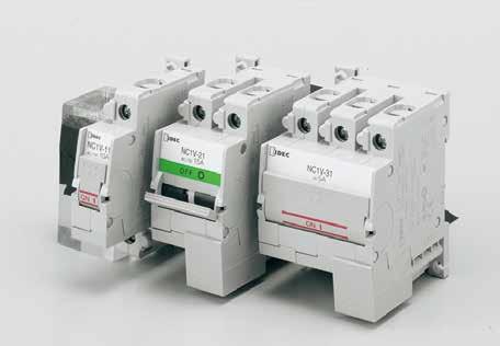
2 ircuit Protector Selection Guide Model NV NHS NHY NHL (w/indicator) NHV Shape ping Method No. of Poles Internal ircuit Rating Retractable Actuator Lever Rocker Rocker Lever Hydraulic-magnetic tripping to 3 poles to 3 poles (Dual-coil:, poles, poles to 3 poles -pole, -pole) Series /urrent Yes Yes Yes Yes Yes Relay /Voltage Yes Yes Yes Yes Yes Dual-coil Yes 50V A, 50/60 Hz Rated Voltage 65 to 5V D (3 types are for A 50V A 50/60 Hz, 65V D only) Rated urrent (urrent ) 0.A to 30A urrent trip: 0.5A to 30A Dual-coil: A to 5A Voltage (Voltage ) 4 to 48V D 00V A, 4V D (Dual-coil: 4V D, 00V A) Rated Interrupting urrent 50V A/500A 65 to 5V D/500A 50V A/65V D 000A (UL/SA rating), 0V A 50/60Hz 000A ( ) Time Delay urves 3 types types for D, 3 types for A auxiliary contactact auxiliary con- Auxiliary ontacts/alarm ontacts Yes Inertia Delay Yes Mounting Style Screw mounting, DIN35mm Rail Panel cut-out (Screw mounting) Panel cut-out (Snap-on mounting) DIN rail mounting, Surface mounting Dimensions (H W D mm, -pole) ertification UL, SA, TUV, E,, UL, c-ul, VDE,, UL, c-ul, VDE, E,, UL, c-ul, VDE, E,, UL, c-ul, VDE, E,, Page Note: See the following pages for further information about the certified products. Model NRLT NRLY NRLY (w/indicator) NRLR NRLR (w/indicator) Shape (LED/Neon) Rocker Hydraulic-magnetic tripping (LED/Neon) Rocker Lever Rocker Rocker ping Method No. of Poles, poles (-lever), poles (-rocker), poles (-rocker), poles (-rocker), poles (-rocker) Internal ircuit Series /urrent Yes Yes Yes Yes Yes Relay /Voltage Yes Yes Yes Yes Yes Switch Type Yes Yes Yes Yes Yes Rated Voltage 50V A 50/60Hz, 50V D Rating Rated urrent (urrent ) 0.5A to 0A urrent trip: For 0.5A to 0A Voltage (Voltage ) 00V A, 4V D Rated Interrupting urrent 50V A/750A (UL rating: 000A), 50V D/500A (UL rating: 000A) Time Delay urves 3 types for D, 3 types for A Auxiliary ontacts/alarm ontacts auxiliary contact auxiliary contact auxiliary contact auxiliary contact auxiliary contact Inertia Delay Mounting Style Panel cut-out (Ring mounting) Panel cut-out (Snap-on mounting) Panel cut-out (Snap-on mounting) Panel cut-out (Screw mounting) Panel cut-out (Screw mounting) Dimensions (H W D mm, -pole) ertification UL, SA, VDE,E, UL, SA, VDE,E, UL, SA, VDE,E, UL, SA, VDE, E, UL, SA, VDE, E, *, *, *, *, *, Page Note: See the following pages for further information about the certified products. * Protectors indicated with are for the relay trip type. Also, the series trip and relay trip types of NRL series are excluded from.
, Surface mounting (Plug-in base), DIN rail mounting (Width: 35 mm) 50.")

 pole to 3 poles Yes Yes Yes Yes Yes 50V A 50/60Hz, 50V D 50V A, 50/60Hz, 65V D urrent trip: For 0.5A to 0A 0.")
3 ircuit Protector Selection Guide NRAS NRAN NRAR NRAR (w/indicator) Lever Lever Rocker Hydraulic-magnetic tripping (LED) (Neon Lamp) Rocker to 3 poles to 3 poles pole pole Yes Yes Yes Yes Yes Yes 50V A 50/60 Hz, 65V D 0.3A to 30A 4V D 50V A/65V D, 000A types for D, 3 types for A Panel cut-out (Screw mounting, snap-on mounting), Surface mounting (Plug-in base), DIN rail mounting (Width: 35 mm) UL, c-ul, VDE, E,, UL, c-ul, VDE, E,, UL, c-ul, VDE, E,, Panel cut-out (Screw mounting), Panel cut-out (Snap-on mounting) UL, c-ul, VDE, E,, NRLK NRLP NRBM Large Rocker Lever Lever Hydraulic-magnetic tripping, poles (-rocker) pole to 3 poles Yes Yes Yes Yes Yes 50V A 50/60Hz, 50V D 50V A, 50/60Hz, 65V D urrent trip: For 0.5A to 0A 0.5A to 0A A to 50A 00V A, 4V D 00V A, 4V D 50V A/750A (UL rating: 000A), 50V D/500A (UL rating: 000A) 50V A/65V D 000A 3 types for D, 3 types for A types for D, 3 types for A auxiliary contact auxiliary contact Panel cut-out (Screw mounting) P board Panel cut-out (Screw mounting) UL, SA, VDE, E, *, UL, SA, VDE,E, UL, c-ul, VDE, E,, Note: UL and SA ratings may differ. See the following pages for details. (ontinued on the next page) 3
 Internal ircuit (urrent ) Series Series trip Maximum ircuit Voltage 3V D, 50V A 3V D, 50V A Rated urrent 300, 500mA,, 3, 5, 8, 0, 5A,.6,, 3.")
4 ircuit Protector Selection Guide Series NRF NRF NRPS NRPF manual OFF mechanism Slim Flat Shape ping method Thermal tripping No. of Poles pole pole (SPST-N, SPDT) Internal ircuit (urrent ) Series Series trip Maximum ircuit Voltage 3V D, 50V A 3V D, 50V A Rated urrent 300, 500mA,, 3, 5, 8, 0, 5A,.6,, 3.5, 4, 5, 6A Rating Rated Interrupting urrent ping Time 300 ma to 5A: Rated current 6 (resistive load) 0, 5A: Rated current 0 (resistive load) No trip at the rated current in hour at 35% the rated current A to 4A: Rated current 0 (resistive load) 5A, 6A: 50V A/40A, 3V D/40A (resistive load) No trip at the rated current in min at 75% the rated current Reset Time min minimum (at 35% the rated current) ( * ) min minimum (at 00% the rated current) ( * ) Time Delay urves type type Auxiliary ontacts Mounting Style Panel cut-out (Snap-on mounting) P board mounting ertification UL, SA, TÜV ( * ), UL, UL, SA Page *: Reset time is the value at the reference ambient temperature of 5. *: TÜV certification: for 8A, 0A and 5A only. ommon Description of ircuit Protectors Internal ircuit Overview and Application Examples Series Series with Auxiliary ontacts Series with Alarm ontacts Dual-coil This is the most common circuit protector, providing excellent overload and short circuit protection. It can also be used as /OFF switch, except NRF and NRP series. Load Relay /Voltage The internal structure is identical to the current tripping protector, but the protective element has no time-delay function and the load circuit is cut off by the instantaneous tripping of the protector. Suitable for purposes, such as cutting off the power supply by using the alarm signal of the secondary circuit of the transformer. Load As the auxiliary contact operation is interlocked with the /OFF of the main contactor, circuit protector operation can be monitored by a lamp. The auxiliary contact can also be used to control auxiliary circuits. Load B Load A The alarm contact is electrically independent of the /OFF of the main contactor, but actuates when the protective element operates. Therefore, the alarm contact can be used with a lamp or buzzer to indicate trip operation and control alarm circuits. After the alarm contact has tripped, turn the lever to set the alarm contact. Load B Load A The dual coil circuit protector is provided with both a series trip (current trip) and relay trip (voltage trip). In the following example circuit, oil A (current coil) performs overload and short circuit protection, while oil B (voltage coil) serves to shut down the circuit when the alarm contact detects an abnormal condition. Power A Applications by Time Delay urve Time Delay urves Applications urve AD The most common curves used for circuit breakers. urve AA urve MD urve MA inertia delay (Inertia delay mechanism) Selection Guide ( ) Dashed lines show the connection when the voltage is the same as that for the load circuit. oil A oil B Power B Load Applying time of tripping voltage: in sec. Suited for motor loads that draw high inrush currents lasting for a rather long period of time. Suited for transformer and lamp loads that draw steep inrush currents. Select an appropriate circuit protector with a required delay curve and rated current in consideration of the characteristics of the circuit or equipment to be protected. When starting an inductive load, the inrush current reaches up to over ten times the rated current. Select the rated current to prevent tripping at starting current. 4 Example Solenoid rating Rated current: 0.7A Inrush current: 3A max. Inrush time: Approx.0. sec Time in sec 0. A (00%) Solenoid load starting current ping Area Type NV urve A 3A (300%) urrent (%) 0A (000%) For solenoid protection such as the above example, NV circuit protector for the rated current A is suited. For semiconductor element, the joint-use of short delay fuse for semiconductor protection is more effective.

5 NV ircuit Protectors IDE s original spring-up, fingersafe terminals enhance reliability and safety. Integrated electric shock protection structure (IP0). Auxiliary/alarm contact terminals and voltage coil terminals on the relay trip types are equipped with terminal covers. Spring-up, fingersafe terminals reduce wiring time. Ring terminals can be installed. aptive terminal screws. Available with inertial delay Available with auxiliary or alarm contacts Rated short-circuit capacity: 500A Slim, space-saving housing -pole: 7.5mm wide -pole: 35.0mm wide 3-pole: 5.5mm wide Retractable actuator The trip-free mechanism maintains the circuit open even when the operator is turned on after tripping. Applicable Standards UL077 SA. No. 35 EN60934 EN GB770 Electrical Applicance and Material Safety Law Technical Standard Specifications Mark Series Relay ertification Organization / File No. UL recognized File No. E6809 SA file No. LR83454 TÜV SÜD European ommission's EU Low Voltage Directive No JET Note: TÜV, E, and marks are applicable for series trip type only. Operator Style Retractable actuator Internal ircuit Series trip (current trip), Relay trip (voltage trip) Protection Method Hydraulic magnetic tripping system, Magnetic tripping system (voltage trip) No. of Poles -pole -pole 3-pole Rated Voltage (A/D) (Note ) 50V A 50/60Hz, 65V D 50V A 50/60Hz, 5V D 50V A, 50/60Hz 50V A, 500A 50V A, 500A Rated Short-circuit apacity 50V A, 500A 65V D, 500A 5V D, 500A Series Rated urrent 0.A, 0.3A, 0.5A, A, A, 3A, 5A, 7A, 0A, 5A, 0A, 5A, 30A (urrent ) Time delay curve curve M (slow), curve A (medium), S (instantaneous) haracteristics (Note ) urves M and A are avilable with inertial delay. Relay Rated urrent 30A (Voltage ) 4 to 48V D (at 5 ) (Note 3) Voltage Voltage application duration 0 sec maximum, tripping time 0. sec maximum (at rated voltage) Auxiliary ontact/ ontact Rating 5V A 3A (resistive load), 30V D A (resistive load) Alarm ontact Minimum Applicable Load 4V D ma (resistive load, reference value) Insulation Resistance 00 MΩ minimum (500V D megger) Dielectric Strength 000V A, minute (between terminals when main contacts are open, between live parts of different poles, between live and dead parts) 600V A (between terminals when auxiliary circuits are open) Vibration Resistance Damage limits: 47 m/s (0 to 55 Hz) (-pole, -pole), 78 m/s (3-pole) (with rated current applied) Operating extremes: 98 m/s (-pole, -pole), 78 m/s (3-pole) Shock Resistance Damage limits: 490 m/s (S time delay curve: 80% rated current, (-pole, -pole), 97 m/s (3-pole) Operating extremes: 96 m/s A, M time delay curve: 00% rated current) Electrical Life 0,000 cyles minimum (at rated curent), 0 operations per minute Reference Temperature 40 0 to +60 (no freezing) Operating Tempperature Rated current is based on an ambient temperature of 40. When the operating temperature exceeds 40, derate the rated current by using the factors shown below. Storage Temperature 40 to +60 (no freezing) Operating Humidity 45 to 85% RH (no condensation) Storage Humidity 45 to 85% RH (no condensation) Style Main ircuit Spring-up, fingersafe terminal: M4 screw (up to 0A), M5 screw (5A and 30A) Auxiliary/Alarm ontacts, Voltage oil M3.5 screw Weight (approx.) -pole: 90g, -pole: 70g, 3-pole: 60g Note : 3-pole type is for A voltage only. Note : For S (instantaneous) tripping curve, humming sound may be caused when used in an A sinusoidal-wave current circuit around 80% of the rated current, however, the performance of the circuit protector will not be affected. To avoid unnecessary tripping, do not use in circuits where inrush currents may be present. Note 3: Relay trip (voltage trip) type is not equipped with an overcurrent trip function. Do not use the NV circuit protectors in environments where they are exposed to extreme temperature, humidity, dust, corrosive gases, vibration, shock, or in a circuit where inrush current may be present, otherwise unnecessary operations and damage may occur. Operating Temp. Derating Factor
6 NV ircuit Protectors Part No. Development Auxiliary/Alarm ontacts 00: None : one auxiliary contact : two auxiliary contacts 3: three auxiliary contacts : one alarm contact 3: one auxiliary contact and one alarm contact 3: two auxiliary contacts and one alarm contact Specity rated current, time delay curve, or voltage trip coil voltage in place of in the Part No. Internal ircuit 3 4 No. of Poles Inertial Delay NV - 00 F - 30A A D4V Model 8 NV: Flap actuator type DIN rail and panel mounting No. of Poles 7 : -pole : -pole 3: 3-pole Internal ircuit : Series trip (current trip) 5: Relay trip (voltage trip) 6 Auxiliary ontact Alarm ontact Part No. 5 Voltage oil Voltage D4V: 4-48V D * Specified for relay trip only. Time Delay urve M: Slow A: Medium S: Instantaneous * For both A/D. * Specified for series trip only. Rated urrent 0.A, 0.3A, 0.5A, A, A, 3A, 5A, 7A, 0A 5A, 0A, 5A, 30A * Specified for series trip only. Inertial Delay Blank: F: * Inertial delay is for A voltage only. * Available with medium and slow types (not applicable with relay trip). ode 6 Rated urrent 7 Time Delay urve 8 Voltage oil Voltage Series (urrent ) Relay (Voltage ) -pole -pole 3-pole -pole NV One Auxiliary ontact NV One Alarm ontact NV NV-00F- 6 7 One Auxiliary ontact NV-F- 6 7 One Alarm ontact NV-F- 6 7 NV One Auxiliary ontact NV Two Auxiliary ontacts NV One Alarm ontact NV One Auxiliary ontact and One Alarm ontact NV NV-00F- 6 7 One Auxiliary ontact NV-F- 6 7 Two Auxiliary ontacts NV-F- 6 7 One Alarm ontact NV-F- 6 7 One Auxiliary ontact and One Alarm ontact NV-3F- 6 7 NV One Auxiliary ontact NV Two Auxiliary ontacts NV Three Auxiliary ontacts NV One Alarm ontact NV One Auxiliary ontact and One Alarm ontact Two Auxiliary ontacts and One Alarm ontact NV NV NV-300F- 6 7 One Auxiliary ontact NV-3F- 6 7 Two Auxiliary ontacts NV-3F- 6 7 Three Auxiliary ontacts NV-33F- 6 7 One Alarm ontact NV-3F- 6 7 One Auxiliary ontact and One Alarm ontact Two Auxiliary ontacts and One Alarm ontact NV-33F- 6 7 NV-33F- 6 7 NV pole NV pole NV A 0.3A 0.5A A A 3A 5A 7A 0A 5A 0A 5A 30A M (slow) A (medium) S (instantaneous) 4V D Note: Inertial delay is for A circuit. Also, time delay curve of S (instantaneous) is not available with inertial delay. 6
7 NV ircuit Protectors Internal ircuit -pole NV-00 ( auxiliary/alarm contacts) NV- ( auxiliary contact) NV- ( alarm contact) NV-500 (Relay ) One auxiliary contact. One alarm contact. A B N O N N O N D -pole NV-00 ( auxiliary/alarm contacts) NV- ( auxiliary contact) NV- ( alarm contact) NV-500 (Relay ) One auxiliary contact. Also available with two auxiliary contacts. One alarm contact. Also available with one auxiliary contact and one alarm contact. A A B B N O N N O N D D Note: Those with two auxiliary contacts and with one auxiliary contact and one alarm contact have been applied for UL and. 3-pole NV-300 ( auxiliary/alarm contacts) NV-3 ( auxiliary contact) NV-3 ( alarm contact) NV-3500 (Relay ) One auxiliary contact. Also available with two or three auxiliary contacts. One alarm contact. Also available with one auxiliary and one alarm contacts, and two auxiliary and one alarm contacts. A A A B B B N O N N O N D D D Note: Those with two or three auxiliary contacts, with one auxiliary contact and one alarm contact, and with two auxiliary contacts and one alarm contacts have been applied for UL and. Overcurrent-Time Delay haracteristics (sec at 40 ) [vertical mounting] Item Time Delay urve S (instantaneous) NO TRIP Percent of Rated urrent 00% 5% 50% 75% 00% 400% 600% 800% 000% *0.005 to to to to to to to 0.0 A (50/60 Hz)/D A (medium) NO TRIP *5 to 40 6 to 40 6 to to to to to 0.65 M (slow) NO TRIP *60 to to 00 9 to to to to to 0.8 A (50/60 Hz) Inertial Delay A (medium) Inertial Delay M (slow) NO TRIP 5 to 40 6 to to 6 NO TRIP 60 to to to to to to to to to.75 *: MAY TRIP on D 7
8 NV ircuit Protectors Time Delay urves at D (Note) A urve A (medium) D (Note) A urve M (slow) Time in sec 0 Time in sec urrent (percent load of the rated current) urrent (percent load of the rated current) D (Note) urve S (instantaneous) Note: The entire shaded area applies to A. For D, the shaded area on the right of the dashed line applies. 0 Time in sec 0. A urrent (percent load of the rated current) urve A (medium) Inertia Delay urve M (slow) Inertia Delay 0 0 Time in sec 0. Time in sec urrent (percent load of the rated current) urrent (percent load of the rated current) 8
9 NV ircuit Protectors Time Delay urve and Ambient Temperature NV circuit protectors employ an electromagnetic tripping system, where the rated current (trip current) is not affected by ambient temperatures. But the time delay may vary with the oil viscosity in the oil dash pot. Lower oil viscosity at higher temperatures results in a shorter delay, whereas at lower temperatures the delay will be longer. Temperature orrection urve The time delay curves on the preceding page are measured at 40. reference to the following curves, time delays can be corrected according to ambient temperature. Inertial Delay Inertial delay is designed not to trip on a non-repeating single pulse of 0 times the rated current (peak value) for a duration of 8 ms. In addition, circuit protectors equipped with inertial delay do not respond to high inrush currents caused by transformer or lamp loads, but perform the specified interruption on the subsequent overcurrents. Inertial delay is available on A circuits, and is not available with the series trip curve S (instantaneous) Percent of rated current Pulse peak current 00 Protector rated current. Sinusoidal or parabolic pulse hange of Time Delay (%) Percent of Rated urrent (%) Pulse width (Duration) Pulse peak current Ambient Temperature ( ) The time delay is based on an ambient temperature of 40. Time delays at other temperatures are corrected according to the temperature correction curve. The time delay of the instantaneous time delay curve (S) is not affected by the ambient temperature Pulse Width (ms) When operating temperature exceeds 40, derate the rated current by multiplying the derating factor shown on the right. Operating Temp. Derating Factor Impedance and oil Resistance Series (urrent ) (initial value) at 5 Rated urrent For A 50/60 Hz Impedance (Ω) For D Resistance (Ω) urve S urves A, M urve S urves A, M 0.A A A A A A A A A A A A A Tolerance: ±5% (up to 0A), ±50% (5A and 30A) Voltage Drop Due to oil Resistance or Impedance The internal resistance or impedance of a circuit protector tends to be larger for a smaller rated current. Therefore, when circuit protectors of a small rated current are used, voltage drop should be taken into consideration. Internal resistance also varies with time delay curves, which should also be considered during installation. Main ontact - Auxiliary/Alarm ontact [Auxiliary ontact] Main ontact NO ontact N ontact closed open ped open closed OFF open closed [Alarm ontact] Main ontact NO ontact N ontact open closed ped closed open OFF open closed Relay (Voltage ) at 5 ping Voltage For D Resistance (Ω) 4-48V 00.0 Tolerance: ±5% 9
10 NV ircuit Protectors Dimensions -pole All dimensions in mm..0 M4 Screw (up to 0A) M5 Screw (5A, 30A) DIN Rail (BAA, BAP, BADA) NV ø4.5 Holes (for screw mounting) DIN Rail (BAA, BAP, BADA) NV- (Auxiliary ontact) NV- (Alarm ontact) M4 Screw (up to 0A) M5 Screw (5A, 30A) N NO Mounting Hole Layout (M4 Mounting Screws) 7.4 M3.5 Screw 7.5 -ø4.5 Holes (for screw mounting) M M5 Screw (30A) DIN Rail (BAA, BAP, BADA) NV-500 (Relay ) oil M3.5 Screw -ø4.5 Holes (for screw mounting) pole DIN Rail (BAA, BAP, BADA) 9.5 M4 Screw (up to 0A) M5 Screw (5A, 30A) Mounting Hole Layout (M4 Mounting Screws) NV M ø4.5 Holes (for screw mounting)
11 NV ircuit Protectors -pole NV- (one auxiliary contact) NV- (two auxiliary contacts) NV- (one alarm contact) NV-3 (one auxiliary contact and one alarm contact) M4 Screw (up to 0A) M5 Screw (5A, 30A) N NO M3.5 Screw -ø4.5 Holes (for screw mounting) The dimensions are for NV- and NV DIN Rail (BAA, BAP, BADA) Mounting Hole Layout (M4 Mounting Screws) M5 Screws (30A) 6.6 DIN Rail (BAA,BAP,BADA) M4 7.4 NV-500 (Relay ) oil M3.5 Screw -ø4.5 Holes (for screw mounting) pole 47.0 M4 Screw (up to 0A) M5 Screw (5A, 30A) DIN Rail (BAA, BAP, BADA) NV Mounting Hole Layout (M4 Mounting Screws) 5.5 -ø4.5 Holes (for screw mounting) NV-3 (one auxiliary contact) NV-3 (two auxiliary contacts) NV-33 (three auxiliary contacts) NV-3 (one alarm ontact) NV-33 (one auxiliary contact and one alarm contact) NV-33 (two auxiliary contacts and one alarm contact) M4 Screw (up to 0A) M5 Screw (5A, 30A) N NO M3.5 Screw -ø4.5 Holes (for screw mounting) The dimensions are for NV-3 and NV-3. DIN Rail (BAA, BAP, BADA) M4 7.4
 5.0 5.3 33.0 Accessories All dimensions in mm.")
, steel (screw, washer) N9Z-MA N9Z-MA 3-pole N9Z-MA3 N9Z-MA3 Package Quantity Remarks Used for mounting NV")

12 NV ircuit Protectors (Accessories) 3-pole All dimensions in mm M5 Screw (30A) DIN Rail (BAA, BAP, BADA) Mounting Hole Layout (M4 Mounting Screws) 47.0 NV-3500 (Relay ) oil M3.5 Screw -M ø4.5 Holes (for screw mounting) Accessories All dimensions in mm. Panel Mounting Bracket (Note) -pole -pole 3-pole Wiring clip Shape Material Part No. Ordering No. Bracket Wiring clip -pole N9Z-MA N9Z-MA -pole Bracket: Steel Wiring clip: brass (terminal), steel (screw, washer) N9Z-MA N9Z-MA 3-pole N9Z-MA3 N9Z-MA3 Package Quantity Remarks Used for mounting NV circuit protectors in a panel cut-out. Supplied with two wiring clips for each pole, used for wiring from the rear. For -pole: wiring clips For -pole: 4 wiring clips For 3-pole: 6 wiring clips Marking Plate Installation Example Label attached to the marking plate Marking Plate PBT N9Z- PW N9Z-PWPN0 0 Available for -pole circuit only. For use on -pole circuit protectors, break the marking plate into two halves. Label is supplied by the user. Padlock Attachment Polyamide body with stainless steel pin N9Z-LK N9Z-LK Locks the retractable actuator in the off position to prevent NV from being switched on inadvertently. an be used on -, -, and 3-pole. DIN Rail (35mm-wide) Aluminum BAA000 BAA000PN0 Weight: approx. 00g Length: 000mm Steel BAP000 BAP000PN0 0 Weight: approx. 30g BAA BAP BADA Aluminum BADA000 BADA000PN0 Weight: approx. 80g End lip (4) 45 9 Steel (trivalent chromate) BNL6 BNL6PN0 0 Applicable rail: BAA, BAP, BADA Weight: approx. 5g Note: annot be used with NV with auxiliary or alarm contact.
13 NV ircuit Protectors (Accessories) Dimensions N9Z-MA Panel Mounting Bracket 57.4 (59) () 63.7 () (94.3) (7) A M3 Dimensions A and B Dimension A B -pole pole pole Mounting Hole Layout -ø Panel Mounting Screw Length (Dimension in mm) B Applicable Panel Thickness: 0.8 to 3. mm The outside diameter of the M3 screw (including washer) must be 7 mm maximum. Panel thickness (mm) washer plain washer (0.5 thick) spring washer (0.7 thick) plain washer (0.5 thick) and spring washer (0.7 thick) ountersunk head screw Tightening torque: 0.5 to 0.8 N m The screw length behind the panel must be 9 mm maximum. N9Z-TA Wiring lip M5 0.8 ø N9Z-PW Marking Plate Marking Plate Installed on the ircuit Protector When installed on a 34.5 (49.8) -pole circuit protector Insulation Sleeve When using wiring clips on - or 3-pole circuit protectors, install UL/SA-rated insulation sleeves on the crimping terminals to ensure the air gap required by UL077. Applicable Insulation Sleeves (Example) Nissei Eco (V-38) Tokyo Dip (TP-038) Nichifu (TI38) Applicable rimping 9. max. M5 Tightening torque:.8 to. N m Materials Panel Mounting Bracket: Steel Wiring lip: Brass (terminal strip) Steel (screw, washer) Break line ø6.5 (48.4) When used on a -pole circuit protector, break the marking plate along this line. Material: PBT (35) N9Z-LK Padlock Attachment Rail mm-wide DIN rail and IDE channel base Pin 6.5 Body Pin Padlock Attachment Installed BAA: BAP: BAA BAP BADA

14 NV ircuit Protectors Instructions Replacement Parts over Shape Material Part No. Ordering No. Package Quantity All dimensions in mm. Remarks PA66 NV-AUX-V NV-AUX-V Wiring lip : Brass Screw/washer: Steel N9Z-TA N9Z-TAPN0 0 Instructions Installation Angle ping method is hydraulic magnetic. Minimum operating current varies with installation angle. Operating currents are influenced by the weight of movable iron core. reference to the following figures, correct the rated current. 00% Applicable Wire and rimp Main ircuit s Screw Spring-up, fingersafe, slotted Phillips screw with square washer (up to 0A) Spring-up fingersafe terminal (5A and 30A) onnectable Wire Size (mm ) Applicable rimping 0.5 to.65 R to.63 R-4.63 to 6.64 R to.65 R to.63 R-5.63 to 6.64 R5.5-5 Tightening Torque (N m) to.4.8 to. Auxiliary ontact Alarm ontact Voltage oil s Slotted Phillips screw with square washer 0.5 to.65 R to.63 R to 0.9 Minimum operating current is calculated from the following formula: (Minimum operating current) = (Rated current) (orrection factor by installation angle) (Reference minimum tripping current rate) DIN Rails [Installation on DIN Rail]. Fasten the DIN rail securely.. the latch facing downward, install the NV circuit protector on the DIN rail as shown below. [Removal from DIN Rail] Using a flat screwdriver, pull the latch on the circuit protector to remove from the DIN rail. Installing 0% 90% 00% 35mm-wide DIN Rail Removing 35mm-wide DIN Rail For wiring the main circuit terminal, use the applicable crimp terminals and tighten to the recommended tightening torque. When using the NV circuit protector as SA-certified product, use with SA-certified crimp terminal. When using the NV circuit protector as UL-listed product, use with UL-listed crimp terminal. Panel Mounting Screw (not supplied) Screw Size Tightening Torque Shape Spring Washer M4 0.8 to.0 N m Plain Washer Product Markings (Example: NV--30AA) Part No. Rated Voltage Rated urrent P E S 0VA J E T 30A IRUIT PROTETOR PSE ertification No. of Poles Time Delay urve Auxiliary/Alarm ontact Rating Reference Operating Temperature ertification Marks Installation of Auxiliary/Alarm over After wiring the terminals, install the terminal cover by aligning the terminal cover with the circuit protector as shown below. I..500A NV- POLE Ue 50VA 50/60Hz 65VD In 30A URVE A Suppl. Prot. AUX. SW 5VA 3A 30 VD A A.T. 40 JAPAN Push Flat Srcrewdriver Latch cover installed 4

: to.4 N m")
 Note: NV circuit protectors with auxiliary/alarm contacts cannot be used with mounting brackets. ➁ Turn the body. Padlock ➂ Install the body on the retractable actuator as shown below.")
 (B) D E (F) G 9 to 5 35 to 4 9 to.5 4 to 4.5 to 5 8 to 0 7.5 to 9.")
15 NV ircuit Protectors Instructions Instructions Installing Auxiliary/Alarm over onnect the terminal before installing the terminal cover. Installing Attach the latch on TOP side and install the terminal cover as shown below. Hole Body Retractable Actuator Single Pole Pin Push the pin in the direction of arrows, and insert the pin in the holes. Installing N9Z-MA Panel Mounting Brackets. Insert the wiring clip into the terminal of the circuit protector, and tighten. Tightening torque to the main circuit terminal 0A max. (M4): to.4 N m 5A, 30A (M5):.8 to. N m. Insert the panel mounting bracket to the circuit protector. 3. Install the rear of the panel mounting bracket into the DIN rail recess on the circuit protector and push in the clamp. (Example) Note: NV circuit protectors with auxiliary/alarm contacts cannot be used with mounting brackets. ➁ Turn the body. Padlock ➂ Install the body on the retractable actuator as shown below. ➃ Slide the pin to the lock position. The padlock is not supplied with the padlock attachment and must be supplied by the user. The total weight of the padlock can be a maximum of 45g. Make sure the padlock weight does not exceed 45g, otherwise the NV circuit protector may be damaged. Applicable Padlock Size (A) (B) D E (F) G 9 to 5 35 to 4 9 to.5 4 to 4.5 to 5 8 to to 9.0 Note: (A) (B) (F) are for reference only. Installing the N9Z-PW Marking Plate E D Available for -pole circuit protectors only. For use on -pole circuit protectors, break the marking plate into two halves. Marking Range (B) G NV Align with the marking plate with the holes and press it to the terminals. 4.0 (Example) Solenoid Valveircuit (A) Recommended Padlock Manufacturer Part No. Alpha Master Lock 40 (F) Installing the N9Z-LK Padlock Attachment ➀ Pull down the retractable actuator, and install the padlock attachment on the circuit protector. -pole: Insert the pin into the holes under the retractable actuator. - or 3-pole: Insert the pin into the holes in the center of the circuit protector. Safety Precautions When using the padlock, do not use the NV circuit protector where it is subject to vibration or shock, otherwise failure or damage may result. Do not apply a force of more than 50N on the retractable actuator, otherwise the actuator will be damaged. When using three or more -pole NV circuit protectors adjacently, facilitate installing the padlock attachment by providing a clearance of 6mm minimum between the protectors, or by using the tweezers or flat screwdriver. 5
 Available with dual-coil Available with auxiliary contact or alarm contacts.")


 Relay trip (Voltage trip) Series trip with auxiliary contacts Series trip with alarm")
16 6 NH Series ircuit Protectors Wide Range of Applications from Office Automation and onsumer Use to Factory Automation. ompact, lightweight, and high-performance circuit protectors. Rocker type snaps into a panel. Rated voltage: 50V A and 65V D 35mm-wide DIN rail mounting (NHV) Available with dual-coil Available with auxiliary contact or alarm contacts. Available with inertia delay Hydraulic-magnetic tripping system Safe trip-free mechanism Available in tab terminal and screw-terminal. This product is recognized by Underwriters Laboratories under UL077 as a "Supplementary Protector." Applicable Standards UL077 SA. No. 35 (Note ) EN60934 (VDE064) (Note ) EN6093 (Note ) Mark ertification Organization / File No. UL/c-UL recognized File No. E6809 No EU Low Voltage Directive GB770 No Electrical Appliance and Material Safety Law JET Technical Standard For details, see the list of standard certified products in the back of this catalog. Note : Series trip, relay trip, dual coil (for A) Note : Series trip Specifications Model NHS NHY NHL NHV Dual-coil NHS Operator Style Lever Rocker Rocker (w/indicator) Lever Lever Protection Method Hydraulic-magnetic tripping system Hydraulic-magnetic tripping system Internal ircuit Series trip (urrent trip) Relay trip (Voltage trip) Series trip with auxiliary contacts Series trip with alarm contacts (NHS and NHV only) Series trip (urrent trip) + Relay trip (Voltage trip) No. of Poles,, 3 poles, poles, poles,, 3 poles, poles Rated Voltage 50V A 50/60Hz, 65V D 50V A 50/60Hz, 65V D Minimum Applicable Load 4V A/D, 00mA (reference value) Rated urrent urrent trip: 0.5A, 0.75A, A, A, 3A, 5A, 7.5A, 0A, 5A, 0A, 5A, 30A urrent trip: A, 3A, 5A, 7.5A, 0A, 5A coil voltage: Voltage 00V A 50/60Hz, 4V D (operating at 90% of the rated voltage or higher, at 5 ) 4V D, 00V A (operating at 90% Voltage application duration: sec maximum of the rated voltage or higher, at 5 ) time: 0.05 sec maximum (at the rated voltage) Voltage application duration: sec - max. time: 0.05 sec max. (at the rated voltage) Rated Interrupting 50V A 50/60Hz 000A, 65V D 000A (UL/-UL ratings) urrent 0V A 50/60Hz 000A ( ) Auxiliary ontact Alarm ontact SPDT microswitch 50V A, 3A (resistive load) Reference Temperature +5 Operating Temperature -40 to +85 (no freezing) Storage Temperature -40 to +85 (no freezing) Operating Humidity 45 to 85% RH (no condensation) Storage Humidity 45 to 85% RH (no condensation) Insulation Resistance 00 MΩ minimum (500V D megger) Dielectric Strength Between operator and live part, between terminals when main contacts are open, between live parts of different poles, and between main terminal and auxiliary contact terminal: 3750V A, min (NHV: 500V A, min) Between terminals when auxiliary contacts are open: 600V A, min Between operator and live part, between terminals when main contacts are open, between live parts of different poles, between voltage trip terminal and main terminal: 500V A, min. Vibration Resistance Damage limits: 0 too 55 Hz, 00 m/s (,, 3 pole) Operating extremes: 0 to 55 Hz, 98 m/s (,, 3 pole) (with the rated current applied) Shock Resistance Damage limits: 000 m/s, Operating extremes: 500 m/s with the rated current applied. (Auxiliary/alarm contact: 300 m/s ) Life 0,000 cycles min. (Electrically 6,000 cycles: 6 operations per minute at the rated current, mechanically 4,000 cycles: 6 operations per minute) Style Main terminal: Tab terminal #50, M4 screw terminal Auxiliary terminal: Tab terminal #0 Main terminal: M4 screw terminal (0A max.) M5 screw terminal (5, 30A) Auxiliary terminal: M3.5 screw terminal Mounting Style Screw mounting Snap mounting Screw mounting, DIN rail mounting Screw mounting Weight (Approx.) -pole: 45g -pole: 90g 3-pole: 35g -pole: 50g -pole: 00g Rocker NHY (-pole) Lever NHS -pole: 65g -pole: 30g 3-pole: 95g (-pole) Rocker NHL (w/indicator) Lever NHV (Direct DIN rail mounting ) Main terminal: Tab terminal #50 Auxiliary terminal: Tab terminal #87 -pole: 45g -pole: 90g Do not use the NH series circuit protectors in environments where they are exposed to extreme temperature, humidity, dust, corrosive gases, vibration, shock, or in a circuit where inrush current may be present, otherwise unnecessary operations and damage may occur.
17 NH Series ircuit Protectors Rocker olor, Rocker Indication (NHY/NHL) Rocker olor Rocker (ode) Indication (ode) Black (blank) Red (R), Green (G), White (W) OFF (blank) (A) () (D) Note: Rocker indication is white (black when rocker color is white). Part No. Example Model No. of Poles Internal ircuit Auxiliary ontact, Alarm ontact (Dual-coil: blank) Inertia Delay (with / without) Operating Voltage of Indicator (NHL) Indicator Rated Voltage ode Neon (Red) LED (Red) [Note] NHL - 00 F- 3 AAAR 5V A, 50/60Hz (operating voltage: 00 to 5V A) For A/D (operating voltage: within +0% of the rated voltage) 6V 3 V 4 4V 5 48V 6 Note: Both indicators contain a current limiting resistor. Lever olor (NHS, NHV): Black Only NHY and NHL Rocker olor Rocker Indication Ratings of Indicator Time Delay urves Rated urrent Operation of Auxiliary ontacts Since auxiliary contact operations are interlocked with /OFF positions of main terminal, operating status of the circuit protector can be monitored using a lamp. Auxiliary contacts also serve as a control of auxiliary circuits. Operator Position NO ontact N ontact losed Open ped Open losed OFF Open losed Operation of Alarm ontacts Alarm contacts are not interlocked with main contacts and operate only when an overcurrent occurs. Operator Position NO ontact N ontact Open losed ped losed Open OFF Open losed Part No. Development Operator Style 5 Inertia Delay 6 Style 9 Voltage oil Voltage 0 Indicator Rated Voltage Rocker Indication Lever (ode) Tab (ode) Rated NHS Blank NHL with Indicator only NHY and NHL Blank Voltage (ode) rocker style only Rocker (w/o indicator) NHY Rocker (w/indicator) NHL Lever NHV (Direct and DIN rail mounting) F Not possible to designate with voltage trip type. Screw S Screw terminal is available with Series only. Designation is not required for NHV. Dual-coil 00V A 00 4V D 4 Relay 00V A 00V A 4V D 4V D Light Source Neon LED Indicator Rated Voltage 5V A 50/60Hz 6V A/D V A/D 4V A/D 48V A/D (ode) OFF (blank) (A) () (D) NHS 00 F S 3 AA No. of Poles 3 Internal ircuit 4 Auxiliary ontact 7 Rated urrent 8 Time Delay urve Rocker olor -pole (ode) Series (ode) (ode) Rated NHY and NHL rocker A D (urrent ) 00 urrent ode style only -pole Relay w/auxiliary ontact 0.5A 0.5 MA MD olor (ode) 3-pole 3 5 (Voltage ) w/alarm ontact 0.75A 0.75 AA AD Black Blank 3-pole is available Dual-coil: Blank A BA Red R Dual oil with NHS Series 6 "w/alarm ontact" is *A To be designated for Green G (Series trip plus, NHS Relay available with NHS and *3A current trip and dual coil. White W relay trip) 3, and NHV. NHV. *5A 5 Note: Dual coil is Dual coil is available with NHS *7.5A 7.5 available with Tab only. *0A 0 -pole and *5A 5 -pole only. 0A 0 5A 5 30A 30 Dual-coil: *only 7
18 NH Series ircuit Protectors NHS (Lever ) Specify a rated current, time delay curve, and rated voltage in place of Package Quantity: Internal ircuit Series urrent Series urrent Series urrent No. of Poles 3 Style Tab Screw Tab Screw Tab Screw Inertia Delay Auxiliary ontact Alarm ontact Part No. NHS w/auxiliary ontact NHS w/alarm ontact NHS NHS-00F- 7 8 w/auxiliary ontact NHS-F- 7 8 w/alarm ontact NHS-F- 7 8 NHS-00S- 7 8 w/auxiliary ontact NHS-S- 7 8 w/alarm ontact NHS-S- 7 8 NHS-00FS- 7 8 w/auxiliary ontact NHS-FS- 7 8 w/alarm ontact NHS-FS- 7 8 NHS w/auxiliary ontact NHS w/alarm ontact NHS NHS-00F- 7 8 w/auxiliary ontact NHS-F- 7 8 w/alarm ontact NHS-F- 7 8 NHS-00S- 7 8 w/auxiliary ontact NHS-S- 7 8 w/alarm ontact NHS-S- 7 8 NHS-00FS- 7 8 w/auxiliary ontact NHS-FS- 7 8 w/alarm ontact NHS-FS- 7 8 NHS w/auxiliary ontact NHS w/alarm ontact NHS NHS-300F- 7 8 w/auxiliary ontact NHS-3F- 7 8 w/alarm ontact NHS-3F- 7 8 NHS-300S- 7 8 w/auxiliary ontact NHS-3S- 7 8 w/alarm ontact NHS-3S- 7 8 NHS-300FS- 7 8 w/auxiliary ontact NHS-3FS- 7 8 w/alarm ontact NHS-3FS Rated urrent 0.5A 0.75A A A 3A 5A 7.5A 0A 5A 0A 5A 30A Designation ode 8 Time Delay urve AA BA MA AD MD 9 Rated Voltage NHS Relay Voltage Tab NHS V A 4V D 3 NHS Dual-coil Tab Tab NHS NHS-6F NHS NHS-6F A 3A 5A 7.5A 0A 5A AA BA MA AD MD 00V A 4V D 8
19 NH Series ircuit Protectors NHY (Rocker) Specify a rated current, time delay curve, rated voltage, rocker indication, and rocker color in place of Package Quantity: Internal ircuit Series urrent Series urrent No. of Poles Style Tab Screw Tab Screw Inertia Delay Auxiliary ontact Alarm ontact Part No. NHY w/auxiliary ontact NHY w/alarm ontact NHY-00F- 7 8 w/auxiliary ontact NHY-F- 7 8 w/alarm ontact NHY-00S- 7 8 w/auxiliary ontact NHY-S- 7 8 w/alarm ontact NHY-00FS- 7 8 w/auxiliary ontact NHY-FS- 7 8 w/alarm ontact NHY w/auxiliary ontact NHY w/alarm ontact NHY-00F- 7 8 w/auxiliary ontact NHY-F- 7 8 w/alarm ontact NHY-00S- 7 8 w/auxiliary ontact NHY-S- 7 8 w/alarm ontact NHY-00FS- 7 8 w/auxiliary ontact NHY-FS- 7 8 w/alarm ontact 7 Rated urrent 0.5A 0.75A A A 3A 5A 7.5A 0A 5A 0A 5A 30A 8 Time Delay urve AA BA MA AD MD Designation ode 9 Rated Voltage Rocker Indication Blank, A,, D Rocker olor Blank, R, G, W NHY Relay Voltage Tab NHY V A 4V D Blank, A,, D Blank, R, G, W 9
20 NH Series ircuit Protectors NHL (Rocker w/indicator) Specify a rated current, time delay curve, rated voltage, indicator, rocker indicator, and rocker color in place of Package Quantity: Internal ircuit Series urrent Series urrent No. of Poles Style Tab Screw Tab Screw Inertia Delay Auxiliary ontact Alarm ontact Part No. NHL w/auxiliary ontact NHL w/alarm ontact NHL-00F w/auxiliary ontact NHL-F w/alarm ontact NHL-00S w/auxiliary ontact NHL-S w/alarm ontact NHL-00FS w/auxiliary ontact NHL-FS w/alarm ontact NHL w/auxiliary ontact NHL w/alarm ontact NHL-00F w/auxiliary ontact NHL-F w/alarm ontact NHL-00S w/auxiliary ontact NHL-S w/alarm ontact NHL-00FS w/auxiliary ontact NHL-FS w/alarm ontact 7 Rated urrent 0.5A 0.75A A A 3A 5A 7.5A 0A 5A 0A 5A 30A 8 Time Delay urve AA BA MA AD MD Designation ode 9 Rated Voltage 0 Indicator : Neon 5V A 50/60Hz 3: LED 6V A/D 4: LED V A/D 5: LED 4V A/D 7: LED 48V A/D Rocker Indication Blank, A,, D Rocker olor Blank, R, G, W Relay Voltage NHL Tab NHL V A 4V D : Neon 5V A 50/60Hz 3: LED 6V A/D 4: LED V A/D 5: LED 4V A/D 7: LED 48V A/D Blank, A,, D Blank, R, G, W 0
21 NH Series ircuit Protectors NHV (Lever) Specify a rated current, time delay curve, and rated voltage in place of Package Quantity: Internal ircuit No. of Poles Inertia Delay Auxiliary ontact Alarm ontact Part No. 7 Rated urrent ode for Ordering 8 Time Delay urve 9 Rated Voltage NHV Series urrent 3 w/auxiliary ontact NHV w/alarm ontact NHV NHV-00F- 7 8 w/auxiliary ontact NHV-F- 7 8 w/alarm ontact NHV-F- 7 8 NHV w/auxiliary ontact NHV w/alarm ontact NHV NHV-00F- 7 8 w/auxiliary ontact NHV-F- 7 8 w/alarm ontact NHV-F- 7 8 NHV w/auxiliary ontact NHV w/alarm ontact NHV NHV-300F- 7 8 w/auxiliary ontact NHV-3F- 7 8 w/alarm ontact NHV-3F A 0.75A A A 3A 5A 7.5A 0A 5A 0A 5A 30A AA BA MA AD MD NHV Relay Voltage NHV V A 4V D 3 NHV
 A A N NO B B NHS NO N D D D NHY NO N B A NHL w/indicator (Lead Wire A) (Lead Wire B) (Lead Wire A) (Lead Wire B) NO N D B (Lead Wire A) (Lead Wire B) A Shape (Rear View)")

22 NRBM Series Load NH Series ircuit Protectors Internal ircuits and Arrangements Model Internal ircuit Series (urrent ) Series (w/auxiliary contact) Series (w/alarm contact) Relay (Voltage ) Dual oil Series + Relay (Voltage ) A A N NO B B NHS NO N D D D NHY NO N B A NHL w/indicator (Lead Wire A) (Lead Wire B) (Lead Wire A) (Lead Wire B) NO N D B (Lead Wire A) (Lead Wire B) A Shape (Rear View) (Photo: NHS) Note: The -pole with auxiliary or alarm contact has the contacts on the left side as viewed from the front. The 3-pole with auxiliary and alarm contacts has the contacts on the center. See the dimensional drawings for the terminal arrangement. Wiring Example Lead Wires for Neon and LED Indicators: NH Series Lead Wire olor Neon LED Lead wire A Red A Positive Load Lead wire B Black A Negative NHV Model Internal ircuit Series (urrent ) Series (w/auxiliary contact) Series (w/alarm contact) Relay (Voltage ) N NO NO N A B NHV D Shape Note: See the dimensional drawings for the terminal arrangement.
23 NH Series ircuit Protectors Overcurrent - Time Delay haracteristics (sec at 5 ) [at vertical mounting] For A 50/60Hz D Time Delay Percent of Rated urrent urve 00% 5% 50% 00% 400% 600% 800% 000% AA No BA No MA No AD No MD No Note: ircuit protectors with inertia delay may have a slightly longer time delay at 400% or higher. Dual oil For A 50/60Hz D Time Delay Percent of Rated urrent urve 00% 5% 50% 00% 400% 600% 800% 000% AA No trip BA No trip MA No trip AD No trip MD No trip Note: ircuit protectors with inertia delay may have a slightly longer time delay at 400% or higher. Time Delay urves Note: The dashed lines show dual coil. For A urve AA (at 5 ) 00 urve BA (at 5 ) 00 urve MA (at 5 ) Time in sec 0 0. Time in sec 0 0. Time in sec urrent (percent load of the rated current) urrent (percent load of the rated current) urrent (percent load of the rated current) For D urve AD (at 5 ) urve MD (at 5 ) Time in sec 0 0. Time in sec urrent (percent load of the rated current) urrent (percent load of the rated current) 3
24 NH Series ircuit Protectors Time Delay urve and Ambient Temperature Since NH series circuit protectors employ an electromagnetic tripping system, the rated current (trip current) is not affected by ambient temperatures but the time delay varies with the oil viscosity in the oil dash pot. Lower oil viscosity at higher temperatures results in shorter delay, whereas at lower temperatures the delay will be prolonged. The time delay curves on the preceding are at 5. reference to these curves, time delays can be corrected. Temperature orrection urve The time delay curves are at 5. reference to the following figure, time delays can be corrected. hange of Time Delay (%) urves AA, BA, MA, AD, and MD At the minimum tripping current (5% current) ircuit Protector with Inertia Delay. ircuit protectors equipped with inertia delay do not respond to high inrush currents caused by transformer or lamp loads, but perform the specified interruption on the subsequent overcurrents.. Inertia delay is designed not to trip on a pulse of 500% the rated current for a duration of 0 ms. Percent of Rated urrent (%) Percent of rated current Pulse peak current = Protector rated current. Sinusoidal or parabolic pulse Pulse width (Duration) Pulse peak current Ambient Temperature ( ) Pulse Width (ms) Impedance and oil Resistance Series [urrent ] Rated urrent For A 50/60Hz Impedance (Ω) urves AA, BA, and MA For D Resistance (Ω) urves AD and MD Rated urrent For A 50/60Hz Impedance (Ω) urves AA, BA, and MA For D Resistance (Ω) urves AD and MD 0.5A A A A A A A A A A A A A Note: Tolerance: ±5% (up to 5A), ±50% (7.5A or higher) Relay [Voltage ] Rated Voltage For A 50/60Hz Impedance (Ω) For D Resistance (Ω) 00V A 350 4V D 48 Dual oil [urrent ] Rated urrent For A 50/60Hz Impedance (Ω) urves AA, BA, and MA For D Resistance (Ω) urves AD and MD A A A A A A Note: Tolerance: ±5% (up to 5A), ±50% (7.5A or higher) [Voltage ] Rated Voltage For A 50/60Hz Impedance (Ω) For D Resistance (Ω) 00V A 3 4V D 5.7 Note: Tolerance: ±5% Voltage Drop Due to oil Resistance or Impedance The internal resistance or impedance of a circuit protector tends to be larger for a smaller rated current. Therefore, when circuit protectors of a small rated current are used, voltage drop should be taken into consideration. Internal resistance also varies with time delay curves in spite of the same rated current, which should also be considered during installation. Impedance orrection urve Rated urrent (A) Rated urrent (A) urves AA, BA, and MA Impedance (Ω) Impedance orrection urve urves AD and MD Impedance (Ω) 4
25 NH Series ircuit Protectors Dimensions NHS -pole -M3 screw holes Depth: 4.6 max. ø3.6 -M3 mounting screws Panel thickness (0.8 to 3.) Tab terminal #50 (6.3W 0.8t) Tab terminal #0 (Auxiliary/Alarm) (.8W 0.5t) 7.3 Tab terminal #87 (4.6W 0.8t) Tab terminal #50 (6.3W 0.8t) Panel thickness (0.8 to 3.) -M3 mounting screws M4 terminal screws Main circuit terminal (0.8t) Tab terminal #0 (Auxiliary/Alarm) (.8W 0.5t) Series Relay (4-terminal) Screw -pole 4-M3 screw holes Depth: 4.6 max. 4-M3 screw holes Panel thickness (0.8 to 3.) Tab terminal #50 (6.3W 0.8t) Tab terminal #0 (Auxiliary/Alarm) (.8W 0.5t) Tab terminal #87 (4.6W 0.5t) Tab terminal #50 (6.3W 0.8t) 4-M3 screw holes Panel thickness (0.8 to 3.) M4 terminal screws Main circuit terminal (0.8t) Tab terminal #0 (Auxiliary/Alarm) (.8W 0.5t) ø Series Relay (4-terminal) Screw 3-pole 6-M3 screw holes Depth: 4.6 max. 6-M3 screw holes Panel thickness (0.8 to 3.) Tab terminal #50 (6.3W 0.8t) Tab terminal #87 (4.6W 0.5t) Tab terminal #0 (Auxiliary/Alarm) (.8W 0.5t) Tab terminal #50 (6.3W 0.8t) Panel thickness (0.8 to 3.) 6-M3 screw holes M4 terminal screws Main circuit terminal (0.8t) Tab terminal #0 (Auxiliary/Alarm) (.8W 0.5t) ø N Series Relay (4-terminal) Screw NHY NHL 55.8 Indicator Panel thickness (0.8 to 3.) Indicator Indicator wire length: approx Indicator wire length: approx Panel thickness (0.8 to 3.) Indicator wire M4 terminal screws Main circuit terminal (0.8t) Tab terminal #0 (Auxiliary/Alarm) (.8W 0.5t) pole Tab terminal #50 (6.3W 0.8t) Auxiliary contact Tab terminal #0 (.8W 0.5t) pole Series Relay (4-terminal) Screw ø.8 ø.5 ø. Tab #50 Tab #87 Tab #0 All dimensions in mm. 5
 M4 terminal screws (0A max.) 0 0 M5 terminal screws 3 53 36 66 54 4 9 60 88 76 54 4 66 9 60 88 76 54 4 66 9 60.7 0 6 -ø3.")
26 NH Series ircuit Protectors (Accessories) Dimensions NHV -pole M5 terminal screws (5, 30A) 36 M4 terminal screws (0A max.) M3.5 terminal screws M5 terminal screws (5, 30A) M4 terminal screws (0A max.) 0 0 M5 terminal screws ø3.5 holes (for screw mounting) Series 5 DIN rail (BAA, BAP) -ø3.5 holes (for screw mounting) DIN rail (BAA, BAP) 6 Series (Auxiliary/Alarm ontacts) ø3.5 holes (for screw mounting) M3.5 terminal screws Relay 5 DIN rail (BAA, BAP) -pole M5 terminal screws (5, 30A) 36 M4 terminal screws (0A max.) M3.5 terminal screws M5 terminal screws (5, 30A) M4 terminal screws (0A max.) M5 terminal screws ø3.5 holes (for screw mounting) Series 5 DIN rail (BAA, BAP).7 -ø3.5 holes (for screw mounting) DIN rail (BAA, BAP) 3 Series (Auxiliary/Alarm ontacts) ø3.5 holes (for screw mounting) M3.5 terminal screws Relay 5 DIN rail (BAA, BAP) 3-pole M5 terminal screws (5, 30A) 36 M4 terminal screws (0A max.) M5 terminal screws (5, 30A) M4 terminal screws (0A max.) M3.5 terminal 0 screws M5 terminal screws Accessories ø3.5 holes 5 (for screw mounting) DIN rail (BAA, BAP) Series ø3.5 holes (for screw mounting) DIN rail (BAA, BAP) 48 Series (Auxiliary/Alarm ontacts) ø3.5 holes (for screw mounting) M3.5 terminal screws Relay Product / Shape Part No. Ordering No. Package Quantity Description / Dimensions over Two pieces are required for unit. (for main terminals) for NHV 6.4 hole 5 DIN rail (BAA, BAP).5 NH9Z-A NH9Z-APN Material: Polyamide.5 over (for main/auxiliary terminals) for NHV NH9Z-B NH9Z-BPN0 Two pieces are required for unit. ø6.4 hole -ø4. hole Material: Polyamide
27 Mounting Hole Layout NHS -pole -pole 3-pole NH Series ircuit Protectors Instructions 0. ø4 ø4 0. ø4 ± ø ø4 0 3 ±0. ±0.5 6-ø4 ± ±0. ± NHY NHL -pole -pole NHV -pole -pole 3-pole A A Determine the dimension A within the panel thickness using the following formula: Dimension A (mm) = 50.4+(Panel thickness - 0.8) 0.87 Applicable panel thickness: 0.8 to 3. mm -M3 -M3 -M3 Panel Mounting Screw Length Select the screw length with reference to the following table. Panel thickness (mm) washer plain washer (0.5 mm thick) spring washer (0.7 mm thick) plain washer (0.5 mm thick) and spring washer (0.7 mm thick) M3 screw mounting Tightening torque: 0.5 to 0.8 N m minimum Installation Angle ping method is hydraulic magnetic. Minimum operating current varies with installation angle because operating currents are influenced by the weight of movable iron core. reference to the following figure, correct the rated current. 5% 00% The circuit protector cannot be installed with the lever/rocker facing downward. 00% Note : The rated current does not change depending on the installation angle. Note : The minimum operating current is calculated from the following formula: (Minimum operating current) = (Rated current) 5% (orrection factor by installation angle) Instructions One-pole circuit protectors cannot be combined to make - or 3-pole units due to their characteristics. Order multipoles from IDE. Recommended Soldering onditions Solder the main terminal at a temperature of 390 within 0 seconds using a 60W soldering iron. Solder the auxiliary/alarm terminal at a temperature of 350 within 3 seconds using a 60W soldering iron. (Sn-Ag-u lead-free solder is recommended.) When soldering, do not touch the circuit protector housing, auxiliary and alarm contacts with the soldering iron, and do not bend the terminals or pull the wires. heck your actual soldering conditions before soldering. Main ircuit : Screw terminal Applicable wire size.5 to 5.5 mm Applicable crimping terminal R.5-4 to R5.5-4 No.of crimping terminal Tightening torque.0 to. N m Thrust force (screw pressing load) in screw tightening should be 9N or less. The screw driver may slip out depending on the shape and conditions. In this case, hold the terminal with a tool and tighten the screw by applying a thrust force of about 50N without deforming the terminal. 7
 compliant Available in tab-terminal and")
28 NRA Series ircuit Protectors Best Selling ircuit Protectors Wide selection of applications ranging from computers to office and factory automation Available with inertia delay Available with auxiliary contact or alarm contact Hydraulic-magnetic tripping system Safe trip-free mechanism Vibration-proof design Variety of mounting methods IE (IE 60934) compliant Available in tab-terminal and screw-terminal suited for crimping-terminal wiring. Applicable Standards UL077 SA. No. 35 (Note ) Mark ertification Organization / File No. UL/c-UL recognized File No. E6809 NRAS Mounting hole ø6 NRAR Mounting hole NRAN Mounting hole EN60934 (VDE064) (Note ) VDE No. 638 EN60934 EU Low Voltage Directive (Note 3) Rocker Illuminated Rocker (with Neon lamp) GB770 No Electrical Appliance and Material Safety Law Technical Standard JET For details, see the list of standard certified products in the back of this catalog. Note : All standard models Note : All models Note 3: Series trip only Specifications Model NRAS NRAN NRAR Operator Style Lever Lever Rocker (Non-illuminated, Illuminated) Protection Method Hydraulic-magnetic tripping system Series trip (current trip) Relay trip (voltage trip) Internal ircuit Series trip (current trip) with auxiliary contacts Series trip (current trip) with alarm contacts No. of poles,, 3 poles pole Rated Voltage 50V A 50/60Hz, 65V D Minimum Applicable Load 4V A/D, 00 ma (reference value) Rated urrent urrent trip: 0.3A, 0.5A, 0.75A, A, A, 3A, 5A, 7.5A, 0A, 5A, 0A, 5A, 30A Voltage (Voltage trip) Rated Interrupting urrent Auxiliary ontact Alarm ontact Reference Temperature Operating Temperature Storage Temperature Operating Humidity Storage Humidity Insulation Resistance Dielectric Strength Vibration Resistance Rated voltage: 4V D (operating at 90% of the rated voltage or higher, at 5 ) Voltage application duration: sec maximum time: 0.05 sec maximum (at the rated voltage) 50V A 50/60Hz 000A, 65V D 000A SPDT microswitch 50V A 5A (resistive load), 50V D A (resistive load) to +85 (no freezing) -40 to +90 (no freezing) 45 to 85% RH (no condensation) 45 to 85% RH (no condensation) 00 MΩ minimum (500V D megger) 000V A for minute (between live part and ground, between terminals of different poles, between terminals of the same poles when main contacts are open, between main circuit and auxiliary contact) 00 m/s (0 to 00Hz) Shock Resistance 000 m/s Life Over 0,000 operations (6 operations per minute) Style Main terminal: Tab terminal #50, M4 screw terminal Auxiliary contact/alarm contact: Tab terminal #0 Weight (Approx.) (NRAS series trip) -pole: 60g, -pole: 5g, 3-pole: 90g Do not use the NRA circuit protectors in environments where they are exposed to extreme temperature, humidity, dust, corrosive gases, vibration, shock, or in a circuit where inrush current may be present, otherwise unnecessary operations and damage may occur. Indicator Ratings (Illuminated rocker unit) Indicator Rated Voltage Neon 00 to 0V A, 50/60Hz 00 to 0V A, 50/60Hz LED 4 to 8V D Standard olor Housing Lever (NRAS-, NRAN) Rocker olor, Indicator olor (NRAR) Black Black with white letters, -OFF, I/ O Rocker olor Indicator olor Non-illuminated Opaque white with Neon lamp Transparent red Red 8
29 NRA Series ircuit Protectors Part No. Development Operator Style 5 Inertia Delay 6 Style 9 Voltage oil Voltage 0 Indicator Rated Voltage Lever (ode) Tab (ode) NRAR rocker with NRAS Relay trip only Blank Blank Indicator only Lever NRAN Rocker (w/ or w/o indicator) NRAR F Not possible to designate with voltage trip type. Screw S Screw terminal is available with Series only. Rated Voltage 4V D (ode) 4V D Light Source Neon LED Indicator Rated Voltage 00 to 0V A 00 to 0V A 4 to 8V D (ode) NRAS 00 F S 3A AA No. of Poles (ode) -pole -pole 3-pole 3 Multi-pole is available with NRAS and NRAN series. 3 Internal ircuit 4 Auxiliary ontact 8 Time Delay urve (ode) (ode) ode 00 A D w/auxiliary ontact 5 Series (urrent ) Relay (Voltage ) Voltage trip is available only with NRAS and NRAN tab terminals. w/alarm ontact Voltage trip cannot be designated. 7 Rated urrent Flush Plate Rated urrent NRAS only 0.3A 0.3A MA MD 0.5A 0.5A AA AD 0.75A 0.75A BA A A Not applicable for A A voltage trip models. 3A 3A 5A 5A 7.5A 7.5A 0A 0A 5A 5A 0A 0A 5A 5A 30A 30A (ode) Blank /WP Part No. Examples () ircuit protector: Lever Model No. of Poles Internal ircuit Auxiliary ontact/alarm ontact (w/, w/o) Inertia delay (w/, w/o) NRAS 00 F - 0A AA () ircuit Protector: Illuminated rocker NRAR F - 3A AA - Model No. of Poles Internal ircuit Auxiliary ontact/alarm ontact (w/, w/o) Inertia delay (w/, w/o) Time Delay urve Rated urrent Indicator Operating Voltage (illuminated only) Time Delay urve Rated urrent 9
30 NRA Series ircuit Protectors NRAS (Lever) Specify a rated current, time delay curve, and rated voltage in place of Package Quantity: Internal ircuit No. of Poles Style Inertia Delay Flush Plate Auxiliary ontact Alarm ontact Part No. 7 Rated urrent Designation ode 8 Time Delay urve 9 Rated Voltage NRAS w/auxiliary ontact NRAS- 7 8 w/alarm ontact NRAS- 7 8 NRAS /WP w/auxiliary ontact NRAS- 7 8 /WP Tab w/alarm ontact NRAS- 7 8 /WP NRAS00F- 7 8 Series urrent w/auxiliary ontact NRASF- 7 8 w/alarm ontact NRASF- 7 8 NRAS00F- 7 8 /WP w/auxiliary ontact NRASF- 7 8 /WP w/alarm ontact NRASF- 7 8 /WP NRAS00S- 7 8 w/auxiliary ontact NRASS- 7 8 w/alarm ontact NRASS- 7 8 NRAS00S- 7 8 /WP w/auxiliary ontact NRASS- 7 8 /WP 0.3A 0.5A 0.75A A A 3A 5A 7.5A 0A 5A 0A 5A 30A AA BA MA AD MD Screw w/alarm ontact NRASS- 7 8 /WP NRAS00FS- 7 8 w/auxiliary ontact NRASFS- 7 8 w/alarm ontact NRASFS- 7 8 NRAS00FS- 7 8 /WP w/auxiliary ontact NRASFS- 7 8 /WP w/alarm ontact NRASFS- 7 8 /WP NRAS w/auxiliary ontact NRAS- 7 8 w/alarm ontact NRAS- 7 8 NRAS /WP w/auxiliary ontact NRAS- 7 8 /WP Tab w/alarm ontact NRAS- 7 8 /WP NRAS00F- 7 8 Series urrent w/auxiliary ontact NRASF- 7 8 w/alarm ontact NRASF- 7 8 NRAS00F- 7 8 /WP w/auxiliary ontact NRASF- 7 8 /WP w/alarm ontact NRASF- 7 8 /WP NRAS00S- 7 8 w/auxiliary ontact NRASS- 7 8 w/alarm ontact NRASS- 7 8 NRAS00S- 7 8 /WP w/auxiliary ontact NRASS- 7 8 /WP 0.3A 0.5A 0.75A A A 3A 5A 7.5A 0A 5A 0A 5A 30A AA BA MA AD MD Screw w/alarm ontact NRASS- 7 8 /WP NRAS00FS- 7 8 w/auxiliary ontact NRASFS- 7 8 w/alarm ontact NRASFS- 7 8 NRAS00FS- 7 8 /WP w/auxiliary ontact NRASFS- 7 8 /WP w/alarm ontact NRASFS- 7 8 /WP 30
31 NRA Series ircuit Protectors NRAS (Lever) Specify a rated current, time delay curve, and rated voltage in place of Package Quantity: Internal ircuit Series urrent No. of Poles 3 Style Tab Screw Inertia Delay Flush Plate Auxiliary ontact Alarm ontact Part No. NRAS w/auxiliary ontact NRAS3-7 8 w/alarm ontact NRAS3-7 8 NRAS300F- 7 8 w/auxiliary ontact NRAS3F- 7 8 w/alarm ontact NRAS3F- 7 8 NRAS300S- 7 8 w/auxiliary ontact NRAS3S- 7 8 w/alarm ontact NRAS3S- 7 8 NRAS300FS- 7 8 w/auxiliary ontact NRAS3FS- 7 8 w/alarm ontact NRAS3FS Rated urrent 0.3A 0.5A 0.75A A A 3A 5A 7.5A 0A 5A 0A 5A 30A Designation ode 8 Time Delay urve AA BA MA AD MD 9 Rated Voltage NRAS500-9 Relay Voltage Tab NRAS NRAS V D 3
32 NRA Series ircuit Protectors NRAN (Lever) Specify a rated current, time delay curve, and rated voltage in place of Package Quantity: Internal ircuit Series urrent Series urrent Series urrent No. of Poles 3 Style Tab Screw Tab Screw terminal Tab terminal Screw Inertia Delay Auxiliary ontact Alarm ontact Part No. NRAN w/auxiliary ontact NRAN- 7 8 w/alarm ontact NRAN- 7 8 NRAN00F- 7 8 w/auxiliary ontact NRANF- 7 8 w/alarm ontact NRANF- 7 8 NRAN00S- 7 8 w/auxiliary ontact NRANS- 7 8 w/alarm ontact NRANS- 7 8 NRAN00FS- 7 8 w/auxiliary ontact NRANFS- 7 8 w/alarm ontact NRANFS- 7 8 NRAN w/auxiliary ontact NRAN- 7 8 w/alarm ontact NRAN- 7 8 NRAN00F- 7 8 w/auxiliary ontact NRANF- 7 8 w/alarm ontact NRANF- 7 8 NRAN00S- 7 8 w/auxiliary ontact NRANS- 7 8 w/alarm ontact NRANS- 7 8 NRAN00FS- 7 8 w/auxiliary ontact NRANFS- 7 8 w/alarm ontact NRANFS- 7 8 NRAN w/auxiliary ontact NRAN3-7 8 w/alarm ontact NRAN3-7 8 NRAN300F- 7 8 w/auxiliary ontact NRAN3F- 7 8 w/alarm ontact NRAN3F- 7 8 NRAN300S- 7 8 w/auxiliary ontact NRAN3S- 7 8 w/alarm ontact NRAN3S- 7 8 NRAN300FS- 7 8 w/auxiliary ontact NRAN3FS- 7 8 w/alarm ontact NRAN3FS Rated urrent 0.3A 0.5A 0.75A A A 3A 5A 7.5A 0A 5A 0A 5A 30A Designation ode 8 Time Delay urve AA BA MA AD MD 9 Rated Voltage NRAN500-9 Relay Voltage Tab NRAN V D 3 NRAN
33 NRA Series ircuit Protectors NRAR (Rocker) Specify a rated current, time delay curve, and indicator rated voltage in place of Package Quantity: Illuminated Internal ircuit No. of Poles Style Inertia Delay Auxiliary ontact Alarm ontact Part No. 7 Rated urrent Designation ode 8 Time Delay urve 0 Indicator Rated Voltage NRAR Illuminated Series urrent Tab Screw w/auxiliary ontact NRAR w/alarm ontact NRAR NRAR00F w/auxiliary ontact NRARF w/alarm ontact NRARF NRAR00S w/auxiliary ontact NRARS w/alarm ontact NRARS NRAR00FS w/auxiliary ontact NRARFS A 0.5A 0.75A A A 3A 5A 7.5A 0A 5A 0A 5A 30A AA BA MA AD MD : Neon 00 to 0V A : Neon 00 to 0V A 3: LED 4 to 8V D w/alarm ontact NRARFS NRAR Nonilluminated Series urrent Tab Screw w/auxiliary ontact NRAR- 7 8 w/alarm ontact NRAR- 7 8 NRAR00F- 7 8 w/auxiliary ontact NRARF- 7 8 w/alarm ontact NRARF- 7 8 NRAR00S- 7 8 w/auxiliary ontact NRARS- 7 8 w/alarm ontact NRARS- 7 8 NRAR00FS- 7 8 w/auxiliary ontact NRARFS A 0.5A 0.75A A A 3A 5A 7.5A 0A 5A 0A 5A 30A AA BA MA AD MD w/alarm ontact NRARFS


34 NRA Series ircuit Protectors Internal ircuits NRAS and NRAN Series (urrent ) Series (urrent ) Auxiliary ontact Series (urrent ) Alarm ontact Relay (Voltage ) A N NO NO N B D NRAR Dashed lines show the illuminated rocker type. Series (urrent ) Auxiliary ontact Series (urrent ) Series (urrent ) Alarm ontact (+) (~) (Lead wire A) (Lead wire B) (Lead wire A) (Lead wire B) ( ) (~) NO N N NO Indicator terminals on the illuminated rocker type Indicator terminals are available only on the series trip type without auxiliary and alarm contacts. Auxiliary and alarm contacts are provided with color-coded lead wires as shown in the table at right. Wiring Example NRA Series Neon (for A) LED (for D) Lead Wire A B 00 to 0V White White 00 to 0V Black Black Positive Black Negative White Indicator Load Overcurrent - Time Delay haracteristics (sec at 5 ) For A 50/60Hz D Time Delay Percent of Rated urrent urve 00% 5% 50% 00% 400% 600% 800% 000% AA No BA No MA No AD No MD No Note: ircuit protectors with inertia delay may have a slightly longer time delay at 600% or higher. 34
35 Time Delay urves For A NRA Series ircuit Protectors urve AA (at 5º) 00 urve BA (at 5º) 00 urve MA (at 5º) Time in sec 0 Time in sec 0 Time in sec urrent (percent load of the rated current) urrent (percent load of the rated current) urrent (percent load of the rated current) For D urve AD (at 5º) 00 urve MD (at 5º) Time in sec 0 Time in sec urrent (percent load of the rated current) urrent (percent load of the rated current) Time Delay urve and Ambient Temperature Since the NRA series circuit protectors employ an electromagnetic tripping system, the rated current (trip current) is not affected by the ambient temperatures, but the time delay varies with the oil viscosity in the oil dash pot. Lower oil viscosity at higher temperatures results in shorter delay, whereas at lower temperatures the delay will be prolonged. The above time delay curves are at 5. reference to these curves, time delays can be corrected. Temperature orrection urve The above time delay curves are at 5. reference to the following figure, time delays can be corrected. hange of Time Delay (%) Ambient Temperature ( ) urves AA, BA, MA, AD, and MD At the minimum tripping current (5% current) ircuit Protector with Inertia Delay ircuit protectors equipped with inertia delay do not respond to high inrush currents caused by transformer or lamp loads, but perform the specified interruption on the subsequent overcurrents. Percent of Rated urrent (%) 6,000 4,000,000 0,000 8,000 6,000 4,000,000. Percent of rated current Pulse peak current Protector rated current. Sinusoidal or parabolic pulse Pulse width (Duration) Pulse Width (ms) 00 Pulse peak current Note: Inertia delay is designed not to trip on a pulse of 0 times the rated current (peak value) for a duration of 8 ms. See the above curve. All dimensions in mm. 35
36 NRA Series ircuit Protectors Impedance and oil Resistance Series (urrent ) Rated urrent urrent For A 50/60Hz Impedance (Ω) urves AA, BA, and MA For D Resistance (Ω) (at 5 ) urves AD and MD 0.3A A A A A A A A A A A A A Note: Tolerance: ±5% (up to 5A), ±50% (7.5A or higher) Relay (Voltage ) (at 5 ) Rated Voltage For D Resistance (Ω) 4V D 63 Voltage Drop due to oil Resistance or Impedance The internal resistance or impedance of a circuit protector tends to be larger for a smaller rated current. Therefore, when circuit protectors of a small rated current are used for a power-supply switch, voltage drop should be taken into consideration. Internal resistance also varies with time delay curves in spite of the same rated current, which should also be considered during installation. Impedance orrection urve Rated urrent (A) urves AA, BA, and MA Impedance (Ω) Resistance orrection urve Note: Tolerance: ±5% Rated urrent (A) 0 0. urves AD and MD Resistance (Ω) Dimensions NRAS (Lever) -pole -M3 Tab terminal #50 (6.4W 0.8t) Tab terminal #0 -M3 mounting screw (.8W 0.5t) M4 terminal screws Main circuit terminal (0.8t) -M3 mounting screw Tab terminal #0 (.8W 0.5t) OFF Approx NO N N NO Approx N NO NRAS NRASF NRAS NRASF pole 4-M3 3-pole 6-M3 OFF OFF NO N N NO OFF OFF OFF NO N N NO NRAS NRASF NRAS NRASF NRAS3 NRAS3F NRAS3 NRAS3F All dimensions in mm. 36
37 NRA Series ircuit Protectors NRAS (Lever with Flush Plate) Panel thickness:.4 to.5 Main circuit terminal (0.8t) M4 terminal screws 66 OFF OFF OFF 66 F F Approx OFF Rated urrent Indication 38.5 OFF OFF Rated urrent Indication NRAN (Lever) -pole -M3 Tab terminal #50 (6.4W 0.8t) Tab terminal #0 -M3 mounting screw (.8W 0.5t) M4 terminal screws Main circuit terminal (0.8t) -M3 mounting screw Tab terminal #0 (.8W 0.5t) OFF Approx NO N N NO Approx NO N -pole 9. 4-M NRAN NRANF 3-pole 6-M3 NRAN NRANF OFF OFF NO N N NO OFF OFF OFF NO N N NO NRAS NRASF NRAN NRANF NRAN3 NRAN3F NRAN3 NRAN3F NRAR (Rocker) Indicator wire Tab terminal #50 (Indicator terminal) Indicator wire M4 terminal screws Main circuit terminal (0.8t) -M3 screws Tab terminal #0 (.8W 0.5t) OFF NP NP NO N NRAR00 (with indicator) Tab terminal #0 (.8W 0.5t) NRAR (with auxiliary contact and indicator) (Screw ) All dimensions in mm. 37
38 NRA Series ircuit Protectors Mounting Hole Layout Model NRAS NRAS with Flush Plate NRAN and NRAR Panel ut-out ø6 ø4 Mounting hole Note: See "Accessories" for the mounting hole when the plug-in base is used. M3 screw mounting Tightening torque: 0.5 to 0.8 N m ± pole -pole Note: Flush plate is installed on the circuit protector before shipment and cannot be removed. ø4 Mounting hole (9.8) pole 9.6 -pole pole 57.8 Note: "Accessories" for the mounting holes when the flush plate or plug-in base is used. Panel Mounting Screw Length Select the screw length with reference to the following table. Panel thickness (mm) washer (4) (4) plain washer (0.5 mm thick) spring washer (0.7 mm thick) plain washer (0.5 mm thick) and spring washer (0.7 mm thick) (7) (7) (7) 8 Note: Avoid using screws in the parenthesized lengths whenever possible. Installation Angle Overcurrent tripping method is hydraulic magnetic. Minimum operating current varies with installation angle because operating currents are influenced by the weight of movable iron core. reference to the following figure, correct the minimum operating current. 5% 00% The circuit protector cannot be installed with the lever/rocker facing downward. 00% Instructions One-pole type circuit protectors cannot be combined to make - or 3-pole units due to their characteristics. Order multi-pole types from IDE. Recommended Soldering onditions Solder the main terminal at a temperature of 390 within 0 seconds using a 60W soldering iron. Solder the auxiliary/alarm terminal at a temperature of 350 within 3 seconds using a 60W soldering iron. (Sn- Ag-u lead-free solder is recommended.) When soldering, do not touch the circuit protector housing, auxiliary and alarm contacts with the soldering iron, and do not bend the terminals or pull the wires. heck your actual soldering conditions before soldering. Main ircuit : Screw terminal Applicable wire size.5 to 5.5 mm Applicable crimping terminal R.5-4 to R5.5-4 No.of crimping terminal Tightening torque.0 to. N m Thrust force (screw pressing load) in screw tightening should be 9N or less. The screw driver may slip out depending on the shape and conditions. In this case, hold the terminal with a tool and tighten the screw by applying a thrust force of about 50N without deforming the terminal. 38

 Mounting lip DIN Rail For -pole For -pole For 3-pole Hold-Down Spring Surface Mount DIN Rail Mount For -pole For -pole For 3-pole NUS NUS NUS3 NRAS NRAN For -pole NUS NRAR For -pole For -pole For")
 screw M4, 0A max., with holddown spring Tightening torque:.0 to.3 N m 9mm Mounting on a panel surface 9. mm 0. mm -ø3.")
39 0 NRA Series ircuit Protectors Accessories Package Quantity: Flush Plate 4 mm 48.5 mm Shape 68 mm Specifications For -pole Part No. For Use on Description / Dimensions NR3 NRAN NRAR Mounting Hole Layout Panel thickness: to 4 mm 5 mm mm 53.5 For -pole NR3 For -pole For 3-pole For -pole (Black plastic plate) For 3-pole NR33 NRAN -pole -pole 3-pole (*) (*) 57.8 (*3) 4 mm 6.5 mm Dustproof over For -pole NRA- NRAR (Silicon rubber) 50 3 Plug-in Base (50V A/D 0A max.) Mounting lip DIN Rail For -pole For -pole For 3-pole Hold-Down Spring Surface Mount DIN Rail Mount For -pole For -pole For 3-pole NUS NUS NUS3 NRAS NRAN For -pole NUS NRAR For -pole For -pole For 3-pole NR NR NR3 NRAS NRAN For -pole NR NRAR Surface mount can mount directly on a panel surface with two M3 screws. DIN rail mount can snap onto a DIN rail. Applicable only for series trip units. (Not applicable for units with auxiliary and alarm contact or with indicator.) screw M4, 0A max., with holddown spring Tightening torque:.0 to.3 N m 9mm Mounting on a panel surface 9. mm 0. mm -ø3.5 Mounting hole DIN rail Mounting on a DIN rail 6 mm 75 mm Shape olor Part No. Ordering No. olor ap Blue NR5S NR5SPN05 ø5.8 mm olor ap Panel Red NR5R NR5RPN05 White NR5H NR5HPN05 Yellow NR5Y NR5YPN05 Package Quantity For Use on 5 NRAS Description olor caps fit onto NRAS circuit protectors for color-coding circuits and improved appearance of the panel. Available in four colors: Blue (7.5B4/8 approx.) Red (7.5R5/4 approx.) White (N9.5 approx.) Yellow (.5Y9/4 approx.) 39
 One-lever (one-rocker) for -poles, ensures proper interruption to both poles when one pole is tripped.")

40 NRL Series ircuit Protectors Miniature circuit protectors with hydraulic-magnetic tripping system, allow for space and cost savings. Long life also reduces maintenance costs. ompact size (only 36.6H 6.8W 4D mm) One-lever (one-rocker) for -poles, ensures proper interruption to both poles when one pole is tripped. Low, middle, and high speed response Variety of rated currents and internal circuits Available with auxiliary contacts and inertia delay Over 0,000 mechanical operations Hydraulic-magnetic tripping system Safe trip-free mechanism Vibration-proof design This product is recognized by Underwriters Laboratories under UL077 as a "Supplementary Protector." Specifications Applicable Standards UL077 SA. No. 35 EN60934 (VDE064) EN60934 Model NRLT NRLP NRLY NRLR NRLK Mark ertification Organization / File No. UL/c-UL recognized File No. E6809 SA file No. LR83454 VDE No EU Low Voltage Directive (Note) GB770 No Electrical Appliance and Material Safety Law Technical Standard (For switch type) (Electrical appliance excepting specified appliances) For details, see the list of standard certified products in the back of this catalog. Note: Series trip only Shape Operator Style Lever (lever color: black) Lever (lever color: black) Rocker (non-illuminated), Illuminated rocker Large rocker Protection Method Hydraulic-magnetic tripping system Internal ircuit Series trip (urrent trip), Relay trip (Voltage trip)* Series trip (urrent trip) with auxiliary contacts, Switch only, Switch only with auxiliary contact *: Not available on NRLP No. of Poles -pole, -pole (-lever) -pole -pole, -pole (-rocker) Rated Voltage 50V A 50/60Hz, 50V D Minimum Applicable Load 4V A/D, 00 ma (reference value) Rated urrent urrent trip: 0.A, 0.5A, A, A, 3A, 4A, 5A, 7.5A, 0A,.5A, 5A, 0A Switch only: 0A max. Voltage (Voltage trip) Rated Interrupting urrent 00V A 50/60Hz,4V D (operating at 90% of the rated voltage or higher, at 5 ) Voltage application duration: sec maximum time: 0.05 sec maximum (at the rated voltage) 50V A 50/60Hz, 750A P (UL rating: 000A) 50V D, 500A P (UL rating: 000A) Auxiliary ontact SPDT microswitch 5V A 3A (resistive load), 30V D A (resistive load) Reference Temperature +5 Operating Temperature -40 to +60 (no freezing) Storage Temperature -40 to +85 (no freezing) Operating Humidity 45 to 85% RH (no condensation) Storage Humidity 45 to 85% RH (no condensation) Insulation Resistance 00 MΩ minimum (500V D megger) 000V A, minute Dielectric Strength (between live part and ground, between terminals of different poles, between terminals of the same pole when main contacts are open, between main circuit and auxiliary contact) Vibration Resistance 00 m/s (0 to 55 Hz), with the rated current applied Shock Resistance 500 m/s (operating extremes and damage limits), with the rated current applied (auxiliary contact: 360 m/s ) Life Electrical: Over 0,000 operations minimum (6 operations/min) Mechanical: Over 0,000 operations minimum (6 operations/min) Main terminal: Tab terminal #50 [NRLP: PB terminal] Style (Note) Auxiliary contact terminal: Solder terminal [NRLP: PB terminal] Indicator terminal [Illuminated rocker] : Tab terminal #0 Mounting Style Ring mounting P board mounting Snap-on mounting Screw mounting Screw mounting Weight (Approx.) -pole: 30g, -pole: 60g (NRLT series trip) Do not use the NRL circuit protectors in environments where they are exposed to extreme temperature, humidity, dust, corrosive gases, vibration, shock, or in a circuit where inrush current may be present, otherwise unnecessary operations and damage may occur. The ratings of switch only type are 50V A/50V D and 0A, without protection function. Note: Indicator terminal of -pole illuminated rocker with auxiliary contact is a lead wire. Indicator Ratings (Illuminated Rocker) Indicator Voltage Neon 00 to 5V A LED 6V, V, 4V, 48V A/D ±0% Note: Both neon and LED indicators have a built-in current limiting resistors. Standard olor Housing Black Lever (NRLT and NRLP) Black Rocker and Indicator Rocker olor Indicator olor (NRLY) (NRLR) Large Rocker (NRLK) Non-illuminated Black, red, green Neon Transparent red Red LED Transparent red Red Black, Red 40
41 NRL Series ircuit Protectors Part No. Development Model 8 Rocker olor (Non-illuminated rocker only) Lever Lever Rocker Rocker Large Rocker NRLY, NRLR rocker (non-illuminated) NRLT NRLP NRLY NRLR NRLK and NRLK large rocker only Black (ode) B Green G Red R 8 Indicator Operating Voltage NRLY and NRLR illuminated rocker only NRLT F 3A AD Light Source Neon LED Rated Voltage 5V A 50/60Hz 6V A/D V A/D 4V A/D 48V A/D (ode) * On the illuminated, the rocker color is transparent red, and indicator is red. No. of Poles 3 Internal ircuit -pole (ode) Series (urrent ) -pole Relay * (Voltage ) NRLP is available only in -pole. ode Switch Only 0 *NRLP is available only in series trip and switch only. 5 4 Auxiliary ontacts w/auxiliary contacts Solder PB (ode) 00 4 On the -pole type, one auxiliary contact is provided on the left side as viewed from the front. 5 Inertia Delay (ode) Blank * F 6 Rated urrent and Voltage urrent 0.A 0.5A A A 3A 5A 7.5A 0A.5A 5A *Inertia delay is not D BD available on curves EA and ED. 4A 0A * ED *Inertia delay is Rated Voltage 00V A 4V D 7 Time Delay urves AA A BA * EA AD not available on curves EA and ED. *Switch only does not require designation. NRLT (Lever) Specify a rated current or voltage, and time delay curve in place of 6 7. Package Quantity: Internal ircuit Series urrent No. of Poles Inertia Delay Auxiliary ontact Part No. NRLT NRLT- 6 7 NRLT00F- 6 7 NRLTF- 6 7 NRLT NRLT- 6 7 NRLT00F- 6 7 NRLTF- 6 7 Designation ode 6 Rated urrent or Voltage 7 Time Delay urve 0.A, 0.5A, A, A, 3A, 4A, 5A, 7.5A, 0A,.5A, 5A, 0A AA, AD, BA, BD, EA, ED AA, AD, BA, BD AA, AD, BA, BD, EA, ED AA, AD, BA, BD Relay Voltage NRLT500-6 NRLT V A 4V D Switch Only NRLT000 NRLT0 NRLT000 NRLT0 4
42 NRL Series ircuit Protectors NRLY (Rocker) [Snap-on Mounting Part] Specify a rated current or voltage, time delay curve, and indicator or rocker color in place of Package Quantity: Illumination Illuminated 6 Rated urrent and Voltage Nonilluminated Internal ircuit Series urrent Relay Voltage Switch Only Series urrent Relay Voltage No. of Poles Inertia Delay Auxiliary ontact Part No. Designation ode 7 Time Delay urve NRLY A AA, AD, BA, 0.5A NRLY BD, EA, ED A NRLY00F A AA, AD, BA, 3A NRLYF BD 4A NRLY A 7.5A AA, AD, BA, NRLY A BD, EA, ED.5A NRLY00F A AA, AD, BA, NRLYF A BD NRLY NRLY NRLY000-8 NRLY0-8 NRLY V A 4V D NRLY0-8 NRLY A AA, AD, BA, 0.5A NRLY BD, EA, ED A NRLY00F A AA, AD, BA, 3A NRLYF BD 4A NRLY A 7.5A AA, AD, BA, NRLY A BD, EA, ED.5A NRLY00F A AA, AD, BA, NRLYF A BD NRLY NRLY V A 4V D 8 Indicator : Neon 5V A 50/60Hz 3: LED 6V A/D 4: LED V A/D 5: LED 4V A/D 7: LED 48V A/D 9 Rocker olor B, G, R Switch Only NRLY000-8 NRLY0-8 NRLY000-8 NRLY0-8 4
43 NRLR (Rocker) NRL Series ircuit Protectors [Screw Mounting] Specify a rated current or voltage, time delay curve, and indicator or rocker color in place of Package Quantity: Illumination Illuminated Nonilluminated Internal ircuit Series urrent Relay Voltage Switch Only Series urrent Relay Voltage No. of Poles Inertia Delay Auxiliary ontact Part No. 6 Rated urrent and Voltage Designation ode 7 Time Delay urve NRLR A AA, AD, BA, 0.5A NRLR BD, EA, ED A NRLR00F A AA, AD, BA, 3A NRLRF BD 4A NRLR A 7.5A AA, AD, BA, NRLR A BD, EA, ED.5A NRLR00F A AA, AD, BA, NRLRF A BD NRLR NRLR NRLR000-8 NRLR0-8 NRLR V A 4V D NRLR0-8 NRLR A AA, AD, BA, 0.5A NRLR BD, EA, ED A NRLR00F A AA, AD, BA, 3A NRLRF BD 4A NRLR A 7.5A AA, AD, BA, NRLR A BD, EA, ED.5A NRLR00F A AA, AD, BA, NRLRF A BD NRLR NRLR V A 4V D 8 Indicator : Neon 5V A 50/60Hz 3: LED 6V A/D 4: LED V A/D 5: LED 4V A/D 7: LED 48V A/D 9 Rocker olor B, G, R Switch Only NRLR000-8 NRLR0-8 NRLR000-8 NRLR0-8 43
44 NRL Series ircuit Protectors NRLK (Large Rocker) [Snap-on Mounting] Specify a rated current or voltage, time delay curve, and rocker color in place of Package Quantity: Internal ircuit Series urrent Relay Voltage No. of Poles Inertia Delay Auxiliary ontact Part No. 6 Rated urrent and Voltage Designation ode 7 Time Delay urve NRLK A AA, AD, BA, 0.5A NRLK BD, EA, ED A NRLK00F A AA, AD, BA, 3A NRLKF BD 4A NRLK A 7.5A AA, AD, BA, NRLK A BD, EA, ED.5A NRLK00F A AA, AD, BA, NRLKF A BD NRLK V A 4V D NRLK Rocker olor B, G, R Switch Only NRLK000-8 NRLK0-8 NRLK000-8 NRLK0-8 NRLP (Lever) [P Board Mounting] Specify a rated current and time delay curve in place of 6 7. Package Quantity: Designation ode Internal No. of Inertia Auxiliary ontact Part No. 7 ircuit Poles Delay Time Delay 6 Rated urrent urve Series urrent Switch Only NRLP NRLP4-6 7 NRLP00F- 6 7 NRLP4F- 6 7 NRLP000 NRLP04 0.A 0.5A A A 3A 4A 5A 7.5A 0A.5A 5A 0A AA, AD, BA, BD, EA, ED AA, AD, BA, BD 44
45 NRL Series ircuit Protectors Internal ircuits Series (urrent ) NRLT, NRLP, NRLY (Non-illuminated), NRLR (Non-illuminated), and NRLK Series Relay Switch Only (urrent ) (Voltage ) Switch Only Auxiliary ontact N NO A B D N NO Series (urrent ) Series (urrent ) NRLY (Illuminated), NRLR (Illuminated) Relay (Voltage ) Switch Only Switch Only Auxiliary ontact + ~ ~ (Lead wire A) (Lead wire B) N NO Note : On the -pole type, one auxiliary contact is provided on the left side as viewed from the front. See the dimensional drawing for the terminal arrangement. Note : NRLP is available with series trip and switch type. Wiring Example A B D (Lead wire A) (Lead wire B) + ~ ~ (Lead wire A) (Lead wire B) N NO On the -pole type, indicator terminal are a tab terminals. Lead wires are color-coded as follows (illuminated): Lead wire olor Neon Indicator LED Indicator (Lead wire A) Red A Positive (Lead wire B) Black A Negative NRL Series Load Overcurrent - Time Delay haracteristics (sec at 5 ) Time Delay urves Percent of Rated urrent A 50/60Hz D 00% 35% 50% 00% 400% 600% 800% AA AD No BA BD No EA ED No Note: urves marked with are also available with inertia delay. (Inertia delay is not available for urves ED and EA) Time Delay urves Note: urves marked with are also available with inertia delay urve AA (For A) urve AD (For D) (at 5 ) 00 0 urve BA (For A) urve BD (For D) (at 5 ) 00 0 urve EA (For A) urve ED (For D) (at 5 ) Time in sec 0. Time in sec 0. Time in sec urrent (percent load of the rated current) urrent (percent load of the rated current) urrent (percent load of the rated current) 45
46 NRL Series ircuit Protectors ircuit Protector with Inertia Delay Inertia delay is designed not to trip on a non-repeating single pulse of times the rated current (peak value) for duration of 8 ms. In addition, circuit protectors equipped with inertia delay do not respond to high inrush currents caused by transformer or lamp loads, but perform the specified interruption on the subsequent overcurrents. urves EA and ED are not available with inertia delay. Percent of Rated urrent (%) Percent of rated current Pulse peak current Protector rated current. Sinusoidal or parabolic pulse Pulse width (Duration) Pulse Width (ms) Temperature orrection urve 00 Pulse peak current The time delay curves on the preceding page are at 5. reference to the following curves, time delays can be corrected according to the ambient temperature. hange of Time Delay (%) urves AA and AD urves BA and BD At the minimum tripping current (5% current) Ambient Temperature ( ) Operation of Auxiliary ontacts At tripping or manual -OFF operation, there is a lag in time between the operation of the main contact and the auxiliary contact. Impedance and oil Resistance (at 5 ) [urrent ] (initial value) Rated urrent For A 50/60Hz Impedance (Ω) urves AA, BA, and EA For D, Impedance between s (Ω) urves AD, BD, and ED 0.A A A A A A A A A A A A Note: Tolerance: ±5% (up to 5A), ±50% (7.5A or higher) [Voltage trip] (initial value) For A 50/60Hz Impedance (Ω) For D, Impedance between s (Ω) 00V A V D 370 Note: Tolerance: ±5% Rated urrent (A) Rated urrent (A) A urves AA, BA, and EA Impedance (Ω) D urves AD, BD and ED Resistance (Ω) Rated urrent ( urrent) by Installation Angle Overcurrent tripping method is hydraulic magnetic. Minimum operating currents vary with installation angle because operating currents are influenced by the weight of the iron core. reference to the following figure, correct the rated current. Note : The rated current does not change depending on the installation angle. Note : The minimum operating current is calculated from the following formula: (Minimum operating current) = (Rated current) 35% (orrection factor by installation angle) 0% 00% (Standard installation angle) The circuit protector cannot be installed with the lever/rocker facing downward. 00% 46
47 NRL Series ircuit Protectors Dimensions NRLT (Lever) Note: The dashed lines show the -pole type. M.5 Hexagon nut (4 Hex) 5.08 Auxiliary contact terminal ø5 30 NP 7 0.4mm thick OFF pole: 6.8 -pole: Flat surface Main terminal Tab #50 (6.4W 0.8t) Series, Switch Only Main terminal Tab terminal 50 Relay (4-terminal) NRLP (Lever with PB terminals) (Auxiliary contact terminal) 0.6 For protector fixing -ø.9±0. hole Auxiliary contact terminal 3-ø.±0. hole 5.08 Main terminal 4-ø.9±0.hole side.6 30 M Printed-circuit board terminal OFF (Bottom View) side 6.8. Flat surface Auxiliary contact terminal terminal All dimensions in mm. 47
48 NRL Series ircuit Protectors NRLY (Snap-on Mounting, Rocker) Note: The dashed lines show the -pole type. Rocker (Non-illuminated) Series, Switch Only 0 mark Auxiliary contact terminal. 36º pole: -pole: mm thick Main terminal Tab #50 (6.4W 0.8t) OFF NP Illuminated Rocker (without auxiliary contact) Illuminated Rocker (-pole, with auxiliary contact) Series, Switch Only Series, Switch Only Indicator terminal: Tab #0 Indicator lead wire Illuminated Rocker (-pole, with auxiliary contact) Series, Switch Only Auxiliary contact terminal 0 Indicator terminal: Tab #0 Auxiliary contact terminal Illuminated Rocker (-pole) Relay (4-terminal) Illuminated Rocker (-pole) Relay (4-terminal) Indicator lead wire Indicator lead wire Lead wire length: Approx. 00 mm Rocker (Non-illuminated) Relay (4-terminal) 7. Main terminal Tab #50 9 Main terminal Tab # Lead wire length: Approx. 00 mm Lead wire length: Approx. 00 mm 9 Main 6.8 terminal Tab #50 Lead wire length: Approx. 00 mm NRLK (Large Rocker) Note: The dashed lines show the -pole type. OFF 5.08 NP OFF -pole: 6.8 -pole: Relay (4-terminal) Auxiliary contact terminal Mounting panel 7 -M3 mounting screws M3 screw holes Series, Switch Only Decorative panel Main terminal Tab #50 (6.4W 0.8t) Main terminal Tab #50 6.8
49 NRL Series ircuit Protectors NRLR (Screw Mounting, Rocker) Note: The dashed lines show the -pole type. mark -M3 tapped holes 36º Rocker Type (Non-illuminated) Series, Switch Only -M3 mounting screws Mounting panel Auxiliary contact terminal OFF NP mm Thick 3.5 -pole: 6.8 -pole: Main terminal Tab #50 (6.4W 0.8t) 6.8 Illuminated Rocker (without auxiliary contact) Series, Switch Only Indicator terminal: Tab #0 Illuminated Rocker (-pole, with auxiliary contact) Series, Switch Only Indicator lead wire Illuminated Rocker (-pole, with auxiliary contact) Series, Switch Only Indicator terminal: Tab #0 Auxiliary contact terminal Auxiliary contact terminal Lead wire length: Approx. 00 mm Rocker (Non-illuminated) Relay (4-terminal) Illuminated Rocker (-pole) Relay (4-terminal) Indicator wire Illuminated Rocker (-pole) Relay (4-terminal) Indicator wire Main terminal Tab # Main terminal Tab #50 9 Main terminal Tab #50 Lead wire length: Approx. 00 mm Lead wire length: Approx. 00 mm 6.8 Instructions One-pole circuit protectors cannot be combined to make - or 3-pole units due to their characteristics. Order multi-poles from IDE. Recommended Soldering onditions Solder the main terminal at a temperature of 390 within 0 seconds using a 60W soldering iron. Solder the auxiliary/alarm terminal at a temperature of 350 within 3 seconds using a 60W soldering iron. (Sn-Ag-u lead-free solder is recommended.) When soldering, do not touch the circuit protector housing, auxiliary and alarm contacts with the soldering iron, and do not bend the terminals or pull the wires. heck your actual soldering conditions before soldering. 49
50 NRL Series ircuit Protectors Mounting Hole Layout Model NRLT (Lever) NRLY (Snap-on Mounting, Rocker) When anti-rotation ring -pole -pole is used. (Part No.: NRL-L) -pole/-pole -pole/-pole +0. ø 0 hole +0. ø 0 hole Panel ut-out ± A 9 ± A Tightening torque:. to.4 N m ±0. ø3. hole Panel Thickness Maximum mounting panel thickness (NRLT): Mounting Nut When a standard bezel is used (Thickness:.5 mm) When a decorative bezel is used (Thickness: 4 mm) Name Plate Antirotation Ring Maximum Panel Thickness NRLT 5.5 mm X 4.7 mm X 4.7 mm X X 3.9 mm 4.0 mm X 3. mm X 3. mm X X.4 mm Panel thickness and Dimension A Panel Thickness Dimension A 0.8 to. mm.6 mm.3 mm 3. mm 44.6 mm 45. mm 45.9 mm 46.9 mm Tolerance ±0. mm Note : Allowable range of mounting panel thickness: 0.8 to 3. mm Note : in the allowable range of mounting panel, Dimension A for panel thicknesses other than those listed in the above table can be calculated from the following formula: Dimension A = (Panel thickness -.6) Note : Standard mounting nut is supplied with the protector. Note : Decorative bezel, name plate, and anti-rotation ring are sold separately. (See "Accessories" for details.) Model NRLR (Screw Mounting, Rocker) NRLK (Large Rocker) -pole/-pole -pole/-pole Panel cut-out of decorative panel -ø3.5 hole -ø3.5 hole Note: These dimensions are reference values. When considering the design, check the actual unit. Panel ut-out ± ± (Note) Panel Thickness Applicable Mounting Screw Length See the dimensional drawing and select proper thickness, 3 mm maximum considering the height of mounting screw head. Applicable length of panel mounting screw (M3) Select proper length according to the table. Panel thickness (mm) Screw Mounting Part Dimensions washer 6 to 0 mm 7 to mm 8 to mm plain washer (0.5 mm thick) spring washer (0.7 mm thick) plain washer (0.5 mm thick), and spring washer (0.7 mm thick) 6 to 0 mm (Tightening torque: 0.5 to 0.8 N m) 7 to mm 8 to mm 7 to mm 8 to mm 9 to 3 mm 9 to 3 mm 7 to mm 8 to mm 9 to 3 mm Screw hole for panel mounting 4.4 Panel 9.5 min. 50

 The anti-rotation ring is intended to ensure firm rotation prevention. (See \"Mounting Hole Layout\".) Metal ring ø6.")

51 NRL Series ircuit Protectors (Accessories) Accessories Decorative Bezel Name and Shape Part No. Ordering No. Decorative Bezel Package Quantity NRL-R NRL-RPN05 5 The decorative bezel can be used in place of the standard bezel. Note that the maximum panel thickness differs from that with the standard bezel. Material: hromeplated metal Description and Dimensions ø9. Anti-rotation Ring (See "Mounting Hole Layout".) The anti-rotation ring is intended to ensure firm rotation prevention. (See "Mounting Hole Layout".) Metal ring ø6.8 ø 0.8 NRL-L NRL-LPN Nameplate (Legend).8. Aluminum plate (Aluminum colored) with black legend OFF I O NRL-N NRL-N3 NRL-NPN05 NRL-N3PN ø. O F F O NRL-N NRL-NPN05 N 5 OFF O I NRL-N4 NRL-N4PN05 Dustproof over Name and Shape Part No. Dimensions For NRLR Package Quantity: Panel ut-out -ø3.5 t = 0.8 For -pole For -pole NRL- R.5 4- R.0 R R ±0. (Silicon Rubber) 4- R.5 5

52 NRBM Series ircuit Protectors Variety of rated currents: A to 50A Widely employed for protection of P power circuits and large current circuits of welding machines. NRBM is the largest in the rated current among the IDE circuit protector series. Electromagnetic trip, not affected by ambient temperature Safe trip-free mechanism Available with auxiliary contact and alarm contact Available with inertia delay Vibration-proof design This product is recognized by Underwriters Laboratories under UL077 as a "Supplementary Protector." Applicable Standards UL077 SA. No. 35 Mark ertification Organization / File No. UL/c-UL recognized File No. E6809 EN60934 (VDE064) VDE No EN60934 EU Low Voltage Directive GB770 No Electrical Appliance and Material Safety Law Technical Standard JET For details, see the list of standard certified products in the back of this catalog. Specifications Model NRBM Operator Lever Protection Method Hydraulic-magnetic tripping system Series trip (current trip) Internal ircuit Series trip with auxiliary contacts Series trip with alarm contacts No. of poles,, 3 poles Rated Voltage 50V A 50/60 Hz, 65V D Minimum Applied Load 4V A/D, 00 ma (reference value) Rated urrent urrent trip: A, A, 3A, 5A, 7.5A, 0A, 5A, 0A, 5A, 30A, 40A, 50A Rated Interrupting urrent 50V A 50/60Hz, 65V D, 000A SPDT microswitch Auxiliary ontact 50V A 5A Alarm ontact 50V D A (resistive load) Reference Temperature +5 Operating Temperature -40 to +85 (no freezing) Storage Temperature -40 to +90 (no freezing) Operating Humidity 45 to 85% RH (no condensing) Storage Humidity 45 to 85% RH (no condensation) Insulation Resistance 00 MΩ minimum (500V D megger) Dielectric Strength 000V A for minute (between live part and ground, between terminals of different poles, between terminals of the same poles when main contacts are open, between main circuit and auxiliary contact) Vibration Resistance 00 m/s (0 to 55 Hz) Shock Resistance 000 m/s Life 0,000 operations minimum (6 operations per minute) Style Main terminal: M5 stud screw Auxiliary contact and alarm contact: Tab terminal #80 Weight (Approx.) -pole: 00g, -pole: 00g, 3-pole: 300g Note: auxiliary/alarm contact: Tab #80 terminal Do not use the NRBM circuit protectors in environments where they are exposed to extreme temperature, humidity, dust, corrosive gases, vibration, shock, or in a circuit where inrush current may be present, otherwise unnecessary operations and damage may occur. 5
 00 Note: On the multi-pole types, one auxiliary contact is provided on the left side or one alarm contact is provided")
53 NRBM Series ircuit Protectors Part No. Development Model 4 Auxiliary ontact / Alarm ontact NRBM auxiliary contact (ode) 00 Note: On the multi-pole types, one auxiliary contact is provided on the left side or one alarm contact is provided on the right side as viewed from the front. 5 Inertia Delay (ode) Blank F alarm contact NRBM F 50A AA No. of Poles 3 Internal ircuit 6 Rated urrent -pole (ode) Series (ode) Rated urrent (urrent ) A -pole A 3-pole 3 3A Note: NRBM is also available in standard 5A, 3, or 4-pole with identical 7.5A internal circuits, ratings and curves 0A in each pole. Simultaneous-throw and simultaneous-break (all levers interconnected) is standard. 5A 0A 5A 30A 40A 50A 7 Time Delay urve A [50/60Hz] D Time Delay urve AA BA MA AD MD NRBM (Lever) Specify a rated current and time delay curve in place of 6 7. Package Quantity: Internal ircuit Series urrent No. of Poles 3 Inertia Delay Auxiliary ontact Alarm ontact Part No. NRBM w/auxiliary ontact NRBM- 6 7 w/alarm ontact NRBM- 6 7 NRBM00F- 6 7 w/auxiliary ontact NRBMF- 6 7 w/alarm ontact NRBMF- 6 7 NRBM w/auxiliary ontact NRBM- 6 7 w/alarm ontact NRBM- 6 7 NRBM00F- 6 7 w/auxiliary ontact NRBMF- 6 7 w/alarm ontact NRBMF- 6 7 NRBM w/auxiliary ontact NRBM3-6 7 w/alarm ontact NRBM3-6 7 NRBM300F- 6 7 w/auxiliary ontact NRBM3F- 6 7 w/alarm ontact NRBM3F- 6 7 ode for Ordering 6 Rated urrent A A 3A 5A 7.5A 0A 5A 0A 5A 30A 40A 50A 7 Time Delay urve AA BA MA AD MD 53
 Type A 50/60Hz D Time Delay Percent of Rated urrent urve 00% 5% 50% 00% 400% 600% 800% 000% AA No 5-0 8-45 3-5 0.48-.5 0.06-0.8 0.007-0.3 0.005-0.04 BA No 0.75-0 0.")
54 NRBM Series ircuit Protectors Internal ircuits Shape Series (urrent ) Series (urrent ) Auxiliary ontact Series (urrent ) Alarm ontact Wiring Example NRBM Series N NO NO N Load Overcurrent - Time Delay haracteristics (sec at 5 ) Type A 50/60Hz D Time Delay Percent of Rated urrent urve 00% 5% 50% 00% 400% 600% 800% 000% AA No BA No MA No AD No MD No Note: ircuit protectors with inertia delay may have a slightly longer time delay at 600% or higher. Time Delay urves For A urve AA (at 5 ) 00 urve BA (at 5 ) 00 urve MA (at 5 ) Time in sec 0 0. Time in sec 0 0. Time in sec urrent (percent load of the rated current) urrent (percent load of the rated current) urrent (percent load of the rated current) For D urve AD (at 5 ) 00 urve MD (at 5 ) Time in sec 0 0. Time in sec urrent (percent load of the rated current) Dimensions -M3 screw urrent (percent load of the rated current) Recommended nut tightening torque:.0 to.5 N m -M3 screws 0.0 Main terminal: M5 screw Mounting Hole Layout ø4 Mounting hole Tab terminal #0 (.8W 0.5t) pole -pole 3-pole pole -pole 3-pole All dimensions in mm. 54
55 NRBM Series ircuit Protectors ircuit Protector with Inertia Delay ircuit protectors equipped with inertia delay do not respond to high inrush currents caused by transformer or lamp loads, but perform the specified interruption on the subsequent overcurrents. Percent of Rated urrent (%) 6,000 4,000,000 0,000 8,000 6,000 4,000,000. Percent of rated current Pulse peak current 00 Protector rated current. Sinusoidal or parabolic pulse Pulse width (Duration) Pulse Width (ms) Pulse peak current Note: Inertia delay is designed not to trip on a pulse of 0 times the rated current (peak value) for a duration of 8 ms. See the above curve. Impedance and oil Resistance (at 5 ) (initial value) Rated urrent (A) For A 50/60Hz Impedance (Ω) urves AA, BA, and MA For D Resistance (Ω) urves AD and MD Note: Tolerance: ±5% (up to 0A), ±50% (5A or higher) Voltage Drop due to oil Resistance or Impedance The internal resistance or impedance of a circuit protector tends to be larger for a smaller rated current. Therefore, when circuit protectors of a small rated current are used for a power-supply switch, voltage drop should be taken into consideration. Internal resistance also varies with time delay curves in spite of the same rated current, which should be also considered during installation. Temperature orrection urve hange of time delay (%) Ambient Temperature ( ) urves AA and AD, BA,MA and BD At the minimum operating current (5% current) Time Delay urve and Ambient Temperature Since the NRBM series circuit protectors employ an electromagnetic tripping system, the rated current (trip current) is not affected by ambient temperatures, but the time delay varies with the oil viscosity in the oil dash pot. Lower oil viscosity at higher temperatures results in shorter delay, whereas at lower temperatures the delay will be prolonged. The time delay curves on the preceding page are at 5. reference to these curves, time delays can be corrected. Instructions Panel Mounting Screw Length Select a proper screw length according to the table. Panel thickness (mm) washer (4) (4) plain washer (0.5 mm thick) spring washer (0.7 mm thick) plain washer (0.5 mm thick) and spring washer (0.7 mm thick) (7) (7) (7) 8 Note: Avoid using screws in the parenthesized lengths whenever possible. M3 Screw Mounting Tightening torque: 0.5 to 0.8 N m minimum Installation Angle Designed to be mounted on a vertical surface in principle, the circuit protector must be mounted on a surface within 0 from a vertical plane. If the circuit protector is mounted on a horizontal surface or at any angle other than specified, the characteristics will be changed. 00 orrection curve of impedance between terminals (at 5º) 00% Rated urrent (A) 0 urves AA, BA, and MA 5% Note: annot be installed with the lever facing downward Impedance (Ω) 00% Rated urrent (A) orrection curve of resistance between terminals (at 5º) urves AD and MD Resistance (Ω) Overcurrent tripping method is hydraulic magnetic. Minimum operating currents vary with installation angle because operating currents are influenced by the weight of the iron core. reference to the following figure, correct the rated current. Multi-pole Multi-pole such as - or 3-pole are assembled by IDE. Because of their characteristics, -pole protectors cannot be combined to provide multi-pole. 55

56 NRF Series ircuit Protectors Snaps into a 6-mm-diameter hole Wide variety of applications such as office automation equipment 6-mm-dia fuse holder size More than,000 repeat operations Snap-on mounting Visible trip indicator Variety of rated currents Available with auxiliary contact which can be used to make an alarm or control circuit Solder or quick-connect terminations Round design and colorful bezels Mounting on 35-mm-width DIN rails is made possible by using a special adapter ycling trip-free mechanism This product is recognized by Underwriters Laboratories under UL077 as a "Supplementary Protector." ertification Organization / Applicable Standards Mark File No. UL recognized UL077 File No. E6809 SA. No. 35 (Note ) SA file No. LR83454 EN60934 (Note ) TÜV SÜD GB770 No For details, see the list of standard certified products in the back of this catalog. Note : Only NRF series circuit protectors without manual OFF mechanism are certified by SA. Note : NRF0, rated current 8A, 0A, and 5A, without manual OFF mechanism Specify a rated current and the bezel color code in place of. Package Quantity: Auxiliary Manual OFF Designation ode Internal ircuit Part No. Standard ontact Mechanism Rated urrent Bezel olor w/o Auxiliary ontact w/auxiliary ontact Auxiliary contact: NO NRF0 - UL SA 0.3A, 0.5A NRF0 - UL SA TÜV (Note) A, A, 3A, 5A, 8A, 0A, 5A NRF0 - UL 0.3A, 0.5A NRF0 - UL A, A, 3A, 5A, 8A, 0A, 5A NRF - UL SA NRF - UL 0.3A, 0.5A, A, A, 3A, 5A, 8A, 0A, 5A Bezel olor Black Green Red Blue White Yellow ode Blank G R S W Y Note: TÜV approved models are for 8A, 0A, and 5A only. When ordering the TÜV approved models, specify "-EN" at the end of the Part No. Part No. Development When ordering, specify the Part No. the rated current, and the bezel color code. [Example] NRF R - 3A Model Manual OFF Mechanism Auxiliary ontact 0 Rated urrent 0.3A, 0.5A, A, A, 3A, 5A, 8A, 0A, 5A Bezel olor Bezel olor ode Black Blank (standard color) Green G Red R Blue S White W Yellow Y Wiring Example NRF Load Manual OFF Mechanism Manual OFF mechanism opens the main contacts by pressing the button, convenient for checking the circuit with power OFF. When manually turning OFF, make sure that the current is not applied (under no-load condition). 56
57 NRF Series ircuit Protectors Specifications Protection Method Internal ircuit No. of Poles Rated Voltage Rated urrent Minimum Applicable Load Rated Interrupting urrent Auxiliary ontact Rating Thermal tripping Series trip Series trip (w/auxiliary contact) pole 50V A, 3V D 0.3A, 0.5A, A, A, 3A, 5A, 8A, 0A, 5A 4V A/D 00mA (reference value) 300 ma to 5A: Rated current 6 8, 0, and 5A: Rated current 0 (Turns on when the main circuit is off, including tripping.) NO (contact output) 5V A / 3V D, 50mA Reference Temperature 5 Operating Temperature -0 to +60 (no freezing) Storage Temperature -30 to +80 (no freezing) Operating Humidity 45 to 85% RH (no condensation) (Note ) Storage Humidity 45 to 85% RH (no condensation) Time (at 5 ) No trip at the rated current in hour at 35% the rated current Reset Time 60 sec minimum (Note ) Vibration Resistance 00 m/s (0 to 55 Hz) Damage limits: 000 m/s Shock Resistance, Operating extremes: 500 m/s Overcurrent durability:,000 operations minimum (tripping at 00% the Life rated current) Mechanical life (with manual OFF mechanism): 40 operations minimum (switching at no load) Insulation Resistance 00 MΩ minimum (500V D megger) Between main contacts and between main contact and ground: 000V A, minute Dielectric Strength Between main and auxiliary contacts: 500V A, minute Main terminal: Tab terminal #50 Style Auxiliary contact terminal:.4w 0.mm thick solder terminal Degree of Protection IP40 (IE 6059) Weight (Approx.) 5g Note : The rated current is the value at the reference ambient tempera ture of 5, and varies with the operating temperature. The rated current can be corrected according to the temperature correction curve. Note : Reset time is the value at the reference ambient temperature of 5. Time Delay urves 000 Rated urrent 0.3A to 5A Applications NRF series circuit protectors are small, high-performance overcurrent protectors developed for use in control circuits and small electrical equipment. Because they can be easily reset, they are suited for use in relay circuits, motor circuits, heater circuits, transformers, solenoids, solenoid valves, semiconductor circuits, and many other applications. [Application Examples] Office Automation Equipment opiers, shredders, personal computers, word processors, fax machines, printers, computer terminals, communication equipment, and power supplies. Measuring Instruments Electrical measuring instruments, industrial meters, analyzers, recorders, data processors, test equipment, and chemical equipment Industrial Machines N equipment, robots, molding machines, processing machines, packaging machines, and carriers Business machines Medical equipment, vending machines, hairdresser's equipment, recreation and game machines, and small printing machines Electric ontroller and Instrumentation Equipment Automatic control devices, electronic equipment, and instrumentation boards 000 Rated urrent 8A, 0A, 5A A to 5A (at 5 ) 00 8A, 0A, 5A (at 5 ) 0 0 Time in sec Time in sec urrent (percent load of the rated current) urrent (percent load of the rated current) Note: Dashed lines are reference values. Overcurrent Time 0.3A to 5A Percent of Rated urrent 00% 35% 50% 00% 400% 600% Time (sec) NO TRIP 30 to to 0 7 to 55 to to 8.5 (Ambient temperature + 5 ) 8 to 5A Percent of Rated urrent 00% 35% 50% 00% 400% 600% 800% 000% Time (sec) NO TRIP 8 to to 30 5 to 50 to to to to. (Ambient temperature + 5 ) 57

58 NRF Series ircuit Protectors Rated urrent vs Internal Resistance Rated urrent Internal Resistance (Ω) ±5% Remarks 0.3A A 3.7 A 0.8 A A 0.09 at 5 5 A A A A The internal resistance tends to be larger for smaller rated currents. When the circuit protector is used in a low-voltage circuit, voltage drop should be taken into consideration. Temperature orrection urve The rated current is based on an ambient temperature of 5. Since a thermal tripping method is employed, the rated current should be corrected according to the ambient temperature with reference to the curves shown below. Rated urrent orrection Factor (%) A, 8A 3A, A, A 5A 0A, 5A, 0.5A 60 Dimensions Ambient Temperature ( ) Panel Thickness: 0.8 to.3 Auxiliary contact terminal (.4W 0.t solder terminal) ø.9 hole TRIP Mounting Hole 7 For Preventing Rotation ø6. 0 hole ø5.7 hole (When tripped) Main terminal Tab terminal #50 (6.4W 0.8t) ø6. hole A ø9. 9. ø5.6 * hamfering on the front edge of the mounting hole is recommended for easy insertion. Accessories 35-mm-wide DIN Rail Mount Adapter Part No. Ordering No. Package Quantity NRF-D NRF-DPN05 5 Surface Mount Adapter Part No. Ordering No. Package Quantity NRF-M NRF-MPN0 0 Protector mounting +0. hole ø6. 0 NRF.t Protector mounting +0. hole ø6. 0 NRF.t DIN rail All dimension in mm ø3.5 hole Instructions.Since the NRF is designed for protection against overload, it should be used within the rated interrupting current. An excessive overcurrent may affect the bimetal characteristics or damage the internal mechanism.. After tripping, the NRF cannot be reset until the bimetal cools down. Allow the NRF at least 60 seconds before resetting. When the NRF is used at an ambient temperature higher than the reference temperature, resetting sometimes fails even after 60 seconds because it takes a long time to cool down the bimetal. 3. The NRF may not trip at an instantaneous overcurrent due to its principle. Recommended Soldering onditions Solder the main terminal at a temperature of 390 within 0 seconds using a 60W soldering iron. Solder the auxiliary/alarm terminal at a temperature of 350 within 3 seconds using a 60W soldering iron. (Sn-Ag-u lead-free solder is recommended.) When soldering, do 4. The NRF is shipped in the status. To confirm operation of the models without manual OFF mechanism, apply approximately 00% the rated current to trip the NRF. 5. When installing quick connect receptacles to the terminals, hold the NRF body and press it into the quick connect receptacles. 6. Unlike conventional switches, the models with manual OFF mechanism are not suited for frequent switching due to their construction. (Their mechanical life is 40 operations at minimum when switching at no load.) 7. The models with manual OFF mechanism should be operated without load. not touch the circuit protector housing, auxiliary and alarm contacts with the soldering iron, and do not bend the terminals or pull the wires. heck your actual soldering conditions before soldering. 58
 eliminates erroneous interruption due to inrush")
 with higher economic efficiency, and less maintenance than fuses. Available in slim and flat styles.")

59 NRP Series P Board ircuit Protectors Higher economic efficiency than a fuse SIL subminiature circuit protectors adopting I terminal arrangements, and mountable directly on P boards Simple construction and high performance applying a positive load reversing mechanism by IDE's original design Unlike fuses, the thermal trip mode (bimetal) eliminates erroneous interruption due to inrush currents. Rated current can be selected to meet the load. ircuits with high inrush currents can be protected against overloads (unlike fuses). Reusable 00 operations (tripping at 00% the rated current) with higher economic efficiency, and less maintenance than fuses. Available in slim and flat styles. Slims (can be mounted on P boards by using pick and place machines). Available in non-sealed and sealed types. the sealed type, cleaning after soldering is possible. a manual OFF mechanism, convenient for circuit checkups This product is recognized by Underwriters Laboratories under UL077 as a "Supplementary Protector." Applicable Standard UL077 SA. No. 35 Mark ertification Organization / File No. UL recognized File No. E6809 SA file No. LR65560 NH For details, see the list of standard certified products in the back of this catalog. Specify a rated current in place of o. NRPS (Slim) Style Shape Part No. Ordering No. o Rated urrent Non-sealed NRPS0- NRPS0- PN0 Sealed (Tape-sealed) NRPS0-G NRPS0-G PN0 A,.6A, A, 3.5A, 4A, 5A,6A A,.6A, A, 3.5A, 4A, 5A, 6A ontact N Internal ircuit (Note) Package Quantity 0 N 0 NRPF (Flat) Non-sealed NRPF0- NRPF0- PN0 Sealed (Tape-sealed) NRPF0-G NRPF0-G PN0 A,.6A, A, 3.5A, 4A, 5A, 6A A,.6A, A, 3.5A, 4A, 5A, 6A 3 N 0 N 0 NRPS (Slim) Non-sealed NRPS- NRPS- PN0 Sealed (Tape-sealed) NRPS-G NRPS-G PN0 A,.6A, A, 3.5A, 4A, 5A, 6A A,.6A, A, 3.5A, 4A, 5A, 6A SPDT 0 SPDT 0 NRPF (Flat) Non-sealed NRPF- NRPF- PN0 Sealed (Tape-sealed) NRPF-G NRPF-G PN0 A,.6A, A, 3.5A, 4A, 5A, 6A A,.6A, A, 3.5A, 4A, 5A, 6A 3 SPDT 0 SPDT 0 Note: on N contact type is provided for firm mounting on printed-circuit boards, without internal connections. Ordering Information When ordering, select appropriate circuit protectors in consideration of the soldering method and necessity of cleaning. 59
Circuit Breakers. Switching & Controls. Selection Guide NC1V Series Dimensions Accessories
 Switching & ontrols Selection Guide... 922 1V Series... 923 Dimensions... 929 Accessories... 932 ircuit Breakers Switches & Pilot Lights Signaling Lights Relays & Sockets Timers ontactors Terminal Blocks
Circuit Breakers. Switching & Controls. Selection Guide NC1V Series Dimensions...
 Switching & ontrols Selection Guide... 1028 1V Series... 1029 Dimensions... 1035 www.ide.com/circuitbreaker ircuit Breakers Switches & Pilot Lights Signaling Lights Relays & Sockets Timers ontactors Terminal
NRA Series. Between main circuit terminals: 2,000V AC, 1 minute Between main circuit and auxiliary contact: 2,000V AC, 1 minute
 RA Series RA Series RAS RA Key features of the RA series include: Available in 4 different styles Excellent overload and short circuit protection Small size and high-efficiency Life expectancy of over
NRBM Series. Between main circuit terminals: 2,000V AC, 1 minute Between main circuit and auxiliary contact: 2,000V AC, 1 minute
 NRBM circuit breakers are the largest in rated current (A to 50A) among the IDEC circuit breakers series. These small sized, high-effi ciency breakers offer a variety of protection characteristics that
NC1V. Circuit Breakers
 1V ircuit Breakers IDE's original Spring-up Terminals and over Provide IP20 Fingersafe Protection. 17.5 mm 3 mm 52.5 mm mm (1-pole) (2-pole) Auxiliary/alarm contact terminals are supplied with fingersafe
NRA Series. Between main circuit terminals: 2,000V AC, 1 minute Between main circuit and auxiliary contact: 2,000V AC, 1 minute
 RA Series RA Series Key features of the RA series include: Available in 5 different styles Excellent overload and short circuit protection Small size and high-efficiency Life expectancy of over 0,000 operations
Section. Circuit Breakers Selection Guide...N-2. NRA Series...N-3. NRBM Series...N-13. NRC Series...
 Section Selection Guide...-2 RA Series...-3 RBM Series...-3 RC Series...-20 General Instructions...-29 Internal Circuit Overview...-29 for more information on this product family visit www.idec.com/circuitbreaker
PS5R-S. Switching Power Supplies
 TREICHL-ATM Electronic Auf der Bült 1-12 D 41189 Mönchengladbach Tel. 2166 8545 Fax 2166 8547 email: atm@treichl.de internet: www.atm-treichl.de PS5R-S Switching Power Supplies Class Create More Space
RU Series Universal Relays
 Full featured universal miniature relays Designed with environment taken into consideration Two terminal styles: plug-in and PCB mount Non-polarized LED indicator available on plug-in relays No internal
BA Series Terminal Blocks
 Quick-mount terminal blocks for mounting on 35-mm-wide DIN rails. Current capacities from A to 00V (600V). Snaps on to 35-mm-wide DIN rails. Wide range of current capacities from A to 00A. Insulation voltage
BA Series Terminal Blocks
 Quick-mount terminal blocks for mounting on 35-mm-wide DIN rails. Current capacities from A to 400V (600V). Snaps on to 35-mm-wide DIN rails. Wide range of current capacities from A to 400A. Insulation
Selection Guide. Control Circuit and Load Protection
 Selection Guide Control Circuit and Load Protection Circuit Protection Portfolio 1489-M Circuit Breakers Approved for branch circuit protection in the United States and Canada, and certified as Miniature
G-Series. Circuit Breaker.
 -Series Circuit Breaker Carling Technologies -Series hydraulic/magnetic circuit breakers offer the highest quality solution to your circuit protection requirements. The -Series is designed to sense over-current
ø8 A8 Series Miniature Control Units
 A8 ø8 A8 Series Miniature Control Short 22-mm-long body miniature control unit series with LED illumination face and snap-action switching. Bright and clear LED illumination. All series have terminals
HS1E Series Full Size Interlock Switch with Locking Solenoid
 HS1E Series HS1E Series Full Size Interlock Switch with Locking Solenoid HS1E Key features include: Basic unit and solenoid unit in one housing Plastic Housing: Light weight Ease of Wiring: All the terminal
Circuit Protectors CP31F, 32F, 33F
 CP3F, 32F, 33F CP-F slim type circuit protectors 20V AC/6V DC (-pole) 0.A to 30A 20V AC/2V DC (2-pole) 0.A to 30A 20V AC (3-pole) 0.A to 30A Description FUJI's compact and high-performance CP-F series
Thermal Overcurrent Circuit Breaker 3120-F...
 Thermal Overcurrent Circuit Breaker -F... Description An extremely versatile range of rocker switch/thermal circuit breakers (S-type TO CBE to EN 694 with trip free mechanism) offering the choice of single
Thermal Overcurrent Circuit Breaker 3120-F...
 Thermal Overcurrent Circuit Breaker 20-F... Description An extremely versatile range of rocker switch/thermal circuit breakers (S-type TO CBE to EN 6094 with trip free mechanism) offering the choice of
Thermal Overcurrent Circuit Breaker 3120-F...
 Thermal Overcurrent Circuit Breaker 0-F... Description An extremely versatile range of rocker switch/thermal circuit breakers (S-type TO CBE to EN 6094 with trip free mechanism) offering the choice of
Thermal Overcurrent Circuit Breaker 3120-F...
 Thermal Overcurrent Circuit Breaker 20-F... Description An extremely versatile range of rocker switch/thermal circuit breakers (Stype TO CBE to EN 6094 with trip free mechanism) offering the choice of
Thermal Overcurrent Circuit Breaker 3120-F...
 Thermal Overcurrent Circuit Breaker 20-F... Description An extremely versatile range of rocker switch/thermal circuit breakers (Stype TO CBE to EN 6094 with trip free mechanism) offering the choice of
Thermal Overcurrent Circuit Breaker 3120-F...
 Description An extremely versatile range of rocker switch/thermal circuit breakers (S-type TO CBE to EN 6094 with trip free mechanism) offering the choice of single pole, double pole with single pole protection,
ø10 A1 Series Miniature Control Units
 A1 ø10 A1 Series Miniature Control Short 22-mm-long body miniature control unit series with LED illumination face and snap-action switching. Bright and clear LED illumination. All series have terminals
HS1C Interlock Switches with Solenoid
 HSC es with The guard door remains locked until the machine stops completely. With the actuator mounted on the guard door and the interlock switch on the machine, the door is mechanically locked when closed.
Thermal-Magnetic Circuit Breaker 2210-S291-P9M A
 Thermal-Magnetic Circuit Breaker 0-S9-P9M-40033-...A Description Single pole thermal-magnetic circuit breaker with trip-free mechanism and toggle actuation. Two-chamber construction with cascade contact
Thermal Overcurrent Circuit Breaker 3120-F...
 Thermal Overcurrent Circuit Breaker 20-F... Description An extremely versatile range of rocker switch/thermal circuit breakers (Stype TO CBE to EN 6094 with trip free mechanism) offering the choice of
Electronic Circuit Breaker ESS20-0..
 Electronic Circuit Breaker ES-0.. Description Electronic circuit breaker type ES-0.. is designed to ensure selective disconnection of individual loads in systems which are powered by a DC 4 V switch-mode
Thermal Circuit Breaker 3120-F...
 Description The 320 circuit breaker/switch combination is an ON/OFF switch with integral overcurrent protection (S-type TO CBE to EN/IEC 60934). The trip element is a bimetal. Type 320 is ideally suited
HS1E Series Full Size Solenoid Locking Switches
 HS1E Series Full Size Solenoid Locking Switches AS-Interface Safety at Work Barriers Enabling Switches Door Interlock Switches X Series E-Stops Overview HS1E features: Basic unit and solenoid unit in one
HEAVY DUTY POWER RELAYS FEATURES
 VDE VC HEAVY DUTY POWER RELAYS VC RELAYS Faston terminal Screw terminal mm 9 FEATURES VC power relays are designed for controlling heavy duty loads safely: Contact gap of 3 mm or more -point contacts for
HS5E Miniature Interlock Switches with Solenoid
 Small interlock switch with four poles and solenoid. Ideal for applications in small spaces. Compact body. 3 40 46 mm. Four-pole internal switches. Gold-plated contacts. Spring lock and solenoid lock types
10 AMP POWER RELAY. Breakdown voltage* 2. Operate time* 3 (at nominal voltage) Shock resistance. Vibration resistance. Unit weight
 Shock resistance. Vibration resistance. Unit weight") VDE 2c, 3c AMP POWER RELAY RELAYS 2. 1.72 FEATURES Interchangeable with existing models Long life and high reliability High contact capacity up to A 20 Available with plug-in/solder and quick-connect terminals
VDE 2c, 3c AMP POWER RELAY RELAYS 2. 1.72 FEATURES Interchangeable with existing models Long life and high reliability High contact capacity up to A 20 Available with plug-in/solder and quick-connect terminals
CIRCUIT PROTECTORS LOW VOLTAGE FUSES AIR CIRCUIT BREAKERS
 CIRCUIT PROTECTORS LOW VOLTAGE FUSES AIR CIRCUIT BREAKERS Circuit protectors Circuit protectors Air circuit breakers Air circuit breakers AFaC and BaC types HRC fuses BLC, CR and CS types Super Rapid Fuses
C 1. SPECTRONIC SP - Air circuit breakers. Summary. C2. General characteristics. C3. Fixed circuit breaker. C4. Withdrawable circuit breakers
 SPETRONI SP - Air circuit breakers Summary 2. General characteristics 3. Fixed circuit breaker 4. Withdrawable circuit breakers 5. haracteristics 6. RV23: protection and control unit 6. RV+ : protection
HS1C-P Interlock Plug Unit with Door Lock
 HSC-P Unit with Lock Interlock plugs with door lock mechanism for high level safety management. Installing the actuator on the guard door and the interlock switch on the machine, the guard door can be
Thermal Overcurrent Circuit Breaker 3120-F...
 Thermal Overcurrent Circuit Breaker 0-F... Description An extremely versatile range of rocker switch/thermal circuit breakers (S-type TO CBE to EN 6094 with trip free mechanism) offering the choice of
Control Circuit Protection
 Contents 5SJ4 Branch Circuit Protectors 5SY4 Supplementary Protectors 5SY6 Supplementary Protectors 16/19 5SJ4 Page Selection and ordering data 1-pole up to 63A 16/4 1-pole, 2-pole, 16/5 3-pole, 240VAC
ø12 A2 Series Miniature Control Units
 ø2 A2 Series Miniature Control Short 22-mm-long body miniature control unit series with bright LED illumination face and snap-action switching. Degree of protection: IP40 and IP5 (IEC 0529) All series
24.4. Miniature Circuit Breakers and Supplementary Protectors. For Immediate Delivery or Tech Support call KMParts.com at (866)
") .4 Miniature Circuit Breakers and Supplementary Protectors SPHM Supplementary Protector SPHM Supplementary Protector Product Description The SPHM Supplementary Protector is a dual rated product for both
.4 Miniature Circuit Breakers and Supplementary Protectors SPHM Supplementary Protector SPHM Supplementary Protector Product Description The SPHM Supplementary Protector is a dual rated product for both
Magnetic and Hydraulic-Magnetic Circuit Breaker
 Magnetic and Hydraulic-Magnetic Circuit Breaker 835-... Description Single or multipole hydraulic-magnetic circuit breakers with trip-free - mechanism and toggle actuation. A choice of switching characteristics
Door Interlock Switches
 HSE Series HSE Series Full Size Locking Switches Overview X Series E-Stops HSE features: Basic unit and solenoid unit in one housing Plastic Housing: Light weight Ease of Wiring: All the terminal screws
Magnetic Overcurrent Circuit Breaker
 Magnetic Overcurrent Circuit Breaker 808-... Description ngle pole miniaturised magnetic circuit breakers with unique highspeed operating mechanism and push/pull on/off manual actuation. Fitted with electrically
PD-Series Ground Fault Circuit Protection
 PD-Series Ground Fault Circuit Protection SmartGuard is an equipment ground fault protection device that functions as a standard high-quality Carling hydraulic/ magnetic circuit breaker, offering customized
Relays & Sockets. RR Series Power Relays. Part Number Selection. Key features: Sockets IDEC (4332) USA & Canada
 USA & Canada") Key features: SPDT through PDT, 0 contacts Midget power type relays vailable in pin and blade terminal styles. Options include an indicator, check button for test operations and side flange. Series Power
Key features: SPDT through PDT, 0 contacts Midget power type relays vailable in pin and blade terminal styles. Options include an indicator, check button for test operations and side flange. Series Power
Model Number Structure
 Solid State Relays (Single-phase) G3PB New Single-phase Solid State Relays with Compact Size for Heater Control Slim models with a thickness of only 22.5 mm are also available. Compact design achieved
MW Series Control Units
 IP waterproof and dust-proof enclosure Suitable for installation in harsh environment, such as construction machines Prevents entry of sand and dust. eliable operation under high operation load Solder/tab
HS1C Series Full Size Interlock Switch with Locking Solenoid. GS-ET-15 BG standard in Germany. HS1C Series Functionality
 Full Size Interlock Switch with Locking Solenoid HSC Key features include: Rugged Aluminum Die-cast Housing With the actuator mounted on a movable door, and the switch on a machine, the door can be mechanically
Essential equipment for all your requirements
 NEW CTX CONTACTORS Essential equipment for all your requirements 9 A TO 310 A THREE-POLE INDUSTRIAL CONTACTORS CTX three-pole industrial contactors, a sense of family The new range of CTX contactors provides
MULTI 9 System Catalog IEC Rated C60N/H/L Circuit Breakers
 IEC Rated C60N/H/L Circuit Breakers Standard Features Fast Closing Allows increased withstand to the high inrush currents of some loads Trip-free mechanism: Contacts cannot be held in the on position when
Power Supplies. Power Supplies. PS5R Standard Series. PS5R Standard Series Switching Power Supplies
 Standard Series Standard Series Switching Part Numbers Part Number Item Watts Rated Voltage Rated Current -A V DC 1.A -A 7. V DC.6A -A24 24V DC.3A -B V DC 2.A Key features of the standard series include:
Ktec Contactors and thermal overloads
 Contactors and thermal overloads Techna KTEC series contactors provide a complete solution for your ac contactor requirements.the range carries TUV, UL & CSA certification, for use in Europe, North America
PB-Series. GFCI/ELCI & Panel Seal
 PB-Series GFCI/ELCI & Panel Seal The PB-Series utilizes the hydraulic magnetic principle which provides precise operation and performance even when exposed to extremely hot and/or cold application environments.
Safety Products. Safety Products. HS5E Series. HS5E Series Miniature Solenoid Locking Switch
 HS5E Series HS5E Series Miniature Solenoid Locking Switch HS5E Key features include: World s smallest 4 contact solenoid interlock switch. (35 40 46 mm.) Four contacts. Gold-plated contacts. Spring lock
GJL 100 A Molded Case Circuit Breaker GJL 75 A Motor Circuit Protector
 GJL 100 A Molded Case Circuit Breaker GJL 75 A Motor Circuit Protector Catalog 0500CT9702R409 2009 Class 525/580 CONTENTS Description............................................. Page General Characteristics...................................
Solenoid Locking Safety Switches
 Locking Safety Switches HSE HSE Full Size Locking Switches Key features: Plastic Housing: Lightweight 00N locking retention force Available with a red or green indicator Choose from circuit configurations
Bright illumination face and snap-action switching.
 ø A2 Series ø10 A1 Series ø8 A8 Series A2 Series A1 Series A8 Series Bright illumination face and snap-action switching. See website for details on approvals and standards. Hole Size Model Function Degree
Magnetic and Hydraulic-Magnetic Circuit Breaker
 Magnetic and Hydraulic-Magnetic Circuit Breaker 835-... Description Single or multipole hydraulic-magnetic circuit breakers with trip-free - mechanism and toggle actuation. A choice of switching characteristics
HS1L Interlock Switches with Solenoid
 HS1L Interlock Switches with Solenoid 3000N locking strength (largest in class)! * Suitable for large and heavy doors. Same actuator as HS1E (actuator retention force 3000N) Six contacts in a compact housing
GT5P Series ON Delay Timers
 T5P Series T5P Series ON Delay Key features of the T5P series include:, 5A contacts 8-pin, octal base 9 time ranges Repeat error ±0.2% maximum Control settings by hand or screwdriver Power ON and timing
Thermal-Magnetic Circuit Breaker 201/-WA
 Thermal-Magnetic Circuit Breaker 0/-WA Description Single pole thermal-magnetic circuit breaker with tease-free, trip-free, snap action mechanism and two button operation (M-type TM CBE to EN 60934). Featuring
NO NO NO. Standard Interlock Safety Switches HS6B. HS5E-K Key Locking Safety Interlock Switches
 Standard Interlock Safety Switches HS6B HS5E-K Key Locking Safety Key features: Head removal detection circuitry. High-security pin tumbler key types are used. Sixteen types of key numbers are available,
Solenoid Locking Safety Switches
 HSC HSC Full Size Solenoid Locking Switches Key features: Rugged aluminum die-cast housing 00N locking retention force Flexible Installation: The actuator can be accessed from two directions Select from
Power Supplies. PS5R Standard Series. PS5R Standard Series Switching Power Supplies Part Numbers
 Standard Series Key features: Wide power range: 7.W-4W Universal input : 7.W-W: 8-264V /1-37V DC W: 8-2V /17-264V 24-37V DC (selectable) W, W, 24W: 8-264V /11-3V DC 4W: 3 phase: 32- V 3 phase: 3- V Overcurrent/overvoltage
6mm and 14mm Slim Interface Relay
 6mm and mm Slim Interface Relay RV8 Series 6mm Width Electromechanical Screw Terminal Solid State Spring Clamp Terminal PRODUCT DESCRIPTION IDEC 6mm and mm interface relays provide a compact solution for
Brake Pack SB50W. Standard AC Motors A-143. Standard AC Motors Intro duction. Brake Pack. AC Speed Control Motors Inverter.
 Standard AC SB5W Standard AC Intro duction Induction Reversible Right -Angle Gearheads SB5W AC Speed Control Inverter SB5W US ES2 FE1/FE2 Watertight, Dust-Resistant Torque Accessories Installation A-143
(with Class-1 AC resistive load) 3. G3PB-215B-2N-VD kW max. (25 A) G3PB-225B-3N-VD 2. G3PB-225B-2N-VD kw max. (35 A) G3PB-235B-3N-VD 2
 3. G3PB-215B-2N-VD kW max. (25 A) G3PB-225B-3N-VD 2. G3PB-225B-2N-VD kw max. (35 A) G3PB-235B-3N-VD 2") Solid-state Contactor (New Heat Sink Construction) G3PB Space and working time saved with new heat sink construction. Series now includes 480-VAC models to allow use in a greater range of applications.
Solid-state Contactor (New Heat Sink Construction) G3PB Space and working time saved with new heat sink construction. Series now includes 480-VAC models to allow use in a greater range of applications.
Thermal-Magnetic Circuit Breaker M1-...
 Thermal-Magnetic Circuit Breaker 320-...-M-... Description Two pole rocker switch/thermal-magnetic circuit breaker with trip-free mechanism (S-type TM CBE to EN 6034). The addition of a magnetic tripping
XA Series Emergency Stop Switches (w/removable Contact Block)
") XA ø6 XA Series Emergency Stop Switches (w/removable Contact Block) The World s First ø6 mm, 4-contact Emergency Stop Switch. Compact size - only 7.9 mm deep behind the panel. Reliable Safe break action.
XA ø6 XA Series Emergency Stop Switches (w/removable Contact Block) The World s First ø6 mm, 4-contact Emergency Stop Switch. Compact size - only 7.9 mm deep behind the panel. Reliable Safe break action.
AP/UP, AP/MIL Series Magnetic Circuit Protectors
 AP/UP, AP/MIL AP/UP, AP/MIL Series Magnetic Circuit Protectors Introduction 68 Single Pole 69 Multi-Pole 70 Configurations 72 Operating Characteristics 73 Delay Curves 74 Specifications 75 Decision Tables
1492-CB 1492-GH 1492-GS
 1 The Allen-Bradley Line of Devices Allen-Bradley offers 3 different lines of Circuit Breakers (Supplementary Protectors) and a line of branch circuit rated Fuse Holders. Allen-Bradley Thermal Magnetic
Door Interlock Switches
 HSE Series HSE Series Miniature Solenoid Locking Switches Overview X Series E-Stops HSE features: World s smallest 4 contact solenoid interlock switch. (3 x x 46 mm) Four contacts Gold-plated contacts
Standard Interlock Safety Switches
 Subminiature Only 78 x 30 x 1m Two actuator entrances provide flexibility for installation options Integrated molded cable reduces wiring time IP67 (IEC60529) Direct Opening Action Actuators comply with
Insulation method Zero-cross function Indicators Applicable output load Model number Phototriac coupler Yes Yes (See page 6) Main Circuit
 Main Circuit") SSR with Failure Detection Function Detects failures in SSRs used for heater temperature control and simultaneously outputs alarm signals. This product supports the safe design of heater control systems,
SSR with Failure Detection Function Detects failures in SSRs used for heater temperature control and simultaneously outputs alarm signals. This product supports the safe design of heater control systems,
INDIVIDUAL CATALOG08 from D&C CATALOG 20th Edition
 CP-F type Circuit protectors CP-P type Circuit protectors CP-B type Circuit protectors CIRCUIT PROTECTORS CP-V type Circuit protectors LOW VOLTAGE CURRENT - LIMITING FUSES AFaC and BaC types HRC fuses
Magnetic and Hydraulic-Magnetic Circuit Breaker
 Magnetic and Hydraulic-Magnetic Circuit Breaker 845-... Description Single or multipole hydraulic-magnetic circuit breakers with trip-freemechanism and toggle actuation. A choice of switching characteristics
Relays. Industrial Automation Catalog Section - U906. Selection Guides. General Purpose Relays RU Series RR Series
 Industrial Automation Catalog Section - U906 Relays Selection Guides General Purpose Relays RU Series RR Series For up-to-date information, or to request a full copy of this catalog, contact us at www.idec.com
Safety Limit Switch
 Safety Limit Switch D4B-@N CSM_D4B-_N_DS_E_5_1 Snap-action contact with certified direct operation certification. Maintenance, seal, and resistance to shock increased and direct mechanism added. Three-conduit
HS2B N B - R. Door Interlock Switches. HS2B Series. Full Size Interlock Switch. Part Number. HS2B features: Part Number Key.
 HSB Series HSB Series Full Size Interlock Switch HSB features: Body Direct Opening Action: If the door is forced open, the contacts are disconnected even if they are welded or stuck Available with or without
Safety Relay Unit. Ordering Information. Ideal for Safety Door and Emergency Stop Switch Circuits for Machines in European Countries
 Safety Relay Unit Ideal for Safety Door and Emergency Stop Switch Circuits for Machines in European Countries Two-pole slim models that are only 22.5 mm wide, three-pole models that are only 68 mm wide,
PS6R 480W Switching Power Supply
 ew Series PS6R 4W Switching Power Supply Reduced size and high efficiency cuts operating costs. Energy-saving 93% Efficiency Space-saving 85mm wide Efficiency (%) 96 94 92 88 86 84 82 Competitor A Competitor
Power Controller. (see note 1) 10 sec
 10 sec") Power Controller Single-phase Models EUN Series AC Power Controller with Phase-control System Allows Precise Temperature Control Models with Base-up and Soft-start Functions Available EH Series Phase Control
Power Controller Single-phase Models EUN Series AC Power Controller with Phase-control System Allows Precise Temperature Control Models with Base-up and Soft-start Functions Available EH Series Phase Control
3RV1011-0DA15 CIRCUIT-BREAKER, SIZE S00,
 Low-Voltage Controls and Distribution > Industrial Controls > Protection Equipment > Circuit Breakers/Motor Starter Protectors > Motor Starter Protectors SIRIUS RV up to 00 A RV0-0DA5 CIRCUIT-BREAKER,
6mm Interface Relays RV8 Series
 6mm Interface Relays RV8 Series PRODUCT DESCRIPTION Electromechanical C1D2 (screw terminal) Solid State (spring clamp) IDEC 6mm interface relays provide a compact solution for general purpose relay requirements.
Approved Standards. Motor Contactor. Main contactor. Accessoires. 21 Motor Contactor J7KN
 Motor Contactor Main contactor AC & DC operated Integrated auxiliary contacts Screw fixing and snap fitting (35 mm DIN rail) up to 45 kw Range from 4 to 110 kw (AC 3, 380/415V) Finger proof ( VBG 4) Accessoires
Electronic Circuit Breaker ESS20
 Electronic Circuit Breaker ESS20 Description Electronic circuit breaker type ESS20 is designed to ensure selective disconnection of individual loads in systems which are powered by a DC 24 V switch-mode
Relays & Sockets. RQ Series PCB Relays
 RQ RQ Series PCB Relays IDEC RQ relays are low-profile, PCB relays in a compact package. Size equals value. RQ relays are small, yet maintain high contact ratings and long operational life. For larger
Only 21.5mm depth behind panel with LED Full Face, Illumination.
 R LED Lamp Subminiature Lighted Pushbutton Switch Only 21.5mm depth behind panel with LED Full Face, Illumination. FEATURES Depth behind panel:only 21.5mm. LED Full Face Illumination provided. size: 14.2mm
HS5D Miniature Interlock Switches
 HS5D Miniature Interlock Switches Head Removal Detection Function for Safer Performance Clearwater Tech - Phone: 8094.04 - Fax: 8.368.04 - Web: www.clrwtr.com - Email: info@clrwtr.com New Generation Miniature
POLARISED, MONOSTABLE SAFETY RELAY with (mechanical linked) forced contacts operation
 forced contacts operation") (SF3 pending) (SF3 pending) (SF3 pending) POLARISED, MONOSTABLE SAFETY RELAY with (mechanical linked) forced contacts operation SF-RELAYS π.098±.0.098±.0.098±.0 5.0.984 6.5±0.3.650±.0 33±0.3.99±.0 6.5±0.3.650±.0
(SF3 pending) (SF3 pending) (SF3 pending) POLARISED, MONOSTABLE SAFETY RELAY with (mechanical linked) forced contacts operation SF-RELAYS π.098±.0.098±.0.098±.0 5.0.984 6.5±0.3.650±.0 33±0.3.99±.0 6.5±0.3.650±.0
TeSys contactors. Use in category DC-1 (resistive loads; time constant L/R y 1 ms) Rated operational current Ie. to be wired in series
 Rated operational current Ie. to be wired in series") Selection 3-pole shockproof contactors FG d.c. supply Selection guide for utilisation categories DC-1 to DC-5 Use in category DC-1 (resistive loads; time constant L/R y 1 ms) Rated operational current
Selection 3-pole shockproof contactors FG d.c. supply Selection guide for utilisation categories DC-1 to DC-5 Use in category DC-1 (resistive loads; time constant L/R y 1 ms) Rated operational current
Model Number Structure. Power Controllers G3PX. Single-phase Models. Model Number Legend
 Power Controllers GPX Refer to Safety Precautions (page 0). Single-phase Models EUN Series AC Power Controllers with Phase-control System Allow Precise Temperature Control Models with Base-up and Soft-start
For full product information, visit Use the SpeedSpec Code or scan the QR Code for quick access to the specific web page.
 Courtesy of CMA/Flodyne/Hydradyne Motion Control Hydraulic Pneumatic Electrical Mechanical (00) 6-0 www.cmafh.com Safety Interlock Switches DSL-N Super Small Class 6-Contact uard Lock Safety-Door Switch
209 Series. Magnetic Circuit Protectors
 29 Series Magnetic Circuit Protectors Introduction 249 Power Selector System Multi-Pole Configurations Operating Characteristics Delay Curves Specifications Decision Tables 73 75 77 79 8 82 85 87 29/29/229/249/279
General Purpose Relay
 General Purpose Relay KML 15A switching capability 1.5kV dielectric strength (between coil and contacts) Various terminals available Socket available 1 to 3 pole configurations 1. COIL DATA (at 23 ) 1)
F-Series. Circuit Breaker
 F-Series Circuit Breaker The F-Series hydraulic/magnetic high amperage circuit breakers are designed to handle high current applications in extremely hot and/or cold locations. Due to its timeproven hydraulic/magnetic
S200 UL 489 Series. Miniature circuit breakers S200. Features. Description
 UL 489 Series UL 489 Series Description The Series miniature circuit breaker offers a compact solution for protection requirements. The U AND UP devices are UL 489 tested limiting and DIN rail mounted.
AF09... AF38 4-pole Contactors AC / DC Operated - with Screw Terminals
 AF09... AF38 4-pole Contactors AC / DC Operated - with Screw Terminals 25 to 55 A culus CE Application AF09... AF38 4-pole contactors are used for controlling power circuits up to 600 V AC and 240 V DC.
F-Series. Circuit Breaker
 F-Series Circuit Breaker The F-Series hydraulic/magnetic high amperage circuit breakers are designed to handle high current applications in extremely hot and/or cold locations. Due to its timeproven hydraulic/magnetic
FUJI Magnetic Contactors and Motor Starters
 FUJI Magnetic Contactors and Motor Starters Technical Information AEH28a CONTENTS Chapter Contactors and Starters - International standards... 4-2 Ratings and specifications... 8-3 Performance and characteristics...
ø22mm HW Series Control Units
 TREICHL-ATM Electronic Auf der Bült 10-12 D 41189 Mönchengladbach Tel. 02166 958545 Fax 02166 958547 email: atm@treichl.de internet: mm HW Series Control Units HW Series Control Units (Selection Guide)