HUDSON SHOP SERVICE MANUAL
|
|
|
- Britton Perkins
- 6 years ago
- Views:
Transcription

1 HUDSON SHOP SERVICE MANUAL
2 This manual courtesy of Hudson-Essex-Terraplane Club member Drew Meyer
3 FORWARD I The information contained herein is to be used as a guide and reference for servicing Hudson Motor Cars. A group index and an alphabetical index is placed in the front of the manual for easy reference and each section is self-contained. The procedures outlined herein are derived from the procedures established in preparing flat rate time schedules. A thorough study of the operations necessary tools and equipment will enable the Hudson Service dealer to perform reliable service at reasonable cost. Special tools that have been developed are shown in their respective positions. New Tools are developed only when it is found to be essential to good workmanship and the time saving is sufficient to warrant the cost of manufacturing. Tools are developed in conjunction with the Kent Moore Organization and are sold by them direct to Hudson Distributors and Dealers. SECTION 1. LUBRICATION 2. ENGINE TUNE-UP 3. ENGINE 4. FUEL 5. COOLING 6. ELECTRICAL 7. CLUTCH 8. TRANSMISSION GROUP INDEX 9. OVER-DRIVE SECTION 10. PROPELLER SHAFT 11. REAR AXLE 12. FRONT SUSPENSION 13. STEERING GEAR 14. SPRINGS, SHOCK ABSORBERS, AND STABILIZERS 15. BRAKES 16. WHEELS AND TIRES
4 II ALPHABETICAL INDEX Group Page Group Page 15 BRAKES Bleeding Lines Brake Disassembly Front Rear Brake Fluid Brake Pedal Adjustment Installation Push Rod Adjustment Removal Cable Adjustment Rear Brake Cable - Removal Description and Construction Hand Brake Adjustment Lubrication Major Brake Adjustment Trouble Shooting Master Cylinder Removal Repair Mechanical Brakes Minor Brake Adjustment Specifications Wheel Cylinders: Front Rear 7 CLUTCH Bell Housing Clutch Removal from Car Double Lever Type Transmission Single Lever Type Transmission Construction Cover Disassembly - Clutch Draining Clutch Engaging Spring Flushing Inspection - Clutch Installation Pedal Adjustment Pedal Lever - Removal Pilot Bearing Pressure Plate Rear Support Plate Reassembly Refilling Clutch Retainers and Washers Specifications Throwout Bearing and Seals Throwout Fingers Trouble Shooting 5 COOLING SYSTEM Anti-Freeze Chart Anti-Freeze Solution COOLING SYSTEM - Continued Cooling System Diagnosis Description and Operation Diagnosis Draining System Fan Belt Adjustment Flushing Inhibitor Operation Radiator Removal Reverse Flushing Rust and Scale Deposits Specifications Temperature Gauge Thermostats Water Pump (6-Cylinder) Assembly Disassembly Inspection Installation Water Pump (8-Cylinder) Assembly Disassembly Inspection Water Temperature Gauge 6 ELECTRICAL SYSTEM Battery Battery Cable Check Battery Test Bendix Drive Circuit Breakers and Fuses Coil Condenser Dimmer Switch Direction Indicator Flasher Direction Indicator Switch Electrical Check Installation Mechanical Check Removal Distributor Assembly, 6 and 8 Cylinder Breaker Point Adjustment Breaker Point Renewal Distributor Removal Disassembly Installation Electrical System Generator Armature Commutator Repair Armature Ground Test Armature Shaft End Play Armature Short Circuit Test Brush Holders Brush Replacement Disassembly Field Coil
5 ALPHABETICAL INDEX - CONTINUED III Group Page Group Page 6 ELECTRICAL SYSTEM - Continued Generator - Continued Ground Tests Open Circuit Test Removal Replacement Short Circuit Test Generator Assembly Generator Circuit Resistance Generator Motorizing Draw Generator Regulator Circuit Breaker Adjustment Circuit Breaker Check Current Regulator Adjustment Current Regulator Check Voltage Regulator Adjustment. Voltage Regulator Check Generator Total Output Check Wiring Check Headlamps Headlamp Aiming Sealed Beam Unit Horns Ignition Timing Sealed Beam Unit Replacement Spark Plugs Specifications Starting Motor Amperage Draw Test Cranking Voltage Test Disassembly Starter Removal Starter Solenoid Test Starter Overhaul Armature Assembly Brushes Disassembly Field Coils Installation Timing Wiring Diagram 3 ENGINE Camshaft (8 Cylinder) Camshaft (6 Cylinder) Camshaft Bearings (6 & 8 Cylinder). Connecting Rod Bushings (6 & 8 Cylinder) Connecting Rods (6 Cylinder) Connecting Rods (8 Cylinder) Connecting Rod Alignment Crankshaft Removal Cylinder-Head (6 & 8 Cylinder) Installation Removal ENGINE - Continued Cylinder Honing Engine Removal (8 Cylinder) Engine Removal (6 Cylinder) Engine Support Plate (Front) Lubrication (8 Cylinder) Lubrication (6 Cylinder) Main Bearings (6 Cylinder) Installation Removal Main Bearing Cap (Rear) Installation Main Bearings (8 Cylinder) Installation Removal Main Bearing Size Code Oil Check Valve (8 Cylinder) Removal Oil Check Valve (6 Cylinder) Oil Pan (8 Cylinder) Installation Inspection Removal Oil Pan (6 Cylinder) Installation Inspection Removal Oil Pump (8 Cylinder) Disassembly Installation Reassembly Removal Oil Pump (6 Cylinder) Assembly Disassembly Inspection Installation Removal Pistons, Pins and Rings Removal Piston Fitting Piston Size Code (8 Cylinder) Piston Size Code (6 Cylinder) Piston Pins 3-19, Piston Rings Rod and Piston Installation Rod and Piston Removal Specifications Tappets and Guides Timing Gears Installation Removal Timing Chain Timing Cover Oil Seal Replacement Timing Gear Cover Removal Installation Valve Guides Valve Systems (6 & 8 Cylinder) , ,
6 IV ALPHABETICAL INDEX - CONTINUED Group Page Group Page 3 ENGINE - Continued Valves and Seats Valve Springs Valve Timing Valve Timing Check Valve Maintenance Vibration Dampener 2 ENGINE TUNE-UP Air Cleaner Amperage Draw Anti-Percolator Adjustment Automatic Advance Battery Cell Test Load Test Specific Gravity Battery Cables Breaker Arm Spring Tension Carburetor: Anti-Percolator Adjustment Climatic Control Adjustment Fast Idle Adjustment Float Level Adjustment Idle Adjustment Inlet Strainers Metering Rod Adjustment Pump Travel Adjustment Unloader Adjustment Carburetor Float Check Carburetor Strainer Check Coil Secondary Test Coil Test Climatic Control Compression Combustion Analysis Condenser Test Current Regulator Check Cylinder Balance Test Distributor Adjustment Automatic Advance Cam Angle Condenser Test Contact Points Dwell Test Point Resistance Timing Vacuum Advance Fan Belt Adjustment Fast Idle Adjustment Fuel Pump Test Generator: Circuit Resistance Fan Belt Adjustment Output Check Idle Adjustment , ENGINE TUNE-UP - Continued Ignition Timing Manifold Heat Control Metering Rod Setting Milliampere Test Point Resistance Pump Travel Spark Plugs Spark Plug Test Specifications Starter Motor Amperage Draw Test Battery Cables Check Cranking Voltage Solenoid Test Starter Solenoid Tappet Adjustment Tune-Up Unloader Adjustment Vacuum Advance Vacuum Booster Check Vacuum Test Valves and Tappets Voltage Regulator Circuit Breaker Check Current Regulator Check Voltage Regulator Check 12 FRONT SUSPENSION Center Steering Arm Center Steering Arm Alignment Coil Spring Sag Construction Diagnosis Guide Eccentric Bushing Front Suspension Installation Removal Front Wheel Alignment Camber Caster Curb Height Pivot Pin Inclination Toe-In General Inspection Lower Support Arm Pivot and Bushing. Lubrication Pitman Arm Angle Pivot Pin Relief Valve Riding Height and Coil Spring Sag Specifications Steering Arm Steering Pivot Pin Wear Steering Spindle 12-1, Steering Spindle Lower Pivot and Bushing ,
7 ALPHABETICAL INDEX - CONTINUED V Group Page Group Page 12 FRONT SUSPENSION - Continued Steering Spindle Pivot Bolt Expansion Plug & Relief Valve Steering Spindle Support and Thrust Ball Cup Steering Spindle Support Straighten Bent Parts of Front Suspension Tie Rod Tie Rod Ends Turning Pull Upper Steering Spindle Support Pivot and Bushing Upper Support Arm Pivot 4 FUEL SYSTEM Air Cleaner, Dry Air Cleaner, Oil Bath Carburetor - WA1: Accelerating Pump Adjustments Anti-Percolator Adjustment Anti-Percolator Valve Assembly Climatic Control Disassembly Fast Idle Fast Idle Adjustment Idle Adjustment Installation Metering Rod Setting Pump Travel Removal Specifications Unloader Adjustment Carburetor - WGD: Adjustments Assembly Disassembly Fast Idle Adjustment Float Adjustment Idle Adjustment Installation Metering Rod Adjustment Pump Travel Adjustment Removal Specifications Unloader Adjustment Carburetor - Twin: Adjustments Installation Exhaust Manifold (8 Cylinder) Front Exhaust Pipe (6 Cylinder) Front Exhaust Pipe (8 Cylinder) Fuel Level Gauge Fuel Level Indicator Gasket Tank Unit Gauge Testing Equipment , , FUEL SYSTEM - Continued Fuel Level Gauge - Continued Gauge Trouble Diagnosis Method of Checking Panel Indicator Check Voltage Regulator Fuel Pump Pump Assembly (AC) Pump Assembly (Carter) Pump Disassembly (AC) Pump Disassembly (Carter) Pump Overhaul Pump Test Inspection Removal (8 Cylinder) Removal (6 Cylinder) Vacuum Booster Test Gasoline Tank Heat Control Valve Intake Manifold (8 Cylinder) Twin Carburetor: Adjustment Installation 1 LUBRICATION Break-In Oil Capacities Checking Engine Oil Level Crankcase Ventilator Dilution Engine Oil Engine Oil Capacities Engine Oil Level Engine Oiling Circuit Lubrication Schedules Oil Dilution Oil Change Oiling Circuit (6 Cylinder) Oil Filters Oil Level Proper Engine Oil To Use Types of Oil Heavy-Duty Motor Oil Premium Motor Oil Regular Motor Oil Ventilator Water Resistant Lubricant When to Change Engine Oil 9 OVERDRIVE Control Switch Governor Switch and Pinion Oil Seal (OD Control Shaft) Oil Seal (OD Mainshaft) Operation, Electrical Lockout Driver Control Speed Control ,
8 VI ALPHABETICAL INDEX - CONTINUED Group Page Group Page 9 OVERDRIVE - Continued Operation, Electrical - Continued Wiring Diagram Operation, Mechanical City Traffic Downshift - Kick Down Free Wheeling Highway Driving Overdrive Adapter Disassembly Assembly Overdrive Housing Installation Removal Removal of Parts from Rear of Adapter. Disassembly Interlock Plunger Overdrive Mainshaft Pinion Cage Assembly Sun Gear Shift Rail Solenoid Assembly Cleaning and Inspection Servicing External Units Servicing Units Requiring Removal of Overdrive Housing Only Servicing Units that Require Removal of Complete Assembly Single Lever Type Assembly Disassembly Inspection Installation Removal Double Lever Type Assembly Disassembly Inspection Installation Removal Shift Rail (Single Lever Type) Shift Rail (Double Lever Type) Trouble Shooting, Electrical Trouble Shooting, Mechanical Unit Checks: Governor Check Connector Plug Check Control Switch Check kickdown Switch Check Harness Check Relay Check Solenoid Check Wiring Diagram 10 PROPELLER SHAFT Center Bearing Replacement Center Bearing Support Cushions ,11, ,11, PROPELLER SHAFT - Continued Construction Removal and Installation Specifications Support Cushions Identification Trouble Shooting Universal joints 11 REAR AXLE (REMOVABLE COVER TYPE) Axle Installation Axle Shaft: Removal Installation Description Differential Assembly: Assembly Back-lash Checking Disassembly Installation Removal Runout Checking Drive Pinion: Installation Pinion Checking Gauge Removal Inspection Lubrication Removal of Axle Shims Specifications 11 REAR AXLE (WELDED COVER TYPE) Assembly Axle Noise Axle Shaft Installation Removal Axle Shaft Thrust Button Construction Differential. Differential Carrier Disassembly Assembly Inspection Differential Gears Disassembly Drive Pinion Installation Removal Drive Pinion Oil Seal Inspection Installation Removal Lubrications Maintenance Oil Seals: Axle Shaft Pinion Shaft Wheel Bearing , , ,
9 ALPHABETICAL INDEX - CONTINUED VII Group Page Group Page 11 REAR AXLE (WELDED COVER TYPE) - Cont'd. Ratios Installation Removal Specifications 14 SPRINGS, SHOCK ABSORBERS & STABILIZERS Front Coil Springs Installation Removal Front Lateral Stabilizer Removal Lubrication Rear Lateral Stabilizer Riding Height and Coil Spring Sag Rear Springs Assembly Installation Rear Spring Shackle Identification. Shock Absorbers Specifications 13 STEERING GEAR Adjustments Steering Gear Worm Bearing Center Steering Arm Installation Removal Construction Drag Link Adjustment Installation Removal Gear Shaft Horn Ring: Installation Removal Jacket Tube and Bearing Lubrication Pitman Arm: Installation Removal Specifications Steering Gear: Adjustments Disassembly Inspection Installation Removal Steering Gear Alignment Steering Wheel Installation Removal Trouble Diagnosis 8 TRANSMISSION (MANUAL TYPE-SINGLE SHIFT LEVER) Cover Baffle Disassembly Gear Shift Gear Shift Control Lever Push Rod , TRANSMISSION (MANUAL TYPE-SINGLE SHIFT LEVER) - Continued Inspection and Repair Installing Transmission Lubrication Reassembly Assembly of Synchronizer Countershaft Countershaft Gear Cluster Main Drive Gear Main Shaft Assembly Reverse Idler Gear and Gear Cluster Selector and Shift Shaft Levers Shifter Rails and Forks Reverse Idler Gear Selector and Shift Shafts Specifications Speedometer Gear Housing Seal Transmission Ball Bearings Transmission Case Breather Transmission Removal from Car Trouble Shooting, Servicing the Transmission 8 TRANSMISSION (MANUAL TYPE-DOUBLE SHIFT LEVER) Construction Countershaft Gear Cluster Countershaft Installation Disassembly Drive Gear Bearing Retainer Inspection Mainshaft Assembly Mainshaft Drive Gear Assembly Mainshaft Rear Bearing Retainer Removal & Installation of Handy-Shift Control Tube & Fulcrum Bracket Assembly and Adjustment Reverse Idler Gear Shift Shafts & Interlock Specifications Transmission Installation Transmission Reassembly Transmission Removal 16 WHEELS AND TIRES Balancing the Wheel and Tire Brakes Decimal Equivalents Dismounting Tires Front Wheel Bearing Adjustment Minimizing Tire Wear Mounting Tires Specifications Tightening Wheel Hub Bolts Tire Inflation Tire Wear Wheel Bearings Wheel and Tire Balance Wheel and Tire Run-Out
10 VIII
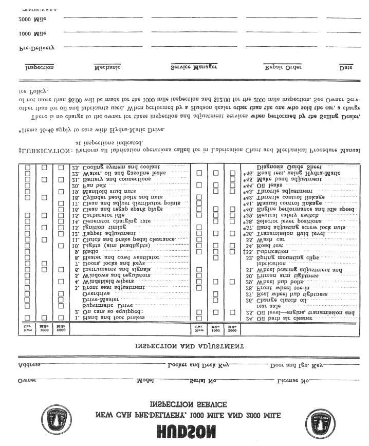
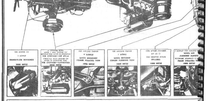
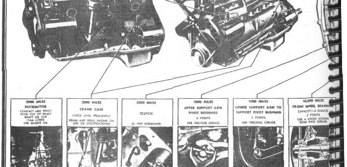
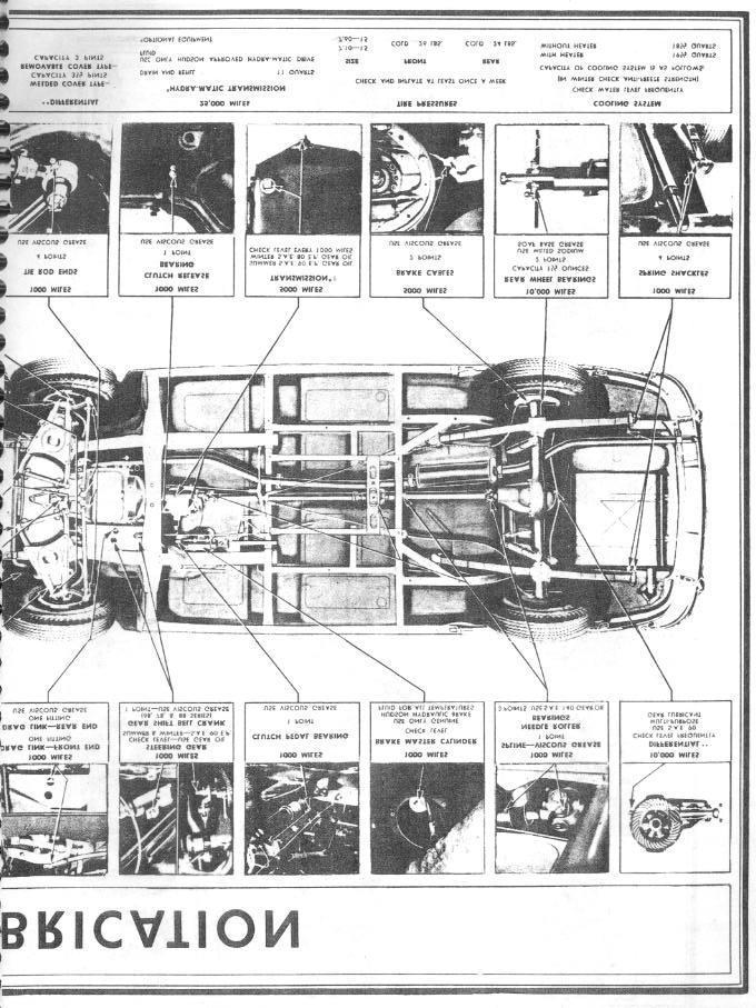
11 LUBRICATION 1-1 The present day high speed driving, fast acceleration, and precision fitted engine parts have placed engine and chassis lubrication in the category of highly specialized services. A definite plan of application is necessary to provide the various working surfaces with the right amount of the correct lubricant at the proper time. Contrary to general belief, one type of lubricant will not suffice to all applications. Varying load demands and operating conditions call for different types of lubricants. Authorized Hudson Dealers have been provided with a Lubrication Chart covering correct factory lubrication SECTION 1 LUBRICATION specifications, and a definite plan of application. Observance of this chart and its requirements will be definite assurance of customer satisfaction and goodwill. A copy of the Lubrication Chart is also included in this manual. Additional helpful information regarding the lubrication requirements are given in the Lubrication Schedules and the following paragraphs. NOTE: The lubricants used at the time of assembly are of the best quality and need not be changed until the recommended change period shown in the Lubrication Schedule. LUBRICATION SCHEDULES 500 Miles Drain the original engine oil at 500 miles and refill with a good grade of oil of the viscosity rating shown in the temperature and viscosity illustration, Figure 3, Page 6. For engine oil capacities of six and eight cylinder engines refer to Figure 1 - -Lubrication Chart and Capacities-- Page 10. 1,000 Miles Viscous Chassis Lubricant Points Drag Link 2 Upper Support Arm Eccentric Bushing. 2 Upper Support Arm Pivot Bushing 4 Lower Support Arm Pivot Bushing. 4 Lower Support Arm Support Bushing 2 Center Steering Arm Pivot Bearing 1 Tie Rod End 4 Points Steering Spindle Pivot Pins 2 Gear Shift Bell Crank Pivot 1 Clutch Pedal Bearing 1 Clutch Throwout Bearing 1 Universal Joint Spline 1 Rear Spring Shackle Bushing 4 Engine Oil Points Engine Check Oil Level Door Hinge 4 or 8 Gasoline Tank Filler Door Hinge and Spring 3 Points Rear Compartment Door Striker 4 Rear Compartment Latch Rod 2 Hood Hinge 8 Windshield Wiper Pulleys 4
12 1-2 LUBRICATION FIGURE 1
13 LUBRICATION 1-3
14 1-4 LUBRICATION

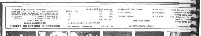
15 LUBRICATION 1-5 WATER RESISTANT LUBRICANT Windshield Cables at Pulleys Door Check Arms Courtesy Light Switch Door Lock Bolt and Slide Door Striker Rear Compartment Door Hinge Points 4 2 or 4 2 or 4 2 or 4 2 or 4 2 Rear Compartment Door Latch and Striker Hood Prop Hood Upper Lock Hood Lower Lock Hood Lower Lock and Control Wire Points GEAR LUBRICANT Transmission Overdrive Check Level Steering Gear Check Level S.A.E. 80 Winter S.A.E. 90 Summer Check Level Check Level Check Level Rear Axle Check Level Multi -Purpose Gear Lubricant-S.A.E. 90 Check Level Universal Joint Needle Rollers - 3 Points Gear Oil - S.A.E. 140 Check Battery Electrolyte level and gravity. Water or Anti-Freeze Check Coolant Level and Anti-Freeze strength. Hudson Hydraulic Brake Fluid Check Brake Master Cylinder fluid level. Hydra-Matic Transmission - Check Level 2,000 Miles Perform operations included in 1,000 mile lubrication, in addition to the following: FIGURE 3 Hydra-Matic transmission fluid level should be checked when a chassis lubrication is being performed. The procedure for checking fluid level is included on pages 41 and 42 in Hydra-Matic Section No. 11. Engine Oil Engine Generator Distributor Air Cleaner - Standard Air Cleaner - Oil Bath Throttle Operating Linkage Oil Filler Pipe Cap Brake Operating Linkage Hydra-Matic Linkage Drain Oil and Refill 2 Points 4 Points Wash and re-oil Clean and add new oil All Joints Wash and re-oil All Joints Lubricate using light engine oil
16 1-6 LUBRICATION 5,000 Miles Perform operations included in 1,000 mile and 2,000 mile lubrications, in addition to the following: Hudsonite Clutch Compound Clutch Drain and Refill E.P. Gear Lubricant--S.A.E. 80 Winter, S.A.E. 90 Summer Transmission Drain and Refill Overdrive Drain and Refill Multi-Purpose Gear Lubricant--S.A.E. 90 Rear Axle Drain and Refill Viscous Chassis Lubricant Brake Cables Clean and Lubricate Oil Filter Renew Cartridge 10,000 Miles Perform operations included in 1,000 mile, 2,000 mile, and 5,000 mile lubrications, in addition to the following: Hydra-Matic Oil Level Indicator Air cleaner in oil level indicator cap should be cleaned every 10,000 miles or twice a year. Viscous Chassis Lubricant Rear Spring Covers Inject lubricant with special lubricating clamp Sodium Soap Base Lubricant Front Wheel Bearings Rear Wheel Bearings Remove, Clean, and Repack Remove, Clean, and Repack 15,000 Miles Hydra - Ma t i c transmission fluid should be changed every 15,000 miles, instructions for draining and refilling are shown on Pages 55 and 56 of the Hydra-Matic Manual. IMPORTANT: When checking the level of the lubricant in rear axles and transmissions, make sure that the lubricant has stopped foaming. When car has been run for a considerable length of time, it should be permitted to stand long enough to allow the oil to reach the true level before checking. OIL FILTERS On cars equipped with oil filters the cartridge should be replaced at 5,000 mile intervals or when the oil shows evidence of becoming dirty. When replacing the cartridge, be sure to use a new cover gasket and see that it seats properly to prevent oil leaks. BREAK-IN OIL If a tune-up oil or break-in oil is used make sure it is made by a reputable manufacturer, who will guarantee his product as containing no harmful ingredients.

17 LUBRICATION 1-7 ENGINE OILING CIRCUIT Normal oil pressure causes the plunger to recede and the circuit is broken. 8 CYLINDER Engine lubrication is by the Duo-Flow system which delivers oil in direct ratio to engine speed to bearing surfaces immediately from the first turn of the crankshaft. The oil is drawn from the oil pan by the double acting oscillating plunger type pump driven by the camshaft. The oil is drawn from the sump and forced through oil lines to the front and rear of the engine where it is delivered to the front and rear troughs in the oil pan upper tray. The oil is then picked up by the connecting rod dippers and distributed to the interior working surfaces through splash and a system of channels which convey it into wells over the crankshaft and camshaft bearings and timing gear compartment. Overflow oil running down the crankcase walls is diverted by drains in the oil pan tray into adjacent splash troughs until it reaches the center of the engine. At this point, it is returned through the opening in the tray, then to the main oil supply where it is cooled and screened before again being used. The new design oil pan with sump at rear is provided with a floating type screened intake. This permits only the cleanest oil to be drawn off by the pump. Both rear and front main bearing caps are packed to prevent oil leakage and a large oil retainer collects oil from the outside of the rear main bearing and returns it to the oil pan. The oil return tube leading from the rear main bearing to oil pan has a floating disc or "flapper valve", pinned on the lower end to prevent any loss of oil on extreme grades or on quick stops. An oil check valve is mounted at the rear right side of crankcase, through which the oil from rear lead pipe of oil pump flows and controls a light on the instrument panel. A spring loaded, movable cup shaped plunger lies in the path of the oil flow. When oil pressure is too low, the plunger completes an electric circuit and lights the red dash signal. FIGURE 4 OILING CIRCUIT 6 CYLINDER Full pressure lubrication to bearings of the engine is maintained by a rotor type oil pump mounted on the right side of lower crankcase and driven from a worm gear on the camshaft. Oil is drawn by the suction side of the pump through a pipe connecting with a floating screen in the sump, Figure 4. The oil pump parts consist of an inner and outer rotor, a shaft, and the body and cover. Outstanding characteristics of the pump are longer life and high pressure maintained at low speeds. Oil pressure is regulated by a built-in nonadjustable release valve and spring accessible through a plug at the left rear side of the engine.

18 1-8 LUBRICATION When starting the engine the release valve has moved to a position that closes the oil passageway to the oil filter and allows full pump flow direct through the main oil gallery extending the full length of the crankcase. This oil gallery is intersected by drilled leads to main and camshaft bearings and valve lifters. Oil pressure is supplied to the connecting rod bearings through the drilled crankshaft. The angular hole drilled through the upper half of the connecting rod bearing shell seat is for the purpose of lubricating the cylinder walls. A tube fitted in the front end of main oil gallery directs a small pressure stream of oil at the point where chain meshes with crankshaft sprocket. Returned oil flows over the wide shallow portion of the oil pan where it is cooled before reaching the sump. CHECKING ENGINE OIL LEVEL An engine in normal operating condition is expected to use some oil, and it is therefore not unusual to add oil between change periods. Its rate of usage is governed by the individual engine and is dependent on operating speeds, temperatures, and the viscosity and quality of the oil used. The oil level should be checked each time fuel is added. The gauge is located on the left side of the engine and is marked to show the "Oil Level Range" and the "Low Mark", F 5 The oil measuring gauge seats on a tube pressed in the crankcase at left rear side. A sealed pressure type oil signal switch mounted just above the oil pump and connected with the main oil gallery, is wired to the dash oil signal light. Should oil pressure drop below approximately 13 pounds, the circuit is completed and lights the red dash oil pressure signal. Capacity of the oil pan is 7 quarts for refill and 7-1/2 quarts when pan is removed for cleaning. ENGINE OIL CAPACITIES The total engine oil capacity is 7-1/2 quarts for six cylinder and 8 quarts for eight cylinder engines. When the oil is drained in the conventional manner, the refilling quantity is 7 quarts for both six and eight cylinder engines. When the oil pan is removed for cleaning or during service work, two quarts should be placed in the oil pan tray of eight cylinder engines before the pan is Installed. The remaining seven quarts should then be placed in the pan through the crankcase filler opening. In six cylinder engines the entire quantity is poured through the crankcase oil filler pipe. FIGURE 5 For normal operation the oil level is satisfactory when it is within the "Oil Level Range". For high speed operation the level should be maintained at the full mark which is the top line on the "Oil Level Range". To make an accurate check, wait a minute or two after shutting off the engine to permit the oil to drain back into the oil pan. Approximately three and one-half quarts of oil are required to bring the level from low to full in both six and eight
19 LUBRICATION 1-9 cylinder engines. If the level happens to be low and the speedometer indicates that the oil change period is near at hand, it is more economical to have the oil changed at that time. The oil refiners or marketers supplying engine oils are responsible for the quality of their products and their reputation, is the car owners best assurance of receiving high-grade lubricants. WHEN TO CHANGE ENGINE OIL The oil which is placed in the engine at the factory is satisfactory for the first 500 miles of operation and should then be changed. TYPES OF OIL The various types of oil marketed for engine lubrication have been defined by the American Petroleum Institute as follows: Thereafter, at intervals of 2,000 miles, the oil pan should be drained and refilled. If the car is operated in dusty areas or for short distances at low speeds during cold weather, foreign matter and sludge will accumulate and the oil should be changed more frequently. However, the actual change period is largely dependent on the individual driving circumstances. The oil is drained by removing the plug at the rear of the oil pan. To insure complete draining, it is important that the operation be performed while the engine is warm. Recommend to your customer that it is a good practice to remove the oil pan at least twice a year, preferably in the spring and fall to permit thorough cleaning of the screens and pan. CAUTION: The use of flushing oil or compounds is not recommended. However, in the event they are used, it will be necessary to remove the oil reservoir and thoroughly clean it out before Installing the new oil. THE PROPER ENGINE OIL TO USE The use of high-grade engine oil of the correct type is of the greatest importance in obtaining maximum engine performance. Always select oils from well-known and dependable brands, and of the proper viscosity to suit the seasonal and customer driving requirements. REGULAR MOTOR OIL - This term is used to designate a straight mineral oil. Oils of this type are generally suitable under moderate driving conditions. PREMIUM MOTOR OIL - This term is used to designate an oil having proved oxidation, stability, and bearing corrosion preventative properties. Oils of this type are generally suitable for use where operating conditions are such that regular oils do not give satisfactory service. HEAVY-DUTY MOTOR OIL - This term is used to designate an oil having proved oxidation, stability, bearing corrosion preventative properties and detergent characteristics. Oils of this type are generally suitable for use in both highspeed diesel and gasoline engines under heavy-duty service conditions. It is most important that the oil should have the ability to flow at low temperatures to permit easy starting, and at the same time afford adequate lubrication when the engine is at normal operating temperatures. The oil selected should be based on its ability to perform these two functions at the lowest anticipated temperatures expected before the next oil change period. The illustration, Figure 3, will be helpful in making this selection. NOTE: Kerosene should be added only when temperatures below -10 are expected for long periods.
20 1-10 LUBRICATION OIL DILUTION The lubricating oil in the crankcase is sometimes thinned or diluted due to gasoline leaking by pistons and rings and mixing with the oil. This leakage usually occurs during the "warming-up" period when the fuel is not thoroughly vaporized and burned. The Hudson engines are equipped with automatic devices that are designed to reduce oil thinning caused by raw fuel dilution. In order to assist the engine to warm up as quickly as possible the water temperature is controlled by a thermostat which prevents complete water circulation for cooling until a predetermined temperature has been reached. Another thermostat automatically controls the opening of a valve mounted inside the exhaust manifold to vary the amount of heat applied to the walls of the intake manifold. This item combined with the previously mentioned features greatly reduces the cold running periods. Outlet: The crankcase outlet ventilator is mounted at the rear valve cover on both 6 and 8 cylinder engines. In cases of excessive oil usage or leaks at rear main bearing, check the outlet breather pipe. This pipe may be plugged with dirt, and on the 8 cylinder engines, it may be restricting at the valve cover baffle. DO NOT tighten the breather outlet pipe attaching bolt more than 2-3/4 to 3-1/4 torque pounds. Engine Oil - Dry U.S. Quarts Imperial Quarts Engine Oil-Refill U.S. Quarts Imperial Quarts Clutch U.S. Pint Imperial Pint CAPACITIES 6 Cyl. 7-1/2 6-1/ /3 1/4 8 Cyl / /3 1/4 As a further safeguard, the Hudson crankcase ventilating system is utilized to expel from the crankcase any ordinary collection of water or fuel vapors. In this system the rotating crankshaft acts as a blower to force such vapors from the case via the breather tubes on the valve chamber cover. Transmission (Single Lever Type) U.S. Lbs Imperial Lbs Transmission (Double Lever Type) U.S. Lbs 2-1/4 Imperial Lbs. 2-1/4 Transmission & Overdrive (Single Lever Type) /4 2-1/4 Inlet: CRANKCASE VENTILATOR The crankcase ventilator inlet is part of the crankcase oil filler cap assembly on the 6 cylinder engines. This filler cap contains copper gauze which filters the air passing into the crankcase. The cap should be inspected every time oil is added and should be thoroughly cleaned at least every 5,000 miles. Clean in gasoline and blow dry. Re-oil the filter element gauze. 3 U.S. Lbs. 3 Transmission Imperial Lbs. & Overdrive (Double Lever Type) U.S. Lbs. Imperial Lbs Hydra-Matic Refill U.S. Quarts Rear Axle U.S. Lbs. Imperial Lbs. 3-1/4 3-1/ /2 3-1/2 3-1/4 3-1/ /2 3-1/2
21 ENGINE TUNE-UP 2-1 SECTION 2 ENGINE TUNE-UP SPECIFICATIONS Cylinder Compression Vacuum, Intake Manifold Valve Tappet Clearance (Hot), 6 and 8 Cylinder: Intake Exhaust Battery Specific Gravity Starter Motor: Cranking Voltage Cranking Amperage (Engine Warm) Stall Test: Volts Amperes Torque Condenser Capacity Coil Amperage Draw: Engine Stopped Engine Idling Distributor: Point Gap Cam Angle (Dwell) Spring Tension Vacuum Advance: Generator Output: RPM Cold 870; Hot 950 RPM Cold 1800; Hot 2000 Voltage Regulator: Cutout Relay points Close Cutout Relay points Open Voltage Regulator Operates Spark Plug Gap 032" Fuel Pump Pressure: Carter A.C. Fuel Pump Vacuum Fuel Pump Volumn Carter A.C. Carburetor: Float Setting Pump travel Idle Adjustment Climatic Control MODEL 4B 5.0 Volts, 68 Max. Amps. Approximately 160 Amps at 120 RPM 2.0 Volts 280 Max. Amps 4.4 Min. Ft. Lbs mfd 5.0 Amps Amps MODEL 4B.020" oz. 5 at 12" Hq. 10º at 1200 RPM MODELS WA1-649-S WA1-968-S WA1-990-S 1/2" 16/64" 1/2 to 1-1/2 turns open Set at index WA1-649-S WA1-968-S One point lean WA1-990-S 5B, 6B, 7B 020" oz 4 at 8" Hq 9 at 2000 RPM WGD-776-S 3/16" 5/16" 1/2 to 1-1/2 turns open Set at index All Models Minimum, 100 lbs " Hq. Six Cyl.-.010"; 8 C yl.-.008" Six Cyl.-.012"; 8 Cyl " MODELS 5B, 6B, 7B and 8B 5.0 Volts, 65 Max. Amps. Approximately 160 Amps at 120 RPM 2.0 Volts 335 Max Amps 6.0 Min. Ft. Lbs mfd 4.5 Amps 2.5 Amps 8B 017" oz 40 at 16" Hq 17.5 at 1700 RPM 6.4 Volts 0 amps. 8.0 Volts 35 amps Volts Volts (after 15 amp. charge) or amps. Reverse Current Volts 35 Amperes at 70 F. 032" 3-1/2-4-1/2 lbs. 3-4 lbs. 6" Hq. 1 quart RPM 1 pint RPM WGD-773-S 3/16" 5/16" 1/2 to 1-1/2 turns open Set one point lean


22 2-2 ENGINE TUNE-UP ENGINE TUNE-UP Modern high compression, high speed engines require periodic diagnosis and adjustments to maintain peak performance and economical operation. A periodic engine tuneup will assure this maximum engine performance, fuel economy and dependability. Accurate testing equipment in good condition is essential to proper diagnosis. If a master tester is used, the battery of the tester should be maintained in a fully charged condition. The tune-up procedure is arranged in the usual order of performance. Only by performing the operations in the following procedure and adhering to the limits and specifications given therein is it possible to obtain the maximum performance and economy built into Hudson engines. BATTERY Many of the tests involved in tune-up are dependent upon a battery in good condition. If the battery is below standard, it should be recharged, or replaced with a fully charged battery before the tune-up. BATTERY SPECIFIC GRAVITY: Check the battery specific gravity with a hydrometer, Figure 1. A battery when fully charged should show specific gravity at 70 F. A uniform hydrometer reading below at 70 F. indicates a low battery that should be recharged. If gravity varies more than 25 points between cells, battery should be recharged and tested under load. CAUTION: Electric storage batteries give off highly inflammable hydrogen gas when being charged and continue to do so for some time after receiving a steady charge. Do Not allow sparks or an open f la m e near the battery, especially in the vicinity of the battery vent caps. Before doing any work around the battery, a metallic contact between the car bumper and the ground should be made to remove any possibility of a static charge causing a spark in the vicinity of the battery. BATTERY LOAD TEST: Battery may be tested under load by connecting a voltmeter across the battery terminals and cranking the engine. Battery is satisfactory if it will crank the engine at a good speed for 1/2 minute and the voltage does not fall below 4-1/2 volts. Slow cranking speed or lower voltage may be due to high resistance in the starter circuit. Check cables and retest. (DO NOT CRANK MORE THAN 1/2 MINUTE AT A TIME ). A standard cell tester may be used to make the load test. The cell tester has a shunt across the terminals which places each cell, under load. Each cell should show 1-1/2 volts or over, and the variation between cells should not exceed.15 volts. FIGURE 1 FIGURE 2
23 ENGINE TUNE-UP 2-3 If a starter-battery tester, Figure 2, is available, make the load test as follows: 1. Connect ammeter and voltmeter positive leads to the battery positive terminal post. 2. Connect ammeter and voltmeter negative leads to the battery negative terminal. 3. Turn the voltmeter knob to the 15 volt position; then turn the starter-battery knob to the battery position (clockwise) until the ammeter shows a 300 ampere discharge. With the ammeter reading 300 ampere discharge for 15 seconds the meter should read 4 volts or more. Replace battery if voltage is lower than 4 volts. NOTE: It is very important that an even discharge load is placed on the battery while testing the individual cells. 2. Apply the voltmeter leads across each cell in turn and note the individual cell voltage under load. A variation of more than.2 volt between the highest and lowest reading cells indicates a weak cell CRANKING VOLTAGE: STARTER MOTOR 1. Connect the negative voltmeter lead to the starter switch terminal (where the battery to starter cable is connected), Figure After completing test, quickly turn starter-battery knob to the "off" position and disconnect test leads. CAUTION: Do not leave the high discharge load on the battery for periods of more than 15 seconds. If a Starter-Battery Tester is not available, a voltmeter can be connected across the battery terminals while cranking the engine with the star ting motor. The battery is in good condition if the starter cranks the engine at a good speed for 1/2 minute and the voltage does not fall below 4-1/2 volts. Do Not crank more than 30 seconds without allowing starter motor to cool. NOTE: A slow cranking speed or voltage lower than 4-1/2 volts indicates a weak cell or high resistance in the connections to the starter. Check battery cables and connections and repeat the " Load Test". INDIVIDUAL CELL TEST: To use a Starter-Battery Tester: 1. Connect the positive ammeter lead to the battery positive post and the negative ammeter lead to the battery negative post. Turn the voltmeter knob to the 5 volt position and turn the starter-battery knob until ammeter shows a 300 ampere discharge. FIGURE 3 2. Connect the positive voltmeter lead to the engine for a ground. If a starter-battery tester is used, turn the selector knob to the 15 volt position. 3. With the ignition key off, engage the starter motor and note reading on the voltmeter. The cranking voltage should read 5 volts or more. CAUTION: Crank engine intermittently (not more than 30 seconds) to prevent starter motor from overheating. 4. If the voltmeter reading is less than 5 volts, check the battery and engine ground straps, starter cable and the starter solenoid to determine the cause for the low reading.
. 4. If more than.")
24 2-4 ENGINE TUNE-UP BATTERY AND ENGINE GROUND STRAPS: 1. Connect the voltmeter positive lead to the battery ground terminal post, Figure Connect the voltmeter negative lead to engine ground and a jumper to the frame. 3. With ignition off, crank engine and make voltmeter reading, (should not be more than.2). 4. If more than.2, check ground strap connections from battery to frame and from engine to frame. Replace FIGURE 5 AMPERAGE DRAW TEST: 1. Turn battery starter tester knob to "off" position. 2. Turn the voltmeter "selector switch" to the 15 volt position and connect test leads, Figure 6. defective ground straps. STARTER CABLE: FIGURE 4 1. Connect the positive voltmeter lead to the "Bat" terminal of starter and negative lead to negative battery post. 2. Crank engine again (ignition off). Now if voltmeter reading is more than.2, check for loose connections or frayed cables. STARTER SOLENOID: 1. Connect negative voltmeter lead to "Bat" terminal of starter solenoid switch and positive lead to motor terminal of the solenoid switch, Figure Close the solenoid electrically to crank the engine; and if the reading is more than 0.2 volts, replace the solenoid switch. FIGURE 6 3. Press starter switch and crank engine for approximately 15 seconds and note the "exact" reading on voltmeter. 4. Release Remote Control Starter Switch and turn Starter- Battery Tester knob clockwise until the voltmeter reads "exactly" the same as when cranking the engine. Test ammeter reading should be 140 to 160 amperes (engine warm).

25 ENGINE TUNE-UP After completing amperage draw test, turn tester control knob to " OFF" position. NOTE: Excessively high readings will indicate a short in the starting motor circuit or an excessive drag on the motor due to a bent armature shaft or the field coils touching the armature. Low readings indicate excessive resistance in the circuit caused by loose connections, worn brushes, or weak brush spring tension. CYLINDER BALANCE TEST The Cylinder Balance Tester compares the evenness of the power output of each cylinder in the engine. To isolate one weak cylinder, short out half the cylinders. The half giving the lower reading will include the weak cylinder. Air bubbles prevalent in the radiator filler neck (radiator filled with coolant to the over-flow pipe) indicates a leaking cylinder head gasket, cylinder head or internal cracks in the water jackets. An extreme blow-by at the oil filler pipe indicates defective piston rings. (Compression pressures by-passing the piston rings). COMPRESSION Compression should be checked with a reliable compression gauge and with the engine at operating temperature (ignition switch off ). 1. Remove foreign matter around spark plugs. Loosen spark plugs about one turn to break free any accumulated carbon, start the engine and accelerate to 1000 R.P.M. to blow out the carbon. Stop the engine and remove the spark plugs placing them in the order that they were removed. FIGURE 7 1. Connect the vacuum gauge and tachometer as shown in Figure 7, and set the throttle until engine is running at 1500 R.P.M. 2. Ground the master clip of the cylinder balance tester and connect individual leads to spark plugs and 5. Engine will now be running on cylinders 1 and Note the reading on the vacuum gauge. Make the same test on each pair of cylinders in the following sequence. 6 cylinder 1-6, 2-5, cylinder 1-8, 3-5, 4-7, 2-8 NOTE: A variation of more than 1 inch of vacuum or 40 R.P.M. between pairs of cylinders being tested indicates either a defective plug or unequal compression in a cylinder. NOTE: Starting and accelerating the engine after the plugs are loosened is very important to remove loose carbon and prevent the carbon flakes falling on the piston crown and around the valve. 2. Insert the compression gauge in each spark plug hole in turn and crank engine with J-2679 Remote Control Switch. Crank engine for at least 4 compression strokes. Note reading on the first as well as final stroke. 3. Compression at each cylinder should be at least 100 pounds. Compression between cylinders should not vary more than 10 lbs. NOTE: If the compression gauge moves up in jerky steps of 10 or 20 pounds at a time, it generally indicates a sticking or leaking valve. If two adjacent cylinders show low compression readings, check for a leaking cylinder head gasket or loose cylinder head.

26 2-6 ENGINE TUNE-UP 4. If the compression reading is low, inject a small quantity of light engine oil in the cylinder bore to seal the rings and recheck. Now if the compression is higher, worn piston rings are indicated. 5. If the compression remains low on the second test, the valve operation is faulty or the piston may be cracked or damaged. Correct any unsatisfactory condition found during the compression test before continuing with the engine tune-up. 6. Examine spark plug wires for loose terminals, cracked or broken insulation. Replace defective wires. NOTE: Spark plug condition often indicates other engine troubles. See" Electrical Section." SPARK PLUGS Upon satisfactory completion of the compression test, inspect, clean and adjust spark plugs. 1. Spark plugs with burned, blistered, or cracked porcelains, or with pitted or burned electrodes, should be replaced with new plugs of the same type. For cast iron and aluminum cylinder heads, use Champion H-8 spark plugs. 2. Clean the plugs with an approved spark plug cleaner. 3. Adjust spark plug gaps to.032" using a bending tool and wire loop gauge, Figure 8. FIGURE 8 VACUUM TEST: FIGURE 9 An engine in good condition will show a steady, or slightly fluctuating, high vacuum reading of from 18" to 21". Vacuum readings are affected by altitude. Over 2000 feet the vacuum gauge will show about one inch lower for each thousand feet feet feet feet feet feet feet feet feet ,000 feet 18" to 21" 17" to 20" 16" to 19" 15" to 18" 14" to 17" 13" to 16" 12" to 15" 11" to 14" 10" to 13" 4. Install NEW gaskets on the plugs and replace plugs in cylinder head. 5. Tighten plugs finger tight then tighten with a torque wrench, to 25 to 30 foot pounds. (If torque wrench is not available, tighten 3/4 of a turn). 1. Remove wiper hose at connection at intake manifold and connect vacuum gauge hose to intake manifold. (If the engine has a combination fuel and vacuum pump, disconnect the booster pump line at intake manifold.) 2. Check carburetor and intake manifold attaching nuts for tightness.


27 ENGINE TUNE-UP 2-7 Connect one lead of tachometer to the distributor primary terminal and the other lead to engine for ground, Figure 9. Adjust carburetor to obtain a smooth idle at 540 to 580 R.P.M. (If car is e quipped with Hydra-Matic Transmission, set idle at Vacuum readings at sea level may be interpreted generally as follows: " Steady or with slight fluctuation: Engine in good condition. 15" Steady: Incorrect ignition timing. 10" Steady: Incorrect Valve timing or burned valves " Fluctuating: Sticking valve s or compression leak " Drifting: Carburetor too rich or too lean. Any number of engine conditions may cause the same action of the vacuum gauge. Exact cause must be established by elimination. TAPPET ADJUSTMENT: To adjust tappets on six or eight cylinder engines, proceed as follows: 1. Raise front end of car and place stand jacks under frame crossmember. 2. Remove the right front wheel. 3. Remove the three headlight wires from terminal block to permit fender side dust shield removal. 4. Place a support below the hood and remove the top (right side) hood prop bolt to allow hood prop to re main attached to fender side shield. 5. Remove the twelve 1/4" - 20" hex bolts on the f e n d e r side dust shield and remove dust shield down and out under the fender. 6. From under the fender, reach up and remove the front tappet cover bolt. 7. Remove the rear tappet cover bolt and the breather pipe. Remove the rear tappet cover by sliding cover forward and out. VALVES AND TAPPETS: FIGURE 10 Check the valve tappet clearance when engine is at normal operating temperature, Figure 10. The intake and exhaust valve clearances are as follows: All 6 Cylinder 8 Cylinder Intake.010".008" Exhaust.012".010" 8. Remove the lower breather pipe bracket at engine rear end plate and remove breather pipe. 9. Adjust tappets. After tappet adjustment has been completed reinstall parts. NOTE: Use care when tightening the rear tappet cover and breather pipe attaching screw on eight cylinder engines, so breather pipe will not bottom against valve cover inner baffle and restrict ventilator. Tighten to 3 pounds torque.


28 2-8 ENGINE TUNE-UP DISTRIBUTOR 1. Remove the distributor cap from the distributor and thoroughly clean and examine the cap. Replace the cap if it has hairline cracks, carbon runners and badly burned or corroded contact inserts. 2. Clean the spark plug cable sockets using KMO-230 Distributor Cap Terminal Cleaner. Clean any corrosion from the metal secondary contacts on the underside of the cap. If these contacts are badly burned or scored, replace the cap. NOTE: If burning exists on the horizontal face of the inserts or on t op of the rotor metal strip, it indicates that the metal strip of the rotor is too short and the rotor should be replaced. 3. Clean and inspect the rotor. Replace the rotor if the insulation is cracked or has carbon tracks, or if the metal strip is badly burned. CONTACT POINTS: 1. Inspect, clean and adjust the distributor breaker points. Replace burned or corroded points. Do not try to hone pitted contact points as refaced contacts do not have the finish for satisfactory performance. FIGURE 11 NOTE: Contact point adjustment is made by first loosening the clamp screw (B) Figures 11 and 12, holding the stationary contact plate, then turn the eccentric adjusting screw (D) to move the stationary contact point. Tighten clamp screw when correct gap is secured. NOTE: If points are badly pitted, check the condenser for over or under capacity. See "Electrical Section - Condenser". 2. When new contact points are Installed be sure they are properly aligned and that they make contact near the center of the contacts. Bend the stationary contact bracket to secure proper alignment. Do Not Bend The Breaker Arm. Adjust the breaker point gap.020" for 6 cylinder distributors and.017" for 8 cylinder distributors. Breaker Arm fibre rubbing block should be on high pointof the distributor cam when checking adjustment of breaker points. 3. Apply a few drops of light engine oil to the wick located at the top of the distributor shaft, to the contact arm pivot and to the lobes of the cam. Do Not over-oil. FIGURE 12
, Figures 11 & 12, attaching breaker arm spring to plate and move end of spring in or out of clip as necessary.")
29 ENGINE TUNE-UP 2-9 BREAKER ARM SPRING TENSION: 1. Hook a spring scale to the breaker arm at the contact and pull at right angles to the contact surface. Tension should be 17 to 20 ounces just as the points open. 2. Adjust spring tension by loosening screw (A), Figures 11 & 12, attaching breaker arm spring to plate and move end of spring in or out of clip as necessary. NOTE: If the tension is too weak the contacts will chatter at high speed giving poor engine performance, while if the tension is too strong, excessive wear of the cam and breaker arm rubbing block will result. block bar indicates high resistance in the distributor ground circuit. NOTE: High distributor resistance will decrease primary current draw, thus reducing coil output. DISTRIBUTOR DWELL TEST: 1. Connect Tach-Dwell Tester negative lead to the distributor primary terminal and the positive lead to ground. (ReInstall distributor cap, spark plug wires and distributor primary wire.) DISTRIBUTOR POINT RESISTANCE TEST: 1. Using a Tach-Dwell unit, connect the negative lead to the distributor primary terminal and the positive lead to a ground, Figure 13. FIGURE 14 FIGURE Turn ignition key on. Turn the dwell control knob to "Calibrate" position and crank the engine a fraction of a revolution at a time until the highest reading is obtained on the Dwell-Meter. The highest reading will occur when the points are entirely closed. The meter should read inside the b lock bar at the right end of the scale (Point Resistance). A reading outside the 2. Turn switch to "Calibrate" position and adjust Dwell Regulator knob until meter reads to "Set Line". Turn the Dwell Switch knob to the 6 lobe position for six cylinder engines and 8 lobe for 8 cylinder engines. Turn Tachometer Selector Switch to the 5000 R.P.M. position. 3. Start engine and run engine at idle speed. Tachometer w ill indicate engine R.P.M. Dwell Meter will indicate the dwell angle or degrees of dwell of the distributor points. The d w ell angle on the six cylinder engine is 38 degrees, breaker points
30 2-10 ENGINE TUNE-UP set at.020", and 27 degrees on the eight cylinder, breaker points set at.017". Increase engine speed to 2000 R.P.M. Dwell Meter reading should not vary more than 2 degrees. NOTE: If the dwell angle is too great, the contact point gap is set too close. If the dwell angle is too small, the contact gap is too wide. An erratic reading of the Dwell Meter will indicate faulty contact, a faulty breaker plate, or worn distributor shaft and bearings. A change of dwell angle when accelerating or decelerating the engine will indicate a faulty breaker plate, bearing or support plate. CONDENSER TEST 1. Block distributor points open with a piece of fibre. Disconnect the primary lead wire at the distributor. 2. Check condenser lead to see that it is not frayed or broken and is connected securely to breaker arm clip. Condenser mounting screw must make tight ground to breaker plate. Ground wire from breaker plate to sub-plate must be securely connected. 3. To calibrate the condenser tester, connect the two condenser test leads together Turn the condenser control knob to the "Microhm" position and allow the tester to warm up for one minute. Then turn the control knob to read on the set line. 4. After calibrating the condenser tester leave switch in "Microhm" position and connect the red lead to the distributor primary terminal and the black lead to the distributor housing, Figure With the control knob turned to the "Michrohm" position, the meter should read in the blue bar marked "MIC" at the right side for satisfactory condenser circuit resistance. If the reading is not in the blue bar, move grounded lead of condenser tester to the body of the condenser. If reading improves, condenser is not properly grounded. Move condenser pig tail lead about. If a deflection of the meter is noted, lead is making poor contact. 6. Turn the condenser switch to the. "Micro- farad". The meter should read 20 to 25 microfarads for both six and eight cylinder engines. 7. Turn the condenser switch to the "Meg-ohm" position. Meter should now read in the blue bar at left side marked "MEG" f o r satisfactory condenser insulation. If the meter reads in the red bar or over to the extreme right, replace the condenser. FIGURE 15 NOTE: When making the above checks, the condenser should be at operating temperatures.
31 ENGINE TUNE-UP 2-11 VACUUM ADVANCE ADJUSTMENT: Vacuum advance should be checked on a distributor test fixture that has a controlled source of vacuum and a vacuum gauge. 1. Place distributor in the distributor clamp and tighten securely with the hand wheel at the right side of clamp. 2. Adjust the vertical screw so distributor shaft fits down into the drive chuck. 3. Use special wrench to tighten the distributor shaft in the drive chuck. 4. Connect red tipped distributor lead to binding post at the side of the distributor. 5. Attach vacuum pump connection. 6. Turn cam lobe switch to Battery Check position. Tachometer indicating hand should read in bar at right end of scale. 7. Test distributor point spring tension scale. The spring tension is 17 to 20 ounces on both the six and eight cylinder distributors. 8. Turn on battery switch at left side of tester head. 9. With cam lobe switch in the 6-lobe position and distributor contact points closed, the dwell meter indicating hand must read in the black bar for satisfactory point resistance. If the reading is in the red band, it indicates dirty contact points, loose connections, or resistance within the distributor circuit. 10. Turn the motor drive switch to right hand rotation and adjust the speed control crank until the Tachometer reads 200 R.P.M. 11. Adjust the distributor contact points until proper degrees of dwell is indicated. 12. Turn graduated degree ring until the arrow flash appears at Then check to see if all flashes appear at 60 degree intervals for the Hudson Six and at 45 degree intervals for the Hudson Eight. If the f lashes do not appear to within one degree of the respective angles, it indicates an inaccurate cam. 14. Turn vacuum switch to the "ON" position. 15. Set degree ring so arrow will be on zero at a most convenient point to read. 16. Adjust vacuum regulator to obtain correct reading on vacuum regulator for exact p o n t the vacuum advance starts to operate, and compare with specifications. Adjust the vacuum regulator to each specification and check the arrow flash on the degree ring. 17. Watch the arrow on the degree ring as the vacuum regulator is adjusted to the point vacuum advance starts to operate. Compare the reading with specifications and adjust the vacuum regulator to each specification and check the arrow flash on the degree ring. 18. If the degree indicated on ring is more than specified, the unit is advancing too quickly showing the return spring is too weak. 19. If the degree indicated on the ring is less than the specifications, the unit is advancing too slow ly showing the return spring is too strong. 20. Vacuum advance characteristics are varied by changing the spring pressure or by inserting or removing washers under the end of the spring in the vacuum chamber. AUTOMATIC ADVANCE CURVE: 1. Adjust speed control so that distributor will rotate at the lowest R.P.M. 2. Set degree ring so arrow will flash at zero at a point most convenient to read. 3. Increase distributor R.P.M. to correspond with specifications marked "Start". 4. Check the R.P.M. required to advance the arrow flash to the first specification given. NOTE: Be sure the advance is opposite the rotation of the distributor shaft. 5. Continue to check the advance curve R.P.M. against degree of advance and compare this with specifications.


32 2-12 ENGINE TUNE-UP 6. If the degree of advance on the degree ring is more than specifications call for at the same R.P.M., it indicates that the governor spring tension is too weak and the advance is too rapid. 7. If the degree of advance on the degree ring is less than specifications call for at the same R.P.M., the spring tension is too stiff and the advance is too slow. 8. Check the advance both up and down the speed range so that the sluggish action of the governor mechanism will be indicated and may be corrected by cleaning and lubrication. NOTE: Every 2,000 miles, lubricate contact arm pivot, wick top of shaft, cam lobes and 3 to 5 drops of medium engine oil at oiler. 3. With ignition switch on, turn Master Control Switch to "Coil Set" and adjust Coil Set Regulator knob until meter reads on proper "Set Line". 4. Turn switch to "Coil Test" position. The meter reading must be within the " Good Coil" band and hold steady to denote a good coil. A reading out side the "Good Coil" area or an erratic reading of 3 to 5 divisions inside "Good Coil" band indicates a bad coil. NOTE: If the coil meter does not read in the "Good Coil" band, remove the coil cap and connect test leads directly to the primary connections. After making direct connections to the coil, retest, and if the meter does not read in the "Good Coil" band, replace the coil. NOTE: Before to sting any ignition coil it should be brought to operating temperature. Follow testing e quip m e n t manufacturer's procedure for "Coil Heating". FIGURE 16 COIL COIL TEST: 1. Calibrate Coil Breaker Unit. 2. Disconnect the primary ignition lead at the distributor and the high tension lead from the coil. Connect red lead of Coil Breaker Unit to the primary wire disconnected from the distributor primary terminal, and the ground lead to the battery starter terminal, Figure 16. FIGURE 17 COIL SECONDARY RESISTANCE CHECK: 1. Calibrate Coil Breaker Unit by connecting the ground (Blue) and positive primary (red insulator) test leads together. 2. Turn master switch "On".


33 ENGINE TUNE-UP Turn tester switch to Dwell-Ohm position, and adjust Dwell-Ohm Regulator until meter reads on "Set" line. 4. After calibrating the Test Unit, separate the positive primary and ground test leads, connect the positive primary lead to the primary ignition wire which was removed from the distributor, Figure Insert the short test lead into the high tension post of the coil and connect the ground lead directly to the short test lead. IGNITION TIMING For average operating conditions, both six and eight cylinder engines should be set to fire at top dead center of the compression stroke at cranking speed. When the long mark before the UDC on the flywheel is lined up with the pointer on the rear engine support plate, Figure 19, No. 1 piston is at top dead center. Ignition timing may be accurately set by the use of a neon timing light as follows: 6. Meter should read from 2,000 to 10,000 OHM's resistance. If the meter reads outside this range, replace coil. SPARK PLUG MILLIAMPERE TEST: 1. Connect primary lead (Red Insulator) of the Coil Breaker Unit to engine for a ground, the other primary lead (Black Insulator) to the number one spark plug, Figure Run engine at idle speed, turn to switch to the Milliampere position and read Coil Meter Milliampere Scale. 3. The reading should be the same at each spark plug. A low reading (established on a comparative basis) may indicate a weak coil, excessive resistance either in the primary or secondary circuit, corroded terminals, or poor connections. NOTE: The six cylinder distributor cap has a built-in resistor. FIGURE Connect one lead of the power timing light to the No. 1 spark plug, the other lead to the negative terminal of the battery. 2. Place a chalk mark on the long timing mark on the flywheel, Figure 20. Loosen FIGURE 18 FIGURE 20
34 2-14 ENGINE TUNE-UP the distributor quadrant attaching screw and operate the engine at idle speed with the timing light aimed at the flywheel opening in the rear engine support plate. 3. With the engine idling properly, the light (spark) should occur when the dead center mark (chalked long line) on the flywheel is in line with the pointer at the opening of the rear engine support plate. 4. Tighten the quadrant screw and accelerate the engine. Chalk mark should move to the left of pointer as centrifugal governor advances the spark. If timing is off, make the necessary corrections by first loosening the distributor (advance arm) quadrant and rotate the distributor clockwise to retard and counter-clockwise for advance. If too much ping occurs or if the engine pings at higher speeds, timing should be retarded by rotating the distributor clockwise one graduation at a time. FAN BELT ADJUSTMENT: Adjustment of the fan belt is possible by moving the generator towards the engine or away on the generator adjusting bracket. 5. Increase engine speed. NOTE: The vacuum advance should be at full retard position, mechanical advance should advance readily when the engine speed is increased. Disconnect vacuum advance tube at distributor. 6. Ignition timing (spark setting) may be advance during continuous high altitude operation or with fuels of high octane rating of 80 or higher. To set the timing without a timing light, remove No. 1 spark plug and crank engine until No. 1 piston starts up on compression stroke. Continue cranking until long line on flywheel lines up with pointer. Loosen distributor quadrant screw and rotate distributor clockwise to the limit of the slot in the quadrant. Remove secondary wire from center of distributor cap and hold bare end of wire about 1/8" from the cylinder head. With ignition switch on, slowly rotate the distributor counter-clockwise just until a spark jumps from the wire to the cylinder head; then tighten quadrant screw. Correct ignition timing is indicated by a slight" ping" at about 15 MPH when accelerating at full throttle from 10 MPH in high gear. If no ping is heard, timing should be advanced one quadrant graduation mark at a time until the ping is heard. Under no circumstances should the pointer at the flywheel opening be more than one inch (first short mark) before the UDC mark when the spark occurs, Figure 20. FIGURE Loosen the two generator bolt nuts (D) and (E) and adjusting arm bolt (F), Figure Swing the generator away from the engine until the slack in the fan belt is such that the section between the water pump pulley and the generator pulley can be pushed down 3/4" below a straight edge laid across the pulleys as shown at (C), Figure Tighten generator attaching bolt nuts (D) and (E) after making the adjustment. NOTE: The fan belt is properly adjusted when the generator pulley can be just turned by hand. Do Not try to turn the generator pulley with the fan belt. GENERATOR OUTPUT CHECK: 1. Disconnect battery lead at voltage regulator "B" terminal; connect the ammeter negative lead to the regulator "B" terminal and the positive lead to the wire disconnected from the regulator, Figure Install a jumper from generator field terminal to a ground. 3. Momentarily raise the engine speed to approximately 1250 RPM, the reading on the ammeter should read 50 amperes minimum output.
35 ENGINE TUNE-UP 2-15 FIGURE 22 CAUTION: The engine MUST NOT be run for more than a few seconds while making the above test, due to the danger of burning out the generator. All lights and accessories must be turned off during the above test to prevent damage due to excessive voltage. NOTE: All generator tests should be made with the generator circuit at normal operating temperature. If the above test is made with a resistor type tester, the resistance knob must be turned to the out position. GENERATOR CIRCUIT RESISTANCE CHECK: 1. Disconnect battery lead at voltage regulator "B" terminal; connect the ammeter negative lead to the regulator "B" terminal and the positive lead to the wire disconnected from the regulator, Figure Install the negative voltmeter lead to the generator "A" terminal and the positive voltmeter lead to the battery negative terminal. 3. Connect a jumper between the generator "F " terminal and a ground. 4. Run the engine at 2000 R.P.M. or 20 amperes. The voltmeter should read not over.8 (tenths) or less. 5. If the resistance is more than.8, make the following checks with the ammeter connected as in paragraph 1. a. Remove the positive voltmeter lead from the battery and Install to the "A" terminal at the voltage regulator. Ammeter should show less than.1 (tenth). b. Connect the voltmeter negative lead to the regulator "A" terminal and the voltmeter positive lead to the regulator "B" terminal. Ammeter should not show more than.3 (tenths). c. Next, connect the voltmeter positive lead to the battery negative terminal, negative lead to "B" terminal on regulator. Ammeter should not show more than.5 (tenths). d. Connect the voltmeter positive leads to engine ground, negative wire to base of regulator. Ammeter should show.2 (tenths) or less. CIRCUIT BREAKER CHECK: To determine whether the circuit breaker points are closing at the proper generator voltage and also whether they will open upon deceleration by amperage from the battery proceed as follows: 1. Disconnect the battery wire at the voltage regulator "B" terminal and connect the ammeter between the voltage regulator "B" terminal and the wire disconnected, Figure 24. FIGURE 24 FIGURE Connect voltmeter positive lead to base of regulator and negative voltmeter le ad to the generator "A" terminal.

36 2-16 ENGINE TUNE-UP 3. Set carburetor throttle lever adjusting screw so engine will idle approximately 400 R.P.M. 4. Increase engine R.P.M. by carefully rotating the accelerator bellcrank while watching the voltmeter gauge. NOTE: When the voltmeter reacts at any point between 6.4 to 7 volts the circuit breaker points should close and the ammeter will now show that the generator is charging. When the circuit breaker points close, a slight drop back of the voltmeter needle will be noticed. In the event the drop back is not evident, slightly discharge the battery and recheck 5. Next slowly reduce the engine speed and watch the ammeter. NOTE: When the ammeter reads 4 to 6 amperes, negative side of zero, the circuit breaker should open and the ammeter needle will return to zero. Perform operations 4 and 5 several times you are sure your readings are correct. 6. Proper adjustments can be made by bending the spring hanger on the breaker. See "Circuit Breaker Adjustment". VOLTAGE REGULATOR CHECK: 1. Disconnect the battery wire at the voltage regulator" B" terminal and connect the test ammeter between the voltage regulator "B" terminal and the wire. disconnected. NOTE: Test ammeter resistance knob must be in the "Out" position before connecting test leads. 2. Connect the voltmeter positive lead to the regulator base and the negative lead to the regulator "B" terminal, Figure Run engine at approximately 2000 R.P.M. 4. Turn resistor knob in until ammeter reads 18 amperes and then check the voltmeter reading which should 7.2 to 7.4 volts. (Hot, cover in place). NOTE: If car is out of warranty the voltage regulator can be set by bending the spring hanger to get this necessary reading. The unit must be final-checked with the voltage regulator cap in place as generally it will change the reading from.1 to.2 of a volt and must be compensated for in making this adjustment. 5. Stop engine, disconnect battery negative terminal and then proceed to remove the tester leads from the voltage regulator and Install the wires back onto the "B" terminal of the regulator. 6. Install the voltage regulator cover VOLTAGE REGULATOR ADJUSTMENT: 1. To adjust the operating voltage remove cover and change the armature spring tension by bending the lower spring hanger. Increasing tension raises the operating voltage; decreasing the tension lowers it. 2. Replace cover and re-check. 3. After each adjustment of the voltage regulator, stop and re-start it. Bring engine up to 3000 R.P.M. and adjust current to 15 amperes before taking a reading. CURRENT REGULATOR CHECK: Disconnect the battery wire at the regulator "B" terminal and connect the test ammeter between the voltage regulator "B" terminal and the wire disconnected, Figure 26. FIGURE 25 FIGURE 26

37 ENGINE TUNE-UP Connect a starter battery tester directly across the battery and set load to 50 amperes, or use the equivalent in seal beam lamps. 3. Run engine to approximately 2000 R.P.M. amperage reading should be 36 amperes. If it is not within a tolerance of one to two amperes of this reading, the regulator should be removed and taken to an authorized Auto-Lite dealer for replacement. NOTE: If car is out of warranty, remove the voltage cover and adjust the current regulator spring hanger to the necessary 36 ampere output. To prevent operation of the v o It a g e regulator unit while making this adjustment, place a jumper across the voltage regulator points. For final checking, the regulator cover must be in place on regulator. CAUTION: Momentarily touch the negative battery cable to battery negative post to determine that there is no sparking between the battery negative post and cable terminal, then connect negative cable. CURRENT REGULATOR ADJUSTMENT: 1. To adjust operating amperage, remove cover and change armature spring tension by bending the lower spring hanger. Increasing tension raises the operating amperage; decreasing the tension lowers it. 2. Replace cover and re-check. Stop engine and re-start after each adjustment. Take readings with cover in place. FUEL PUMP TEST: FUEL PUMP The fuel pump should be tested to make certain that it will draw an adequate supply of fuel from the tank and deliver the fuel to the carburetor at a constant pressure under the varying conditions of fuel consumption and engine speed. 1. Remove and clean the fuel pump sediment bowl and screen. 2. Replace the screen if damaged. NOTE: If the combination fuel and vacuum pump is used, remove and clean the air filter screen located under the cover at the top of the pump. 3. Make sure all connections and cover screws are tight after replacement. FIGURE Disconnect the fuel line at the carburetor and connect the fuel pump gauge, Figure Start the engine and run at 1800 R.P.M. Normal pressure should be 3 to 4 pounds with AC combination fuel and vacuum pump and 3-1/2 to 4-1/2 pounds with Carter M-729SZ. Stop engine and watch pressure gauge. Pressure should not fall perceptible after engine is stopped. 6. If pressure falls, leaking pump valves are indicated. 7. If pressure is below specifications, attach the vacuum gauge to the inlet port of the pump and operate engine. Gauge should show a minimum of 6 inches of mercury for satisfactory operation. VACUUM BOOSTER CHECK:. To check the action of the vacuum portion of the combination fuel and vacuum pump, connect a vacuum gauge to the inlet port and disconnect outlet. Gauge should show 8-1/2" of mercury at 120 R.P.M. and 12" at 1800 R.P.M. MANIFOLD HEAT CONTROL: Check the manifold heat control valve to see that spring is in good condition and valve is free. Should the Damper Shaft be found to be stuck, remove the thermostat and springs, apply penetrating oil or kerosene and tap the shaft for end play to break the carbon and corrosion. The shaft should not be oiled. When properly freed, carefully check springs and thermostat before Installing and replace them if weak.


38 2-18 ENGINE TUNE-UP CLIMATIC CONTROL: 1. Remove the carburetor Climatic Control cover. 2. Check the heat control tube for leaks or obstruction. 3. Check choke valve and piston for free movement. Choke valve should open of its own weight when cover is removed. 4. ReInstall the cover with graduations down and rotate counter clockwise to center graduation for WA1 and WGD-773-S and one point lean for WGD-776-S. CARBURETOR INLET STRAINER: 1 Remove bowl cover strainer nut, gasket, and strainer screen. 2. Clean screen and examine for breaks or corrosion. Replace defective screen. 3. Replace strainer screen, gasket and nut. CARBURETOR FLOAT CHECK: 1. Remove air cleaner. 2. Remove carburetor dust cover. 3. Remove screws attaching carburetor air horn. 4. Disconnect throttle connector rod and remove bowl cover. 5. Float setting should be measured as in Figure 23 for Models WA1-749-S, WA1-968-S and WA1-990-S, Figure 29 for WGD-773-S and WGD-776-S. Float Gauge Setting Number Carter WGD-773-S WGD-776-S 3/16" J Carter WA1-749-S J WA1-968-S WA S 1/2" J NOTE: Make sure needle is properly seated before checking float level. 6. To adjust, raise float and press down on float lever lip with a screwdriver. Bend only a small amount at a time and do not disturb curvature of the lip. 7. ReInstall float cover. FIGURE 28 FIGURE 30 FIGURE 29 PUMP TRAVEL (WGD) (WA1) 1. Back cut throttle adjusting screw to seat throttle valve. 2. Pump connector link should be in outer hole in pump arm (long stroke) on dual carburetor and in the lower hole (short stroke) on the single carburetor.

.")
39 ENGINE TUNE-UP Pump travel should be as follows: 8 Cyl. Carter WGD-773-S 5/16" 6 Cyl. Carter WGD-776-S 5/16" 6 Cyl. Carter WA S 16/64" 6 Cyl. Carter WA S 16/64" 6 Cyl. Carter WA S 16/64" Use Carter Universal Pump Stroke Gauge T S if available. 4. Adjust pump travel by bending the throttle connecting link at lower angle for WA1 carburetors and at the upper angle for WGD carburetors at (C), Figure 30. METERING ROD SETTING (WGD): 2. Remove hairpin clip and disconnect spring from metering rod. 3. Remove metering rod and disk. 4. Insert metering rod gauge, J-1265 (Carter No. T ). Hold gauge vertical and be sure gauge is seated in metering rod jet, Figure Press down on vacuum piston link directly over piston until it contacts the pump arm. Clearance between metering rod pin and shoulder of gauge should be less than.005" with throttle valve seated. Gauge must not drag on pin. 6. Adjust by bending lip on piston link at (A). 7. Remove gauge and Install metering rod and disk. 8. Reconnect metering rod spring. NOTE: The metering rods must be adjusted after the pump travel adjustment or when leaner than standard rods are Installed. (No metering rod gauges are necessary for this adjustment). FIGURE With the throttle lever set screw backed out as in "Pump Adjustment", press down on vacumeter link (1), Figure 31, until metering rods bottom. 2. With mete ring rods bottoming, revolve metering arm (K) until lip (H) (see insert) contacts vacumeter link (I). Hold arm (K) towards connector link side and carefully tighten the metering rod arm set screw (J). METERING ROD SETTING (WA1): 1. Remove air cleaner and dust cover. FIGURE 32 ANTI-PERCOLATOR ADJUSTMENT (WA1): NOTE: Carburetor must be removed from engine. 1. Crack throttle valve.020" by placing gauge.t-1633 (Carburetor No. T ), between throttle valve and bore of carburetor on side opposite the idle port, Figure Clearance between percolator rocker arm lip and pump arm should be.005" to.015". ILLUSTRATIONS ON THIS PAGE COPYRIGHT 1939 BY CARTER CARBURETOR CORPORATION. ALL R IGHTS RESERVED.
: 1.")
40 2-20 ENGINE TUNE-UP FIGURE Adjust by bending the rocker arm, Figure :14, using Bending Tool T-1389 to obtain this clearance. FIGURE 35 FAST IDLE ADJUSTMENT (WA1): 1. With fast idle cam in normal idle position, tighten throttle lever adjusting screw, Figure 36, until it just seats against the cam. FIGURE 34 FAST IDLE ADJUSTMENT (WGD): 1. With the thermostatic coil housing, gasket and baffle plate removed, open throttle valve (F), Figure 35, and hold choke valve closed by holding arm down on choke lever (L). 2. Then close throttle. There should now be.026" clearance (use gauge KMO-658-T ) between the throttle valve and bore of carburetor (side opposite idle port). Adjust by bending the choke connector rod at lower angle (M). FIGURE 36
, Figure 38. 4. Adjust by bending fast idle link at offset portion.")
41 ENGINE TUNE-UP Hold throttle lever closed and pull cam back until low step is against but not on set screw (B), Figure Clearance between lower edge of choke valve and air horn should be 5/8" as shown at (A), Figure Adjust by bending fast idle link at offset portion. UNLOADER ADJUSTMENT (WGD): This adjustment must be made after making the fast idle adjustment. 1. Hold the throttle valve wide open and close the choke valve as far as possible without forcing. 2. Check clearance between upper edge of choke valve and inner wall of air horn; this should be 1/8" (use Tool J-818-5), Figure If adjustment is necessary, bend arm (N) on choke trip lever (Use Tool T ). UNLOADER ADJUSTMENT (WA1): 1. Open throttle wide open and check clearance be t we en lower edge of choke valve and air horn. Clearance should be 7/16" (A), Figure Adjust by bending cam (B) on throttle lever. IDLE ADJUSTMENT (WGD): 1. With carburetor Installed on engine, start engine and allow engine to warm up. Figure 37 FIGURE See that choke valve is wide open. 3. Set idle adjustment screws (A), Figure 39, to obtain smooth idle at 540 to 560 R.P.M. (If car is equipped with Hydra-Matic, set idle at R.P.M.). 4. On eight cylinder engines the normal screw setting is 1 to 1-1/2 turns open, on six cylinder engines 1/2 to 1-1/2 turns open. IDLE ADJUSTMENT (WA1): Figure Start engine and allow to warm up. 2. See that choke valve is wide open. 3. Set idle adjustment screw (A), Figure 40, to obtain smooth idle at 540 to 560 R.P.M. If car is equipped with Hydra- Matic, set idle at R.P.M. Cars equipped with

42 2-22 ENGINE TUNE-UP Twin Carburetors, set engine idle to with Hydra- Matic, for standard transmission and 575 for Overdrive. 4. Normal setting is 1/2 to 1-1/2 turns open. 5. Refill to oil level line with 50 S.A.E. engine oil for temperatures above 32 F and 20 S.A.E. for lower temperatures. RPM- stall air cleaner, reversing procedure of removal. COMBUSTION ANALYSIS: 1. Start engine and warm up to normal operating temperature. 2. Calibrate combustion tester as outlined in " Equipment Manufacturer's Instruction Manual". 3. Connect the Vacuum Pressure Gauge hose, Tachometer- Dwell leads and exhaust unit of the Combustion Tester as shown in Figure The correct reading for combustion efficiency and performance at an idle speed of R.P.M. ( on cars equipped with Hydra-Matic) should be 70%, plus or minus 3% with a peak manifold vacuum. Adjust idle adjusting screws as necessary. FIGURE 40 AIR CLEANER, GAUZE TYPE: 1. Remove the attaching wing nut and cover from air cleaner. 2. Wash air filter in kerosene and blow dry. 3. Re-oil with engine oil and allow to drain and reinstall. OIL BATH AIR CLEANER: 1. Loosen wing bolt sufficiently to allow the air cleaner reservoir to be slid out from the bracket attached to the motor. 2. Remove cover and filter unit. 3. Wash filter unit in kerosene and blow out until partially dry. 4. Clean out old oil and sediment from cleaner reservoir. NOTE: If the above reading cannot be obtained, it indicates internal faults of the carburetor provided compression and ignition are satisfactory. 5. Increase the engine speed to 2000 R.P.M. and check the test meter reading which should now read 85%, plus or minus 5%, proceed as follows: a. Remove the air cleaner and see if the additional air entering the carburetor corrects the reading. If it does, it indicates some restriction in the air cleaner. b. If the mixture still shows rich with the air cleaner removed, it indicates trouble in the carburetor. 6. With the engine operating at R.P.M., advance and release the throttle quickly. The combustion meter reading should move toward "Rich" 10% or more if the accelerating system is operating properly. If no movement is noted, the trouble may be due to an improper pump stroke setting, worn linkage, bad pump leather or leaking pump inlet or discharge check valve. 7. Pull the exhaust hose off the panel fitting and allow the booster to continue running in order to dry out the unit. FIGURE 41 NOTE: Always drain excess water from the exhaust hose and gas pickup unit after each test.
43 ENGINE 3-1 ENGINE: Arrangement Compression Pressure Firing Order Serial No. Location Vibration Dampener BORE AND STROKE: 232 Cu. In. 3-9/16" x 3-7/8" 262 Cu. In. 3-9/16" x 4-3/8" 308 Cu. In. 3-13/16" x 4-1/2" 254 Cu. In. 3" x 4-1/2" HORSEPOWER-ACTUAL: 232 Cu. In. 112 at Cu. In. 123 at Cu. In. 145 at Cu. In. 128 at 4200 SECTION 3 ENGINE SPECIFICATIONS ALL 6 CYLINDER L-Head 100 Lbs. Minimum Right hand front of block Yes (in rubber) PISTON DISPLACEMENT IN CUBIC INCHES COMPRESSION RATIO 6.7 : 1 or 7.2 : : 1 or 7.2 : : 1 or 7.2 : : 1 or 7.2 : 1 ALL 8 CYLINDER L-Head 100 Lbs. Minimum Front of block Yes (in rubber) HORSEPOWER-TAXABLE ENGINE MOUNTING- ALL MODELS 3 points in rubber with standard transmission 4 points in rubber with Hydra- Matic transmission Material Drive Bearings: Type Number Diameter & Length No. 1 No. 2 No. 3 No. 4 No. 5 Radial Clearance End Play Timing Marks Timing Chain Timing Chain width CRANKSHAFT: Type Journal Size No. 1 No. 2 No. 3 No. 4 No. 5 Crankpins ALL 6 CYLINDER Cast Iron Alloy Chain Steel-Back Babbit " x 1-3/16" 1.997" x 15/16" 1.965" x 15/16" 1.497" x 1-5/16" None.0015" to.002".003" to.005" On Sprockets and chain 60 links 3/8". pitch 1-1/4" Compensated " to " " to " " to " " to " None " to " ALL 8 CYLINDER Cast Iron Alloy Gears Steel-Back Babbit " x 1-3/8" 1.998" x 1-1/16" 1.966" x 1-1/4" " x 1-1/16" 1.498" x 1-5/16".0015" to.002" Spring loaded thrust button On gears None None Compensated 2.279" to 2.280" 2.311" to 2.312" 2.341" to 2.342" 2.373" to 2.374" 2.404" to 2.405" 1.935" to 1.936"
44 3-2 ENGINE CRANKSHAFT: (Continued) Main Bearing Size No 1 No 2 No. 3 No 4 No 5 Radial Clearance Adjusting Shims End Play Thrust CONNECTING RODS: Material Weight Length-center to center Bearing-Lower end Type Diameter & Length End Play Diametral Clearance Shims Bushing-Upper End Material Diameter & Length Diametral Clearance ALL 6 CYLINDER " to " " to " " to " " to " None.0005" to.0015" None 003" to.009" On No. 3 Bearing Drop-Forged Steel oz. No. Bearing 8-1/8" Replaceable Shells Babbitt steel back 2-1/8" x 1-5/8".007" to.013".0005" to.0015" None Steel-Back Babbitt.96875" x 1-1/8" 0 to.0003" at 70 F ALL 8 CYLINDER " to " " to " " to " " to " " to ".001" None.6" to.012" On No. 3 Bearing Drop-Forged Steel oz. with babbitt 8-3/16" Intergral Spun Babbitt 1-15/16" x 1-3/8".7" to.013".0003" to.0006" None Bronze.750" x 29/32" 0 to.0003" at 70 F PISTON: 232 Cu.In. Type Cam Ground Material Aluminum Alloy Weight and Length. 18-1/8 Oz. x 3-3/4" Pin Center to Top 2.310" to 2.314" Piston Clearance.0015" to.0025" Ring Groove Depth " PISTON PIN: Type Floating Length " Diameter.9684" to.9687" Fit in Piston 0 to.003" Fit in Rod Hand push fit PISTON RINGS: Material Cast Iron Compressing Rings Two (Pinned) Width 5/64" Oil Rings Two (Pinned) (1 Below Piston Pin) Width Upper 3/16" Width Lower 5/32" Gap Clearance.006" to.014" 262 And 308 Cu. In. Ground Aluminum Alloy 262 Cu. In /8 oz. x 3-3/4" 308 Cu. In /8 oz. x 3-3/4" 262 Cu. In " to 2.064" 308 Cu. In " to 2.000".0015" to.0025".0195" Floating ".9684" to.9687" 0 to.0003" Hand push fit at 70 F Cast Iron Two (Pinned) Upper chromed on 308 Cu. In. 5/64" Two (Pinned) ( (1-below piston pin) 3/16" 5/32".006" to.014" 254 Cu.In. Cam Ground Aluminum Alloy 10-3/4 oz. x 3-3/16" ".0015" to.002" 0.148" Floating ".7497" to.750" 0 to.003" Hand push fit at 70 F Cast Iron Two (Pinned) 3/32" Two (Pinned) (1-below piston pin) 3/16" 5/32".004" to.009"
45 ENGINE 3-3 VALVES: Intake Angle of Seat Head outside diameter Port diameter Lift Length Stem Diameter Stem to Guide clearance Operating clearance hot Inserts Exhaust Angle of Seat Head outside diameter. Port Diameter Lift Length Stem diameter Stem to guide clearance Operating clearance hot Valve angle Inserts VALVE GUIDES: Type Length Intake Exhaust Inside Diameter VALVE SPRINGS: Free Length With Valve closed With Valve open Total coils Spring pressure VALVE TAPPETS: Type Guides Guide Size Tappet Size Fitting Clearance Length VALVE TIMING: Inlet Opens Inlet Closes Exhaust Opens Exhaust Closes Timing Marks LUBRICATION: Engine Lubricating Method Normal Pressure Oil Pump Type Oil Pump Drive Oil Capacity 232 Cu. In, Engines " 1-11/16" 11/32" 5.735".3412" to.3422".0015" to.003".010" No " 1.375".346" 5.735".3402" to.3412".002" to.004".012" 7 degrees No Removable 2-29/32" 3-5/32".3437" 2.500" 2.188" 1.842" 9-1/2" 77 lbs. at 2-3/16" 160 lbs. at 1-27/32" Mushroom Integral with block.6245" to.6250".62325" to.62375".00075" to.0015" 2.310" 26.7 BTC 91.9 ABC 67 BBC 40.3 ATC On Flywheel Pressure 40 lbs. at 30 MPH Rotor Worm on Camshaft Dry, 7-1/2 qts. Refill, 7 qts 262 and 308 Cu. In. Engines " 1-11/16" 11/32" 5.735".3412" to.3422".0015" to.003".010" No " 1.375".346" 5.735".3402" to.3412".002" to.004".012" 7 degrees No Removable 2-29/32" 3-5/32".3437" 2.500" 2.188" 1.842" 9-1/2" 77 lbs. at a73/16" 160 lbs. at 1-27/32" Mushroom Integral with block.6245" to.6250".62325" to.62375".00075" to.0015" 2.310" 26.7 BTC 91.9 ABC 67 BBC 40.3 ATC On Flywheel Pressure 40 lbs. at 30 MPH Rotor Worm on Camshaft Dry, 7-1/2 qts. Refill, 7 qts. 254 Cu. In. Engines " 1-3/8" 11/32" 5.094".3407" to.3417".0015" to.003".008" No " ".346" 5.094".3392" to.3402".003" to.005".010" Vertical No Removable 2-9/16" 2-15/16".3437" 2.343" 2.000" 1.656" 9" 40 lbs. at 2" 80 lbs. at 1-21/32" Roller Cam Removable.7495" to.7505".749".0005" to.0015" " 10 40' BTC 60 ABC 50º BBC 18 44' ATC On Flywheel Duo-Flo 3 lbs. Oscillating Plunger Worm on Camshaft Dry, 8 qts. Refill, 7 qts.
46 3-4 ENGINE FIGURE 1
47 ENGINE 3-5 LUBRICATION 8 CYLINDER Engine lubrication is by the Duo-flow system which delivers the lubrication oil in ratio to engine speed to all bearing surfaces immediately from the first turn of the crankshaft. The oil is drawn through a pipe connecting with a floating screen in the oil pump by the oscillating plunger type oil pump which is driven from the camshaft. Oil is forced through oil lines to the front and rear of the engine where it is then deposited in the splash troughs of the oil pan tray. The oil is then picked up by the connecting rod dippers and vigorously distributed to interior working surfaces by the splash system and a series of channels which convey it to wells over the crankshaft and camshaft bearings. Overflow oil running down the Crankcase wall is diverted by drain troughs in the oil pan tray until it reaches the center splash troughs. LUBRICATION 6 CYLINDER Full pressure lubrication to friction surfaces of the engine is maintained by a rotor type centrifugal pump mounted on the right side of the cylinder block. The pump is driven by a worm gear on the camshaft. Oil is drawn through the suction side of the pump by means of a pipe connecting to a floating screen in the oil pan. The oil is then forced up into the horizontal oil gallery for distribution to the valve tappets, camshaft bearings, main bearings, connecting rod bearings, pistons, piston pins and bushings, timing chain and sprockets and all other movable parts requiring lubrication, Figure 8. NOTE: Normal oil pressure is 40 lbs. at 30 MPH. OIL CHECK VALVE 8 CYLINDER The check valve assembly shown in Figure 2 is used in conjunction with the oscillating plunger type oil pump. The function of the check valve is to indicate oil flow by building up enough pressure to operate the oil pressure indicator light on the instrument panel. This operating pressure ranges from 4 to 12 pounds. FIGURE 2 1. Valve body 2. Valve body plug 3. Valve body plug gasket 4. Valve ball 5. Valve plunger 6. Valve plunger spring 7. Valve plunger pin 8. Valve plunger pin retainer 9. Valve pressure indicator pin 10. Pressure indicator pin gasket 11. Pressure pin terminal nut 12. Pressure pin contact nut 13. Pump to check valve pipe elbow The unit consists of a housing in which is carried the check ball (4) and a plunger (5) which operates against the pressure of a spring (6). When there is no oil flowing and therefore no pressure, the plunger is pushed down by the spring and contacts an insulated pin (9) which is the ground for the signal light. The light will burn until sufficient oil pressure is developed to raise the plunger. A bleed path is provided between the plunger and pin (7) to allow a small quantity of oil to pass by the piston to the outlet. This hole must be kept clean or the lamp will not light immediately when the oil flow stops because the

48 3-6 ENGINE ball (4) would prevent or delay the escape of oil and delay the contacting of pin (9) by the plunger. At speeds above idling, the oil pressure holds the check valve plunger off its seat so that the indicator lamp does not burn or flash. If the indicator lamp does not light when the ignition is turned on, then ground the check valve terminal to the engine. If the lamp does not light, replace the bulb. If the lamp does light, remove the terminal pin and see that it is straight and clean. Take off the plug on top of the check valve housing, remove the plunger and see that it is clean and moves freely up and down. Examine the spring above the plunger. REMOVAL: OIL CHECK VALVE 8 CYLINDER 1. Remove the right front wheel. 2. Remove four 1/4-28 hex bolts from right front fender side dust shield extension. 3. Disconnect the tell-tale wire and remove bakelite plug from check valve. 4. Disconnect the oil lines at the check valve. CAUTION: Oil loss and ruined engines can result from failure to tighten the plug (2) and indicator pin nut (12) on the oil check valve, allowing these parts to back off and become lost. Under such conditions, the driver seldom learns of the difficulty until it is too late as the disablement of the check valve prevents the oil pressure tell-tale signal from doing its job of warning him that something is wrong with the oiling system. OIL CHECK VALVE 6 CYLINDER Oil pressure is regulated by a built-in non-adjustable oil check valve consisting of a plunger, spring, plug retainer, and plug gasket, Figure 3. The valve function is similar to the 8 cylinder models. FIGURE 3 FIGURE 4 5. Remove oil check valve using Oil Check Valve Remover J-1544 Figure 4. NOTE: Support tool as shown to prevent breaking check valve during removal. Installation: To Install, reverse procedure of Removal. OIL PUMP 8 CYLINDER The oscillating plunger type oil pump is driven by an intergral gear on the camshaft. The reciprocating motion of the plunger allows the slots to register with the inlet and outlet openings of the pump, therefore acting as a double acting piston. REMOVAL: 1. Disconnect the inlet and outlet lines from the oil pump. 2. Remove the two attaching bolts and remove the oil pump. DISASSEMBLY: 1. Remove the hex plug (2) and gaskets (3) from either end of oil pump, Figure 5.

49 ENGINE TUNE-UP Inlet connections at the cylinder block and at the oil pump should be inspected. Leakage a t these points will, cause air to be sucked into the system and the flow of oil will be reduced and possibly stopped. 3. Install shaft and bushing, align hole of bushing with hole in pump body and ball of shaft in hole in plunger. Installation: To Install, reverse procedure of removal. OIL PUMP 6 CYLINDER A centrifugal operating rotor type pressure pump is used on all six cylinder engines. REMOVAL: To remove the oil pump and still maintain the correct engine timing during Installation, proceed as follows: FIGURE 5 1. Lift off distributor cap and rotate crankshaft until distributor rotor is in firing position for #1 cylinder. Keep engine in this position while pump is removed. 2. Remove the three oil pump to block attaching studs and remove oil pump. 1. Oil pump body 2. Oil pump body plug 3. Oil pump body plug gasket 4. Oil pump plunger 5. Oil pump shaft 6. Oil pump shaft bushing 7. Oil pump gear 8. Oil pump gear pin 9. Oil pump shaft bushing retaining screw 2. Remove the oil pump shaft (5) and bushing (6) retaining screw (9), and remove the shaft and plunger (4). 3. Wash all parts thoroughly in gasoline and with an air hose, blow parts dry. REASSEMBLY: 1. Before assembly, dip the pump shaft and plunger in engine oil. DISASSEMBLY: FIGURE 6 1. Remove cover screws (1), Figure 6, cover (2), and gasket (3). 2. Hold hand over cover opening and with pump upside down, turn drive shaft until outer rotor (4) slips out.
50 3-8 ENGINE TUNE-UP 3. Drive out straight pin (10) which holds pump drive gear (9) to shaft. 4. Press shaft (7) out of gear (9) by supporting oil pump body (8) on cover face in a suitable arbor press allowing inner rotor and shaft to clear when pressing shaft out of gear. 5. Wash all parts in dry cleaning solvent and dry with compressed air. INSPECTION 1. Install rotors and shaft in pump body with inner rotor rotated so that one lobe of inner rotor is contacting the corresponding notch in the outer rotor. Measure clearance between opposite lobe of inner rotor and outer rotor. This clearance should be.010" or less. If more than this, replace both rotors and shaft. NOTE: The shaft, inner rotor, and outer rotor are sold in matched sets only. 2. Measure thickness and diameter of outer rotor. This thickness should be.873" or more and diameter or more. If rotor measures less than these figures, replace with a new shaft assembly and new rotors. 3. Inner rotor thickness should be.873". If less than this figure, replace with new rotors and shaft assembly. 4. With rotors and shaft assembled in pump body, place a straight-edge across pump body between screw holes and using a feeler, measure clearance between top of rotors and straight edge. This clearance should be.004" or less. If clearance is greater than this, replace oil pump body. 5. With outer rotor (4) pressed to one side of pump body, with feeler gauge, measure clearance between the outer rotor and body at opposite side. This clearance should measure.008". If clearance is more than this, replace pump body. NOTE: Inspection operations #4 and #5 should be made after determining that the old rotor are satisfactory or new rotors used. 6. Body cover (2) should be smooth. It should be replaced if scratched, grooved, or worn. Lay a straight-edge across the inner surface of cover and try to insert a.002" feeler between cover and straight-edge. If feeler can be inserted, replace cover. ASSEMBLY: 1. Install outer rotor (4) in pump body, Figure Slide shaft (7) and rotor (5) assembly into pump body. 3. Support oil pump body and shaft, and rotors assembly on a suitable clean surface and press oil pump drive gear (9) on shaft (7). End play between hub of gear and pump body should be.004" to.008". 4. Install gear pin, peening over both ends securely. 5. Make sure pump is thoroughly clean, then Install cover gasket (3) in recess of pump body. 6. Install cover (2). Tighten screws evenly and securely. Installation: NOTE: lithe engine has been rotated after the pump has been removed, the timing will be disturbed. It will then be necessary to proceed as follows: 1. Remove distributor mounting screw and disconnect octane selector tube. Remove distributor. 2. Set flywheel timing with #1 piston on T.D.C. 3. Insert aligning tool J-2794 in the distributor shaft hole with aligning pin in line with the distributor mounting screw hole, Figure 7.

 from #2 crossmember at rear of coil springs and insert the remaining four 1/2\" - 20 x 6\" I-3228 Front Suspension Support Bolts. FIGURE 7 4.")
51 ENGINE 3-9 NOTE: The #2 crossmember has two locating dowels (one each side) to insure proper alignment of the front suspension in the frame side- members. 4. Remove one bolt and loosen the second bolt in each shock absorber anchor plate which will allow the shock absorbers to slide out of the anchor plates. 5. Remove the outer bolt (each side) of #2 crossmember at front of coil springs and Install two Front Suspension Support Bolts J Remove two bolts (each side) from #2 crossmember at rear of coil springs and insert the remaining four 1/2" - 20 x 6" I-3228 Front Suspension Support Bolts. FIGURE 7 4. Install the oil pump, engaging oil pump drive gear with camshaft worm gear and engaging slot in the oil pump shaft with tongue on aligning tool, entering pump and at the same time, pushing out tool J NOTE: The slot in the oil pump drive shaft is off center, also the tongue on end of the distributor shaft, Figure Remove aligning tool J Set distributor in #1 firing position and Install. 7. Install distributor mounting screw, distributor cap, octane selector connector, and coil lead wire. REMOVAL: OIL PAN 8 CYLINDER 1. Raise front end of car and place stand jacks under each side at #3 frame crossmember. 2. Drain oil from engine and reinstall drain plug. 3. Place a hydraulic jack under the center of #2 frame crossmember and raise jack until pressure is exerted against the #2 cross-member sufficiently to hold the member in place against the coil spring expansion pressure when the attaching studs are removed. 7. Remove the other four bolts holding cross-member at front of coil springs. NOTE: All the pressure exerted by the front coil springs against the crossmember is now supported by the hydraulic jack. 8. Release the pressure of the hydraulic jack slowly and allow the crossmember to settle on the heads of the six special studs. 9. Remove two bolts from the flywheel dust cover and remove cover. 10. Remove the 5/16" hex bolts from the oil pan and remove pan. NOTE: The 1/2"-20 x 6" J-3228 Front Suspension Support bolts are special and the 6" dimension under head must be followed precisely since a longer bolt could not be used. The bolts should not be threaded more than 1" from bolt end to avoid suspension hanging up on threads. The clearance gained by dropping the #2 crossmember will be 5 inches which will be ample to clear oil pan and trough.
52 3-10 ENGINE FIGURE 8
53 ENGINE 3-11 INSPECTION: 1. Remove all traces of old gaskets from oil pan trough and oil pan. Install new gaskets. (Apply a light coat of Hudson Perfect Seal Gasket Paste on both sides of gasket when Installing new gaskets.) A new plug can be Installed (with J-483 vibration dampener Installer tool handle) from below the engine with the oil pan removed, or from above by removing the starter motor; always apply white lead or sealer to the cup before Installation; plug should be positioned as shown in Figure Install synthetic rubber gasket on outlet tube. 2. Before Installing oil pan, place two quarts of recommended oil in the oil pan troughs, and Install oil pan to engine, Installing two screws each side to hold oil pan until all screws have been entered. 3. Tighten screws evenly to lbs. torque. 4. Raise jack until the #2 crossmember dowels are located and insert two front suspension attaching bolts (each side). Remove the six J-3228 Front Suspension Support bolts and Install the remaining standard bolts. If this part of the job is done properly, the alignment of the front suspension will not have been disturbed. FIGURE 9 2. Remove cotter pin (1) attaching FlotoScreen to outlet pipe. Clean screen thoroughly or replace. 3. Install Floto-Screen to outlet pipe. Check to make sure there is no binding action and screen swivels freely. 4. Secure ends of cotter pin. Installation: CAUTION: The cylinder block machining locating hole at the left rear side of the cylinder block base is so located that one half of the ho le opens into the crankcase. A cup shaped plug 9/16" outside diameter is used to close this hole after machining, Figure 10. NOTE: Balance of Installation, reverse procedure of removal. Refill engine with six quarts of recommended engine oil. This is in addition to the two quarts placed in oil pan troughs. REMOVAL: OIL PAN 6 CYLINDER 1. Raise car and place stand jacks under the #2 frame crossmember. 2. Remove the three bolts attaching the cen ter steering arm support bracket to #2 crossmember which will allow the center steering arm and tie rods to drop. 3. Remove two bolts attaching flywheel dust cover and remove cover. 4. Remove oil pan plug and drain oil. 5. Remove bolts and lock-washers attaching oil pan to cylinder block, remove oil pan. NOTE: Do not lose the round synthetic rubber gasket at oil outlet tube. FIGURE 10 Always check to see that this plug is in position whenever removing the oil pan. INSPECTION: Follow same procedure as outlined for 8 Cylinder Oil Pan Inspection.
54 3-12 ENGINE Installation: Reverse procedure of removal. Check to make sure that center steering support bracket is properly secured. Refill oil pan with seven quarts of recommended oil. REMOVAL: 1. Drain cooling system. CYLINDER HEAD 8 CYLINDER 2. Install new head gasket. CAUTION: Use the correct gasket - see that the gasket does not protrude inside the combustion chamber or cylinder bore line; also that water circulating holes on cylinder block face and holes in gasket line up. NOTE: Cylinder head and gasket Installation on 6 cylinder can be facilitated by using two J-2969 locating studs to position the gasket and head. These studs have a screw driver slot for removal after the cylinder head has been positioned, Figure Loosen carburetor air horn attaching screw and clamp. Remove brace from opposite side and remove air cleaner. 3. Disconnect top radiator and by-pass hose. 4. Disconnect heater hoses (if so equipped). 5. Disconnect throttle rod at carburetor. 6. Disconnect temperature gauge wire at cylinder head sender unit. 7. Disconnect spark plug wires and remove spark plugs. 8. Remove cylinder head stud nuts or cap screws and washers and remove cylinder head. 9. Remove temperature gauge sender unit from cylinder head. CYLINDER HEAD 6 CYLINDER FIGURE 11 Cylinder head nuts should be tightened to foot pounds on 8 cylinder and foot pounds on 6 cylinder, using torque wrench J Tighten each nut or cap screw in the proper sequence shown in Figure 12. REMOVAL: Follow the same procedure as outlined under "Cylinder Head Removal - 8 Cylinder" and in addition the following operation. Remove vacuum advance tube at octane selector. Installation: 1: Make sure cylinder head is free from carbon and dirt. Check cylinder head with a straight edge for warpage or roughness, especially in cases of frequent "blowing" of head gaskets. FIGURE 12


55 ENGINE 3-13 CAUTION: If the thread s in the cylinder block are corroded or filled with dirt, an incorrect reading will be indicated on the torque wrench as a large percentage of the torque will be absorbed by the threads. ALWAYS CLEAN OUT THREADS IN CYLINDER BLOCK BE- FORE InstallING CYLINDER HEAD. Apply "Hudson Perfect Seal Gasket Paste" to the threads of cap screw to facilitate the tightening of the cap screw to the proper tension. MAIN BEARINGS 6 CYLINDER REMOVAL: Main bearing caps and shells can be removed from the 6 cylinder engine without removing the crankshaft. 1. Remove main bearing cap screws and remove No. 2 and No. 3 main bearing caps. 2. Remove the two lower chain case cover screws and washers at front of chain case. 3. Remove front and rear main bearing caps with Puller J-2955, Figure 13. CAUTION: DO NOT DAMAGE the engine timing gear cover plate gasket when removing the front bearing cap. Installation: FIGURE 14 Recommended main bearing clearance is " to ". These close clearances must be maintained when fitting new bearings. One method for checking bearing clearance is as follows: 1. Inspect the crankshaft for scoring, out of round and taper. Crankshafts with journals that have more than.001" taper or out-of-round, should be reground or replaced. 2. Install all bearings and bearing caps and tighten all bearing cap screws to 75-lbs. torque. NOTE: Wipe backs of bearings, bearing caps and crank pins to remove any dirt and lint at the time each bearing shell is Installed. FIGURE Install Upper Bearing Shell Removing Tool KMO-734 in oil hole of crankshaft and turning crankshaft in usual rotation, the hinged head of the pin will engage the upper half of the bearing and turn it out with the rotating action of the crankshaft, Figure 14. NOTE: Check main bearing oil seal for leaks and if it is necessary to replace the seal, the crankshaft will have to be removed. (See crankshaft removal, Page 27.) 3. Rotate crankshaft by hand, if crankshaft can be turned by hand one complete revolution; bearing to journal clearance is at least.0005". 4. If crankshaft turns too freely, check for loose bearings working one bearing at a time by placing a piece of brass shim stock.002" thick, 1/2" wide and 1" long between the bearing face and the crankshaft journal Figure 15. FIGURE 15
56 3-14 ENGINE 5. Oil the shim freely with light engine oil and Install the bearing and bearing cap to the block with the shim equally spaced on the bearing. Tighten to 75 foot lbs. 6. Rotate the crankshaft one-half turn by hand; if the crankshaft drags or if the crankshaft cannot be turned by hand with a.002" shim in place, but turns freely without the.002" shim it indicates that the clearance is more than.0015" and that the standard size bearing can be used. If, however, the crankshaft turns freely without any drag, it indicates that the bearing which has the.002" shim stock is too loose. 7. If bearing is too loose in paragraph 6, remove the.002" shim and insert a.003" shim as a checking gauge; now if bearing drags when crankshaft is turned by hand a.001" undersize bearing can be used. NOTE: The same procedure can be used for checking.002",.010" or.012" undersize bearings keeping in mind that the.0005" to.0015" clearance must be maintained. Main bearings for the 6 cylinder engines are furnished in standard size and.001",.002",.010" and.012" undersizes. Bearing upper and lower halves are interchangeable. However bearing No. 1 is not interchangeable with No. 2, 3 or 4. Bearing shells are stamped with the part number or size. Bearings should be replaced in pairs; never use a new bearing half with an old bearing half. CAUTION: No. 2 and No. 3 bearing caps can be reversed in error. Always place punch marks on the caps and the block before removal to insure proper Installation. 1. After the proper bearing sizes have been selected, start the upper shells in place, and with KMO-734 Bearing Shell Remover and Replacer Tool entered in oil hole of crankshaft and with hinged head of Replacer against bearing end, rotate crankshaft, pulling the bearing into position, Figure 14. NOTE: The bearing shells are held in position by a raised tongue in the bearing shell which fits into a machined groove in the bearing cap. When Installing the upper shells, the end opposite the notched end should be entered first. When Installing the bearing cap, the end with the machined groove should be on the same side and next to the corresponding groove in the cylinder block. MAIN BEARING, CRANKSHAFT, AND CAP BORE DIAMETERS BEAR- ING SIZE Standard.001 U.S..002 U.S..010 U.S..012 U.S. SHELL THICK- NESS (6 CYLINDER) CRANK- SHAFT DIAMETER CAP BORE DIAMETER REAR MAIN BEARING CAP Installation: Check the rear bearing cap oil seal and if replacement of the seal is necessary, proceed as follows: 1. Crowd the seal material into the outer groove of the bearing cap by hand and with Main Bearing Oil Seal Installer J-2779, drive the seal tightly into the groove by tapping handle of tool with a bronze hammer, Figure 16. NOTE: Large diameter of the tool cylinder should be to the front of cap with the lesser dimension compressing the seal at rear of cap. 2. After the seal has been properly seated in the bearing cap and in the block, and while the tool is still compressing the seal, cut the seal off flush with the top face of the cap. Make a good clean straight cut so that no f r ay e d ends will be clamped between upper and lower caps. DO NOT CUT SEAL TOO SHORT. The seal must entirely fill the groove; otherwise an oil leak will occur.


57 ENGINE 3-15 NOTE: When Installing new packing, use a blunt punch with a diameter slightly smaller than the packing groove. Punch end should be not shorter than 4 inches to insure seal bottoming. Packing must be compressed until it bottoms in the packing grooves, and enough packing Installed to make a solid seal flush with front face and bottom face of the bearing caps. MAIN BEARINGS (8 Cylinder) EIGHT CYLINDER MAIN BEARING CLEAR- ANCE, CRANKSHAFT AND BORE DIAMETERS: BEAR- ING NUMBER DIMETRAL CLEAR- ANCE CRANK SHAFT DIAMETER BORE DIAME- TER FIGURE Install upper and lower bearing shells. CAUTION: Do not file bearing shells or bearing caps. 4. Tighten all bearing cap bolts to foot pounds with J-1264 torsion wrench. After Installation of new bearing shells, check crankshaft end play which should be.003 minimum to.009 maximum. 5. Install wick packing into the vertical holes (1) and (2) in front and rear caps first, Figure 16, then into the horizontal holes (3) of the front bearing cap, Figure 17. No. 1 No. 2 No. 3 No. 4 No. 5 * * * NOTE: To determine shell thickness proceed as follows: 1. Add the diametral clearance to the crankshaft diameter. 2. Subtract the total from the block bore diameter. 3. Divide the answer by two to determine the thickness of the bearing shell *EXAMPLE: Crankshaft Diametral Clearance TOTAL Bore Diameter / Thickness of bearing shell REMOVAL: FIGURE 17 The upper and lower main bearing shells are each held in place in the crankcase and bearing caps with slotted flat brass machine screws.

58 3-16 ENGINE NOTE: Crankshaft bearings are not adjustable as no shims are used. NEVER FILE bearings or bearing caps to reduce clearance. 1. If all new main bearings are to be Installed, it is advisable to remove the engine from the chassis and place in a suitable overhaul stand. See "Engine Removal", page Remove oil pan and trough. 3. Remove main bearing cap screws and remove bearing caps. NOTE: Front and rear bearing caps can be easily removed with Bearing Cap Puller , Figure 13. CAUTION: DO NOT DAMAGE the front end plate gasket when removing front bearing cap. 4. Thoroughly clean all traces of cotton packing from the grooves in the case and cap, Figure 18, to avoid clogging of the oil passages. Installation: Recommended total diametral clearance between crankshaft journals and main bearings is.001. This close clearance must be maintained when fitting new bearings. NOTE: Hudson main bearings are furnished in standard or.010 undersize finished reamed, or unfinished (for shops with line reaming equipment). SIZE CODE When replacing crankshafts, the undersize dimension is located on the front face of No. 1 counterweight. When replacing main bearings, the.010 undersize dimension is noted by a spot of green paint and the part number stamped on the bronze back in indelible ink for eight cylinder engines. On six cylinder engines the part number and size are stamped on the steel back of the bearing shells only. Refer to your 480 series parts book for proper identification. Engines built with undersize associate parts are identified by the following designated marks stamped on the bottom face of the cylinder block at the left front corner in a clear area beyond the oil pan gasket. P.U. means crankshaft has.010 undersize crank pins. M.U. means crankshaft has.010 undersize main bearing journals. P.M.U. means crankshaft has.010 undersize pins and main bearing journals. FIGURE Remove crankshaft (See "Crankshaft Removal", page Remove slotted screws retaining bearings in cylinder block and remove bearings. In cases where new unfinished bearings are being fitted, the caps and bearing shell assemblies should be Installed in the case and tightened to 70 to 75 foot pounds torque, then line reamed to size. Crankshaft should have.006 to.012 end play measured at the center main bearing in each case. When Installing new factory unreamed shells, it may be necessary to machine the thrust flange face of the center bearing shells in order to obtain this amount of end play.
59 ENGINE 3-17 When assembling new or old bearing shells to caps, tighten the retaining screws just snugly to allow self-centering of shell on screw. Make sure that screw heads are below the babbitt surface. Shells are punch marked on the edge to facilitate correct reassembly. NOTE: Shells should fit flush with parting face of case, but should project.002 beyond parting face of caps to provide a slight "pinch" for correct seating. Before bolting front and rear caps and shell assemblies into case for reaming, and always at final assembly, they should be centralized on studs for proper bearing alignment. This can be easily accomplished by inserting a 1/4" drill rod in the vertical packing holes before tightening bearing cap bolts. At final assembly after the cap and shell assemblies have been bolted in place with pounds tightening torque, the palnuts must be Installed and the packing inserted in front and rear bearing caps as follows: Install palnut with smooth face next to nut and spin onto stud until it just contacts the nut. Tighten palnut 1/4 to 1/3 of a turn further for final locking. bearing cap. Insertion of packing is greatly facilitated by using tool J-392, Figure 19. SIX AND EIGHT CYLINDER ENGINE REMOVAL: NOTE: The engine and transmission are removed as one unit with electrical units and carburetor attached to engine. The sequence of operations follows: REMOVING HOOD: 1. Raise hood and remove the two hood hinge bolts (each side) at the rear of the hood. 2. Before removing the hood prop bolts (one each side) place a support under the front of the hood. On Models 4B and 5B the hood support rod is attached to the front fender tie panel. 3. Lift and remove the hood. PREPARATION OF ENGINE FOR REMOVAL: 1. Drain cooling system, open drain at bottom right side of radiator and remove plug from left rear side of engine. 2. Disconnect the throttle linkage. 3. Disconnect fuel line at junction of fuel pump flexible hose and steel gas line. 4. Remove the bolts from exhaust pipe to exhaust manifold flange. 5. Remove radiator hoses. FIGURE 19 Install cotton wicking into the vertical holes in front and rear caps first, then into the horizontal holes of the front 6. On the first series, disconnect the remote control cable from steering column to the transmission by removing the hairpin lock at steering column and leave attached to transmission. On the Second Series, disconnect the shifter rods at transmission levers. 7. Disconnect cables from battery and remove battery. 8. Disconnect wires at starter solenoid and at starting motor.

60 3-18 ENGINE 9. Disconnect the water temperature gauge wire from the side of the cylinder block. 10. Disconnect the oil gauge check light wire. 11. Disconnect the vacuum tube from the windshield wiper motor. 12. Remove the two generator lead wires. 13. Disconnect the coil wire. 14. Models 4B and 5B, remove the fan blade and water pump assembly. 15. Models 4B and 5B, disconnect the windshield wiper cables at wiper motor and remove wiper motor. REMOVING CRANKCASE BREATHER: 1. Remove the screw holding the breather to rear tappet cover. 2. Remove bolt from bracket attaching breather to engine end plate. REMOVING RADIATOR: 1. On Models 6B, 7B, and 8B, disconnect the hood lock conduit pull wire at lower hood lock support. 2. Remove one Phillips head screw at top of front ornament and eight hexagon head sheet metal screws attaching the grille upper louver to the front fender tie panel (located under louver). Also remove the two Phillips head screws attaching the front fender tie panel center feeler to the tie panel. 3. Remove the eight hexagon cap screws from the fender tie panel and hood lock support panel and remove the tie panel. REMOVING CONNECTIONS BENEATH CAR: 1. Drain the transmission oil. (On Hydra-Matic transmissions also drain torus cover). 2. Drain engine oil from oil pan. 3. Remove propeller shaft center bearing support bolts to allow rearward movement of the drive line to clear companion flange at transmission. 4. Disconnect front propeller shaft at the transmission companion flange and at the rear axle remove propeller shafts. 5. Disconnect the speedometer. cable at transmission. 6. Remove the bolt and bracket attaching, exhaust pipe to engine rear end plate. 7. Remove two bolts from the clutch cross shaft bracket, disconnect clevis and remove cross shaft. 8. Disconnect the shifter le ye r rods from transmission. On oars equipped with Hydra-Matic transmission, disconnect the selector lever control rod and the transmission throttle rod and the outside throttle lever. 9. Attach Motor Lift Bracket J-2782 and lift hoist hook, Figure Remove the engine (rear) mounting bolts. On cars equipped with the Hydra-Matic transmission, remove the No. 3 cross-member. NOTE: On Models 4B and 5B, remove the cotter pin, washer, spring and lock nuts attaching the hood support prop to the fender tie panel and radiator support channel. 4. Remove the four hex bolts attaching radiator to channel. NOTE: Remove the nuts located inside the radiator channel. 5. The radiator may now be lifted up and forward out of the channel. NOTE: Approximately 8" of forward clearance is gained by removing the radiator. 6. Remove the two front engine mounting bolt nuts and washers. FIGURE 20
61 ENGINE 3-19 CAUTION: Be sure the engine lift bracket is safely attached to the engine and that chain fall hook is properly positioned with chain tight, Figure 20, as engine will tip when the No. 3 crossmember is removed. 11. Carefully remove engine out of chassis, Figure 20. Installation: 1. Loosen bolts holding front motor insulators to crossmember. NOTE: This will allow proper front motor support alignment when entering motor to car. 2. Enter engine to car using care to enter at a proper angle. 3. Align engine with front motor support bolts, Install nuts and washers, but do not tighten at this time. 4. On Hydra-Matic equipped cars, raise rear of engine sufficiently to Install the No. 3 crossmember, Install bolts but do not tighten. 5. On cars equipped with standard transmissions, align rear motor support insulator with hole s in crossmember and Install spacers, flat washers, lock-washers, and nuts; tighten securely. On cars equipped with Hydra-Matic, Install the engine rear support bolts, attaching the rear insulators to the No. 3 crossmember (two each side). Tighten these bolts securely and then tighten the crossmember bolts evenly and securely. 6. On cars equipped with standard transmissions, Install clutch cross shaft and bracket assembly. NOTE: Use a new rubber bushing at clutch cross shaft. 7. Install clutch adjusting rod and make necessary adjustment. 8. Install clutch pull back spring. 9. Install the shift lever rods to transmission. On cars equipped with Hydra-Matic, Install the outer throttle rod lever, throttle rod and selector. 10. Install speedometer driven gear and speedometer cable. 11. Install universal joint to transmission companion flange. Lock plates securely. 12. Install propeller shaft center support bracket and attaching screws. 13. Install exhaust pipe flange at manifold before tightening clamp at transmission. 14. Tighten front motor support bolts to 40 lbs. torque. 15. Install oil pressure indicator contact (bakelite) and wire. Use care in tightening to prevent breakage. 16. Install exhaust pipe clamp at rear motor support. 17. Install flexible gas line. 18. Refill transmission as outlined in transmission section of Hydra-Matic Manual. 19. Lower car. 20. Remove motor lifting bracket. 21. Install oil gauge wire at check valve, coil wire, temperature gauge wire, generator wires, starter, starter c able and windshield wiper hose. 22. On first series cars, Install remote control cable to control tube and attach bracket to control lever support bracket. NOTE: Shifter lever at steering wheel and transmission must be in neutral to insure proper shift. 23. Install Weather Control hose at water pump tube or at water pump. 24. Install air cleaner. 25. Install radiator and hose. 26. Attach headlight harness to junction post. 27. Install front fender tie panel assembly in reverse order of removal. 28. Attach hood lock release cable wire on cars so equipped. 29. Install accelerator rod at throttle bell crank. 30. Install hood, reverse procedure of removal. 31. Refill crankcase to recommended level. See "LUBRICATION", Section 1. PISTONS. PINS. AND RINGS ROD AND PISTON REMOVAL: (6 & 8 CYLINDER) NOTE: Before removing rods and pistons, remove the ridge from the top of cylinder walls with an accredited ridge reamer.

62 3-20 ENGINE This precaution will prevent cracked or broken piston ring lands or piston rings. The 6 cylinder connecting rods and pistons must be removed through the top of the cylinder block while the 8 cylinder rods and pistons can be removed from either the top or bottom. Thus, on the 6 cylinder engine it will be necessary to remove the oil pan and cylinder head. Although it is not necessary to remove the cylinder head in order to remove the rod and piston assemblies on the 8 cylinder, it is advisable in order to facilitate proper checking of cylinder walls and fitting of piston rings as well as removing cylinder ridge and carbon deposits. PISTON RINGS The piston rings used in the 6 and 8 cylinder engines are cast iron and are pinned to prevent rotation in the piston grooves. NOTE: The top compression ring for the 308 Cu. In. 6 cylinder engine is a chromium ring. The rings are notched on the inner diameter at the gap slot. It will also be noted by reference to Figure 21 that the end gap is equal to the back lash of the ring notch on pin. Therefore, the ends of a ring are filled to obtain the desired.005" to.009" gap on 8 cylinder and.006' to.014" on 6 cylinder, it is necessary to file an equal amount from the notch in order maintain the pin backlash at the same value. as the gap. NOTE: To insure that the gap and backlash be maintained equal, ring filing to fit a bore size smaller than the ring size should be avoided. Service piston rings are available in.002 ",.005 ",.010",.015 ",.020" and.030" over-size for the 6 cylinder engines, and.003",.005",.010",.015", 020" and.030" over-size for the 8 cylinder engine. Refer to your service parts manual for the proper part number and size. Make sure that successive rings are assembled to the grooves with their gap on opposite sides of center line of the ring retaining pin. In other words, if the top ring is Installed with the short half of the notch on the right side of the pin, the 2nd ring should be Installed with the short half on the left side of the pin and the 3rd in the same relative position as the first. To avoid damaging piston rings or pistons, use KMO-297-H Piston Ring Remover and Installer. PISTON SIZE CODE (8 Cylinder) A code letter is stamped on the cylinder block along the lower face of the valve chamber, Figure 22, to show the original size of each cylinder. FIGURE 21 Width of the notch is.125" total of which approximately.075" is at one end of the ring and.050" at the other end. This offsetting of the notch enables a single pin to anchor the 3 top piston rings without having the gaps aligned on adjacent rings. FIGURE 22

63 ENGINE 3-21 A code letter and the piston weight in ounces and quarter ounces is stamped on the head of each piston. In addition to these size and weight marks, all original factory piston Installations are numbered on the head of the piston with the block number and the number of the cylinder in which the piston is fitted. KEY TO CODE MARKINGS ( 8 Cylinder Cu. In.) PISTON, CYLINDER, RING SIZES (Ring Oversizes Apply Only to Production Type Rings) Cylinder Piston Piston Ring Size Code Code Size Size B D BO DO B D F J L P BO DO FO JO LO PO BB DD FF BOOO EOOO FIGURE 23 Example - The piston from No. 2 cylinder of a certain engine is marked as shown in Figure 23. The mark "547" is for identifying this piston which is one of a matched set so that it will be Installed in the cylinder selected. The cylinder block is also stamped "547" on the front end face to the right of water pump. The mark "B" is the code letter stamped on both the piston and the lower face of the valve chamber and can be translated into a definite size by referring to the code tables shown on page 21. The mark indicates the weight and means 10-3/4 ounces. (If marked the weight would be 10-1/4 ounces.) The mark "2" is the number of the cylinder in which the piston is Installed. When any piston is being replaced, it should be of the same weight as the one removed. A complete set of new pistons should always be of the same weight because unequal piston weight will cause rough engine operation. NOTE: Piston size shown above is the major diameter at top of skirt at (A), Figure 23, just below chamfer under No. 3 ring groove. The difference between the cylinder size in the chart and the piston size in the chart gives the recommended clearance. Cylinder bore sizes from standard to.030 oversize are given in this chart and the recommended piston sizes and ring sizes for each bore size. It is always advisable to hone the cylinder to the smallest dimension for which a given ring is recommended. Ring oversizes shown in table are available only in production type rings. Service piston rings are available in.003",.005",.010",.015",.020" and.030" oversize for the eight cylinder engine. PISTON SIZE CODE (6 Cylinder) A code letter is stamped on the cylinder block along the lower face of the valve chamber, Figure 23, to show the
64 3-22 ENGINE original size of each cylinder. A corresponding letter appears at the top of the piston. The numbers 1 to 6 indicate the cylinder in which the piston is Installed. KEY TO CODE MARKINGS (6 Cylinder and 262 Cu. In.) PISTON; CYLINDER, RING SIZES (Ring Oversizes Apply Only to Production Type Rings) Cylinder Piston Piston Ring Size Code Code Size Size B D F J L P BO DO FO JO BB DD FF B D F J L P BO DO FO JO BB DD FF (6 Cylinder- 262 Cu. In. Only) BOOO EOOO Cylinder Size Code BOOO EOOO (6 Cylinder- 308 Cu. In.) B D F J L P BO DO FO LO BB DD FF BOOO EOOO Piston Code Size B D F J L P BO DO FO LO BB DD FF BOOO EOOO Piston Ring Size NOTE: Piston size shown above is the major diameter at top of skirt at (A), Figure 23, just below chamfer under No. 3 ring groove. Cylinder bore sizes from standard to.020" oversize are given in this chart and the recommended piston sizes and ring sizes for each bore size. It is advisable to hone the cylinder to the smallest dimension for which a given ring recommended. Ring oversizes shown in table are available only in production rings. Service piston rings are available in.002",.005",.010",.015" and.020" oversize for 6 cylinder engines. FITTING PISTONS NOTE: Before fitting pistons remove the ridge from the top of the cylinder with a suitable ridge reamer. The pistons for the 232 Cu. In. engine differs from the 262 Cu. In. engine pistons due to the change in crankshaft stroke as follows: The overall dimensions of the pistons are the same. The distance from the centerline of the piston hole to the top of the piston is 2.310" to 2.314" for the 232 Cu. In. engine, Figure 24, and 2.060" to 2.064" for the 262 Cu. In. engine, Figure 25. Also note dimensions of the 308 Cu. In. engine, Figure 26. FIGURE 24

65 ENGINE 3-23 a 3 to 4 pound pull. Use tool J-888 Piston Feeler Scale to measure this pull as in Figure 27. CAUTION: A thousandth of an inch variation will change the pull on the feeler only a few pounds and the use of this scale will eliminate guessing. FIGURE 25 FIGURE 27 CAUTION: When pistons are fit to reconditioned bores, the cylinder block should be allowed to cool to normal room temperature and the piston fit rechecked before Installing pin in piston. Cylinder bores can be readily checked for wear with "Cylinder Checking Gauge KMO-913". Reconditioned cylinder bores should be he ld to not more than.005" out-of-round or taper. FIGURE 26 The piston skirt is cam ground to an elliptical shape and tapered. Maximum skirt diameter is at "A", Figure 23 and 27, just below the third ring groove at right angles to the piston pin. The cam grinding makes it necessary that a.002" feeler blade 1/2" wide be used directly opposite the skirt slot when checking piston clearance, at the thrust side of the piston. After inserting the piston in the cylinder with the.002" feeler gauge in the position described above, the feeler should be movable under NOTE: It is important that reconditioned cylinder bores are thoroughly washed to remove all traces of abrasive material. PISTON PINS Piston pins are of full-floating design. The pin rotates in the connecting rod bushing and has sufficient movement in the piston to equalize wear. The piston pin hole in the piston is diamond bored for close fitting of the pin.

66 3-24 ENGINE The piston pin and connecting rod bushing should be replaced when necessary by selecting the proper size pin to fit the piston and reaming the connecting rod bushing to size. NOTE: See "Connecting Rod Bushing Replacement" for proper procedure. NOTE: This operation swages or expands the bushing into eye of the rod. This is important as the bushings may work out of the rod if they have not been properly burnished in place. Piston pins are furnished in standard,.002",.005", and.010" oversizes. Piston pins should be a hand push fit when piston is heated to 200 F. Heat the piston in boiling water or an electric furnace. NEVER heat piston with a blow torch as this will distort the piston. After fitting pins to pistons, check piston pin in connecting rod bushing. Ream bushing to.0003" larger than the pin diameter. Check the fit by holding the piston with the connecting rod in a horizontal position. The rod should just turn on the pin under its own weight. PISTON PIN LOCK RINGS The piston pin is retained in the piston by two snap rings held in grooves at each end of the piston pin bore. This ring can be removed with any suitable pliers. CONNECTING ROD BUSHINGS (6 & 8 Cylinder) This piston pin bushing in the upper end of the connecting rod is of bronze; burnished in place, and broach finished on the 8 cylinder engine; and steel backed, bronze bushing, burnished in place and diamond bored on the 6 cylinder engine. REPLACEMENT: 1. Press out old bushings by supporting the bushing end of the connecting rod on Bushing Burnisher Block J-2950 for 6 cylinder and J-2951 for 8 cylinder. Remove the bushing. 2. Install new bushings, reverse procedure of removal using the same tools required for removing. 3. After bushing has been pressed into the rod, using Burnisher Block J-2950, 6 cylinder and,t-2951, 8 cylinder and with J-2791 Burnisher and Broach 6 cylinder and J-2949 Burnisher 8 cylinder iron the bushing in place in the rod, Figure 28. FIGURE Remove the bearing cap of the connecting rod and Install connecting rod on Aligning Fixture J-874-H arbor, " 8 cylinder, " -- 6 cylinder. (Tighten rod on arbor and lock arbor in position with lock screw located on side of alignment fixture). 5. Insert the reamer pilot in the upper hole in the alignment fixture face plate and align bushing hole of rod with pilot hole in face plate. 6. Insert reamer pilot bushing in upper hole in fixture and lock lower arbor in place with locking handle. 7. Insert reamer through connecting rod bushing and into pilot bushing, Figure Perform reaming operation to the following dimensions: 6 Cylinder " to.9688" 8 Cylinder " to.750"
 FIGURE 29 CONNECTING RODS (8 Cylinder) The connecting rods have steel side thrust faces.")

67 ENGINE 3-25 The connecting rod bearing does not lend itself to adjustment. DO NOT FILE bearing caps to take up radial clearance. CONNECTING RODS (6 Cylinder) FIGURE 29 CONNECTING RODS (8 Cylinder) The connecting rods have steel side thrust faces. A lead tin alloy bearing metal is used to line the connecting rods and the bearing lining thickness is.015. The radial clearance at the connecting rod big end is.001 and the end clearance is.007 to.013. Connecting rods are right and left hand; the crankshaft end being offset on the rod proper. 8 cylinder engines. Connecting Rods are Right Hand. Connecting Rods are Left Hand. EIGHT CYLINDER ROD BEARING CLEARANCE, CRANKPIN DIAMETER AND FINISHED BORE DIAMETER Bearings Diametrical Clearance No. 1 thru No Crankpin Diameters CONNECTING ROD BEARING.010 Undersize No. 1 thru No Finished Bore Connecting rods are heat treated, drop-forged steel with an I-beam section. An oil metering hole is provided in the upper half of the connecting rod bearing to provide additional cylinder wall lubrication. This oil metering hole indexes with the hole drilled in the crankshaft as the piston approaches top dead center on each piston stroke, thereby spraying the exposed cylinder wall with an additional supply of oil. Connecting rods have steel-backed babbitt lined bearings, interchangeable on all rods upper and lower, and are held in position by extensions stamped in edge of bearing shell and located in machined notches in cap and rod. Replacement bearings require no reaming or fitting. Connecting rods are interchangeable in the 6 cylinder engine, 1 through 6. When replacing with new rods, weight should not vary 1/4 oz. in any one group of rods. SIX CYLINDER CONNECTING ROD BEARING SIZES, CRANKPIN DIAMETERS AND BORE BEARING SHELL CRANKPIN SIZE THICKNESS DIAMETERS BORE Standard U.S U.S U.S U.S
68 3-26 ENGINE CONNECTING ROD BOLT NUT LOCK Tighten the regular connecting rod bolt nuts on both 6 and 8 cylinder to foot pounds. After properly tightening the bolt nuts, place the Palnut on the bolt with the smooth face against the bolt nut, spin the Palnut with the fingers until it is snug against the bolt nut. Then tighten the Palnut 1/4 to 1/3 more to lock the Palnut. Always use new Palnut's when reassembling rods. CONNECTING ROD ALIGNMENT PIN TO ROD ALIGNMENT: (6 & 8 Cylinder) Clamp the connecting rod on the arbor. NOTE: It is necessary to remove the bearing shells on the 6 cylinder rod before clamping rod to arbor. ( Use Arbor size ".) Place the "V" block against either the piston or piston pin. The amount of misalignment will be shown between the pins on the "V" block and the face plate. CONNECTING ROD BEND OR TWIST: If the two top pins rest against the alignment fixture face plate and the two bottom pins are away from the face plate, it indicates the connecting rod is cocked or bent. This is also true if the two bottom pins rest against the face plate and the top pins are away from the plate. If the two horizontal pins on the front side rest against the face plate and the two back pins are away from the plate or vice-versa, it will indicate that the rod is twisted. CONNECTING ROD OFFSET: (8 Cylinder ONLY) 1. Place "V" block on the piston pin so that the block rests against the outside edge of the connecting rod (pin end) and move the rod and "V" block toward the face plate until all four pins of "V" block touch it. Place the index pin (located at the bottom of the fixture) so that it touches the connecting rod bearing end. 2. Remove the rod from the arbor and turn the rod around and reassemble the rod to the arbor, placing the "V" block on the piston pin in the same place as when checking the opposite side. 3. Move the connecting rod and the "V" block toward the face plate until either the index arm touches the bearing at the lower end or the "V" block pins touch the face plate. NOTE: If the index arm does not touch the rod bearing with the four pins touching the face plate, check the distance between the index arm and the rod bearing. This should not exceed.025". If greater than this dimension, rod should be straightened. If the index arm touches the rod bearing and the four pins do not touch the face plate, check the distance between the pins and the face plate. This should not exceed.025". If this distance is greater, straighten the rod until the pins of the "V" block touch the face plate and the index arm is within.025" of touching the rod bearing. Use two Bending Bars HM 3-R, one to hold the rod and the other to bend the rod into proper alignment. ALIGNING ROD WITH PISTON (6 & 8 Cylinder) A quick check of a piston and connecting rod assembly can be made for both twist and bend without disassembling the piston from the connecting rod. 1. Mount the connecting rod and piston assembly on the alignment fixture and set the piston in line with the connecting rod, Figure Place the "V" block on the piston skirt and if both pins on the block contact the face plate, then the rod is not straight. 3. With the "V" block on the piston skirt and the pins against the face plate, tip the piston first in one direction and then in the other.
69 ENGINE 3-27 Figure 32. On the 8 cylinder engine the connecting rod dipper opening must be toward valve side of engine, Figure 33. NOTE: The notches in the lower and upper caps should be on the same side when Installing rods to crankshaft. Use Piston Inserter KMO-357 when Installing piston and ring assemblies. This tool is designed to compress the rings in the piston grooves so the piston assembly may be Installed in the cylinder without damaging the piston rings or piston. REMOVAL: CRANKSHAFT (6 & 8 Cylinder) The crankshaft can be removed from the engine on either 6 or 8 cylinder without removing the engine from the car. However, it is recommended to be more practical to remove the engine when replacing the crankshaft. Follow the procedure of engine removal, pages 17 and 18 and proceed as follows: FIGURE 30 NOTE: If the pins on the "V" block follow the face plate there is no twist in connecting rod, but if one pin leaves the face plate while the piston is being tipped in one direction and the other pin leaves the face plate while the piston is in the other direction, then the connecting rod is twisted and should be straightened until both pins follow the face plate. 1. On cars equipped with the standard transmission, remove transmission and clutch assembly. On cars equipped with Hydra-Matic, remove the transmission, with torus cover, torus members and flywheel housing as an assembly. Rod Straightening Always bend beyond the straight position and then bend back to straight so as to relieve the strains that are set up by bending. If this is not done, the rod will not remain straight after it is Installed in the engine. PISTON AND ROD Installation (6 and 8 Cylinder) When Installing connecting rods and pistons to engine, oil metering hole in upper half of connecting rod bearing in 6 cylinder engines must be toward the valve side of engine, FIGURE 31

70 3-28 ENGINE FIGURE 32
71 FIGURE 33 ENGINE 3-29
72 3-30 ENGINE 2. Remove flywheel and crankshaft oil thrower. See "Flywheel Removal". 3. Remove oil pan and (oil pan baffle, 8 Cylinder). 4. Remove vibration dampener lock screw, lock and remove vibration dampener using Puller J-676-C, Figure 31. DO NOT HAMMER DAMPENER to remove. 5. Remove gear case cover and camshaft plunger (8 cylinder). 6. Using puller J-471, remove crankshaft gear, Figure 38. NOTE: It is necessary to remove the camshaft gear and timing chain on the 6 cylinder engine before crankshaft gear can be removed. 7. Remove connecting rods and pistons. 8. Remove front and rear main bearing caps with Pull er J-2955, remove balance of bearing caps. 9. Using a rope sling and chain fall, remove the crankshaft. VIBRATION DAMPENER Regardless of the number of cylinders, the crankshaft of a gasoline engine does not rotate at a uniform or constant speed. This variation in the speed of rotation may be accounted for chiefly by the intermittent power impulses.and results in what is termed torsional vibration, a momentary winding and unwinding of the crankshaft. To eliminate this as far as is possible the vibration dampener whose inner and outer members are separated by rubber facings, is mounted at the front end of the crankshaft. Through the flexing of this disk the momentum of the outer member of the vibration dampener opposes the accelerated and decelerated rotation of the crankshaft. REMOVAL: 1. Remove the vibration dampener lock screw, lock. 2. Using Puller J-676C, Figure 34, remove vibration dampener assembly. NOTE: Do Not Hammer on dampener to remove. NOTE: Before replacing crankshaft, check condition of crankshaft journals and pins, bearings, and bearing clearances. Clean the oil pan and screen and blow out oil lines. To Install, reverse procedure of removal, check the information contained under "Main Bearings, Connecting Rods, and Pistons; Remove and Replace Engine; Remove an d Replace Clutch; Remove and Replace Timing Gears or Timing Chain and Gears, Vibration Dampener Installation, Flywheel Installation and Clutch and Transmission Installation." NOTE: On 8 cylinder engines, before Installing the flywheel to the crankshaft, check to make sure that lower half oil retainer fits squarely and tightly against the upper half retainer. Also make sure that gaskets are in good condition. Screw holes in cap mounted oil retainer are elongated to permit it to be squarely contacted with the upper retainer. If contacting faces are nicked, Install new retainer as a gap or other discontinuity of contact will permit loss of oil. FIGURE 34 NOTE: Should the dampener be disassembled to replace the rubber facings be sure that the center punch marks line up and that punch marks are opposite the key way in hub in order to retain proper balance.
73 ENGINE 3-31 TIMING GEAR COVER OIL SEAL REPLACEMENT The timing gear cover has as oil seal which fits closely over the vibration dampener spacer to prevent oil leaking out of the front end. The oil seal is a tight press fit in the cover and can be removed with J-2776 Timing C over Oil Seal Remover and Installer Set, Figure 36, b y placing the collar so that slot in collar engages depression in cover, supporting the cover when driving out the seal with the straight side of the driver. FIGURE 35 NOTE: The tool head is reversible on the handle. The side with the tapered pilot is used for Installing and the large size for removing. Installation: NOTE: Before Installing the dampener lock screw, see that the inner hub protrudes through the dampener body. 1. Align the dampener hub keyway with key on crankshaft. 2. Using J-483 Vibration Dampener. Replacer, place the correct spacer on the large threaded portion of the tool ahead of the tool pressfeed nut. Turn threaded end of tool into end of crankshaft and then turn pressfeed nut with driver handle. Th e spacers are various widths; add on as required until dampener is forced into position. 3. Remove Installer Tool and Install lock plate and lock nut. NOTE: After tightening the lock nut to lbs, carefully inspect for clearance between the locking washer and the outer body of dampener, Figure 35 (necessary for proper operation of the vibration dampener). TIMING GEARS (6 & 8 Cylinder) TIMING GEAR COVER REMOVAL: 1. Drain cooling system. 2. Disconnect hoses and remove radiator (2 bolts each side of radiator cradle). 3. Remove fan blade, pulley and fan belt. 4. Remove dampener screw, lock, and dampener. (Use Puller J-676C to remove dampener, Figure Remove timing gear cover and gasket. FIGURE 36


74 3-32 ENGINE Check oil seal to be certain that lip is not curled over. Before Installing a new oil seal, apply a coating of white or red lead in the well in the timing cover. With J-2776 Oil Seal Installer set, Install oil seal in cover using tapered pilot side of tool, Figure 37, using J handle screwed into opposite side of tool, and with a suitable arbor press or soft hammer, press the seal tightly in place. After seal is Installed, recheck to make certain that lip of leather is in good condition. 2. Use a new timing gear cover gasket and Install the gear cover. Install all screws, centralize cover seal on spacer sleeve and tighten screws finger tight then tighten all screws to ft. lbs. NOTE: On 8 cylinder, make sure breather passage located at top of cover is clear. If there was an indication of oil coming out of this breather at time of removal of timing gear cover, make sure the breather cap and breather pipe are clean. 3. Install the vibration dampener, lock plate and lock nut. Tighten to ft. lbs. TIMING GEAR REMOVAL: Perform operations under "Timing Gear Cover Removal" to No. 5 inclusive and proceed as follows: 1. Crank engine until timing gear marks line up an d remove camshaft gear and thrust plunger (8 cylinder). 2. Using Puller-471, remove crankshaft gear, Figure 38. FIGURE 37 TIMING GEAR COVER Installation: 1. Install spacer collar through oil seal from outside of cover so lips of seal are turned slightly rearward and Install the gear case cover and sleeve as an assembly to insure proper seal to sleeve alignment. FIGURE 38 NOTE: It is necessary to remove the camshaft gear and timing chain on the 6 cylinder engine before crankshaft gear can be removed.

75 ENGINE 3-33 TIMING GEAR Installation: ( 8 Cylinder) 1. Align keyway in crankshaft gear with key in crankshaft. 2. Install J-483 Crankshaft Gear Replacer driver screw into end of crankshaft, place the correct width spacer on the driver screw ahead of the press feed round nut. TIMING GEAR Installation: (6 Cylinder) 1. Install crankshaft gear with Pusher Tool J-483, as outlined under "Timing Gear Installation, 8 Cylinder". 2. Place timing chain on camshaft gear and Install both, at the same time engaging the. chain with the crankshaft gear. NOTE: If crankshaft has not been rotated during the removal, it will not be necessary to check the timing. If timing has been disturbed, refer to sections "Camshaft Installing and Valve Timing". Balance of Installation refer to "Timing Gear Cover Installing". ENGINE FRONT SUPPORT PLATE REMOVAL: FIGURE Turn press feed nut with driver handle, a d d in g spacers until gear is forced into position, Figure Remove Installer Tool J Install camshaft gear, meshing the punch marked tooth of the crankshaft gear between the two punch marked teeth of the camshaft gear, Figure 40, Install camshaft screws and lock wire. Gear backlash should be.002" to.004". CAUTION: Care must be exercised when Installing the camshaft gear to avoid any blow or pressure that might cause damage to the teeth and result in noisy gears. Any small burrs or high spots should be dressed down with a honing stone or 6 inch knife edge mill file. 6. Balance of Installation refer to "Timing Gear Cover Installing". Perform operations under "Timing Gear Removal" and proceed as follows: 1. Place a wood block under oil pan and block up engine while removing the self-locking nuts at front insulators. 2. Remove two countersunk bolts, five bolts and lock-washers holding end plate to cylinder block and remove the end plate. Installation: Clean all traces of old front support gasket from front face of cylinder block. Install a new or the original support plate and a new gasket. ReInstall balance of parts in reverse order of their removal. NOTE: Check location of timing gear marks; adjust fan belt, and refill cooling system. Engine front mountings can be removed without removing the front engine support plate by placing a block of wood between head of jack and oil pan and after removing the self-locking nuts and lock-washers from the mounting center bolts, and the two bolts, nuts and lock-washers attaching the mounting to the frame (each side), jack engine up sufficiently to clear threads of center bolts and remove mounting.
76 3-34 ENGINE FIGURE 40
77 ENGINE 3-35 REMOVAL: CAMSHAFT (8 Cylinder) 1. Drain cooling system, disconnect radiator hoses and remove radiator. 2. Remove cylinder head. 3. Remove right front wheel. 4. Remove right fender side shield. 5. Disconnect vacuum pump line, windshield wiper, hose and fuel pump. 6. Remove distributor. 7. Disconnect oil lines at oil pump and remove oil pump. 8. Remove valve covers and breather pipe. (Disconnect clamp at transmission housing and bolt at valve cover). 9. Remove coil and bracket. 10. Using valve lifter KMO-484, remove valve keepers and valves. 11. Remove valve springs, tappet retainer screws, plates, washers, and lock-washers, tappets and guides. 12. Remove the grille assembly as a complete unit as follows: (a) Remove 7 hex head sheet metal screws attaching the upper grille to the fender tie panel and 1 screw at top of ornament. (b) Remove the front bumper and grille guard. (c) Remove screws attaching grille baffles to front fender extension, 3 each side. (d) Remove 6 screws attaching lower grille baffle to the front splash apron, 2 each side and remove grille and baffle assembly complete. 13. Place a block of wood between oil pan and head of jack, and raise engine 1-1/2 inches so camshaft will clear front splash guard upon removal. 14. Remove vibration dampener, screw lock and dampener. 15. Remove dampener key and gear case cover. 16. Align gear markings and remove camshaft gear and thrust plunger. 17. Remove camshaft and thrust washer. Remove camshaft slowly and carefully to prevent damage to camshaft bearings. CAMSHAFT BEARINGS (6 & 8 Cylinder) Replacement camshaft bearings are avail - able through the service parts department, in both finish reamed and unfinished. The finish reamed bearings are sufficiently oversize so that when pressed into place they will be the proper dimensions, thus eliminating the need for scraping or reaming. The unfinished bearings have sufficient wall thickness to permit line reaming where proper equipment is available for this operation. These bearings should be line reamed after Installation to a diameter.001" larger than the individual camshaft journals. Service replacement camshaft bearings are a press fit of.0026" to.0055" in cylinder block. When pressing in new bearings, always Install bearings with the locating notch at the top. It is advisable to remove the engine from the car if it is found necessary to replace camshaft bearings. Installation: CAMSHAFT (8 Cylinder) 1. Use a new fibre thrust washer when Installing camshaft. NOTE: Use care when Installing the cams ha ft to avoid damaging bearings or camshaft lifts. Us e a bronze drift through oil pump, distributor and fuel pump holes to guide camshaft through bearings. 2. Install camshaft gear aligning timing marks with crankshaft gear. The timing punch mark on the crankshaft gear must locate between the punch marks of the camshaft gear. Install lock wire through bolt heads and secure. 3. Install gear case cover; remove old gasket, and replace. (Check end plate gasket and gear cover oil seal). 4. Install dampener spacer, key, dampener, lock and lock screw, (Use new lock). 5. Install tappets and guides in sequence removed. NOTE: Tappet guides must be accurately aligned with cams on camshaft. Position of guides is controlled by the guide clamps; the inner sides of which should be in full contact with matching flat surfaces on front face of each pair of tappet guides within.0015", Figure 42.

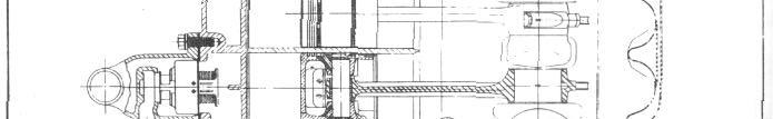
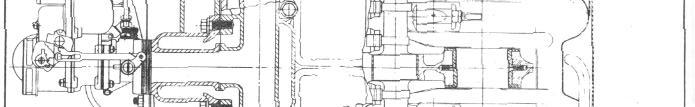
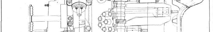
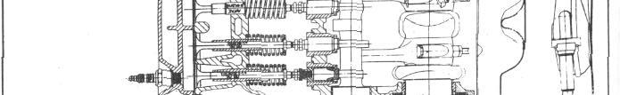
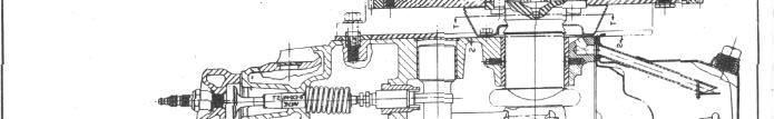
78 3-36 ENGINE FIGURE 41
79 ENGINE Replace coolant and start engine. 19. Adjust tappets (engine hot), Intake -.008; Exhaust Replace tappet covers and breather pipe. NOTE: Tighten breather pipe attaching screw to 2-3 ft. lbs. 21. Replace fender side dust shield and rear inspection shield. (Tie cord of boot to front suspension). FIGURE Install guide clamps, flat washers, lock-washers, and screws. 7. Install valve springs and retainers. NOTE: Installation of valve springs on the 8 cylinder will be facilitated by the use of J-587-A Valve Spring Inserter. 8. Install valves in sequence removed, compress springs, and Install valve keepers. (Valves should be checked for warpage and cracks and replaced as necessary). 9. Install oil pump and connecting lines. 10. Use new gasket, Install cylinder head (Tighten to lbs.). 11. Install carburetor and accelerator linkage. 12. Install radiator; connect hoses (Use Hudson Perfect Seal at all connections). 13.Continuewith balance of cylinder head Installing operations as outlined in "Cylinder Head Installing". 14. Check timing and Install distributor and cap. 15. Install coil and coil bracket. 16. Install fuel pump and connect oil lines. 17. Install complete grille and baffles assembly and front bumper assembly by reversing procedure of removal. 22. Install wheel and lower car. 23. Connect hood prop to hood and align hood. Removal: CAMSHAFT (6 Cylinder) Perform operations under "8 cylinder Camshaft Removal" items 1 to 9 and 12 to 16 inclusive. Valve springs can be removed on the 6 cylinder engines by compressing the springs with a KMO-484 valve lifter and a suitable hook-type tool. NOTE: Tappets should be raised and secured by the use of spring type wood clothes pins or some other practical means, sufficiently to allow removal of the camshaft. Installation: To Install, reverse procedure of removal. (Cyl. Nos. 1 8: 6 TDC. No. 6 firing position) NOTE: Timing chain and sprockets should be Installed with #1 Piston on top dead center with marks on sprockets 14 pitches apart, Figure 44. Timing chain is not adjustable. Also see "Valve Timing".

80 3-38 ENGINE NOTE: To facilitate Installation of two piece valve keepers, use Valve Keeper Installer J-1953, Figure 43. NOTE: Tappet guides must be accurately aligned with cams on camshaft. Position of guides is controlled by the guide clamps; the inner sides of which should be in full contact with matching flat surfaces on front face of each pair of tappet guides within.0015", Figure 42. One method of obtaining alignment is to tighten clamp nuts just less than snugly, then bump outer face of clamps sharply inward using a wide piece of fiber or brass interposed between the hammer and the clamps. This will tend to jar the tappet guides into parallelism with clamps. When clamps are tightened, it should not be possible to insert a.002" feeler blade at any point between inner edge of clamps and mating face of tappet guides. Tappets and Guides (6 Cylinder) FIGURE 43 NOTE: Refer to "Oil Pump Installation" when Installing the oil pump assembly. Tappets and Guides (8 Cylinder) VALVE SYSTEM The tappets and guides can be removed without removing the cylinder head. However, it is recommended that the head be removed when two or more tappets are to be replaced. Removal: 1. Remove cylinder head. 2. Remove R.H. front wheel and fender side dust shield. 3. Remove valve covers and breather pipe. 4. Use valve lifter and remove valve keepers, valves, and springs. 5. Remove tappet guide clamp bolts, washers, clamps and remove tappet and guide assemblies. To Install, reverse the order of removal. Observe the following points during reinstallation: To remove valve tappets on the 6 cylinder engine, it is necessary to remove the oil pan and camshaft. Perform the operations under "Camshaft and Oil Pan Removal - 6 Cylinder". Tappets for the 6 cylinder engines are furnished in standard,.002",.004" and.010" oversizes. Valve Tappet Adjustment (6 & 8 Cylinder) 1. Remove R. H. Front Wheel. 2. Remove fender side shield with side shield extension. 3. Remove valve covers and breather pipe. Adjust tappets as follows: 6 Cylinder 8 Cylinder Intake -.010" hot Intake -.008" hot Exhaust -.012" hot Exhaust -.010" hot VALVES AND SEATS: The valves seat directly in the cylinder block. (No valve inserts are used.) To remove the valves proceed as follows: 1. Drain cooling system. 2. Remove cylinder head. See "Cylinder Head Removal", Pages. 12 and 13.

81 FIGURE 44 ENGINE 3-39
82 3-40 ENGINE 3. Raise car and remove right front wheel and fender shield with extension. 4. Remove both valve covers and breather pipe. 5. Using KMO-484 Valve Spring Lifter compress the valve springs and remove spring keepers and retainers. too wide in the cleaning up process, use a cutter with the proper size pilot to obtain proper valve seat width. When reducing the seat at cylinder head face use a 15 cutter and a cutter at port end. NOTE: Place corks or wood plugs in valve chamber oil return holes to prevent valve locks from dropping through these holes into the oil pan. 6. Remove valves from the engine and place them in a valve rack to protect them from any damage and to insure that the valves are returned to the same seats from which they are removed. 7. Check all valves for warpage and burning, replace any excessively burnt or warped valves. 8. Valves should be refaced on an accredited refacing machine. NOTE: The following chart used in conjunction with the letters and dimensional lines in Figure 45, should be used as a guide when performing any valve work. 6 cyl. A- 45 B " C-.1135" D-.0495" E-.083" F-.016" G-.054" H- 1-11/16" INTAKE 8 cyl. 45º 1.500".1135".036".0765".005".0575" 1-3/8" 6 cyl. 45º 1.561".1525".0496".103".008".075" 1-3/8" EXHAUST 8 cyl. 45º 1.375".1295".036".0935".0045".078" 1-7/32" NOTE: Seat diameter of valve head must be concentric with valve stem within.002" total indicator reading. Valve stem end should be ground flat and square with axis within.002" total indicator reading. A valve head face that is not concentric with the part of the stem that operates in the guide will contact the valve seat on only a small part of the total circumference. It will slap, rattle, leak compression and affect valve timing. Valve seats in the cylinder block should be cut with a suitable valve seat cutter. The seats should be cut only enough to remove pits and surface glaze. If seats are made FIGURE 45 A properly refaced valve will contact the valve seat throughout its entire circumference e and the valve stem will "float" in the guide, free from valve stem friction. NOTE: The best valve grinding and aligning job will go for naught if care is not used when tightening the cylinder head. Always use a torque wrench and tighten the cap screws or stud nuts in the sequence recommended to the following torque specifications foot lbs. for both aluminum and cast iron heads 6 cylinder engines, foot pounds for all 8 cylinder engines. VALVE GUIDES: Before reconditioning a valve seat it is important that the valve guides be checked for wear. Valve guides that are worn.003" more than the clearances recommended in the following chart should be replaced. Valve Stem Valve Guide Valve Stem Valve Guide 6 Cylinder Exhaust Cylinder Exhaust Intake Intake
83 ENGINE 3-41 Valve guides can be removed upward through the valve seat opening with a suitable puller. Valve guides can be properly Installed with the J-883-A Valve Guide Installer. The Installer consists of the driver handle, stop collar, and two pilots calibrated to insure that the guides are driven to the proper depth. On 8 cylinder engines the top of the valve guide should be 15/16" below the top face of the block for both intake and exhaust. See Figure 46. For 6 cylinder engines use the Valve Guide Installer Handle part of J-883-A, the J Pilot Block, J and J Valve Guide Installer Pilots, Figure 47, page 3-41 to Install the valve guides. The Installer pilots are fitted with collars to control the height of the valve guides when Installing the exhaust guide should be 1-3/32" and the intake guide 1-7/16" from the top of the guide to the top face of the block, Figure 48. FIGURE 48 FIGURE 47 To remove the varnish and carbon deposits found in valve guide bores use KMO-122 METAL BRUSH for cleaning th.3. main bore of valve guides. To facilitate removal of stubborn varnish deposits, use lac-thinner and the KMO- 122 Metal Brush. NOTE: Always place clean rags below the valve guides to absorb any surplus draining of the thinner. CHECKING VALVE SPRINGS Whenever valve springs are removed, check spring pressures before Installing. 6 Cylinder 77 lbs. at 2-3/16" 8 Cylinder 40 lbs. at 2" FIGURE 47 Use KMO-607 Spring Tester.

84 3-42 ENGINE 6 Cylinder VALVE TIMING Inlet open 26.7 BTC Inlet closes 91.9 ABC Exhaust opens 67 BBC Exhaust closes 40.3 ATC 8 Cylinder Inlet opens 10-40' BTC Inlet closes 60-0' ABC Exhaust opens 50 BBC Exhaust closes 18-44' ATC VALVE TIMING CHECK 6 and 8 Cylinder To determine if valve timing is correct without dismantling the engine, the following procedure may be used: 1. Remove the front tappet cover and adjust the tappet clearance of #1 intake valve to.010 with engine hot or.012 with engine cold. 2. Insert a.002" feeler gauge in #1 intake tappet and rotate engine in direction of rotation until exhaust valve begins to close. Continue to rotate engine very slowly until a light drag is felt on the feeler gauge. 3. At this point, inspect the timing marks on the flywheel through the opening in the rear engine support plate. (No. 6 ready to fire.) The engine is correctly timed when the first of the five timing marks is approximately 5/8" above the index of the timing hole shown as "A", Figure 49. When checking eight-cylinder valve timing, dimension "A" should be 9/16". 4. Reset No. 1 intake valve to recommended clearance of.010" hot or.012" cold and reinstall tappet cover. VALVE MAINTENANCE If valve tappets, with proper clearance, a re noisy the following points should be checked: 1. Tappets loose in their guides. 2. Tappets not properly rotating causing uneven wear on tappet faces. 3. Weak valve springs. 4. Valve sticking in valve guides. 5. Valves loose in valve guides. 6. Valve springs cocked or not seating properly. 7. Warped valve. 8. Valve seat and guide not in alignment. CYLINDER BORING OR HONING Careful washing and careful protection before reconditioning the cylinder bores will save a great deal of expense later. Crankshaft bearings, camshaft bearings, connecting rod bearing surfaces on the crankshaft, crankcase walls, in fact the entire part of the engine below the bottom of the cylinder bores must be protected from any particles of grit, chips, etc. After reboring the cylinders or honing them, it is necessary that they be thoroughly washed. FIGURE 49 All traces of abrasive material will have to be removed or extremely rapid wear of the new parts will result.
85 SECTION 4 FUEL SYSTEM & EXHAUST CARBURETOR WA-1-749S (1950 to '54, 232 en.) ENGINE 4-1 SPECIFICATIONS: Make Type Main Venturi Primary Venturi Flange Size Secondary Venturi Float Level Idle Adjustment Pump Plunger Travel from Closed to Wide Open Throttle Low Speed Jet Tube Vents: Gasoline Intake:. Gas Line Connection: Idle Port: Idle Port Opening: Idle Screw Seat Main Nozzle: Carter No :. E Carter Single Throat Down Draft 1-3/8" I.D. 11/32" I.D. 1-1/2" 11/16" I.D. 1/2" 1/2 to 1-1/2 turns open 16/64" Jet size No. 65 (.035") drill. By-pass, size 1.6 M.M. No. 63 drill. Economizer,.0515" " diameter. Idle bleed, No. 52 (.0635") drill. Outside Only No. 10 drill. Square vertical nee - dle, Size No. 46 (.081") drill hole in needle seat. 5/16" weatherhead nipple. Length.190", width.040".136" to 140" above valve with valve closed. No. 46 drill. Slip nozzle, flush type, (angle tip) seats in primary venturi at 45 angle. Discharge jet size.110" dia. Inner nozzle (seats in slip nozzle) I. D. No. 31 drill (.120"). Metering Rod Jet Metering Rod Carter No Length of Taper (All) Power Step Standard 1st. Leaner 2nd. Leaner 3rd. Leaner Length of Step Metering Rod Setting: Standard 1st. Leaner 2nd. Leaner 3rd. Leaner.1015" diameter (Vacumeter Type) Economy Step Use Gauge J-1265 Carter T Accelerator Pump: Pressure type with adjustable stroke. Discharge jet, size No. 72 drill. Intake ball check size No. 60 drill. Discharge ball check No. 32 drill. Relief passage (to outside) No. 42 drill to to to to Diameter " Pump Adjustment - 16/64" plunger travel, (full throttle position) short stroke. Choke: Climatic control, set at index. Butterfly type, offset valve. Choke heat suction hole, in body size No. 30 drill. Anti-Percolator Valve: Saxophone Key Vacuum Spark Port:.054" -.057" diameter. Bottom of port.020" above valve.
86 4-2 ENGINE SECTION 4 FUEL SYSTEM & EXHAUST SPECIFICATIONS: CARBURETOR WA S Metering Rod Jet (1952 to 53, 262 dual).1015" Diameter Make Type Main Venturi Primary Venturi Secondary Venturi Flange Size Float Level Idle Adjustment Pump Plunger Travel from Closed to Wide Open Throttle Low Speed Jet Tube Vent Gasoline Intake Idle Port Idle Port Opening Idle Screw Seat Main Nozzle: Carter Single Throat Down Draft 1-3/8" I.D. 11/32" I.D. 11/16" I.D. 1-1/2" 1/2" 1-1/4" to 2-1/4" turns open 16/64 Jet size No. 65 (.035") drill. By-pass, size 1.6 MM (.063") drill. Economizer, in body,.0545" " diameter. Idle bleed, size No. 52 (.0635") drill. Outside only No. 10 drill. Square vertical pushpull needle, size No. 46 (.081") drill hole in needle seat. Length.190", Width.040". 178" t o.182" above valve with valve tightly closed. No. 46 drill. Slip nozzle, flush type, (angle tip) seats in primary venturi at 45 angle. Discharge jet size.110" diameter. Inner nozzle (seats in slip nozzle). Inside diameter No. 31 (.120") drill. Metering Rod Length Economy Step Middle Step Tapers to Power Step Metering Rod Setting: Use Gauge J-1265 Carter T Accelerating Pump: Anti-Percolator Valve: (Vacumeter Type) 3-9/64".076" Diameter.063" Diameter.056" Diameter Pressure type with adjustable stroke. Discharge jet, size No. 74 (.0225") drill. Intake ball check size No. 60 (.040") drill. Discharge ball check size No. 32 (.116") drill. Relief passage (to outside) No. 42 (.0935") drill. Pump Adjustment - 16/64" plunger travel. Medium stroke. Use gauge No. T Choke: Climatic control, set 1 point lean. Butterfly type, offset valve. Choke heat suction hole in body, size No. 40 (.098") drill. Saxophone Key Vacuum Spark Port:.054" -.057" diameter. Bottom of port.049" above top edge of valve.
87 SECTION 4 FUEL SYSTEM & EXHAUST ENGINE 4-3 SPECIFICATIONS: Make Type Main Venturi Primary Venturi Secondary Venturi Flange Size Float Level Idle Adjustment Pump Plunger Travel from Closed to Wide Open Throttle CARBURETOR WA S (1952 to '53, 262 dual) Carter Single Throat Down Draft 1-3/8" I.D. 11/16" I.D 11/32" I.D. 1-3/8" 1/2" 3/4 to 1-3/4 turns 16/64" Metering Rod Jet Metering rod Length Economy Step Middle Step Tapers to Power Step Metering Rod Setting:.1015" Diameter (Vacumeter Type) 3-9/64".075" Diameter.059" Diameter.055" Diameter Low Speed Jet Tube Vent Gasoline Intake Idle Port Idle Port Opening Idle Screw Seat Main Nozzle Jet size No. 65 (.035") drill. By-pass size No. 53 (.0595") drill. Economizer, in body,.0545" " diameter. Idle bleed, size No. 53 (.0595") drill. Outside only No. 10 drill. Square vertical push-pull needle, size No. 46 (.081") drill hole in needle seat. Length.165", width.030". 120" t o.124" above valve with valve tightly closed. No. 46 drill. Slip nozzle, flush type, (angle tip) seats in primary venturi at 45 angle. Discharge j e t size.110" diameter. Inner nozzle (seats in slip nozzle). Inside diameter No. 31 (.120") drill. Use Gauge J-1265 Carter T Accelerating Pump: Pressure type spring operated lever with adjustable stroke. Discharge jet, size No. 74 (.0225") drill. Intake ball check size No. 60 (.040") drill. Discharge ball check size No.32 (.116") drill. Relief passage (to outside) No. 42 (.0935") drill. Pump Adjustment - 16/64" plunger travel. Medium Stroke. Use gauge No. T Choke: Climatic control, set 1 point lean. Butterfly type, offset valve. Choke heat suction hole in body, size No. 40 (.098") drill. Anti-Percolator Valve: Saxophone Key Vacuum Spark Port:.051" -.054" diameter. Bottom of port.040" above top edge of valve.
 during the warmup period.")

88 4-4 FUEL SYSTEM & EXHAUST against an adjusting screw when the choke is closed. The screw is adjusted to hold the throttle open sufficiently to provide necessary engine speed (fast idle) during the warmup period. As the choke valve opens, the fast idle cam moves away from the screw allowing the engine to run at normal idle speed. An unloader is provided in the choke linkage to open the choke valve when the accelerator pedal is fully depressed. This allows the engine to clear itself of excess fuel if the engine is flooded during the starting period. ANTI-PERCOLATOR VALVE: When the car stands in extremely hot weather or after a hard run, fuel in the carburetor bowl may vaporize and set up pressure in the bowl. To prevent this pressure forcing the fuel out the high speed nozzle (percolating), an anti-percolator device vents the carburetor bowl to the atmosphere when the throttle is closed, relieving the pressure in the bowl. FIGURE 1 CLIMATIC CONTROL (CHOKE): All model WA-1 Carburetors are equipped with Carter Climatic Control, Figure 1, which serves as an automatic choke. The Climatic Control closes the choke valve when the engine is cold. The Climatic Control is connected to the exhaust manifold by a tube (I) which allows exhaust gases to enter through the opening into the control housing and warm the thermostatic spring (C) and decreases the spring tension. A vacuum piston (D) is connected to the choke valve and operates from the vacuum of the intake manifold. The pull of the piston against the thermostatic spring opens the choke valve (H) as the engine becomes warm. To prevent the thermostatic spring (C) from closing the choke valve if the throttle is opened on a cold engine, a lockout is provided in the choke linkage to hold the choke open on all wide open throttle operations. A cam on the choke valve shaft is brought FIGURE 2 COPYRIGHT 1950 BY CARTER CARBURETOR CORPORATION ALL RIGHTS RESERVED

89 FUEL SYSTEM & EXHAUST 4-5 An anti-percolator valve that opens too early will allow excess air to be drawn into the high speed circuit. If the valve fails to open, it will cause difficult starting when the engine is hot. The WA-1-749S carburetor has one saxophone key type anti-percolator valve, Figure 2. ACCELERATING PUMP: The WA-1 carburetor, Figure 3, incorporates a throttle operated accelerating pump which discharges additional fuel into the carburetor throat when the throttle is opened. The discharge is prolonged by the pressure of the pump and the restriction of the pump jet. This discharge allows time for the high speed circuit to furnish necessary fuel. valve is opened and the fast idle cam moves away from the adjusting screw, allowing the throttle to close and engine to idle at normal speed. METERING RODS: The amount of fuel admitted to the carburetor throat through the high speed circuit is controlled by a stepped and tapered metering rod. Figure.3.2 Opening the throttle raises the metering rod allowing more fuel to pass through the jet. At top speed the smallest section of the metering rod is in the jet. Under heavy load at part throttle and for acceleration at part throttle, a richer than normal air-fuel ratio is required. To provide this richer mixture, regardless of throttle position, the metering rod is connected to a vacuum piston. Under normal operating conditions the vacuum piston holds the metering rod down against the throttle link. When the engine vacuum drops, a spring under the vacuum piston raises the piston and metering rod, allowing more fuel to flow through the jet. As soon as the engine vacuum rises, the need for rich mixture passes and the vacuum piston returns the metering rod to normal position for mechanical operation through the throttle linkage. PUMP TRAVEL: WA-1 CARBURETOR ADJUSTMENTS FAST IDLE: FIGURE 3 Provision is made on this carburetor for a faster idle speed during the warm-up period. This is accomplished by a cam on the choke valve shaft which holds the throttle open slightly when the choke valve is closed. As soon as the engine becomes warm, the choke 1. Remove the carburetor dust cover. 2. Back out throttle adjusting screw to seat throttle valve. 3. Pump connector link should be in the lower hole (short stroke), Figure Pump travel should be 16/64". Use Carter Universal Pump Stroke Gauge T if available. 5. Adjust pump travel by bending throttle connecting link at lower angle, Figure 3. COPYRIGHT 1950 BY CARTER CARBURETOR CORPORATION ALL RIGHTS RESERVED
. Hold gauge vertical and be sure gauge is seated in metering rod jet, Figure 4. 5.")
. 7. Remove gauge and Install metering rod and disk. 8. Reconnect metering rod spring.")
90 4-6 FUEL SYSTEM & EXHAUST FIGURE 5 FIGURE 4 METERING ROD SETTING: 1. Remove air cleaner and dust cover. 2. Remove hairpin clip and disconnect spring from metering rod. 3. Remove metering rod and disk. 4. Insert metering rod gauge, (Carter No. T ). Hold gauge vertical and be sure gauge is seated in metering rod jet, Figure Press down on vacuum piston link directly over piston until it contacts the pump arm. Clearance between metering rod pin and shoulder of gauge should be less than.005" with throttle valve seated. Gauge must not drag on pin. 6. Adjust by bending lip on piston link at (A). 7. Remove gauge and Install metering rod and disk. 8. Reconnect metering rod spring. ANTI-PERCOLATOR ADJUSTMENT: NOTE: Carburetor must be removed from engine. 1. Crack throttle valve.020" b y placing gauge J-1633 (Carburetor No. T ), between throttle valve and bore of carburetor on side opposite the idle port, Figure Clearance between percolator rocker arm lip and pump arm should be.005" to.015" at (B) Figures 4 and 6. FIGURE 6 3. Adjust by bending the rocker arm at (A) Figure 4, using Bending Tool H-1389 to obtain this clearance. COPYRIGHT 1950 BY CARTER CARBURETOR CORPORATION ALL RIGHTS RESERVED
91 FUEL SYSTEM & EXHAUST 4-7 UNLOADER ADJUSTMENT: 1. Remove carburetor air cleaner. 2. Open throttle wide open and check between lower edge of choke valve and air horn (A), Figure 7. Clearance should be 7/16". is against but not on set screw (B), Figure Clearance between lower edge of choke valve and air horn should be 5/8", (A), Figure Adjust by bending fast idle link at offset portion. 3. Adjust by bending cam (B) on throttle lever using Bending Tool J IDLE ADJUSTMENT: FIGURE 8 FIGURE 7 FAST IDLE ADJUSTMENT: 1. Remove Carburetor air cleaner. 2. With fast idle cam in normal idle position, tighten throttle lever adjusting screw (A), Figure 8, until it just seats against the cam. 3. Hold throttle lever closed and pull cam back until low step 1. Start engine and allow engine to warm up. 2. See that choke valve is wide open. 3. Set idle adjustment screw to obtain smooth idle at 540 to 560 RPM on cars equipped with standard transmission. ( RPM for cars equipped with Hydra-Matic transmission.) 4. Normal setting is 1/2 to 1-1/2 turns open on WA1-749S Carburetors - 1-1/4 to 2-1/4 turns open on WA1-968S Carburetors. 3/4 to 1-3/4 turns open on WA1-990S Carburetors. REMOVAL: WA-1 CARBURETOR 1. Remove air cleaner. Loosen clamp at air horn. 2. Disconnect throttle linkage at carburetor. 3. Disconnect, gas line from carburetor to fuel pump. COPYRIGHT 1950 BY CARTER CARBURETOR CORPORATION ALL RIGHTS RESERVED


92 4-8 FUEL SYSTEM & EXHAUST 4. Disconnect vacuum line from carburetor to distributor. 5. Disconnect heat riser line from exhaust manifold to carburetor. 6. Remove nuts and lock-washers from the carburetor mounting studs and remove carburetor assembly. DISASSEMBLY: 1. Remove fast idle cam and pin assembly, Figure 9 FIGURE Check throttle connector rod for wear at both ends and at hole in pump arm. Remove bowl cover gasket and pump spring FIGURE 9 2. Remove air horn and climatic control assembly, Figure 10, and lift off air horn gasket. FIGURE Remove the metering rod jet and gasket assembly, Figure 12. FIGURE Disconnect throttle connector rod; then remove bowl cover with all parts attached. Remove throttle shaft arm assembly. FIGURE 13 COPYRIGHT 1950 BY CARTER CARBURETOR CORPORATION ALL RIGHTS RESERVED
93 FUEL SYSTEM & EXHAUST Remove the low speed jet assembly, Figure Remove nozzle passage plug, nozzle retainer plug and nozzle, Figure 16. (Be sure to remove small nozzle gasket from casting.) FIGURE Remove the pump jet plug and gasket assembly and pump jet, Figure 14. FIGURE Remove the pump strainer, and pump intake check ball, Figure 17. FIGURE Remove the pump discharge ball retainer and gasket, and check ball, Figure 15. FIGURE Separate body from flange assembly, Figure 18, and remove body flange gasket. FIGURE 16 FIGURE 19 COPYRIGHT 1950 BY CARTER CARBURETOR CORPORATION ALL RIGHTS RESERVED

94 4-10 FUEL SYSTEM & EXHAUST 12. Remove idle adjustment screw and spring, Figure 19. Check for groove on seating surface. 2. Examine each part and replace any part that shows wear, or does not meet specifications. Use all new gaskets and new screws on throttle and choke valve. FIGURE Remove idle port rivet plug with rivet extractor KMO-481. FIGURE Install strainer and strainer nut and gasket assembly, Figure 22. FIGURE Remove throttle valve screws, valve and throttle shaft and lever assembly, Figure 21. Check shaft for wear or loose lever and throttle rod hole in lever for wear. FIGURE Install needle seat and gasket assembly, Figure 23. Check for wear. If either the needle or seat shows wear, replace both. 15. Remove choke valve screws, choke valve, shaft and piston assembly from air horn. Do not remove the piston housing (attached to the air horn with rivets). 16. Remove all parts from the bowl cover. ASSEMBLY: 1. Clean casting and metal parts thoroughly with a good commercial carburetor cleaning compound. FIGURE 24 COPYRIGHT 1950 BY CARTER CARBURETOR CORPORATION ALL RIGHTS RESERVED


95 FUEL SYSTEM & EXHAUST Install the needle, float and lever assembly, and float lever pin. Check float for dent s and wear on hp, and float pin for wear. Check bowl cover for wear in counter-shaft hole. Set float level to 1/2" by bending lip that contacts the needle. Do not bend float, Figure 24. Measure distance from projection on bowl cover to soldered seam of float, as shown. 6. Install throttle shaft and lever assembly and throttle valve. Small "c" in circle should be toward idle port facing manifold side of flange, Figure 25. Center the valve by tapping valve lightly before tightening screws. Peen ends of screw threads to keep screws from loosening. 8. Install idle adjustment screw and spring, Figure 27. Back out from seated position 1/2 to 1-1/2 turns, Models WA1-749S, 1-1/4 to 2-1/4 turns for Models WA1-968S and 3/4 to 1-3/4 turns for Models WA1-990S. (Make final adjustment after Installation.) FIGURE Assemble body and body flange assembly, Figure 28. Install screws and lock-washers. Pull screws down evenly. FIGURE 25 NOTE: Back out throttle lever adjusting screw before Installing shaft assembly. FIGURE Install low speed jet assembly, Figure 29. (Be sure jet seats firmly in casting.) FIGURE Install idle port rivet plug, Figure 26. FIGURE 30 FIGURE Install pump jet and pump jet passage plug and gasket assembly, Figure 30. (Be sure jet is clear of all restrictions and seats properly.) COPYRIGHT 1950 BY CARTER CARBURETOR CORPORATION ALL RIGHTS RESERVED

96 4-12 FUEL SYSTEM & EXHAUST FIGURE 31 FIGURE Install pump check ball and pump discharge ball retainer and gasket, Figure 31. If jet is worn, replace both metering rod and jet. FIGURE Install pump intake check ball and pump strainer, Figure 32. FIGURE Install the bowl cover assembly, Figure 35. Pull the screws down evenly. Install idle passage plug and gasket assembly (center of bowl cover). FIGURE Install pump spring and pump plunger and rod assembly, Figure 33. Examine leather of plunger for damage. If leather is not in good condition, replace entire plunger assembly. 15. Install metering rod jet and gasket assembly, Figure 34. Examine for wear. FIGURE Install the anti-percolator cap and rocker arm assembly and spring, Figure 36. (Make certain that leather is in good condition and that pin is not worn.) COPYRIGHT 1950 BY CARTER CARBURETOR CORPORATION ALL RIGHTS RESERVED


97 FUEL SYSTEM & EXHAUST Install pump arm and countershaft assembly, Figure 37. Install connector link on pump shaft in lower hole in pump arm. FIGURE With throttle connector rod in place, adjust pump stroke. Use Carter universal pump travel gauge T or machinist's scale, Figure 39, and set pump travel to 16/64". Adjust by bending throttle connector rod at lower angle. 21. Adjust metering rod after pump adjustment is made. (See Figure 4). Insert metering rod gauge in place of metering rod, seating tapered end in jet. With throttle valve seated, press down lightly on piston link directly over piston. There should be less than.005" clearance between metering rod pin and should e r of notch in gauge. Gauge must not drag on pin. Adjustment can be made by bending lip on piston link so that it contacts hump on pump arm. Remove gauge, Install rod and disc, and connect spring. FIGURE Install the throttle shaft arm and screw assembly and throttle connector rod. Figure 38. Check throttle shaft arm for wear. FIGURE Adjust anti-percolator, Figure 40, as outlined on Page 4-6, Figures 5 and 6. FIGURE 41 FIGURE Install nozzle, nozzle retainer plug and nozzle passage plug and gasket assembly, Figure 41. COPYRIGHT 1950 BY CARTER CARBURETOR CORPORATION ALL RIGHTS RESERVED


98 4-14 FUEL SYSTEM & EXHAUST with indicator marks at bottom and rotate counter clockwise to center graduation. FIGURE Install air horn and piston housing assembly, Figure 42. Install screws and lock-washers. Tighten screws evenly. FIGURE 45 FIGURE 43 FIGURE With choke lever, screw and link assembly in place, Install choke shaft and piston assembly, Figure 43. Check for loose lever on shaft. 28. Hold choke valve wide open, then tighten the choke lever screw as shown in Figure 46. Be sure that linkage does not bind in any position. Fast idle, unloader and lock out adjustments should be made as specified under "Carburetor Adjustments. FIGURE Install choke valve, Figure 44. Center choke valve on shaft and in bore by tapping lightly. Hold in place with finger while tightening screws. Peen ends of screw threads to keep screws from loosening. 27. Install the piston housing and thermostatic coil assembly, Figure 45. Install coil housing assembly FIGURE Install fast idle cam and pin assembly, Figure 47. COPYRIGHT 1950 BY CARTER CARBURETOR CORPORATION ALL RIGHTS RESERVED
99 FUEL SYSTEM & EXHAUST 4-15 CARBURETOR WGD SPECIFICATIONS: Make Model 6 Cyl 8 Cyl Type Main Venturi Primary Venturi Secondary Venturi Float Level Idle Adjustment Low. Speed Jet Tube Vents Gasoline Intake Carter WGD 776-S WGD 773-S Dual Downdraft 1-1/4" 1-3/16" I.D. 11/32" I.D. 1/32" I.D. Distance from Lowest part of float to bowl cover when needle is seated to be 3/16". (Use Gauge J-818-3) 1/2 to 1-1/2 turns open, 6 cylinder. 1 to 1-1/2 turns open, 8 cylinder. Jet No. 66 D rill, (.033"). By-pass No. 55 drill, (.052"). Economizer 1.15 M.M..045" drill. Idle bleed No. 56 (.0465") drill. Outside only No. 10 drill (.1935"). Square vertical (push-pull) needle seat size No. 42 (.0935") drill. Nozzle Anti-percolating well; jet size No. 66 drill Metering Rod Jet Metering Rod Accelerating Pump. In primary venturi, round end type. Inside diameter No. 30 drill. Nozzle is Installed permanently. DO NOT REMOVE..089" diameter (Vacumeter Type) Economy step.068" diameter. Middle step tapers to.063" diameter. Power step,.048" diameter. Length 2-59/64". Economy step,.068" diameter. Middle step tapers to.063" diameter. Power step,.044" diameter. Length 2-59/64". Pressure type delayed action plunger. Discharge jet (twin) No. 74 drill. Intake ball check, No.40 (.098") drill. Discharge (Needle seat) No. 50 drill. Pump jet air bleed passage to outside 1/8" drill. Idle Ports Upper port, slot type length.200", width.030". Pump Adjustment 5/16" plunger travel (full throttle position). Idle Port Opening Lower Port (For Idle Adjustment Screw) 157" t o.163" above upper edge of valve with valve closed tight. Size.0615" t o.0655" diameter. Choke Climatic Control Butter-fly type-offset valve. Set on index for (WGD-773-S). Set two points lean for (WGD-776-S). Choke heat suction hole in body No. 36 drill.
 FLOAT ADJUSTMENT: Holding the bowl cover inverted and gasket removed and with the float needle (A) Figure 48, seated, there should be 3/16\" clearance between the top of")

100 4-16 FUEL SYSTEM & EXHAUST Vacuum Spark Port:.039" to.041" diameter. Top of port..010" to.020" above valve. CARBURETOR ADJUSTMENTS (WGD) FLOAT ADJUSTMENT: Holding the bowl cover inverted and gasket removed and with the float needle (A) Figure 48, seated, there should be 3/16" clearance between the top of float (B) and bowl cover (C). (Use gauge J Carter No. T ) Measurement to be taken at lowest pointof float, (approximately at center of float). FIGURE 49 METERING ROD ADJUSTMENT: NOTE: The metering rods must be adjusted after the pump travel adjustment or when leaner than standard rods are Installed. (No metering rod gauges are necessary for this adjustment). 1. With the throttle lever set screw backed out as in "Pump Adjustment", press down on vacumeter link (1) Figure 50, until metering rods bottom. FIGURE 48 PUMP TRAVEL ADJUSTMENT: 1. Back out throttle lever set screw until throttle valves (G) Figure 49, seat in bores (F) of carburetor and leave screw backed out until carburetor is Installed on engine. 2. With the pump connector link in the outer hole (D) in pump arm (long stroke) the pump plunger should travel 5/16" from closed throttle to wide open throttle position. 3. Measurement can be made with suitable depth gauge. 4. If adjustment is necessary, bend the throttle connector rod at the upper angle (C) FIGURE 50
 towards connector link side and carefully tighten the metering rod arm set screw (J). 2.")
 Figure 51, and hold choke valve closed by holding down on choke lever (L). FIGURE 52 3.")
101 FUEL SYSTEM & EXHAUST With metering rods bottoming, revolve metering arm (K) until lip (H) (See insert) contacts vacumeter link (I). Hold arm (K) towards connector link side and carefully tighten the metering rod arm set screw (J). 2. Check clearance between upper edge of choke valve and inner wall of air horn; this should be 1/8" (use Tool J-818-5), Figure 52. FAST IDLE ADJUSTMENT: 1. With the thermostatic coil housing, gasket an d baffle plate removed, open throttle valve (F) Figure 51, and hold choke valve closed by holding down on choke lever (L). FIGURE If adjustment is necessary, bend arm (N) on choke trip lever. Use Tool KMO-478 (T ). FIGURE Then close throttle. There should now be.026" clearance (use gauge KMO-658, T ) between the throttle valve and bore of carburetor (side opposite idle port). Adjust by bending the choke connector rod at lower angle (M). UNLOADER ADJUSTMENT: This adjustment must be made after making the fast idle adjustment. 1. Hold the throttle valve wide open and close the choke valve as far as possible without forcing. IDLE ADJUSTMENT: 1. With carburetor Installed on engine, start engine and allow engine to warm up. 2. See that choke valve is wide open. 3. Set idle adjustment screws to obtain smooth idle at 540 to 560 RPM. (If car is equipped with the Hydra-Matic Transmission, set idle at 490 to 510 RPM. 4. On eight cylinder engines the normal screw setting is 1 to 1-1/2 turns open on six cylinder engines 1/2 t o 1-1/2 turns open. REMOVAL: WGD CARBURETOR 1. Remove the air cleaner. Loosen clamp at carburetor air horn. 2. Disconnect throttle linkage at carburetor. 3. Disconnect fuel line from carburetor to fuel pump COPYRIGHT 1950 BY CARTER CARBURETOR CORPORATION ALL RIGHTS RESERVED


102 4-18 FUEL SYSTEM & EXHAUST fuel pump (at carburetor). 4. Disconnect vacuum line from carburetor to distributor. 5. Disconnect heat riser tube from exhaust manifold to carburetor. 6. Remove nuts and lock washers from the carburetor mounting studs and remove the carburetor assembly. 3. Remove bowl cover with all parts attached, Figure 55. DISASSEMBLY: 1. Remove the dust cover screws, cover and gasket, Figure 53. FIGURE Remove the body flange screws and remove the body flange assembly and gasket, Figure 56. FIGURE Remove the retainer clips and remove the throttle connector rod and choke connector rod, Figure 54. NOTE: Check the throttle and choke connector rods at both ends for wear FIGURE Remove all parts from bowl cover, Figure 57. FIGURE 54 FIGURE 57 COPYRIGHT 1950 BY CARTER CARBURETOR CORPORATION ALL RIGHTS RESERVED


103 FUEL SYSTEM & EXHAUST Remove a 11 parts from the carburetor body, except nozzles and other pressed in parts, Figure 58. carbon from bores of flange. Replace all worn or damaged parts and all gaskets. After cleaning carburetor parts, group as follows: 1. Group all parts controlling gasoline level, Figure 60. FIGURE 60 FIGURE Group all parts controlling the idle operation, Figure Remove all parts from the body flange assembly, Figure 59. FIGURE Group all parts controlling the high speed operation, Figure 62. FIGURE 59 NOTE: Wash all parts in a good carburetor cleaning solution, except the thermostatic coil and housing assembly and the pump plunger. CAUTION: DO NOT SOAK THE BOWL COVER ASSEMBLY FOR MORE THAN ONE-HALF HOUR. NOTE: Carefully note slots in choke piston cylinder. If they are carbonized, remove the welsh plug by piercing center with a small pointed instrument and pry outward. Be careful not to damage the casting. Blow out all passages with compressed air and scrape FIGURE 62 COPYRIGHT 1950 BY CARTER CARBURETOR CORPORATION ALL RIGHTS RESERVED
 2. Install the throttle valves. Small \"c\" at (A), Figure 66, in circle should be toward idle port at (B) (when viewing casting from manifold side).")
104 4-20 FUEL SYSTEM & EXHAUST 4. Group all parts controlling pump operation, Figure Install all parts controlling IDLE OPERATION. Install throttle shaft and lever assembly, Figure 65. (Back out throttle lever adjusting screw.) 2. Install the throttle valves. Small "c" at (A), Figure 66, in circle should be toward idle port at (B) (when viewing casting from manifold side). Center throttle valves by tapping lightly and holding in place with fingers before tightening screws. Always use new screws. Peen threaded end of screws to keep screws from loosening. FIGURE Group all parts controlling choke operation, Figure 64. NOTE: If welsh plug has been removed from the choke housing for cleaning, Install a new plug. FIGURE With throttle closed, press shaft from lever side and Install throttle centering washer at "C", Figure 67, prongs of washer extending outward. Press washer tight against carburetor casting. FIGURE 64 FIGURE 67 FIGURE Install idle port rivet plugs (D), Figure 68. Then Install idle adjustment screws and springs. (Adjust to specifications as shown on page 4-17, "Idle Adjustment"). COPYRIGHT 1950 BY CARTER CARBURETOR CORPORATION ALL RIGHTS RESERVED
, Figure 71.")

, Figure 72, gasket (K) and pump jet")

105 FUEL SYSTEM & EXHAUST Install the intake ball check (G), Figure 71. Then Install the retainer ring (H) and the strainer (I). FIGURE Install low speed jet assemblies, Figure 69. (No gaskets are used.) FIGURE Install discharge check needle (J), Figure 72, gasket (K) and pump jet cluster (L) and screw. (Use new gasket.) FIGURE Assemble body casting to flange, Figure 70. (Use new gasket.) FIGURE Install lower pump spring and plunger assembly, Figure 73. FIGURE 70 FIGURE 73 COPYRIGHT 1950 BY CARTER CARBURETOR CORPORATION ALL RIGHTS RESERVED


 FIGURE 74 11.")
, Figure 78, lip on link")
 FIGURE 78 FIGURE 76 15.")
106 4-22 FUEL SYSTEM & EXHAUST 10. Install bowl strainer gauge, nut and gasket assembly as indicated by arrow, Figure 74. Figure 76, then lower needle into seat until float and lever line up with holes and Install float lever pin. (Set float to specifications, Page 4-15 and Install new bowl cover gaskets.) 13. Install metering rod jets, Figure 77. (No gaskets are used.) FIGURE Install needle seat and gasket assembly (M), Figure 75. FIGURE Install vacumeter piston link and metering rod spring at (P), Figure 78, lip on link extending toward air horn. FIGURE Attach the intake needle and pull clip to float lip at (N) FIGURE 78 FIGURE Install vacumeter piston (Q), Figure 79, on link with pin extending away from float. (Install a new bowl gasket.) COPYRIGHT 1950 BY CARTER CARBURETOR CORPORATION ALL RIGHTS RESERVED
107 FUEL SYSTEM & EXHAUST 4-23 FIGURE 79 FIGURE Install vacumeter spring (R), Figure 80, in cylinder and assemble bowl cover on body. (Install bowl cover screws, tightening center screws first.) FIGURE Set pump stroke, Figure 83, (see Page 16, for pump stroke setting). FIGURE Install pump connector link (S), Figure 81 in outer hole of pump arm and Install hair pin clip. Insert the lower end of pump connector link in hole in plunger shaft. Hold arm (R) in place and press shaft through arm. Hold metering rod arm (U) with lip extending through slot in vacumeter piston link and press shaft in place. Tighten pump arm (T) screw and metering rod arm (U) screws. 18. Install the throttle shaft lever, washer and screw at (V), Figure 82. Install throttle connector rod and retainer clips. FIGURE 83 COPYRIGHT 1950 BY CARTER CARBURETOR CORPORATION ALL RIGHTS RESERVED
, Figure 84.")
 of link, tighten metering rod arm set screw.")

108 4-24 FUEL SYSTEM & EXHAUST 20. Install metering rods. Catch the metering rod spring loop with lower end of the, metering rod as rods are inserted (W), Figure 84. Adjust metering rods in the following manner: a. Back out the throttle lever adjusting screw so throttle valves seat. b. Loosen metering rod arm set screw. c. Press down on the vacumeter link until metering rods bottom in body casting. d. With torque on arm touching lip (top of slot) of link, tighten metering rod arm set screw. e. Install dust cover gasket, dust cover and screws. FIGURE Connect the fast idle cam spring to the choke piston lever at (X), Figure 87. FIGURE Install fast idle cam and spring as indicated by arrow, Figure 85. FIGURE Install choke valve using new screws. FIGURE Install choke piston, lever, link and shaft, Figure 86. FIGURE 88 COPYRIGHT 1950 BY CARTER CARBURETOR CORPORATION ALL RIGHTS RESERVED

109 FUEL SYSTEM & EXHAUST 4-25 NOTE: Choke valve to be Installed with the circled "C" visible from the top of the carburetor with valve in closed position as indicated by an arrow, Figure 88. Seat choke valve by tapping lightly; hold in place with fingers before tightening screws. Valve or shaft must not bind in any position. Peen threaded end of screws to prevent screws from loosening. 25. Install the fast idle link, choke connector rod and retainer clip, Figure 89. FIGURE Check the unloader adjustment as follows: With the throttle valves wide open, bend lip (Z), Figure 92, on choke trip lever to get clearance between top edge of choke valve and inner wall of air horn. See Page 4-17, "Covering Unloader Adjustment." FIGURE Install choke trip lever assembly, Figure 90. FIGURE Install choke baffle plate and gasket, Figure 93. FIGURE With the choke valve tightly closed, adjust the fast idle by bending choke connector rod at the lower angle (Y), Figure 91; to give proper clearance between the throttle valve and base of carburetor. See "Fast Idle Adjustment", Page FIGURE 93 COPYRIGHT 1950 BY CARTER CARBURETOR CORPORATION ALL RIGHTS RESERVED

110 4-26 FUEL SYSTEM & EXHAUST 30. Install the thermostatic coil and housing assembly, retainers and screws, Figure 94. Install housing with index marks to bottom and revolve housing in direction of arrow, set index marks to specifications; see "Climatic Control Setting," Page After making proper adjustment, tighten attaching screws. FIGURE Connect vacuum line from distributor to carburetor, (F). FIGURE 94 Installation OF WA-1 OR WGD CARBURETOR NOTE: Place four gaskets on each side of heat deflector, Figure 95. Replace all broken or damaged gaskets and straighten deflector if damaged. FIGURE 97 FIGURE Install carburetor and Install nuts and lock washers on the carburetor mounting studs (E), Figures 96 and Connect gas line from fuel pump to carburetor, (G). 4. Connect heat riser line from exhaust manifold to carburetor (H). 5. Connect throttle linkage to carburetor; Install clamp. 6. Adjust and test carburetor for maximum performance. 7. Install air cleaner. NOTE: Do not tighten air cleaner clamp so tight that carburetor air horn may be distorted. COPYRIGHT 1950 BY CARTER CARBURETOR CORPORATION ALL RIGHTS RESERVED
111 TWIN CARBURETOR Installation INSTRUCTIONS Installation INSTRUCTIONS (6B-7B MODELS) 1. Drain coolant from radiator. 2. Disconnect accelerator rod at bell crank, throttle valve rod from throttle valve lever on transmission (if equipped with Hydra-Matic) also bellcrank and connecting linkage to carburetor. 3. Remove vacuum line from carburetor to distributor and fuel line from fuel pump to carburetor. 4. Remove windshield wiper hose from manifold (or vacuum line from combination pump to manifold if so equipped). FUEL SYSTEM & EXHAUST Disconnect exhaust pipe flange from elbow. 6. Remove weather control hose (Ranco valve to cylinder head) and remove hose nipple from head. 7. Remove weather control outlet pipe, (hose to water pump). 8. Remove 14 nuts and retainers attaching manifolds to block and remove manifolds with carburetor attached. 9. Place the manifold assembly on bench and separate the intake from exhaust manifold by removing 3 nuts and 1 bolt and nut assembly located at center section of manifold. The nuts and bolt will be used again for joining the twin carburetor manifold to the exhaust manifold. 10. Remove studs from the exhaust manifold. 11. Layout and center punch the location of the second hole for choke heater tube 1-9/16" from the center of the existing heater tube as shown in Figure 98. FIGURE Use a 3/16" drill, and drill a hole completely through the manifold holding the drill parallel with both the existing heater tube and flange face of the manifold. 13. Repeat the drilling operation using a 21/64" drill to bring the hole to proper size. Exercise care in this operation to pr event drill from enlarging the hole which will result in exhaust leakage around heater tube. 14. Install heater tube provided in kit in exhaust manifold, maintaining same height as existing tube. Use a soft hammer to prevent distortion of tube opening. 15. Install the one short and two long studs contained in kit, in the exhaust manifold. 16. Place new intake and exhaust manifold to cylinder gasket over manifold studs and place exhaust manifold in position on engine. Attach flange stud nuts loosely to hold manifold in place. 17. Place new intake to exhaust manifold gasket over studs of exhaust manifold and Install new intake manifold in position on exhaust manifold and engine. Do Not tighten stud nuts securely.
, Figure 99, evenly, a little at a time, starting from the center and working toward")

112 4-28 FUEL SYSTEM & EXHAUST 18. Install new exhaust pipe flange to elbow gasket, locate flange on manifold elbow and Install flange bolts loosely. 19. Install inlet and exhaust manifold clamps on studs and draw manifolds against cylinder by tightening stud nuts (1), Figure 99, evenly, a little at a time, starting from the center and working toward the ends. While doing this, also tighten evenly the intake to exhaust manifold bolt and stud nuts. This will insure proper alignment of the manifolds with each other and with the cylinder. 20. Tighten bolts holding exhaust pipe flange to exhaust manifold elbow. 21. Attach the damper anti-rattle spring to tab on intakeexhaust manifold gasket. 22. Install (8) carburetor to intake manifold g a s k e t s on each manifold riser with a heat shield in the center of each gasket pack. 24. Install the intake manifold compensator tube assembly (6) using the gaskets, cap-screws and lock-washers provided in the kit. 25. When engine is equipped with a standard fuel pump, mount compensator tube with the tapped hole in elbow for wiper hose to rear of engine. Remove wiper hose pipe assembly from original manifold and Install in rear end of compensator tube. 26. When engine is equipped with a combination fuel pump the tube is mounted with tapped hole to the front of the engine and a union (7) fitted into the tapped hole to receive the vacuum line (8) from fuel pump. 27. Install the vacuum advance tube (20) and bend to fit the front carburetor and connect to the distributor. Plug the vacuum supply hole in the rear carburetor with the plug (14) provided in the kit. FIGURE Mount carburetors on intake manifold with float bowls facing front of engine. Install throttle return spring clips (15) on inside carburetor studs and tighten stud nuts. Insert lower ends of carburetor choke heat conductor tubes (front and rear) in exhaust manifold heater tubes and connect upper ends to carburetors FIGURE The fuel line (10) provided in the kit is made to fit the combination fuel pump but is also used with the standard fuel pump with slight alteration by bending. Install the fuel pipe tee (5) in the front carburetor and the fuel pipe elbow in the rear carburetor. Install the fuel pipe elbow in the rear carburetor. Install the fuel
 in the fuel pump and connect fuel pipe assembly from fuel pump to carburetor tee. 29.")
113 FUEL SYSTEM & EXHAUST 4-29 pipe assembly (4) from the rear carburetor elbow to front carburetor tee. Install the fuel pipe union (9) in the fuel pump and connect fuel pipe assembly from fuel pump to carburetor tee. 29. Install the throttle shaft assembly (12) to cylinder head by removing the four cylinder head bolts (11 and 18); place throttle shaft brackets (19) on cylinder head and reinstall head bolts, torquing to 65 ft. lbs. NOTE: If interference is caused by hanger on coil bracket (13), bend the hanger back to provide necessary clearance for throttle shaft. 30. Install the rear air cleaner support bracket (17) under the cylinder head bolt as shown, and re-torque bolt. 31. Install the 45 hose nipple provided in the kit in the cylinder head. Connect hose from Ranco valve to hose nipple and Install the heater outlet pipe from hose to water pump. NOTE: It may be necessary to increase the bend in the heater outlet pipe to allow hose to clear throttle return spring and rod. 32. Install accelerator pedal link bellcrank assembly (23) to bellcrank shaft (21) on the engine block and hook-up throttle shaft operating rod assembly (22) from bellcrank to throttle shaft. 36. Install air cleaners to front and rear carburetors and bolt to cleaner braces. Installation INSTRUCTIONS (5B MODELS) 1. Follow steps 1 through 28 as outlined on the preceding pages covering 6B an d 7B Installation Instructions. 2. Install the throttle shaft assembly (24) to cylinder head by removing the four cylinder head bolts shown in Figure 101, placing throttle shaft brackets (25) on cylinder head and re-installing head bolts, torquing to 65 ft. lbs. NOTE: If interference is caused by hanger on coil bracket (26), bend the hanger back to provide necessary clearance for the throttle shaft. 3. Ins tall rear air cleaner support bracket (27) under the cylinder head bolt as shown and re-torque bolt. 4. Install the 45 hose nipple, provided in the kit, in the cylinder head and tighten so nipple faces forward at approximately 15 above horizontal. 5. Remove Ranco valve to heater core hose and valve to cylinder head hose and disconnect Ranco valve from firewall. Install the two spacers, provided in the kit, to the Ranco valve and reinstall valve to the firewall. 33. Install linkage adjusting pin J-2544 through bellcrank lever and into hole in cylinder block provided for adjustment purposes. This pin serves to locate the bellcrank while rod adjustments are made. 34. On cars not equipped with Overdrive transmission, the accelerator pedal stop must be shortened by cutting 7/32" off end of the stop to permit wide open throttle. 35. Follow adjustment procedure as outlined under Carburetor and Linkage Adjustments. FIGURE 101
114 4-30 FUEL SYSTEM & EXHAUST 6. Connect the moulded hose provided in the k i t to the Ranco valve and heater inlet pipe. Install the straight length of hose provided in the, kit to the Ranco valve and cylinder head 45 nipple, routing the hose outside of the rear carburetor. ReInstall the heater outlet pipe and hose from the heater core to water pump. NOTE: It may be found necessary to increase the bend at the hose connection of the pipe to allow the hose to clear the throttle rod and return spring. 7. It is necessary on early 5B cars having the wiper motor mounted to the right of center location, to re-locate the windshield wiper motor to the left of center to allow clearance for the rear air cleaner. This is accomplished by fabrication of a mounting bracket as shown in Figure 102. It is also necessary to provide new right and left windshield wiper pulley housing and cable assemblies, Part Nos and , when this change is made. FIGURE Install accelerator pedal link bellcrank assembly (28), Figure 101, to bellcrank shaft on engine block and hook up throttle shaft operating rod assembly (29) from bellcrank to throttle shaft assembly (24). 9. Follow adjustment procedure as outlined under Linkage and Carburetor Adjustments. 10. Install air cleaners to front and rear carburetors and bolt to cleaner braces. CARBURETOR AND LINKAGE ADJUSTMENTS 1. Install linkage adjusting pin J through pedal link bellcrank lever and into hole in cylinder block provided for adjustment purposes. On 5B Installations, adjust throttle shaft rod trunnion to show a dimension of 1-25/32" from top face of bracket to center of clevis pin hole in cross shaft lever. 2. Connect tachometer to distributor but before warming up engine, remove the clevis pins from the yokes at the ends of both throttle shaft t o carburetor rods. While holding the front carburetor fast idle cam in the "off" position, turn the throttle stop screw until it just touches the cam. Repeat with rear carburetor. 3. Turn the idle mixture adjustment screws down until they are seated lightly and then back them out 1-1/4 turns on 5B Models and 2 turns on 6B and 7B Models. Warm up the engine and bring the engine idle to 500 R.P.M. for Hydra-Matic transmissions, 550 R.P.M. for standard transmissions and 575 R.P.M. for overdrive transmissions, by turning the two throttle stop screws in or out equal amounts. Adjust the idle mixture adjustment screw on each carburetor t o get the maximum increase in idling speed and, if necessary, readjust the throttle stop screws to cut the idling speed down to the recommended R.P.M. When adjusting the idle speed, always turn each throttle stop screw an equal amount. 4. Adjust front and rear throttle shaft to carburetor rod clevises so that clevis pins pass freely through clevis and cross shaft levers. Install clevis pins and clevis cotter pins. 5. On cars equipped with Hydra-Matic transmissions, adjust throttle rod by disconnecting transmission throttle rod trunnion from accelerator pedal link bellcrank. Push rearward on transmission throttle rod to hold transmission T.V. lever against stop in transmission and adjust throttle rod trunnion so pin of trunnion slips freely into bellcrank. The throttle rod should then be shortened by 1/16" or 1-3/4 turns clockwise of the top trunnion jam nut. Lock this adjustment by tightening the lower jam nut against the trunnion. 6. Remove the linkage adjusting pin J Adjust the length of the accelerator pedal to bellcrank rod to get 1/64" to 1/16" clearance between the pedal and the pedal stop at wide open throttle. On 5B Models which do not have a pedal stop, adjust pedal rod to allow 1/4" clearance between pedal and floor mat at wide open throttle.

115 FUEL SYSTEM & EXHAUST 4-31 AIR CLEANER, DRY (Oil Wetted Type) The oil wetted type of air cleaner is used as standard equipment on all models. In this type cleaner the wire gauze is oil soaked. As the air passes through it, foreign particles are removed, permitting only clean air to enter the carburetor. The air cleaner section should be cleaned at least every 2,000 miles, oftener if local conditions warrant. This filter can be cleaned by removing the attaching wing nut and lifting out the unit. Clean off old oil and dirt by dipping in kerosene and blowing dry. Re-oil by dipping unit in engine oil (using the same grade as is used in the engine). Permit excess oil to drain off and reinstall unit in cleaner. FUEL PUMP Carter mechanical fuel pump M-729SZ, Figure 103, is used as standard on all "A" series Hudsons. A combination fuel and vacuum pump, AC Type AJ, Figure 104, is available as an option. Operation of the fuel pumps is similar. The pump cam lever (A) fits under an eccentric on the camshaft. Rotation of the camshaft forces the cam lever down against the diaphragm spring (B) pressure, raising the diaphragm (C). Fuel is drawn into the fuel chamber through the inlet port (D), screen (E), and inlet valve (F). When the low side of the eccentric is against the cam lever, the diaphragm spring forces the diaphragm down, expelling fuel through the outlet valve (G) and outlet port (H) to the carburetor bowl. OIL BATH AIR CLEANER The oil bath air cleaner is available as an option. In this unit, dirt is precipitated from the air into the oil as the incoming air strikes the oil in the sump. The oil bath type air cleaner should be serviced at 2,000 mile intervals, or more, frequently during severe dust conditions, as follows: 1. Unscrew and remove wing bolt at top of cleaner. 2. Lift out filter element; clean in gasoline and drain. 3. Remove old oil, wash out base, and refill to level indicated with 50 S.A.E. oil for temperatures above 32 F and 20 S.A.E. for lower temperatures. FIGURE 104 Continued pump operation fills the carburetor bowl, and the float needle valve closes the carburetor inlet. Fuel pressure built up in the pump fuel chamber opposes the diaphragm spring, resulting in shorter strokes until the pump stops completely. Normal diaphragm stroke is about 1/64". COPYRIGHT 1949 BY CARTER CARBURETOR CORPORATION. ALL RIGHTS RESERVED. FIGURE 103 The vacuum section of the combination fuel and vacuum pump acts as a vacuum booster for the windshield wiper. The same eccentric and cam lever that operates the fuel pump operates the vacuum pump. The cam lever forces the
116 4-32 FUEL SYSTEM & EXHAUST diaphragm (I) up against the diaphragm spring (J), expelling air through the outlet valve (K) and port (L) into the manifold. With the cam lever on the low side of the eccentric, spring pressure forces the diaphragm down, drawing air from the windshield wiper through the inlet port (M) and valve (N). When the manifold vacuum increases, the diaphragm is drawn up against the spring and ceases to operate. The diaphragm operates only when manifold vacuum is insufficient for wiper operation. FUEL PUMP TEST: 1. Remove and clean the fuel pump sediment bowl and screen. 2. Replace the screen if damaged. NOTE: If the combination fuel and vacuum pump is used, remove and clean the air filter screen located under the cover at the top of the pump. 3. Make sure all connections and cover screws are tight after replacement. 4. Disconnect the fuel line at the carburetor and connect the fuel pump gauge. 5. Start the engine and run at 1800 RPM. Pressure should be 3 to 4 pounds with AC combination fuel and vacuum pump and 3-1/2 to 4-1/2 pounds with Carter M-729SZ. Stop engine and watch pressure gauge. Pressure should not fall perceptibly. 6. If pressure falls, leaking pump valves are indicated. 7. If pressure is below specifications, attach vacuum gauge to inlet port of pump and operate engine. Gauge should show 6" of mercury or higher for satisfactory operation. 8. If fuel pump pressure is low, but vacuum reading satisfactory, difficulty is in the gasoline tank or lines to the pump. 9. If pump pressure and vacuum are both low, pump should be repaired or replaced. VACUUM BOOSTER TEST: To check the action of the vacuum portion of the combination fuel and vacuum pump, connect a vacuum gauge to the inlet port and disconnect outlet. Gauge should show 8-1/2" of mercury at 120 RPM and 12" at 1800 RPM. If vacuum is not within these limits, repair or replace pump. REMOVAL (8 Cylinder): 1. Remove right front wheel. 2. Remove rear portion of fender dust shield. 3. Disconnect fuel lines from pump. 4. On combination pump, disconnect vacuum lines. 5. Remove cap screws, pump, and gasket pack. REMOVAL (6 Cylinder): 1. Disconnect fuel lines from pump. 2. On combination pump disconnect vacuum Lines. 3. Remove cap screws, pump, and gasket pack. Installation: Install in reverse of removal. Make sure flange gasket (A), Figure 105, mounting stud insulator bushings (C) and washers (E) arc placed as indicated in exploded view. FUEL PUMP OVERHAUL NOTE: New diaphragms should be dipped in kerosene to soften them before assembly. FUEL PUMP DISASSEMBLY (CARTER): 1. Mark pump body and valve housing with a file to insure correct reassembly. 2. Remove cam lever return spring (F), Figure 105.
117 FUEL SYSTEM & EXHAUST 4-33 FIGURE 105 COPYRIGHT 1949 BY CARTER CARBURETOR CORPORATION. ALL RIGHTS RESERVED.
118 4-34 FUEL SYSTEM & EXHAUST 3. Remove cam lever pin rivet plug (J) retainer (H), and pin (I). 4. Remove cam lever (B). 5. Remove six valve housing screws (P) and valve housing (M). 6. Remove two valve housing cover attaching screws (K), valve housing cover (R), outlet air dome diaphragm (Q) and strainer (0). 7. Remove diaphragm assembly (G). 8. Do not remove valve cage assemblies (L and N) unless they are to be replaced. 9. Clean all parts in gasoline. (Do not use strong solvent or cleaner on valve housing unless the valve cage assemblies have been removed.) 10. Inspect parts for wear and select repair kit. (One rebuilding kit is a gasket and diaphragm kit; the other contains all parts which are subject to wear.) FUEL PUMP ASSEMBLY (CARTER): 1. Install new valve cage assemblies (L and N) if they have been removed. 2. Assemble strainer (0), outlet air dome diaphragm (Q), valve housing cover (R) and attach to valve housing. 3. Install diaphragm assembly.(g) in pump body with flat spaces on sides toward ports. 4. Align mark on pump body with mark on valve housing (M) and Install housing, but DO NOT tighten screws. 5. Install cam lever, pin, and pin retainer. 6. Install new rivet plug (J). 7. Flex diaphragm and hold in maximum down position and tighten valve housing attaching screws. 8. Install cam lever return spring FUEL PUMP DISASSEMBLY (AC): CAUTION: Before taking a combination pump apart, read assembly instructions paragraphs No. 2, 13 and 15 for special equipment needed. These are AC tools No. Pt-8, and two x 1-1/211 screws. If you do not have these tools, or equivalent, do not attempt to overhaul the pump. 1. Mark edges of fuel cover (25), Figure 106, and body diaphragm flanges with a file. The parts may then be reassembled in the same relative position. 2. Remove fuel cover screws (23) and lock-washers. Separate cover from body by jarring cover loose with a screwdriver handle. Remove diaphragm spring (28) and retainer (29). Remove valve cage retainer screw and remove retainer and cage assemblies (27) and gaskets (26), 3. Mark edges of vacuum cover (6) and body diaphragm flanges. The parts may then be reassembled in the same relative position. 4. Remove two screws from opposite sides of the vacuum cover, and substitute for them two No x 1-1/2 inch fillister head screws. Turn the two long screws all the way down, and then remove the balance of the regular cover screws. Alternately back off the two long screws, a few turns at a time, until the force of the heavy vacuum diaphragm spring is no longer effective. Remove the two long screws, the cover assembly, diaphragm spring (1), and spring retainer (12). 5. File riveted end of rocker arm pin (33) flush with steel washer, or drill of end with 3/8" drill. Drive out rocker arm pin with a drift punch. Wiggle rocker arm (42) until Slinks unhook from both diaphragms. Then remove rocker arm spring (40), rocker arm, and the link assembly. 6. Remove bushings (38) from rocker arm before removing rocker arm (42), two vacuum links (35 and 37), one fuel link (36), link spacer (41), and link washer (43).
119 FIGURE 106 FUEL SYSTEM & EXHAUST 4-35
120 4-36 FUEL SYSTEM & EXHAUST 7. Lift vacuum diaphragm (30) out of body and remove lower oil seal retainer (34), by turning until slot lines up with flat of pull rod. Remove oil seal washer (32), upper oil seal retainer, and oil seal spring (31). 8. Remove fuel diaphragm (2) by pulling straight out. CAUTION: DO NOT TILT EXCESSIVELY OR STAKED-IN OIL SEAL WILL BE DAMAGED. 9. Remove valve cage retainer screw (3), lift out retainer (4), two valve and gauge assemblies (5) and two gaskets (13). 10. Remove bowl screw (11) and gasket (10). Then remove bowl (9), bowl gasket (8) and screen (7). 11. Remove cover plate screw (17) with gasket (18). Lift off the cover (19), cover gasket (20), screen retainer, (21), and screen (22). 12. Blow out all passages with compressed air. INSPECTION: Inspect pump parts as follows: 1. Top Cover and Pump Body - Make visual check for cracks and breakage. Inspect for diaphragm flange warpage by testing on a smooth flat surface. Examine all threaded holes for stripped or crossed threads. Broken, damaged, or severely warped castings must be replaced. 2. Valve and Cage Assemblies - Replace. Extent of wear cannot be determined visually. 3. Strainer Screen - Replace. Inspect new screen for damage or obstruction. Screen must fit snugly around inner edge. 4. Rocker Arm - Inspect for wear or scores at camshaft pad and at pointof contact with link and pull rod. 5. Rocker Arm Pin and Washer - Replace bullet type pin with head type pin and washer. 6. Link - Replace because amount of wear cannot be determined visually. 7. Rocker Arm Spring - Replace. Spring may be weak from distortion or corrosion. 8. Diaphragm - Always replace. 9. Gaskets and Oil Seal - Always replace gaskets and oil seal to assure tight seals. ASSEMBLY (AC): 1. Assemble link spacer (41) over fuel link (36). Place one vacuum link (35 and 37) on each side of the fuel link. The hook ends of the vacuum link should come together so that they surround the fuel link. All link hooks should point in the same direction. Place assembly of links and spacer between lobes of rocker arm with one spacer washer (43) on the outer side of each vacuum link. Slide rocker arm bushing (38) through holes in rocker arm, spacer washers, and links. 2. Stand the pump body (39) on the bench, fuel flange down. Set rocker arm spring in position with one end over cone cast into body. Slide rocker arm and link assembly into body. Outer end of all link hooks must point toward vacuum flange. Temporarily retain rocker arm and link assembly with AC tool PT-6 or a long straight pin or 1 punch. 3. Turn the pump body over so the fuel diaphragm flange is up. Set the diaphragm spring (1) on the staked-in oil seal. Push diaphragm pull rod through retainer (12), spring and oil seal. Flat of pull rod must be at right angles to link. Hook diaphragm pull rod to fuel link. FUEL LINK IS THE SHORT, CENTER LINK. DO NOT TILT DIAPHRAGM PULL ROD EXCESSIVELY AS THIS MAY DAMAGE THE OIL SEAL.
121 FUEL SYSTEM & EXHAUST Drive tool PT-6 out with permanent rocker arm pin (33). Place washer over small end of pin and spread pin end with ball peen hammer or round nose punch. 5. Place valve and cage gaskets (13) in recesses provided in fuel cover (6). Inlet valves must have three-legged spider facing out of cover, and outlet valve must have three-legged spider facing into cover. Secure valve assemblies with retainer (14), and screw (3). 6. Install strainer screen (7), bowl gasket (8), bowl (9), bowl screw gasket (10) and bowl screw (11) in the order named. Install air dome (14) in threaded hole in projection of casting for outlet. 7. Install fuel cover on body, making sure that file marks on cover and body line up. Push on rocker arm until diaphragm is flat across body flange. Install cover screws and lock-washers loosely until screws (16) just engage lock-washers. Pump the rocker arm three or four full strokes and tighten cover screws alternately until secure. 8. Diaphragm must be flexed before tightening cover screws, or pump will deliver too much pressure. 9. Place two gaskets (26) and two valve and cage assemblies (27) in cover (25). Inlet valve must have three-legged spider facing out of cover, and outlet valve must have three-legged spider facing into cover. Secure valve and cages with retainer and screw. 10. Turn cover over and set screen (22) in recess over valve hole. Set screen retainer (21) on screen. Place cover gasket (20), cover (19), cover screw gasket (18), and cover screw (17) in position in. the order named and tighten cover screw. 11. Assemble oil seal on vacuum diaphragm pull rod in the following sequence: oil seal spring (31), upper retainer (34), oil seal washer (32),and lower retainer. Turn lower retainer 90 degrees to lock in position. 12. Lift the pump body above eye level, facing the vacuum diaphragm flange. The two vacuum links will swing down so that the diaphragm pull rod can be hooked to both links. 13. While holding vacuum diaphragm in position the body should be clamped in a vise, vacuum side up. Clamp by one of the mounting flange ears. The vacuum diaphragm must be held level with body flange during the following operations by inserting a 3/32" piece of metal between rocker arm stop and body. This spacer can be made from piece of steel, 3/16" to 3/32" by 8 inches. Bend one end to form a right angle hook, 3/8" from bend to end. (This tool is available from your AC jobber as tool Pt-8.) 14. Place spring retainer (29) on riveted end of diaphragm pull rod, and place spring (28) on the retainer. Place vacuum cover and valve assembly over spring and align the file marks. 15. Insert two No x 1-1/2" screws in opposite holes in cover flange. Turn these long screws down as far as they will go without forcing, alternating a few turns on each. Insert regular screws with lock washers and tighten until screws just engage lockwashers. Replace two long screws with regular screws and lock-washers. 16. Remove 3/32" spacer from rocker arm position. This allows the heavy vacuum spring to push diaphragm into a flexed position. Tighten all cover screws alternately until secure. 17. Combination fuel and vacuum pump cannot be bench tested because of the heavy vacuum spring. Use a vacuum gauge and test pump while pump is assembled to engine.
122 4-38 FUEL SYSTEM & EXHAUST FUEL LEVEL INDICATOR The fuel level indicator is of the constant voltage type. It consists of a voltage regulator, panel indicator and a tank level unit connected by a single wire system between the units, Figure 107. overload the regulator contacts and may result in premature wear. FUEL LEVEL GAUGE: With the tank empty, the float holds the slide rheostat (variable resistance) at maximum resistance causing the gauge to read empty (E), Figure 108. VOLTAGE REGULATOR: FIGURE 107 Its function is to regulate the variable (input) voltage available from the car storage battery, or the charging system, to produce a constant 5.0 volt output to the gauges. This regulator is a simple device, operating with a heater bimetal in conjunction with a pair of contacts. It is temperature compensated to produce correct constant voltage for the gauge systems at all expected temperatures. It is mounted. near the panel indicators at approximately their same temperatures. The voltage regulator does not produce a steady DC voltage output, but rather a pulsating voltage at an effective constant average value of 5.0 volts. The input source can, therefore, be DC intermittent or interrupted DC, or AC, just so long as the average input voltage does not drop below 5.0 volts. Input voltage lower than 5.0 volts will result in proportionately low gauge indication. With the constant voltage regulator (with input voltage normally varying from 5.6 to 8.0 volts), input voltages in excess of 8.0 volts will not affect gauge indication accuracy, but will FIGURE 108 With the tank full, the slide rheostat is moved to the minimum resistance point causing the gauge to read full (F) with the ignition switch on. The use of a bimetal in the fuel indicator provides stability of reading and eliminates pointer fluctuation incidental to surging in the tank and the float bobbing on the surface of the fuel, Figure 109. FIGURE 109
123 FUEL SYSTEM & EXHAUST 4-39 GAUGE TROUBLE DIAGNOSIS GAUGE TESTING EQUIPMENT: A. One new OK tank level unit (constant voltage). B. Three ten-foot lengths of #16 insulated wire equipped with clip terminals at each end of wire. C. One new OK panel fuel indicator gauge. VOLTAGE REGULATOR: The constant voltage regulator is common to both the fuel and temperature systems, that is, one regulator is used to operate both systems. METHOD OF CHECKING: 1. If both gauges read considerable too high-- for example, if the gas gauge reads up scale with an empty gas tank and the temperature gauge reads up scale with a cold engine, the constant voltage regulator is not working properly and should be replated. (Check ground connections of the voltage regulator as grounding is essential to the proper functioning of the regulator.) 2. If both gauges read too low, either the input voltage to the C.V. regulator is below 5.0 volts or the voltage regulator is inoperative and should be replaced. Check battery voltage output before replacing regulator. PANEL INDICATOR CHECK: 1. Disconnect lead wire at gas tank gauge unit. 2. Hook in a new tank unit. Grand tank unit. Place float in empty position, Figure 103. Turn on ignition switch. Panel gauge should read at (E) on dial. 3. Move float to full position, Figure 104. Panel gauge should read Full (F). NOTE: If checks 2 and 3 are O.K., both panel gauge and lead wire are O.K. If checks 2 and 3 are not O.K., hook up a new tank unit to proper terminal of panel gauge and eliminate the lead wire from the panel indicator to the unit from the regular circuit. Repeat empty and full check. If now operating O.K., correct or replace bad wire between tank unit and panel gauge. GAS TANK UNIT: If there is any question about the tank level unit being O.K., hook the tank unit up in series with a panel indicator and a constant voltage regulator known to be O.K. and a 6- volt battery, operate tank level unit by hand and see if panel indicator reads empty (E) with tank level unit float in bottom position, Figure 108, and read full (F) with level unit float in top position, Figure 109. If the panel indicator and lead wire function properly with a new O.K. tank unit, but did not function properly with the original unit, replace original unit. NOTE: Be sure tank unit is properly grounded to gas tank and also that the tank is grounded to the frame. REMOVAL: GASOLINE TANK 1. Raise car and place stand jacks under frame. 2. Drain the gasoline tank and disconnect the fuel gauge wire and the fuel line. 3. Remove three Phillip head screws in rear compartment and remove the sponge rubber retainer. 4. Remove the rubber grommet and overflow drain hose at gas tank filler door. 5. Remove the two nuts and spacers attaching gas tank straps to body crossmember and remove the gas tank. 6. Remove the gas tank gauge unit. 7. Remove rubber shield from gas tank inlet pipe. 8. Remove gas tank outlet pipe. Installation: 1. Install gas tank gauge unit (use new gasket). 2. Install gas tank outlet. 3. Install rubber shield to gas tank inlet elbow (use new clamps).
124 4-40 FUEL SYSTEM & EXHAUST 4. Install sponge rubber pad on gas tank inlet. 5. Install gas tank, use care when entering inlet pipe through floor and fender opening. 6. Install gas tank straps and draw tank up into position. 7. Install grommet and overflow drain hose at gas tank filler door opening. 8. Push sponge rubber against underbody panel and attach 3 retainer plates with phillip screws and speed nuts. 9. Release jacks and lower car. 10. Connect gauge wire and fuel line. REMOVAL: INTAKE MANIFOLD (8 Cylinder) 1. Remove air cleaner, loosen clamp at carburetor intake, loosen bracket from air cleaner to cylinder head. 2. Remove the distributor to spark plug wires and bracket from the intake manifold. 3. Remove distributor cap; remove coil wire to cap and fold up spark plug wires to top of cylinder head out of the way. 4. Remove the four nuts and lock-washers from the carburetor riser to the intake manifold. 5. Remove the eight nuts attaching intake manifold to block and remove coil, bracket, and manifold. 6. Remove all traces of old gasket material. Installation: Use new manifold gaskets and reverse procedure of removal. REMOVAL: EXHAUST MANIFOLD (8 Cylinder) 1. Remove air cleaner, loosen clamp at intake, and loosen air cleaner bracket at opposite side of engine. 2. Disconnect throttle linkage at carburetor. 3. Disconnect gas line from carburetor to fuel pump. 4. Disconnect vacuum line from carburetor to distributor and heater tube from Climatic Control. 5. Remove the four nuts and lock-washers from the carburetor mounting studs and remove carburetor. 6. Remove locks and nuts from exhaust pipe manifold outlet flange. 7. Remove the ten nuts from the exhaust manifold outlet flanges. 8. Remove four bolts from the carburetor riser, connecting outlet and inlet manifolds. NOTE: Use an air hose to blow away dirt particles before removing exhaust manifolds. 9. Remove weather control drain tube from clip and move to opposite side of engine. 10. Remove distributor cap, and spark plug wire bracket from cylinder head. 11. Remove exhaust manifold. NOTE: Clean all old gasket material from manifold outlet ports.
125 FUEL SYSTEM & EXHAUST 4-41 MANIFOLD HEAT CONTROL (8 Cylinder) Exhaust and intake manifolds are separate castings bolted to the cylinder block and also to each other as there are interconnecting passages through which the exhaust gases flow to heat the fuel mixture. The amount of exhaust gases directed on to the walls of the inlet manifold and the duration of time during which these gases are so directed is controlled by a heat resistant valve set into the exhaust manifold. This valve is controlled according to the under hood temperature by a thermostatic coil spring. HEAT CONTROL VALVE (8 Cylinder) 2. Remove the throttle connection from carburetor. 3. Remove the fuel line and vacuum line from carburetor. 4. Remove heat riser tube from the carburetor. 5. Remove the fourteen nuts and retainers attaching manifolds to block and remove manifolds with carburetor attached. 6. Clean off all traces of old gasket material. Installation: Reverse the procedure of removal. REMOVAL: NOTE: For removal, follow same procedure as exhaust manifold removal and, in addition, the following operations: REMOVAL: HEAT CONTROL VALVE (6 Cylinder) 1. Disconnect spring from lever. 2. Remove cotter key from shaft and remove washer. 3. Remove heat control spring. 4. Remove the two nuts holding cover to manifold, and remove cover. 5. Remove springs from lower pin and shaft. 6. Use a drift to remove the tapered pin. This will allow removal of the shaft butterfly. Installation: Reverse procedure of removal. EXHAUST AND INTAKE MANIFOLDS (6 Cylinder) Remove both manifolds as a single unit as follows: REMOVAL: 1. Remove air cleaner by loosening the attaching screw at the carburetor air horn. For removal, follow same procedure as exhaust and intake manifold removal and, in addition, perform the following operations: 1. Remove exhaust manifold elbow from exhaust manifold. 2. Remove spring, retainer, cotter pin, and heat control spring. 3. Remove heat riser shaft. Use a hack saw blade to cut shaft at each side of butterfly. This will allow removal of shaft and butterfly as an assembly. NOTE: Counterweight can be salvaged by driving out retaining pin (weight to shaft). Installation: 1. Assemble new shaft with counterweight and butterfly. NOTE: The butterfly should be centrally spaced on the shaft to eliminate any binding. After determining that fly is in the open position, securely weld the butterfly to shaft. 2. Install heat control spring, retainer, anti-rattle spring and retainer and cotter pin. 3. Install exhaust manifold elbow to manifold.
126 4-42 FUEL SYSTEM & EXHAUST 4. Install both manifolds and carburetor on engine. REMOVAL: FRONT EXHAUST PIPE (8 Cylinder) 1. Raise car and place stand jacks under the front and rear. 2. Spread the locks and remove the two nuts attaching exhaust pipe flange to exhaust manifold. 3. Remove exhaust pipe bracket at clutch bell housing. 4. Remove oil pump heat shield attached to oil pan to gain more clearance for removal of pipe. 5. Remove oil check light wire and bakelite plug from oil check valve. 6. Remove gas line from carburetor to fuel pump. 7. Remove vacuum line from carburetor to distributor. 8. Remove distributor cap and wire to coil. Remove distributor. 9. Remove exhaust pipe clamp at junction of front and rear exhaust pipes and disconnect from rear pipe. 10. Remove the front exhaust pipe by pulling forward and up over the radiator. Installation: 1. Install the new front exhaust pipe and Install clamp at junction with rear pipe. (Do not tighten bolts at this time.) 2. Install the two bolts, nuts, and locks, through exhaust pipe flange to exhaust manifold. (Do not tighten bolts at this time.) 3. Install exhaust pipe bracket at clutch bell housing. 4. Now tighten bolts at connection to exhaust manifold and in clamp connecting front and rear pipes. 5. Install the oil pump heat shield and insert the two cap screws in oil pan. 6. Install oil check valve bakelite plug and connect oil check light wire. 7. Install the distributor, distributor cap, and coil wires. 8. Connect vacuum line from carburetor to distributor and check timing. 9. Connect gas line from carburetor to fuel pump. 10. Remove stand jacks and lower car. REMOVAL: FRONT EXHAUST PIPE (6 Cylinder) 1. Raise car and place stand jacks under front and rear. 2. Remove the two bolts attaching exhaust pipe flange to exhaust manifold. 3. Re move bolt from bracket attaching exhaust pipe to engine support plate. 4. Remove bolt and clamp at junction of front and rear exhaust pipes. 5. Disconnect exhaust pipe and remove from under car. Installation: 1. Install new front exhaust pipe from under car and connect at rear exhaust pipe, but do not tighten clamp. 2. Install clamp at engine support plate but do not tighten. 3. Connect exhaust pipe flange to exhaust manifold and tighten securely. 4. Tighten clamp at junction of front and rear exhaust pipes, also at engine support plate.
127 COOLING SYSTEM 5-1 SECTION 5 COOLING SYSTEM SPECIFICATIONS Circulation Water Pump Drive Water Pump Output Water Pump Bearing Lubrication Fan Belt Adjustment Fan Fan to Radiator Clearance Cooling System Capacity: 6 or 8 Cylinder 6-Vane Impeller Pump Fan VBelt 30 G.P.M. at 50 M.P.H. Two Sealed Ball Bearings Pre-Lubricated Generator Mounting Pump Shaft 4 Blade-18" 7/8" 18-1/2 Quarts With Heater 19-1/2 Quarts ANTI-FREEZE CHART Protection Temperature Hudson Anti-Freeze Qts Methanol Qts. Ethylene Glycol (Prestone or Equivalent) Qts. ± / /4 6-1/4 7-1/4 8-1/4 4-3/4 6-1/

128 5-2 COOLING SYSTEM DESCRIPTION AND OPERATION The cooling system is of the pressure type and has a cellular tubular radiator, a centrifugal six vane impeller pump and a four blade radiator fan with the blades unevenly spaced to minimize noise. Six cylinder engine blocks contain a brass water distributing tube with holes properly spaced to direct the flow of water around the exhaust valves for cooling purposes. Eight cylinder engine blocks have a water jacket cover on the left side of the block. By-pass thermostats are used to permit rapid. engine warm-up by restricting circulation of the coolant through the radiator and by-passing if through the cylinder block until the coolant temperature rises sufficiently to open the thermostat. The temperature range of the thermostats is as follows - Starts to open 150 to 155. Fully open at 185. RUST AND SCALE DEPOSITS Scale or rust tends to obstruct the flow of coolant through the water passages of the cylinder block and radiator, and when such formation is excessive, it prevents proper heat dissipation and resultant overheating. This, in turn, causes loss in lubrication efficiency and accumulation of carbon, varnish and sludge. If overheating exists due to clogging of the engine portion of the cooling system, the condition should be corrected by the use of a reputable solvent, instead of reverse flushing. REVERSE FLUSHING Reverse flushing of the cooling system is the forcing of water through the radiator using air pressure and flushing in a direction opposite to that of the normal flow of water. Reverse flushing is necessary in order to get behind the deposits and force them out. The procedure for reverse flushing is as follows: 1. Disconnect hoses from engine. All models use a pressure type radiator cap which is designed to maintain a constant pressure in the cooling system under normal Operating conditions. A pressurized system provides advantages by protection against loss of coolant or anti-freeze solutions by evaporation since the increased pressure of the system raises the boiling pointof water from a normal 212 F at sea level to approximately 2300 F with a 7 lb. pressure cap. CAUTION: When removing pressure cap while the engine is hot, always turn cap slowly counter clockwise until the stop is reached. Keep the cap in this position until all pressure is dissipated; then turn cap fully and remove. DRAINING SYSTEM To drain the cooling system, open the radiator drain cock located at the lower right hand corner and remove the drain plug in the cylinder block located at the rear left hand side and remove radiator cap. FIGURE 1
129 COOLING SYSTEM Install radiator cap and attach long hoses to radiator connections as shown in Figure 1. Insert the flushing gun as shown. 3. Connect water hose of gun to a pressure water source and air hose of gun to a pressure air source. Turn on the water, and when the radiator is full, turn on the air in short blasts. Allow the radiator to fill between the blasts of air. Continue this procedure until water from the lead-away hose runs clear. USE OF INHIBITOR The regular use of a cleaning and inhibiting fluid in the cooling system and periodic reverse flushing will greatly reduce the formation of rust, scale, and corrosion. The logical time for flushing and introduction of inhibitor is when the anti-freeze is Installed in the fall and when it is removed in the spring. A good combination inhibitor and cleaning solution should be kept in the cooling system at all times. CAUTION: Care must be used in the selection of an inhibitor and cleaner as some of them contain strong acids or caustics that will react with the metal of the radiator core, eating holes through the metal and causing the radiator to leak. The effectiveness of any inhibitor is limited to about six months after which the cooling system should be flushed, refilled, and new inhibitor added. Hot water heaters should be flushed separately. Rust deposits build up in the heater core just the same as they do in the radiator core and will decrease the efficiency of the heater. ANTI-FREEZE SOLUTION There are several anti-freeze solutions available that are satisfactory for automobile cooling systems. Among these are denatured alcohol, methanol (synthetic wood alcohol) and ethylene glycol. It is recommended that the cooling system be cool before adding an antifreeze solution. To facilitate accurate testing of freezing points, it is advisable not to mix different basic types of anti-freeze. The alcohol anti-freeze solutions are subject to evaporation, especially on heavy runs, and should be tested at least once a week, and the necessary quantity of anti-freeze added to protect the cooling system for the lowest anticipated temperature. CAUTION: These Liquids, if spilled on the vehicle, should be washed off immediately with a generous quantity of water to prevent damage to lacquer or enamel. When using ethylene glycol, it is necessary to clean the entire cooling system before putting in the anti-freeze solution. It is also advisable to tighten or replace all hose connections. It is important that the cylinder head gasket be kept tight to prevent leakage. If there are leaks in the system, they should be located and stopped. If evaporation occurs with the use of ethylene glycol, it is only necessary to add water to the solution; however, the cooling system should be watched closely for leaks, and should be tested when additional water is required. CAUTION: Solutions containing salt, calcium chloride, soda, sugar, or mineral oils such as kerosene or engine oil should NEVER be used in the cooling system as they either clog the water passages or damage the hose connection and-other parts. TESTING ANTI-FREEZE SOLUTION The freezing pointof an anti-freeze solution maybe determined by using a hydrometer. When testing the solution, it should be tested at the temperature for which the hydrometer is calibrated, and the correct hydrometer for the solution should be employed in testing.

130 5-4 COOLING SYSTEM The bearing and shaft are retained in the pump housing by the shaft bearing retainer (6). WATER PUMP REMOVAL: 1. Drain the cooling system by opening drain cock at lower right side of radiator and remove the pipe plug from left rear side of cylinder block. NOTE: It is not necessary to remove the radiator to remove the pump; however, use care when removing and Installing the pump. 2. Loosen the bolt in the fan belt and generator adjusting bracket and move generator in toward the cylinder block to remove the fan belt. 3. Disconnect hose from the water pump inlet. FIGURE 2 WATER PUMP (6 Cylinder) The water pump features a permanently lubricated ball bearing (18), Figure 3, for the pump shaft and non-adjustable packing (13). A permanent seal, which makes repacking unnecessary, consists of a graphite washer (14) adjacent to the impeller (12), backed with a neoprene seal (13) and brass spring and retainer (8) for maintaining constant contact on these two units. The graphite washer (14) is prevented from turning in the impeller (12) and housing by means of four ears which are retained by four corresponding slots in the impeller. The neoprene seal stops any fluid which might pass between the graphite washer and impeller. A large drain hole at bottom side of pump body allows for drainage and acts as a vent to minimize moisture formation in the pump assembly. The pump shaft is mounted in a permanently lubricated double row ball bearing with grooves in the shaft to furnish race-ways for the bearing balls and provide a means of taking end thrust of the fan and pump 4. Remove the bolt and nut from the generator adjusting bracket to cylinder block and remove bracket. 5. Re move the four bolts and lock washers attaching fan blades to fan pulley and hub, and remove the fan blades. 6. Remove bolts attaching water pump to block and remove the water pump. DISASSEMBLY: 1. Remove the water pump shaft retainer (6), cover (2), and gasket (3), Figure Place the water pump assembly in "Water Pump Holding Fixture J-2778, and using shaft driver contained in the set, press out the pump shaft and bearing assembly (18) with water pump pulley hub (19) attached. NOTE: The fixture is designed to support the water pump body on a level plane while removing the shaft from the impeller. The height of the support stud is controlled by adjusting nuts which are run up on the stud to level the water pump body. The large hole in the base plate provides

131 COOLING SYSTEM 5-5 WATER PUMP - 6 CYLINDER ENGINE FIGURE 3 LEGEND 1. Cover bolt 2. Body cover 3. Body to cover gasket 4. Body 5. Body pipe plug 6. Bearing retainer 7. Body to block bolt 8. Shaft slinger 9. Pulley assembly 10. Fan blade assembly 11. Body cover to block gasket 12. Impeller 13. Shaft seal 14. Shaft seal washer 15. Body to cylinder block bolt 16. Body pipe plug 17. Body to cylinder block stud 18. Bearing and shaft assembly 19. Pulley hub 20. Fan blade bolt and lockwasher

132 5-6 COOLING SYSTEM clearance for the pulley hub. The slotted adaptor is placed between the body and the pulley hub to support the lower part of the body to eliminate spring-back and possible body fracture when removing the water pump shaft. The bearing and shaft is serviced as an assembly only. The water pump pulley hub (19) is not part of the shaft and must be removed from the old shaft and Installed on the new shaft. The adaptor included in J-2778 Holding Fixture Kit can be used to remove the pulley hub. CAUTION: When pressing bearing and shaft in housing, press against face of outer ring, not against shaft. 2. Lubricate shaft with castor oil and Install the fan pulley hub '(19). Support the flange of the hub and apply pressure on the impeller en d of the shaft. Maintain proper pulley spacing. This dimension should be 5-5/32" from outside edge of hub to cover face of pump body, shown as "A", Figure 2. NOTE: Pump body should be allowed to float during this operation. NOTE: Check the water pump body bore for scores and wear. Inspect seal surface in pump body, if rough, reface. If scored, replace pump body. Also check the pump body at the area of the impeller and if the impeller has been scraping the body, it indicates the excessive end thrust and complete pump should be replaced. WATER PUMP SHAFT AND BEARING INSPECTION 1. Revolve bearing slowly by hand, using hand thrust load. If bearing does not drag or feel rough, it can be reused. 2. If steel seals at ends of bearing, outer races are loose so that they can be turned with the fingers, the bearing should be replaced. 3. Worn shafts and shafts with a worn spring retainer groove should be replaced. REASSEMBLY: - 6 Cylinder 1. Assemble the shaft and bearing in the water pump body. NOTE: Bearing should be slight press fit into pump body, and assembled so that the groove on the outer race is aligned with the retainer wire slot in pump body bore. FIGURE 4 3. Lubricate shaft with caster oil to facilitate assembly and assemble the seal (13) and carbon washer (14) and retainer (8) in the impeller and Install impeller by supporting the assembly on the fan end of the shaft as shown in Figure 4. NOTE: Impeller must protrude.007 to.017 beyond cover face of pump body, Figure Install the water pump shaft and bearing retainer (6), Figures 2 & 3.
133 COOLING SYSTEM Cover bolt 2. Body cover 3. Body to cover gasket 4. Body pipe plug 5. Body 6. Bearing retainer 7. Shaft slinger 8. Pulley assembly 9. Fan blade assembly WATER PUMP 8 CYLINDER ENGINE FIGURE 5 LEGEND 10. Body cover gasket 11. Impeller 12. Shaft seal 13. Shaft seal washer 14. Body to cylinder block bolt 15. Body to cylinder block stud 16. Bearing and shaft assembly 17. Pulley hub 18. Fan blade bolt and lockwasher

134 5-8 COOLING SYSTEM 5. Use a new cover gasket (3) and Install body cover (2). 6. Install fan hub (9), fan blades (10), lock-washers (20), and screws (21). Tighten screws to 12 to 15 lbs. Torque. NOTE: Dimension from outside edge of fan pulley hub to cover face of pump body should be 4-27/32", Shown as "A", Figure 2. DISASSEMBLY AND REASSEMBLY: (8 Cylinder) Follow the same procedure as outlined for 6 cylinder Disassembly an d Assembly. Refer to Figure 5 for order of parts removal and Installation. Installation: 6 & 8 Cylinder 1. Remove all traces of the old pump to block gasket and Install new gasket and pump to engine. Install attaching bolts. NOTE: Clearance from outside edge of fan blade to radiator case should be 7/8". 2. Install generator adjusting strap and fan belt. FIGURE 6 Swing generator away from the engine until the slack in the fan belt is such that the section between the water pump pulley and the generator pulley can be pushed down 3/4" below a straight edge laid across the pulleys as shown at (C). After proper adjustment, tighten adjusting arm and generator mounting bracket bolts and nuts. THERMOSTATS The temperature at which the thermostat opens is very important and it should be checked whenever the complete cooling system is being checked. CAUTION: In cases of extreme overheating or freezing, check the thermostat, as the excessive temperature may have caused the bellows to take a set in the expanded position. 3. Install hoses. 4. Install generator adjusting strap bolt in generator bracket and adjust fan belt. 5. Refill radiator. FAN BELT ADJUSTMENT NOTE: The fan belt must be operated with a definite amount of slack to prevent an overload being placed on the water pump and generator bearings. Adjustment of the belt is obtained by swinging the generator on its mountings as follows: 1. Loosen the two generator bracket bolt nuts (D) and (E) and adjusting arm bolt (F), Figure 6. FIGURE 7 Place the thermostat in a pail of water with a thermometer and heat the water until the thermostat starts to open. The thermometer should show from 150 to 155 F, Figure 7.
135 COOLING SYSTEM 5-9 Continue heating the water until the thermostat is wide open. The thermometer should show 185 F. Discard thermostats that: Do not open completely. Open at too low a temperature. Open at too high a temperature. A thermostat that opens too soon will cause the engine to operate at too low a temperature and if it opens too late or is sticking, it may cause the engine to overheat. WATER TEMPERATURE GAUGE A new type cylinder head sender unit is used in the temperature gauge which operates on an entirely different principal. The unit has no moving parts. A comparatively new sintered material which has low resistance when hot and high resistance when cold is the heart of the unit. The sintered material is enclosed in the extreme end of a sealed bulb which is installed in the cylinder head on the left hand side near the front. When the coolant is cold the high resistance in the unit causes the instrument panel gauge to read at the cold end of the dial with ignition switch turned on. FIGURE 9 When the coolant is hot the low resistance in the unit causes the instrument panel gauge to read at the hot side of the dial with ignition switch on. Refer to figure 8 and 9. SERVICE CHECKS If the temperature gauge reads up-scale when the engine is cold, check ground connection of the voltage regulator. If the gauge shows a reading too low either the input to the regulator is low or the regulator is inoperative and should be replaced. NOTE: Battery output should be checked before replacing regulator. It is not advisable to attempt any repairs or adjustments to either unit of the gauge since they are factory calibrated and any attempt to repair is impractical. WATER JACKET PLUGS (6 Cylinder) FIGURE 8 The water jacket plugs used in the left side of the six cylinder block are a drive fit and can be easily Installed using Tool J-2793 as illustrated in Figure 10. Use a light coat of Hudson perfect seal paste to facilitate installation and improve the sealing.

136 5-10 COOLING SYSTEM Installation: Reverse procedure of removal. NOTE: Proper clearance between the fan blades and the radiator core is 7/8". Should the fan be too close, there is danger of damaging the radiator core on an emergency stop. If set too far from the core, cooling efficiency will be impaired particularly at low speed. Provision for adjusting the position of the radiator core is by means of elongated holes at each side of the radiator mounting channel. A cap screw and a lip in each bracket fits in the elongated holes and limits the amount of adjustment. COOLING SYSTEM DIAGNOSIS FIGURE 10 The plug is started into place and then driven into the block with the Installer until t he shoulder of t he Installer contacts the block, Figure 10. WATER JACKET COVER (8 Cylinder) The water jacket cover should be inspected for signs of leakage at the cover, gasket and attaching screws. If leakage is encountered at the gasket due to cover distortion between the screw holes, the cover should be removed and either replaced if in poor condition or the flange straightened so it is perfectly flat. When Installing cover, make sure surfaces are clean and use a new gasket, coating both sides with gasket paste. Coat screw threads with sealer or gasket paste and use plain washers under screw heads. Tighten screws evenly to lbs. Avoid Excessive Tightening as this distorts the cover flange and causes leakage. REMOVAL: 1. Drain radiator and disconnect hoses. 2. Remove two sheet metal screws attaching deflector shield to fender tie panel. 3. Disengage headlamp wiring from retaining clips at front of radiator. 4. Remove the four hexagon bolts attaching radiator to "U" channel and remove radiator. Excessive Engine Temperature Causes: 1. Ignition timing too late or too early. 2. Fan Belt slipping. 3. Radiator or cylinder block clogged or restricted. 4. Radiator core outside surface covered by grille covers, ornaments, etc. 5. Outward air passages clogged with bugs or dirt accumulations. 6. Thermostat defective. 7. Collapsed water pump inlet hose. 8. Pump impeller loose on shaft or improper clearance of impeller in pump housing. 9. Engine fan blades not set at proper pitch. 10. High engine friction resulting from: a. Insufficient internal clearance b. Internal misalignment c. Use of heavy engine oil d. Inadequate oil circulation 11. Dragging brakes or tight wheel bearing. 12. Use of certain types of anti-freeze solutions in warm weather. 13. Slipping clutch.
137 ELECTRICAL SYSTEM 6-1 Models GENERATOR: SECTION 6 ELECTRICAL SYSTEM SPECIFICATIONS 4B-5B-6B-7B and 8B Make and Model Type and Volts Control Controlled Output Poles Brushes Brush Spring Tension Bearings: Commutator End Drive End Armature Shaft End Play Ground Polarity Field Coil Draw Motorizing Draw Output Test: Cold Hot GENERATOR REGULATOR: Make and Model Volts Ground Polarity Resistors: R1 R2 Cutout Relay Armature Air Gap Contact Point Gap Contacts Close Contacts Open: Volts Amperes reverse current Auto-Lite GDZ-6001B Shunt--6 Volt Vibrating Type 3-Unit Regulator 40 amperes oz. (with new brushes) Bronze Ball.003" to.010" Positive 1.3 to 1.5 at 5.0 Volts (Measure from armature to field Terminals). 3.9 to 4.4 amperes at 5.0 Volts. Have field terminal grounded to the frame and measure from armature terminal to a ground on frame. 6.4 volts, 0 amperes at 870 to 970 RPM 8.0 volts, 35 amperes at 1950 to 2150 RPM 6.4 volts, 0 amperes at 950 to 1050 RPM 8.0 volts, 40 amperes at 2250 to 2450 RPM Auto- Li te-vrp-6101-b 6 Positive 34.5 to 42 ohms (marked 38) 6.5 to 8.0 ohms (marked 7) Resistance of voltage winding 29.8 to 33.0 ohms.031" to.034". Contacts should be open and the armature against the upper stop. Measure the gap with the gauge as near to the hinge as possible..015" Minimum 6.3 to 6.8 volts 4.1 to 4.8 volts after a charge of 15 amperes 4 to 6 amperes Car speed for maximum charging rate 22 MPH
138 6-2 ELECTRICAL SYSTEM Current Regulator: Armature Air Gap Operating Amperage Armature Spring 048" to.052". Contacts should be closed with the high limit gauge in place and open with the low limit gauge in place on the contact side and next to the brass armature stop pin to 41.0 amperes 14-1/2 turns Voltage Regulator: Armature Air Gap Winding Resistance Armature Spring Operating Voltage.048" to.052" ohms, use same instructions outlined for "Current Regulator Air Gap." 10.8 to 12.0 ohms 14-1/2 turns (at 20 ampere charging rate plus or minus.15 volts) STARTER MOTOR Make and Model Volts Poles Brushes Brush-Spring Tension Armature End Play Cranking Voltage Cranking Amperage (Approx.) (232 & 202) (232, 262, 308 & 254 (262, 308, 254) Auto- Lite MZ oz..005" to.062" 5 Volts RPM MCH oz..005" to.062" 5 Volts RPM MCH oz..005" to.062" 5 Volts RPM Free Running Test: Volts Amperes RPM Min Min Min. Stall Test: Volts Amperes Min. Ft. Lbs Max Max Max. 6.0 DISTRIBUTOR IAT-4009 IAT-4009A IAT-4009B IGT-4204B-1 Make Rotation Drive Point Gap Points Open Cam Angle Arm Spring Tension Condenser Capacity Auto- Lite Clockwise Oil Pump.020" TDC oz mfd. Auto- Lite Clockwise Oil Pump.020" TDC oz mfd. IAT-4009B Auto- Lite Clockwise Oil Pump.020" TDC oz mfd. IGT Auto- Lite Clockwise Camshaft.017" TDC oz mfd.
139 ELECTRICAL SYSTEM 6-3 IAT-4009 IAT-4009A IAT-4009B IGT-4240B-1 Firing Order Shaft Bearings Shaft Side Play Shaft End Play Timing Marks Bronze.005" max..003" -.010" Flywheel Bronze.005" max..003" -.010' Flywheel Bronze.005" max..003" -.010' Flywheel Bronze.005" max..003" -.010' Flywheel Centrifugal Governor Advance (Distributor degrees and distributor RPM) IAT-4009 (232 eng.) IAT-4009A (262 8.: 308 eng.) IAT-4009B (232,262 & 308 eng.) IGT-4204B (254 eng.) 0 at 300 RPM 1 at 333 RPM 3 at 400 RPM 9 at 1100 RPM 10 at 1200 RPM 0º at 500 RPM 1 at 675 RPM 4 at 1150 RPM 8 at 1825 RPM 9 at 2000 RPM 0º at 500 RPM 1 at 675 RPM 4 at 1150 RPM 8 at 1825 RPM 9 at 2000 RPM Advance must follow on a smooth curve within 1 of above at all points. 0 at 300 RPM 1 at 333 RPM 3 at 400 RPM 16 at 1575 RPM 17.5 at 1700 RPM Vacuum Advance (Distributor degrees and inches of mercury) 0 at 9-1/2" 1º at 10" 3 at 11" 4 at 11-1/2" 5 at 12" 0 at 13-3/8" 10 at 14" 2 at 14-3/4" 3 at 15-3/8" 3.75 at 16" 0 at 9-1/2" 1º at 10" 2 at 10-1/2" 3 at 10-7/8" 3.75 at 11-1/4" Allowable variation from curve, plus or minus 1. 0 at 13-3/8" 1º at 14" 2 at 14-3/4" 3 at 15-3/8" 3.75 at 16" COIL: Make Model Amperage Draw: Engine Stopped Engine Idling SPARK PLUGS: Make Gap Thread Size BATTERY: Make Capacity Number of Plates Per Cell All Models Auto- Lite CR-6012-A 4.5 amps. at 6.3 volts 2.5 amps. at 6.3 volts Hudson Champion H-11 For 308 Cu. In. Engines Hudson Champion H-8 For 232 Cu. In., 262 Cu. In. and 254 Cu. In. Engines.032" 14 M.M. National 2LS ampere hours at 20 hour rate 17

140 6-4 ELECTRICAL SYSTEM ELECTRICAL SYSTEM The 1952 "B" Series Hudsons use a positive grounded 6 volt electrical system employing a 6 volt, 100 ampere hour storage battery, an externally regulated shunt wound generator, and a three unit voltage regulator. The starting system uses a 6 volt starter motor and left hand inboard type Bendix drive, on cars not e quipped with the Hydra-Matic Drive, and a right hand outboard Bendix drive with cars e quipped with the Hydra-Matic Drive. The starter motor is energized by the battery through a solenoid switch mounted on the left hand fender side shield. Turning ignition key to the extreme right activates the solenoid. The lighting system uses sealed beam headlamps and is protected by a circuit breaker on the light switch. A foot operated dimmer switch controls the headlamp beam. Complete wiring diagram is shown in Figure 10. BATTERY The battery used is a National, Model 2LS-100, 51 plate 6 volt, 100 ampere hour capacity storage battery. HYDROMETER: BATTERY TEST Under normal conditions a hydrometer reading of the specific gravity of each cell will determine the state of charge, Figure 1. A specific gravity of indicates a fully charged battery. A specific gravity of indicates a fully discharged battery. If specific gravity varies more than 25 points between cells, recharge and retest or test under load. (See " Load Test"). VOLTMETER: A battery that fails to perform properly of to r charging should be tested with a voltmeter. Each cell should show two volts or over under no load, and the voltage across the terminal posts should be 6 volts or over. If these values cannot be obtained the battery should be replaced. Electrolyte level in the battery should be at the bottom of the square in filler cap opening. Only pure distilled water should be added to the battery. Electrolyte level should be checked at chassis lubrication periods and oftener during hot weather. Battery terminals should be kept free from corrosion and cable terminals should be tight. FIGURE 2 Load TEST: FIGURE 1 A load test should be made to eliminate possibility of a weak cell. Use Battery-Starter tester, Figure 2, or a standard cell tester with


141 ELECTRICAL SYSTEM 6-5 a heavy shunt across the terminals. With the cell tester the difference between cells should not be more than.15 volts, and each cell should test at least 1.5 volts. With the Battery- Starter Tester, meter should show at least 4 volts at 300 amperes discharge. If a tester is not available, a voltmeter may be connected across the battery terminals while engine is cranked with the starter motor. Battery is serviceable if the starter cranks the engine at a good speed for 1/2 minute and the voltage does not fall below 4-1/2 volts. DO NOT CRANK MORE THAN 1/2 MINUTE WITHOUT ALLOWING STARTER MOTOR TO COOL. A slow cranking speed or voltage lower than 4-1/2 indicates a weak cell or high resistance in the connections to the starter, and the battery cables should be checked and load test repeated. STARTING MOTOR The starting motor is activated through a solenoid switch mounted on left hand front fender side dust shield. The solenoid is controlled by a push button on the instrument panel. Operation of the solenoid closes the circuit from the battery to the starting motor. The solenoid may be manually operated by removing the threaded cap on the rear of the solenoid cover and pushing the exposed plunger. The instrument panel push button will operate the solenoid only when the ignition switch is turned on. Bearings on the starting motor are lifetime lubricated and require no oiling. The starting motor cranks the engine through a left hand inboard type Bendix drive mounted on the armature shaft on cars not equipped with the Hydra-Matic Drive. Cars using the Hydra-Matic Drive use a right hand outboard Bendix. BATTERY CABLE CHECK: 1. Connect a negative voltmeter lead to the negative battery terminal and the positive lead to the starter motor terminal. Crank the motor with the starter. Voltage should not exceed.2 volts. 2. Connect the positive voltmeter lead to the battery ground post and connect the negative lead to car frame. Crank the motor with the starter. Voltage should not exceed.2 volts. 3. Connect positive voltmeter lead to car frame and negative lead to starter motor frame. Crank the motor with the starter. Voltage should not exceed.2 volts. 4. If voltage loss is greater than above, terminal posts, ground strap and connections, and starter solenoid should be checked for high resistance. FIGURE 3 CRANKING VOLTAGE TEST: 1. Connect the negative voltmeter lead of the starter motor tester to the starter switch terminal, Figure Connect the positive voltmeter lead to engine
 to prevent starter motor from overheating. 5. If the voltmeter reading is less than 5 -Volts, check the battery cables, ground straps and starter solenoid to determine the cause for the low reading.")
142 6-6 ELECTRICAL SYSTEM 3. If a starter battery tester is used, turn the selector knob to the 15 volt position. 4. With ignition key off, engage the starter motor and note reading on the voltmeter. The cranking voltage should read 5 volts or more. CAUTION: Crank engine intermittently (not more than 30 seconds) to prevent starter motor from overheating. 5. If the voltmeter reading is less than 5 -Volts, check the battery cables, ground straps and starter solenoid to determine the cause for the low reading. See "Engine Tune-Up", Section 2, Page After completing amperage draw test, turn control knob to "off" position 7. Readings acquired by the above checks indicate the amount of current required to crank the engine. The reading should be 140 to 160 amperes at 120 RPM, (Engine warm). Excessively high readings will indicate a short in the starting motor circuit or an excessive drag on the motor due to a bent armature shaft or the field coils touching the armature. Low readings indicate excessive resistance in the circuit caused by loose connection s, w o r n brushes, or weak brush spring tension. STARTER SOLENOID TEST: 1. Connect negative lead to "BAT" terminal of starter solenoid switch and positive lead to the starting motor terminal of starter solenoid switch, Figure 5. FIGURE 4 AMPERAGE DRAW TEST: 1. Turn battery starter tester knob to "off" position. 2. Turn the voltmeter "selector switch" to the 15 volt position and connect test leads, Figure Press starter switch and crank engine for approximately 15 seconds and note the "exact" reading on voltmeter. 4. Release starting motor switch and turn battery tester control knob clockwise until volt meter reads "exactly" the same as when cranking the engine with starter. 5. Read "Test Ammeter" for starting motor amperage draw. FIGURE 5 2. Close the solenoid electrically to crank the engine; if the reading is more than 0.2 volts, replace the solenoid switch.

143 ELECTRICAL SYSTEM 6-7 STARTER REMOVAL: 1. Disconnect cable at battery negative terminal and remove cable at starting motor post. 2. Remove the two starter mounting stud nuts and remove starter motor assembly. DISASSEMBLY: 1. On cars equipped with the outboard type starter, remove the two through bolts attaching the Bendix housing to starter frame and remove the Bendix housing. 2. On inboard type Bendix, remove lock spring from end of Bendix drive and remove spring and retainers. 3. On outboard type Bendix, drive out pin attaching adapter to shaft and remove adapter, sleeve and pinion. 4. Remove two countersunk screws attaching drive end head and remove head. 5. Remove commutator cover band and remove brushes from holders. 6. Remove commutator end head. 7. Remove armature. ARMATURE: STARTER OVERHAUL 1. Check armature for grounds with a set of test probes in series with a lamp and a source of electricity. 2. Touch one probe to the armature core and touch the other to the end or shoulder of each commutator segment in turn. FIGURE 6 3. If the lamp lights, the armature is grounded and should be replaced. 4. Place armature on a growler and hold a steel strip on the armature. 5. Rotate the armature, and if steel strip vibrates, armature is shorted and should be replaced. 6. If commutator is rough, it should be turned down on a lathe and finished with 00 sandpaper. DO NOT UNDERCUT THE MICA. 7. If bearing clearance exceeds.005", bearings should be replaced. (Soak bearings in engine oil and use correct arbor to Install bearings.) FIELD COILS: 1. Check field coils for grounds by touching one test probe to the frame and the other to each of the field coil terminals. 2. If the lamp lights, coil is shorted and should be replaced. 3. Check coils for open circuit by placing the test probes across each coil separately. 4. If lamp does not light, coil is open and should be replaced.
144 6-8 ELECTRICAL SYSTEM BRUSHES: 1. Brushes should slide freely in their holders and make full contact with the commutator. Worn brushes should be replaced. 2. To replace brushes, unsolder the brush pig tail from the field or brush holder and open the loop. Insert new pigtail the full depth of loop and clinch and solder pigtail in loop. 3. Seat new brushes with sandpaper or brush seating stone. Wrap a strip of 00 sandpaper around the armature with sand side up and turn armature slowly in the direction of rotation. Blow sand and dust from commutator. 4. Check brush spring tension with a spring scale hooked on the brush end of the spring. Pull on a line parallel to the side of the brush and read scale just as spring leaves the brush. Tension should be 42 to 53 ounces. 5. Change spring tension by twisting the spring holder with long nosed pliers. 6. Check the two insulated brush holders for ground. Place one test probe on holder and one on end head. If lamp lights holder is grounded and end head should be replaced. ASSEMBLY: 1. Replace armature in frame. 2. Install drive end head and attaching screws. 3. Install commutator end head and through bolts. 4. Pry up brush springs and insert brushes in holders. 5. Replace cover band. 6. Replace Bendix sleeve, pinion, spring retainers, spring, stop nut, pin and lock ring. 7. On Hydra-Matic Drive equipped cars, Install Bendix Drive Housing and through bolts. Installation: Reverse procedure of removal. BENDIX DRIVE The inboard Bendix drive is exposed and may be serviced without removal from the engine. The Outboard Bendix drive is enclosed in the Hydra- Matic Flywheel housing an d the starting motor will have to be removed for repairs. Failure of Bendix drive pinion to mesh with the flywheel may be caused by gum, dirt or frost on the screw threads. Clean the Bendix drive with a brush dipped in kerosene. Operate the unit several times to loosen gum and dirt and remove excess kerosene. Lubricate the exposed portion of armature shaft with S.A.E. 10 engine oil. (DO NOT LU- BRICATE SCREW THREADS). If proper operation cannot be secured by cleaning and lubrication, starter should be removed and checked for bent or damaged parts. GENERATOR All the 1952 Model Hudsons employ a shunt wound, externally controlled generator. The generator is mounted on the left side of the engine and is operated by the fan belt. Generator output is controlled by a three unit vibrating type current voltage regulator. A signal system incorporated in the regulator operates the signal light on the dash. The signal lights when the ignition switch is turned on and remains lighted until the generator starts to charge the battery. The voltage regulator holds the generator output at 40 amperes or below, depending on the load requirements. The generator should not be operated at over 40 amperes for any length of time.
145 ELECTRICAL SYSTEM 6-9 The generator armature is carried on a bronze bearing at the commutator end and on a roller bearing at the drive end. The bearing should be lubricated with 3 to 5 drops of engine oil at each chassis lubrication. At generator overhaul the ball bearing should be packed 1/2 full of high temperature non-fibre grease; the bronze bearing should be soaked in engine oil and the commutator end grease pocket filled with high temperature grease. The electrical system is positive grounded and whenever a generator is Installed or re-installed on the engine it should be polarized with the battery to prevent burning of regulator contact points and damage to the units. To polarize the generator, ground the field terminal to the frame and touch the armature lead briefly to negative terminal of the battery. Failure of charging system to maintain the battery charge under normal operating conditions may be caused by a faulty condition of the generator, the voltage regulator or connecting wires. MAX. VOLTS a. Generator frame to battery ground post.3 b. Battery ground post to regulator base.3 c. Battery negative post to regulator "B" terminal.1 d. Generator armature terminal to regulator "A" terminal.1 e. Generator field terminal to regulator "F" terminal.5 f. Regulator base to generator frame.3 4. Higher readings indicate frayed or broken wires or poor connections. GENERATOR TOTAL OUTPUT CHECK: 1. Disconnect battery lead at voltage regulator "B" terminal; connect the ammeter negative lead to the regulator "B" terminal and the positive le ad to the wire disconnected from the regulator, Figure Install a jumper from generator field terminal to a ground. 3. Momentarily raise the engine speed to approximately 1250 R.P.M., the reading on the ammeter should read 50 amperes minimum output. WIRING CHECK: Before removing either the generator or voltage regulator for overhaul or replacement wiring of the charging circuit should be checked for high resistance connections, short or open circuits. These circuits can be tested by checking the voltage drop between the connections. 1. Remove the battery lead from the "B" terminal of the voltage regulator and connect a reliable ammeter between the terminal and the lead. 2. Run the engine and turn on lights or accessories until a 10 ampere charge shows on the ammeter. 3. With a 10 volt voltmeter check the voltage reading between the following points: FIGURE 7 CAUTION: The engine MUST NOT be run for more than a few seconds while making the above test, due to the danger of burning out the generator. All lights and accessories must be turned off during the above test to prevent damage due to excessive voltage. NOTE: All generator tests should be made with the generator circuit at normal operating temperature. If the above test is made with a resistor type tester, the resistance knob must be turned to the out position.
146 6-10 ELECTRICAL SYSTEM A. Cover Band B. Armature Terminal Stud C. Field Terminal Stud D. Ground Screw E. Pole Shoe Screw F. Oiler G. Bearing Retainer H. Bearing Retainer Gasket I. Bearing J. Washer Retainer K. Felt Washer L. Woodruff Key M. Through Bolts CAUTION: The engine MUST NOT be run for more than a few seconds while making the above test, due to the danger of burning out the generator. NOTE: If the above test is made with a resistor type tester, the resistance knob must be turned to the out position. 5. If generator fails to build up, remove generator for overhaul. DISASSEMBLY: 1. Remove cover band N. Brush Spring O. Brush P. Brush Lead Q. Commutator End Head R. Armature S. Frame T. Snap Ring Felt Washer V, Bearing Retainer Screw W. Drive End Head X. Lockwasher Y. Armature Shaft Nut Z. Drive Pulley 2. Disconnect brush leads and remove brushes. 3. Remove through bolts and remove commtator end head. 4. Remove armature and drive head. (If necessary, tap drive head end lightly with a soft hammer.) 5. Remove shaft nut and lockwasher.
147 ELECTRICAL SYSTEM Remove drive pulley and Woodruff key. 7. Remove armature from drive head end. 8. Remove bearing retainer screws and remove retainer, felt washers, gasket and bearing. NOTE: The following generator checks, pages 6-11 to 6-16 can be made on a suitable test stand by an experienced operator. FIELD COIL GROUND TESTS: 1. Make sure no leads are touching frame. 2. Using a set of test probes in series with a lamp and a source of electricity, touch one probe to the field terminal stud and ground the other probe to the generator frame. 3. If lamp lights, coils are grounded. 4. If ground is present, remove nuts and washers from armature and field terminals and press terminals from frame. 5. Repeat ground test. If lamp does not light on this test, faulty terminal post insulation is indicated. 6. If coils still test grounded, unsolder connection between coils. FIELD COIL OPEN CIRCUIT TEST: 1. Touch one test probe to armature terminal stud and one to field terminal stud. 2. If lamp does not light, an open circuit is present. 3. To determine which coil is open, hold one test probe on the connection between the coils and touch the field coil terminal and then the armature terminal with the other probe. If lamp lights, coil on that side is good. 4. Replace open circuited coil. FIGURE 9 FIELD COIL SHORT CIRCUIT TEST: 1. Connect ammeter, battery and variable resistor in series with the field coil terminals, (Figure 9). 2. Connect a voltmeter across the terminals. 3. Adjust voltage to 5 volts and read ammeter. 4. If current is not 1.3 to 1.5 amperes, a short exists in the field coil. 5. If a short is present, check each coil separately and replace shorted coil. FIELD COIL REMOVAL: 1. If a field coil tests open, short or grounded, unsolder connection between the coils and disconnect faulty coil from terminal post. 2. Mark pole shoe position in frame to assure replacement in correct position. 3. Remove pole shoe screw. (Use a pole shoe removing tool if available.) 4. Remove pole shoe and remove coil.
148 6-12 ELECTRICAL SYSTEM FIGURE 10
149 ELECTRICAL SYSTEM 6-13
150 6-14 ELECTRICAL SYSTEM FIELD COIL REPLACEMENT: 1. Solder terminal post to new coil. (Use rosin core solder.) 2. Assemble coil on pole shoe and Install in frame. (Make sure pole shoe is in position marked before removing from frame.) 3. Coat pole shoe screw with boiled linseed oil and Install in frame. 4. As screw is tightened, strike the frame several sharp blows with a soft hammer to align shoe. 5. Twist and solder connection between the two field coils and assemble terminal stud in frame. 6. Test field coil draw (short circuit test}, ARMATURE GROUND TEST: 1. Place armature on V-block or growler and touch one test probe to armature core. 2. Touch other test probe to each commutator segment in turn. (Touch probes to ends or shoulders of segment - not to brush or hearing surfaces.) 3. If lamp lights, armature is grounded and should be replaced. ARMATURE OPEN CIRCUIT TEST: 1. With armature on V-block or growler, touch test probes to each pair of adjacent commutator segments. (Do not touch brush surfaces.) 2. If lamp does not light at any pair of segments, an open circuit exists, and armature should be replaced. ARMATURE SHORT CIRCUIT TEST: 1. Place armature on a growler and hold a thin strip of steel or hack saw blade on the armature core. 2. Rotate armature slowly. 3. Steel strip will vibrate if armature is shorted. 4. If short is present, replace armature. ARMATURE COMMUTATOR REPAIR: 1. Place armature on V-blocks and check commutator runout with dial indicator. 2. If total runout exceeds.003", commutator should be turned down. 3. If commutator diameter after turning is less than 1.60 inches, replace armature. 4. Remove burrs from commutator with 00 sandpaper. 5. Undercut mica between armature segments to a depth of 1/32''. (Mica may be undercut with a hack saw blade if set of teeth is ground to the exact width of the cut.) BRUSH HOLDERS: 1. Touch one test. probe to insulated brush holder and ground the other probe to the end head. If lamp lights, brush holder is grounded. 2. Place armature in soft jawed vise and Install commutator end head and brushes. Brushes should slide freely in the holders and be in perfect alignment with commutator segments. 3. Hook a spring scale in the hole in the end of the brush arm. Pull the scale on a line parallel to the face of the brush. Scale should indicate 35 to 53 ounces (with new brushes) just as the arm leaves the brush. NOTE: The brush spring tension must be correct. Excessive tension will wear brushes and commutat or rapidly; Low-tension will cause arcing and burning of brushes. 4. Adjust spring tension by bending springs.
151 ELECTRICAL SYSTEM 6-15 BRUSH REPLACEMENT: Generator brushes may be replaced without disassembling generator. Brushes should be replaced if they are oil soaked or worn to less than 1/2 of their original length. 1. Remove cover band. 2. Disconnect brush leads. 3. Lift brush arms and remove brushes. 4. Install new brushes in holders and connect brush leads. 5. Cut a strip of 00 sandpaper the exact width of commutator. 6. Lift each brush and slide sandpaper under brush with sanded side against brush. 7. Pull sandpaper so that brush is forced against holder. Once or twice is sufficient. (Brush seating stone may be used to seat new brushes.) 8. Blow sand and carbon dust out of generator. 9. Run generator under load to obtain perfect brush seating. 10. ReInstall cover. GENERATOR ASSEMBLY: 6. Install armature in frame so that dowel pin enters hole in drive head. 7. Soak bronze bearing in commutator end head in engine oil and pack grease pocket with high temperature grease. 8. Assemble commutator end head on armature. 9. Install through bolts - make sure lower bolt passes under field connection insulation. 10. As through bolts are tightened, strike the generator frame a sharp blow with a fiber hammer to align armature shaft and bearing. 11. Install brushes and attach brush leads. (Brushes should be seated on commutator with 00 sandpaper or brush seating stone.) 12. Install Woodruff key, drive pulley, lock-washer and shaft nut. ARMATURE SHAFT END PLAY: 1. Mount dial indicator on drive head end with plunger in line with and touching end of shaft. 2. Move to both extreme positions and read end play. 3. If end play is not within.003 to.010 inches, improper assembly is indicated. 1. Pack ball bearing one-half full of high temperature, nonfiber grease. 2. Soak felt washers in engine oil before assembly. 3. Install felt washer, retainers and bearing in drive head end. 4. Install bearing retainer gasket, felt washer, and bearing retainer. 5. Install snap ring on armature and assemble on drive head end. FIGURE 11
152 6-16 ELECTRICAL SYSTEM FIGURE 12
153 ELECTRICAL SYSTEM 6-17 GENERATOR MOTORIZING DRAW: After generator is assembled and brushes properly fitted, the motorizing draw should be checked to assure proper assembly and alignment. 1. Connect an ammeter and battery in series with the armature terminal and frame, Figure Ground the field terminal to the frame. 3. Connect a variable resistor in series with the battery and generator. 4. Connect a voltmeter from the armature to the frame. 5. Generator should operate as a motor with the armature turning slowly. 6. Adjust voltage to 5 volts and read ammeter. 7. Motorizing draw should be 3.9 to 4.4 amperes. If motorizing draw is higher, or armature does not turn, worn bearings, incorrect bearing alignment, short circuits, or improper assembly is indicated. GENERATOR CIRCUIT RESISTANCE CHECK: 1. Disconnect battery lead at voltage regulator "B" terminal; connect the ammeter negative lead to the regulator "B" terminal and the positive lead to the wire disconnected from the regulator, Figure Install the negative voltmeter lead to the generator "A" terminal and the positive voltmeter lead to the battery negative terminal. FIGURE Connect a jumper between the generator "F" terminal and a ground 4. Run the engine at 2000 RPM or 20 amperes. The voltmeter should read not over.8 (tenths) or less. 5. If the resistance is more than.8, make the following checks with the ammeter connected as in paragraph 1. A. Remove the positive voltmeter lead from the battery and Install to the "A" terminal at the voltage regulator. Ammeter should show less than.1 (tenth). B. Connect the voltmeter negative lead to the regulator "A" terminal and the voltmeter positive lead to the regulator "B" terminal. Ammeter should not show more than.3 (tenths). C. Next, connect the voltmeter positive lead to the battery negative terminal, negative lead to "B" terminal on regulator. Ammeter should not show more than.5 (tenths). D. Connect the voltmeter positive leads to engine ground, negative wire to base of regulator. Ammeter should show.2 (tenths) or less. GENERATOR REGULATOR The generator regulator is a three unit, vibrating type current-voltage regulator consisting of a cutout relay, a current limiting regulator, and a voltage regulator. The cutout relay closes the circuit from the generator to the battery when the generator voltage reaches 6.3 to 6.8 volts. The cutout relay opens the circuit when the generator voltage falls below 0 to 5 amperes reverse current. The voltage regulator unit operates when the generated voltage rises above the value for which it is set. (See "Specifications".) The voltage regulator controls the generator output by inserting resistance in the field circuit. The voltage regulator contact points open and close at high frequencies and hold the voltage at a constant value as long as the resistance of the circuit is high enough to keep it operating. The current limiting regulator operates in the same manner as the voltage regulator an d holds the generator output to the maximum safe value. The voltage regulator should he removed for overhaul or replacement only after other possible cause s of the trouble have been eliminated.

154 6-18 ELECTRICAL SYSTEM 1. Inspect wiring between voltage regulator and generator. (See "Wiring Check", page 9.) 2. Make sure generator operates correctly without the regulator in the circuit. (See "Generator Check". 3. Check battery specific gravity and terminal voltage. If battery is not up to specifications, substitute a fully charged battery of the same type and capacity for test purposes. CIRCUIT BREAKER CHECK: To determine whether the circuit breaker points are closing at the proper generator voltage and also whether they will open upon deceleration by amperage from the battery proceed as follows: 1. Disconnect the battery wire at the voltage regulator "B" terminal and connect the ammeter between the voltage regulator " B" terminal and the wire disconnected, Figure Next slowly reduce the engine speed and watch the ammeter. NOTE: When the ammeter reads 4 to 6 amperes, negative side of zero, the circuit breaker should open and the ammeter needle will return to zero. Perform operations 4 and 5 several times until you are sure your readings are correct. 6. Proper adjustments can be made by bending the spring hanger on the circuit breaker. CIRCUIT BREAKER ADJUSTMENT: 1. To adjust the closing voltage, remove cover and change the armature spring tension by bending the lower spring hanger. Inc r e a s i n g the tension raises the opening voltage; decreasing the tension lowers the opening voltage. 2. To adjust the opening voltage, raise or lower the stationary contact by expanding o r contracting the bracket, keeping the points perfectly aligned. Increasing the gap lowers the opening voltage; decreasing the gap raises the opening voltage. (Contact gap must not be less than 0.015".) 3. Replace cover and recheck. VOLTAGE REGULATOR CHECK: 1. Disconnect the battery wire at the voltage regulator "B" terminal and connect the test ammeter between the voltage regulator "B" terminal and the wire disconnected. 2. Connect the voltmeter positive lead to the regulator base and the negative lead to the regulator "B" terminal, Figure 15. FIGURE Connect voltmeter positive lead to base of regulator and negative voltmeter lead to the generator "A" terminal. 3. Set carburetor throttle lever adjusting screw so engine will idle at approximately 400 RPM. 4. Increase engine RPM by carefully rotating the accelerator bellcrank while watching the voltmeter gauge. NOTE: When the voltmeter reads at any point between 6.4 to 7 volts the circuit breaker points should close and the ammeter will now show that the generator is charging. FIGURE 15
155 ELECTRICAL SYSTEM Run engine at approximately 2000 RPM. 4. Turn resistor knob in until ammeter reads 10 to 15 amperes and then check the voltmeter reading which should be 7.2 to 7.5 volts. NOTE: If car is out of warranty the voltage regulator can be set by bending the spring hanger to get this necessary reading. The unit must be final-checked with the voltage regulator cap in place as generally it will change the reading from.1 to.2 of a volt and must be compensated for in making this adjustment. 5. Stop engine, disconnect battery negative terminal and then proceed to remove the tester leads from the voltage regulator and Install the wires back onto the "B" terminal of the regulator. 6. Install the voltage regulator cover. VOLTAGE REGULATOR ADJUSTMENT: 1. To adjust operating voltage remove cover and change the armature spring tension by bending the lower spring hanger. Increasing the tension raises the operating voltage; decreasing the tension lowers it. 2. Replace cover and recheck. 3. After each adjustment stop the engine and restart it. Bring engine up to speed and adjust current to 10 to 15 amperes before taking a reading. CURRENT REGULATOR CHECK: 1. Disconnect the battery wire at the voltage regulator "B" terminal and connect the test ammeter between the voltage regulator "B" terminal and the wire disconnected, Figure Connect a starter battery tester directly across the battery and set load to 50 amperes, or use the equivalent in seal beam lamps. 3. Run engine to approximately 2000 RPM; amperage reading should be 40 amperes. If it is not within a tolerance of one to two amperes of this reading, the regulator should be removed and taken to an authorized Auto-Lite dealer for replacement. NOTE: If car is out of warranty, remove the voltage cover and adjust the current regulator spring hanger to the necessary 40 ampere output. To prevent operation of the voltage regulator unit while making this adjustment, place a jumper across the voltage regulator points. For final checking, the regulator cover must be in place on regulator. CAUTION: Momentarily touch the negative battery cable to battery negative post to determine that there is no sparking between the battery negative post and cable terminal, then connect negative cable. CURRENT REGULATOR ADJUSTMENT: 1. To adjust operating amperage, remove cover and change armature spring tension by bending the lower spring hanger. Increasing tension raises the operating amperage; decreasing the tension lowers it. 2. Replace cover and recheck. Stop engine and restart after each adjustment. Take readings with cover in place. REGULATOR CONTACT POINTS: FIGURE 16 In normal use the contact points on all three regulator units will become grayed. If the contacts are burned, dirty, or rough, the points should be filed just enough to secure a smooth surface. File parallel with and lengthwise to the armature. Clean the points with a piece of linen or lintless bond tape dipped in carbon tetrachloride and follow with dry tape. Use clean tape for each set of contacts.

156 6-20 ELECTRICAL SYSTEM DISTRIBUTOR The distributor for the 6 and 8 cylinder engines rotate in a clockwise direction. The lower end of the 8 cylinder distributor is provided with a spiral gear which meshes with a similar gear on the camshaft. Six cylinder distributor shafts have an offset tongue end which fits into a slot at the end of the oil pump shaft gear. acceleration or hill climbing, and engine vacuum is low, the breaker plate is rotated to the retarded position to prevent fuel detonation or pinging. Correct spark setting is obtained with the number one cylinder at top dead center on compression stroke, rotor facing No. 1 terminal o f distributor cap, distributor set in mid-position in the quadrant, and contact points just opening. Incorporated in the distributor in an automatic centrifugal advance and vacuum advance control. The automatic centrifugal advance provides proper ignition timing in relation to engine speed. BREAKER POINT ADJUSTMENT: Breaker points may be adjusted with distributor Installed on car as follows: 1. Remove distributor cap and rotor. The vacuum advance control provides additional spark advance over the centrifugal advance through the engine vacuum. When the engine is running under light load and engine vacuum is high, the breaker plate is rotated to the maximum advanced position. However, under heavy load conditions, as when the throttle is opened for additional 2. Crank engine until the fibre block on the contact arm rests on the highest pointof the cam lobe. 3. Loosen the contact support lock screw (B), Figure 17, and turn the eccentric adjusting FIGURE 17

157 ELECTRICAL SYSTEM 6-21 screw (D) until the correct gap is obtained. Distributor point gap is.017" on eight cylinder engines and.020" on six cylinder engines. 4. Tighten contact support lock screw and recheck point gap. 5. If necessary bend stationary contact to secure correct alignment. BREAKER POINT RENEWAL: 1. Remove distributor cap and rotor. 2. Remove hair pin clip at (F), Figure Remove screws (G) attaching vacuum control unit to distributor housing and remove vacuum control unit. 4. Remove the two screws at (C) and the two nuts, washers and insulators at (H), (6 cylinder.) 5. Disconnect breaker point wires at (E) and (H) and remove complete contact support plate and contacts with condenser attached for bench disassembly. 6. Remove screw and clip (A) attaching breaker arm spring and remove breaker arm. 7. Remove lock screw (B) attaching stationary contact and remove the contact. 8. Install a new breaker arm and attach primary and condenser lead wires to breaker spring clip and Install clip and screw (A). 9. Install a new stationary contact, but do not tighten lock screw; connect wires at (E) and (H) and Install condenser. 10. Install complete contact support plate and stationary contact as an assembly, and Install screws (C) and nuts (H). 11. Check alignment of contact points. Bend the stationary contact arm if necessary to secure proper alignment and contact. DO NOT bend breaker arm. 12. Tighten screw (D). 13. Adjust breaker point gap. 14. Check breaker arm spring tension. Hook a spring scale to the arm at the contact and pull at a right angle to the contact surface. Tension should be 17 to 20 ounces just as the contact separate. 15. Adjust spring tension by loosening screw at (A), attaching breaker arm spring to plate, and move end of spring in or out of clip as necessary. DISTRIBUTOR REMOVAL: FIGURE Remove wires from distributor cap and remove cap. 2. Disconnect vacuum line (C), Figure 18 and distributor primary wire (B). 3. Remove lock plate, hold down screw,(a), attaching distributor quadrant to engine and remove distributor from engine. DISASSEMBLY: 1. Remove rotor. NOTE: On 6 cylinder models, remove stationary contact support with condenser, stationary contact and breaker arm as an assembly. See Operations 2 through 5, under "Breaker Point Renewal". On 8 cylinder cars, proceed as follows: 2. Remove screw and clip (A), Figure 17, attaching breaker arm spring, primary lead, and condenser lead to breaker plate and remove breaker arm. 3. Remove condenser. 4. Remove stationary contact lock screw (B), and remove contact. 5. Remove vacuum control unit by removing hairpin clip (F) and screws (G), Figure 17.
158 6-22 ELECTRICAL SYSTEM 6. Remove breaker plate screws (C) and bearing retainer clips, and lift out breaker plate. Items 7 through 10 apply to both 6 and 8 cylinder engines. 7. Remove oil wick from cam and remove hairpin retainer from oil well. 8. Pull cam off shaft. 9. Remove centrifugal weights and springs. NOTE: Use care to prevent distortion of springs. 10. Drive pin from collar or gear on shaft below distributor housing and remove shaft from top of distributor. ASSEMBLY, 6 and 8 CYLINDER: 1. Install new shaft and bushings in distributor base if clearance between shaft and bushings is greater than.005". Soak bushings in engine oil for 15 minutes before Installing shaft. 2. Install distributor shaft, thrust washer,. collar or gear and pin. 3. Check distributor shaft end play for minimum of.010". 4. Install centrifugal weights and springs. 5. Install cam, hairpin retainer, and oil wick. Apply a drop of engine oil to centrifugal weight pivots and cam slots. 6. Pack breaker plate bearing 1/2 full of high melting point grease and Install breaker plate, bearing retainers and breaker plate screws. On 6 cylinder Models, Install breaker points and condenser on breaker plate before Installing plate. Install plate and distributor cap clips and screws and Install primary lead screw. (Do not allow wire from breaker arm to primary terminal to ground on breaker plate.) 7. Install vacuum control unit. 8. Replace stationary contact, breaker arm, and condenser and adjust point gap. 9. Attach primary and condenser leads to clip on breaker arm spring and check spring tension. NOTE: Make sure ground wire (E), Figure 17, is securely attached to upper and lower sections of breaker plate and that condenser lead and mounting are tight. 10. Coat cam lobes lightly with water pump grease and soak the oil wick with engine oil. Place a drop of light engine oil on the breaker arm pivot. 11. Replace rotor.

159 ELECTRICAL SYSTEM 6-23 Installation: 1. Line up the first line before the UDC mark on the flywheel with the pointer on the flywheel housing, Figure 21, with No. 1 cylinder on compression stroke. 2. Set distributor rotor to point to No. 1 contact in the distributor cap, Figure Insert and engage distributor shaft in slot in oil pump gear. 4. Insert lock plate; hold down screw attaching distributor quadrant to engine. Set distributor midway on the quadrant and tighten screw. 5. Replace distributor cap, secondary wire and spark plug wires, Figure Place three to five drops of engine oil in shaft oiler and adjust timing. For distributor testing, see Engine Tune-Up section, pages 2-9 through The timing is advanced by rotating the distributor counter-clockwise. Clockwise rotation of the distributor retards the spark. Ignition timing may be accurately set by using a neon timing light. Connect the timing light as recommended by manufacturer. Mark the long line on the flywheel (Figure 21) with white chalk and loosen' the screw attaching distributor quadrant to engine. Operate the engine at idle speed with the timing Light aimed at the flywheel opening and rotate the distributor until chalk mark lines up with the pointer. Tighten the quadrant screw and accelerate the engine. Chalk mark should move to the left of pointer as centrifugal governor advances the spark. To set the timing without a timing light, remove No. 1 spark plug and crank engine until No. 1 piston starts up on compression stroke. Continue cranking until long line on flywheel lines up with pointer. Loosen distributor quadrant screw and rotate distributor clockwise to the limit of the slot in the quadrant. Remove secondary wire from center of distributor cap and hold bare end of wire about 1/8" from the cylinder head. With ignition switch on, slowly rotate the distributor counter-clockwise just until a spark jumps from the wire to the cylinder head; then tighten quadrant screw. FIGURE 20 IGNITION TIMING For average operating conditions both 8 and 6 cylinder engines should be set to fire at top dead center of the compression stroke at cranking speed. When the long mark before the UDC on the flywheel is lined up with the pointer, No. 1 piston is at top dead center. FIGURE 21

160 6-24 ELECTRICAL SYSTEM Correct ignition timing is indicated by a slight "ping" at about 15 MPH when accelerating at full throttle from 10 MPH in high gear. If no ping is heard, timing should be advanced one quadrant graduation mark at a time until the ping is heard. Under no circumstances should the pointer at the flywheel opening be more than one inch (first short mark) before the UDC mark when the spark occurs, Figure 19. If too much ping occurs or if the engine pings at higher speeds, timing should be retarded by rotating the distributor clockwise one graduation at a time. NOTE: When a change is made from one grade of gasoline to another, or when the altitude at which the car is operated is changed considerably, ignition timing should be adjusted for efficient operation. With premium grade fuels or for high altitude operation, a more advanced spark setting may be used. SPARK PLUGS Spark plugs used on 232, 262, and 254 Cu. In. engines are Hudson Champion H-8, 14 mm plugs. Champion H-11 plugs are used on 308 Cu. In. engines. Gap on plugs should be set at.032". Check gap with a wire feeler gauge and adjust by bending the ground (side) electrode, Figure 22. When replacing spark plugs always use new gaskets to assure correct seal. Seat the plug with the fingers and use a torque wrench to tighten. Recommended torque is 25 to 30 foot pounds. If a torque wrench is not available, seat the plug finger tight (on a new gasket) and tighten 3/4 of a turn with a wrench. Spark plug condition often indicates other engine trouble according to the nature and color of the deposit on the firing end of the plug as shown in the following table: DEPOSIT CONDITION Brown-Powdery Normal Operation with Tan-Powdery Normal regular fuel. White-Powdery Normal Operation with Yellow-Powdery Normal leaded fuel. Black-Wet Oil Fouled Oil pumping or plug too cold. Black-Fluffy Gas Fouled Air-fuel mixture too rich or plug too cold White-Blistered Burned Air-fuel mixture too Electrodes lean, incorrect ignition timing, leaking valves, or plug too hot. HOT AND COLD PLUGS: FIGURE 22 Spark plugs specified above are for average operating conditions. If the car is operated under conditions resulting in consistently high engine temperatures, a colder plug should be used. If the car operates under conditions resulting in consistently low engine temperatures, a hotter plug may be indicated.

161 ELECTRICAL SYSTEM 6-25 FIGURE 23 The heat range of a spark plug is determined by the distance from the tip of the insulator to the internal gasket through which the heat passes from the plug to the head. Plug A, Figure 23, is a hot plug; plug B, with a shorter heat transfer path, is a cold plug. CONDENSER A six volt condenser is used in conjunction with the distributor breaker points to prevent arcing at the contacts. The condenser is mounted in the distributor, and the condenser lead is connected to the breaker arm spring by the same clip attaching the primary lead. The condenser body is grounded to the breaker plate by the mounting screw. Contact pitting will result if a condenser of incorrect capacity is used. The breaker con t a c t should be examined, and if the pit mark is on the breaker arm (negative), the condenser is under capacity. If the pit is on the stationary, contact (positive), the condenser is over capacity..21 to.25 micro-farad for 6 cylinder;.20 to.25 microfarad for 8 cylinder. CONDENSER TEST 1. Block distributor points open with a piece of fibre. Disconnect the primary lead wire at the distributor. FIGURE Check condenser lead to see that it is not frayed or broken and is connected securely to breaker arm clip. Condenser mounting screw must make tight ground to breaker plate. Ground wire from breaker plate to sub-plate must be securely connected. 3. Connect the two condenser test leads together. 4. Turn the condenser control knob to the "Microhm" position and allow the tester to warm up for one minute. Then turn the control knob to read on the set line. 5. Connect the red lead to the distributor primary terminal and connect the black lead to the condenser shell, Figure With the control knob turned to the "Microhm" position, the meter should read in the blue bar marked "MIC" at the right side for satisfactory condenser circuit resistance.

162 6-26 ELECTRICAL SYSTEM 7. Turn the condenser switch to the " Micro-farad". The meter should read 20 to 25 microfarads for both six and eight cylinder engines. 8. Turn the condenser switch to the "Meg-ohm" position. Meter should now read in the blue bar at left side marked "MEG" for satisfactory condenser insulation. If the meter reads in the red bar or over to the extreme right, replace the condenser. NOTE: When making the above checks, the condenser should be at operating temperatures. COIL The ignition coil used is Auto-Lite CR-6012-A; the coil provides a means of stepping up the six volt primary current to high voltage necessary to jump the spark plug gap. The primary winding of the coil is connected to the battery through the distributor contact points. The secondary winding of the coil is connected to the spark plug through the rotor and distributor cap. COIL TEST: 1. Calibrate Coil Breaker Unit. 2. Disconnect the primary ignition lead at the distributor and the high tension lead from the coil. Connect red lead of Coil Breaker Unit to the primary wire disconnected from the distributor primary terminal, and the ground lead to the battery starter terminal, Figure With ignition switch on, turn Master Control Switch to "Coil Set" and adjust Coil Set Regulator knob until meter reads on proper "Set Line". 4. Turn switch to "Coil Test" position. The meter re ad i n g must be within the "Good C oil" band and hold steady to denote a good coil. A reading outside the "Good Coil" area or an erratic reading of 3 to 5 divisions inside "Good Coil" band indicates a bad coil. 5. Turn tester knob to milliamp position (center line) and turn ignition switch "OFF". COIL SECONDARY RESISTANCE CHECK: 1. Calibrate Coil Breaker Unit by connecting the ground (Blue) and positive primary (red insulator) test leads together. 2. Turn master switch "On". 3. Turn tester switch to Dwell-Ohm position, and adjust Dwell-Ohm Regulator until meter reads on "Set" line. 4. After calibrating the Test Unit, separate the positive primary and ground test leads, c o n n e c t the positive primary lead to the primary ignition wire which was removed from the distributor. 5. Insert the short test lead into the high tension post of the coil and connect the ground lead directly to the short test lead. 6. Meter should read from 2,000 to 10,000 OHM's resistance. If the meter reads outside this range, replace coil. Internal repairs cannot be made to the coils; in case of a defective coil, it is necessary to replace the complete coil. HEADLAMPS FIGURE 25 The headlamps are the "Sealed Beam" type, designed so that the bulb, reflector, lens, and the gasket are assembled in one securely sealed unit making them dust and moisture free, Figure 26.

 and (C) at the top and left side of the unit.")
 forms a ball and socket joint with the lamp housing (D) and is held to the housing by four coil springs")
 are located so that the reflector unit can be mounted in only one position.")
163 ELECTRICAL SYSTEM 6-27 FIGURE 26 When the filament burns out or the lens breaks, the entire unit is discarded and a new one Installed, thereby assuring maximum lighting efficiency through the life of the car. FIGURE 28 SEALED BEAM UNIT REPLACEMENT: 1. Remove headlamp lens rim by taking out the three screws. 2. Loosen, but do not remove, the three screws (B) and (D), Figure 28, holding the retainer. Do not disturb the aiming screws (A) and (C) at the top and left side of the unit. FIGURE 27 The Sealed Beam reflector unit (A) Figure 27, is held to a sub-body (B) by the retainer (C) and three screws. The sub-body (B) forms a ball and socket joint with the lamp housing (D) and is held to the housing by four coil springs (E) plus the vertical adjustment screw (F) and the horizontal adjustment screw (G). The three locating lugs (H) are located so that the reflector unit can be mounted in only one position. The Sealed Beam units are interchangeable right and left. FIGURE 29

164 6-28 ELECTRICAL SYSTEM 3. Remove retainer by rotating counter-clock-wise, allowing the Sealed Beam unit to be removed. 4. Remove the reflector plug from the unit as shown in Figure Install new unit by reversing above operations. HEADLAMP AIMING Place the car on a level surface with a light colored vertical screen 25 feet ahead of headlamp lens. NOTE: The setting of headlamps should be accomplished with the car empty; that is without driver or passengers and with a minimum amount of gasoline in the gas tank Remove headlamp lens rim. Move the light beam to the right or left by turning the horizontal adjustment screw (C), Figure 30. Raise or lower the beam by turning the vertical adjustment screw (A). Cover one lamp to obscure the beam of light and then adjust the beam from the other lamp so that the center of the zone of highest intensity falls on the intersection of the horizontal line A-A, Figure 30, 3" below the headlamp center, and the vertical line directly ahead of the lamp. Repeat the operation for the other lamp. No further adjustment is needed for the traffic (lower) beam. FIGURE 30 Draw a horizontal line on this surface at the level of a point 3" below the headlamp center, as shown in Figure 30. This line is 29-3/4" above the floor line. If, however, your state requires a loading allowance, draw this horizontal line below the above line by whatever amount that is required in your state. Locate center of car by sighting through the center of the rear window along the right and then along left of windshield center bar and mark these two points on the horizontal line. The point midway between these two lines is the center of the car which should be temporarily located on the screen. Draw vertical lines (B-B) and (C-C), on the screen to the right-and left of the center line at a distance equal to onehalf of the center to center distance (28-1/2") between the two lamps. Place dimmer switch in position which produces highway (upper) beam on screen. FIGURE 31 DIMMER SWITCH The headlamp be am is controlled by a foot operated dimmer switch mounted in the floor panel. Dimmer switches have two single terminals and a double terminal, Figure 31. The single terminals connect to the battery and the he ad la m p lower (dim) beam. The double terminal connects to the headlamp upper beam (bright) and to the beam indicator lamp on the instrument panel. DIMMER SWITCH CHECK: 1. Disconnect all wires from the dimmer switch. 2. With the light switch on, connect the dimmer switch battery wire to a test lamp and ground the other lamp terminal, Figure 32.
165 ELECTRICAL SYSTEM 6-29 Weather Control - Fourteen ampere fuse in a fuse case on left side of weather control housing. Radio - Fourteen ampere fuse incorporated in the radio "A" lead wire. Drivemaster - Ten ampere fuse in the drivemaster control switch on the instrument panel. Direction Indicator - Ten ampere fuse attached to the flasher unit lead wire. Overdrive Circuit - Thirty ampere fuse on Overdrive relay. FIGURE Correct the circuit to the dimmer switch if lamp does not light. 4. If lamp lights, replace the switch battery wire and touch one lamp lead to the double connector and ground the other lead. 5. Operate the dimmer switch. Lamp should light in one switch position and not in the other. Repeat with lamp connected to the lower beam terminal. If switch fails to turn the lamp on and off from each terminal, replace switch. CIRCUIT BREAKERS & FUSES The main circuit breaker is incorporated in the car headlight switch and is connected to an auxiliary circuit breaker by a jumper wire. The auxiliary circuit breaker is located on the steering column brace under the dash panel. NOTE: WHEN ACCESSORY ITEMS SUCH AS CLOCK OR CIGAR LIGHTER ARE InstallED, THEY MUST BE CONNECTED AS SHOWN IN THE WIR- ING DIAGRAM Fuses are used for the protection of optional equipment as follows: Electric Clock - Three ampere fuse in a fuse case at back of clock. HORNS The horn is operated by a magnetic type motor which consists of a field, armature, and a s et o f breaker points which interrupt the flow of current in the coil. The armature is securely attached to the diaphragm. Interruption of the current in the coil causes the diaphragm to vibrate which produces the sound. The twin horns are constructed in such a manner as to produce different tone frequencies and the frequencies of each horn are synchronized to produce a harmonious tone when the horns are sounded together. The major items that govern the frequencies of tone are as follows: 1. The form and thickness of diaphragm. 2. The weight attached to diaphragm. 3. The length of the air column. 4. The air gap setting between field and armature.
 to obtain maximum volume and the best tone.")
166 6-30 ELECTRICAL SYSTEM and counter-clockwise to increase air gap. Tighten lock nut (E) securely before checking gap. The armature (B) should be approximately parellel with the field (A). After the air gap has been properly adjusted, it is necessary to readjust nut (H) to obtain maximum volume and the best tone. If for any reason the front housing and air column assembly has been removed, care should be taken when replacing it to see that the gasket between the diaphragm, front housing, and air column assembly is in good condition. A new gasket is recommended as any air leak in the air column reduces the volume and quality of tone. The short air column is used in conjunction with the thick diaphragm for the high horn. The long air column is used in conjunction with the thin diaphragm for the low horn. DIRECTION INDICATOR SWITCH FIGURE 33 If an adjustment of tone is desired, proceed as follows: 1. Remove cover (J) by inserting a screw driver in opening provided at edge of cover. 2. With car engine running at proper RPM to deliver the maximum charging rate, loosen the lock nut and turn the adjusting nut (H) up or down until the desired tone is obtained. NOTE: It is advisable to have only one horn connected when the following adjustment is being made. Remove the wire at the horn relay from the horn not being adjusted. Proceed in this manner with each horn, and after each horn has been tested, connect both to relay and sound together, then replace cover "J", Figure After adjustment is made, be sure to tighten lock nut against the adjusting nut. (H). The air gap between field "A" and the armature "B" should be.027" to.029" on the high horn, 032" to.034" on the low horn. The armature (B) is threaded on to diaphragm stud (C) which is attached to diaphragm (D). Armature (B) is locked in the desired position by lock nut (E). Therefore, to set air gap between field (A) and armature (B) loosen lock nut (E) and turn armature (B) in a clockwise direction to decrease air gap ELECTRICAL CHECK: 1. Disconnect switch wires from connectors under instrument panel. 2. Connect black wire to hot side of circuit breaker. 3. Connect one lead of test lamp to blue switch wire and ground the other lamp lead. Move switch lever down and lamp should light. 4. Connect one lead of test lamp to yellow switch wire and ground the other lamp lead. Move switch lever up and lamp should light. 5. If lamp fails to light in either position, switch should be replaced. MECHANICAL CHECK: NOTE: For proper operation of direction indicator, steering wheel must be properly Installed in straight ahead position on steering column

167 ELECTRICAL SYSTEM If switch fails to operate properly, canceling pin in wheel hub may be too short or bent. 7. Move switch lever up and turn wheel 1/4 turn left. Pin should strike left pawl and disengage switch. 8. Repeat with switch lever down and turn wheel right. Pin should strike right pawl and disengage switch. 9. If pin fails to strike pawl, pin may be too short or bent. NOTE: Switch lever must NOT be held in position while steering wheel is turned. If lever is held, canceling pawl may be locked on the trip lever and switch will cancel in one direction only. The additional tension on the canceling lever spring may cause the switch to change to the opposite direction when cancelled. REMOVAL: FIGURE Remove switch case cover and check canceling pawls (A), Figure 34, to see that they slide freely. Apply a small amount of vaseline to slot in each pawl. 2. Move switch lever up and turn steering wheel 1/2 turn right. canceling pin in steering wheel hub should strike and pass left pawl without moving switch. The pawl spring (B) should return the pawl to extended position when the pin clears. 3. If canceling pawls do not return to extended position, pawl may be binding on pawl lever. Examine spring attaching loop on pawl and see that open end of loop is bent up - not down. If pawl still fails to return, pawl spring may be weak. Spring may be removed and shortened. 4. Return wheel to straight ahead position. canceling pin should strike pawl and disengage switch. 5. Repeat test with switch lever down and turn wheel left. 1. Remove three switch wires from clip under instrument panel and disconnect wires at connectors. 2. Remove two Phillips head screws attaching switch case to control lever tube bracket. 3. Loosen steering column bracket cap at instrument panel and remove switch wire cover. 4. Remove switch case and wire assembly. Installation: Reverse procedure of removal. Connect switch wires to harness wires of same color. DIRECTION INDICATOR FLASHER UNIT The direction indicator flasher unit is mounted under the instrument panel forward of the circuit breaker. The flasher unit contains two sets of breaker points. One set makes and breaks the circuit to the pilot light
168 6-32 ELECTRICAL SYSTEM on the instrument panel to indicate that the unit is operating. Pilot lamp flashes only when both lamps in either left or right circuit are operating. The other set of points alternately inserts and removes resistance in the circuit to the direction indicator lamps, flashing the lights. FLASHER UNIT CHECK: 1. Remove clamp attaching flasher unit to brace and remove Essex plug from flasher. 2. Connect a six volt battery to terminal marked "X", Figure Connect two 21 C.P. test lamps in parallel to terminal marked "L" (Lamps) and to the battery. Lamps should flash on and off. 4. With above lamps connected, connect a 2 C.P. test lamp to terminal marked "P" (pilot) and to the battery. All lamps should flash on and off. 5. Disconnect one 21 C.P. test lamp. Pilot test lamp should go out and remaining 21 C.P. lamp flash rapidly. 6. Replace flasher unit if defective. FIGURE 35 NOTE: If direction indicator lights flash too rapidly, the front indicator lamp is reversed, placing the parking filament in the indicator circuit and increasing the circuit resistance, or only one lamp is operating. Source of Information REFERENCE Subject Date
169 CLUTCH 7-1 Driving Plate Diameter 9" Used in Model 4B with Standard Transmission. 10" Used in Model 4B with Overdrive and Models 5B-6B-7B and 8B without Hydra-Matic Transmission. Engaging Springs 9" Clutch 10" Clutch Inner 6 Inner 3 Outer 9 Outer 12 CONSTRUCTION SECTION 7 CLUTCH SPECIFICATIONS Engaging Spring Tension (Compressed to 1-5/8"): Inner Outer Engaging Fingers Clutch Pedal Travel Throwout Bearing. Type Type Fluid Quantity Filler Plugs (2) Plate Facing Number of Corks Pilot Bearing 75 to 85 lbs. 130 to 140 lbs /4" - 1-3/4" Ball Annular & Thrust Single Plate in Oil Hudsonite 1/3 Pint Front of Flywheel Cork Inserts 9"-90-10"-108 Ball All Hudson cars except those equipped with Hydra-Matic Drive use a single plate, cork insert, oil cushioned type clutch. Details of the clutch may be seen in Figure 3. Engagement and disengagement of the clutch is controlled by the clutch foot pedal which is connected by linkage to the shifter yoke (16). When the clutch pedal is depressed, the yoke moves forward carrying with it the throwout bearing (13) which bears against the 3 throwout fingers (3) which react against the retainers (5) to move the pressure plate away from the driving plate and flywheel against the pressure of the engaging springs (7). This action disconnects the driving plate (1) and drive gear (15) from the flywheel. FIGURE 1 CLUTCH PEDAL ADJUSTMENT To assure full disengagement of the clutch to prevent clashing when shifting gears and also to prevent the clutch pedal from riding against the floor board, 1-1/2" clearance must be maintained between the floor board and rear face of pedal, Figure 2. This can be adjusted by loosening lock nut (A), Figure 3, removing cotter pin and clevis pin (C) and turning yoke (B) to increase or decrease the clearance as required. Replace clevis pin and cotter pin and tighten lock nut securely. FIGURE 2


170 7-2 CLUTCH 13. Clutch throwout bearing 14. Clutch oil seal 15. Main drive gear 16. Clutch shifter yoke 17. Clutch throwout bearing grease retainer FIGURE 3 7. Clutch engaging spring 8. Clutch engaging spring--inner 9. Clutch cover 10. Clutch cover gasket 11. Clutch cover bolts 12. Clutch collar assembly 1. Clutch driving plate assembly 2. Clutch pressure plate 3. Clutch throwout finger 4. Clutch throwout finger pin 5. Clutch throwout finger retainer 6. Clutch throwout finger retainer nut
, Figure 4, using socket wrench J-472. PROCEDURE: 1. Remove flywheel dust pan and turn fly-wheel until drain plug is at its lowest position.")
171 CLUTCH 7-3 DRAIN AND REFILL CLUTCH The clutch assembly should be drained and refilled with Hudsonite Clutch Compound every 5000 miles as follows: 1. Remove plug (A), Figure 4, using socket wrench J-472. PROCEDURE: 1. Remove flywheel dust pan and turn fly-wheel until drain plug is at its lowest position. Remove plug and drain out the old clutch compound. 2. Turn flywheel until clutch filler hole is opposite timing opening in rear engine plate and with a filler gun, inject one pintof solvent. (20% carbon tetrachloride and 80% commercial acetone. Obtainable from drug or chemical supply houses.) FIGURE 4 2. Crank engine slowly until the star on flywheel is aligned with the timing pointer at the timing inspection hole. This will bring the drain hole to the bottom of flywheel and allow complete drainage. 3. Crank engine until the drain hole again appears at the timing inspection hole and insert 1/3 of a pintof Hudsonite Clutch Compound using J-485 Clutch Filler Gun. 4. Install plug (A). The measuring cup J-486 is calibrated and should be used for measuring the clutch compound unless the "one shot" 1/3 pint can is used. CLUTCH FLUSHING Following is the method recommended for draining and cleaning the clutches of Hudson cars in order to remove gum and oxidation deposits which cause clutch sticking. It is important that this procedure be closely followed and the engine run sufficiently to warm up the clutch parts to approximately 100 before flushing. If the parts are at a low temperature the solvent will not be effective and on the other hand, if the temperature is too high, much of it will vaporize 3. Replace plug and with a stick of the proper length o r a clutch pedal depressor, hold clutch in disengaged position. With engine at rest, permit clutch to remain disengaged for about 10 minutes. Release pedal and turn flywheel and clutch by hand approximately 1/4 turn, remaining in this position another 10 minutes. Repeat this operation depressing clutch pedal and turning flywheel 1/4 turn each time until a complete revolution is made. This will give the solvent an opportunity to act on all the internal clutch parts. 4. Drain clutch again making sure filler opening is at extreme bottom position to remove all solvent. Turn flywheel until filler opening is again exposed at the rear engine support plate. Introduce 1/3 pintof new Hudsonite compound and replace drain plug. 5. Replace flywheel dust pan. CLUTCH REMOVAL FROM CAR (Single Lever Type) 1. Remove front seat cushion. 2. Remove the four bolts attaching the bottom of front seat frame to seat track, remove two screws attaching seat adjusting lever to seat frame, and remove seat back and base from car.

172 7-4 CLUTCH 3. Disconnect accelerator pedal at accelerator rod. 13. Remove shifter shaft outer lever nut and washer, this will disconnect the linkage connecting the Handy Shift to the transmission. 14. Remove 2 screws and remove flywheel guard from bottom of clutch housing. 15. Re m e the two engine rear mounting bolts and nuts at third crossmember. 16. Jack up rear end of engine about 1/2" off the frame. CAUTION: Place a block of wood under head of jack to prevent damage to the oil pan. 17. Disconnect speedometer cable at transmission and Install wood plug. 18. Remove two top screws holding clutch h o u s in g to engine end plate and Install tw o headless screws to support the transmission until the balance of the screws are removed. 19. Remove breather pipe bracket from clutch housing, and bolt attaching breather pipe and rear tappet cover. FIGURE 5 4. Remove foot brake pedal rod from brake lever using tool J-2795, Figure Pull the steering column hole rubber cover up out of the way. 6. Remove the floor mat. 7. Remove Hudson Weather Control unit held by 4 screws, (2 each side). Remove Bowden wire at weather control valve. 8. Remove the floor opening cover, (held by 5 screws at cowl kick pad, 12 screws along floor and 1 bolt and nut at steering gear floor opening cover). 9. Disconnect the propeller shaft at transmission companion flange. Loosen bolt screws attaching propeller shaft center bearing support and move propeller shaft rearward to clear transmission companion flange. NOTE: Use a wire or rubber band to prevent the trunnions from slipping off the "U" joint spider. 10. Unhook the clutch pedal lever return spring. 11. Remove the two clutch cross shaft bracket bolts, remove clutch cross shaft bracket. 12. Remove the clutch control link clevis pin and unhook clevis. 20. Pull transmission and clutch housing back towards the rear and up through the floor opening. Hoist J-1502 will be helpful in handling the assembly. NOTE: See "Overdrive Section" on cars equipped with Overdrive. 21. Loosen all clutch-cover-to-flywheel screws slightly to release the tension of clutch engaging springs. Remove the screws and lift off the clutch assembly and driven disc. CLUTCH REMOVAL FROM CAR (Double Lever Type) NOTE: On Models 6B, 7B and 8B with the standard transmission it is not necessary to remove the transmission floor opening cover to remove the transmission and clutch housing. For Models 4B and 5B, perform operations 1 through 8 under "Clutch Removal From Car, Single Lever Type Transmission" and proceed as follows: 1. Remove drain plug and drain lubricant.
173 CLUTCH Loosen the propeller shaft center bearing support bolt. 3. Remove the nut, washers and clamps from the front universal joint and disconnect the propeller shaft at the front companion flange b y sliding the shaft rearward. 4. Use a rubber band or tape to hold bearing cups and needle rollers in place and prevent entry of dirt. 5. Disconnect the low and reverse and the high and intermediate shift rods at the transmission shifter levers. 6. Disconnect the speedometer cable at transmission and remove the speedometer pinion. 7. Remove the nut from the front end of the brake pivot brace at the No. 3 crossmember. 8. Remove the clevis pin at rear end of brake pivot brace. This will allow moving the linkage to the left side of car and give additional clearance when lowering and removing transmission. 9. Using a universal socket on a 10" extension, remove the top bolts attaching the transmission case to clutch housing. Install two J-2969 Guide Studs t o support transmission when removing the two lower bolts. 10. Remove transmission case and gears assembly, using care not to damage the main drive gear splines and pilot during removal. 11. Unhook the clutch pedal lever return spring. 12. Remove the two clutch cross shaft bracket bolts and remove the clutch cross shaft bracket. 13. Remove the clutch control link clevis pin and disconnect clevis. 14. Install the Engine Holding Fixture J-4651 by positioning the "U" shaped section around the engine oil pan and entering one adjusting hook in the hole in frame just below steering housing support and the other hook in the corresponding hole in the opposite frame side rail. 15. Remove two screws attaching the flywheel dust pan to bottom of clutch housing and remove dust pan. 16. Remove the two engine rear mounting bolts and nuts at No. 3 crossmember. 17. Adjust J-4651 Holding Fixture Hooks t o raise rear engine support 1/2" off the No. 3 crossmember. NOTE: If the J-4651 Engine Holding Fixture is not available and if a regular jack is employed, place a block of wood under head of jack to prevent damage to the oil pan. 18. Remove the two top screws holding the clutch housing to engine rear end plate using a universal socket and extension. 19. Remove the breather pipe bracket from clutch housing; also the bolt attaching the breather pipe and rear valve chamber cover and remove breather pipe. 20. Remove the bolt and washer attaching the flywheel pointer and remove pointer. 21. Remove the starter motor attaching nuts and lockwashers. 22. Remove the two lower screws one each side and remove the clutch housing assembly. NOTE: Use care when removing the clutch housing as the throwout collar and bearing may drop out of the clutch cover bore during this operation. 23. Loosen all clutch cover to flywheel screws to release the tension of the clutch engaging springs. Remove the screws and lift off the clutch assembly and driven disc. DISASSEMBLY AND INSPECTION DRIVING PLATE 1. A black glaze on surfaces of corks generally indicates the use of unsuitable clutch fluid or that unit was operated with insufficient fluid. If corks are blackened but not burned; soak the plate in Hudsonite Compound to clean the corks. If soaking does not remove the black coating, replace the plate assembly. Clean cork surfaces are necessary for smooth soft operation of clutch.
174 7-6 CLUTCH 2. Driving plate should run true at cork faces within.010" when rotated on Vee blocks with mandrel inserted in hub spline. 3. Hub splines must be free of burrs and nicks and must slide freely on splines of main drive gear (clutch shaft) without appreciable backlash. 4. Examine spring loaded hub for broken springs or stampings. Spring cages should retain the hub in the plate without appreciable angular backlash or sidewise lost motion and springs should be a tight fit with no clearance between ground ends of springs and clutch inner driven disc to insure proper frictional load between inner and outer driving plates. Plates that do not meet above specifications should be replaced. PRELIMINARY COVER CHECK Before proceeding with disassembly of cover and pressure plate assembly, check for general condition of cover, fingers and retainers. This test should be made regardless of whether the pressure plate appears to be in good or bad condition. 1. Mount the pressure plate and cover assembly on base plate or on a standard flywheel with a standard driving plate a n d ONE standard gasket interposed. 2. Bring cover into firm contact with flywheel or base plate using an arbor press or other means, then Install and tighten 8 of the 16 cover-to-flywheel cap screws. The measurements described in the next paragraph should always be made with the cover held to base plate or flywheel at the front flange, not at the hub or rear wall of the cover. 3. Using a machinists combination square or depth micrometer, measure the distance from clutch throwout bearing contacting surface of lowest finger to top of cover hub (A) as shown in Figure 6. On a clutch in good condition, the distance should be 1-1/4" to 1-1/2" when the interposed driving plate is.200" to.213" and the gaskets are.028" to.032" uncompressed thickness. If distance is greater than 1-1/2" the throwout fingers and/or retainers are excessively worn or the cover is distorted inwardly. The assembly should be disassembled for inspection of its component parts. If distance is less than 1-1/4", it can be assumed that the fingers, cover and retainers are not excessively worn and further disassembly is optional except for testing the pressure of the engaging springs or replacing the pressure plate. It can be assumed as satisfactory, providing fingers clear hub of cover by at least 1/8". PRESSURE PLATE : NOTE: Before proceeding with disassembly of the cover and pressure plate assembly, look for the correlation punch mark near the outer edge of the pressure plate and a corresponding mark near it on the cover flange. These marks indicate the relative position of the parts when the assembly was balanced at the factory and the marks should be kept together to maintain the original balance. Use a press to compress the engaging springs. With spring load relieved, remove the 3 nuts from back of cover and remove the cover, springs, fingers, finger retainer and sealing washers. FIGURE 6 Pressure plate should be free of cracks, burns or scores and should be true within.010". Scrape all gummed oil from pressure plate. Warpage may be readily checked by laying pressure plate on a surface plate. If a.010" feeler can be inserted at any point between surface plate and pressure plate, the pressure plate should be replaced. If a surface plate is not available, use a new pressure plate or flywheel to serve as a surface plate.
175 CLUTCH 7-7 ENGAGING SPRINGS If clutch pressure plate shows signs of overheating, it is likely that the engaging springs will require replacement. Inner and outer springs should be checked for tension at each overhaul using the Valve Spring Tester Tool KMO- 607 and checking against the tension data as follows: Inner all 1-5/8" to 85 lbs. Outer all 1-5/8" to 140 lbs. THROWOUT FINGERS Visually check the fingers for wear and uneven surfaces at the points where the fingers contact the throwout bearing and retainers, also check the retaining pin bores. Replace fingers that show noticeable wear. RETAINERS AND WASHERS Check retainers for wear at slot where they contact the lobed surface of the fingers. The bearing surface on the retainers is practically a line contact. If bearing area of retainer is grooved deeper than.005" replace the retainer. If, however, there is only one such groove, the retainer may be safely continued in service by rotating it 180 degrees from former position when it is being Installed. Changing the retainer position by half a turn will bring unworn portion into contact with finger fulcrum lobe. NOTE: The plain copper washers interposed between retainers and cover function as oil seals. Top and bottom faces of these washers must be flat and free of scores, otherwise they should be replaced. CLUTCH COVER Inner surface of cover must be flat and free from scores adjacent to the holes for the finger retainers. Cover must be flat within.005" when front face is checked on a surface plate. Distance from front face of cover where it contacts the flywheel gasket, to points on front wall of cover where retainer sealing washers fit (B) Figure 6, should not be less than 2.350" and not more than 2.370" measured 1/8" from edge of each of the 3-finger retainer holes. Variation in distance at any of, the 3 holes should not exceed.008". Covers that are not within these limits should be replaced unless equipment and skill is available for doing an accurate job of straightening. Cover hub bore (C) against which the throwout collar oil seal contacts, must be smooth and free from nicks and burrs. If cover hub bore (C) shows considerable wear and scoring, it is an almost certain indication of misalignment. Whenever this condition is encountered, b e sure to thoroughly check the engine rear support plate, flywheel and clutch bell housing, for shaft concentricity and face alignment in both planes. THROWOUT BEARING AND SEALS In the removal of clutch from engine, the throw out bearing (13), Figure 1, grease retainer (17) and clutch oil seal (14) will be removed as a single unit with the collar (12). Leather element of seal must be free of glaze and cuts or cracks and must be firmly attached to the stamped steel element. Leather must not rotate in relation to the stamping and the seal assembly must be stationary on the clutch collar. Check to see that coil spring is intact and not loose. Replacement of the oil seal necessitates removal of the throwout bearing from the clutch collar. Use care when pressing new seal onto collar, apply a steady pressure to the (INNER) metal edge. As the seal assembly can be quickly made ineffective by careless Installation, it is important to use a close fitting pressing sleeve so as to confine all the load to the inner edge. The throwout bearing should be free from roughness or lumpiness when rotated after cleaning and oiling, otherwise it should be replaced. If both the throwout bearing and the oil seal require replacement, it is usually as economical to Install a new collar assembly. When Installing throwout bearing to collar, do so with a press having a ram adaptor large enough to cover the entire front face of the bearing. DO NOT drive the bearing into place on the collar as such action is likely to mark or brinnel the races causing subsequent noise in operation.
176 7-8 CLUTCH NOTE: When assembling throwout bearing to collar, do not fail to Install a new grease retainer (17) Figure 1, to annular recess in the bearing. Make sure that the washer is fully seated in recess. Grease retainer (17) and oil seal assembly should be soaked in engine oil for at least 30 minutes before they are Installed. PILOT BEARING The main drive gear pilot ball bearing in flywheel should run freely. If lumpy or rusty or badly worn replace bearing. Inertia type expanding jaw puller J-877 facilitates removal of bearing from flywheel. FLYWHEEL Check flywheel for smoothness and flatness. If burned or warped more than.010", i t should be replaced. Make sure that flywheel attaching bolt nuts are tightened to 4045 foot pounds torque. REAR SUPPORT PLATE AND CLUTCH BELL HOUSING Check cylinder block rear support plate very carefully for tightness and alignment. This is especially important in cases where car has been subject to chronic clutch trouble. Make a similar check of clutch bell housing. In lieu of highly precise equipment, use a steel straight-edge to check steel rear support plate and a surface plate or other flat surface to check the front face of clutch bell housing. Both units should be flat and in plane within.005". REASSEMBLY 1. Install the throwout fingers to pressure plat e. (DO NOT FORGET TO Install COTTER PINS.) Place a finger retainer over each finger with threaded end of retainers facing up. NOTE: Retainers may be rotated -180 degrees to present a new bearing surface to fingers. 2. Lay the pressure plate with fingers and retainers Installed, on base plate of fixture, J-298-H or on a new flywheel that has been checked for flatness. 3. Assemble the previously tested engaging springs into seats on pressure plate, spacing inner spring arrangement equally to insure proper balance. 4. Check position of corrolation marks on cover and pressure plate, align the marks the n lower the cover onto the pressure plate while guiding each of the 3 finger retainers into their respective holes in cover. 5. Using a clutch assembly fixture or other suitable means, pull cover into place by compressing engaging springs. Install lockwasher and nut on each finger retainer and draw nuts up to foot pounds torque after cover is pressed all the way down. 6. Remove assembly from fixture. Using suitable heavy duty end wrench engage flat portion of retainers and turn same until all fingers are centered sideways in retainer slots. THIS IS AN IMPORTANT PART OF THE JOB. Make sure that shoulder of each retainer is fully seated on wall of cover. 7. ReInstall clutch cover and pressure plate assembly to flywheel or base plate of fixture after having first placed a driving plate and ONE gasket underneath. 8. Install and tighten 8 of the 16 cover to flywheel cap screws. 9. Using a scale or adjusting gauge J-774, measure from lowest finger at contact end to top of cover hub. If measurement is within limits of 1-1/4" to 1-1/2" synchronize the fingers as outlined in next paragraph. If measurement is greater than 1-1/2", the cover is probably distorted and same should be checked as outlined under "Disassembly and Inspection Clutch Cover Check". 10. Using finger setting gauge J-774, as shown in Figure 7, check relative height of each finger. Reading should be same for each finger within.010". If any finger is higher than another by not more than.029", it should be brought to height of others (lowered) by striking the nut end of its retainer sharply with a soft hammer.

177 CLUTCH Tighten the cap screws gradually drawing down opposite screws instead of in rotation so that a good gasket seal is insured. Using; a torque wrench, tighten all cover screws to foot pounds. Withdraw the arbor. 4. Insert 1/3 of a pintof Hudsonite into clutch via the cover hub opening. FIGURE 7 If any finger is more than.030" higher than another, it should be lowered to level of other finger's by Installing a thin (about.005" thick) washer between clutch cover and retainer of the high finger. 11. Remove assembly from fixture. Installation OF CLUTCH ASSEMBLY TO ENGINE 1. Install ONE new clutch cover gasket and shellac it in place on front face of cover flange. NOTE: If clutch has been properly reconditioned only one gasket of 1/32" free thickness is required to give correct release and engagement. Avoid the Installation of two or more gaskets as each added gasket reduces the effective pressure of engaging springs by an amount equal to the thickness of each additional gasket. 2. Place driving plate on pressure plate then insert the aligning arbor J-449, through cover and splines of driving plate and into pilot bearing in flywheel. Push the assembly up into place on the flywheel and secure with the cap screws. Keep the arbor in position so as to keep the driving plate centered. This will assist Installation of the transmission. 5. Install clutch collar and throwout b axing assembly to clutch cover hub bore after spreading a thin coat of engine oil over bore wall. Care must be exercised to prevent damaging the lip of the oil seal or curling it over in the bore. 6. Center the throwout bearing grease retainer leather washer (17), Figure 1, (not the oil seal) by temporarily inserting the aligning arbor through it. Rotate collar and throwout bearing to position for proper alignment with throwout yoke on transmission. 7. Tighten al 1 rear engine support plate screws. 8. Install two headless screws J-2969 in engine endplate to assist in supporting transmission at Installation. 9. Bring the transmission assembly to position where main drive gear (clutch shaft) is aligned with bore of throwout collar, then carefully push forward to enter drive gear through grease retainer leather washer, splines of driving plate and into pilot bearing. During this operation the main drive gear must be relieved of the overhanging weight of the transmission until the bell housing engages the dowels. NOTE: Before transmission assembly is moved up against rear support plate, make a last inspection to verify that the end face of throwout collar in clutch is properly aligned with throwout yoke on transmission and that oil seal lip has not turned under. CAUTION: Alignment of bell housing with engine is controlled by the sleeve dowel in the upper left location of the bell housing attaching bolt circle and by the dowel bolt at the lower right location viewed from rear of car. Make sure that the former is in place and entered in bell housing hole before tightening bolts. Install Lower right bolt (dowel bolt) first. NEVER grind or otherwise reduce the diameter of the dowel bolt to facilitate Installation.

178 7-10 CLUTCH 10. Remove the two headless screws or guide studs. 11. Install remaining clutch housing attaching bolts and tighten to foot pounds. 12. Complete Installation by reversing the order of removal of the remaining parts. CLUTCH PEDAL LEVER, HOUSING AND BUSHING REMOVAL: 1. Remove the nuts and washers from clutch and brake pedal rod and lever. 2. Using puller tool J-2795 remove clutch and brake pedal rods. 9. Remove the lock screw and Woodruff key from the clutch cross shaft lever and slide the clutch pedal lever and cross shaft out of the frame. 10. Remove the two bolts from the pedal lever housing and bushing assembly to frame and remove the master cylinder and bracket assembly, the brake pedal lever and the pedal lever housing and bushing assembly as one unit and disassemble on a bench. 11. Remove lock ring from the pedal lever and housing assembly and remove the master cylinder and bracket assembly and brake pedal. Installation: Reverse procedure of removal. NOTE: Check adjustment of clutch pedal after assembly. TROUBLE SHOOTING CHATTERING: Improper clutch adjustment Binding drive plate hub Unequal contact of pressure plate face Uneven spring pressure Improper alignment of transmission Worn splines on transmission main drive gear Binding pressure on fingers or fulcrums FIGURE 8 4. Remove clutch over-center spring using tool J-2956, Figure Remove cotter key and pin from clevis to clutch cross shaft lever. 6. Remove cotter key and pin from clevis attaching brake lever to master cylinder push rod. 7. Remove the two stop light wires and two brake line connections from rear of master cylinder. 8. Remove the bolt from the rear of master cylinder bracket which will allow the master cylinder and bracket assembly to swing down. GRABBING: Improper clutch adjustment Uneven spring pressures Binding on release levers or fulcrum studs Sticking clutch pedal Worn rubber engine mountings Improper alignment of transmission with clutch and rear engine plate SLIPPING: Improper lubricant Excessive lubricant Worn or glazed driving plate Improper clutch adjustment Warped driving plate Binding pressure on fingers Binding clutch pedal Insufficient free pedal travel Improper alignment of clutch, engine and transmission.
179 TRANSMISSION 8-1 SECTION 8 TRANSMISSION (Manual Type Single Shift Lever) SPECIFICATIONS Bearings and Bushings Ratio - All Models - First Series Main Drive Gear Mainshaft Pilot Mainshaft Rear Reverse Idler Countershaft Gear Ball Needle Brg. Ball Steel Back Tin base Low Gear Second Gear High Gear Reverse Gear 2.88 to to 1 1 to to 1 End Play Countershaft Gear Mainshaft Intermediate Gear and Synchronizer Reverse Idler Gear.006 to to to.010 Number of Gear Teeth Countershaft Drive Countershaft Intermediate Countershaft Low Countershaft Reverse Main Drive Gear Speedometer Pinions Part No. Teeth Axle Ratio Tire Size Stewart Warner Part No. Models /10 4-5/9 4-5/9 4-5/ or x x or All less Overdrive All less Overdrive All less Overdrive All with Overdrive Speedometer Drive Gears /9 or 4-1/10 4-5/9 or 4-1/ or or All less Overdrive All with Overdrive Governor Pinions /10 4-5/ or 7.60 x or All with Overdrive All with Overdrive
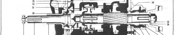
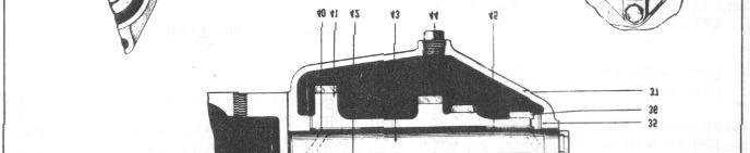
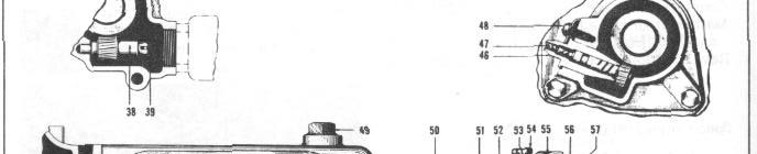
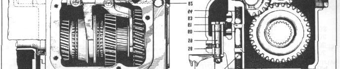
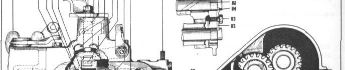
180 8-2 TRANSMISSION FIGURE 1
181 TRANSMISSION Gear Pilot Bearing 2. Main Drive Gear 3. Gear Bearing Retainer 4. Gear Oil Seal 5. Retainer Locating Pin 6. Clutch Housing 7. Bearing Retainer Ring 8. Gear Bearing 9. Shaft Pilot Bearing 10. Shift Hub Lock Ring 11. Synchronizer Shift Sleeve Hub 12. Synchronizer Spring (2 places) 13. Synchronizer Shift Plate 14. Synchronizer Shift Sleeve 15. Synchronizer Ring (2 places) 16. Shaft Intermediate Gear 17. Main Shaft 18. Low and Reverse Gear 19. Gear Housing Gasket 20. Speedometer Gear Housing Washer 21. Gear Housing Bolt (3 places) 22. Shaft Rear Bearing 23. Speedometer Gear 24. Speedometer Gear Housing 25. Gear Housing Oil Seal 26. Companion Flange 27. Flange Washer 28. Flange Nut 29. Gear Lock Ring FIGURE Retainer Gasket 31. Case Gasket 32. Washer Pin Front 33. Main Shaft Bearing Snap Ring 34. Cluster Thrust Washer 35. Cluster Steel Washer 36. Transmission Case 37. Governor Gear Overdrive 38. Governor Gear Ring Overdrive 39. Cluster Bushing Front 40. Countershaft Gear Cluster 41. Main Drive Gear (Clutch gear) 42. Countershaft 43. Drain Plug 44. Cluster Bushing Rear 45. Speedometer Cable 46. Speedometer Pinion 47. Speedometer Cable Screw 48. Filler Plug 49. Selector Lever Outer 50. Selector Shaft Nut 51. Rail Lock Ball (2 places) 52. Rail Lock Spring Low and Reverse 53. Cover Screw 54. Transmission Cover 55. Cover Gasket 56. Low and Reverse Shift Rail 57. Bushing Set Screw 58. Shift Selector Lever 59. Shift Rail Interlock 60. Selector Shaft Bushing 61. Breather 62. High and Second Shift Rail 63. High and Second Ball Spring 64. Clutch Throw Out Lever 65. High and Second Rail Stop Screw 66. Low and Reverse Shifter 67. Low and Reverse Shifter Set Screw 68. High and Second Shift Fork 69. Shift Lever Outer 70. Shift Shaft Nut 71. Shift Shaft Seal 72. Shift Shaft 73. Shift Shaft Pin 74. Shifter Control Wire Bracket Screw 75. Shift Lever, Inner 76. Low and Reverse Fork Set Screw 77. Low and Reverse Shift Fork 78. Case Stud 79. Expansion Plug 80. Washer Pin Rear 82. Counter Shaft Lock Plate 83. Lock Plate Screw 84. Idler Gear Bushing 85. Idler Gear Shaft 86. Reverse Idler Gear

182 8-4 TRANSMISSION LUBRICATION When transmission and gears are free of all lubricant, 2-1/4 pints are required to bring level up to full. When drained and refilled, 2 pints are required. The correct lubricant is an S.A.E. 90 E.P. for summer or temperatures above 32 F. and an S.A.E. 80 E.P. for winter - - or temperatures below 32 F. TRANMISSION REMOVAL FROM CAR 1. Remove front seat cushion, and remove the four bolts attaching the bottom of front seat frame to seat track. Remove two screws attaching seat adjusting lever to seat frame and remove seat back from car. 2. Disconnect accelerator pedal at accelerator rod and remove foot brake pedal rod from brake lever. 3. Pull the steering column hole rubber grommet up out of the way and remove the floor mat. 4. Remove Hudson Weather Control blower unit held by 4 screws (2 each side). 5. Disconnect the front universal joint at transmission. Loosen bolt attaching center bearing support bracket and move propeller shaft rearward to clear transmission companion flange. CAUTION: Place a block of wood under head of jack to prevent damage to the oil pan. 11. Disconnect speedometer cable at transmission and Install wood plug. 12. Remove the two top screws holding clutch housing to engine and plate and Install two headless screws or studs to support the transmission until the balance of the screws are removed. 13. Remove breather pipe bracket from clutch housing and bolt attaching breather pipe and rear tappet cover. 14. Pull transmission and clutch housing back towards the rear and up through the floor opening. Hoist J-1502 will be helpful in handling the assembly. DISASSEMBLY OF TRANSMISSION NOTE: Refer to the Overdrive Section for removal of overdrive unit on cars so equipped. Unless otherwise specified, all reference numbers in text are illustrated in Figures 1 and Remove the six screws that hold clutch housing to the transmission case and detach the clutch housing and attached clutch throwout shaft, yoke, sleeve and bearing assembly from the transmission. 2. Remove drain plug at bottom of case and drain lubricant. Place case assembly in Holding Fixture and bolt securely at front end of case with two clutch housing cap screws, Figure 3. NOTE: Use tape or rubber band to hold needle bearings in position. 6. Disconnect the clutch pedal lever return spring and remove the two clutch cross shaft bracket. 7. Remove the clutch control link clevis pin and unhook clevis. 8. Remove shifter shaft outer lever, nut and washer; this will disconnect the linkage connecting the Gear Shift to the transmission. 9. Remove 2 screws and remove flywheel guard from bottom of clutch housing and remove the two engine rear mounting bolts and nuts at #3 crossmember. 10. Jack up rear end of engine about 1/2" off the frame. FIGURE 3


183 TRANSMISSION Remove governor at speedometer gear housing on cars equipped with Over-drive, Drive Master or Vacumotive Drive. 4. Remove universal joint companion flange nut and companion flange from mainshaft. DO NOT HAMMER: Use Universal Joint Companion Flange Puller, Tool No. J-820, to remove a tight flange from mainshaft, Figure 3. "DO NOT USE A TAPERED BLADE SCREW DRIVER." 10. Slide low and reverse shift rail out of front of case, then remove shift fork and shifter, also the shift rail interlock. 11. Remove the set screw from 2nd and high shift fork, then slide the shift rail out of front of case. Remove the lock ball and spring from case. 5. Remove four screws and lockwashers and lift transmission cover off cautiously to prevent the shift rail lock spring from jumping out. Remove the spring and lock ball. 6. Flush out and thoroughly clean inside of case and gears. 7. Re move speedometer gear housing cap screws and speedometer gear housing using care to prevent damaging the housing oil seal. Remove the speedometer drive gear. 8. Remove 2nd and high shift rail stop screw. FIGURE Remove screw and countershaft and reverse idler gear shaft lock plate, Figure (5). FIGURE 4 9. Remove lock screw from low speed shifter fork an d lock screw from the low speed shifter, Figure 4. NOTE: To remove these special self-locking screws, use a screw-driver having a straight blade or a blade with a slightly reverse taper will enter to bottom of screw slot. FIGURE Drive countershaft out of rear end of case with Bronze Driver J-1574, Figure 6. Countershaft gear can now be lowered to bottom of case.


184 8-6 TRANSMISSION 14. Pull main shaft rearward by hand far enough to provide clearance for bearing puller jaws behind bearing or bearing retainer snap ring. If shaft does not move rearward easily, temporarily reinstall the companion flange and with a soft hammer tap the flange carefully rearward until above clearance is obtained FIGURE 9 FIGURE Pull bearing from mainshaft with puller J-1134-H, Figure 7. b. Remove shift sleeve hub lock ring with special pliers, KMO-630, Figure Pull main drive gear forward far enough to clear bearing retainer snap ring. Remove snap ring, then bump the drive gear forward and lift out through cover opening in case. FIGURE Pull mainshaft rearward and main drive gear forward until mainshaft is fully withdrawn from needle roller pilot bearing in rear end of main drive gear. Move synchronizer shift sleeve into 2nd speed position and low reverse sliding gear as far rearward as it will go, then lift mainshaft assembly out through cover opening in case, Figure 8. a. Disassemble mainshaft assembly on the bench by first sliding the low reverse gear off the shaft. FIGURE 10 a. To remove the bearing from main drive gear, remove the main drive gear lock ring. Figure 10.
185 TRANSMISSION 8-7 washer, and two bronze thrust washers through cover opening, Figure Working through mainshaft bearing hole in front face of case drive-out reverse idler gear shaft with Driver J-1574, Figure 13. When shaft is driven all the way out, lift reverse idler gear from case. 21. Remove shift selector shaft nut and washers, lift off selector outer lever. FIGURE 11 b: Remove main drive gear bearing using Puller J-1134-H with cup type, adaptor on puller screw, Figure 11. FIGURE 14 FIGURE Remove shift selector shaft se t screw, Figure Remove shift shaft inner lever. 19. Remove countershaft gear cluster, one thick steel thrust FIGURE 13 FIGURE 15


 between the jaws and drive out seal assembly, Figure 18.")


186 8-8 TRANSMISSION 23. Remove shift selector shaft from inside of case. Remove steel bushing by pulling upward, Figure Remove shift shaft outer lever after removing nut and washers. 27. With retainer removed from case, insert the two seal engaging jaws of Oil Seal Remover J-1576, one at a time between metal portion of seal and retainer. Place the drift (part of remover set) between the jaws and drive out seal assembly, Figure 18. FIGURE Remove shift shaft tapered pin, Figure 16, with pin punch and then withdraw shift shaft and shaft seal. REPLACING MAIN DRIVE GEAR OIL SEAL FIGURE Install new oil seal by pressing into place with tool T-1569, Figure Remove main drive gear bearing retainer by bumping it rearward out of housing, Figure 17. FIGURE 19 INSPECTION AND REPAIR TRANSMISSION CASE BREATHER FIGURE 17 When transmission has been completely disassembled, always wash and blow out the interior f re e from any grit or metallic particles. Carefully inspect the breather for being
187 TRANSMISSION 8-9 open, clean and the top sufficiently loose so that it may be rotated. The breather must be Installed so that the holes in the side of the body are fore and aft, and extend entirely through the top wall of the case, as shown in the illustration below, Figure 20. Transmission mainshaft bearings are built originally with end play and because they may feel quite loose, it does not necessarily indicate that they are worn and unfit for use. COUNTERSHAFT GEAR CLUSTER ASSEMBLY: Inspect all gears on cluster for damaged teeth. Remove any and all raised edges from teeth surfaces by hand stoning. Recommended diametrical clearance between countershaft and bore of cluster bushing is.001" to.0025". Replace bushings if clearance is greater than.005". Bushings can be removed with any suitable arbor press and driver. Should a new cluster gear be Installed, be sure that large gear (at driven end) has 26 teeth which is of the correct ratio and matches the 17 tooth Main Drive Gear. COVER BAFFLE: FIGURE 20 The baffle plate welded to the transmission cover should be so arranged as to almost touch the case boss when cover screws are Installed. Bend baffle to obtain this position. TRANSMISSION BALL BEARINGS: DO NOT place bearings where dirt is liable to mix with the lubricant in the bearing. Bearings should be washed in clean gasoline or kerosene. DO NOT SPIN the bearings and particularly do not spin bearings with an air hose. Spinning a bearing at high speeds will almost certainly do considerable damage. After washing the bearings, blow them out with clean, dry air. Direct the flow of air into the open face of the bearing while holding the inner race and slowly rotate the outer race by hand. DO NOT ALLOW the air to spin the bearing. a. Inspect the bearings for cracks, chipped balls, race and cone. b. Lubricate the bearing with clean, new engine oil, rotating the bearings by hand in order to spread the lubricant over all surface. To replace cluster bushings, place both bushings in position in the gear cluster, being sure that the annular groove in each bushing is nearest the adjacent end of shaft. Install with Bushing Replacer J-1572, Figure 20, and turn until both bushings are drawn into gear to FIGURE 21 within.015" beyond each end of gear thrust face. Insert loose pilot guide of Reamer KMO-338 in one end of gear cluster and ream bushing to.865", Figure 22. Insert removable pilot inbore of reamed bushings and ream remaining bushing from opposite end of gear.


188 8-10 TRANSMISSION SPEEDOMETER GEAR HOUSING SEAL If the seal is hard, cracked, or glazed or if signs of oil leakage are apparent at disassembly, Install a new seal. REASSEMBLY OF TRANSMISSION SELECTOR AND SHIFT SHAFT LEVERS REVERSE IDLER GEAR: FIGURE 22 Recommended diametrical clearance between idler shaft and bore of idler gear bushings is.001" to.0025". Replace bushing if clearance is in excess of.005". Start new bushing into gear bore, then pull bushing into position with Bushing Replacer J Ream bushing to.865" using Reamer KMO-338 with pilot, Figure Make sure the transmission case is thoroughly clean inside and outside. 2. From inside the case, Install the shift selector shaft bushing. Apply a few drops of oil on shaft, then insert the shaft in the bushing. Install set screw. 3. Place out e r selector lever in position (pointing toward left of case), Install plain washer, shakeproof washer and nut and tighten securely. 4. Apply a few drops of oil to shift-shaft, then insert shaft in case and lock in position with shift-shaft pin, Figure 15. Install the rubber sealing washer, outer shift lever, plain washer, shakeproof washer, and nut and tighten securely. If more than a slight drag is felt when rotating shaft, check oil seal for interference. 5. Install shift shaft inner lever on the splined shift shaft with the lever in straight up position. REVERSE IDLER GEAR AND GEAR CLUSTER FIGURE 23 SELECTOR AND SHIFT SHAFTS Recommended clearance between selector shaft and bushing is.001" to.0035", but clearance of twice this amount if not accompanied by oil leakage is permissible. If a new shift shaft seal is Installed, make sure that it does not interfere with rotation of the shift shaft. Place reverse idler gear in position inside of case after applying a few drops of oil to gear bushing. Insert one end of idler shaft with countershaft lock plate into slot in shaft. Sight through hole in lock plate and when same is centered over hole for lock screw, start reverse idler shaft into hole in case. Holding shaft in this position, bump shaft into case. When shaft is well started, apply a coat of red lead or other suitable sealer to exposed portion of shaft and drive shaft into final position with a soft hammer. Coat the two thin countershaft gear cluster thrust washers with viscous grease, then Install these washers on the retaining pins and Install in case with the bronze surface of washer

189 TRANSMISSION 8-11 towards gear thrust face. Install steel washer on rear face of cluster gear with lug on washer engaging slot in end of cluster gear. Apply light oil to bushings in cluster gear. Then place cluster gear and steel washer unit into transmission case, being careful not to dislodge the thrust washers. NOTE: Replace scored or worn washers in order to maintain proper clearance. DO NOT Install the countershaft at this time. MAIN DRIVE GEAR: Install bearing to main drive gear using Bearing Replacer J Note position of retainer ring groove. DO NOT Install RETAINER RING AT THIS TIME. Insert gear and bearing assembly through cover opening into front opening of case far enough to expose the ring retainer groove, then Install the snap ring into groove. Apply a coating of viscous grease to recess in end of main drive gear and insert the 16 individual rollers comprising the pilot bearing. If necessary to replace the stop ring proceed as follows: 1. Straighten the eight locking ears of the stop ring. 2. Remove lock ring and ring center (die case). 3. Insert the new stop ring and ring centers and turn ring center in the stop ring 1/4 turn to line up recesses in the ring center with the 8 locking ears on the stop ring. 4. Install wire lock ring and bend all locking ears in recesses as shown in the preceding illustration. NOTE: Use a small drift and a light hammer for this operation. MAIN SHAFT ASSEMBLY: 1. Install the low reverse gear to main shaft splines with oil holes in gear registered over shaft spline oil channels. Shift fork flange on gear should be toward front of shaft. NOTE: Four of the helical splines are provided with an oil channel at the front end of the splines. 2. Slide intermediate gear over front end of shaft with ground tapered hub toward front of shaft. FIGURE 25 FIGURE 24 ASSEMBLY OF SYNCHRONIZER: 1. Place the 3 synchronizer shift plates in the shift sleeve hub. Install the two synchronizer springs so that one end of each spring rests in the same groove of shift plate with the free ends running in opposite directions, Figure Assemble the synchronizer hub, plates and springs into shift sleeve. NOTE: Undercut on hub and shifter fork groove in sleeve should point toward rear of transmission.

190 8-12 TRANSMISSION 5. Assemble the two bronze synchronizer rings to the shift sleeve hub with the 3 plate end slots engaging the shift plates. 6. Install the synchronizer unit on the main shaft with the tapered side of the shift sleeve toward the front of the transmission. 7. Install synchronizer shift sleeve hub lock ring on end of main shaft using Pliers J USE A NEW LOCK RING. The lock ring is available in only one thickness.087" and must be carefully fitted into shaft groove to eliminate all end play. 8. Move the synchronizer shift sleeve towards rear of mainshaft (2nd gear position), then carefully insert mainshaft and gears assembly through cover opening of case with threaded end of mainshaft towards rear of case. Carefully enter the front end of mainshaft into pilot bearing mounted in end of main drive gear. 9. Install the speedometer gear housing over the mainshaft bearing and with 3 bolts 1/2" longer than the standard bolts removed, draw the bearing on the shaft carefully with even pressure until speedometer gear housing contacts the transmission case. Remove the speedometer gear housing. 10. Install the speedometer drive gear to rear end of mainshaft. thrust washers are properly positioned) and then insert beveled end of countershaft into case and gear cluster from rear end of case. Drive Countershaft forward with a soft hammer and when it is within 1-1/2" of being fully entered, apply a coating of red lead to exposed portion. SHAFT MUST BE TURNED TO CORRECT POSITION FOR Installation OF LOCK PLATE AND FRONT THRUST WASHER ALIGNED WITH HOLE IN CASE. Drive shaft all the way forward and Install the lock plate and screw, tighten securely. SHIFTER RAILS AND FORKS 1. Install the shift rail lock ball spring and lock ball into hole in case. LOW AND REVERSE RAIL 2ND AND HIGH RAIL STANDARD TRANSMISSION 9 lbs. 9 lbs. WITH OVERDRIVE 30 lbs. 19 lbs. NOTE: On cars equipped with the first series standard transmission the low and reverse r shift rai I lock ball spring tension is 9 lbs. when compressed to 11/16". The second and high shift rail spring tension is 11 lbs. at 7/8". On overdrive equipped cars the low and reverse shift rail lock ball spring is 30 lbs. when compressed to 13/16". The second and high shift rail spring tension is 19 lbs. at 11/16". 11. Install speedometer gear housing assembly and new gasket to end of case. 12. Install the companion flange being careful to prevent injury to the oil seal. Install plain washer and self-locking nut. Tighten to foot pounds using a torque wrench. THIS NUT MUST BE KEPT TIGHT. COUNTERSHAFT Insert Countershaft Driver J-1574 into countershaft cluster gear through hole in front end of case. Raise cluster gear up into alignment (determining that the front and rear FIGURE 26

191 TRANSMISSION Place second and high shift fork in groove of synchronizer shift sleeve and while holding the fork in this position, insert the shift rail into case through hole in fork, Figure 27. Install and tighten slotted set screw using a straight blade screwdriver. Install rail stop screw and lock washer. NOTE: The rail stop screw must not bottom on shift rail. CAUTION: Make sure at this time that t he previously Installed inner shift shaft lever is correctly positioned. Inner shift lever and milled end of shift shaft should be in a true vertical position. 3. Install shift rail interlock plunger. FIGURE 28 Install clutch bell housing, (use new gasket). Tighten each of the 6 cap screws to 45 foot pounds. Install drain plug and insert 2-1/4 pounds of S.A.E. 80 E.P. Winter or S.A.E. 90 E.P. Summer lubricant through filler plug opening. Install and tighten filler plug. InstallING TRANSMISSION FIGURE Start the low and reverse shift rail, into transmission case. Install low and reverse shifter in position and slide shift rail into shifter, Figure Place low and reverse shift fork in groove of low and reverse sliding gear and slide shift rail through hole in fork and into hole at end of case. 6. Install slotted head lock screw into shifter and tighten securely. Follow the same procedure on shift fork and lock screw. 7. Shift transmission into all 4 gear positions successively and also into neutral. If operation is satisfactory Install the remaining shift rail lock ball and lock spring. 8. Install transmission cover using a new gasket. 1. Install two headless screws or studs in engine end plate to assist in supporting the the transmission at Installation. NOTE: Before Installing transmission to engine rear support plate, check cylinder block rear support plate very carefully for tightness and alignment. This is especially important in cases where the car has been subject to chronic transmission trouble, noisy and jumping out of gear. Make a similar check of transmission clutch bell housing. In lieu of highly precise equipment, use a steel straightedge to check steel rear support plate and a surface plate or other flat surface to check the front face of clutch bell housing. Both units should be flat and in plane within.005". Be sure to check position of clutch driving plate and see that it is perfectly centralized within the clutch assembly. This can be done by using the J-449 aligning arbor or with a standard main drive gear if arbor is not available. If this precaution is not taken, difficulty will be encountered when
192 8-14 TRANSMISSION Installing the trans-mission and the front end of the drive gear shaft and pilot bearing in the flywheel will be damaged. 2. Rotate clutch collar and throwout bearing to position for proper alignment with throw-out yoke on transmission. 3. Tighten all rear engine support plate to block screws. 4. Bring the transmission assembly to position where the main drive gear (clutch shaft) is aligned with bore of clutch throwout collar, then carefully push transmission forward to enter drive gear splined shaft through grease retainer leather washer, splines of clutch driving plate and into pilot bearing in flywheel. NOTE: During this operation the main drive gear must be relieved of all over hanging weight of the transmission until the bell housing engages the dowels on engine rear support plate. Be f or e transmission assembly is moved up against rear support plate make a last inspection to verify that end face of throwout collar in clutch is properly aligned with throwout yoke on transmission and that oil seal lip has not turned under. CAUTION: Alignment of bell housing with engine is controlled by the sleeve dowel in the upper left location of the bell housing attaching bolt circle and by the dowel bolt at the lower right location viewed from rear of car. Make sure that the former is in place and entered in bell housing hole before tightening bolts. Install lower right bolt (dowel bolt) first. NEVER grind or otherwise reduce the diameter of the dowel bolt to facilitate Installation. 5. Remove the two headless screws or guide studs, J Install remaining clutch bell housing bolts and screws and tighten with a torque wrench to foot pounds. 7. Complete remainder of Installation by reversing the order of removal of the remaining parts. TROUBLE SHOOTING SERVICING THE TRANSMISSION JUMPING OUT OF GEAR Jumping out of gear is likely to be caused by one of the following conditions: 1. Misalignment of the transmission with the engine (chips, dirt, buckled gasket) between the clutch bell housing and transmission may cause jumping out of high gear. 2. Engine mountings improperly adjusted may cause jumping out of high gear. 3. Mainshaft or countershaft end play is excessive, might cause jumping out of high or second. 4. Synchronizing unit worn or damaged. 5. Loose fitting bearings or bushings. 6. Failure to move gearshift lever far enough to complete engagement. 7. Low and reverse shift rail lock ball spring lacks sufficient tension. See chart under "Shifter Rails and Forks" Page NOTE: If transmission has jumped out of gear many times while under load, it may be necessary to replace the mating gears because the gear teeth may have become beveled. NOISE IN GEAR Misalignment of transmission Worn, scored countershaft bushings Worn, rough reverse idler gear Eccentric countershaft gear assembly Sprung or worn countershaft Excessive backlash in constant mesh gear Excessive end play in countershaft or reverse idler gear Worn mainshaft pilot bearing Scuffed gear tooth contact surface Insufficient lubrication Incorrect grade of lubricant
193 TRANSMISSION 8-15 Worn, rough mainshaft rear bearing Sliding gear teeth rough, chipped, tapered Excessive second speed mainshaft end play Noisy speedometer gears Noise may occur in neutral or in any one or more speeds. Some gear noise is to be expected in all except high speed. Trace the gears that are under load and examine them for damage, checking the bearings and amount of end play. Noise in neutral in the form of a constant regular click indicates a nicked gear of faulty bearing. End play on countershaft to be not less than.006" nor more than.016". If a check shows end play of more than.016" t indicates worn thrust washers that should be replaced. End play on mainshaft intermediate gear and synchronizer shift sleeve to be from.003" to.006" and if more than.016" it indicates a worn synchronizer shift sleeve hub lock ring that needs replacing. End play on the reverse idler gear is from.003" to.010" and any end play in excess of.010" requires replacement of gear. OTHER NOISE CAUSES Out-of-balance fan Defective torsional damper Out-of-balance flywheel Unbalanced clutch assembly Loose transmission mounting Loose engine mountings Worn universal joints U-joints improperly Installed Misaligned or sprung propellor shaft Incorrect driveshaft assembly STICKING IN GEAR Improperly operating clutch Insufficient chamfer on shift rail ball notches Sliding gear tight on mainshaft splines Misaligned mainshaft Improper linkage adjustment SLIPPING OUT OF FIRST GEAR First and reverse sliding gear loose on main-shaft splines Sliding gear teeth worn or tapered Worn, misaligned mainshaft splines Worn countershaft first speed gear Excessive end play of reverse idler Insufficient gear mesh Too much chamfer on shift rail ball notch Improper linkage adjustment LOSS OF LUBRICANT Lubricant level too high Damaged or improperly Installed gaskets Damaged or defective oil seals Loose drain plug, transmission cover Cracked transmission housing Use of excessively foaming lubricant Stopped up transmission breather Worn mainshaft bearings HARD SHIFTING Improperly operating clutch Sliding gear tight on shaft splines Insufficient chamfer of sliding gear teeth Burred mainshaft splines Misaligned mainshaft Damaged synchronizing unit Worn shifter rails Worn or sprung shifter fork Improper adjustment of shifting linkage Difficult gear shifting, especially into second gear, is often caused by the improper adjustment of the cross-shift control wire or by looseness of the cable anchor clip which secures it to the bell housing. This results in insufficient movement being imparted to the transmission inner shift shaft lever to allow it to fully engage the shift forks. In cases of hard shifting the "Gear Shift" lever and cross shift control cable should be adjusted if necessary as follows: A. Place "Gear Shift" Control Lever, Figure 29 in the extreme upper position. B. Loosen control wire casing anchor bracket bolt. Pull upper anchor bracket (18) up' until all slack is out of casing and the shift shaft inner lever is fully over into the low and reverse shifter. (Check this in transmission). Tighten anchor bracket bolt (35) Figure 30. The control wire anchor should have clearance at top and bottom.
194 8-16 TRANSMISSION FIGURE Control Lever 2. Control Lever Knob 3. Control Lever Anti-Rattle Washer 4. Control Lever Fulcrum Screw 5. Control Lever Fulcrum Bracket 6. Control Lever Fulcrum Bracket Ring 7. Lever Tube and Fulcrum Bracket 8. Control Lever Compression Spring 9. Compression Spring Seat 10. Control Lever Tube Bracket - Upper 11. Control Lever Tube Bracket - Lower 12. Control Lever Push Rod 13. Push Rod End - Upper 14. Push Rod End - Lower 15. Push Rod Upper Compression Spring 16. Push Rod Spring Seat 17. Control Wire, Casing and Bracket 18. Control Wire Anchor Bracket - Upper 19. Control Wire Anchor Bracket - Lower 20. Control Wire Dust Boot (Steering End) 21. Control Wire Dust Boot (Trans. End) 22. Control Wire Anchor 23. Control Wire Anchor Hairpin Clip 24. Trans. Shift Selector Lever, Outer 25. Trans. Lever to Bell Crank Rod 26. Bell Crank Rod Grommet 27. Bell Crank Rod Washer 28. Bell Crank Rod Clevis 29. Control Tube Upper Bracket Set Screw 30. Bell Crank Rod Locknut 31. Push Rod End Key 32. Push Rod Lower Compression Spring 33. Control Wire Anchor Clamp Bolt 34. Control Tube Upper Bracket Clamp Bolt 35. Steering Jacket Tube Clamp 36. Control Lever to Bell Crank Rod 37. Control Crank (At Steering Gear) 38. Jacket Tube Lower Clamp
195 TRANSMISSION 8-17 NOTE: Check shift selector lever (26) Figure 30 to which cross shift control wire is attached, to be sure the lever is tight on its shaft. Check bracket (19) to be sure it is tight on the transmission case. Increased viscosity of the transmission lubricant during cold weather is another factor to be considered when dealing with hard shifting, as the thickening of the lubricant is apt to interfere with the action of the synchronizing mechanism. During cold weather operating, it is recommended that the lubricant be thinned by the addition of kerosene when hard shifting is encountered. Add approximately 2 ounces of kerosene after draining a like quantity of lubricant. C. The "Gear Shift" control should be inspected and if the gear control lever (1) Figure 30, is not in a true crosswise position when in neutral, it should be adjusted by removing the cotter pin and clevis pin at the front end of the control tube to transmission rod (27). Loosen lock nut (32) and turn clevis (30) in the rod. When properly adjusted (transmission in neutral and Gear Shift control lever exactly crosswise), the clevis pin hole in the clevis (30) will line up with the hole in lever (39). GEAR SHIFT The gear shifting mechanism is operated from a control lever pivoted in a housing attached to the steering gear jacket tube just below the steering wheel. The backward and forward movement of tide gearshift lever (1) Figure 30 imparts a rotary motion to the tube and lever (7). This rotary motion moves the control lever t o bell crank rod (38), bell crank to shift shaft outer lever rod (27) and outer shift shaft lever back and forth. The outer shift shaft lever is attached to the transmission shift shaft, an inner lever mounted on the shift shaft moves the gear into the desired positions. ADJUSTMENT Place the gear shift lever (1) in neutral position, remove the cotter pin and clevis pin from rod (27) at bell crank (39). The transmission outer shift shaft lever and the gear shift lever (1) must be in the neutral position. Loosen rod lock nut (32) on rod (27) and turn clevis (30) in or out until the clevis pin will drop into bell crank hole (39). REMOVAL GEAR SHIFT LEVER TUBE AND FULCRUM BRACKET 1. Remove horn ring and steering wheel. See Steering Gear Section. 2. Raise carpet sufficiently to clear area of steering gear. 3. Remove steering gear floor opening dust cover. 4. Remove set screw (31) and clamp bolt (36) and remove gear shift upper bracket from jacket tube. NOTE: Check condition of lever fulcrum bracket spacer ring (6) and replace if less than.025 thick. 5. Remove retainer plate at instrument panel. 6. Remove steering jacket tube clamp (37) at instrument panel. 7. Remove hair pin clip (23) attaching gear shift control cable (17) to lever (7) and remove cable anchor bracket clamp bolt (35). NOTE: When re-installing bracket (18) and cable (17) to lever tube bracket (7) the gear shift lever (1) must be in the extreme up position, (between the low and reverse positions). Pull bracket (5) and tube (7) upward until all slack is out of the casing and control wire and that the shift lever at the transmission is completely over to the low and reverse side. (To be checked at transmission). Before tightening bolt (35) assure that anchor (22) in control wire (17) has clearance at the top and bottom of travel.
196 8-18 TRANSMISSION 8. Disconnect rod (38) at control lever (7). 9. Remove spring (8) and flat washer (9). 10. Control tube can now be removed. NOTE: If Steering Gear Jacket Tube is to be removed with control tube attached proceed as follows: a. Loosen steering gear housing mounting bolts to allow steering gear to drop sufficiently to allow clearance for jacket tube removal. b. Loosen jacket tube clamp (40) at steering gear housing and lift jacket tube by swinging the lever up and to the right and out through opening at floor cover. To Install, reverse procedure of removal. REMOVAL GEAR SHIFT CONTROL LEVER PUSH ROD 1. Remove steering wheel. 2. Remove upper bracket (5) and ring (6). 3. Remove gear shift lever fulcrum screw (4), lever (1), and anti-rattle spring washer (3). 4. Remove hairpin clip anchor (22) at lower end of control tube and disconnect cable (17). 5. Remove bolt (35) attaching anchor bracket to lower support bracket. 6. Pull lower push rod end (14) down far enough to remove the key attaching push rod (12) to push rod end (13). 7. Remove push rod upper end (13). 8. Remove upper compression spring (15) and seat (16) with a wire hook. Installation Install the upper compression spring seat (16) and spring (15) on the push rod (12) and Install in control tube (17). NOTE: Apply a coat of viscous chassis lubricant to the push rod ends when assembling them in the control tube. Reverse procedure of removal on remaining parts. Source of Information Date REFERENCE Subject
197 TRANSMISSION 8-19 SECTION 8 TRANSMISSION (Manual Type Double Shift Lever) CONSTRUCTION It is of the all-helical gear type with synchro-mesh second and high gears. The rear of the mainshaft drive gear is supported by a ball bearing mounted on its case and the front end is piloted by a ball bearing in the flywheel. The front end of the mainshaft operates in rollers carried in the mainshaft drive gear and the rear end is supported by a ball bearing in the case. Oil retention is by means of hydraulic leather oil seals in the drive gear and rear bearing retainers. The mainshaft second speed gear and the reverse idler gear operate on their shafts through precision fitted, bronze alloy bushings. The countershaft gear cluster operates on the stationary countershaft through needle rollers at each end held in position by a spacer tube and washers. Countershaft gear cluster end thrust is taken by a single stationary, bronze faced thrust washer at the front and by a rotating bronze washer and a stationary steel washer at the rear. Separate shift shafts with integral cams on the inside and actuating levers on the outside, operate the low and reverse and second and high gears through forks and an interlock arrangement common to both shafts. Separate rubber mounted rods connect the outer shift shaft levers to the two levers on the transmission control. The transmission is mounted on the clutch housing with four bolts passing through lugs on the case from the rear into the clutch housing. This simplifies transmission removal and replacement since the clutch housing and floor cover do not have to be disturbed. Positioning of the transmission on the clutch housing is through the main drive gear bearing retainer, the outside of which is a close fit in the hole machined in the clutch housing. Breathing or venting is through a small opening in the front of the cover and two holes in the rear of the gasket, which is held away from the cover at the center by a depression stamped in the cover. Low Second High Reverse SPECIFICATIONS GEAR RATIO GASKET THICKNESSES Drive Gear Bearing Retainer:.010",.015",.020" and.025" Rear Bearing Retainer:.010",.015",.020" and.025" SNAP RING THICKNESSES Mainshaft Drive Gear Bearing:.087",.090",.093" and.096" Mainshaft Rear Bearing:.087",.090",.093" and.096" Mainshaft Drive Gear:.087",.090",.093",.096" and.101" MARKING "A" "B" "C" D" No Mark INTERLOCK SLEEVES LENGTH " 1.287" 1.303" 1.299" LUBRICATION: 2-1/4 Pts. S.A.E.-90 Summer, S.A.E. -80 Winter, Gear Oil to to to to 1
198 8-20 TRANSMISSION FIGURE 10
 15. C. S. Gear Cluster 16. C. S. Rear Thrust Washer (Inner) 17.")
199 TRANSMISSION Synchronizer Rings 2. Synchronizer Springs 3. Synchronizer Hub 4. Synchronizer Shift Plates 5. Synchronizer Sleeve 6. Cover 7. Cover Gasket 8. Mainshaft Snap Ring 9. Synchronizer Assembly 10. Second Speed Gear and Bushing 11. Low and Reverse Gear 12. Mainshaft Front Rollers 13. Mainshaft 14. C. S. Thrust Washer (Front) 15. C. S. Gear Cluster 16. C. S. Rear Thrust Washer (Inner) 17. C. S. Rear Thrust Washer (Outer) 18. C. S. Bearing Washers 19. C. S. Gear Spacer 20. C. S. Bearing Rollers FIGURE Countershaft 22. Reverse Idler Gear 23. Reverse Idler Gear Bushing 24. Reverse Idler Gear Shaft 25. Idler and C. S. Lock Plate 26. Main Drive Gear Bearing Retainer 27. Main Drive Gear Oil Seal 28. Math Drive Gear Snap Ring 29. Main Drive Gear Bearing Snap Ring 30. Main Drive Gear Bearing 31. Main Drive Gear Oil Retaining Washer 32. Main Drive Gear 33. Main Drive Gear Bearing Retainer Gasket 34. Transmission Case 35. Mainshaft Bearing (Rear) 36. Mainshaft Bearing Snap Ring 37. Mainshaft Rear Bearing Retainer Gasket 38. Mainshaft Rear Bearing Retainer 39. Retainer Bolts 40. Speedometer Drive Gear 41. Mainshaft Oil Seal 42. Companion Flange 43. Mainshaft Plain Washer 44. Mainshaft Lock Washer 45. Mainshaft Nut 46. Shift Fork (Second and High) 47. Taper Pin 48. Shift Shoe (Low and Reverse) 49. Shift Shaft (Second and High) 50. Shift Lever Interlock Sleeve 51. Shift Shaft (Low and Reverse) 52. Shift Rail Lock Ball 53. Shift Rail Lock Ball Spring 54. Shift Shaft Oil Seals 55. Shift Lever Interlock Pin 56. Control Lever Outer Clevis Pin 57. Second and High Control Lever (Outer) 58. Low and Reverse Control Lever (Outer)
200 8-22 TRANSMISSION REMOVAL: The transmission is removable from underneath the car, thus eliminating the operation of removing and replacing the floor cover and mat. The clutch housing also does not have to be disturbed. 1. Remove drain plug and drain lubricant. 2. Remove nuts, washers and clamps from front universal joint and disconnect propeller shaft. Use tape passed around both bearing cups to hold bearing cups and needle rollers in place and prevent entry of dirt. 3. Disconnect low and reverse and high and intermediate shift rods at transmission shift levers. 4. Disconnect speedometer cable at transmission and remove speedometer pinion. 5. Remove nut from front end of brake pivot brace at No. 3 crossmember. 6. Remove clevis pin at rear end of brace and move linkage to left side of car. The additional clearance gained will aid in lowering and removing the transmission. 7. With a universal socket on a 10" extension, remove the two top bolts attaching transmission to clutch housing. Insert in their places guide studs (J-2969) to guide transmission during removal. FIGURE Remove four bolts from mainshaft rear bearing retainer and take off retainer and gasket. Remove speedometer drive gear from mainshaft. 5. Remove three bolts holding main drive gear bearing retainer and take off retainer and gasket. 6. Remove small snap ring from main drive gear. 7. With a brass drift and hammer, move countershaft rearward just enough to free up the lock plate in the shaft groove at the rear end, Figure Lower transmission and clean outside thoroughly before placing it on workbench or holding fixture for disassembly. DISASSEMBLY : 1. Remove six screws holding cover and take off cover and gasket. 2. Holding universal joint companion flange with holding tool (J-2637), remove main-shaft nut, lock washer and plain washer. 3. Remove companion flange, using puller (J-820), Figure 32. FIGURE 33


201 TRANSMISSION Make a dummy countershaft of 3/4" diameter cold rolled steel exactly 7-5/64" long with a 3/16" hole drilled 1" deep at each end. The purpose of the dummy shaft is to retain in position the needle rollers, sleeve and thrust washers when removing or Installing countershaft gear cluster. 9. To lower the countershaft gear cluster to the bottom of the case to permit removal of main drive gear assembly and main-shaft, place end of dummy shaft against front end of countershaft and with a soft hammer, carefully drive countershaft rearward out of the transmission case. Make sure the dummy shaft remains in constant contact with the countershaft during this operation, otherwise the thrust washers, needle rollers and other parts will fall out of place. 10. With a small, pointed brush, paint a fine line across the synchronizer rings, sleeve and second and high mainshaft gear to insure replacement of these parts in their proper positions, Figure 34. FIGURE Holding synchronizer parts and second and low gears together as a unit, move mainshaft to right and disengage shifter fork and shoe from grooves in shifter sleeve and low gear. Twist and withdraw mainshaft through rear of case, Figure 36. FIGURE To remove main drive gear, place a brass bar or drift against the rear face of the drive gear teeth at the top (not synchronizer gear teeth) and carefully drive gear and bearing forward out of case. 12. With a brass bar placed against front end of mainshaft, drive mainshaft rear bearing out through rear of transmission case. 13. Using snap ring pliers, remove snap ring from front end of mainshaft, Figure 35. FIGURE With a long brass drift drive reverse idler gear shaft out of rear of transmission case and remove idler gear. 16. Lift countershaft gear cluster with dummy shaft holding needle rollers and other parts in position, straight up out of case. Carefully remove. the thrust washers and note position to insure exact replacement. 17. With a punch, drive taper pins securing shift shafts in position, upward out of case, Figure 37.


202 8-24 TRANSMISSION To renew mainshaft rear oil seal, drive old part out of rear flange and Install new seal, tapping it into rear bearing retainer from rear. The seal is properly Installed when the rear face projects 1/4" beyond the retainer. The shift shaft oil seals are renewed by driving out the old seals from the inside of the case with a punch and tapping the new ones in place from the outside. FIGURE Remove nuts, washers and levers from shift shafts and take shafts out of case. When doing this, also remove interlock sleeve, detent balls, spring and pin. INSPECTION : At this stage thoroughly clean and carefully inspect all parts for wear or damage necessitating further disassembly and parts replacement. Regardless of appearance, all gaskets and the oil seals at the main drive gear, rear end of mainshaft and shift shafts should be renewed during reassembly. NOTE: When Installing oil seals, coat outside of seal and inside of housing with red or white lead or gasket sealer to insure leak-tight joints. Soak leather seals in light engine oil for 24 hours preparatory to using. The mainshaft second speed gear and the reverse idler gear are fitted with bushings which are precision machined to close tolerances after pressing in place. Since replacement of the bushings in the field is not practicable, it is necessary to replace the gear assemblies in event of excessive wear or looseness. FIGURE 39 FIGURE 38 To remove drive gear bearing oil seal, drive out with driver (K-224). Install new oil seal with oil seal replacer (J-1569), Figure 38. If inspection of the mainshaft drive gear or the mainshaft rear ball bearings shows excessive roughness, wear or damage, they should be replaced, using bearing puller (J-1134-H) for removal, Figure 39 and (J-1570) Replacer for Installation, Figure 40, of new bearings


203 TRANSMISSION 8-25 center of the case to its correct position. FIGURE Install shift shaft levers, short (low and reverse) on rear shaft and long (second and high) on front shaft. Move either lever into any in-gear position and with one end of the interlock sleeve contacting a shift shaft cam, measure the clearance with a feeler gauge between the opposite end of the sleeve and the cam of the other shift shaft, Figure 42. This clearance should be from.001" to.007". If not within these limits, remove sleeve and replace with one of proper length. Interlock sleeves are available in five different lengths as shown in specifications. Install taper pin retaining second and high shift shaft in case. REASSEMBLY SHIFT SHAFTS AND INTERLOCK 1. Install low and reverse shift shaft in case, using care not to damage the oil seal. Align neutral detent of shift shaft cam with interlock opening in case, and Install the retaining pin in case. 2. Insert interlock sleeve in case and Install within interlock in the following order: one of the interlock balls, interlock spring and interlock pin with ball resting in neutral groove of shift shaft cam, Figure 41. FIGURE 42 COUNTERSHAFT GEAR CLUSTER 1. To Install countershaft gear cluster assembly, place needle roller spacer tube over dummy shaft and insert in cluster. Apply viscous grease between shaft and inside of gear at each end and place needle roller washers in position against each end of spacer tube. Next, insert needle rollers (22) between inside of gear and dummy shaft, followed by a retaining washer at each end. FIGURE Install second and high shift shaft in case, using care not to damage the oil seal and push the shaft in as far as possible. Install the other interlock ball by inserting it in the interlock sleeve, compressing the spring and at the same time sliding the second and high shaft toward the 2. Coat countershaft thrust washers and ends of cluster with viscous grease and place washers in position. Install front washer with bronze face to gear and lug at top. The rear inner (bronze) thrust washer should be Installed so the lugs will engage the slots in the cluster gear and the outer (steel) thrust washer with the lug at top.

204 8-26 TRANSMISSION 3. Carefully lower cluster and assembled parts into position and enter front end of countershaft at rear of transmission case, tapping it forward while holding the front end of the dummy shaft in constant contact with the countershaft to keep needle rollers and washers in place. Drive countershaft forward just far enough to enter front end in case, as it must again be removed after checking end play. 4. With a feeler gauge inserted between the rear thrust washers, check countershaft cluster end play, Figure 43. End play should range between.006" and.016"; if more t FIGURE Next enter dummy shaft in front of case and by tapping on shaft with a soft hammer, drive out countershaft through rear of case, using care to keep ends of shafts together at all times. Lower countershaft cluster with dummy shaft in place, to bottom of case. REVERSE IDLER GEAR 1. Place reverse idler gear in position in case (1 on g hub toward front) and drive idler gear shaft in from rear of the case. Before fully Installing shaft, make sure slot for lock plate is properly aligned with countershaft so plate will seat in both slots. Idler gear end play should be from.003" to.010". MAINSHAFT ASSEMBLY 1. Insert mainshaft with rear bearing assembled, through rear of transmission case and Install low and reverse sliding gear, with shift collar towards front of transmission. 2. Install low and reverse fork in rear shift lever shaft (offset to front) and engage fork in groove of low sliding gear. 3. Install second speed gear. 4. Assemble synchronizer hub, shift plates, shift sleeve, springs and synchronizer rings together as a unit and slide on mainshaft splines the long hub of the sleeve pointing forward. Be sure that marks painted on parts during disassembly are in proper alignment, also that the hooked ends of the two synchronizer springs engage in the same shift plate. 5. Install snap ring on front of mainshaft and check end play by inserting a feeler gauge between the rear face of the mainshaft second speed gear and the front ends of the mainshaft spiral splines. This should be from.003" to.016". Excessive end play at this point can only be corrected by Installing new parts. 6. Install second and high shift fork in second and high shift shaft, move mainshaft and parts toward shift fork and engage fork in groove of synchronizer shift sleeve. 7. Complete Installation of mainshaft and rear bearing in case by tapping rear bearing outer race with plastic or rawhide hammer until bearing case snap ring is flush with rear of case. MAINSHAFT DRIVE GEAR ASSEMBLY 1. Coat inside of mainshaft drive gear and mainshaft front rollers with lubriplate or heavy viscous grease and assemble rollers (14) in position in gear. 2. Install mainshaft drive gear assembly tapping outer race of bearing with a plastic or rawhide hammer until snap ring in outer race is flush with front of case. When doing this, be sure rollers are not dislodged before pilot end of mainshaft enters drive gear. COUNTERSHAFT Installation 1. To Install countershaft, insert two suitable punches through countershaft holes in front and rear of transmission case,
205 TRANSMISSION 8-27 case, entering the punches in the 3/16" holes drilled in the ends of the dummy countershaft. With punches, raise the countershaft cluster until in alignment with countershaft holes in case, then insert countershaft through hole in rear of case. 2. Tap rear end of countershaft moving it forward and pushing dummy shaft out through front of case. When doing this, keep dummy and countershaft in contact with each other and line up slot in rear end of countershaft for lock plate. 3. Place lock plate in correct position engaging slots at ends of countershaft and reverse idler shafts and tap both shafts until lock plate is tightly held. DRIVE GEAR BEARING RETAINER 1. Tap front face of drive gear bearing outer race to make sure it is fully in place. 2. Install main drive gear bearing retainer with new oil seal Installed and without gasket and without screws. 3. With a feeler gauge, check clearance between rear face of retainer and front of transmission. 4. Remove retainer and select and Install a gasket.003" to.005" thicker than clearance indicated by feeler. (Gaskets are available in four different thicknesses.) 5. Place bearing retainer in position, Install 3 cap screws and tighten, making sure oil drain hole in flange is aligned with hole in case. MAINSHAFT REAR BEARING RETAINER 1. Tap rear face of mainshaft rear bearing outer race to insure tight seating of bearing against rear of case. 2. Slide speedometer drive gear on rear end of mainshaft, with hub facing forward. 3. Place rear bearing retainer with new oil seal Installed and without gasket in position at rear of transmission. DO NOT Install screws. 4. Check clearance between front of retainer and transmission case with a feeler gauge. Take off retainer. 5. Select a gasket.003" to.005" thicker than clearance shown by feeler and Install between retainer and case. 6. Install and tighten 4 cap screws holding retainer to case. 7. Place universal joint companion flange on mainshaft splines and Install plain washer, lock washer and nut. Using (J-2637) holding tool on flange, tighten mainshaft nut to a torque of ft. lbs. 8. Install transmission cover, using new gasket. The cover gasket must be positioned with the two vent holes at the rear while the cover itself is Installed with the single vent hole at the front. Install six cap screws and lock washers and tighten. TRANSMISSION Installation 1. Install two guide studs (J-2969) in upper holes of clutch housing to assist in supporting transmission during Installation. 2. Raise transmission in position entering guide studs in top holes in flange. When moving assembly forward and engaging mainshaft splines in clutch plate hub, make sure throw out bearing and collar are properly positioned with the throwout yoke fingers against the machined pads of the collar. 3. Install lower bolts holding transmission to clutch housing, then remove guide studs at top and replace upper bolts and tighten. 4. Install speedometer drive pinion and connect speedometer drive shaft. 5. Connect second and high and low and reverse shift rods to shift shaft levers on transmission. 6. Replace brake linkage brace and Install nut on front end and clevis pin at rear end. 7. Place front universal joint needle roller cups in position on companion flange, Install clamps, washers and tighten nuts. Make sure bearing cups are properly seated under retaining lugs of companion flange. 8. Tighten drain plug, remove filler plug and fill transmission to bottom of plug opening (2-1/4 lbs.) with S.A.E. 80 Winter, S.A.E. 90 Summer gear oil. Replace and tighten filler plug.
206 8-28 TRANSMISSION FIGURE 44 LEGEND 1. Bracket - Upper Control Tube 2. Washer - Thrust 3. Control Lever 4. End - Push Rod Upper 5. Bracket - Fulcrum 6. Key - Upper End 7. Control Tube 8. Spring - Push Rod Upper 9. Seat - Upper Spring 10. Push Rod 11. Silencer - Push Rod Tube 12. Key - Lower End 13. Retaining Ring - Lever 14. End - Push Rod Lower 15. Pin - Lever Operating 16. Lever Assembly - 2nd & High 17. Lever Assembly - Low and Reverse 18. Bracket - Lower Control Tube 19. Spring - Upper Compression 20. Fibre Washer 21. Spring - Lower Compression 22. Retainer - Spring 23. Bolt - Spring Retainer 24. Rod Assembly - Low & Reverse 25. Rod Assembly - 2nd & High 26. Trunnion - Rod 27. Nut - Rod 28. Pin - Locating
207 TRANSMISSION 8-29 REMOVAL AND Installation OF HANDY-SHIFT CONTROL TUBE AND FULCRUM BRACKET ASSEMBLY 1. Remove control lever fulcrum screw, lock washer and antirattle washer from fulcrum bracket (5) Figure 44, and take out control lever (3). 2. Remove dowel screw and loosen clamp screw at control tube upper lever bracket and take off bracket (1) and thrust washer (2). 3. Remove screws holding steering column bracket cap to bracket and take off cap. 4. Remove cotter pins and trunnions (26) from low and reverse and second and high levers. 5. Remove bolt (23), spring retainer (22) lower compression spring (21), fibre washer (20) and upper compression spring (19). 6. Slide low and reverse lever (17) off lower end of control tube. 7. Pull control tube (7) out of lower bracket (18) and push out control tube operating lever pin (15). Do Not loosen clamp bolt or alter position of bracket. Remove second and high lever (16) from tube. 8. Take out control tube assembly and place on bench for disassembly of remaining internal parts and reassembly into new tube. 9. Push upward on lower end of lower push rod end (14) exposing upper end of push rod (10) and push rod end (4). 10. Remove upper push rod end key (6); take off end. 11. Remove push rod and lower end assembly from bottom of control tube, take out lower rod end key (12) and remove end (14) from rod. 12. Remove seat (9), push rod upper compression spring (8) and silencer (11) from inside of tube. 13. Remove second and high lever retaining ring (13) from tube. 14. Reassemble parts in new control tube and fulcrum bracket assembly, reversing procedures covered in the foregoing operations. When Installing spring retainer (2 2), adjust retainer bolt (23) so there will be a space of 27/64" (B) between the bottom of the fibre washer (20) and the top of the retainer. Also be sure lower tube bracket (18) is centrally located between second and high and low and reverse levers. ADJUSTMENTS 1. Before making any adjustments, be sure Handy-Shift control tube is parallel with steering column jacket tube. If not parallel, loosen clamp screw in the control tube lower bracket, move bracket until alignment is obtained, then tighten clamp screw. When doing this be sure the bracket is centrally located between the second an d high and low and reverse levers as shown at "A". 2. Check adjustment of spring retainer (22). With the springs properly compressed, the distance "B" between the retainer and the bottom of the fibre washer (20) should be 27/64". 3. With control lever in neutral position, loosen the low and reverse and second and high shift rod nuts (27) at trunnions on levers. Back off nuts approximately 1/4" on each side of trunnions. 4. Insert a 1/4" diameter rod about 4" long through the holes in the low and reverse and second and high shift levers, engaging slot in control tube lower bracket (28). This locks the levers in neutral position. 5. Move the two outer shift levers on the transmission by hand to make sure the lock balls are fully seated in the neutral detents of the transmission shift shafts. 6. Turn nuts (27) on shift rods until they contact each side of the trunnions. Tighten nuts, using care not to disturb the position of the rods or the transmission shift levers.
208 8-30 TRANSMISSION 7. Remove 1/4" rod from levers. It should come out easily. 8. Check manual shift crossover by moving control lever up and down. If crossover is not smooth, shorten or lengthen shift rod attached to low and reverse lever by moving adjusting nuts at trunnion, 1/4 turn at a time, until smooth action is obtained. 9. Check gear shifting by moving control lever through the various positions. If interference or sticking is encountered when going into low or reverse, check for proper adjustment of the spring retainer (B). Source of Information Date REFERENCE Subject

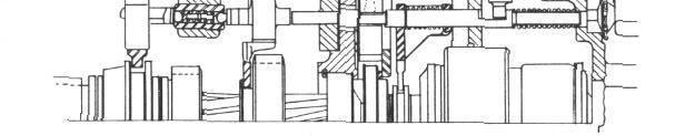
209 OVERDRIVE 9-1
210 9-2 OVERDRIVE FIGURE 2 1. Transmission mainshaft 2. Transmissions mainshaft snap ring 3. Transmission mainshaft bearing 4. Transmission snap ring 5. Bearing oil baffle 6. Overdrive to transmission case gasket 7. Overdrive housing adapter 8. Sun gear plate & balk ring 9. Sun gear plate cover 10. Cover plate snap ring 11. Sun gear snap ring 12. Sun gear 13. Pinion cage assembly 14. Pinion cage retainer clip 15. Cam assembly 16. Cam roller retainer spring 17. Cam roller 18. Cam roller retainer 19. Cam retainer clip 20. Shift rail retractor spring 21. Shift rail 22. Control shaft 23. Control shaft oil seal 24. Control lever 25. Shift rail sleeve spring 26. Shift rail sleeve (Single Lever Type) 27. Shift fork 28. Sun gear shift collar 29. Sun gear pawl 30. Sun gear pawl oil seal.31. Solenoid assembly 32. Overdrive mainshaft ring gear 33. Overdrive mainshaft output shaft 34. Snap ring 36. Overdrive housing gasket 37. Overdrive housing 38. Overdrive housing to adapter bolt 39. Governor switch 40. Lock ring 41. Governor pinion 42. Speedometer drive gear 44. Shaft bearing snap ring 45. Overdrive mainshaft bearing - rear 46. Overdrive mainshaft oil seal 47. Companion flange 48. Mainshaft plain washer 49. Mainshaft lockwasher 50. Mainshaft nut 51. Control switch gasket 52. Control switch 53. Control Shaft Locating Pin 54. Lockup Rail Spring "C" Washer (Double Lever Type) 55. Lockup Rail Spring Plain Washer (Double Lever Type)
211 OVERDRIVE 9-3 NOTE: Unless otherwise designated all instructions and operations are for overdrive transmissions used with either the single lever type or double lever type manual control transmissions. TRANSMISSION OVERDRIVE used, making available the acceleration so desirable at lower speeds. As the car speed increases above the cut-in point the overdrive unit will shift into overdrive ratio, but only when the driver desires no further acceleration; when consciously, or unconsciously, he lifts his foot from the accelerator, whereupon the shift is completed. Thereafter, the overdrive remains in effect until the car speed falls below the "cut-out" points, 16 to 19 mph, when the overdrive is released. However, at high speeds, the driver while operating in overdrive may require additional acceleration beyond that available by opening the throttle wide. His natural impulse is to press the accelerator further, and his act releases the overdrive, making available the full acceleration of direct drive. The direct drive is retained as long as the full acceleration is required; when the driver no longer requires it he lifts his foot from the accelerator, whereupon the overdrive is resumed. If the driver so desires, he may retain the direct drive indefinitely by maintaining a small amount of throttle opening. CITY TRAFFIC DRIVING: FIGURE 3 OPERATION Overdrive provides a driving ratio of engine speed to rear wheel speed that is numerically lower than direct drive. In overdrive the engine revolves 30% slower than in direct gear at the same car speed, resulting in less wear on engine parts as well as greater fuel and oil economy and smoother operation at high speeds. HIGHWAY DRIVING: When the car is operated below a predetermined "cutin" speed, varying from 18 to 21 mph, the direct drive is Much city driving is under conditions which permit speeds of mph, with frequent stops. Many drivers are accustomed to start in second gear under such conditions. With overdrive-equipped cars, the driver may start in second gear, accelerate up to the "cut-in" speed, an, by merely lifting the foot from the accelerator pedal, engage the overdrive-second gear combination, which is approximately the same ratio as the usual third speed. At the first traffic stop, it is merely n e c e s s a r y to release the clutch; the gear shift lever is not touched. Furthermore, if a special burst of acceleration is needed in a tight traffic spot, the full power of second gear may be had by pressing the accelerator to the floor, resuming the overdrivesecond by the usual method of closing the throttle.


212 9-4 OVERDRIVE OPERATION MECHANICAL FREE-WHEELING DIRECT DRIVE mainshaft, pinion cage, and engine turning at a slower speed than the ring gear, output shaft and propeller shaft. Under such conditions The transmission mainshaft, Figures 3 and 4, extends through the sun gear and is spindled into the pinion cage and roller clutch cam. The latter has 12 cam surfaces and 12 clutch rollers located against these surfaces by means of the roller cage and the roller cage spring. FIGURE 5 the ring gear will turn faster than the pinion cage, and the sun gear will turn slower than the latter. In fact, the sun gear may turn forward, stand still, or turn backward, depending solely upon the relative speeds of the transmission main shaft, and the output shaft. If the former is turning at exactly 70% of the FIGURE 4 When a driving torque is applied against the cam, the rollers are forced outward into wedging contact with the outer race, Figure 5-A, thus driving the car. Under such driving conditions, all the overdrive gears and their directlyassociated control parts revolve together as a unit. On the other hand, if the throttle is closed, removing the driving force, the rollers release their wedging contact, Figure 5-B, permitting the roller clutch to overrun, with the FIGURE 6
213 OVERDRIVE 9-5 speed of the latter, the sun gear will stand still; if it turns faster than this, relatively, the sun gear will turn forward; and if it turns slower, the sun gear will turn backward. If the engine is idling with the car moving forward, this reverse rotation may be quite fast. FIGURE 7 OVERDRIVE If the sun gear is held against rotation, Figure 6, the pinion cage, and also the engine, will revolve through only 0.7 turn for each turn of the propeller shaft, Figure 7. The action of the control elements involved is as follows: Assuming that the car is being driven with the dash control pushed in, Figure 4, the sun gear control plate revolves along with the sun gear at the speed of the transmission main-shaft. Under such circumstances, the blocker ring, by its frictional drag upon the hub of the control plate, is rotated into such a position as to latch the control pawl against inward movement, Figure 8-A. When the car reaches a predetermined speed (the "cut-in" speed, which varies between 18 and 21 mph.) the governor contacts close, acting through the overdrive electrical circuit to energize the solenoid. The latter sets up a spring pressure against the pawl, tending to push it into engagement. This movement is prevented by the blocker. However, the driver either consciously, or unconsciously, and according to his own choice, may momentarily close the throttle, whereupon the roller clutch releases, and the engine slows down. At the same time, the sun gear slows down, more rapidly, so that the sun gear passes through the stand-still condition when the engine speed has fallen 30%, and then reverse its motion. Upon the instant of reversal, the blocker ring, moved by its frictional drive from the control plate hub, also rotates slightly in this direction and releases the pawl which snaps into the first notch of the backwardly-rotating control plate, Figure 8-B. The extreme rapidity of this action insures that the control plate cannot rotate backward more than 1/3 turn at the most; usually, it will be less. This engagement, at nearly perfect synchronism, accounts for the smooth action this control. Once engaged, under the conditions of normal driving, the overdrive is in action until the car speed falls to a value 2 or 3 mph lower than the cut-in speed, when the governor contacts open, releasing the solenoid, which withdraws the pawl (if throttle is closed), whereupon the condition of freewheeling direct drive is resumed. DRIVER-CONTROLLED DOWNSHIFT (kickdown) FIGURE 8 It has been noted above that when the overdrive is engaged, the engine only turns 0.7 as fast as when in direct drive. This reduces the power available (excepting at high car speeds) and although this reduced power is usually sufficient for all purposes,there are

214 9-6 OVERDRIVE times when it is desirable to return to direct drive for more power without reducing the car speed to the point where the overdrive would normally release. Under such circumstances, the driver merely presses the accelerator pedal beyond the wide-open position. Through suitable electrical controls, this releases the :solenoid, urging the pawl toward release from the control plate. However, due to the driving torque reaction, the pawl is held, and cannot move to release until the torque is momentarily relieved. This is accomplished by interrupting the ignition, whereupon the pawl snaps to release, which immediately restores the ignition. When the overdrive has been thus disengaged the roller clutch carries the direct drive, and the driver may hold it in this condition at his pleasure, until he chooses to reengage overdrive by merely lifting his foot from the accelerator momentarily. Thereupon the overdrive is resumed, unless the car speed has in the meantime fallen below the overdrive release point. the free-wheeling and the overdrive, there are times as when descending long steep grades, where it may be desirable to use the frictional drag of the engine as a brake. Under such circumstances, the overdrive dash control may be pulled out, swinging the control lever, Figure 9, forward, thus moving the shift rail and shift fork backwards, shifting the sun gear so that the lockup teeth will engage the corresponding teeth of the pinion cage. This causes the entire group of working parts to revolve as a unit, duplicating in all respects the action of the conventional transmission. In order to thus lock up the unit, if the car is in motion, it is necessary to open the throttle, to assure that all parts revolve together, or to release the overdrive, if engaged, by pressing the accelerator pedal to the floor, pulling out the overdrive dash control at the same time. Thereafter, the car will have the usual conventional drive until the driver chooses to push the overdrive dash control in, which may be easily done at any time. Since the roller clutch will not transmit a reverse drive, it is necessary for the lockup mechanism to be used whenever it is desired to reverse shift mechanism, which pushes the shift rail to the rear, independently of the overdrive control lever, whenever the transmission is shifted into reverse. ELECTRICAL While the mechanical structure of the overdrive unit just described, may be considered the working portion of the combination, its automatic action is controlled entirely by the external electrical control system. This system consists of certain units, connected by a wiring circuit. Figure 10. FIGURE 9 CONVENTIONAL DRIVE: Although the normal procedure is to operate that unit as above, taking advantage of SPEED-CONTROLLED OPERATION: At low car speeds, the electrical control system is completely inactive. Whenever the car speed reaches the predetermined cut-in point, (18 to 21 miles per hour) centrifugal force, acting upon the revolving governor weights, is sufficient to cause the governor contacts to close.
215 FIGURE 10 OVERDRIVE 9-7
216 9-8 OVERDRIVE This grounds that portion of the circuit connected to one terminal of the relay (marked 2), and if the generator is charging the relay contacts will close. This sends battery current to the solenoid terminal No. 4 (1/4" terminal screw) energizing the windings of the solenoid, causing the solenoid plunger to move, compressing the inner spring, and urging the pawl toward engagement. Upon completion of the plunger movement, a contact within the solenoid opens, disconnecting the heavy traction-coil winding, leaving the lighter holding-coil winding energized. The solenoid parts remain in this position until the driver closes the throttle, which causes the slowing-down of the sun gear to the reversal point and permits the pawl to move into engagement under the pressure of the inner spring. The movement of the solenoid plunger also compresses the outer spring; whenever the car speed falls to a point 2 or 3 mph. below the cut-in point, the governor contacts open, releasing the relay, and opening the solenoid circuit, whereupon the outer spring withdraws the pawl from engagement. The circuit then remains inactive until the car speed again reaches the cut-in point. DRIVER CONTROLLED OPERATION When operating in overdrive, the driver may require to return to direct drive without reducing the car speed below the cut-out point. If the accelerator pedal is pressed down beyond the position corresponding to wide-open throttle, the stem of the kickdown switch is pressed, thus opening that part of the control circuit between the governor and relay, whose contact points open, de-energizing the solenoid, the outer spring of which urges the pawl toward release. Due to the fact that the engine is driving the car through the overdrive gear train, the pawl is pinched by the torque reaction and cannot release until the driving torque is removed. This is accomplished as follows: The solenoid stem is provided with a contact which closes whenever the pawl is engaged grounding the No screw terminal of the solenoid, which is connected to one of the lower terminals of the kickdown switch; when the latter is moved to open the connection across its upper terminals, the lower terminals are connected, and this grounds the primary breaker of the ignition distributor, thus interrupting the engine torque. The pawl immediately snaps out of engagement, and this movement opens the grounding contacts of the solenoid, restoring the ignition. This entire action occurs with such rapidity that not more than 3 or 4 cylinder explosions are missed. In the event that the driver raises his foot slightly from the accelerator pedal the normal position of the throttle switch is restored, thus re-energizing the solenoid, but the pawl cannot reengage until the throttle is closed to cause the engine to slow down sufficiently to reverse the rotation of the sun gear, as previously explained. LOCKED-OUT OPERATION: When the overdrive unit is operated in the locked-out, or conventional drive condition, either by having the dash control knob pulled out, or by shifting the transmission into reverse, the shift rail is moved to the rear which also opens the control switch. Since this opens the circuit between the governor and relay, the latter cannot act to energize the solenoid. This prevents any possible attempt to engage the pawl when operating in either conventional drive or reverse. OVERDRIVE REPAIR SERVICING EXTERNAL UNITS GOVERNOR SWITCH AND PINION: Servicing of governor switch and governor switch pinion may be accomplished by disconnecting wire or wires at governor switch and then screwing governor switch out of overdrive case.
217 OVERDRIVE 9-9 CONTROL SWITCH The control switch is attached to the Overdrive housing by two screws. Before reinstalling check for damaged gasket and defective wire terminals. SOLENOID Detach the solenoid by removing the two mounting screws and turning solenoid 1/4 turn clockwise while pulling out. To Install, reverse this procedure. After holes in flange and housing are lined up, but before Installing cap screws, pull straight out on solenoid. If it can be pulled out, the ball at the end of the solenoid rod was improperly Installed (not locked in the pawl.) OIL SEAL (OD. MAINSHAFT) 1. Disconnect universal joint at transmission companion flange. 2. Remove the bolts attaching the propeller shaft center bearing support bracket and move propeller shaft rearward to clear companion flange. 3. Remove the companion flange nut, washer, and with puller tool J-820, remove the companion flange. 4. Pry out oil seal from rear of case. NOTE: DO NOT DAMAGE overdrive case bore during this operation. To Install, reverse procedure of removal and coat outside of seal with a film of white lead and drive seal into place with a suitable driver. Tighten companion flange nut to foot pounds. OIL SEAL (OD. CONTROL SHAFT) Remove control lever and pry out seal with sharp punch. Coat outside of new seal with white lead and drive seal into place with a tubular driver having an inside diameter of 5/8" and outside diameter of 15/16" SERVICING UNITS REQUIRING REMOVAL OF OVERDRIVE HOUSING ONLY Repairs to the overdrive case, overdrive mainshaft, mainshaft ring gear, free wheeling cam, pinion cage assembly, stationary gear, shift rail and fork assembly, overdrive mainshaft rear and front bearing, overdrive main-shaft oil seal, speedometer drive gear, solenoid pawl and interlock plunger may be performed underneath the car by removing the overdrive housing without disturbing the transmission. See "Overdrive Housing Removal". However, if the transmission mainshaft, overdrive adapter, or transmission mainshaft bearing are to be replaced, it will be necessary to proceed as outlined under "Transmission and Overdrive Removal". OVERDRIVE HOUSING REMOVAL 1. Place car on stand jacks. 2. Remove drain plugs and drain transmission and overdrive cases. 3. Disconnect governor switch and overdrive solenoid and control switch wires. 4. Disconnect universal joint at overdrive companion flange. 5. Remove the bolts attaching center bearing support bracket and move propeller shaft rearward to clear companion flange. 6. Remove speedometer cable and speedometer driven gear. 7. Disconnect overdrive control cable at control shaft lever. 8. Remove the companion flange nut, washer and with puller J-820, remove the companion flange.

. FIGURE 13 3.")

218 9-10 OVERDRIVE FIGURE 11 FIGURE Remove the overdrive mainshaft and ring gear assembly, Figure 12, (Catch the rollers as they drop out of the free wheeling cam roller retainer.) 9. Drive out the overdrive control shaft tapered pin, Figure 11, and pull control shaft out as far as possible to disengage the operating cam of the shift shaft from the slot in shift rail. NOTE: Small end of taper pin is down. 10. Remove the four bolts attaching the overdrive housing to transmission and overdrive adapter. 11. Remove overdrive housing. (Lightly tap the end of the overdrive mainshaft with a rawhide mallet to prevent mainshaft from coming off with the overdrive housing and spilling the free wheeling rollers). FIGURE Removing lock ring (2), Figure 13, will permit the removal of the ring gear (1) from the overdrive mainshaft (3), the oil collector ring (4) is spun securely to the mainshaft to form an oil tight seal. NOTE: Removal of the overdrive housing will expose the overdrive mainshaft and ring gear, free wheeling cam, pinion and cage assembly, shift rail and fork, stationary gear, stationary gear cover plate and overdrive mainshaft bearing REMOVAL OF PARTS FROM REAR OF ADAPTER 1. Install one bolt removed from housing to hold the adapter plate to the transmission case. FIGURE 14


219 OVERDRIVE Remove the retaining clip at the end of the clutch cam, Figure 14, this will allow removal of the cam and the pinion cage assembly. 7, Remove the solenoid attaching screws, turn the solenoid one-quarter turn clock-wise and remove, Figure 17. FIGURE Remove the "U" clip located between the free wheeling cam and pinion cage and separate these units, Figure 15. FIGURE Remove the large snap ring at the adapter plate, Figure 18. FIGURE Remove the sun gear and shift rail assembly, Figure 16. FIGURE The retainer plate, the sun gear, control plate and blocker assembly, and the pawl can then be removed, Figure The interlock lock plunger can be removed by lifting out the plug at the adapter with a sharp punch. Remove interlock by pushing it through the opening uncovered by the plug. Use a stiff wire and work through the opening uncovered by the solenoid. FIGURE 17
220 9-12 OVERDRIVE DISASSEMBLY OF HOUSING 2. Remove the overdrive mainshaft oil seal (46) with Remover J Remove the two bearing snap rings (44) and remove overdrive mainshaft rear bearing (45). CLEANING AND INSPECTION As each part is removed from the assembly, wash it with clean solvent and wipe dry. Protect parts from subsequent dirt accumulation. After cleaning give parts visual inspection for wear or damage. Replace any broken or excessively worn parts. Roller clutch parts should be carefully inspected. If rollers show surface markings of any kind they should be replaced. If inner surface of the outer roll shows slight lengthwise indentations, they are normal and do not impair the action of the clutch. However, if the 12 flat surfaces of the cam show such markings, it should be replaced. Inspect fit and tension of the balk ring on hub as follows: (a) When pushing one end of balk ring away from opposite end, ring should slide around the hub. (b) Push one end toward the other, the balk ring should grab and hold to the hub. If the ring does not hold, it should be replaced. Test the tension of the cam retaining springs after the cam assembly has been thoroughly washed. The springs are designed to twist the cam in a clockwise direction to hold the rollers up on the cam. NOTE: If the spring tension is weak or retarded, the unit will free-wheel at all times. To check spring tension, hold hub of cam and turn roller retainer counter-clockwise; suddenly releasing the retainer should cause the retainer to spring back quickly. If the action is slow or retarded, replace springs or complete assembly. BEARINGS: DO NOT place bearings where dirt is liable to mix with the lubricant in the bearings. Bearings should be washed in clean gasoline or kerosene. DO NOT SPIN the bearings and particularly do not spin bearings with an air hose. Spinning a bearing at high speeds will almost certainly do considerable damage. After washing the bearings, blow them out with clean dry air. Direct the flow of air into the open face of the bearing while holding the inner race and slowly rotate the outer race by hand. DO NOT ALLOW the air to spin the bearing. (a) Inspect the bearing for cracks and defects. (b) Lubricate the bearing with clean, new engine oil, rotating the bearings by hand in order to spread the lubricant over all surfaces. Transmission mainshaft be a rings are built originally with end play and although they may feel quite loose, it does not necessarily indicate that they are worn and unfit for use. GEARS: Inspect all gears for damaged teeth. Remove any and all raised edges from tooth surfaces by hand stoning. Pitted and worn gears should be replaced. CONTROL SHAFT AND SEAL: Recommended clearance between control shaft and overdrive housing bore is.001" to.003" but clearance of twice this amount if not accompanied by oil leakage is permissible. If a new control shaft seal is Installed make sure that it does not interfere with rotation of control shaft. OVERDRIVE MAINSHAFT OIL SEAL: If the seal is hard, cracked, or glazed, or if signs of oil leakage are apparent at disassembly, Install a new seal. OVERDRIVE SHIFT RAIL DISASSEMBLY: (Single Lever Type) Drive out shift rail pin (2), Figure 20, remove sleeve (1), spring (3) and shifter fork (4). Check weight of shift rail springs. The shift rail sleeve spring (3) should have a free length of 2-7/32" and 1-25/64" length under load of eight pounds. The retractor spring in housing has a free length of 2-3/4" and 1-21/32" under load of 12 pounds.


221 OVERDRIVE 9-13 Installation OF ADAPTOR PLATE, SOLENOID PAWL, SUN GEAR CONTROL PLATE AND BLOCKER, SOLENOID, SUN GEAR SHIFT RAIL AND FORK (Single Lever Type) 1. Position the adaptor p late and fasten the adaptor to the transmission case and Install the solenoid pawl, sun gear control plate and blocker assembly, Figure 21. FIGURE 20 DISASSEMBLY - (Double Lever Type) 1. Compress the lockup rail spring, pressing it away from the "C " washer (54) Figure 1 and remove the "C " washer. 2. Pull the shift rail shaft out of the shift fork and remove the spring and plain washer. NOTE: The retractor spring should have a free length of 2-3/4" and 1-21/32" under load of 12 lbs. The lockup rail spring has a free length of 1-3/8" and 15/16" under load of 8 lbs. FIGURE 21 NOTE: Insert the pawl with the notched side up, be sure that the blocker ring and pawl are properly positioned before Installing the snap ring, Figure 22. With pawl fully engaged in slot in stationary gear and one end of the interlock plunger contacting the shift rail REASSEMBLY OF OVERDRIVE HOUSING 1. Install overdrive mainshaft rear bearing rear lock ring (44) Figure 2, rear bearing (45), and rear bearing front lock ring (44). 2. Install new oil seal (46) in overdrive case (37). 3. Before Installing shift shaft (22) in the overdrive housing, coat the shift shaft oil seal counter-bore with white lead and tap in a new oil seal (23). Dip the threaded end of the shift shaft in liquid soap, and using care, push the shaft through the new seal, turn the shaft so that the shifter lug will be in an upright position. FIGURE 22
 Figure 18.")


222 9-14 OVERDRIVE (NOT THE SLEEVE) there should be.008" to.021" clearance between the lower end of the interlock plunger and the side of the pawl. The interlock plunger is furnished in six different lengths, select a plunger of proper length to give proper clearance. 2. Install the adaptor lock ring (large) Figure 18. NOTE: The adaptor lock rings are furnished in three thicknesses:.0625",.0665" and.0705", select the size required to obtain a tight fit in groove in the overdrive adaptor. 3. Install the solenoid by turning the solenoid counter-clockwise one quarter turn, Figure 17, but before Installing the cap screws, pull straight out on solenoid. If solenoid can be pulled out, the bolt at the end of the solenoid rod was improperly Installed (not locked in the pawl). Install lock washers and cap screws and tighten securely. 4. Install the locking rail spring, "C " washer and plain washer on the shift rail and fork assembly. 5. Install the fork in the sun gear shift collar, and while holding the shift fork, shift rail and sun gear together, slide the sun gear onto the main shaft and the shifter rod into the hole in the overdrive adaptor. Installation OF CLUTCH CAM. PINION CAGE AND OVERDRIVE MAINSHAFT 1. Install the clutch cam and pinion cage, attach the clutch cam to the pinion cage assembly with the large retaining clip Figure Install the sun gear, shift rail and fork assembly, Figure 16. Check position of shift rail slots at assembly as shown in Figure 20. THIS IS IMPORTANT. NOTE: If the shift rail assembly has been disassembled, prick punch pin (2), Figure 20, securely in place before reinstalling assembly. Shifter fork should be a sliding fit in the sun gear collar groove. Installation OF ADAPTOR PLATE. SOLENOID PAWL, SUN GEAR CONTROL PLATE AND BLOCKER. SOLENOID. SUN GEAR SHIFT RAIL AND FORK FIGURE Install the pinion cage and the clutch cam assembly on the main shaft and secure the assembly in place with the retaining clip, Figure 24. (Double Lever Type) 1. Install the adaptor plate and use one of the overdrive housing attaching screws to hold the adaptor in position. Install the solenoid pawl, sun gear control plate and blocker assembly, Figure Install the adaptor lock ring (large), Figure Install the solenoid by turning the solenoid counter-clockwise one quarter turn, Figure 17, and before Installing the cap screws pull straight out on solenoid. If the solenoid can be pulled out, the ball at the end of the solenoid rod was improperly Installed (not locked in the pawl). FIGURE 24 NOTE: Replace any "U" clips that are worn or damaged.
223 OVERDRIVE Install the ring gear (1), Figure 13 on the overdrive mainshaft (3) and lock it in place with the large snap ring (2). NOTE: To facilitate Installation of the main-shaft (output shaft) on the free wheeling cam rollers, insert the free wheeling rollers in the cam roller retainer cage, using heavy grease to hold them in position. Then, with the low gear of the transmission engaged, turn the cage and rollers counter-clockwise until the rollers are in their low positions, and snap a tight fitting rubber band around them. Install the output shaft and ring gear on the pinion cage and free wheeling clutch cam and roller unit assembly, turning the shaft to the left as it assembles over the clutch rollers Figure 25. Insert J-4149 O.D. Aligning Pilot in lower right hand hole of adaptor and housing while tightening the other three Overdrive to transmission case bolts. Tighten all 4 bolts to ft. lbs. torque. 6. Install control shaft locating pin, large end up. 7. Install control switch, governor pinion, and governor switch. 8. Install companion flange, washer, and nut. Tighten nut to lbs. torque. 9. Add lubricant to get proper level in both transmission and O.D. units. SERVICING UNITS THAT REQUIRE REMOVAL OF COMPLETE ASSEMBLY REMOVAL: (Single Lever Type ) 1. Remove front seat cushion. 2. Remove the four bolts attaching the bottom of front seat frame to seat track. Remove two screws attaching seat adjusting lever to seat frame and remove seat back from car. FIGURE 25 OVERDRIVE HOUSING Installation 1. Remove bolt holding adaptor to transmission case. 2. Install overdrive to adaptor gasket. 3. Install overdrive case. 4. With the control switch removed, insert a long thin drift through the housing at the control switch opening to line up the retractor spring and the overdrive shift rail. 5. While case is being Installed, push the control shaft inward and engage the slot in the shift rail with the shifter shaft lug. ( Lug must be up and outside control lever down.) 3. Disconnect accelerator pedal at accelerator rod. 4. Remove foot brake pedal rod from brake lever. 5. Pull the steering column hole rubber grommet up out of the way. 6. Remove the floor mat. 7. Remove Hudson Weather Control b1ower unit held by four screws, (2 each side). Disconnect cable at Ranco weather control valve. 8. Disconnect plug at overdrive kickdown switch. 9. Release speedometer cable from clip on under side of floor opening cover.
224 9-16 OVERDRIVE 10. Remove the floor opening cover over the transmission. 11. Raise car, place on stand jacks. 12. Drain transmission and overdrive units. 13.Disconnect wires at governor switch, solenoid, and overdrive control switch (located at left rear side of overdrive case). 14. Disconnect speedometer cable and remove speedometer driven gear. 15. Disconnect overdrive control cable from overdrive shift shaft lever. 16. Disconnect the front universal joint at transmission. Remove bolts attaching center bearing support bracket and move propeller shaft rearward to clear transmission companion flange. NOTE: Use a wire or rubber band to prevent the trunnions from slipping off the "U" joint journal. 17. Disconnect the clutch pedal lever return spring. 18. Remove the two clutch cross shaft bracket bolts and remove clutch cross shaft bracket. 19. Remove the clutch control link clevis pin and unhook clevis. 20. Remove shifter shaft outer lever, nut and washer. This will disconnect the linkage connecting the gear shift to the transmission. 21. Remove two screws and remove flywheel guard from bottom of clutch housing. 22. Remove the two engine rear mounting bolts. 23. Jack up rear end of engine about 1/2" off the frame. CAUTION: Place a block of wood under head of jack to prevent damage to oil pan. 24. Remove the two top screws holding clutch housing to engine end plate and Install two J-2969 headless screws or studs to support the transmission until the balance of the screws are removed. 25. Remove breather pipe bracket from clutch housing and bolt attaching breather pipe and rear tappet cover. 26. Remove the nut from brake control hand brake cable lever pivot plate brace and remove bolt and nut attaching hand brake cable lever to cable lever pivot plate side'; brace. This will allow the hand brake control levers to be pushed out of the way to facilitate removal of the overdrive and transmission. 27. With a helper pull transmission and clutch housing back towards the rear and down, removing the unit from underneath the car. NOTE: For removal of parts from rear of adaptor, see instructions on page NOTE: For disassembly of housing, see instructions on page REMOVAL: (Double Lever Type) 1. Remove drain plugs and drain lubricant. 2. Loosen the propeller shaft center bearing support bolt. 3. Remove the nuts, washers and clamps from the front universal joint and disconnect the propeller shaft at the front companion flange by sliding the shaft rearward. 4. Use a rubber band or tape to hold bearing cups and needle rollers in place. 5. Disconnect the low and reverse and the high and intermediate shift rods at the transmission shifter levers. 6. Disconnect the speedometer cable at transmission and the governor wire at the overdrive control switch 7. Disconnect the overdrive control cable from the overdrive shift shaft lever.

225 OVERDRIVE Remove the governor and governor driven gear and the speedometer driven gear. 9. Remove the nut from the front end of the brake pivot brace at the No.3 cross-member. 10. Remove the clevis pin at the rear end of the brake pivot brace. This will allow moving the linkage to the left side of car and give additional clearance when lowering and removing the transmission with overdrive. NOTE: Some of the bearing rollers may fall into transmission case at this time. 7. Remove mainshaft lock ring with Lock Ring Pliers KMO Remove the synchronizer shift sleeve and hub assembly, intermediate gear, low and reverse gear through cover opening in transmission and pull out mainshaft with overdrive housing adaptor. 9. Remove the mainshaft rear bearing snap ring, Figure Using a universal socket on a 10" extension, remove the top bolts attaching the transmission case to clutch housing. Install two I-2969 Guide Studs to support transmission when removing the two lower bolts. 12. Remove the transmission and overdrive assembly, using care not to damage the main drive gear splines and pilot during removal. DISASSEMBLY - COMPLETE UNIT (Single Lever Type) 1. Remove six bolts attaching clutch housing to transmission case and remove clutch housing. 2. Install transmission on bench holding fixture and remove transmission cover, gasket, shift rail ball spring and ball. 3. Remove low and reverse shifter fork lock screws. NOTE: To remove these special self-locking screws, use a screwdriver having a straight blade that will enter to the bottom of screw slot. DO NOT USE A TAPERED BLADE SCREW DRIVER. 4. Slide low and reverse shift rail out of front of case, then remove shift fork and shifter, also the shift rail interlock. 5. Remove the set screw from the second and high shift fork and the shift rail stop screw, then slide the shift rail out of front of case. Remove the lock ball and spring from case. 6. Pull mainshaft rearward and main drive gear forward until mainshaft is fully withdrawn from needle roller pilot bearing in rear end of main drive gear. FIGURE Remove transmission mainshaft rear bearing and oil baffle from adaptor. NOTE: For inspection procedure, see instruction on page DISASSEMBLY - COMPLETE UNIT (Double Lever Type) 1. Install transmission on bench holding fixture and remove the transmission cover and gasket. 2. Remove the two screws and washers and remove the overdrive control switch and gasket. 3. Remove the companion flange nut, lock- washer and plain washer and using Companion Flange Puller.T-820, remove the companion flange. 4. Drive out the overdrive control shaft tapered pin, Figure 11 and pull the control shaft outward approximately 3/8" to disengage the operating cam of the shift shaft from the slot in the rail.
226 9-18 OVERDRIVE 5. Remove the four bolts attaching the overdrive housing to transmission and overdrive adaptor. 6. Slide the overdrive housing rearward carefully. Lightly tap the end of the overdrive mainshaft with a rawhide mallet to prevent the mainshaft from coming off with the overdrive housing and spilling the free wheeling rollers. 7. After the overdrive housing is removed, perform operations 1 thru 10 under "Removal of Parts From Rear of Adaptor", Page 10, also "Disassembly of Housing", Page 12, "Cleaning and Inspection", Page 12, "Bearings", Page 12, "Gears, Control Shaft and Seal, Overdrive Mainshaft Oil Seal and Overdrive Shift Rail", Page 12. NOTE: The countershaft and idler gear shaft lock plate cannot be removed without removing the overdrive adaptor. To remove the adaptor it is necessary to remove the main drive gear bearing in order to remove the mainshaft and adaptor without lowering the cluster gear assembly. 8. Drive the main drive gear bearing loose from the case sufficiently to use a puller on the bearing snap ring and pull the bearing from the main drive gear and transmission case. 9. Remove the bolt from the adaptor plate and tip the mainshaft upward and to the right to remove the second and high shift fork and the low and reverse shift shoe. 10. Remove the complete transmission main-shaft assembly with the overdrive adaptor from the transmission case as an assembly. 11. Remove the main shaft lock ring from front end of mainshaft. NOTE: With a small, pointed, brush, paint a fine line across the synchronizer rings, sleeve and the second and high gears to facilitate proper assembly of these parts in reassembly. 12. Remove the synchronizer shift sleeve and hub assembly, intermediate gear and low and reverse gear from mainshaft. 13. Remove the large snap ring from the adaptor plate at the mainshaft rear bearing and pull the adaptor plate off the bearing. 14. Remove the oil slinger from the adaptor plate. 15. Remove the small snap ring and using a suitable arbor press, remove the rear bearing from the mainshaft. 16. Using a brass drift, move the countershaft rearward just enough to free up the lock plate in the shaft groove at the rear end. 17. Make a dummy steel countershaft, 3/4" diameter exactly 7-5/64" long with a 3/16" hole drilled 1" deep at each end. The purpose of the dummy shaft is to retain the needle rollers, sleeve and thrust washers in position when removing or Installing the countershaft gear cluster. 18. Place end of dummy shaft against the front end of the countershaft, carefully drive the countershaft rearward out of the transmission case. CAUTION: Be sure the dummy shaft remains in constant contact with the countershaft during this operation otherwise the thrust washers, needle rollers and spacer with fall out of place. 19. Use a long brass drift and drive the reverse idler gear shaft out of rear of transmission case and remove the idler gear. 20. With dummy shaft holding needle rollers and thrust washers in position, lift countershaft gear cluster straight up and out of transmission case. NOTE: Remove the thrust washers noting position to insure exact replacement. 21. Drive out taper pins securing the transmission shift shafts (small end of taper pin is down). 22. Remove nuts, washers and levers from shift shafts and take shafts out of case. When doing this, also remove the interlock sleeve, detent balls, spring and pin, Figure 27.
227 OVERDRIVE Install synchronizer shift sleeve hub lock ring on end of mainshaft using lock ring pliers. 9. Apply a coating of viscous grease td mainshaft pilot bearing recess end of main drive gear. Insert the sixteen individual rollers comprising the pilot bearing. 10. Engage front end of mainshaft in pocket of main drive gear and press firmly in place. NOTE: Do not hammer on end of mainshaft. 11. Place one bolt to hold adaptor to transmission case while performing balance of assembly. FIGURE 27 REASSEMBLY COMPLETE UNIT (Single Lever Type) 1. Thoroughly clean both transmission and overdrive cases. 2. Install transmission mainshaft bearing and oil baffle (lip to inside) on mainshaft and in overdrive adaptor. 3. Install bearing lock ring in adaptor. 4. Install new overdrive adaptor to transmission case gasket. 5. Install transmission mainshaft part way in transmission case and Install low and reverse gear with shifter fork groove toward front of shaft. CAUTION: It is important that the f our oil holes be lined up with the grooves in main-shaft. NOTE: The transmission mainshaft and transmission gears are a select fit. If it is ever necessary to replace a transmission mainshaft or a complete overdrive assembly, the fit between the involute splines of the mainshaft and splines in the gears should be free from any binding. In the event binding exists, it may be necessary to stone the splines of the mainshaft to obtain proper clearance. 6. Slide the intermediate gear on mainshaft with the tapered side of the hub toward the front of the mainshaft. 7. Install synchronizer shift sleeve assembly and two bronze synchronizer rings on the mainshaft with the tapered end of the shift sleeve toward the front of the mainshaft. 12. Install second and high shift rail lock ball and spring in transmission case. NOTE: Light spring for high and second shift rail. Heavy spring for low and reverse shift rail. 13. Place second and high shift fork in position in synchronizer shift sleeve groove and Install shift rail and set screw. 14. Install shift rail stop screw. 15. Install shift rail interlock. 16. Place low and reverse shifter in position behind shift shaft inner lever. 17. Place low and reverse shift fork in position, Install shift rail and shift fork and shifter set screw. Install parts per "Installation of Parts To Rear of Adaptor." Pages 13 and 14. Reassemble and Install housing per "Reassembly of Housing" and" Installation of Housing." Pages 13 and 15. INSPECTION: NOTE: For inspection procedure, see instructions on Page 12.
 on mainshaft and in the overdrive adaptor. Retain the assembly in position with the large snap ring. 3.")
228 9-20 OVERDRIVE REASSEMBLY - COMPLETE UNIT (Double Lever Type) 1. Thoroughly clean both the transmission and overdrive cases. 2. Install the transmission mainshaft bearing and oil slinger (lip to inside) on mainshaft and in the overdrive adaptor. Retain the assembly in position with the large snap ring. 3. Install new shift shaft oil seals. The oil seals can be driven out from the inside of transmission c a se with a punch and tapping the new seals in place from the outside of case. NOTE: When Installing oil seals, coat outside of seal and inside of housing with red or white lead or gasket sealer to insure leak-tight joints. 4. Install the low and reverse shift shaft in the transmission case. DO NOT damage the oil seal. 5. Insert interlock sleeve in the transmission case and Install the interlock spring, interlock pin and one interlock ball. Align the neutral detent of the low and reverse shift shaft cam with the interlock ball and while holding the low and reverse shift shaft in position, Install the tapered pin in the case. 6. Install the second and high shift shaft in the transmission case, pushing the shaft in as far as possible. Install the other interlock ball by inserting it over the interlock spring, compressing the spring and at the same time s lid in g the second. and high shift shaft toward the center of the case to its correct position. 7. Install shift shift levers, short (low and reverse) on rear shaft and long (second and high) on front shaft. Move either lever into any in-gear position and with one end of the interlock sleeve contacting a shift shaft cam, measure the clearance with a feeler gauge between the opposite end of the sleeve and the c am of the other shift shaft, Figure 28. This clearance should be from.001" to.007". If not within these limits, remove sleeve and replace with one of proper length. Interlock sleeves are available in five different lengths as shown in specifications. Install taper pin retaining second and high shift shaft in case. FIGURE To Install countershaft gear cluster assembly, place needle roller spacer tube over dummy shaft and insert in cluster. Apply viscous grease between shaft and inside of gear at each end and place needle roller washers in position against each end of spacer tube. Next, insert needle rollers (22) between inside of gear and dummy shaft, followed by a retaining washer at each end. 9. Coat countershaft thrust washers and ends of cluster with viscous grease and place washers in position. Install front washer with bronze face to gear and lug at top. The rear inner (bronze) thrust washer should be Installed so the lugs will engage the slots in the cluster gear and the outer (steel) thrust washer with the lug at top. 10. Carefully lower cluster and assembled parts into position and enter front end of countershaft at rear of transmission case, tapping it forward while holding the front end of the dummy shaft in constant contact with the countershaft to keep needle rollers and washers in place. Drive countershaft forward just far enough to enter front end in case, as it must again be removed after checking end play. 11. With a feeler gauge inserted between the rear thrust washers, check countershaft cluster end play, Figure 29. End play should range between.006" and.016"; if more than this, the thrust washers should be replaced.

229 OVERDRIVE 9-21 NOTE: Assemble synchronizer hub, shift plates, shift sleeve, springs and synchronizer rings together as a unit and slide on main-shaft splines with the long hub of the sleeve pointing forward. Be sure that marks painted on parts during disassembly are in proper alignment, also that the hooked ends of the two synchronizer springs engage in the same shift plate. 19. Install snap ring on front of mainshaft and check end play by inserting a feeler gauge between the rear face of the main-shaft second speed gear and the front ends of the mainshaft spiral splines. This should be from.003" to.016". Excessive end play at this point can only be corrected by Installing new parts. FIGURE Next enter dummy shaft in front of case and by tapping on shaft with a soft hammer, drive out countershaft through rear of case, using care to keep ends of shafts together at all times. Lower countershaft cluster with dummy shaft in place, to bottom of case. 13. Place reverse idler gear in position in case (long hub toward front) and drive idler gear shaft in from rear of case. Before fully Installing shaft, make sure slot for lock plate is properly aligned with countershaft so plate will seat in both slots. Idler gear end play should be from.003" to.010". 14. To Install countershaft, insert two suitable punches through countershaft holes in front and rear of transmission case, entering the punches in the 3/16" holes drilled in the ends of the dummy countershaft. With punches, raise the countershaft cluster until in alignment with countershaft holes in case, then insert countershaft through hole in rear of case. 15. Tap rear end of countershaft moving it forward and pushing dummy shaft out through front of case. When doing this, keep dummy and countershaft in contact with each other and line up slot in rear end of countershaft for lock plate. 16. Place lock plate in correct position engaging slots at ends of countershaft and reverse idler shafts and tap both shafts until lock plate is tightly held. 17. Install the low and reverse sliding gear. 18. Install the second speed and synchronizer gear. 20. Install the main shaft assembly and adaptor plate in the transmission case. 21. Install low and reverse fork in rear shift lever shaft (offset to front) and engage fork in groove of low sliding gear. 22. Install second and high shift fork in second and high shift shaft, move mainshaft and parts toward shift fork and engage fork in groove of synchronizer shift sleeve. 23. Complete Installation of mainshaft and rear bearing in case by tapping rear bearing outer race with plastic or rawhide hammer until bearing case snap ring is flush with rear of case. 24. Coat inside of mainshaft drive gear and mainshaft front rollers with lubriplate or heavy viscous grease and assembly rollers (14) in position in gear. 25. Install mainshaft drive gear assembly tapping outer race of bearing with a plastic or rawhide hammer until snap ring in outer race is flush with front of case. When doing this be sure rollers are not dislodged before pilot end of mainshaft enters drive gear. 26. Tap front face of drive gear bearing outer race to make sure it is fully in place. 27. Install main drive gear bearing retainer with new oil seal Installed and without gasket and without screws. 28. With a feeler gauge, check clearance between rear face of retainer and front of transmission.
230 9-22 OVERDRIVE 29. Remove retainer and select and Install a gasket.003" to.005" thicker than clearance indicated by feeler. (Gaskets are available in four different thicknesses.) 30. Place bearing retainer in position, Install 3 cap screws and tighten, making sure oil drain hole in flange is aligned with hole in case. 31. Install the transmission cover and gasket. The cover gasket has three vent holes and must be Installed with holes to rear of case. The cover has one vent hole and is Installed with hole to front of transmission. See marking on cover. 32. Complete balance of assembly as outlined under "Installation of Adaptor Plate, Solenoid Pawl, Sun Gear Control Plate and Blocker Solenoid, Sun Gear, Shift Rail and Fork, Clutch Cam, Pinion Cage and Overdrive Mainshaft", Pages 13 and 14, also " Overdrive Housing Installation", Page 15. TRANSMISSION AND OVERDRIVE Installation 1. Install two headless screws or studs in engine end plate to assist in supporting the overdrive and transmission at Installation. NOTE: Before Installing the overdrive and transmission to engine rear support plate, check cylinder block rear support plate very carefully for tightness and alignment. This is especially important in cases where the car has been subject to chronic transmission trouble, noisy and jumping out of gear. Make a similar check of transmission clutch bell housing. In lieu of highly precise equipment, use a steel straightedge to check steel rear support plate and a surface plate or other flat surface to check the front face of clutch bell housing. Both units should be flat and in plane within.005". Be sure to check position of clutch driving plate and see that it is perfectly centralized within the clutch assembly. This can be done by using the J-449 aligning arbor or with a standard main drive gear if arbor is not available. If this precaution is not taken, difficulty will be encountered when Installing the transmission and the front end of the drive gear shaft and pilot bearing in the flywheel will be damaged. 2. Rotate clutch collar and throwout bearing to position for proper alignment with throwout yoke on transmission. 3. Tighten all rear engine support plate to block screws. 4. Bring the overdrive and transmission assembly to position where the main drive gear (clutch shaft) is aligned with bore of clutch throwout collar, then carefully push transmission forward to enter drive gear splined shaft through grease retainer leather washer, splines of clutch driving plate and into pilot bearing in flywheel. NOTE: During this operation the main drive gear must be relieved of all over hanging weight of the transmission until the bell housing engages the dowels on engine rear support plate. Before transmission assembly is moved up against rear support plate make a last inspection to verify that end face of throwout collar in clutch is properly aligned with throwout yoke on transmission and that oil seal lip has not turned under. CAUTION: Alignment of bell housing with engine is controlled by the sleeve dowel in the upper left location of tile bell housing attaching bolt circle and by the dowel bolt at the lower right location viewed from rear of car. Make sure that the former is in place and entered in bell housing hole before tightening bolts. Install lower right bolt (dowel bolt) first. NEVER grind or otherwise reduce the diameter of the dowel bolt to facilitate Installation. 5. Remove the two headless screws or guide studs, J Install remaining clutch bell housing bolts and screws and tighten with a torque wrench to foot pounds. 7. Complete remainder of Installation by reversing the order of removal of the remaining parts. Check adjustments and refill transmission and overdrive. A total of 3-1/4 pounds of lubricant is required for the single lever type transmission and 3 pounds for the double lever type transmission.


231 OVERDRIVE 9-23 UNIT CHECKS OVERDRIVE RELAY CHECK: Disconnect plug at relay and Install test harness to overdrive relay, but do not connect test harness to overdrive harness plug. A jumper wire must be connected between No. 3 pin and negative terminal of battery at all times during check 1. Connect test lamp successively between a ground and Nos. 1 and 4 contact pins. The test lamp should not light on either of these checks. Connect No. 1 to No. 3 (pin) and a test lamp between No. 4 and a ground. Relay should click and test lamp should light when No. 2 pin is grounded. C. IGNITION GROUNDING CONTACT - Place a test lamp between negative battery terminal and solenoid terminal No. 6. Lamp should light when this connection is made. Remove jumper from between negative battery terminal and solenoid terminal No. 4. Pawl rod should snap "in" and test lamp should go out. GOVERNOR CHECK: FIGURE 31 FIGURE 30 If relay clicks and test lamp does not light, check fuse and fuse holder. SOLENOID CHECK: A. CLOSING COIL - Remove solenoid from transmission, connect a jumper wire between positive t e r m i n al of battery and mounting flange of solenoid. Connect a second jumper wire between the battery negative terminal and solenoid terminal No. 4; this should cause the solenoid pawl rod to move out. If solenoid chatters in Check A, Hold-In Coil is defective. B. ENGAGING SPRING - With jumper wire still connected as in paragraph "A", (solenoid energized, plunger extended) place ball end of solenoid against bench. Push down on solenoid. The pawl rod should move in 3/8" under a load of not less than 8 lbs. nor more than 12. Pawl should move out to extended position when load is removed. Remove overdrive wire at governor and connect test lamp between governor overdrive terminal and negative terminal of battery Figure 31. Drive car on road or raise on jacks. The lamp should light at a car speed of between 18.5 to 21 M.P.H. Upon decreasing speed, the lamp should go out at between 18.5 and 16 M.P.H. Differential between light "on" and light "off" should be 2 or 3 M.P.H. car speed. FIGURE 32

232 9-24 OVERDRIVE CONNECTOR PLUG CHECK: Insert a blade 1/4" wide and 1/32" thick successively into each socket of plug for a distance of 1/2". Socket should grip blade tightly enough to make a good electrical contact. NOTE: Flutes on side of plug indicate the plug numbers for example 1 flute or notch is for the No. 1 terminal, 2 flutes No. 2 terminal etc. FIGURE 34 CONTROL SWITCH CHECK : FIGURE 33 kickdown SWITCH CHECK : Disconnect plug at kickdown switch and Install test harness to kickdown switch but do not connect test harness to overdrive harness. A. Connect test lamp between No. 1 terminal and negative terminal of battery; with switch in normal position, lamp should light when No. 4 is grounded but should not light when No. 2, No. 3 or switch case is grounded. B. Connect test lamp between No. 2 terminal and negative to r m in al of battery; with switch stem pushed in, lamp should light when No. 3 is grounded, but should not light when No. 1, No. 4 or switch case is grounded. NOTE: All models with overdrive have a kickdown switch mounted in the floor under the accelerator pedal. The accelerator pedal rod on these cars should be adjusted so that the carburetor throttle is wide open just before the accelerator pedal touches the moveable stem of the kickdown switch. Remove overdrive wires at switch terminals. Ground one switch terminal; connect a test lamp between the other switch terminal and the battery negative terminal Figure 34. Put transmission in neutral. Lamp should light when the overdrive control button is pushed in and should go out when the control button is pulled out. If switch is tested after removal from car, lamp should light when switch plunger is "out" and should not light when plunger is "in". HARNESS CHECK : 1. Remove overdrive harness plug at the overdrive relay and connect test harness to overdrive harness but not to overdrive relay. Disconnect harness plug at kickdown switch. 2. Connect test lamp between test harness lead No. 1 and ground. Lamp should light. 3. Connect test lamp between test harness leads No. 1 and No. 3. Lamp should light with engine not running but should go out when engine is started. Shut off engine after this test.
233 OVERDRIVE Connect test lamp between test harness leads No. 1 and No. 4. Disconnect overdrive black wire at solenoid terminal No. 4. Lamp should light only when this black wire is grounded. 5. Connect test lamp between test harness leads No. 1 and No. 2. Lamp should light when kickdown switch plug socket No. 4 is grounded but not before. To ground this plug socket use a second test harness or a suitable jumper wire. 6. Connect test harness to kickdown switch harness plug but not to kickdown switch put transmission in neutral and push overdrive control button "in". Connect test lamp between negative battery terminal and No. 1 test harness lead. Remove red overdrive wire at governor switch. Lamp should light when the wire is grounded but not before. If the harness does not meet this test the overdrive control switch may be at fault. Disconnect the two wires at the control switch, join them with a connector, and repeat test. 7. Connect test lamp between negative battery terminal and No. 2 test harness lead. Also connect a jumper wire to negative battery terminal. Touch other end of jumper wire to terminal of starter solenoid. Lamp should flash on and off in time with distributor contacts. 8. Connect test lamp between negative battery terminal and test harness lead No. 3. Lamp should light only when overdrive green wire from solenoid terminal No. 6 is grounded. TROUBLE SHOOTING MECHANICAL CONDITION NO. 1 DASH CONTROL IMPROPERLY CONNECTED: A. Unless the overdrive dash control wire is connected to the control lever on the left side of the overdrive housing in such a manner as to move the lever all the way back when the dash control knob is pushed in, the lockup switch may be held open, thus disabling electrical control operation. Likewise, it may hold the shift rail in such a position as to interlock the pawl against full engagement, even though the control switch is not held open, resulting in a buzzing noise when overdrive engagement is attempted. B. To correctly make this connection, loosen binding post at lever, pull dash control knob out 3/64", move lever all the way to the rear, and tighten binding post. CONDITION NO. 2 TRANSMISSION AND OVERDRIVE IMPROPERLY ALIGNED: A. The same symptoms as above may also result from misalignment at assembly of the overdrive housing to the transmission case, resulting in binding of the overdrive shift rail, so that the retractor spring cannot move the rail fully forward, when the dash control knob is pushed in, and the transmission is not in reverse. Under such conditions, the unit may remain fully locked up. B. To test for this, be sure that the transmission is not in reverse; disconnect the dash control wire from the lockup lever, and feel the lever for free forward movement. If the lever can be moved forward more than 1/4 inch, it indicates that misalignment probably exists. To correct this, loosen the 4 cap screws holding the overdrive housing to the transmission; remove the lower right hand screw completely and insert J-4149 Aligning Pilot or any short.375" diameter rod. Tighten the 3 cap screws to foot pounds torque. Remove pilot and similarly tighten 4th cap screw. To check shift rail alignment compare loads on overdrive control le v e r with transmission in reverse and with transmission not in reverse. NOTE: With transmission in reverse overdrive control lever will move forward under a pull of less than 1 oz. When transmission is not in reverse pull required should be about 5 lbs.
234 9-26 OVERDRIVE CONDITION NO. 3 THROTTLE SWITCH IMPROPERLY ADJUSTED: the accelerator pedal rod should be so adjusted that the carburetor throttle lever at carburetor strikes its full open stop just before the pedal touches the throttle switch stem. CONDITION NO. 4 IMPROPER Installation OF SOLENOID: A. If car cannot be rolled backward under any circumstances and there is no relay click when the engine is started it is probable that the solenoid has been improperly Installed, jamming the pawl permanently into overdrive engagement. B. If the car will occasionally roll backwards, but not always, (and there is no relay click when the engine is started) it may indicate that upon Installation the bayonet lock was caught and the solenoid forcibly twisted into alignment with the attaching flange, thus shearing off the internal keying of the solenoid. Under these circumstances, the end of the solenoid stem may not catch in the pawl and upon release of solenoid the pawl will not be withdrawn promptly from engagement, but may simply drift out. If the solenoid stem end has its two flats exactly facing the two solenoid flange holes, it will not withdraw the pawl properly. If the stem can be rotated when grasped by a pair of pliers, it indicates that the internal keying has been sheared. CONDITION NO. 5 IMPROPER POSITIONING OF BLOCKER RING: A. Occasionally, either in assembly at the factory, or in service operations in the field, the internal parts of the overdrive unit may have been rotated with the solenoid removed, and the pawl withdrawn from its normal location. This may cause the blocker ring to rotate, so that its two lugs are not located with respect to the pawl. In other words, the solid portion of the blocker ring may be in alignment with the pawl, which will prevent full engagement of the pawl with the sun gear control plate. B. To test for this condition, remove solenoid cover, pull dash control knob out, roll car 2 ft. forward. Push dash control in, disconnect "A" wire at generator and connect loose end of wire to negative post of battery. Then ground the governor terminal, and watch movement of center stem of solenoid. It should not move more than 1/8 inch when the solenoid clicks. Then, with the relay terminal still grounded, shift into low gear, and roll car forward by hand. Solenoid stem should then move an additional 3/8 inch as the pawl engages fully. These two tests indicate proper blocker action. Unless both tests are met, the blocker ring is probably not in the correct position. CONDITION NO. 6 ROUGH ENGAGEMENT OF OVERDRIVE: A. If the unit engages with a severe jolt, usually accompanied by noise, it indicates that the blocker ring has lost its frictional grip upon the hub of the sun gear control plate. This grip should be sufficient to set up a frictional drag of 4 to 6 pounds when new, which will fall to 1 to 1-1/2 pounds when thoroughly broken in. This is easily measured by carefully holding one lug of the control plate in a soft-jawed vise, and with a spring balance hooked into the notch of the nearest blocker lug, and noting the pull required to rotate the blocker after it has started moving. While it is frequently possible to correct this by squeezing the blocker ring together for a tighter fit, Installation of new parts is recommended.
235 OVERDRIVE 9-27 ELECTRICAL CONDITION NO. 3 OVERDRIVE DOES NOT ENGAGE: A. Disconnect wire from "A" terminal of generator and connect loose end of wire to negative post of battery by means of a jumper. B. Install test harness at overdrive relay and ground the No. 2 terminal of harness. If relay does not click, check wiring between relay and "A" terminal of regulator by connecting a test lamp between the relay No. 3 terminal and ground. If lamp lights but relay does not click, replace relay. If relay clicks, but solenoid does not click, follow procedure F. If both relay and solenoid click, make check C. C. Leave generator wire connected as in A but remove test harness from overdrive relay and Install it at the kickdown switch. Ground the No. 1 and No. 4 terminals of the kickdown switch in turn. If no click results, it indicates a defective wire or poor terminal connection between the kickdown switch and overdrive relay. If a click results from grounding one terminal, but not from grounding the other, it indicates an open kickdown switch. If a click results as the two terminals are grounded in turn make check D. D. Make similar test at overdrive control switch (test harness not required). If an open switch is indicated, note Condition No. 1 before discarding switch. If click results as the two terminals are grounded in turn - E. Ground the governor terminal. If no click results it indicates defective wire or terminal connections between the governor and the control switch. If relay clicks, replace governor unless governor drive pinion is found to be missing or governor drive gear is slipping. F. If, in procedure 7-B, relay clicked but solenoid did not, connect a test lamp between relay terminal No. 4 and ground. If test lamp does not light when relay clicks, inspect relay fuse; replace it if necessary. If fuse is good, connect the test lamp between ground and each of the fuse clips in turn. If lamp does not light at either fuse clip, inspect wire between relay terminal No. 1 and voltage regulator terminal "B". If lamp lights at each fuse clip. replace relay. inspect relay fuse; replace it if necessary. If fuse is good, connect the test lamp between ground and each of the fuse clips in turn. If lamp does not light at either fuse clip, inspect wire between relay terminal No. 1 and voltage regulator terminal "B". If lamp lights at each fuse clip. replace relay. G. If lamp lit in the first part of test F, connect test lamp between solenoid terminal No. 4 (the terminal with the 1/4" diameter screw) and ground. If lamp does not light when relay clicks a defective wire between relay terminal No. 4 and solenoid terminal No. 4 is indicated. If lamp does light it indicates a defective solenoid or connections. Remove solenoid cover, examine solenoid contacts, clean if necessary, reconnect and test again for clicks before discarding solenoid. CONDITION NO. 8 FAILS TO SHIFT OUT OF OVERDRIVE BELOW M. P. H. CAUTION: If this condition actually exists car will not roll backward and any attempt to force it to do so may seriously damage the overdrive unit itself. A. Check for this condition by rolling the car backward by hand with the gear shift lever in neutral. If it will roll forward but not backward, disconnect the wires at No. 4 terminal of solenoid and loosen the solenoid and loosen the solenoid mounting screws. If this does not unlock the transmission, remove the mounting screws completely and pull straight out on solenoid to disengage the solenoid pawl from slot in the overdrive stationary gear. If solenoid pulls free from transmission in this operation without having been rotated 1/4 turn, indicates that the solenoid was improperly Installed (solenoid stem was not engaging pawl). See Condition No. 4 "Improper Installation of Solenoid".
236 9-28 OVERDRIVE Remove solenoid cover and see if solenoid stem has been forced past upper contact spring. Check pawl for release; if pawl cannot be withdrawn freely from engagement, or if the car cannot be pushed forward by hand, with one of the forward transmission speeds engaged, the solenoid unit has probably been damaged internally and must be repaired or replaced. If no such damage is apparent and the solenoid Installation appears proper, the solenoid itself may be sticking. If car will roll backward - B. Push overdrive dash control knob in, disconnect wire from "A" terminal of generator and momentarily connect loose end to negative post of battery by means of a jumper. If overdrive relay and solenoid do not click, follow procedure at E. If click occurs it indicates a circuit ground between the relay and the governor or within the relay or governor. C. Pull overdrive dash control knob out and again momentarily connect loose end of generator "A" terminal wire to the negative post of battery. If no click occurs grounded circuit is indicated between the control switch and governor or within the governor; follow procedure E and F. If click occurs - D. Hold kickdown switch open,either by pressing the accelerator pedal to the floor, or by pressing the kickdown switch stem by hand,and momentarily connect loose end of generator "A" wire to negative post of battery. If no click occurs; a grounded circuit is indicated between the control switch and the kickdown switch; follow tracing procedure F. If click occurs ground is indicated between kickdown switch and relay or within one of these units; follow procedure G and H. E. With generator "A" wire connected to the negative post of battery and overdrive dash control pushed in disconnect governor. If click occurs, replace governor. If no click occurs at governor, replace connection, and disconnect governor wire at control switch. If click occurs, inspect wire for ground; also inspect switch terminal for grounding contact with some other part of the car. If no click occurs replace connection, and - F. With governor "A" wire connected as in E, disconnect other wire at control switch; if click occurs inspect terminal for a ground. If none is found replace switch. If no click occurs disconnect harness plug from kickdown switch. If click occurs a ground is indicated in either the wire between the kickdown and the control switch or in the kickdown switch. Connect test harness to overdrive harness plug which was removed from kickdown switch but do not plug into kickdown switch. Connect circuits 1 and 4 momentarily. If no click occurs, kickdown switch is defective; if relay clicks the wire between the kickdown switch and the control switch is grounded. G. With generator "A" wire connected as in E, disconnect harness plug from kickdown switch. If relay clicks, kickdown switch is grounded. If there is no click the wire between the relay and the kickdown switch or the relay is grounded. H. Connect test harness in system at relay and break the No. 2 circuit. If relay clicks the wire to the kickdown switch is grounded, if it does not click relay is grounded and should be replaced. CONDITION NO. 9 WILL NOT kickdown FROM OVERDRIVE: A. Ground No. 6 (3/1611 terminal screw) terminal of the solenoid, with engine running. Press kickdown switch stem by hand. If engine stops inspect connection at terminal, and also contacts inside solenoid for proper closing when stem is extended. If engine does not stop,install test harness at kickdown switch and ground No. 4 circuit. When the No. 3 circuit is grounded engine should stop when the throttle switch stem is pressed. If it does not, replace switch. If the engine does not stop when either of the terminals is grounded, wire or connections are defective between the throttle switch and the primary terminal of the ignition coil. This connection is made to the primary terminal of the ignition coil that is connected to the distributor.
237 OVERDRIVE 9-29 B. Occasionally, the upper contacts of the kickdown switch will not open. To test for this condition disconnect "A" generator wire at generator and connect loose end of wire to negative post of battery. Ground overdrive wire at control switch or governor; this should cause the solenoid to click. Press the accelerator pedal all the way to the floor; this should cause a second click; no click indicates a defective kickdown switch, or that the kickdown switch is not being opened. See Condition No. 3 "Throttle Switch Improperly Adjusted". CONDITION NO. 10 ENGINE CUTS OUT WHEN kickdown IS AT- TEMPTED: With engine running, press kickdown switch stem with hand. If engine stops, disconnect wire from No. 6 terminal of solenoid and press switch stem again. If engine does not stop, it indicates a damaged No. 6 terminal insulator in the solenoid cover, or a defective solenoid. If the engine stops with this terminal disconnected, it indicates either a grounded wire between the kickdown switch and the solenoid, or a defective kickdown switch. CONDITION NO. 11 HARD SHIFT INTO REVERSE: NOTE: A car equipped with Overdrive is normally more difficult to shift into reverse than a car with a standard transmission. When the car is new and all controls a little stiff the shift into reverse will be easier if done as follows: A. Shift lever into reverse position as far as it will go easily, then allow clutch to engage slightly while continuing to push on lever. B. If unusual difficulty is experienced at any time, shift to reverse can be made much easier by pulling Overdrive control button "out" before shifting. C. If shift to reverse is impossible, make check under Condition 15, "Remains in Overdrive after car is stopped". CONDITION NO. 12 FREE WHEELS AT SPEEDS OVER MPH. A. If continuous, make checks for failure to shift into Overdrive, Condition No. 7. B. If intermittent, check for poor electrical contacts in all parts of Overdrive wiring. CONDITION NO. 13 SHIFTS OUT OF OVERDRIVE AT SPEEDS ABOVE 21 M.P.H. See check for intermittent free wheeling under "Free Wheels at Speeds Over M.P.H." CONDITION NO. 14 TRANSMISSION LOCKED: NOTE: If transmission does not shift out of overdrive when the car is brought to a stop and the car then rolls backward slightly, the transmission will lock. The car cannot be moved forward or backward by the engine or by towing. Make check under Condition No. 8 "Fails to Shift Out of Overdrive Below 16 to 21 M.P.H.", under Test A. CONDITION NO. 15 REMAINS IN OVERDRIVE AFTER CAR IS STOPPED: If car is in overdrive, engine running, a clicking noise will be heard whenever the relay plug is connected or disconnected. To remedy this condition, make checks as outlined under Condition No. 8.
238 9-30 OVERDRIVE Source of Information Date REFERENCE Subject
239 PROPELLER SHAFT 10-1 Front Shaft Rear Shaft Center Bearing Center Bearing Support Cushions Center Bearing Lubrication Universal Bearings SECTION 10 PROPELLER SHAFT SPECIFICATIONS One Universal Two Universal Annular Ball Two - Rubber Factory Sealed Needle Roller FIGURE 1 LEGEND 1. Universal joint 2. Propeller shaft (front) 3. Dust shield 4. Center bearing 5. Center bearing housing 6. Sliding Sleeve 7. Sliding Sleeve Nut 8. Universal joint 9. Propeller shaft (rear) 10. Grease fitting 11. Universal joint 12. Grease fitting 13. Center bearing cushion bolts (2) 14. Center bearing support cushions (2) CENTER BEARING SUPPORT CUSHIONS The mounting arrangement of the two center bearing support cushions varies when used on cars equipped with Hydra-Matic Transmissions as shown in Figure (1), all other models with standard transmission use the same conventional type mounting as previously used. The arrangement of the cushions on Hydra-Matic equipped cars has the left cushion mounted on an approximate horizontal plane to absorb side motion of the shaft when shifts are taking place. Do not attempt to use the mounting for Hydra-Matic equipped cars on cars with Standard Transmissions since no advantage is gained.
240 10-2 PROPELLER SHAFT Propeller shafts of tubular construction with needle roller bearing type crosses and a sliding spline assembled on front of the front shaft to take care of telescoping due to rear spring action. No adjustments are provided to compensate for wear of any of the universal joint parts. Parts that show wear must be replaced. The rear end of the front shaft is supported in a permanently sealed annular bearing contained in a malleable housing supported by rubber cushions. The rear propeller shaft is connected to t he sliding spline yoke by a universal joint cross assembly. Universal joints are provided with means of lubrication for the needle roller bearings by grease fittings and should be lubricated with 140 S.A.E. Mineral Oil regularly every 1,000 miles. REMOVAL: Construction PROPELLER SHAFT (FRONT AND REAR) 1. Raise car and place stand jacks. NOTE: To separate shafts or remove center bearing remove the center bearing retaining nut. 2. Remove attaching bolt from the center bearing support to frame crossmember, Figure Remove attaching bolt from brake cable guard crossmember to center bearing support. 4. Remove cotter and clevis pin from one brake cable clevis. 5. Remove two bolts from brake cable guard crossmember to frame. 6. Remove nuts, lock plates, "U" bolts, and disconnect universal joint at transmission companion flange. NOTE: Use adhesive tape or rubber band to keep journal bearings assembled to Universal journal when removing the propeller shaft. 7. Remove front shaft with center bearing and support attached, by sliding off splines of rear shaft. 8. Remove nuts, lock plates, "U" bolts, an disconnect universal joint at rear ax, companion flange and remove rear propeller shaft. 9. Wash all joints, yokes, and bearings (except center bearing) in a cleaning solvent. 10. Check splines of all shafts and sleeve yoke for excessive wear. 11. Check yokes, journals, and bearings for damage or excessive wear. NOTE: The bearing surfaces on the journal should be free of grooves of ridges. Installation: 1. Raise rear propeller shaft and support front splined end of shaft on frame cross-member. 2. Connect rear shaft rear universal joint to carrier companion flange. 3. Lift front propeller shaft into position and attach nut on splined sleeve, insert center bearing support to frame bolt. NOTE: Do not tighten bolt or it will be difficult to connect front shaft universal at the transmission companion flange. 4. Connect front universal to transmission companion flange. NOTE: Journal bearings must be compressed to allow edge of bearing to clear lip at edge of companion flange otherwise propeller shaft will not be in proper balance, Tool J-881-A will facilitate this assembly.

241 PROPELLER SHAFT Tap on the end of the journal from which the bearing was just removed and remove the remaining bearing cup and rollers. 6. Wash all parts in gasoline and replace all worn parts. FIGURE 3 FIGURE 2 NOTE: The ears on the lock plates must be turned over against the flat of the lock nuts. 5. Tighten bolt in center bearing support. 6. Connect brake cable clevis. 7. All propeller shaft "U" bolt nuts should be tightened to 20 to 25 pounds torque. 8. Raise car; remove stand jacks, and lower car UNIVERSAL JOINTS When disassembling the universal joints to inspect for wear, proceed as follows: 1. Remove the nuts and lock plates from the propeller shaft "U" bolts and remove the "U" bolts. 2. Remove two bearing assemblies. NOTE: Do not allow the bearing cups to fall from the journal. 3. The two remaining bearings can now be removed by compressing their snap ring. 4. Use a light soft hammer and tap on one bearing carefully to drive out the opposite cup. 1. Companion Flange 2. Propeller shaft U bolt 3. Propeller shaft U bolt nut 4. Propeller shaft U bolt lock 5. Journal bearing assembly 6. Journal 7. Journal bearing race snap ring 8. Sleeve yoke assembly 9. Sleeve yoke dust washer 10. Sleeve yoke dust washer retainer 11. Sleeve yoke dust cap ASSEMBLY: 1. Coat all bearing assemblies with viscous. chassis lubricant. 2. Use new oil seals on the inner end of the journal. 3. Hold the yoke and journal so that one bearing assembly can be inserted from the bottom. 4. Hold the yoke and journal so that the other bearing assembly can be inserted from the bottom. The rollers in their race will not fall out if Installed from the bottom. 5. Install the journal bearing race snap ring. 6. Install the other two bearing assemblies on the journal and compress them with the universal joint assembling Tool J-881-A, Figure Install the U bolts, lock plates and nuts.

242 10-4 PROPELLER SHAFT Black moulded 60 Durometer Hardness used on left side of mounting for models equipped with Hydra-Matic transmissions. Excessive Vibration TROUBLE SHOOTING PROPELLER SHAFT FIGURE 4 PROPELLER SHAFT CENTER BEARING REPLACEMENT If it is ever necessary to replace the propeller shaft center bearing, proceed as follows: 1. Remove the center bearing retaining nut from sliding spline at front end of rear shaft. 2. Remove center bearing mounting attaching bolt. 3. Disconnect universal joint at transmission companion flange. 4. Remove front shaft by sliding off splines. 5. Remove the center bearing and housing assembly from shaft. NOTE: The center bearing is a press fit in the housing and may be removed and replaced without difficulty. 6. Remove the lock rings from either side of bearing and press bearing from housing. Use a tubular tool that clears the inner race and press against outside race only. Improper alignment of flanges Misaligned or sprung drive shaft Worn torque tube bushing Worn needle bearings in U-joint Worn splines on the shaft or companion flange Loose U-joint flange nut Shifted rear axle Spring frame Excessive end thrust Careless braking Overloading the vehicle Too short shaft Improper lubrication Metallic Rattle, Click, or Growling Lack of lubrication Worn universal joint seals Broken or worn universal joint bearings Worn universal joint cross Universal joint bearings not seated properly in flange or yoke Propeller shaft support mounting studs loose Propeller shaft support bearing worn, brinelled, or rough Loose intermediate flange Propeller shaft support improperly Installed (upside down) NOTE: For Installation, reverse procedure of removal. The specified torque for the center bearing compani on flange bolt nut is pounds. Out of Balance UNIVERSAL JOINTS PROPELLER SHAFT CENTER BEARING SUPPORT CUSHION These cushions are furnished in two Degrees of Durometer hardness. Red moulded or painted red Standard Production 40 Durometer Hardness. Both cushions on all models with Loose flange nut Grease fitting interference Breakage Erratic driving and braking High angle drive Overloading Weak rear springs Misaligned drive shaft Misaligned rear axle
243 REAR AXLE 11-1 SECTION 11 REAR AXLE (Welded Cover Type) SPECIFICATIONS Drive Gear and Pinion Backlash Pinion Bearings (Two) Adjustment Differential Bearing (Two) Adjustment.004" to.006" Taper Roller Shim Taper Roller Adjusting Nut Wheel Bearings Adjustment Axle Shaft (End-Play) Lubricant Quantity Taper Roller Shim.001" to.004" S.A.E. 90 Multi-Purpose (Gear Lubricant) 3-1/2 Pints REAR AXLE RATIOS Models 4B-5B Standard Transmissions With Hydra-Matic 3-7/ Std. 4-1/10 Std /9 Opt Models 6B-8B Standard Transmissions With Overdrive With Hydra-Matic Std. Std. Opt Opt. Std Model 7B Standard Transmissions With Overdrive With Hydra-Matic Opt Std. Std. Opt Opt. Std CONSTRUCTION The rear axle assembly is the semi-floating type with Hypoid Helical gears mounted in a pressed steel banjo type housing with adjustments provided for all bearings, ring gear and pinion. The drive pinion is supported by two tapered roller bearings which are held in a correctly spaced position by the pinion bearing spacer. Adjustment of the pinion and bearings are provided for by a number of shims between the bearing spacer and the front bearing and between the front face of the pinion and the rear bearing. Oil leakage is prevented by a hydraulic type, inner spring oil seal of chrome leather. The ring gear is mounted on the differential case flange by eight special alloy steel bolts. In order to insure quiet smooth operation, the ring gear and pinion are supplied only in matched sets. The differential case assembly is suspended between two tapered roller bearings, and is held securely by two carrier caps and four bolts. The splined end of the alloy steel axle shafts engage in the differential side gears. The outer ends of the axle shafts are tapered and are provided with keyways for attaching the rear wheel hubs, which are supported by adjustable tapered roller bearings pressed on the axle shafts. Side thrust from the wheels is transferred from one shaft to the other by hardened steel thrust buttons through the medium of the drive shaft thrust spacer. Rear wheel bearings are adjusted for end play by shims inserted between the bearing caps and housing flange. Oil leakage at this point is prevented by pressure type chrome leather oil seals. The axle housing is attached to the rear springs by means of "U" bolts and is insulated to eliminate road and tire noise by the use of rubber strips placed between axle and springs. The general construction of the rear axle may be seen in the illustrations which follow:
244 11-2 REAR AXLE FIGURE 1 1. Drive shaft nut 2. Drive shaft nut washer 3. Drive shaft key 4. Adjusting cap bolt nut 5. Adjusting cap bolt nut lockwashers 6. Brake backing plate 7. Adjusting cap bolt 8. Wheel bearing cup 9. Wheel bearing cone 10. Axle housing 11. Spring mounting pad 12. Differential carrier gasket 13. Differential carrier to housing bolt lock-washer 14. Differential carrier to housing bolt nut 15. Differential carrier to housing bolt 16. Differential carrier to cap assembly 17. Differential case left half 18. Drive pinion 19. Rear pinion bearing cup 20. Pinion bearing spacer 21. Front pinion bearing cup 22. Pinion oil seal 23. Rear axle companion flange 24. Rear axle companion flange nut 25. Rear axle companion flange washer 26. Drive pinion oil washer 27. Front pinion bearing cone 28. Rear pinion bearing cone 29. Rear pinion bearing shim 30. Differential pinion shaft locating screw

245 REAR AXLE 11-3 FIGURE Differential pinion assembly 32. Differential pinion bushing 33. Differential bearing cup 34. Differential bearing cone 35. Drive shaft thrust spacer 36. Drive shaft nut cotter 37. Wheel bearing adjusting cap 38. Wheel bearing adjusting cap oil seal 39. Wheel bearing adjusting cap shims 40. Wheel bearing grease hole plug 41. Drive shaft oil seal assembly 42. Drive shaft 43. Rear axle housing stabilizer bracket 44. Rear axle housing vent assembly 45. Differential pinion thrust washer 46. Drive shaft thrust button 47. Differential gear 48. Differential gear thrust washer 49. Drive gear bolt 50. Drive gear bolt lockwasher 51. Drive gear 52. Differential pinion shaft 53. Differential case screw lockwasher 54. Differential case screw 55. Differential case right half 56. Housing cover 57. Housing cover drain plug 58. Differential bearing adjusting cap 58. Differential bearing adjusting nut lock cotter 60. Differential bearing adjusting nut lock 61. Differential bearing adjusting nut 62. Differential bearing adjusting cap screw


 from brake cable (6) remove locknuts (5) from brake cables as shown in Figure 5.")

246 11-4 REAR AXLE REAR AXLE ASSEMBLY REMOVAL 1. Jack up car, place car stands under body frame just forward of rear springs, See Figure 3. FIGURE 4 FIGURE 3 NOTE: The construction of the Hudson Monobilt body incorporates a box frame to support the power plant, front suspension, rear springs and axle. This frame is an integral part of the body, and forms a solid one piece all steel body and frame assembly. 3. Remove rear wheels. 4. Brace brake pedal at toe board, so that it cannot be depressed. 5. Disconnect brake at rear axle tee and remove axle tee from axle. 6. Remove cotter pins (1) and clevis pins (2) that brake cable clevis to equalizing bar (3). 7. Unscrew brake cable clevis (4) from brake cable (6) remove locknuts (5) from brake cables as shown in Figure 5. This new construction makes it necessary to support the body, by locating the stands under the body frame so that the rear axle will be suspended to permit removal and servicing of the rear axle unit. 2. Remove rear fender shields by lifting up lever (1) (front and rear) over and out away from lever retaining bracket (2) thus allowing the shield to drop, for removal, as shown in Figure 4. FIGURE 5


247 REAR AXLE Loosen nuts (1) that hold brake cable housing clamp (2) to bracket (3) at #6 body cross member as shown in Figure 6. Loosen cable housing by twisting slightly and pulling toward the rear. 11. With roller jack pressure under the rear axle housing, disconnect lower end of shock absorbers. NOTE: A rear lateral stabilizer is used as standard equipment. One end o f this device is assembled to the frame side member and the other end to the rear axle housing. Its purpose is to control the horizontal movement of the body and car. It also prevents lateral shake of the axle under the car on rough roads. IMPORTANT The ends of the steel bar are cushioned in rubber and no lubrication should be applied to these points. 12. Remove nuts and washers holding the rear axle stabilizer bar to the rear axle and body frame side rail. See Figure Remove nuts, lockwashers, spring mounting clips, insulators and plates that hold rear axle to springs. FIGURE 6 9. Remove nuts, lockwashers, and clips that fasten brake cable housing to rear springs. pull cables toward the rear, through guides and clamps at #6 cross member. 10. Remove nuts, locks and "U" bolts that attach propeller shaft to the rear axle companion flange. Lower propeller shaft using care to protect needle bearings from damage. NOTE: The front end of the springs are attached to frame brackets with the pivot bolts cushioned in rubber. The rear ends are attached to the frame through threaded selfadjusting "U" type shackles operating in hardened steel threaded bushings. IMPORTANT Rear shackle bushings are right and left hand thread. Rubber seals should be replaced when replacing springs or shackles. 14. Remove rear spring shackle bushings at rear spring shackles, lower rear end of springs. 15. Axle can now be removed with roller jack out from under rear of car. DISSASSEMBLY AXLE SHAFT FIGURE 7 1. Remove cotter pin and nut from axle shaft.
.")


248 11-6 REAR AXLE 2. Remove hub and drum by means of hub puller J-736 as shown in Figure 8. (Do not strike the end of the axle shaft to loosen the hub because of possible damage to the bearing and the center drive shaft thrust spacer). FIGURE 9 6. Remove bearing from axle shaft, using bearing remover J H - 1 Holder and J-2641 Adapter, Figure 10. FIGURE 8 3. Remove nuts and lockwashers which hold the rear wheel bearing adjusting cap and oil seal assembly to the backing plate and axle housing. 4. Remove adjusting cap and oil seal assembly and shims. NOTE: It is important if shims are to be removed from both sides of the axle, that each set should be kept separate, and reassembled in their original location, in order that proper bearing adjustment is maintained. If an axle shaft, bearing, carrier or housing is to be replaced by another part, the axle shaft and play should be checked and corrected. 5. Remove axle shaft and wheel bearing, using axle shaft puller J-352. See Figure 9. FIGURE Remove axle shaft inner oil seal, using tool J-943. See Figure 11. NOTE : It is advisable to replace old oil seals with new seals in order to prevent leakage.


249 REAR AXLE Place the head of the bolt in a vise an d (using a soft hammer) tap the end of the axle shaft, removing the thrust button shank. 4. Clean out the thrust button hole. 5. Drive anew thrust button in the hole making certain it is firmly seated in the shaft. DIFFERENTIAL CARRIER DISASSEMBLY 1. Drain oil from differential. FIGURE Remove wheel bearing adjusting cap oil seal, Install a new seal using tool J-2159 as shown in Figure Remove nuts and lockwashers attaching differential carrier to axle housing, lift out differential gear carrier assembly and place in holding fixture J-945 as shown in Figure 13. FIGURE 12 AXLE SHAFT THRUST BUTTON REPLACEMENT 1. Grind off thrust button flush with the end of axle shaft. 2. Center punch the shank of thrust button, and drill an 11/32" hole approximately 3/8" deep. Tap out hole, using a 3/8-16 tap. Screw a 3/8" - 16 x 2" Hex. Head Bolt into the tapped hole FIGURE Remove cotter pins and locks from differential bearing adjusting nuts. NOTE: In order to save time, it is suggested that the bearing adjusting nuts be marked before removal (see arrow, Figure 13) so that they may be reassembled with approximately the same gear adjustment.


250 11-8 REAR AXLE DRIVE PINION OIL SEAL REMOVAL NOTE: The pinion oil seal can be removed without removing the pinion gear. This operation can be performed on bench or under car with rear axle pinion oil seal remover J as follows: 1. With companion flange holding tool J-2637 and J-2071 deep socket remove the drive pinion nut and washer as shown in Figure 16. FIGURE Remove differential bearing cap screws and lift out differential and ring gear assembly. 5. Remove differential bearing cones from case hubs using bearing puller tool, J-2158, See Figure 14. FIGURE 16 NOTE: Under no condition place a wedge between the ring gear and pinion teeth to lock pinion shaft while loosening the drive pinion nut. 2. Remove companion flange with puller J-820. FIGURE 15 DIFFERENTIAL GEARS 1. Remove bolts which hold the ring gear to the differential case. 2. Press ring gear off the differential case flange. 3. Remove bolts and lockwashers from differential case. Separate the right and left hand case. See Figure All internal differential parts will then be loose and can be removed by hand. FIGURE 17
251 REAR AXLE Remove the three fingers from pinion oil seal remover body J-2647 and insert hook end of fingers under oil seal entering finger along spline groove of pinion. (Space hook arms equally on pinion splines.) Figure Remove companion flange with puller Pull out drive pinion, shims and bearing spacer, through rear end of differential carrier. See Figure Install body of puller and screw on threaded ends of fingers and Install lock nuts. 5. Turn puller screw until conical end of screw seats in pinion gear center, continue turning until oil seal is removed. FIGURE Remove rear pinion shaft bearing, using bearing remover J-2640 as shown in Figure 20. FIGURE 18 NOTE: Use rear axle pinion oil seal and pinion front bearing cone replacer J-2639 to Install new oil seal. Figure 18, and reverse procedure of removal. DRIVE PINION 1. With companion flange holding tool J-2637 and J-2971 deep socket remove the drive pinion nut and washer as shown in Figure 16. NOTE: Under no condition place a wedge between the ring gear and pinion teeth to lock pinion shaft while loosening the drive pinion nut. FIGURE 20


252 11-10 REAR AXLE 5. Remove drive pinion bearing oil seal with rear axle pinion oil seal remover J-943, and lift out oil slinger and front bearing. Due to the presence of moisture in the compressed air line, be sure that all water has been removed from bearings. 3. After cleaning, lubricate bearing with clean engine oil and inspect for wear, scoring and rough spots. When the rear axle has been completely disassembled, gears, carrier and housing should be thoroughly washed. NEVER Install A DIFFERENTIAL GEAR CARRIER ASSEMBLY IN A DIRTY AXLE HOUSING. DIFFERENTIAL PARTS Gears and pinions must be inspected for scored, chipped or broken teeth. Check differential pinion shaft and if grooved or scored; replace. Differential pinion thrust washers should be replaced if they appear damaged or worn. REAR AXLE OIL SEALS FIGURE Remove front and rear drive pinion bearing cups from differential carrier, using remover J-2644 for front cup, Figure 21, and f o r rear cup with handle J-872-5, Figure 22. Inspection of oil seals may be accomplished after axle has been disassembled. If the leather is scored so that a tight seal on shafts is impossible or the leather has become charred and hard, the seals should be replaced. AXLE REASSEMBLY DRIVE PINION 1. Install front and rear drive pinion bearing cups in carrier using cup replacing Tool J-2943 for front cup, Figure 23, and J-2944 for rear cup, Figure 24. FIGURE 22 INSPECTION REAR AXLE BEARINGS Prior to inspection should be: 1. Rotate by hand in clean kerosene or gasoline, until free from grease and oil. 2. Dry out bearing with compressed air, diverting air through bearing while slowly rotating by hand, being sure that all foreign substance has been removed. NOTE: Do not spin bearing with air pressure. FIGURE 23


253 REAR AXLE FIGURE Place front drive pinion bearing shims and cone in carrier and insert oil slinger. NOTE: It is important if shims are removed from both ends of the drive pinion that each set should be kept separate and reassembled in their original location, in order that proper bearing adjustment is maintained. Front bearing shims are available in.002",.003", and.004" thickness and should be selected to give the correct bearing resistance torque. FIGURE Install drive pinion and assembled parts in position in the carrier, inserting the forward end of the drive pinion thru shims, front bearing cone, oil slinger and oil seal. 8. Install companion flange on the drive pinion shaft, and assemble pinion shaft nut and washer. 3. Install drive pinion bearing oil seal, using tool T-2639 as shown in Figure 18. NOTE: When Installing drive pinion bearing oil seal, use care, and be certain that the leather is in good condition -- soft and pliable, soak thoroughly in SAE 20 engine oil prior to Installation. 4. Install rear bearing shims (.002" and.003" thick) on the drive pinion shaft. See Note. 5. Slide rear bearing over pinion shaft with taper facing toward the front. Using rear pinion bearing replacer J-2643, seat bearing on pinion shaft, against shims. Figure Install bearing spacer. FIGURE Holding companion flange with flange hold-ing tool, J-2637 as shown in Figure 26, tighten pinion shaft nut with a torque wrench, to 200 foot pounds. Drive pinion shaft bearing resistance torque should then equal 17 to 32 inch pounds, Figure 27.


254 11-12 REAR AXLE FIGURE 27 If the number of shims that have been used between the pinion shaft front bearing and spacer, do not give the recommended resistance torque, shims will have to be added or removed. 10. Insert cotter pin through nut and shaft and secure. DIFFERENTIAL 1. Place differential case assembly in "V" blocks to check side run out, using dial indicator KMO-30. Runout in excess of.002" indicates a sprung differential case and should be replaced. FIGURE Heat ring gear in hot water to 200 and Install on differential case flange, tightening bolts to 50 foot pounds torque. 6. Two differential cases are used; one for the 3.58 ratio axle and the other for the 4.1 and 4.55 ratio axles. These cases are the same except for the machining dimensions shown. The 3.58 ratio case may be identified by the flange groove. 2. Place differential side gears and thrust washers in right and left hand case respectively. NOTE: Thrust washers.091" thick are used in production and.095" washers are available for service. 3. Assemble differential pinions, spacer and thrust washers on the differential pinion shaft, and place in the left hand half of the differential case, lining up the hole in the shaft, with the pin in the case. 4. Replace bolts and lock washers that hold right and left hand case together, being sure that the machining marks are in alignment and tighten securely. FIGURE 29

 until no play can be felt between ring gear and pinion. 10.")
255 REAR AXLE Install bearing cones on differentials case hubs, using differential side bearing replacer J-2546 as shown in Figure Place differential case assembly in carrier and assemble differential bearing adjusting nuts. 8. Install differential bearing outer races and caps in place and insert bolts and lock-washers, drawing them up finger tight. (Make sure the bolts and lockwashers are in good condition). 9. Turn the left hand adjusting nut to the right (clockwise) until no play can be felt between ring gear and pinion. 10. Turn the right hand adjusting nut to the right (clockwise) and draw it up tight, using differential bearing adjusting nut wrench J-972, See Figure 30. FIGURE Rest plunger of dial indicator on the outer edge of the ring gear tooth. See Figure 31. When moving the ring gear by hand, the back lash should be between.004" to.006". If the reading does not conform to recommended tolerances t u r n adjusting nuts one half notch at a time until desired reading is obtained. NOTE: After setting the back lash tolerance, use a small brush and paint seven or eight teeth of the ring gear with red lead. Move the painted teeth of the ring gear over the pinion until a good impression of the tooth contact is assured. The impressions obtained on the gear teeth will be similar to those shown in Figure 32. With this illustration as a guide, make adjustments accordingly. FIGURE Mount dial indicator, KMO-30 on the differential carrier flange. Turn left hand adjusting nut to the left (counterclockwise) one half notch. Turn right hand adjusting nut to the right (clockwise) one half notch. NOTE: It is suggested that while this operation is being accomplished, the ring gear be rotated to allow the tapered bearings to seat properly. 13. Tighten left bearing cap bolts. Turn right differential bearing. adjusting nut to the right (clockwise) one full notch. This additional tightening provides the necessary.008" to.012" "Spread" to the differential carrier for proper operation. 14. Tighten cap bolts securely on right differential bearing cap.


256 11-14 REAR AXLE FIGURE Assemble differential bearing adjusting nut locks, and secure them with cotter pins. 16. Replace differential carrier in axle housing, using a new gasket. Be sure that all dirt, grease and foreign substance on the face of the flange has been removed in order that the new gasket may seat properly, thus eliminating possible oil leakage. 5. Place bearing adjusting shims over axle and against backing plate. 6. Place adjusting cap over axle and secure with lockwashers and nuts. 17. Assemble carrier to housing, pulling up nut s evenly and securely, using torque wrench to secure desired pressure of 35 foot pounds. AXLE SHAFT 1. Replace axle shaft inner oil seals, using oil seal replacing tool , Figure Install rear wheel bearing cones on axle shafts. NOTE: Warm bearings to 180 F. before Installing bearings on axle shafts. Use J speedometer gear Installer tool and with a light hammer, tap bearing into position with a single light blow (approximately 2 pounds). CAUTION: Excessive hammering or Installing bearings cold will fracture the bearing inner cone. 3. Pack bearings with wheel bearing grease. 4. Place axle in housing, twisting slightly to engage splines in differential side gears and assemble wheel bearing cups on bearings. FIGURE Rotate axle shafts by hand to be sure bearings and cups are seated. 8. Clamp dial indicator gauge, KMO-30 to backing plate, so that dial plunger rests against the end of axle shaft. Check end play, which should be maintained between.001" to.004". Adjust for correct amount of end play by adding or removing shims.


257 REAR AXLE Place axle shaft key in keyway and Install hubs and drums. 10. Install axle shaft washers and nuts, and tighten to 100 to 150 foot pounds with torque wrench. Insert cotter pin and secure. Installation: REAR AXLE ASSEMBLY 1. Using a hydraulic jack, wheel axle into position. 2. Attach rear spring to rear shackle, but do not Install shackle bushings at this time. 3. Install spring mounting clips, plates, insulators, washers and nuts, and tighten to 65 foot pounds. Install lock nuts. 4. Install lower end of shock absorber, studs, flat washers and nuts. 5. Align springs and Install rear shackle bushings. 6. Install rear spring shackle bushing lubrication fittings. 7. Install rear stabilizer bar at axle and body frame rail. (use a drift to align bushing at body rail bracket). FIGURE Fill axle to proper level (bottom of filler plug, see Figure 34) with S.A.E. 90 Multi- Purpose lubricant, through filler hole and replacer filler plug. LUBRICATION Rear axle lubricant should be checked at least. every 1000 miles, and is to be maintained to the level of the filler plug. The life of the rear axle gears and bearings can be prolonged if after the first 5000 miles the axle is drained and flushed out and new lubricant Installed. NOTE: DO NOT USE KEROSENE OR GASOLINE FOR THIS OPERATION. This need only be done once. Refill axle with a Multi- Purpose lubricant (S.A.E. 90) manufactured by a reputable oil company. 8. Attach brake cables to rear spring cable retaining clips and at #6 crossmember. 9. Place brake cables through guides at propeller shaft center bearing support cross-member, Install lock nut and clevis to cables. 10. Attach brake cables to equalizer bar and check adjustment. 11. Connect rear axle tee to axle and attach rear wheel brake lines. 12. Install propeller shaft, tighten bearing "U" bolts to 25 foot lbs. and turn ends of locks against flat face of nuts. Make sure needle bearing cups a r e in place under retaining lugs. 13. Bleed brake lines. 14. Install wheels and hub caps. 15. Install fender wheel covers.
258 11-16 REAR AXLE 16. Lower car and remove jacks. AXLE NOISE MAINTENANCE Difficulties with universal joints, muffler roar, tire noises, wheel bearings, body drumming and etc., are at times improperly diagnosed as rear axle noise. Therefore, after checking all possible external causes, the following items on road test should be considered: 1. Select a level, asphalt or tarvia road as this type of road surface minimizes tire noise. 2. Drive car far enough to bring axle lubricant to operating temperature. 3. A heavy pitched continuous hum, which increases as the car speed is increased, is noticeable on acceleration between the speeds of 15 to 45 miles an hour, and is most pronounced between the speeds of 22 to 35 miles an hour indicates that: A. The axle shaft, drive pinion, or differential bearings are improperly adjusted. B. Differential ring gear and pinion tooth contact is improperly set. 4. Coast noise will be more pronounced by allowing the car to coast from the speed of 45 miles an hour, through the speed range of 15 miles an,hour, with clutch engaged and throttle closed; if the noise is heavy and irregular on the coast: A. Check condition of wheel bearings. B. Check drive pinion adjustment. If necessary, move pinion out away from ring gear, but never more than.006". 5. Bearings improperly adjusted, worn, scored, or rough will aggravate axle noises. Bearing noise m ay be distinguished from the previously mentioned type by: A. Very irregular drive noise on acceleration. B. Very rough and irregular coast noise on deceleration. C. A pronounced knocking or clicking is caused by bearings that have "dug in" or brinnelled. REFERENCE Source of Information Date Subjec t
259 REAR AXLE DESCRIPTION This rear axle is of the semi-floating type and employs a housing assembly made up of a cast malleable iron central housing into the hubs of which are pressed and welded, flanged steel tubes. The differential and drive gear assembly and the drive pinion and its bearings are mounted directly in the housing on tapered roller bearings provided with shim adjustments. Access to the mechanism is through a cover bolted to the housing at the rear. A filler plug is fitted to the cover and a drain plug at the bottom of the housing. The differential is of the two pinion type using a solid one-piece case with the drive gear attached by bolts held in place by lock plates. The differential side gears operate in the case bores and have treated steel thrust washers Installed between gear an d case thrust faces. The differential pinions operate directly on the pinion shaft which is secured in the differential case by a locking pin passing through case and shaft. Treated steel thrust washers are used between differential pinion s and case. Axle shaft end thrust is taken by a cylindrical spacer through which the pinion shaft passes. Shims placed on the differential hubs between the differential bearing cones and the shoulders control the side mesh of the drive gear teeth with the pinion as well as the amount of "spread" or pre-load on the differential side bearings. REAR AXLE (Removable Cover Type) wick and hydraulic leather oil seal prevent oil loss at the front of the pinion. The axle shafts have fine splines machined at the inner ends to engage the differential gears and are tapered at the outer ends to receive the rear wheel hubs. They are supported by tapered roller bearings having straight bore cones seating against shoulders on the shafts, with the outer cups pressed directly into the housing. Axle shaft end play and wheel bearing adjustment are controlled by a shim pack placed between the axle housing flange and the brake backing plate on the right side only. Inner oil seals pressed into t he housing prevent lubricant entry into the bearing compartment while leather oil seals in the seal caps prevent leakage of wheel bearing lubricant. SPECIFICATIONS Gear Ratio: Drive Gear - 43 teeth, Pinion - 14 teeth Axle Shaft End Play:.001" to.004" Gear Tooth Back Lash:.003" to.008" Housing Spread for Servicing:.020" (Maximum) Differential Side Bearing Pre-Load:.005" -.009" Drive Gear Run-out:.003" (Maximum) Drive Pinion Turning Torque: 10 to 20 inch lbs. SHIM THICKNESS Front Pinion Bearing Shims:.003",.005",.010" and.030" The drive pinion roller bearing cups are pressed into the housing with shims placed between the front face of the rear bearing cup and the housing, to control the fore and aft position of the pinion and its mesh with the drive gear. Another shim pack placed between the rear face of the front bearing cone and the shoulder of the pinion, controls the adjustment and pre-load of the pinion shaft bearings. Lubrication of the differential and drive pinion mechanism is accomplished by lubricant forced by the drive gear through passages cast in the housing. An oil slinger, felt Rear Pinion Bearing Shims:.003",.005", and.010" Differential Bearing Shims:.003",.005",.010" and.030" Wheel Bearing Shims:.003",.005",.010" and.030" LUBRICATION: S.A.E. 90 Hypoid or multipurpose gear lubricant - 3 pounds.
260 11-18 REAR AXLE FIGURE 25
261 REAR AXLE FIGURE 36 LEGEND 1. Axle Shaft Nut 2. Axle Shaft Washer 3. Axle Shaft Key 4. Wheel Bearing Adjusting Cap Oil Seal 5. Wheel Bearing Oil Seal Cap 6. Wheel Bearing Adjusting Shims 7. Wheel Bearing Cup 8. Wheel Bearing Cone 9. Wheel Bearing Inner Oil Seal 10. Axle Shaft 11. Carrier and Tube Assembly 12. Companion Flange 13. Drive Pinion Washer 14. Drive Pinion Nut 15. Drive Pinion Dirt Shield 16. Drive Pinion Oil Seal 17. Drive Pinion Oil Seal Gasket 18. Drive Pinion Felt Wick 19. Drive Pinion Oil Slinger 20. Drive Pinion Front Bearing Cup 21. Drive Pinion Front Bearing Cone 22. Drive Pinion Front Bearing Shims 23. Drive Pinion 24. Drive Pinion Rear Bearing Shims 25. Drive Pinion Rear Bearing Cup 26. Drive Pinion Rear Bearing Cone 27. Differential Side Bearing Shim 28. Differential Side Bearing Cup 29. Differential Side Bearing Cone 30. Housing Cover Gasket 31. Housing Cover Bolt Lockwasher 32. Housing Cover Bolt 33. Differential Housing Cover 34. Differential Side Bearing Cap 35. Differential Bearing Cap Bolt 36. Differential Gear 37. Housing Cover Filler Plug 38. Differential Gear Thrust Washer 39. Differential Case 40. Differential Pinion 41. Differential Pinion Thrust Washer 42. Axle Shaft Spacer 43. Differential Pinion Shaft 44. Drive Gear 45. Differential Pinion Shaft Locating Pin 46. Drive Gear Bolts 47. Drive Gear Bolt Lock 48. Wheel Bearing Grease Role Plug 49. Wheel Bearing Oil Seal Cap Gasket 50. Wheel Bearing Adjusting Cap Bolt 51. Wheel Bearing Adjusting Cap Nut 52. Brake Backing Plate


 2.")
262 11-20 REAR AXLE REMOVAL OF AXLE 1. Jack up rear of car using stand jacks placed under frame, Figure Remove axle shafts using axle shaft puller J Remove axle shaft oil seals using puller J Disconnect rear stabilizer at axle bracket. 13. Remove nuts and clamps from rear universal joint and disconnect propeller shaft. Place tape around bearing cups. 14. Remove nuts from rear axle "U" bolts and take off "U" bolts, mounting plates, cushions and retainers. 15. Place roller jack under center of axle housing. Raise slightly. 16. Disconnect rear shock absorbers at bottom. 17. Remove axle assembly from car and place on axle stand or work bench. REMOVAL OF DIFFERENTIAL AND DRIVE PINION ASSEMBLIES FIGURE Remove drain plug from housing and drain lubricant. 3. Remove rear fender shields. 4. Remove rear wheel hub bolts and take off wheels. 5. Remove rear hubs using hub puller J-736A, Figure Thoroughly clean outside of axle housing and remove cover bolts, cover and gasket. (Metal tag under bolt head showing axle ratio must be replaced when axle is reassembled.) 2. Using a solvent, clean thoroughly inside of housing and all gears, bearings and other working parts. 3. Before further disassembling, check drive gear for run out by placing a dial indicator against the back face of the gear as shown and slowly turn pinion, Figure 39. If the run out is greater than.003" check for the possibility of a sprung differential case, loose gear bolts and dirt or nicks between drive gear and flange. FIGURE Remove brake cable conduit caps from backing plates and disconnect cables at operating levers. 7. Disconnect brake hose at frame connection. 8. Disconnect brake lines at rear wheel cylinders. 9. Remove backing plate bolts and take off backing plates, gaskets, grease seal retainers and (shim pack, right side only). Tie shims together to insure replacement exactly as removed. FIGURE 39
 in place on housing with dial indicator mounted as shown and spread housing.020\" by turning the spreader screw.")


263 REAR AXLE Remove bolt s and take off differential bearing caps. Caps and each side of housing are marked with either a figure or a letter which must match when reassembling, Figure Place rear axle housing spreader (J-5231) in place on housing with dial indicator mounted as shown and spread housing.020" by turning the spreader screw. Do Not spread housing more than this amount or leave spreader expanded for a long period as this may cause permanent damage. (Clamps should be used to hold the spreader to the housing). Spreading the housing to remove or Install the differential assembly is necessary due to the preload or side press of.005" to.009" between bearing cups and housing. FIGURE Pry up tabs on drive gear bolt locking plates, remove cap screws and take off drive gear. 10. With a suitable punch, drive out lock pin securing differential pinion shaft in differential case, Figure 42. FIGURE Remove differential assembly by prying it upward with two bars or large screwdrivers, placed under the differential case an d resting against the housing as shown. P r y out assembly as straight upward as possible to prevent damage, Figure Remove cups from differential side bearings. If bearing cups and cones are not damaged or excessively worn and are to be reassembled, be sure mating parts are paired together. 8. Remove differential side bearing cones from case using Puller J-2241-A and take off shims. FIGURE Drive out differential pinion shaft and push out drive shaft thrust spacer through inside of differential side gear. 12. Remove differential pinions, pinion thrust washers, differential side gears and side gear thrust washers. 13. Turn axle housing on bench or in axle stand so drive pinion is in vertical position.


264 11-22 REAR AXLE 14. Remove nut from drive pinion, holding companion flange with J-2637, Companion Flange Holding Tool, Figure Carefully remove shim pack from pinion. Measure and record thickness and tie shims together for reinstallation. 18. Remove drive pinion rear bearing cup from housing, using Remover J-2644 and handle J-872-5, Figure 45. Carefully remove shim pack from behind bearing cup. Measure and record thickness and tie shims together for reinstallation. FIGURE Remove companion flange from drive pinion, using J-820 Companion Flange Puller, Figure 44. FIGURE Remove drive pinion oil seal assembly, wick, oil slinger and front bearing assembly by tapping out bearing cup with K-224, Bearing Cup Remover. INSPECTION 1. Wash inside of housing and all parts with a suitable solvent. Do Not steam clean. 2. Carefully inspect parts for wear, nicks, burrs and signs of other damage. Remove burrs and roughness with an oil stone. FIGURE Install Driver A on front end of pinion and drive pinion rearward out of the front bearing with a hammer and a heavy brass drift. Remove driver before it contacts the bearing cone and continue tapping drift until pinion can be removed from the housing. When doing this, use care to prevent pinion from dropping to floor. 3. Examine condition of roller bearings; if rollers, cone or outer cap are grooved, pitted or badly worn, replace with new parts. 4. Inspect condition of differential pinions, gears, thrust washers, spacer, pinion shaft and inside of differential case. Differential pinions and gears with excessively worn teeth or loose on shaft and in differential case should be replaced. If the thrust surfaces and bores of the differential case are scored or badly worn, replace the case also.


265 REAR AXLE If drive gear or drive pinion must be renewed, it will be necessary to replace both parts since they are available only in matched sets in which both gear and pinion carry any identification number. 6. All oil and grease seals and wicks which have been removed must be replaced with new parts. ASSEMBLY AND Installation OF DIFFERENTIAL AND DRIVE PINION 1. Coat all working surfaces of differential parts with rear axle lubricant and assemble side gears and thrust washers, pinions and thrust washers and spacer in position in differential case. 2. With parts in correct position, Install differential pinion shaft, drive in pinion shaft lock pin and peen case metal over top of pin to lock it in place. 3. Install drive gear on differential case flange, place locks under bolt heads and insert bolts. Tighten bolts with a torque wrench to foot pounds and bend lock plate ears flush with flats on screw heads. 4. Install differential bearing cones and rollers on differential case hubs without shims, using J-2646 Replacer. FIGURE Remove differential side bearing caps and take out differential assembly. 10. Carefully observe the figures etched on the rear end of the drive pinion, Figure 47. One set of numbers will be found both on the end of the pinion and drive gear which identifies these parts as a matched set. Another figure will be found on the drive pinion prefixed with a plus "+" or minus "-" sign which indicates the axial position of the pinion in relation to the center of the axle. If there are no figures prefixed with a plus minus sign it denotes a zero pinion setting and a zero "0" mark will be shown. 5. Clean differential bearing cups and place on bearings; be sure all parts are free from nicks or other damage. 6. With axle housing opening facing upward, clean bearing bores in housing and Install differential assembly. 7. Install bearing caps in correct positions with letters on caps matching those on housing and tighten bolts with fingers. 8. Mount dial indicator with control button against back face of drive gear, Figure 46. With screwdrivers inserted between bearing cup and housing, force differential assembly as far as possible to one side of housing. Set dial indicator at zero, shift differential assembly as far as possible in the opposite direction and note indicator reading. The shim thickness to be placed between the differential case and the bearing cones will be determined later. FIGURE Install drive pinion rear bearing cone and rollers if removed, using J-2643 Cone Replacer, Figure 48.

266 11-24 REAR AXLE FIGURE 49 FIGURE Install drive pinion rear bearing cup, using tool J-2645 and handle J-872-5, placing shims between cup and housing. The thickness of the shim pack is determined by the shims removed during disassembly and the etched marking on the end of the pinion. The "+" or "-" figure indicates the axial position of the pinion in r e l a t i on t o the center line of the axle housing. For example, if a drive pinion marked +2 was originally Installed with a shim pack measuring.035" thick and the new pinion is marked -1, the shim pack should be increased.003" to bring the new pinion to its correct position. The new shim pack should therefore be.038" thick. Shims are available in.003",.005" and.010" thicknesses. 16. With gauge block held in position against end of drive pinion by clamp screw, loosen thumb screw in end of gauge block and move plunger out of block until head contacts gauge arbor as shown in Figure 49. Lock plunger by turning thumb screw, using care not to disturb plunger position. 17. Back off screw in clamp holding gauge block against pinion, remove gauge block and with a 2 to 3 inch micrometer, measure distance from end of anvil to top of plunger head as shown in Figure 50. This measurement r e p r e s e n t s the distance from the rear face of the drive pinion to the center line of the rear axle and should be 2.625" for a correctly adjusted, 14 tooth, 3.07 to 1 ratio drive pinion having a zero "0" marking. With a pinion marked +2 the micrometer reading should be 2.623" and for a pinion marked -3, the reading should be 2.628". 13. Install drive pinion front bearing cup using replacer S Place drive pinion in position and Install front bearing cone and rolls, coating parts with lubricant. 14. Check the drive pinion position with pinion setting gauge J-5223, holding the gauge block against rear face of pinion with clamp bar and screw, Figure Mount discs of pinion setting gauge J-5223 on gauge arbor and Install gauge in differential bearing bores of axle. housing, Figure 49. Place differential bearing caps in position and tighten bolts finger tight. Be sure to clean parts before placing gauge and caps in position. FIGURE 50
 shims equaling the difference must either be added to or taken from the shim pack between the rear bearing cup and housing. Shims are available in.003\",.")
267 REAR AXLE If the micrometer reading shows that the pinion setting is incorrect (more than.002" plus or minus from the figures given) shims equaling the difference must either be added to or taken from the shim pack between the rear bearing cup and housing. Shims are available in.003",.005" and.010" thicknesses. When changing shim pack, measure each shim separately, replace pinion and pinion depth gauge and recheck before proceeding further. 19. After correct pinion setting has been obtained, and with drive pinion in position, place original shims or new ones of equal thickness on shaft, measuring each shim separately. 20. Install drive pinion front bearing cone and rolls and pinion using tool J Place bearing caps in their proper positions according to markings, and tighten bolts finger tight. 28. Insert two screwdrivers between the bearing cup and the housing on the side opposite the drive gear, and move the differential and drive gear away from the pinion until the opposite bearing cu. firmly seated against housing. Mosii screwdrivers t o drive gear side, force differential and gear over until drive gear teeth contact pinion. 29. From shim requirements shown by indicator reading (paragraph 8), place shims between bearing cups and housing, forcin g the m in on both sides so as to use total amount and have gear rotate with no backlash, Figure Install companion flange, washer and nut on front end of pinion shaft and holding flange with J-2637 holding tool, tighten pinion nut to foot pounds. 22. Use scale on J-2637 holding tool and check torque required to turn pinion. Disregarding starting torque, turning torque should be from 10 to 20 inch pounds. If more or less than this, shims will have to be added to or taken from front shim pack. Shims in thicknesses of.003",.005",.010" and.030" are available. 23. When proper torque is obtained, remove pinion nut and washer and take off companion flange. 24. Place oil slinger and wick on pinion and Install new gasket in counter-bore at front of housing. Place new oil seal in housing and Install with rear face seated against gasket. 25. ReInstall companion flange, washer an d nut, torquing nut to foot pounds. 26. Inspect differential bearing cone and rolls and cups as well as the bearing bores in the housing and be sure they are clean; place cups on rollers and lubricate ; Install differential assembly in housing FIGURE Take out differential assembly and drive gear, keeping shims for each side in a separate pack. With bearing puller, remove bearing cones from differential case and Install shim packs on their respective hubs, placing additional shims totaling.015" on the right hub to compensate for housing spread and gear tooth backlash. Install differential bearing cone and rolls on hubs, using tool J-2646 making sure hubs, bearings and shims are clean. Lubricate bearings with axle lubricant.
 31. Install differential assembly and bearings in housing. To insure proper seating of bearings in housing, tap drive gear with a rawhide or plastic hammer. 32.")
268 11-26 REAR AXLE 30. Turn screw on housing spreader J-5231 and with dial indicator mounted as shown in Figure 40, spread housing.020" to permit installation of differential. (Do Not spread more than this amount.) 31. Install differential assembly and bearings in housing. To insure proper seating of bearings in housing, tap drive gear with a rawhide or plastic hammer. 32. Install bearing caps, coating bolt threads with sealing compound. Bearing cap marks must match those on each side of housing, Figure 52. Remove housing spreader and torque bearing cap bolts to 70 to 90 foot pounds. 33. Install dial indicator on housing with butt on contacting edge of drive gear tooth and check backlash between gear and pinion, turning gear and measuring in four places equally spaced around gear, Figure 52. Backlash should range between.003" and.006" and should not vary more than.002" between positions checked. 34. Install housing cover using new gasket and placing identification tag under one of the screw heads. AXLE SHAFT ASSEMBLY 1. Install axle shafts using care when inserting them in housing, not to damage new inner oil seals. Lubricate wheel bearings and start outer cups in housing by tapping with plastic or rawhide hammer. Use flange bolts and brake backing plates to draw bearing cups into place. 2. Place housing flange bolts in position and install shim pack (right side only) removed during disassembly, between brake backing plates and flanges. 3. Install wheel bearing oil seal cap gaskets, caps, lock washers and nuts. Install new oil seals in caps and tighten flange bolt nuts to foot pounds. 4. Check axle shaft end play which should range between.001" and.004". Change thickness of shim pack on right side if necessary to obtain correct end play. Shims are available in thicknesses of.003",.005",.010" and.030". INSTALLATION OF AXLE 1. Place axle assembly in position on rear springs, with rubber cushions and retainers under spring seats. Engage heads of FIGURE 52 heads of spring center bolts in holes in center of axle spring seats. If the rubber cushions have deteriorated, install new ones. 2. Replace rear axle "U" bolts, lower spring plates, nuts and lock nuts. Tighten nuts to a torque of foot pounds. 3. Place roller jack under axle housing, elevate slightly and connect rear shock absorbers at lower end. 4. Connect rear stabilizer to axle housing bracket. 5. Place rear universal joint needle bearing cups in position in companion flange, install clamps, washers and nuts and tighten nuts to foot pounds torque. 6. Connect brake lines at rear wheel cylinders and brake hose at frame connection. Bleed brakes. 7. Connect rear ends of parking brake cables to brake operating levers, position conduits and replace conduit caps. 8. Place brake drum and hub assemblies on axle shafts, install washers and axle shaft nuts, tightening to 125 to 200 foot pounds. Install and spread cotter pins. 9. Replace wheels, tighten hub bolts and install hub caps. 10. Remove housing cover filler plug and fill housing to level of plug opening (3 lbs.) with S.A.E. 90 Hypoid or Multi- Purpose Gear Lubricant. Replace plug and tighten filler and drain plugs. 11. Install rear fender shields and lower car to floor.
269 FRONT SUSPENSION 12-1 Curb height (Front) (Rear) Caster Camber Maximum variation between right and left wheel caster or camber Toe-In measured at wheel rim Pivot Pin Inclination Toe-out variation between wheels Spindle Pivot Pin Thrust Bearing Wheel Bearing Type SECTION 12 FRONT SUSPENSION SPECIFICATIONS 3-15/16" 5-1/4" 1/2 1-1/2 1/2 1-1/2 1/2º 0-1/16" 3º 36" ± 30" Ball Taper Roller Wheel Bearing End Play Tie Rod End Type Tie Rod Adjustment Tie Rod Adjustment Steering center arm bolt nut Steering arm nut - tighten to.001" to.003" Plain Bearing To Increase-Turn counter clockwise To Decrease-Turn clockwise Tighten to 70# torque #110 to 120# torque CONSTRUCTION Independent suspension of front wheels permits either wheel to absorb road irregu1arities without any effect on the opposite wheel. Steering is from a center point which permits smooth operation of the steering mechanism. With the center steering arm, it is possible to eliminate frictional points which is not possible with off-center steering. UPPER SUPPORT ARM: The upper support arm and pivot are one unit, the assembly rides in bushings located at the front and rear of pivot. The upper support arm pivot bracket is attached to the frame side member by three bolts. The outer end is attached to the steering spindle support by the eccentric bushing pivot bolt. STEERING SPINDLE: The steering spindle and the steering spin dl e support are joined together by the pivot pin. The steering spindle support is attached to the upper support arm by the eccentric bushing bolt and to the lower support arm by a pivot pin which rides in a steel bushing. LOWER SUPPORT ARM: The lower support arms are responsible for the vertical movement of the front suspension. They are joined to the steering spindle support at the outer end and to a pivot that is bolted to the #2 crossmember at the inner end. The coil spring seat is riveted to the lower support arm and the top of spring fits in a recess of the #2 crossmember. Two rubber bumpers are located on the front suspensionone limits downward movement of upper support arm - the other limits upward movement of the lower support arm. BUSHINGS: The pivot pins and steel bushings are threaded and therefore securely bound together even though excessive wear may take a loose fit. Clearance between pins and bushings i s from.012 to.026 to allow for lubrication adjustment and free action. LUBRICATION Lubrication of threaded bushings must be thorough and with the weight of the car off the bushings.
: 1. Raise car and place stand jacks under inner ends of the lower support arms (1 ), Figure 1. 2.")

270 12-2 FRONT SUSPENSION FIGURE 1 1. Lower support arm assemblies 2. Coil spring 3. Lower support arm pivot 4. Lower support arm pivot to frame bolt 5. Lower support arm to spindle support pivot and bushing FRONT SUSPENSION REMOVAL (RIGHT OR LEFT): 1. Raise car and place stand jacks under inner ends of the lower support arms (1 ), Figure Remove wheel. 3. Remove shock absorber upper stud nut and palnut (30), Figure Remove shock absorber lower mounting nuts and washers (6) Figure 1. Turn shock absorber 1/4 turn and remove through opening. 6. Shock absorber anchor plate and attaching nuts 7. Front stabilizer bar 8. Stabilizer connectors 9. Brake backing plates 10. Steering arm nut 5. Remove lower support arm pivot to frame bolts (4), nuts and lockwashers. 6. Raise car, allowing coil springs to expand and remove the spring. NOTE: Coil spring is under great pressure - Use care when removing coil springs. 7. Remove stabilizer connector (8). 8. Remove outer tie rod end (13) Figure 2, from steering arm using Tool J-2781-A. 9. Remove four bolts from brake backing plate and attach backing plate (9) under fender to protect brake hose.
271 FRONT SUSPENSION 12-3 FIGURE 2 1. Lower support arm assemblies 3. Lower support arm pivots 5. Lower support arm to spindle support pivot and bushings 11. Center steering arm 12. Tie rod assemblies 13. Tie rod ends 14. Right and left steering arms 15. Drag link assembly 16. Pitman steering arm 10. Remove upper support arm pivot to frame bolt nuts and lockwashers, (29), Figure Remove front wheel suspension assembly. INSTALLATION: 1. Replace assembly and install upper support arm pivot (28) and bushing bolts (29) and tighten securely, Figure 5. LEGEND FIGURE 3 FIGURE #2 Frame Cross Member 18. Stabilizer 19. Stabilizer rubber bushings 20. Stabilizer bracket to frame bolt 21. Steering arm nut 22. Steering spindle support 23. Eccentric bushing

, Figure 1. NOTE: Flat end of spring must be at top.")
 to frame cross-member. 4. Install lower support arm pivot attaching bolts (4) and tighten securely. 5.")
272 12-4 FRONT SUSPENSION 6. Install stabilizer connector (8). 7. Install tie rod end at steering arm (13). 8. Install brake backing plate (9). 9. Install wheel assembly and lower car. RIDING HEIGHT AND COIL SPRING SAG FIGURE 4 When the car does not seem to be level and a check of the coil spring height is desired, place the c a r so that the front end is level crosswise, and then rock the car sidewise several times and allow the car to settle. This will remove any binding that might cause a dimensional difference. 24. Eccentric bushing lock screw 25. Eccentric bushing pivot bolt 26. Upper support arm 27. Front wheel brake hose 2. Install coil spring (2), Figure 1. NOTE: Flat end of spring must be at top. Bottom must rest in lower support arm spring seat. Be sure silencer is in upper spring seat. When installing new springs or shims be sure to install new silencers. 3. Lower the car, which will compress spring and position lower support arm pivot (3) to frame cross-member. 4. Install lower support arm pivot attaching bolts (4) and tighten securely. 5. Install shock absorber FIGURE 6 Measure the distance from the top of the lower support arm rubber bumper seat to the bottom of the upper rebound bracket, which should be 3-15/16" each side, Figure 6. FIGURE Upper support arm Spring with red marking must be 28. Upper support arm pivot and bushing assembled on right side of car. 29. Upper support arm pivot to frame bolts Springs with white marking on 30. Shock absorber upper stud nut left side of car. If the two measurements vary more than 1/2" between sides, it is advisable to replace one or both coil springs. NOTE: A daub of paint has been placed across the two center coils of each spring as follows: Spring with red marking must be assembled on right side of car. Springs with white marking on left side of car.
, Figure 1. 4. Remove the four bolts (4) that hold lower pivot to front crossmember. 5. Remove pivot (3) from lower support arm.")
273 FRONT SUSPENSION 12-5 LOWER SUPPORT ARM PIVOT AND BUSHING REMOVAL: 1. Jack front wheels clear of the floor. 2. Place stand jack under inner side of lower support arm. 3. Remove front and rear bushings of the lower support arm pivot (3), Figure Remove the four bolts (4) that hold lower pivot to front crossmember. 5. Remove pivot (3) from lower support arm. INSTALLATION: 1. Install the lower support arm pivot (3), Figure 1. NOTE: The lower support arms are identical on the right and left sides with the exception of the diameter of the threaded bosses through which the lower support bolt passes. The bosses that face the front of the car are threaded.010" larger than the ones at the rear. A 1/4 inch hole is punched in the top plate of the left arm assembly to distinguish it from the right arm which has no hole. 2. Install front coil spring. 3. Install lower support arm pivot to frame bolts. NOTE: Use tool J-1052 to maintain the exact distance of 11-1/2" between the inner faces of support arm and the exact distance of 1-1/2" between the inner face of support arm and the center line of the nuts holding the pivot to the cross member. These distances must be maintained. A.010" oversize lower support arm to support bolt bushing is available for wear of the steering spindle support. 4. Install shock absorber, mounting plate, rubber bushings, retainers and retaining nuts. Lower car to floor. 5. Adjust camber, caster, and tow-in. REMOVAL: STEERING SPINDLE SUPPORT LOWER PIVOT PIN AND BUSHING 1. Place a jack under the lower support arm (1), Figure 1, and raise the car. 2. Remove cotter key, nut, and washer from the lower support arm to spindle support pivot pin, (5). 3. Remove the lower pivot pin (5) and bushing. INSTALLATION: 1. Install bushing in spindle support. 2. Hold the steering spindle support (22), Figure 3, squarely between the yoke of lower support arm (1), Figure Install the lower pivot pin (5) and index the pin so that the spindle support (22) is centralized between the inner faces of the lower support arm (1), Figure Install the washer, nut, and cotter pin. 5. Check caster, camber, and toe-in. REMOVAL. UPPER SUPPORT ARM PIVOT FIGURE 7 1. Jack up car so that wheels clear the floor.
, Figure 5. 5. Remove lock screw from eccentric bushing. 6. Remove cotter key and nut from eccentric bushing pivot bolt (25). 7.")
274 12-6 FRONT SUSPENSION 2. Remove wheel assembly. 3. Remove shock absorber stud nut and palnut (30), retainer, and rubber bushing, Figure Remove bolts from upper support arm pivot bracket to frame (29), Figure Remove lock screw from eccentric bushing. 6. Remove cotter key and nut from eccentric bushing pivot bolt (25). 7. Remove eccentric bushing and steering spindle support pivot. 4. Screw bushing out of upper support arm and off the pivot arm. INSTALLATION: NOTE: The upper support arm pivot is self threading. The assembling of the upper support arm pivot and bushing requires special tool J -1860, Figure 8, to maintain a proper spread of the pressed steel support arm to insure proper tension on the threads of the pivot after the bushings have been installed. 1. Install the gauge tool J-1360, Figure 9, on the outer stud of the pivot. 8. Remove upper support arm and pivot assembly. NOTE: To install, reverse procedure of removal, check caster and camber after installation. UPPER STEERING SPINDLE SUPPORT PIVOT AND BUSHING REMOVAL: 1. Jack up car so that wheels clear the floor. 2. Remove upper support arm pivot bolt. 3. Remove upper support arm pivot and bushing. FIGURE 9 Install the pivot so that it is central with the tool. Install the spreader tool I-1860 so that the two ends of the tool rest against the inner faces of the upper support arms and the flange of the support arms fits in the slots machined in the ends of the spreader tool. Turn the hexagon portion of the spreader tool until the gauge rests against outer surface of the arms. This will spread the arms 1/16". 2. Just start the bushings on both ends of the pivot. Lubricate item with a tapping compound such as lard oil which will allow the bushings to cut their own threads in the support arm without scoring. Install the upper support arm pivot centering gauge J Thread the bushings into the support arm until the head seats tighten to 110 foot pounds. Remove both tools. FIGURE 8 NOTE: The upper support arm assembly must have free movement so that it is free to drop of it s own weight,
. 4. Remove eccentric bushing seals (49). 5.")
275 FRONT SUSPENSION 12-7 plus not more than a five pound pressure from a horizontal position. It must have n o perceptible shake. The pivot must not be rotated as this will throw the pivot off center with the support arm. 3. Remove cotter pin, nut, and eccentric bushing pivot bolt (25). 4. Remove eccentric bushing seals (49). 5. Remove bushing (23) from the steering spindle support and upper support arm. 6. Remove eccentric bushing from steering spindle support using upper support arm eccentric bushing adjusting wrench "KMO- 366," Figure 12. INSTALLATION: 1. Install eccentric bushing into steering spindle support (Hexagon head of bushing to the front). 2. Install eccentric bushing lock screw (24), but do not tighten. FIGURE Eccentric bushing 25. Eccentric bushing pivot bolt 26. Upper support arm 28. Upper support pivot and bracket 36. Upper support arm pivot bushings 49. Eccentric bushing seals 3. Hold the steering spindle support in the center of the upper support arm and install the support arm pivot bolt. Turn the bolt until the head seats securely. 4. Install nut and cotter pin. ECCENTRIC BUSHING REMOVAL: 1. Place a jack under lower support arm and raise the car off the floor. FIGURE Use Wrench KMO-366 to adjust eccentric bushing. Adjust caster and camber. 6. Tighten lock screw securely. FIGURE Remove eccentric bushing lock screw and washer (24), Figure 11. NOTE: Turning the eccentric bushing two complete turns 3/16" clockwise will give a plus 1 change of caster andtwo complete turns 3/16" counterclockwise will give a minus 1 change of caster.


276 12-8 FRONT SUSPENSION NOTE: The pivot pin key seal is lead and is used with the key that holds the steering arm to the steering spindle. This key also holds the pivot pin and the lead seal prevents lubricant being forced down the outside of the pivot pin into the key way and then outside to cause loss of lubricant. STEERING SPINDLE PIVOT BOLT EXPANSION PLUG AND RELIEF VALVE A grease pressure relief valve, Figure 14, is fitted into the expansion plug at the bottom of the steering spindle pivot bolt. FIGURE Steering spindle support 31. Steering spindle 32. Pivot pin 33. Pivot pin thrust washer and ball cup 34. Pivot pin lubrication fitting 35. Expansion plug and relief valve 38. Pivot pin oil seal 39. Pivot pin key 40. Pivot pin bushing STEERING PIVOT PIN WEAR Adjust the front wheel bearings before starting any check for wear in the pivot pin or bushings. Place one hand on top of the tire and the other hand on the bottom of the tire and pull with one hand while pushing with the other to determine the amount of play between the pivot p in and bushing. If there is an appreciable amount of movement due to excessive wear, the bushings should be replaced. Wear at the spindle pivots is seldom confined to one side. It is therefore advisable to renew the parts on both sides. FIGURE 14 This is to relieve excessive grease pressure (500 to 600 lbs. per square inch) that may be applied at the grease fitting at the top of the plug. This prevents grease from leaking out around the expansion plug and any possibility of the grease pressure blowing it out. When lubricating spindle pivot pins, always continue supplying grease until it comes out of the valve. INSTALLATION: RELIEF VALVE 1. Assemble relief valve in the expansion plug. 2. Coat edges of expansion plug with white lead. 3. Using a short piece of tubing or hollow pipe that will clear
277 FRONT SUSPENSION 12-9 the relief valve, (place the pipe over the relief valve and against the plug); drive expansion plug into place. REMOVAL: STEERING SPINDLE 1. Jack front wheels clear of the floor. 2. Place stand jack under the outer side of the lower support arms (1), Figure Remove hub caps and dust caps. 4. Remove steering spindle cotter pins, nuts, spindle washer, and outer bearing cage. 5. Remove front wheel and brake drum assembly. 6. Remove the four bolts and nuts holding front brake backing plate (9), to spindle. 7. Remove brake backing plate and wire it to the frame, do not injure or disconnect the hydraulic brake hose. 8. Remove cotter key, nut and washer holding the steering arm (14) Figure 2 to the steering spindle (31), Figure Drive the steering arm out of steering spindle using tool J Remove cotter pin, nut and lower support arm pivot, (5), Figure Remove eccentric bushing locking screw (24), Figure 4, and upper support arm outer pivot bolt bushing (27), Figure 4. Eccentric bushing will remain in steering spindle support. 12. Remove steering spindle (31) and steering spindle support (22) together, Figure Remove grease fitting at top of steering spindle. 14. After removing the grease fitting, insert tool J-479 through the hole at top of steering spindle and begin to drive pivot pin (32), Figure 13, out of spindle. This action will force out expansion plug and relief valve, Figure 14, at the bottom of spindle. Then insert the long driver tool J-479 and drive pivot pin out of spindle and spindle support. Remove steering spindle pivot pin carefully so that the 7 ball bearings will not be lost. 15. The removal of the steering spindle pivot pin separates the steering spindle from the steering spindle support. NOTE: To install, reverse procedure of removal,and lubricate inside of bushings and top of spindle pin with viscous grease. REMOVAL: STEERING SPINDLE SUPPORT BUSHING AND THRUST BALL CUP 1. Hold steering spindle support (22), Figure 3, in a vise so that bushings can be forced out. 2. Drive thrust ball cup (upper bushing) out of spindle using a soft hammer. 3. Insert driver tool J-990, into the lower bushing and drive bushing out. INSTALLATION: 1. Support steering spindle support in a vise so that bushing and thrust ball cup can be driven in. 2. Using tool J-990, install the thrust ball cup upper bushing. Have the top of steering spindle support well supported. The bushing and thrust ball cup are hardened and ground and require no reaming after being installed. The thrust ball cup has the thrust washer for the ball bearings pressed into it.

 to the No. 2 crossmember, Figure 16. 4. Remove the center pivot nut (41) and remove the steering center arm and pivot as an assembly.")

278 12-10 FRONT SUSPENSION REMOVAL: STEERING SPINDLE SUPPORT adjusting plug and ball seat. 2. Remove tie rod ends (13) from steering center arm (11) using tool J Proceed as outlined in "Steering Spindle Removal", items 1 to 15, inclusive. INSTALLATION: NOTE: To install, reverse procedure of removal. REMOVAL: STEERING ARM 1. Remove the cotter pin; castellated nut and washer from steering arm (14), Figure 2. FIGURE Center steering arm 12. Tie rod assembly 13. Tie rod ends 41. Center steering arm bolt 42. Center steering arm bracket 43. Tie rod clamp 3. Remove the 3 bolts attaching the center steering arm bracket (42) to the No. 2 crossmember, Figure Remove the center pivot nut (41) and remove the steering center arm and pivot as an assembly. CENTER STEERING ARM FIGURE Remove tie rod cotter pin and castellated nut and rubber dust cover, and remove the tie rod using tool T-2781, Figure Remove steering arm using tool J NOTE: To install, reverse procedure of removal. Tighten the steering arm nut with a torsion wrench to 110 to 120 foot pounds. REMOVAL: CENTER STEERING ARM 1. Remove draglink (15), Figure 2 at front by backing off INSTALLATION: FIGURE When installing new bearings in steering center arm bracket (E) space as shown in
279 FRONT SUSPENSION Figure 17, apply pressure on outer race, on end carrying manufacturers name and part number. 2. If necessary to replace the steering arm pivot shaft, the new shaft should be pressed in place maintaining the 2.053" to 2.055" dimension as shown in Figure 1 before drilling the hole for the No. 5 taper pin (A). 3. The steering arm seal consists of a steel washer bonded to synthetic rubber, therefore, a separate retainer is not necessary. 4. When installing the seals the rubber lip faces to the casting as shown in cross-section Figure 17 and the spacers (C) and (G) positioned as shown. 5. The center steering arm pivot bolt nut (H) should be tightened to foot lbs. TIE ROD ENDS Tie rod ends are the self-adjusting type. The ground steel bearing (45), Figure 18, is located between the stud (46) (which is prevented from loosening or rattling by the tension spring) and the tie rod end forging. A cu r v e d steel dust cover (48) makes a tight metal seal, but to insure this being as nearly dust proof as possible, a rubber seal (47) also seals the unit. REMOVAL: TIE ROD 1. Remove cotter pin and nut from both ends of the tie rod. 2. Using Tool remove outer end. 3. Using Tool remove inner end. INSTALLATION: NOTE: Reverse process of removal. It is necessary to adjust toe-in when installing tie rods. TURNING PULL The amount of steering pull on the front wheels required to turn the wheels is measured in the following manner: 1. Disconnect the drag link and place roller plates under the front wheels. 2. Hook spring scale J-544-A over the tread of tire. NOTE: Resistance pull should be not greater than (28) pounds. If greater pull is required, check for binding at spindle pivot pins and tie rod ends. Lubricate these points with viscous grease. STRAIGHTEN BENT PARTS OF FRONT SUSPENSION Heat treated parts should not be straightened if they are sprung more than 5. Parts that are not heat treated may be straightened cold if they are not sprung more than Tie rod clamp 45. Tie rod end bearing 46. Tie rod end stud 47. Tie end rubber seal If parts are sprung more than these amounts, any attempt to straighten will show strains and cracks that may not be visible if attempted while cold. Straightening hot may result in over heating, making the steel soft and weak, while underheating makes he part brittle and easily broken.
280 12-12 FRONT SUSPENSION HARD STEERING: CAUSES: DIAGNOSIS GUIDE 1. Low or uneven tire pressure. 2. Steering gear or steering connections adjusted too tight. 3. Insufficient or incorrect lubricant. 5. Front springs sagged. 6. Frame bent or broken. 7. Steering spindle, steering spindle support, or steering arm bent. REMEDY: 1. Inflate tires. (See Section 18). 2. Check steering system for binding. Lubricate, adjust as necessary. 4. Too much caster. FIGURE Support arms bent or twisted. Check wheel alignment by testing camber, steering pivot pin inclination and caster. If support arms have been removed from the car, check specifications as shown in Figure 21. Replace arms - do not attempt straightening. 4. Check height of coil springs; measure distance from top of lower support arm rubber bumper seat to bottom of upper rebound bracket, which should be 3-15/16" each side (See Figure 6). If the two measurements vary more than 1/2" each side, it is advisable to replace one or both coil springs. 5. Check frame for proper alignment. 6. Check Steering spindle support and steering arm alignment, Figure 21. Replace if bent - - do not attempt straightening. FIGURE 20 FIGURE 21
281 FRONT SUSPENSION CAUSE: EXCESSIVE PLAY IN STEERING SYSTEM 1. Steering gear or steering connections either adjusted too loose or worn. 2. Steering spindle bearings worn. 3. Front wheel bearings incorrectly adjusted or worn. REMEDY: Refer to the respective sections of this manual for corrections of the above conditions. CAUSE: STEERING ERRATIC WITH BRAKES APPLIED 1. Low or unequal tire pressure. 2. Brakes incorrectly o r unevenly adjusted. 3. Oil soaked brake lining. 4. Coil springs weak. 5. Insufficient or uneven caster. REMEDY: 1. Inflate tires. 2. Adjust brakes. 3. Replace lining. (Use genuine Hudson brake lining). 4. Replace springs or shim as necessary. 5. Steering spindle o r spindle support bent. Refer to Figures 20 and Wheel bearings adjusted too tight. 5. Incorrect toe-in, unequal caster, or camber. 6. Coil springs sag. 7. Rear axle shifted. 8. Front frame bent or broken. 9. Front stabilizer not centralized. REMEDY: 1. Inflate tires. 2. Replace brake lining. 3. Check shock absorbers for lack of fluid. 4. Check wheels for binding with front wheels off the floor. Adjust the bearings and lubri- 5. Correct caster, camber, and toe-in. Check steering spindle, spindle support, or steering arm to determine if these parts are damaged. Refer to Figures 20 and Check riding height and replace springs if necessary. Refer to Figure Check rear spring clips and tighten as necessary. Rear spring center bolt should be checked to determine that it is not sheared. A distance from the rear spring pivot bolt to axle housing should be checked. This distance should be the same on both sides. 8. Check frame for breakage and proper alignment. 9. Adjust and tighten front stabilizer arms. CAUSE: CAR PULLS TO ONE SIDE 1. Low or uneven tire pressure. CAUSE: SCUFFED TIRES 2. Oil soaked brake lining. 3. Shock absorbers not functioning or only partly operating. 1. Tires incorrectly inflated. 2. Incorrect toe -in or incorrect toe-out on turns.
282 12-14 FRONT SUSPENSION 3. Wheels or tires out of true. 4. Steering spindle bearings worn. 5. Suspension arms bent or twisted. 6. Unequal caster. 7. Turning corner at high speeds and erratic driving. REMEDY: 1. Inflate tires. 2. Adjust tie rods to give proper toe-in and toe-out. 3. Check tire and wheel statically and dynamically. 4. Replace spindle pins and bushings as necessary. 5. Replace suspension arms if these are bent or twisted. Do not attempt to straighten. Refer to Figure 19 for specifications. 6. Adjust caster and camber. Pefer to specification page. CUPPED TIRES NOTE: Normal cupping of tires can be expected -- tires should be frequently interchanged on the car. CAUSE: 1. Tires incorrectly inflated. 2. Dragging brakes. 3. Wheels, tires, or brake drums out of balance. 4. Steering spindle bearings or wheel bearings worn or out of adjustment. 5. Steering spindle, spindle support, or tie rods bent. CAUSE: CAR WANDER 1. Low or unequal tire pressure. 2. Steering gear or connections loose or worn. 3. Steering gear or connections not properly lubricated or adjusted too tight. 4. Steering spindle bearings worn. 5. Wheels toe-in too much or toe-out in straight ahead position. 6. Improper caster. 7. Steering spindle or spindle pivot pin bent. 8. Rear axle shifted. 9. Front stabilizer not centralized. 10. Steering gear not on high point. 11. Tread better on rear tires than on the front. CAUSE: FRONT WHEEL SHIMMY OR ROAD SHOCK 1. Low or unequal tire pressure. 2. Steering connections worn or incorrectly adjusted. 3. Wheels, tires, or brake drums out of balance. 4. Incorrect or unequal caster. 5. Shock absorbers not operating properly. 6. Steering spindle or tie rods bent. 7. Lack of lubrication. 8. Eccentric or bulged tires. 9. Front stabilizer not equalized. CAUSE : WHEEL TRAMP 1. Wheels, tires, and brake drums may be out of balance.
283 FRONT SUSPENSION NOTE: Wheels and tires should be balanced statically and dynamically. 2. Weak front spring. 3. Front shock absorbers not operating correctly. 4. Lack of lubrication in front suspension. 5. Front stabilizer not positioned correctly. FRONT WHEEL ALIGNMENT All of the five factors of front wheel alignment are inter-related, but each has a specific purpose. These control the front wheels and steering under varying conditions of weight and speed. Should one of the angles get out of position, the relationship is destroyed. Each angle depends upon the proper setting of the others if the front wheels are to lead properly. In making corrections to front wheel alignment, or installing new front wheel suspension parts, all five angles in both front wheels should be checked in the following order: PIVOT PIN INCLINATION Pivot Pin Inclination is the inward tilt of the steering spindle pivot pin at the top. CASTER Caster is the backward tilt of the steering spindle pivot pin usually measured in degrees. CAMBER Camber is the outward tilt of the front wheels at the top and usually measured in inches or degrees. TOE -IN Toe-In is the drawing together of the front wheels at the front. STEERING GEOMETRY Steering Geometry or toe-out on turns is controlled by the movement and angularity of the tie rods. GENERAL INSPECTION Before checking the alignment of the front wheels, the following operations should be performed in the order listed. A successful alignment job cannot be accomplished unless these inspection operations are performed. Should inspection reveal the necessity for removing, installing, or adjusting any part of the front wheel suspension, or steering, prior to aligning the front wheels, complete instructions will be found in the respective sections of the manual. 1. Inflate all tires to recommended pressure. 2. Check condition of tires (blowout patches, thin treads, vulcanizing, etc.). Changing the direction of tire rotation is recommended. 3. Wheel and tire turn-out, (wobble) or eccentricity. 4. Brakes for dragging. 5. Wheel balance. 6. Front wheel bearing adjustment. 7. Coil spring height. 8. King pin and bushing clearance. 9. Upper and lower support arm bushings. 10. Steering gear, adjusting points. 11. Shock absorber control. 12. Rear-springs and "U" bolts. When checking front wheel alignment, the car should be placed on a level floor. The car should be empty, and any luggage or load should be removed from the trunk compartment. NOTE: Always rock the car back and forth several times and allow it to settle.
284 12-16 FRONT SUSPENSION This action will place the front springs and shock absorbers in their "Normal" position. Do not rock at the bumper, but at the side of the car. Make sure the tire pressure is correct in all four tires and the car on a level floor. NOTE: The car is under curb load when it is loaded with oil, water, spare tire, tools and a full tank of gasoline, but without passengers. NOTE: When checking the caster the wheels should be turned on their bearings to bring the high spot or that portion of the tire with the greatest run-out toward the front or the rear. The amount of caster a front end requires depends on the friction in the spindle pins, tie rod ends and the steering linkage. A well-lubricated car requires less caster than one infrequently lubricated. Replace any bent parts and check the steering geometry whenever new parts are installed because new parts may affect the turning angle of the wheels. Whenever the eccentric bushing is turned, the caster, (camber, and pivot pin inclination must be checked as all three are affected. FIGURE 22 When the car is set to 3-15/16" dimension at the front, Figure 6, and 5-1/4" at the rear (curb height), Figure 21, the camber should be 1/2º to 1-1/2 positive. The total variation in camber between right and left side must not exceed 1/2. The correct pivot pin inclination is 3 36'. If the pivot pin inclination and the camber are off, it is probably due to worn pivot pin bushings. If the camber is off the pivot pin inclination is correct, the spindle is bent. Camber should not be more than the specified 1-1/2º; however, a decrease in camber, if pivot pins are not loose in the bushing, is not detrimental to steering unless an actual reverse camber exists. Positive caster is the tilting of the top of the pivot pin toward the rear of the car, while negative or reverse caster is the tilting of the top of the pivot pin toward the front of the car. Positive caster imparts a trailing action to the front wheels while negative or reverse caster causes a leading action. The correct amount of caster helps to keep the front wheels in the straight-ahead position. When turning a curve, caster and king pin inclination act as a lever, assisting the driver in returning the front wheels to the straight-ahead position. No caster correction should be made until after the camber angle and pivot pin inclination angle have been checked. NOTE: It is seldom necessary to turn the eccentric bushing over a half turn to obtain 1/20 for camber and this half turn should be all that is ever necessary for camber adjustment and give a minimum of caster change. If camber is increased, pivot pin inclination is decreased and if camber is decreased, pivot pin inclination is increased. NOTE: One complete turn of eccentric bushing changes caster 1/20. Set caster to 1 preferred with 1/2 negative or 1/2 positive permissible, but in equal amounts on both wheels if possible, but never over 1/20 variation Right and Left. Set camber with the least possible change of caster. Set the camber to 1/20. TOE - IN Toe-in is the setting or adjusting of the front wheels by means of tie rods, so that the distance between the wheels is less at the front than at the rear. Camber tends to cause the wheels to run out or separate at the front and sufficient toe-in is necessary to compensate this tendency and make the wheels run straight. Accurate toe-in is of great importance in obtaining the maximum of tire life. Toe-in must be within definite limits of 0" to 1/16" measured at the wheel rim.

285 FRONT SUSPENSION PITMAN ARM ANGLE The proper location of the pitman arm in the straight ahead driving position is necessary in order to obtain the proper toe out when turning to left or right. If the pitman arm angle is not correct on a turn, it changes the relationship of both front wheels to the extent that, it will cause an excessive scuffing action between the tires and the road. CENTER STEERING ARM When making adjustment of the center steering arm using tool No. J-2953,Figure 23, centering and toe-in gauge, proceed as follows: 1. To install the gauge, remove the center steering nut. 2. Remove the front bolt from the center steering arm support bracket. 3. Install gauge clamp over the center steering arm. 4. Install gauge and insert bolt at front of gauge into the center steering arm support bracket. 5. Attach the female screw to the center steering arm shaft. 6. Adjust the gauge rods to contact both sides of front wheel evenly. NOTE: The same procedure may be followed for opposite wheel. Any necessary adjustment can be made by turning both tie rods an equal amount to obtain the same dimensions between the front and rear wheels. The center steering arm will now be centered an d steering gear will be on the high point for a straight ahead position. TOE-OUT Steering geometry or toe-out on turns is controlled by the movement and angularity of the steering arms. The toe-out is checked by turning the wheels to the right or left, locating the inside wheel in a definite position. Toe-out must always be checked with the weight of the car on the wheels. Front wheels must rest on full floating turn tables and the turning angles should read as follows: Left Turn Left Wheel 31 Right Wheel 25 Right Turn Right Wheel 30 Left Wheel 25 The variation between the left and right wheel angle must not vary more than 30 minutes plus or minus. When the front wheels are turned to the right or left, they separate. slightly at the front depending upon the amount of deflection from the straight ahead course. The wheel making the inside circle turns at a greater angle than the outside wheel, thus making toe-out necessary on curves. The amount of toe-out increases due to a change in angle between tie rods. When steering arms are bent, wheels will not turn in proper relation on curves. This affects toe-out and results in excessive the wear. Errors in setting of the outside' wheel are usually due to bent steering arms. FIGURE 23
286 12-18 FRONT SUSPENSION REFERENCE Source of Information Date Subject
287 STEERING GEAR 13-1 Type Ratios - 5A, 6A, 7A, 8A 4A Gear shaft bearings Worm shaft bearings High Point Lubrication Wheel Nut Torque Gear Shaft Nut Torque Gear to Frame bolts SECTION 13 STEERING GEAR SPECIFICATIONS Worm and 3 tooth roller 20.4 to to 1 Needle Tapered roller Notch on steering column tube straight down S A.E. 90 E.P. 20 to 30 foot pounds 125 to 140 foot pounds 50 to 60 foot pounds CONSTRUCTION The steering gear employs a worm gear and three tooth roller. The worm is pressed on the lower end of the steering column tube and operates on two tapered roller bearings. The three tooth roller operates on needle bearings. The gear shaft operates on two needle bearings separated by a bearing spacer in the shaft housing. A leather oil seal at the end of the gear shaft protects the unit against loss of lubricant. A grease retainer tube is pressed into the worm cover to provide a passage for the horn wire and seal the lubricant in the housing. Provisions for mechanically eliminating all play within the mechanism have been provided. There is no need of being forced to choose between a stiffly operating unit and one having lost motion, since adjustments can be set at the will of the adjuster at the most desirable point. In this type of gear, the major adjustments are accomplished with the use of shims. The need for adjustment, however, should present itself only after considerable usage. Before altering any adjustments, jack up front wheels of car and make sure that cause of complaint is not from some other looseness such as ball sockets, and so forth. A thrust plate is assembled on the end of the gear shaft adjustment screw and fits into a slot in the end of the gear shaft. The adjustment screw is held in place by a look plate and lock nut. Adjustment of the roller shaft for proper mesh with the worm gear is accomplished by turning the adjustment screw in the gear shaft cover. Adjustment of the worm gear for end play is accomplished by removing or inserting shims between the worm cover and housing.
288 13-2 STEERING GEAR LUBRICATION The steering gear is filled at the factory with S.A.E. 90 E.P. lubricant. This lubricant is satisfactory for all seasons. The steering gear filler plug should be removed and lubricant checked at each lubrication period. REMOVAL: STEERING WHEEL (WITH HORN RING) 1. Pry ornament and ring assembly (2), Figure 1, out of steering wheel spoke cover. 2. Remove three screws attaching horn ring insulator (3) to horn ring. 3. Disconnect horn wire at horn relay and remove insulator ring, contact cup (5) and wire. 4. Place the adapter (split ring J ) around the jacket tube with the small diameter of the adapter under the steering wheel hub. Position the foot of the puller, J-739, around the outside (large) diameter of the adapter. 5. With the steering wheel nut partially threaded on the column tube, run puller screw down tight against the wheel nut to release the steering wheel. NOTE: Always use a puller to remove steering wheel. Striking or wedging may damage worm thrust bearings or break the steering wheel. INSTALLATION: 1. See that notch in main column tube is pointing down and centered. (This places steering gear at high point for straight ahead position.) 2. Place horn ring (10), Figure 1, over steering column jacket tube (9). 3. Place steering wheel and cover assembly in position on column with two spokes horizontal and third spoke straight down. 4. Insert horn wire, contact cup (5) and insulator (3). 5. Insert three long screws attaching insulator to horn ring and tighten until horn ring is snug against steering wheel. 6. Replace steering wheel nut and tighten to 20 to 30 foot pounds. 7. Attach horn wire and insert ornament and ring assembly. REMOVAL: STEERING WHEEL (WITH HORN BUTTON) 1. Disconnect horn wire at horn relay. 2. Push down on horn button (24), Figure 2, and rotate to release button from retainer and remove button. 3. Pull horn wire up slightly and push the wire sleeve into large opening of contact cup. 4. Lift out contact cup (23) and remove horn wire. 5. Remove steering wheel nut, horn button retainer, and lockwire. 6. Replace steering wheel nut but do not tighten. 7. Continue as for custom steering wheel. INSTALLATION: 1. With notch in main column tube straight down, place steering wheel in position on tube with spokes straight across. 2. Install horn button (24) Figure 2, retainer, and lockwire. 3. Install steering wheel nut and tighten to foot pounds. 4. Insert horn wire into steering column tube an d through large opening in contact cup (23). Move insulator sleeve into small opening with flange of sleeve on top of contact cup.
289 STEERING GEAR 13-3 FIGURE 1 Steering Gear (6B, 7B and 8B) 1. Steering wheel ornament 2. Steering wheel ornament ring 3. Horn ring insulator 4. Steering wheel spoke cover 5. Horn ring contact cup 6. Jacket tube spring 7. Jacket tube bearing 8. Jacket tube bearing spacer 9. Jacket tube 10. Horn ring 11. Direction Indicator canceling pin 12. Direction Indicator canceling pin spacer 13. Main column tube 14. Worm shaft upper bearing cup 15. Worm shaft upper bearing 16. Oil filler plug 17. Worm shaft lower bearing 18. Worm shaft cover 19. Worm shaft lower bearing cup 20. Worm shaft cover shims 21. Oil retainer tube 22. Oil retainer 23. Needle bearing 24. Bearing spacer 25. Needle bearing 26. Adjusting screw lock plate 27. Adjusting screw 28. Gear shaft nut 29. Gear shaft 30. Adjusting screw thrust plate 31. Adjusting screw lock nut
290 13-4 STEERING GEAR 1. Gear shaft nut 2. Gear shaft 3. Gear shaft cover 4. Adjusting screw thrust plate 5. Adjusting screw 6. Oil retainer 7. Needle bearing 8. Spacer 9. Needle bearing 10. Adjusting screw lock plate 11. Adjusting screw lock nut 12. Worm cover shims 13. Oil filler plug 14. Main column tube FIGURE 2 Steering Gear (4B-5B) 15. Worm shaft cover 16. Grease retainer tube 17. Worm shaft lower bearing 18. Worm shaft lower bearing cup 19. Worm shaft upper bearing cup 20. Worm shaft upper bearing 21. Jacket tube 22. Direction indicator canceling pin 23. Horn button contact cup 24. Horn button 25. Jacket tube bearing spacer 26. Jacket tube bearing 27. Jacket tube spring

291 STEERING GEAR Apply a small amount of water pump grease to head of horn wire terminal. 6. Place contact cup in position and install horn button. 7. Rotate button to lock in place. FIGURE 4 INSTALLATION: 1. Start bearing into jacket tube by hand. REMOVAL: FIGURE 3 JACKET TUBE BEARING 2. Using Replacer tool J-2952, Figure 4, drive bearing to a depth of 31/32" on cars without direction indicator. If car is equipped with direction indicator, drive bearing to a depth of 1-11/32" from top of tube. 3. Replace jacket bearing spacer and spring. 4. Replace steering wheel. 1. Remove steering wheel in accordance with instructions. 2. Remove jacket bearing spring and spacer. 3. Engage fingers of Bearing Puller J-2792 below the bearing and place locating pins in slots in head of puller, Figure Turn the center screw of puller against steering column tube and remove bearing. REMOVAL: STEERING GEAR JACKET TUBE 1. Remove steering wheel. 2. Remove bearing spring and spacer. 3. Remove remote control. tube bracket (upper). On cars equipped with direction indicator, remove direction indicator switch assembly. 4. Remove steering column bracket cap at instrument panel.
 1.")
, Figure 5, attaching steering gear to side frame. 6. Remove key and plug from drag link (10) at pitman arm and disconnect drag link. 7.")

292 13-6 STEERING GEAR 5. Loosen remote control tube bracket (lower) and jacket tube clamp at steering gear, and remove jacket tube. 8. Remove steering gear through wheel opening in left front fender. INSTALLATION: Reverse procedure of removal. FIGURE 6 DISASSEMBLY: 1. Drain lubricant and mount assembly in a vise. REMOVAL: FIGURE 5 STEERING GEAR (Chuck Assembly) 1. Remove left front wheel and fender side dust shield. 2. Remove left frame to cowl brace. 3. Remove steering wheel and horn wire. 4. Remove steering gear jacket tube. 5. Remove three bolts (7), Figure 5, attaching steering gear to side frame. 6. Remove key and plug from drag link (10) at pitman arm and disconnect drag link. 7. Slide steering gear forward on frame and rotate to the left until pitman arm is clear 2. Using puller No. J-1374, Figure 6, remove pitman arm. 3. Remove gear shaft cover. 4. Cover serrations on gear shaft with waxed paper to prevent damage to oil seal and remove gear shaft and roller assembly. 5. Remove oil seal, needle roller bearings, and bearing spacer from gear shaft housing. 6. Remove worm gear cover and grease retainer tube assembly; use care to prevent damage to shims. 7. Remove lower bearing, bearing cup, worm and column tube assembly, and upper bearing. ASSEMBLY: 1. Clean inside of steering gear housing and all parts before assembly. 2. Assemble upper bearing cup and bearing in housing
293 STEERING GEAR 13-7 install worm and tube assembly. 3. Install lower bearing and cup. 4. Install worm shaft cover shims and cover and grease retainer tube assembly. If grease retainer tube is equipped with silencer make sure silencer is installed on tube. 5. Install gear shaft needle roller bearings and spacer. 6. Turn high point notch on steering column tube straight down and install gear shaft and roller assembly. 7. Assemble thrust plate on adjusting screw into slot in roller housing and attach gear shaft cover and oil seal. 8. Place pitman arm on gear shaft and tighten to 125 to 140 foot pounds. 9. Check worm for end play. if end play exists, adjust by removing one worm cover shim at a time until end play is eliminated. Rotate column tube after each removal to determine if stiffness exists. Stiffness indicates removal of too many shims. 10. Check gear shaft for excess play. If pitman arm can be moved more than 1/32// without turning the steering column tube, remove gear shaft adjustment screw lock nut and lift lock plate clear of cover boss. (Check notch on steering column tube to be sure it points straight down.) Tighten adjusting screw just enough to remove play between gear shaft and worm. DO NOT TIGHTEN BEYOND THE POINT OF TAKING UP LASH. Replace lock plate and lock nut and tighten nut. 11. Replace felt washer on column tube at steering gear housing. INSTALLATION: 1. Install steering gear assembly on frame and insert but DO NOT TIGHTEN three bolts attaching steering gear to frame. 2. Install steering gear jacket tube. Tighten tube in bracket at instrument panel. 3. Tighten the three bolts attaching steering gear to frame to 50 to 60 foot pounds. 4. Loosen bolts attaching steering column bracket cap at instrument panel to allow column to shift to match position of steering gear and retighten bolts. 5. Replace horn wire and steering wheel with notch in column tube straight down and wheel spokes horizontal. 6. Replace frame to cowl brace, dust shield, and front wheel. 7. Check front suspension for stiffness by placing front wheels on roller plates and attaching spring scale to tire thread. Maximum pull required to turn wheels with drag link disconnected is 28 pounds. 8. Set front wheels in straight ahead position and attach drag link to pitman arm. (See "Drag Link Adjustments", page 15-9). 9. F ill steering gear housing with S.A.E. 90 E.P. Lubricant. REMOVAL: PITMAN ARM 1. Remove key and plug from drag link at pitman arm and disconnect drag link (10), Figure Disconnect battery cable at starting motor solenoid and disconnect starter switch wire from solenoid. 3. Remove starting motor attaching bolts and remove starting motor assembly. 4. Remove nut (1), Figure 5, and lockwasher attaching pitman arm to steering gear.
294 13-8 STEERING GEAR 5. Install jaws of Puller J-1374, Figure 6 on inner shoulder of pitman arm and turn puller screw tight against gear shaft to remove pitman arm. INSTALLATION: Reverse procedure of removal and tighten gear shaft nut to 125 to 140 foot pounds. NOTE: Always use puller to remove pitman arm. Any other method will damage adjustment mechanism. INSTALLATION: 1. Install pitman arm on gear shaft. Tighten to 125 to 140 foot pounds. 2. Set front wheels and steering gear in straight ahead position. (See "Drag Link Adjustment", Page 9). 3. Adjust drag link if necessary and attach to pitman arm. 4. Install starter motor. FIGURE 7 GEAR SHAFT ASSEMBLY The gear shaft and roller assembly may be removed for replacement of assembly, roller bearings, or grease seal without removing steering gear from the car. REMOVAL: 1. Remove side dust shield. 2. Remove starter motor battery cable and switch wire and remove starter motor. 3. Remove pitman arm from gear shaft, with puller No. J (Always use puller to remove pitman arm.) 4. Remove gear shaft cover and adjustment screw assembly. 5. If oil seal is not to be replaced, cover serrations on gear shaft with waxed paper to protect seal. 6. Remove gear shaft, needle bearings and bearing spacer. 7. If oil seal is to be replaced, remove oil seal. DRAG LINK The drag link on all models is of the same construction at each end. However, the rear end has a shim adjustment for setting front wheels in the straight ahead position (A and B), Figure 7. Drag link assembly used on Pacemakers differs in length and angle from drag links used on other models. REMOVAL: 1. Remove drag link dust covers. 2. Remove key and plug from drag link at pitman arm and disconnect drag link. 3. Remove key and plug from drag link at center steering arm and remove drag link. INSTALLATION: 1. Set front wheels and steering gear in straight ahead position and attach drag link to center steering arm. (See Drag Link Adjustments.) 2. Adjust drag link if necessary and attach drag link to pitman arm.
 2.")
295 STEERING GEAR 13-9 FIGURE 8 ADJUSTMENT: 1. Check steering wheel for correct position on steering column tube. (With notch on steering column tube straight down, spokes of steering wheel should be horizontal.) 2. Remove nut from bottom of center steering arm pivot and remove bolt from front of steering arm bracket. 3. Install gauge No. J-2953, Figure 8, with gauge clamp on the center steering arm. 4. Attach female screw of gauge to center steering arm pivot and insert bolt at front of gauge into steering arm bracket. 5. Check front wheels for proper toe-in, which should be from 0 to 1/16". (If toe- in is incorrect, adjust tie rods.) 6. Place arms of gauge against tire as shown in Figure 8 with both arms at equal height on the tire. 7. Turn wheel until front and rear arms of gauge are of equal length. 8. If steering wheel spokes are not horizontal with gauge in this position, disconnect drag link at pitman arm and interchange shim packs (A and B), Figure 7, until horizontal position of spokes is attained, and attach drag link. 9. Remove gauge and replace nut on center steering arm pivot. (Before re-using elastic stop nut, strike the face of the nut a sharp blow with a hammer to compress the stop and provide a new seal.) Tighten to foot pounds. 10. Replace bolt in front of center steering arm bracket. STEERING GEAR INSPECTION AND ADJUSTMENT Elimination of excess play or stiffness in steering gear operation may be accomplished by external adjustment of the steering gear. Do not attempt to correct erratic action of front wheels by adjustment of the steering gear. Such action as indicated by shimmy or steering wheel fight should be corrected at the front suspension. Before making steering gear adjustment, raise the front wheels and make sure no lost motion exists in the tie rod ends, steering arms, or center steering arm and pivot. WORM BEARING END PLAY INSPECTION: Excess end play in the worm bearing is indicated by an up and down movement of the steering column tube. This condition may be checked as follows: 1. Raise front wheels off the floor.
296 13-10 STEERING GEAR 2. Check steering column jacket tube clamp at steering gear housing and tighten securely if loose. 3. Turn steering wheel about one turn to the right from straight ahead position. 4. Place one hand around the jacket tube with side of finger barely touching lower edge of steering wheel hub. 5. Have a helper shake the front wheels hard sidewise. 6. End play is indicated if the steering wheel hub moves away from or against the finger. WORM BEARING ADJUSTMENT: If end play exists in the worm bearing, the following adjustment is necessary: 1. Disconnect drag link at pitman arm. 2. Remove left frame to cowl brace. 3. Loosen the four worm cover bolts about 1/8". 4. Use a knife to separate the top shim. (Use care not to damage remaining shims.) 5. Remove one shim at a time and retighten cover. 6. After each shim is removed turn steering wheel through entire radius to determine if any stiffness exists. 7. If stiffness is felt, replace shims until steering wheel turns freely. 8. Attach drag link to pitman arm and replace frame to cowl brace. STEERING GEAR ALIGNMENT: Steering gear misalignment is indicated if stiffness exists in steering gear that cannot be eliminated with worm cover shims without resulting in excess worm bearing end play. Align steering gear as follows: 1. Disconnect drag link at pitman arm. 2. Loosen three bolts attaching steering gear h o u s in g to frame and allow housing t frame and allow housing to shift to angle determined by attachment of steering column to bracket at instrument panel. 3. Retighten frame bolts to foot pounds. 4. Loosen bolts attaching steering column bracket at instrument panel and allow bracket to line up with steering column. Then tighten bolts. 5. Connect drag link to pitman arm. ROLLER MESH INSPECTION: Improper mesh of roller with worm gear is indicated by excess free play or stiffness in the steering wheel. Inspection for proper mesh should not be made until worm bearing endplay and gear alignment have been checked and corrected if necessary. If free play or stiffness continues, check mesh of roller with worm: 1. Disconnect drag link at pitman arm. 2. Turn steering wheel to straight ahead position. 3. Shake pitman arm to determine amount of lost motion. If lost motion exceeds 1/32", adjust roller for proper mesh. 4. Attach pitman arm to drag link. ROLLER MESH ADJUSTMENT: 1. Disconnect pitman arm from drag link. 2. Remove left side dust shield. 3. Turn steering wheel to straight ahead position. 4. Remove roller shaft adjustment screw lock nut and lift lock plate clear of boss on housing.
 6. Replace lock plate against cover in locked position and replace and tighten lock nut. 7.")
297 STEERING GEAR Tighten roller shaft adjustment screw just enough to eliminate lost motion at pitman arm. (It is better to leave a slight amount of play - not in excess of 1/321 - than it is to tighten too much.) 6. Replace lock plate against cover in locked position and replace and tighten lock nut. 7. Replace dust shield and connect drag link to pitman arm. IMPORTANT NOTE: Before connecting drag link to pitman arm, place the front wheels on roller plates and attach spring scale to tire tread. Maximum pull required to turn wheels at any point in the turning radius is 28 pounds. Any excess pull indicates a binding in the front suspension that should be corrected to achieve proper functioning of steering mechanism. REMOVAL: CENTER STEERING ARM 1. Remove drag link at front by backing off adjusting plug and ball seat. 2. Remove tie rod ends (13) from steering center arm (11) using Tool J Remove the 3 bolts attaching the center steering arm bracket, (42) to the No. 2 cross-member, Figure (9). 4. Remove the center pivot nut (41) and remove the center steering arm and pivot as an assembly. The needle roller bearing and inner race is a press fit and can be removed with a suitable arbor press. NOTE: When installing the bearing, apply pressure on bearing race on end carrying manufacturers name and part number. INSTALLATION: CENTER STEERING ARM Steering center arm installation is the reverse procedure of removal. Tighten the steering center arm bolt nut with a torsion wrench to 70 foot pounds and note the following: 1. When installing new bearings in steering center arm bracket (E) space as shown in Figure 10, apply pressure on outer race, on end carrying manufacturers name and part number. 2. If necessary to replace the steering arm pivot, the new pivot should be pressed in place maintaining the 2.053" to 2.055" dimension as shown in Figure 10 before drilling the hole for the No. 5 taper pin (A). 3. The rubber seals consist of a steel washer bonded to synthetic rubber therefore a separate retainer is not used. FIGURE Center steering arm 12. Tie rod assembly 13. Tie rod ends 41. Center steering arm bolt 42. Center steering arm bracket 43. Tie rod clamp FIGURE 10
298 13-12 STEERING GEAR 4. When installing the seals the rubber lip faces to the casting as shown in cross-section Figure 10 and the spacers (C) and (G) positioned as shown. 5. The center steering arm pivot nut (H) should be tightened to foot lbs. HARD STEERING TROUBLE DIAGNOSIS Excessive caster Excessive, positive or negative chamber Bent, worn king pin Spring spindle Broken frame Sagging, broken spring Weak rear springs Low tire pressure Binding steering assembly Insufficient lubrication LOOSE STEERING Worn steering linkage Weak springs in drag link Worn king pins, bushings Improper steering adjustment Worn tie rod ends Worn sector shaft bushing WANDER OR WEAVE Insufficient caster Incorrect toe-in adjustment Worn king pins, bushings Worn front wheel bearings Tight steering assembly Loose spring shackles Sagging, broken springs Bent, broken frame Loose U-bolts Overloading Unequal tire pressure Unequal tire wear SHIMMY Too much caster Loose king pins Loose drag link arm Loose steering gear Low tire pressure Unequal inflation Loose wheel bearings Misaligned drag link Sagging or broken springs Worn tie rod ends ROAD SHOCK Unequal caster Excessive caster Weak coil springs Bent steering arm (right or left) Bent drag link Defective shock absorbers SIDE PULL Unequal caster Bent steering arm Bent, broken frame Tight king pins Weak rear springs Uneven tire inflation Oil-soaked brake lining Sagging front springs Source of Information Date REFERENCE Subject
299 SPRINGS, SHOCK ABSORBERS, & STABILIZERS 14-1 Front Springs Type Right Side Load at Passenger Height Rate Height at Passenger Load Free Height SECTION 14 SPRINGS, SHOCK ABSORBERS, AND STABILIZERS SPECIFICATIONS Coil All Models / /8" SPRINGS Rear Springs Con't. Heavy Scale Load Weight Rate Length and Width Number of Leaves Including Rebound Leaf Optional " - 1-3/4" 8 Left Side Load at Passenger Height Rate Height at Passenger Load Free Height Mounting All Models /16" 15-3/4" Rubber Rear Springs Type Semi-Elliptic Light Scale All Models except Convt. Bro. & Hollywood Load Weight 950 Rate 120 Length and Width 54" 1-3/4" Number of Leaves Including Rebound Leaf 8 Heavy Scale Load Weight Rate Length & Width Number of Leaves Including Rebound Leaf Lubrication Shackles Spring Eye Dimension Part Number Markings Head of Center Bolt Convt. Bro. & Hlywd "-1-3/4" 8 No Silent "U" Threaded.870" SHOCK ABSORBERS Front Compressed Length Extended Length Rear Compressed Length Extended Length Light Scale Monroe Delco 7-3/4" 7-3/4" 12" 12" Light Scale Monroe Delco 13-3/16" 13-3/16" 21-15/16 " 21-15/16 " Heavy Scale Monroe Delco 7-3/4" 7-25/32" 12-1/6" 12-1/32" Heavy Scale Monroe Delco 13-3/16" 13-2/16" 21-15/16 " 21-15/16 " Extra Heavy Scale Monroe Delco 7-13/16" 7-13/16" 11-15/16" 11-15/16" Extra Heavy Scale Monroe Delco 13-11/32" 13-11/32" 21-13/16 " 21-13/16 "

300 14-2 SPRINGS, SHOCK ABSORBERS, & STABILIZERS FRONT COIL SPRINGS REMOVAL: 1. Raise the car and place stand jacks under inner ends of the lower support arms. 2. Remove wheel. 3. Remove shock absorber upper stud nut and palnut. FIGURE 1 RIDING HEIGHT AND COIL SPRING SAG When the car does not seem to be level and a check of the coil spring height is desired, place the car so that the front end is level crosswise and then rock the car sidewise several times and allow the car to settle. This will remove any binding that might cause a dimensional difference. Measure the distance from the top of the lower support arm rubber bumper seat to the bottom of the upper rebound bracket, which should be 3-15/16" each side, Figure 1. If the two measurements vary more than 1/2" between sides, it is advisable to replace one or both coil springs. The light and heavy coil springs may be identified by the part number stamped on the top coil of spring. FIGURE 2 4. Remove shock absorbers lower mounting nuts and washers. Turn shock absorber 1/4 turn and remove through opening. 5. Remove lower support arm pivot to frame bolts, nuts, and lockwashers. 6. Raise car, allowing coil spring to expand and remove the spring. CAUTION: The coil spring is under great pressure and care should be exercised when removing these springs. INSTALLATION: 1. Install coil spring. NOTE: Flat end of spring must be at top. Bottom must rest in lower support arm spring seat. Be sure silencer is in upper spring seat.

301 SPRINGS, SHOCK ABSORBERS, & STABILIZERS Lower the car, which will compress spring and position lower support arm pivot to frame crossmember. 3. Install lower support arm pivot attaching bolts and tighten securely. 4. Install shock absorber. REAR SPRINGS Rear springs are long leaf, semi-elliptical design. The front ends are attached to frame brackets with pivot bolts cushioned in rubber. This eliminates noise and allows for increased riding comfort through reduction of torque and brake reaction shock. (No lubrication is required at this point). The rear springs of some cars equipped with metal covers. This type spring should be lubricated every 10,000 miles. Lubricate through hole in cover using viscous chassis lubricant, use special tool for that purpose. REMOVAL: 1. Jack up the rear axle on a roller jack and place stand jacks under the chassis frame side rails. 2. With jack pressure under axle housing, disconnect lower end of shock absorbers. 3. Remove brake cable to spring retaining clip. 4. Remove the rear spring shackle bushing at rear spring eye and shackle. 5. Remove rear spring front bolt, nut, and bushing. 6. Remove rear spring to ax le clip nuts, washers, clip plates, and clips. 7. Remove spring from car. ASSEMBLING : REAR SPRING FIGURE 3 The rear ends of the springs are attached to the body frame rail s through threaded, self-adjusting "U" type shackles operating in hardened steel, threaded bushings. The bushing threads are protected from road splash and dirt by rubber sleeve seals retained in position by the shoulders of the shackles. These seats are installed on the "U" shackle before inserting the shackles in the bushings. Rubber cushions and retainers are used between the spring mounting pad and spring to reduce road noise to a minimum. The leaves should be assembled in their proper order with a piece of 5/16" rod passing through the center bolt hole of each leaf. DO NOT lubricate springs equipped with insert. 1. Clamp the loose assembly in a vise and draw the leaves together, keeping them in alignment as the vise is tightened. The bracket for holding the brake cable clip is assembled under the second from front leaf clip. 2. Use two new box type leaf clips, bolts, and spacers. 3. Insert the center bolt and tighten the nut. Use the original leaf clips that are riveted to the bottom spring leaf at outer ends. 4. Install the spacers, bolts, and nuts.


302 14-4 SPRINGS, SHOCK ABSORBERS, & STABILIZERS INSTALLATION: REAR SPRING 1. Place rear spring in position on the rear axle mounting pad. 8. Attach lower end of shock absorbers to, spring mounting pads. 9. Lubricate the spring shackles. 10. Lower car and remove jacks. 2. Insert one end of the rear spring shackle through the main leaf eye after placing the rubber dust seals in place on the shackle and start the threaded bushing on shackle. (DO NOT TIGHTEN). 3. In stall the front end of the spring with rubber bushings in place and attach spring bolt with the spring bolt rubber bushing on the bolt. 4. When proper alignment is obtained, attach nut and tighten. NOTE: When tightening the mounting bolt, the rear spring should be mounted so that there is no unnatural twist set up in the rubber bushings. Squeaks at rear spring front mounting bolts can be corrected by loosening nuts on rear spring front bolts and loading car with two or more passengers before pulling nuts up tight. No lubrication is required. 5. Install spring pads, mounting clips, nuts, and washers, and tighten nuts to lbs. torque. NOTE: It is important that spring clips be inspected at regular intervals and kept tight to insure against spring breakage. Tighten spring clip nuts to lbs. torque. 6. Finish tightening the rear shackle nut. It is important that the shackle be located properly so as to insure the bushing being threaded far enough on the shackle but not far enough to bottom the thread in the bushing as the shackle moves in its normal operation. Bottoming will cause a hard ride and shackle breakage. NOTE: Spring shackles should be inspected periodically to make sure that they are tight but not binding. 7. Install brake cable retaining clip on top of spring. FIGURE 4 REAR SPRING SHACKLE IDENTIFICATION The right hand rear spring shackle has right hand threads on both upper and lower ends and the left hand rear spring shackle has right hand threads on the upper and left hand threads on the lower end. The lower left hand shackle bushing is left hand thread and has an identification groove 1/16" wide on the head. NOTE: The shackle having the left hand thread has a single forging mark at the shoulder. If the zerk fitting is removed and replaced for any reason it must not be turned into the tapped hole so tightly as to cause the zerk fitting to bottom on the end of the shackle and thus loosen the plug that is in the end of the shackle bushing.
303 SPRINGS, SHOCK ABSORBERS, & STABILIZERS 14-5 LUBRICATION The frequency of lubrication depends upon driving conditions and mileage. Lubrication will usually be required more frequently in hot climates than in cold climates. Necessity of lubrication will be evidenced by stiff riding and squeaks. Use only viscous chassis lubricant at fittings. Springs are equipped with inserts and must not be lubricated. SHOCK ABSORBERS Direct double acting hydraulic type shock absorbers are used at the front and rear. The front shock absorbers are mounted axially within the front coil spring s and are cushioned at the upper and lower ends in rubber grommets. The rear units are identical in construction to the front units, except that eyes are fitted at the upper and lower ends instead of studs and are also cushioned in rubber. At the upper end they are attached to the frame crossmember, while at the lower end they are assembled to the rear spring clip plates. Both the front and rear shock absorbers are non-serviceable and are not interchangeable to either front or rear position. Resistance calibration is different in front and rear shock absorbers and is properly set at the factory. The principles of operation are the same in the present shock absorbers as previously used shocks. The fluid permits satisfactory operation at temperatures as low as 400 F. The units are permanently sealed with improved synthetic rubber seals designed to keep the fluid in and the dirt out. Double acting resistance is employed with the proper combination of orifice and blow-off control to give a finely balanced ride without further adjustment. Defective units must be replaced. FIGURE 5 Shock absorbers are available in either standard control or heavy duty control (optional) on all models of passenger cars. The extra heavy duty control is available as an additional option on passenger car models. NOTE: All shock absorbers have the part number and code stamped on the outside of the shock absorber body. SHOCK ABSORBER NOISE : When checking for noise, first determine that the noise is coming from shock absorbers and not from other sources. Check the front shock absorber top nut with its palnut and that rubber bushings are tight and in good condition, also that the cap screws and nuts at the bottom of the front shocks are tight.


304 14-6 SPRINGS, SHOCK ABSORBERS, & STABILIZERS Noise that may develop in the rubber grommets can be eliminated by replacing the grommets, and if the fit is tight, use a small quantity of liquid soap at assembling. REMOVAL: FRONT SHOCK ABSORBER 1. Jack up car and remove wheel. 2. Remove nut, palnut, and rubber bushing at the top of the shock absorber. NOTE: Use an offset screwdriver to prevent the stem from turning and a 9/16" open end wrench to remove the nut. 3. Remove the two cap screws holding the shock absorber lower support plate to the lower support arm. 4. Turn the shock absorber a quarter turn and remove. NOTE: To install, reverse procedure of removal., Check condition of grommets. REMOVAL : REAR SHOCK ABSORBER 1. Remove lower stud nut and washer at rear spring clip plate. FIGURE 6 FRONT LATERAL STABILIZER Stabilizer control is by a specially designed bar which is attached to the frame side members. The ends of the bar are directed toward the rear to form lever arms. The lever arms are attached to the stabilizer bar connectors which in turn are attached to the lower support arm. The stabilizer is mounted in rubber bushings, and requires no lubrication. REMOVAL : 1. Remove nuts and lockwashers from bottom of stabilizer connectors. 2. Remove two bolts from brackets to frame (each side) and remove stabilizer. NOTE: To install reverse procedure of removal and make sure the stabilizer bar is properly centralized. 2. Remove upper mounting bolt, nut and flat washers. 3. Remove shock absorber. NOTE: To install reverse procedure of removal. Shock absorber inspection procedure is as follows: 1. Remove units from car. 2. Check condition of grommets and replace if worn. 3. Mount shock absorber in a vise being careful that the larger tube is at the upper end. Move up and down by hand. After six or eight strokes, the unit should be primed. A noticeable la g or lack of resistance is an indication of a faulty unit which should be replaced. FIGURE 7
305 SPRINGS, SHOCK ABSORBERS, & STABILIZERS 14-7 REMOVAL : REAR LATERAL STABILIZER NOTE: Rear axle stabilizing bar removal is started at the rear axle end of the stabilizing bar. 1. Remove the palnut and hex nut, Figure 7, the rubber cushion, and washer. 2. Loosen the inside nut and back off on the threads of the bolt. 3. Push the cushion and washer up on the stabilizer bar and remove cushion spacer. 4. At the frame end remove the palnut and the hex nut. 5. Remove the cushion, the washer, and the spacer. 6. Push the stabilizing bar toward the stabilizer bracket and remove the end of the bar from the frame. NOTE: Do not lose or destroy the rubber grommet in the frame for the stabilizer bar guide rod (welded to the bar ). 7. Pull the bar toward the frame stabilizer bracket and out of the stabilizer bracket. INSTALLATION : NOTE: Rear Axle Stabilizing Bar Installation is started at the frame end. 1. Have the inside nut at axle and well up on the bar and the cushions and washers in place at both ends. 2. Push the bar through axle bracket and then put frame end in place with cushion and washer and locating guide rod in the rubber grommet in the frame. 3. Place the out side cushion, spacer, and washer on the frame end of the bar and install the hex nut. 4. Tighten the nut and install the palnut. 5. Spin companion or palnut with smooth face first onto bolt until it touches the nut. 6. Then tighten the nut not over one quarter to one third more in order to lock it. The shoulder on the bar rests against the cushion spacer and frame and allows the bar to pass through frame far enough to install nuts and tighten them in place. This locates the bar in position. 7. Place the outside cushion, washer and spacer on the axle end of the bar and install the outer nut. (The nut tightens the spacer against a shoulder on the bar). 8. Screw the inside locking nut and rubber cushion down on the threads and against the axle bracket. The ends of the steel are cushioned in rubber and no lubrication should be applied to these points.
306 14-8 SPRINGS, SHOCK ABSORBERS, & STABILIZERS Source of Information Date REFERENCE Subject
307 BRAKES 15-1 SECTION 15 BRAKES SPECIFICATIONS Type Drum Diameter Material Lining Type Width, Front Width, Rear Thickness Length per Wheel: Front Rear Total Lining Area Wheel Cylinder Size: Front Rear Adjustments Front and Rear Shoe Clearance: Both Ends of Shoe Mechanical Follow-Up Pedal Free-Play Total Fluid Capacity of Brake System 4B 4 Wheel Bendix Hydraulic 11" Centrifuse Moulded 1-3/4" 1-3/4" " " Sq. In. 1-1/16" 15/16" Anchor Pin Radially Adjusting Screw.010" 1-1/4" 1/4" 1-1/2 U.S. Pints 5B- 6B- 7B- 8B 4 Wheel Bendix Hydraulic 11" Centrifuse Moulded 2-1/4" 1-3/4" " " Sq. In. 1-1/8" 15/16" Anchor Pin Radially Adjusting Screw.010" 1-1/4" 1/4" 1-1/2 U.S. Pints HYDRAULIC BRAKES Brake equipment on all models is of the four wheel "Bendix Hydraulic" consisting of a master cylinder operated by an adjustable link from the brake pedal, four double piston wheel cylinders mounted on the brake backing plates and all connecting tubing. All models use the single anchor, two shoe Duo Servo action brake. MECHANICAL BRAKES Mechanical brakes on rear wheels only. Should the hydraulic system become inoperative for any reason, continued pressure on the foot brake pedal causes the pedal pull rod (1) Figure 1 and link (2) to slide forward on anchor pin (3) pulling play link (4) and brake control lever (5) forward, transmitting mechanical braking power through cables (6) to the rear brake shoes. To prevent operation of the mechanical brakes during the normal hydraulic operation, also to make certain proper action of the mechanical brakes, a clearance of 1-1/4" must be maintained between body of clevis pin (3) and rear end of slide link (2) as shown in Figure 1. HAND BRAKE Hand braking is through a pull type pistol grip, self locking, hand control unit mounted below instrument panel. The handbrake can be applied much easier, by depressing the brake pedal in the ordinary way and at the same time pulling upward on the hand brake lever. This relieves the load on the hand brake cables, in expanding the shoes against the brake drums and eliminating any possibility of a vacuum being created in the rear wheel cylinders, which might draw air into the hydraulic system past the rubber cups behind the pistons as the shoes are manually expanded. BRAKE MASTER CYLINDER The brake master cylinder is a combined supply tank and master cylinder. It maintains a constant volume of fluid in the system at all times and regardless of heat or cold conditions causes expansion or contraction. It acts as a pump during bleeding operations. The piston (13), Figure 2, is returned to a released position much faster than the fluid returns into the master cylinder through the outlet. A momentary vacuum will exist in the cylinder barrel and additional fluid drawn into the system from the reservoir through drilled holes in the piston (13) and past the lip of the cup (15). The brake shoe retracting springs exert a pressure on the fluid sufficiently strong to lift valve (18) off its seat and permits fluid from the lines to return to the master cylinder. Excess fluid is returned by port (16) into the reservoir, filling the cylinder for the next brake application.

308 15-2 BRAKES 1. Brake pedal pull rod clevis 2. Brake pull rod slide link 3. Brake pull rod slide link retainer pin 4. Play link assembly 5. Hand brake cable lever 6. Rear brake cable 7. Brake pedal rod 8. Brake pedal lever 9. Hand brake cable 10. Brake pedal to master cylinder clevis 11. Brake pedal lever shaft 12. Brake pedal to master cylinder push rod 13. Master cylinder attaching bolts 14. Master cylinder assembly 15. Master cylinder outlet fitting 16. Master cylinder stop light switch 17. Pedal pull rod to guide hanger spring 18. Brake control lever to guide hanger spring 19. Front brake hose assembly 20. Front brake hose to frame assembly 21. Frame tee to left front hose tube 22. Front frame tee 23. Master cylinder to frame connector tube 24. Hand brake cable lever guide plate 25. Rear brake cable clevis 26. Rear axle tee to left rear wheel tube 27. Rear axle brake tee 28. Rear axle tee to right rear wheel tube 29. Brake shoe to anchor pin spring-rear 30. Brake shoe hold down spring and retainer 31. Rear brake hose 32. Rear brake cable support bracket 33. Brake tube connector 34. Hand brake cable lever return spring 35. Hand brake cable lever toggle assembly 36. Cable lever pivot plate slide brace 37. Cable lever pivot plate and brace 38. Frame tee to right front hose tube 39. Brake shoe to anchor pin spring-front 40. Brake cable lever strut 41. Brake adjusting screw 42. Brake adjusting screw spring 43. Hand brake mounting bracket 44. Hand brake lever grip 45. Hand brake ratchet rod housing 46. Hand brake ratchet rod 47. Hand brake inner ratchet rod stabilizer 48. Hand brake ratchet rod stabilizer spring 49. Hand brake outer ratchet rod stabilizer 50. Brake pedal push rod 51. Hand brake cable clevis 52. Clevis pin
 is thus permitted to be clear of port (16) when piston (13) is in its released position.")

309 BRAKES 15-3 It is necessary that rod (5) which is attached to the brake pedal operating r o d, be adjusted for clearance where it seats in piston (13) so that there is 1/4" free movement of the brake pedal p ad before the pressure stroke starts. Cup (15) is thus permitted to be clear of port (16) when piston (13) is in its released position. NOTE: If this port is not cleared by the piston, t he compensating action of the master cylinder will be destroyed and the brakes will drag. FIGURE 3 FIGURE 2 NOTE: Master cylinder should be kept at least one half full of Hudson Hydraulic Brake Fluid. The filler cap and master cylinder should always be cleaned of all dirt and grit before removing the cap. Grit in the fluid will cause scoring of the cylinders and possible plugging of lines and ports. 1. Filler cap 2. Filler cap gasket 3. Reservoir cover screws 4. Reservoir cover 5. Reservoir cover gasket 6. Push rod 7. Push rod guard strap 8. Push rod guard 9. Piston stop plate lock wire 10. Piston stop plate 11. Piston cup secondary 12. Master cylinder body 13. Piston 14. Inlet port 15. Piston cup primary 16. Outlet port 17. Piston spring 18. Check valve Secondary cup (11) prevents fluid from leaking out of master cylinder into boot (8). The supply tank filler cap (1) can be reached by raising the front floor mat and removing three self-tapping screws and lifting off the round floor cover. BRAKE DRUM DUST SHIELD The brake drum dust shield is a press fit on the drum and is also staked in 4 equally distant places to the drum. REMOVAL: MASTER CYLINDER 1. Disconnect stop light wires at stop light switch (16) Figure 1 and brake tubes at rear of master cylinder connector (15). 2. Remove one bolt attaching master cylinder frame bracket to frame rail and disconnect clutch pedal pull back spring. 3. Remove cotter key and clevis pin (10) attaching master cylinder push rod (12) t o pedal (8) and remove push rod (12). 4. Allow master cylinder (14) and bracket assembly to swing down and remove the two bolts (13), nuts and lockwashers attaching master cylinder to bracket.
 at push rod and remove push rod (6) and guard (8). NOTE: Do not use gasoline, kerosene, or carbon tetrachloride for cleaning solution. Use clean alcohol.")
310 15-4 BRAKES 5. Remove master cylinder. REPAIR: 1. Thoroughly clean exterior of cylinder before disassembling. 2. Remove filler plug (1) Figure 2 and drain fluid. 3. Remove push rod guard strap (7) at push rod and remove push rod (6) and guard (8). NOTE: Do not use gasoline, kerosene, or carbon tetrachloride for cleaning solution. Use clean alcohol. Keep the parts free from mineral oil of any kind. 4. Remove lock wire (9). This will allow removal of piston (13), piston cups (11) and (15), spring (17), and check valve (18) for inspection and replacement, if necessary. 2. Attach the two brake tubes to master cylinder connector (15) and stop light switch wires to stop light switch (16). 3. Install master cylinder push rod assembly (12) to brake pedal lever (8) and insert clevis pin (10) and cotter pin. (Turn ends of cotter pin). 4. Insert the bolt attaching the master cylinder bracket to frame (located between master cylinder and frame). 5. Attach clutch pull back spring t o master cylinder bracket. 6. Refill master cylinder to required level with Filler Bottle J-713 using "Hudson Hydraulic Brake Fluid". NOTE: After removing master cylinder of any brake hose connections, it is always necessary to bleed the hydraulic brake lines to expel any air that may have entered the system. See "Bleeding Brakes" Page 7. ASSEMBLING: 1. Wash master cylinder parts in clean alcohol. 2. After washing, dip all parts in "Hudson Hydraulic Brake Fluid" for lubrication. 3. Install check valve (18) and piston return spring (17). 4. Install primary cup (15) piston assembly (13) and piston stop plate (10). NOTE: Always use new rubber cups. 5. Snap piston stop plate lock wire (9) in its groove. 6. Assemble push rod guard (boot) (8) and push rod (6) in place and install strap (7). INSTALLATION: 1. Install master cylinder bracket and insert the two 3-1/2" long bolts (13) Figure 1 through bracket and master cylinder housing and tighten securely. 1. Wheel cylinder 2. Wheel Cylinder end guard 3. Piston 4. Piston cup 5. Piston cup spring FIGURE 4
 Figure 1%y placing large end of tool over the anchor pin with the disengaging lug in the opening of the spring hook, rotate the tool 90")

, Figure 4. 2. Remove pistons (3). 3.")
311 BRAKES 15-5 WHEEL CYLINDERS (FRONT) REMOVAL: 1. Remove wheel and hub and drum. 2. Disconnect brake hose at frame bracket. 3. Using tool KMO-526, remove brake shoe retracting springs (39) Figure 1%y placing large end of tool over the anchor pin with the disengaging lug in the opening of the spring hook, rotate the tool 90 degrees and pull outward, FIGURE 6 WHEEL CYLINDERS (REAR) NOTE: Use same procedure as shown for "Front Cylinder Removal & Installation" except item 2. DISASSEMBLY: FIGURE 5 4. Remove the two wheel cylinder attaching screws. 5. Remove the connecting links between cylinder pistons and brake shoes. Wheel cylinder and hose maybe withdrawn as a unit. To Install, Reverse Procedure of Removal. NOTE: When installing the brake shoe retracting springs, use KMO-526 Replacer. Position small end of tool over anchor pin, place spring hook over shaft of tool and pry spring into position, Figure Remove cylinder end guards (2), Figure Remove pistons (3). 3. Remove piston cups (4). 4. Remove piston cup springs (5). Check condition of rubber parts, and the cylinder bore for scratches or pits. Cylinder walls that are scratched or pitted should be honed or replaced. ASSEMBLY: 1. Wash wheel cylinder and parts in c1ean alcohol. 2. Dip wheel cylinder and all parts in "Hudson Hydraulic Brake Fluid" for lubrication. Use new rubber cups. 3. Assemble as shown in Figure 4. NOTE: The wheel cylinder screws should be tightened with torque wrench J-1300 at 12 foot pounds.


312 15-6 BRAKES 5. Remove adjusting screw (8). 6. Disconnect adjusting screw spring (9). 7. Thoroughly clean away all traces of rust and apply a coating of "Bendix Lubriplate" to the shoe ramps on the backing plates, shoe ends and all other frictional points. T o install shoes, reverse procedure of disasse m b 1 y. Position anchor pin as described in "Major Brake Adjustment", Page 11 FIGURE 7 1. Brake anchor pin 2. Primary brake shoe 3. Primary brake shoe to anchor spring 4. Secondary brake shoe 5. Secondary brake shoe to anchor spring 6. Brake shoe hold down spring cup 7. Brake shoe hold down spring pin 8. Brake adjusting screw 9. Brake adjusting screw spring 10. Wheel cylinder. DISASSEMBLING: FRONT BRAKE Whenever servicing the mechanical section of the brakes, such as replacing springs or shoes, and it is not necessary to disturb the wheel cylinders; proceed as follows: 1. Install Wheel Cylinder Clamp KMO-145 on wheel cylinders as shown in Figure 7 to prevent the piston seals being forced out of position. 2. Remove the brake shoe to anchor pin springs (3) and (5). 3. Press in and turn hold down spring cups (6) and remove cups, springs and pins on both shoes. 4. Remove shoes. FIGURE 8 1. Brake anchor pin 2. Primary brake shoe 3. Primary brake shoe to anchor spring 4. Secondary brake shoe 5. Secondary brake shoe to anchor spring 6. Brake shoe hold-down spring pin 7. Brake shoe hold-down spring cup 8. Brake adjusting screw 9. Brake adjusting screw spring 10. Brake shoe cable lever 11. Brake shoe cable lever to shoe pin 12. Brake cable spring 13. Brake shoe cable lever strut 14. Brake shoe cable lever strut to shoe spring 15. Wheel cylinder.

313 BRAKES 15-7 DISASSEMBLING REAR BRAKE 2. Put nozzle in master cylinder reservoir and open filler bottle valve before starting. This will keep master cylinder reservoir half full of fluid during bleeding operation. The disassembly and reassembly procedure of the rear brake is the same as for the front brakes, except for the removal of brake shoe lever to shoe pin (11), Figure 8, brake shoe cable lever (10), and cable lever strut (13). After the brake shoe to anchor springs (3) and (5) have been taken off, remove nut and take out pin (11). Strut (13) and spring (14) will drop out of place. Disconnect end of brake cable from brake shoe cable lever. To reassemble, reverse procedure of disassembly. BLEEDING BRAKE LINES Air in the braking system seriously impairs braking efficiency resulting in soft, spongy pedal action. It must therefore, be removed by bleeding the lines if the fluid level has been allowed to get too low or any part of the braking system has been disconnected or replaced. NOTE: The bleeding operation should be performed at only one wheel cylinder at a time and repeated at other wheel cylinders if necessary. Start at left front wheel and proceed to Right front, Left rear, and Right rear if required. CAUTION: Do not depress brake pedal while the brake drums are removed unless a bleeder valve has been opened for bleedingbrake lines. Remove dirt around filler cap before removal for inspection of fluid level. NOTE: If there is any doubt as to the grade of brake fluid present in the system, flush out entire system with a good grade of clean alcohol. 1. Fill "Master Cylinder Filler Bottle J-713" with Genuine "Hudson Hydraulic Brake Fluid." FIGURE 9 3. Remove screw, Figure 9, from end of bleeder valve and attach bleeder tube X-628. Insert free end of bleeder tube into a clean pint jar partly filled with brake fluid. 4. Unscrew bleeder valve, Figure 9, three fourths of a turn and depress foot pedal by hand, allowing pedal to return to released position slowly. This gives a pumping action which forces fluid through the tubing and out at the wheel cylinder carrying with it any air that may be present. After the brake pedal is depressed, it must be allowed to return slowly, otherwise air may be drawn into the system. NOTE: The free end of the bleeder hose must be kept below the surface of the fluid in the pint jar. Watch the flow of fluid from hose and when all air bubbles cease to appear, the bleeder screw should be closed tightly before taking the bleeder hose out of the container of fluid.
314 15-8 BRAKES Fluid withdrawn in any bleeding operation should not be used again. Replenish fluid in the master cylinder after each cylinder isbled. If filler bottle J-713-C (filler and threaded adapter) is used, this constant check on the master cylinder is not necessary because of its large capacity and the fact that the quantity is easily watched. If the master cylinder is drained during the bleeding operation, air will enter the system and the bleeding will have to be done all over again at all four wheels. When bleeding operation is completed the master cylinder must be refilled. Check fluid level in master cylinder every 1000 miles. BRAKE FLUID Hydraulic brake fluid must have a high boiling point to prevent evaporation and to prevent any tendency to vapor lock, yet at the same time a good brake fluid must remain fluid at cold temperatures. There are some types of brake fluid that are composed of ethyl alcohol and castor oil; cellosolve and castor oil; alcohol, water, and glucose with some chromate added to retard corrosion; mineral oil; anti -freeze alcohols with no castor oil added. Brake fluids of the above types are all harmful because - Ethyl alcohol has a lower boiling point than HUDSON BRAKE FLUID, causing it to vaporize more rapidly and increasing the tendency to produce a vapor lock in the lines. Cellosolve has a rather severe action on rubber parts and should not be used for that reason. Water and glucose is worthless as water will corrode the metal parts of the system and glucose forms a sticky mass when exposed to air and has no lubricating qualities. Mineral oil, in even the smallest quantity, should never be used. The slightest trace of mineral oil will destroy the sealing qualities of the two rubber piston cups in two or three days. Never wash any hydraulic brake parts in gasoline as even the slightest amount of mineral oil present in gasoline will affect the rubber parts. Hudson Brake Fluid mixes with other brake fluids recommended by automobile manufacturers. However, do not mix Hudson Brake Fluid with any fluids containing glycerine, sugar, glucose, mineral oil or water. ADJUSTMENT HAND BRAKE LEVER ADJUSTMENT With the hand brake fully released, the brake cables should permit the anchor ends of the rear brake shoes to rest on the anchor pin; if not readjust as follows: Pull hand brake grip two notches from full release. There should be 1/8" clearance between the hand brake cable lever (5) and end of slot in lever guide plate (24). If not - adjust hand brake cable clevis (51) until 1/8" clearance is obtained. Pull rear brake cables (6) tight adjust clevises so that clevis pins just enter holes in toggle (35). All slack should be removed when clevis pins are in place and hand brake applied two notches. Check engagement of hand brake ratchet rod lock springs. Replace worn or broken springs. BRAKE PEDAL ADJUSTMENT The brake pedal lever (8) Figure 1 should have between 1/4" to 3/8" free play; this free play is the movement of the pedal lever (8) before the master cylinder push rod touches the master cylinder piston. This adjustment is important to assure that the master cylinder piston returns to its normal position, otherwise the brakes will drag.
315 BRAKES 15-9 To adjust; remove the pedal link clevis pin (10) and adjust the master cylinder to pedal push rod (12). Increase or decrease length of push rod (12) to obtain free play to between 1/4" to 3/8". Tighten the pedal link clevis nut - lubricate linkage and recheck pedal free-play. PEDAL PULLER To adapt the J-2795 Brake and Clutch Pedal Remover for the "A" series pedal rods it will be necessary to add a horseshoe washer 1/4" thick with a slot milled in the washer. The opening in the washer must be large enough to enter over remover adapter; for specifications see Figure Remove bolt holding bracket at rear of master cylinder. 9. Remove clutch operating lever held by woodruff key and lock bolt. 10. Remove master cylinder push rod. 11. Remove lock ring at brake cross shaft with snap ring pliers KMO Remove master cylinder and brake pedal cross shaft brace. 13. Remove clutch cross shaft support bracket and clutch cross shaft assembly. 14. Remove brake pedal lever assembly. INSTALLATION: 1. Install brake pedal lever on brake cross shaft. 2. Install clutch cross shaft and bracket assembly. 3. Install master cylinder and brake cross shaft brace. 4. Install brake cross shaft lock ring. REMOVAL: FIGURE 10 BRAKE PEDAL 1. Raise front of car and place stand jacks. 2. Remove nut and shakeproof washer holding pedal rod to brake pedal lever assembly. 3. Use puller J-2795 and remove pedal rod. 4. Disconnect clutch pull back spring. 5. Remove clevis pin and cotter key and disconnect clutch adjusting rod. 6. Disconnect brake follow up linkage. 7. Disconnect master cylinder push rod. 5. In stall master cylinder push rod, boot, clevis pin and cotter pin. 6. Install bolt at master cylinder support bracket. 7. Install clutch release lever, align with key and tighten bolt. 8. Install clutch adjusting rod, clevis pin, and cotter pin. 9. Install brake follow up rod and make necessary adjustment. 10. Hook up brake follow up, brake pull back, and clutch pull back-springs. 11. Install brake pedal arm, nut and washer. (Align a r m with pedal before tightening nut.) Adjust pedal for proper clearance. 12. Lower car and remove jacks


316 15-10 BRAKES PEDAL PUSH ROD ADJUSTMENT There must be a clearance of 1-1/4" between the rear side of retaining pin (3) and end of slide link (2) as shown in Figure 1. This adjustment is important in order to obtain the proper mechanical follow-up to the hydraulic operation of the rear brakes. The safety factor of having mechanical brakes following the hydraulic brake action is lost unless this adjustment is checked on every car, whenever brake work or inspection is done. REMOVAL: REAR BRAKE CABLES LINKAGE LUBRICATION A thin film of chassis lubricant should be applied to parking brake cable connections, brake eccentrics, anchor links and all moving or possible friction contact points. A film of lubriplate should be placed on the brake shoe support ledge on the backing plate so as to combat rust and insure free brake shoe action. NOTE: This lubrication should be done at time of brake adjustment, with hubs and drums r e m o v e d and with brake cylinder clamps in place. Slide the brake shoes away from the backing plate. 1. Raise car and place on jacks. 2. Remove cotter pins, clevis pins, that hold brake (25) Figure 1, clevises to toggle (35). 3. Unscrew brake cable clevises (25) and nuts from cable ends. 4. Disconnect clamp (32) that holds cable to #6 body crossmember. 5. Remove nuts, washers and clips that fasten brake cable to rear springs. 6. Remove rear brake cable dust cover at backing plate. 7. Remove rear brake drums. 8. Disconnect end of brake cable from cable lever at brake shoes. To Install Reverse Procedure and Lub i t C bl FIGURE 12 MINOR BRAKE ADJUSTMENT NOTE: Brake drum should be at approximately room temperature when making brake shoe adjustments. If brakes are adjusted when the drums are hot and therefore expanded, the shoes may drag when the drums cool and contract. FIGURE Tack up all wheels clear of the floor. 2. Check and remove end play in wheel bearings if necessary. 3. See that parking brake lever is in the fully released position.
. 4. The brake pedal shank should not have more than 1/4\" clearance with the brake pedal in its fully released position.")
317 BRAKES Check parking brake cables connecting to the rear brakes to insure that the cables have not been adjusted so short that the shoes have been moved off at their anchor in pin seal (in other words, the brakes are partially applied). 4. The brake pedal shank should not have more than 1/4" clearance with the brake pedal in its fully released position. The brake control lever should be against its stop when the push rod is 1-1/4" from its rear face to the front end of the push rod. 5. Check the anchor pin nut with a torque wrench to make sure it is tight. It should check foot pounds. NOTE: If an anchor pin nut is found loose, reset the anchor according to instructions under "Major Brake Adjustment". 6. Remove adjusting hole cover from the backing plate, Figure 12. Expand the brake shoes by turning adjusting screw. Move handle of Brake Adjusting Tool J-1028 as shown in Figure 13, until the brake drum can just be turned by hand, then back off adjusting screw moving handle of Tool J-1028 approximately 14 notches. 7. Reinstall the adjusting hole covers in the backing plates. 8. With the hand brake fully released, the brake cables should permit the anchor ends of the rear brake shoes to rest on the anchor pin. If shoes do not rest on anchor pin, readjust the cables as follows: With the hand brake grip two notches from full release, 1/8" clearance should exist between hand brake cable lever (5) Figure 1, and end of slot in lever guide plate (24). If not - adjust hand brake cable clevis. 9. Pull rear brake cables tight and adjust ends so that clevis pins just enter holes in toggle (22). All slack should be removed when clevis pins are in place and hand brake applied two notches. Releasing hand brake will provide proper slack in cables. Examine hand brake ratchet rod lock springs to see that they engage properly in the rod ratchet. Replace springs if worn or broken. 10. Pull cables Light and adjust the ends so that the clevis pins just enter the holes in the toggle (35), Figure Release hand brake. 12. Reinstall wheels and lower the car. Test for operation on a level road. Do not test on the side of a crowned road. NOTE: Lubricate brake cables with viscous chassis lubricant. FIGURE 13 Back off each screw the same number of turns. NOTE: Make this adjustment at all four wheels. The brake drum should turn freely and if there is a heavy drag between shoes and drum, reset the anchor pin as given under "Major Brake Adjustment". MAJOR BRAKE ADJUSTMENT A complete brake adjustment is necessary when a minor adjustment fails to give satisfactory results or when replacing shoe and lining assemblies. 1. Jack up all wheels clear of the floor. 2. Remove wheels.
318 15-12 BRAKES 3. Check linings for wear and loose rivets. Inspect linings for metal or foreign particles that may be imbedded in the surface and remove any that are found. Shoe and lining assemblies having linings soaked with lubricate or Hydraulic brake fluid should be replaced. They cannot satisfactorily be cleaned. NOTE: Use wheel cylinder clamp KMO-145 if brake shoes are to be removed. This clamp prevents the piston being forced out of the wheel cylinder either from the natural back pressure in the hydraulic system (combined with the spring pressure between the cups), or by an accidental movement of the brake pedal. Piston ejection would cause loss of fluid and allow air to enter the hydraulic system, necessitating bleeding the system. 4. Inspect each drum braking surface and rebore the drum if necessary. Remove only sufficient metal to provide a smooth and true surface. If excess material is removed, the drum may be weakened to the extent that erratic braking and lining wear may result. 5. Disconnect hand brake cables at the toggle (35) Figure Thoroughly clean shoes and brake plates with a steel wire brush. All brake frictional points should be thoroughly cleaned after which a thin coat of lubriplate should b e applied at these points. 7. Clean the exposed portion of all hand brake cables and then pull the cables through conduit from the wheel end to expose that part of cable that is sheathed by the conduit. Clean this portion of the cable and lubricate freely with viscous chassis grease. Figure Push cable into conduit and after the shoes have been reinstalled, connect the cable to the shoe cable lever (5), Figure 1, leaving the adjustable yoke ends (25) of cables disconnected from toggle (35). 9. To connect brake cable to shoe operating lever move cable return spring (12) away from cable end and place end into groove at the end of operating lever. After the cable is in place allow the cable return spring to return against the lever to hold the cable in place. 10. Inspect backing plates for looseness and tighten if necessary. NOTE: When newly lined shoes are installed it will be necessary to back off on the adjusting screw to provide clearance for drum installation. After rear shoes are in place, attach the cable end to the rear brake lever, but do not connect front end of cable. 11. Lubricate the front wheel bearings by applying a milled sodium soap base lubricant to the bearings and races only (3 ounces is sufficient). Excessive looseness at front or rear wheel bearings should be corrected. 12. Before installing the front wheel hub and drum, remove any excess grease from inside the hub to prevent grease leakage onto the brake assembly. 13. Check the level of lubricant in the rear axle housing. This should not be above the lower edge of the filler plug hole. Too high a level will cause lubricant leaks at the rear wheel oil seals. 14. After installing hubs and drums, insert a pry between the linings of the secondary shoe and the drum (through drum feeler gauge hole) and move the shoe assembly until the primary shoe is against the opposite side of the drum, Figure 13. The primary shoe can be pried against the drum by inserting the.015" feeler gauge between the adjusting screw end of secondary

319 BRAKES NOTE: To reduce the clearance between the lining and the drum at the anchor end of the secondary shoe, move the anchor pin away from the center. To reduce the clearance at the adjusting screw e n d, move the anchor pin toward the center. NOTE: After moving the anchor pin it will be necessary to pry the primary shoe against the drum by inserting a pry between the lining of the secondary shoe and drum (through the drum feeler gauge hole) and move the shoe assembly until the primary shoe is against the opposite side of the drum. The primary shoe can be pried against the drum by inserting the.015" feeler gauge between the adjusting screw end of the secondary shoe lining the drum and then spreading the shoes by rotating the adjusting screw. FIGURE 14 shoe lining and the drum and then spreading the shoes by rotating the adjusting screw. NOTE: The secondary shoe is always toward the rear and the primary shoe toward the front of the car. 15. Insert a.015" feeler gauge between the secondary shoe lining and the drum and check the clearance between the lining and the drum at each end of the secondary shoe. 16. A clearance of.015" at each end of secondary shoe with the primary shoe against the opposite side of the drum indicates a good anchor pin and adjusting screw positioning. This will give a.0075" clearance between lining and drum all around. NOTE: If a.015" clearance cannot be obtained at both ends of the secondary shoe by rotating the adjusting screw, the anchor pin must be adjusted. CAUTION: Do not back the nut off too much as this would result in moving the shoes out of position when re-tightening the nut. 17. Insert the.015" feeler gauge between the secondary shoe lining and drum and check the lining to drum clearance at each end of the secondary shoe. The clearance should be.015" at both ends of the secondary shoe. 18. Tighten the anchor pin nut to foot pounds torque. Make sure that the anchor pin does not move during the tightening operation by again checking the secondary shoe clearance after tightening the nut. 19. At the rear wheels only, tighten the adjusting screws until the wheels can hardly be turned by hand. Be sure that parking brake lever is applied approximately two notches or 1/8" at brake control lever (5) from the fully released position. 20. Adjusting parking brake cable so that all cable slack is removed when the cable is connected. 21. Back off adjusting screw at the rear wheels approximately 14 notches.
320 15-14 BRAKES 22. Replace adjusting screw hole covers in the backing plate and feeler gauge hole cover on the drum at all four wheels. 23. Install wheels and tighten wheel attaching bolts. 24. Install hub caps. Cause - TROUBLE SHOOTING BRAKE PEDAL GOES TO FLOORBOARD 1. Normal wear of lining. 2. Improperly adjusted brake shoes. 3. Leak in hydraulic system. 4. Air in hydraulic system. 5. No fluid in system. Remedy - 1. When it is necessary to pump the pedal several times before the brakes take hold, it is an indication that the brake linings are worn and that it is necessary to set the shoes closer to the brake drums. 2. Shoes should b e set to.015" clearance. See "Major Brake Adjustment". 3. A connection leak in the hydraulic system will allow the brake pedal to go to the toe board gradually. A cup leak does not necessarily result in any loss of the travel of the pedal but will be shown by a loss of fluid in the master cylinder. If no leaks are found at the wheels or connections, remove master cylinder and check the bore for scores or scratches. 4. Air in the hydraulic system will cause a springy or rubbery action of the pedal. Should a sufficient quantity of air be allowed to get into the system, the pedal will go to the toe board under normal pressure. In this case the hydraulic system should be bled. 5. The master cylinder should be checked for fluid. If the tank ever becomes empty, air will get into the hydraulic system making a bleeding operation necessary. ALL BRAKES DRAG Cause - 1. Mineral oil in system. 2. Porthole in master cylinder is closed. Remedy - 1. The use of any oil having a mineral base (engine oil, kerosene, gasoline, etc.) will cause the rubber piston cups in master and wheel cylinders to swell and distort, making them useless, and it is necessary to replace all piston cups. Brake hoses will become swollen and plugged and should be replaced. NOTE: The system will have to be thoroughly flushed out with clean alcohol and then refilled with "Genuine Hudson Hydraulic Brake Fluid". 2. The porthole (16) Figure 2 must not b e blocked by the piston cup not returning to its proper release position. Refer to "Brake Pedal Adjustment". ONE BRAKE DRAGS Cause - 1. Brake shoe return spring is weak. 2. Brake shoe set too close to the drum. 3. Wheel cylinder cups distorted. 4. Loose wheel bearings. 5. Dirt in the brake line.
321 BRAKES Remedy - 1. Replace brake shoe return spring. 2. Readjust brake shoes to.015" clearance. See "Major Brake Adjustment". 3. See "All Brakes Drag". 4. Adjust wheel bearings. 5. Remove dirt and flush out entire system with alcohol and then refill with "Hudson Hydraulic Brake Fluid". CAR PULLS TO ONE SIDE Cause - 1. Lining on one wheel grease soaked. 2. Brake shoes set incorrectly. 3. Brake backing plate loose on axle. 4. Brake linings have different friction qualities on diferent shoes. 5. Improperly inflated tires. 6. Caster of front wheels is incorrect. 7. Loose wheel bearing. 8. Dirt in lining or drum scored. Remedy 1. Oil or greased - soaked linings cannot b e saved by washing or cleaning. Replace the linings with "Genuine Hudson Lining". 2. The construction of the braking system will cause a slight pull or drift to one side in cases where a brake shoe is set too close on a front wheel. Adjust brake shoes as outlined in "Major Brake Adjustment". NOTE : A rear wheel brake that is set too close will not cause this pull or drift, but will make one of the rear wheels lock and slide before the other. 3. Loose backing plate will allow the brake assemblies to shift on their locating bolts which determine the exact centers and any shift causes an unequal brake efficiency. Tighten backing plates and readjust shoes. 4. Different makes of brake linings are built to reach a certain aim of the manufacturer and the mixing of two different makes of linings on any of the wheels will very possibly give what is known as "Hard Pedal Action" on another shoe and these shoes may be on one wheel or different wheels. Genuine Hudson Lining sets are supplied in a package together with rivets. The primary shoe lining is moulded and the secondary shoe lining is woven. The linings are accurately ground and carefully inspected to assure you of the "Hudson Standard of Service Material". 5. Check front tires for proper inflation and approximate equal wear. 6. C heck front wheel caster. Refer to the "Front Suspension Section #12". 7. Adjust wheel bearing. 8. Remove dirt or foreign matter from face of the lining. Seriously scored brake drums should be replaced. BRAKE PEDAL ACTION SPRINGY OR SPONGY Cause - 1. Brake shoes improperly adjusted. 2. Air in hydraulic system. Remedy - 1. Adjust Brakes - See "Major Brake Adjustment". 2. Air in hydraulic system. Bleed system. Refer to "Bleeding Brake Lines"
322 15-16 BRAKES REFERENCE Source of Information Date Subject
323 WHEELS AND TIRES 16-1 Tire Size 7:10 x 15:00-4 Ply 7:60 x 15:00-4 Ply Wheel Size 5:00 x 15:00 5:50 x 15:00 Inflation Pressure Front Rear Standard Optional Standard Optional 26 Pounds 24 Pounds There are two ways in which every wheel must be balanced-- Statically-- Figure 1 Dynamically--Figure 2 WHEEL AND TIRE BALANCE Wheel and tire balance is essential to prevent uneven tire wear and high speed wheel tramp, both of which contribute to poor handling, riding discomfort and excessive wear in steering gear and front end parts. Tires and tubes are balanced at time of assembly to car at the factory. The tire side walls are marked with a red dot to indicate the position in which the valve stem should be placed in order to preserve the original balance. FIGURE 1 Tire wear or tire repair will, however, affect the balance. This is relatively unimportant on rear tires but very important on front tires. Although tires and wheels are balanced when they leave the factory, subsequent tire wear causes them to go out of balance. T o maintain proper balance and assist in prolonging tire life, it is the tire manufacturers' recommendation that the wheel and tire assemblies be check for balance every 2,500 miles and whenever a tire is repaired or recapped. BALANCING THE WHEEL AND TIRE Wheel balance is the equal distribution of weight of the wheel and tire assembly around the axis of rotation (static balance) and through the center line of the wheel and tire (dynamic balance). FIGURE 2 Wheel unbalance is the principal cause of tramp and contributes to other steering difficulties.
324 16-2 WHEELS AND TIRES Due to irregularities in tread wear, caused b y sudden brake applications, misalignment, low inflation pressure, or tube and casing repairs, a casing and tube can lose its original balance. If the action of the front wheels cause a disturbance at the steering wheel, the first items to check are air pressure and the balance of the tire and wheel. STATIC OR STILL BALANCE IS THE EQUAL DISTRIBUTION OF THE WEIGHT OF THE WHEEL AND TIRE ASSEMBLY ABOUT the axis of rotation in such a manner that it has no tendency to rotate by itself regardless of the position of the wheel and tire. Static unbalance of a wheel causes a hopping or pounding action (up and down) which leads to road tramp, high speed shimmy and excessive tire wear. Wheels may be statically balanced on the steering spindle of the car, although the use of an accredited wheel balancing fixture will facilitate the operation. NOTE: If wheels are checked on steering spindle, brakes must be fully released so that they do not drag and impede free rotation of the wheel. Static unbalance of a tire and wheel causes the heavy portion (3) to go to the bottom as in Figure 1 and to obtain a true static balance, weights will have to be added on the rim opposite the heavy portion that went to the bottom. Gradually move the weight apart, equal distances from starting point until wheel is in balance. NOTE: The wheel is in balance when it will stand in any position without rotating of its own accord. To balance the wheel and tire assembly a piece of putty may be used instead of fastening the regular weights onto the rim. The quantity of putty may be added to or reduced until the static balance is obtained, as in Figure 1. The putty can then be weighed and balanced weight or weights attached permanently to the rim to correspond to the weight of the putty. The sum of the weights of section (1) and (2) is equal to the sum of the weights of section (3) and (4), Figure 1. The weight, therefore, is equally distributed about the axis of rotation. The weight at (2) being balanced by the weight at (3). However this wheel is not in dynamic balance because section (1), Figure 1 is lighter then section (2) and section (4) is lighter than section (3). NOTE: Dynamic or running balance requires a wheel to be first in static balance and to also run smoothly at all speeds on an axis that passes through the center line of the wheel and tire and is perpendicular to the axis of rotation. NOTE: The wheel assembly must be clean and free of all dirt, weights, etc. The tire must be in good condition; properly mounted with the balance mark on the tire lined up with the valve stem in the tube. Bent wheels must be replaced or straightened before being balanced. Tire valve caps must be in place. The wheel and tire is in static balance as shown in Figure 1, however, with reference to the center line, section (1) is lighter than section (2), also section (3) is lighter than section (4). NOTE: Special shop equipment is required to determine the amount it is out of balance and where correct weight should be added without disturbing its static balance. This wheel when started spinning, will cause a center line through the weights at (2) and (3) to attempt to get at right angles to the rotation axis, Figure 2, which exerts a force on the wheel to try to obtain a new center line and thus change the axis of rotation. The wheel in spinning, therefore, tries to equalize the weight at (2) and (3) by moving the center line first in one direction and then in another, causing the wheel to try to rock first in one direction and
 and (4), Figure 2 to equal the weight in sections (2) and (3), and in Figure 2 the weight is evenly distributed about both the axis of rotation and the center line of the")

325 WHEELS AND TIRES 16-3 then another, producing a wobble or shimmy which increases with high speeds. Weights must be added to (1) and (4), Figure 2 to equal the weight in sections (2) and (3), and in Figure 2 the weight is evenly distributed about both the axis of rotation and the center line of the wheel. This wheel is statically and dynamically balanced. NOTE: The rear wheels may be balanced by the same method used for front wheels. Rear wheels which are not in correct static balance may cause a vibration of the body and front end of the car when driving at high road speeds. TIRE INFLATION Maintaining proper tire pressure is the most important factor in obtaining maximum tire life, proper car handling, and best riding qualities. Tire air pressure increases due to road contact and internal friction, the air pressure may increase considerably after hard driving during hot weather. For this reason tire inflation and pressure checking should always be done when the tires are cold. Ordinarily tire pressures should be checked at least once a week. However, if the car is driven extensively, they should be checked every day. Tire valve caps should be finger tight to prevent loss of air which may be escaping from a leaky valve and also precludes the possibility of dust and dirt getting into the valve. Replace missing valve caps promptly. Keep tires inflated to the following pressures: Size Front Rear 7.10 x 15 (Standard) 26 lbs. 24 lbs x 15 (Optional) 26 lbs. 24 lbs FIGURE 3 MINIMIZING TIRE WEAR To obtain maximum tire life, it is important to change tire positions at intervals of from 2,500 to 3,000 miles, Figure 3. This involves placing the left front tire and wheel assembly on the left rear hub, moving the right front assembly to the spare wheel position, right rear to left front, left rear to right front and the spare to the right rear hub. Switching the tires in this manner changes their direction of rotation and equalized the wear over 5 tires instead of 4. TIRE WEAR Tire wear, although actually more rapid on rear tires, is usually more uniform than on front tires. The rear tire treads are flexed (distorted) in one direction while the engine is driving the car and in the opposite direction when the brakes are applied which accounts for their even wear. The front tire treads are flexed in the same direction when the car is being driven as when the brakes are applied. This tends to cause spotty wear, particularly if there are any crosswise lines in the tread design. When the tread consists wholly or partially of blocks, this wear is usually first noticed as a high point or ridge at the back of the block as it rests on the ground.
A SYSTEMATIC SEQUENCE FOR PM INSPECTIONS
 A SYSTEMATIC SEQUENCE FOR PM INSPECTIONS TYPE OF INSPECTION UNDER THE HOOD GASOLINE AND DIESEL 1 Fuel, oil, exhaust leaks - inspect 2 Oil and fuel lines inspect for kinks and wear 3 Automatic transmission
INTRODUCTION. Factory adjustment of replacement certificates is on the basis of the established times shown in this flat rate manual.
 I INTRODUCTION This edition of the Hudson Flat Rate Manual covers service operations applying to the 480. 490 and 500 and A series 6 and 8 cylinder Hudson cars. It is to be used as a guide by the Distributor
1950 Pacemaker. Specifications & Adjustments
 Specifications & Adjustments Specifications & Adjustments ENGINE: Valve Arrangement Bore and Stroke Piston Displacement Maximum Torque Horsepower Actual Taxable Compression Ratio: Cast Iron Head (Std.)
Terraplane Hudson Six Hudson Eight FRONT AXLE
 1936 Service Information and Adjustments Terraplane Terraplane Hudson Hudson 8 Hudson 8 Hudson 8 Hudson 8 Deluxe Custom Six Deluxe Custom Deluxe Custom ( 115 WB) (115 WB) (120 WB) (120 W B) (120 WB) (127
Copyright, 1941, Hudson Motor Car Co. I. Printed in U. S. A.
 INTRODUCTION Hudson Standard Flat Rate Manual covers a system of selling maintenance work at definite prices (see conversion table, page VI) and labor time allowances. Each individual operation is identified
LUBRICATION CONTENTS
 CHRYSLER SERVICE MANUAL LUBRICATION-403 Section XV LUBRICATION CONTENTS Page Engine Oil Recommendations 403 Engine Oil Change Periods 405 Lubrication Recommendations 406 1. ENGINE OIL RECOMMENDATIONS (FIG.
S/N 1H019H - 1H310H Page 1 of 33 46" Cutting Deck Assembly
 1180 S/N 1H019H - 1H310H Page 1 of 33 46" Cutting Deck Assembly 1180 S/N 1H019H - 1H310H Page 2 of 33 46" Cutting Deck Assembly 1 17982 1 S Reinforcement Spindle Plate 2 618-0430 1 S Spindle Assembly w/
Service Manual. D, DD Motor Grader
 Allis Chalmers Service Manual D, DD Motor Grader Service Manual THIS IS A MANUAL PRODUCED BY JENSALES INC. WITHOUT THE AUTHORIZATION OF ALLIS CHALMERS OR IT S SUCCESSORS. ALLIS CHALMERS AND IT S SUCCESSORS
301 0 Row Crop. and Standard
 John Deere MODEL: 301 0 Row Crop and Standard THIS IS A MANUAL PRODUCED BY JENSALES INC. WITHOUT THE AUTHORIZATION OF JOHN DEERE OR IT'S SUCCESSORS. JOHN DEERE AND IT'S SUCCESSORS ARE NOT RESPONSIBLE FOR
AN EXPLANATION OF CIRCUITS CARTER YH HORIZONTAL CLIMATIC CONTROL CARBURETER
 AN EXPLANATION OF CIRCUITS CARTER YH HORIZONTAL CLIMATIC CONTROL CARBURETER The Carter Model YH carbureter may be compared with a Carter YF downdraft carbureter with the circuits rearranged to operate
CARTER DOWNDRAFT CARBURETOR Terraplane All Models. Technical Information
 CARTER DOWNDRAFT CARBURETOR 1934 Terraplane All Models Technical Information . Carter W-1 Downdraft Carburetors 1934 Terraplane Challenger, Model KS NOTE: Terraplane Models. Carburetor fitted with Anti-
S/N 1H019H - 1H310H Page 1 of 48 42" Cutting Deck Assembly
 1170 S/N 1H019H - 1H310H Page 1 of 48 42" Cutting Deck Assembly 1170 S/N 1H019H - 1H310H Page 2 of 48 42" Cutting Deck Assembly 4 683-0254 1 S Deck Adjustment Bracket w/ Weld Nut 9 710-0528 1 /P Hex Cap
Hudson-Essex. Service Manual Supplement. Hudson Cars 750,001 up
 1 9 2 6 Hudson-Essex Service Manual 1927 Supplement Hudson Cars 750,001 up Hudson Rear Axle (Cars numbered 750,001 and upward) Brakes (Cars numbered 750,001 and upward) See page 18 Transmission Group
3. INSPECTION/ADJUSTMENT
 3 3 INSPECTION/ADJUSTMENT SERVICE INFORMATION -------------------------------------------- 3-1 MAINTENANCE SCHEDULE ---------------------------------------- 3-2 FUEL LINE/FUEL FILTER -------------------------------------------
3. INSPECTION/ADJUSTMENT
 3 SERVICE INFORMATION...3-0 FINAL REDUCTION GEAR OIL...3-7 MAINTENANCE SCHEDULE...3-2 DRIVE BELT...3-7 FUEL FILTER...3-3 BRAKE SHOE...3-8 THROTTLE OPERATION...3-3 BRAKE ADJUSTING NUT...3-8 AIR CLEANER...3-4
SPECIFICATIONS TEST AND ADJUSTMENT SPECIFICATIONS SPECIFICATIONS ENGINE FD620D, K SERIES
 ENGINE FD620D, K SERIES SPECIFICATIONS SPECIFICATIONS TEST AND ADJUSTMENT SPECIFICATIONS Engine Oil Pressure Sensor Activates............................... 98 kpa (14.2 psi) Oil Pressure While Cranking
Section XV LUBRICATION
 Section XV LUBRICATION SERVICE BULLETIN REFERENCE NUMBER DATE SUBJECT CHANGES CHRYSLER SERVICE MANUAL LUBRICATION 605 Section XV LUBRICATION 1. ENGINE OIL RECOMMENDATIONS The use of a good quality engine
MODEL: 120 Hydrostatic Tractor
 John Deere MODEL: 120 Hydrostatic Tractor THIS IS A MANUAL PRODUCED BY JENSALES INC. WITHOUT THE AUTHORIZATION OF JOHN DEERE OR IT'S SUCCESSORS. JOHN DEERE AND IT'S SUCCESSORS ARE NOT RESPONSIBLE FOR THE
Service Instruction ENGINE COMPONENTS, INC.
 Title: Service Instruction S.I. No.: 89-5-1 Page: 1 of 5 Issued: 05/05/89 Revision: 1 (09/01/01) Technical Portions of FAA DER Approved. FAILURE OF ENGINE TO START 27 points 1. Lack of fuel 2. Ignition
Items Vehicles with 4G63 engine Vehicles with 4D56 engine. Type 4-speed full automatic 4-speed full automatic. 2nd rd
 23-2 AUTOMATIC TRANSMISSION General Information/ Service Specifications GENERAL INFORMATION 23100010141 Items Vehicles with 4G63 engine Vehicles with 4D56 engine Transmission model R4AW2-6 V4AW2-6 Type
1.6L 4-CYL - VIN [E]
![1.6L 4-CYL - VIN [E]](/thumbs/81/84172348.jpg "1.6L 4-CYL - VIN [E]") 1.6L 4-CYL - VIN [E] 1993 Nissan Sentra 1993 NISSAN ENGINES 1.6L 4-Cylinder NX, Sentra * PLEASE READ THIS FIRST * NOTE: For engine repair procedures not covered in this article, see ENGINE OVERHAUL PROCEDURES
1.6L 4-CYL - VIN [E] 1993 Nissan Sentra 1993 NISSAN ENGINES 1.6L 4-Cylinder NX, Sentra * PLEASE READ THIS FIRST * NOTE: For engine repair procedures not covered in this article, see ENGINE OVERHAUL PROCEDURES
INSPECTION/ADJUSTMENT
 3 3 INSPECTION/ADJUSTMENT SERVICE INFORMATION----------------------------------------------------------------------- 3-1 MAINTENANCE SCHEDULE-------------------------------------------------------------------
MODEL: 310A and 3108 Tractor, Loader and Backhoe Volume 1 of 2
 John Deere MODEL: 310A and 3108 Tractor, Loader and Backhoe Volume 1 of 2 THIS IS A MANUAL PRODUCED BY JENSALES INC. WITHOUT THE AUTHORIZATION OF JOHN DEERE OR IT'S SUCCESSORS. JOHN DEERE AND IT'S SUCCESSORS
14A6816H190 GT-2150 (2003) Page 1 of 28 Carburetor
 Page 1 of 28 Carburetor") 14A6816H190 GT-2150 (2003) Page 1 of 28 Carburetor 14A6816H190 GT-2150 (2003) Page 2 of 28 Carburetor TC-640221 1 /P Carburetor (Incl 184 of Engine Parts Lists) 1 TC-640216 1 Throttle Shaft & Lever Assembly
14A6816H190 GT-2150 (2003) Page 1 of 28 Carburetor 14A6816H190 GT-2150 (2003) Page 2 of 28 Carburetor TC-640221 1 /P Carburetor (Incl 184 of Engine Parts Lists) 1 TC-640216 1 Throttle Shaft & Lever Assembly
400 4x4 Euro MODEL NUMBER A2008IDG4BEUR (RED) MODEL NUMBER A2008IDG4BEUG (GREEN) MODEL NUMBER A2008IDG4BEUZ (CAT GREEN) MORE TO GO ON.
 MODEL NUMBER A2008IDG4BEUG (GREEN) MODEL NUMBER A2008IDG4BEUZ (CAT GREEN) MORE TO GO ON.") 2008 400 4x4 Euro Illustrated Parts Manual MODEL NUMBER A2008IDG4BEUR (RED) MODEL NUMBER A2008IDG4BEUG (GREEN) MODEL NUMBER A2008IDG4BEUZ (CAT GREEN) MORE TO GO ON. TM TABLE OF CONTENTS 2008 ATV 400 4x4
2008 400 4x4 Euro Illustrated Parts Manual MODEL NUMBER A2008IDG4BEUR (RED) MODEL NUMBER A2008IDG4BEUG (GREEN) MODEL NUMBER A2008IDG4BEUZ (CAT GREEN) MORE TO GO ON. TM TABLE OF CONTENTS 2008 ATV 400 4x4
ENGINE OIL RECOMMENDATIONS
 LUBRICATION 404 CHRYSLER SERVICE MANUAL 10,000 MILES 5,000 MILES 1 j j 15,,000 MILES 1,000 MILES III 20,000 MILES UPPER AND LOWER BALL JOINTS 4 fittings CL K E Y TO L U B R I C A N T S CL Chassis Lubricant
FRONT RACK, BODY PANEL, AND HEADLIGHT ASSEMBLIES
 FRONT RACK, BODY PANEL, AND HEADLIGHT ASSEMBLIES 0747-506 1 2506-107 1 Rack, Front - Assembly (inc. 2) 2 0411-576 1 Decal, Warning - Load 3 0441-592 4 Bushing 4 8410-835 4 Screw, Cap 5 0423-669 4 Spacer
Page 1 of HP B&S Vanguard Engine
 1405 Page 1 of 41 14 HP B&S Vanguard Engine 1405 Page 2 of 41 14 HP B&S Vanguard Engine Ref # Part Number Qty S/P/F Description BS-28Q777-0647-E1 1 14 HP B&S Vanguard Engine 1 BS-496412 1 Cylinder Assembly
700 DIESEL EFT MODEL NUMBER A2008TBT4DETI (RED) MODEL NUMBER A2008TBT4DETM (GREEN) (VADA7D4AV80X VADA7D4AV80X10493) MORE TO GO ON.
 MODEL NUMBER A2008TBT4DETM (GREEN) (VADA7D4AV80X VADA7D4AV80X10493) MORE TO GO ON.") 2008 700 DIESEL EFT MODEL NUMBER A2008TBT4DETI (RED) MODEL NUMBER A2008TBT4DETM (GREEN) (VADA7D4AV80X10001 - VADA7D4AV80X10493) MORE TO GO ON. TM TABLE OF CONTENTS 2008 ATV 700 Diesel EFT Red (Model No.
2008 700 DIESEL EFT MODEL NUMBER A2008TBT4DETI (RED) MODEL NUMBER A2008TBT4DETM (GREEN) (VADA7D4AV80X10001 - VADA7D4AV80X10493) MORE TO GO ON. TM TABLE OF CONTENTS 2008 ATV 700 Diesel EFT Red (Model No.
SPECIFICATIONS TEST AND ADJUSTMENT SPECIFICATIONS SPECIFICATIONS ENGINE FD620D, K SERIES
 TEST AND ADJUSTMENT Engine Oil Pressure Sensor Activates............................... 98 kpa (14.2 psi) Oil Pressure While Cranking (Minimum).......................... 28 kpa (4 psi) Oil Pressure.....................................
ATV 300 DVX CAT GREEN (A2011KSF2BUSZ) Page 1 of 56 AIR INTAKE ASSEMBLY
 Page 1 of 56 AIR INTAKE ASSEMBLY") 2011 ATV 300 DVX CAT GREEN (A2011KSF2BUSZ) Page 1 of 56 AIR INTAKE ASSEMBLY 2011 ATV 300 DVX CAT GREEN (A2011KSF2BUSZ) Page 2 of 56 AIR INTAKE ASSEMBLY Ref # Part Number Qty S/P/F Description 1 3303-705
2011 ATV 300 DVX CAT GREEN (A2011KSF2BUSZ) Page 1 of 56 AIR INTAKE ASSEMBLY 2011 ATV 300 DVX CAT GREEN (A2011KSF2BUSZ) Page 2 of 56 AIR INTAKE ASSEMBLY Ref # Part Number Qty S/P/F Description 1 3303-705
COLT 2310, 2510, AND 2712 COM PACT TRACTORS CHAPTER 9 TROUBLESHOOTING AND ANALYSIS
 COLT 2310, 2510, AND 2712 COM PACT TRACTORS CHAPTER 9 TROUBLESHOOTING AND ANALYSIS 9-A-1 UPON RECEIVING ANENGINE FORRE- PAIR. Learn the history of the unit from the customer. While the customer is present
WEBER CARBURETOR TROUBLESHOOTING GUIDE
 This guide is to help pinpoint problems by diagnosing engine symptoms associated with specific vehicle operating conditions. The chart will guide you step by step to help correct these problems. For successful
66 CHAPTER FOUR. Spark Plug Removal Refer to Figure 28 for spark plug wive routing according to engine.
 66 CHAPTER FOUR IGNITION SYSTEM A mechanical contact breaker point ignition system is used on all engines covered in this manual. The ignition system may use a Delco-Remy, Autolite, Mallory or Prestolite
ATV I l. l u. r a. Parts Manual ARCTIC CAT. 250 cc/300 cc
 2000 I l l u st ATV 250 cc/300 cc Model No. A2000ATE2AUSG (250 - Green) Model No. A2000ATE2AUSR (250 - Red) Model No. A2000ATF2AUSG (300 2x4 - Green) Model No. A2000ATF2AUSR (300 2x4 - Red) Model No. A2000ATF4AUSG
REMOVAL & INSTALLATION
 REMOVAL & INSTALLATION NOTE: For reassembly reference, label all electrical connectors, vacuum hoses and fuel lines before removal. Also place mating marks on engine hood and other major assemblies before
X4 (GREEN) (A2000ATF2AUSG) Page 1 of 80 AIR INTAKE ASSEMBLY
 (A2000ATF2AUSG) Page 1 of 80 AIR INTAKE ASSEMBLY") 2000 300 2X4 (GREEN) (A2000ATF2AUSG) Page 1 of 80 AIR INTAKE ASSEMBLY 2000 300 2X4 (GREEN) (A2000ATF2AUSG) Page 2 of 80 AIR INTAKE ASSEMBLY Ref # Part Number Qty S/P/F Description 1 3570-001 1 /P Intake,
2000 300 2X4 (GREEN) (A2000ATF2AUSG) Page 1 of 80 AIR INTAKE ASSEMBLY 2000 300 2X4 (GREEN) (A2000ATF2AUSG) Page 2 of 80 AIR INTAKE ASSEMBLY Ref # Part Number Qty S/P/F Description 1 3570-001 1 /P Intake,
Typical Install Instructions
 Typical Install Instructions Read & understand all steps of these instructions before beginning this installation. WEBER Conversion Kit, VW T-1/2, up to 1835cc 32 / 36 DFEV Weber Carburetor These instructions
400 2x4/4x4 EFT SHARE OUR PASSION ṬM
 SHARE OUR PASSION ṬM 400 2x4/4x4 EFT Model Number A2009IDG2BETR (Red - 2x4) Model Number A2009IDG2BETZ (Cat Green - 2x4) Model Number A2009IDG4BETR (Red - 4x4) Model Number A2009IDG4BETG (Green - 4x4)
Engine Does Not Start or Is Hard to Start Cause of Trouble. 1. Open the drain screw, and check Fuel not supplied (1) Fuel tank empty
 Fuel tank empty") 20. Engine Does Not Start or Is Hard to Start 20-1 Engine Output Insufficient 20-2 Poor Performance at Low Speed and Idling 20-3 Poor Performance at High Speed 20-3 Unsatisfactory Operation 20-4 Fuel Gauge
20. Engine Does Not Start or Is Hard to Start 20-1 Engine Output Insufficient 20-2 Poor Performance at Low Speed and Idling 20-3 Poor Performance at High Speed 20-3 Unsatisfactory Operation 20-4 Fuel Gauge
SECTION 6 2 SERVICE PROCEDURES AND SPECIFICATIONS. Engine. Specifications
 SERVICE PROCEDURES AND SPECIFICATIONS Engine SECTION 6 2 Specifications........................................... 170 Fuel.................................................... 172 Facts about engine oil
Troubleshooting the Transmission Hydraulic System
 Testing and Adjusting IT28F INTEGRATED TOOLCARRIER POWER TRAIN Testing And Adjusting Introduction Reference: For Specifications with illustrations, refer to SENR5974, IT28F Integrated Toolcarrier Power
941 Traxcavator S/n 16U, 70H, 80H & up
 Caterpillar Service Manual 941 Traxcavator S/n 16U, 70H, 80H & up Service Manual THIS IS A MANUAL PRODUCED BY JENSALES INC. WITHOUT THE AUTHORIZATION OF CATERPILLAR OR IT S SUCCESSORS. CATERPILLAR AND
3. INSPECTION/ADJUSTMENT
 SERVICE INFORMATION...3-0 FINAL REDUCTION GEAR OIL...3-7 MAINTENANCE SCHEDULE...3-2 DRIVE BELT...3-7 FUEL FILTER...3-3 BRAKE SHOE...3-8 THROTTLE OPERATION...3-3 BRAKE ADJUSTING NUT...3-8 AIR CLEANER...3-4
Illustrated Parts Manual. Model Number A2011ICS4BUSG (Green) A2011ICS4BOSG (Green - International)
 A2011ICS4BOSG (Green - International)") Illustrated Parts Manual 2 1 10 650 Model Number A2011ICS4BUSG (Green) A2011ICS4BOSG (Green - International) S H A R E O U R PAS S IO N. TM TABLE OF CONTENTS 2011 ATV 650 Green (Model No. A2011ICS4BUSG)
Illustrated Parts Manual 2 1 10 650 Model Number A2011ICS4BUSG (Green) A2011ICS4BOSG (Green - International) S H A R E O U R PAS S IO N. TM TABLE OF CONTENTS 2011 ATV 650 Green (Model No. A2011ICS4BUSG)
1.8L & 2.2L 4-CYL Article Text 1998 Subaru Impreza
 1.8L & 2.2L 4-CYL Article Text 1998 Subaru Impreza ARTICLE BEGINNING 1995-98 ENGINES Subaru - 1.8L & 2.2L 4-Cylinder 1995-97: Impreza (1.8L) 1995-98: Impreza (2.2L), Legacy (2.2L) * PLEASE READ THIS FIRST
700 Diesel EFT Model Number A2013TBT4DETG SHARE OUR PASSION.
 2013 700 Diesel EFT Model Number A2013TBT4DETG SHARE OUR PASSION. TM TABLE OF CONTENTS 2013 ATV 700 Diesel EFT Green (Model No. A2013TBT4DETG) FRONT RACK, BODY PANEL, AND HEADLIGHT ASSEMBLIES... 1 REAR
HUDSON MOTOR CAR COMPANY
 HUDSON MOTOR CAR COMPANY 1935-1942 Carburetor Tune-up Manual ( for Hudson and Terraplane Models) Index Carter W-1 Downdraft 1935-1942 1 Carter W-1 Vacumeter Type 1938 Hudson 4 Carter WA-1 Vacumeter Type
John Deere. MODEL: 2030 Tractor JD-O-OMR50675
 John Deere MODEL: 2030 Tractor THIS IS A MANUAL PRODUCED BY JENSALES INC. WITHOUT THE AUTHORIZATION OF JOHN DEERE OR IT'S SUCCESSORS. JOHN DEERE AND IT'S SUCCESSORS ARE NOT RESPONSIBLE FOR THE QUALITY
D6 Crawler S/n 37A1 & 44A1 & up
 Caterpillar Service Manual D6 Crawler S/n 37A1 & 44A1 & up Service Manual THIS IS A MANUAL PRODUCED BY JENSALES INC. WITHOUT THE AUTHORIZATION OF CATERPILLAR OR IT S SUCCESSORS. CATERPILLAR AND IT S SUCCESSORS
1983 BMW 320i. 1.8L 4-CYL 1983 Engines - 1.8L 4-Cylinder Engines - 1.8L 4-Cylinder
 ENGINE IDENTIFICATION 1.8L 4-CYL 1983 Engines - 1.8L 4-Cylinder For engine repair procedures not covered in this article, see ENGINE OVERHAUL PROCEDURES - GENERAL INFORMATION article in the GENERAL INFORMATION
ATV 50 DVX BLACK-RED (A2008KSA2BUSD) Page 1 of 60 AIR INTAKE ASSEMBLY
 Page 1 of 60 AIR INTAKE ASSEMBLY") 2008 ATV 50 DVX BLACK-RED (A2008KSA2BUSD) Page 1 of 60 AIR INTAKE ASSEMBLY 2008 ATV 50 DVX BLACK-RED (A2008KSA2BUSD) Page 2 of 60 AIR INTAKE ASSEMBLY Ref # Part Number Qty S/P/F Description 1 3303-005
2008 ATV 50 DVX BLACK-RED (A2008KSA2BUSD) Page 1 of 60 AIR INTAKE ASSEMBLY 2008 ATV 50 DVX BLACK-RED (A2008KSA2BUSD) Page 2 of 60 AIR INTAKE ASSEMBLY Ref # Part Number Qty S/P/F Description 1 3303-005
Illustrated Parts Manual
 1 10 Illustrated Parts Manual 2 425 CR EFT Model Number A2011IRK4CETR (Red) S H A R E O U R PA S S IO N. TM TABLE OF CONTENTS 2011 ATV 425 CR EFT Red (A2011IRK4CETR) FRONT RACK, BODY PANEL, AND HEADLIGHT
XC 450 EFT Model Number A2013KCK4CETT SHARE OUR PASSION.
 2013 XC 450 EFT Model Number A2013KCK4CETT TM SHARE OUR PASSION. TABLE OF CONTENTS 2013 XC 450 EFT Green (Model No. A2013KCK4CETT) FRONT BODY ASSEMBLY... 1 REAR BODY AND TAILLIGHT ASSEMBLY... 2 BUMPER,
13A2693G190 LT-165 (2003) Page 1 of 31 Carburetor
 Page 1 of 31 Carburetor") 13A2693G190 LT-165 (2003) Page 1 of 31 Carburetor 13A2693G190 LT-165 (2003) Page 2 of 31 Carburetor TC-640330 1 S Carburetor (Incl 184 of Engine Parts Lists) 1 TC-640035 1 Throttle Shaft & Lever Assembly
13A2693G190 LT-165 (2003) Page 1 of 31 Carburetor 13A2693G190 LT-165 (2003) Page 2 of 31 Carburetor TC-640330 1 S Carburetor (Incl 184 of Engine Parts Lists) 1 TC-640035 1 Throttle Shaft & Lever Assembly
DESCRIPTION FUEL AND VACUUM PUMP REMOVE AND REPLACE FUEL PUMP-OVERHAUL 6B PONTIAC SHOP MANUAL. S. Install battery and connect cables.
 6B-74 1955 PONTIAC SHOP MANUAL DESCRIPTION FUEL AND VACUUM PUMP All models are equipped with a combination fueland double acting vacuum pump operated by an eccentric bolted to the front end of the engine
mi Model 108 Compact Tractor Parts Catalog
 mi Model 108 Compact Tractor Parts Catalog Catalog No. 1226 PRICE 75 CENTS CASE MODEL 108 COMPACT TRACTOR Parts Catalog No. 1226 Leitch 2500 9-72 "'^^^l" 1" ifif --C: ^1=5 t^dj d- CASE MODEL 108 COMPACT
ATV 90 UTILITY GREEN (A2006KUB2BUSG) Page 1 of 60 AIR INTAKE ASSEMBLY
 Page 1 of 60 AIR INTAKE ASSEMBLY") 2006 ATV 90 UTILITY GREEN (A2006KUB2BUSG) Page 1 of 60 AIR INTAKE ASSEMBLY 2006 ATV 90 UTILITY GREEN (A2006KUB2BUSG) Page 2 of 60 AIR INTAKE ASSEMBLY Ref # Part Number Qty S/P/F Description 1 3303-005
2006 ATV 90 UTILITY GREEN (A2006KUB2BUSG) Page 1 of 60 AIR INTAKE ASSEMBLY 2006 ATV 90 UTILITY GREEN (A2006KUB2BUSG) Page 2 of 60 AIR INTAKE ASSEMBLY Ref # Part Number Qty S/P/F Description 1 3303-005
DVX 300 Euro. Model Number A2012KSF2BEUK SHARE OUR PASSION.
 ATV 2012ATV Illustrated Parts Manual DVX 300 Euro Model Number A2012KSF2BEUK TM SHARE OUR PASSION. TABLE OF CONTENTS 2012 ATV DVX 300 Euro (Model No. A2012KSF2BEUK) BODY PANEL AND HEADLIGHT ASSEMBLY...
SECTION 6Y ENGINE ELECTRICAL. CONTENTS OF THlS SECTION. Page Ignition System " 6Y-1 Specifications 6Y Passenger Shop Manual IGNITION SYSTEM
 SECTION 6Y ENGINE ELECTRICAL CONTENTS OF THlS SECTION Page Ignition System " 6Y-1 Specifications 6Y-5 Charging System 1961 Passenger Shop Manual Starting System 1961 Passenger Shop Manual IGNITION SYSTEM
Unit D: Agricultural Equipment Systems. Lesson 1: Understanding Applications of Fluids and Lubricants in Agricultural Equipment
 Unit D: Agricultural Equipment Systems Lesson 1: Understanding Applications of Fluids and Lubricants in Agricultural Equipment 1 Terms Ash content bottom dead center cloud point compression ratio coolant
DVX 90 MODEL NUMBER A2008KSB2BUSD (BLACK-RED) MODEL NUMBER A2008KSB2BUSE (BLACK-CAT GREEN) MORE TO GO ON. TM
 MODEL NUMBER A2008KSB2BUSE (BLACK-CAT GREEN) MORE TO GO ON. TM") 2008 DVX 90 Illustrated Parts Manual MODEL NUMBER A2008KSB2BUSD (BLACK-RED) MODEL NUMBER A2008KSB2BUSE (BLACK-CAT GREEN) MORE TO GO ON. TM TABLE OF CONTENTS Black-Red (Model No. A2008KSB2BUSD) Black-Cat
2008 DVX 90 Illustrated Parts Manual MODEL NUMBER A2008KSB2BUSD (BLACK-RED) MODEL NUMBER A2008KSB2BUSE (BLACK-CAT GREEN) MORE TO GO ON. TM TABLE OF CONTENTS Black-Red (Model No. A2008KSB2BUSD) Black-Cat
1090, 1170 & 1175 Volume 1 of 2
 J.I. Case Service Manual 1090, 1170 & 1175 Volume 1 of 2 Service Manual THIS IS A MANUAL PRODUCED BY JENSALES INC. WITHOUT THE AUTHORIZATION OF J.I. CASE OR IT S SUCCESSORS. J.I. CASE AND IT S SUCCESSORS
SUSPENSION 2-1 SUSPENSION TABLE OF CONTENTS
 XJ SUSPENSION 2-1 SUSPENSION TABLE OF CONTENTS page ALIGNMENT... 1 FRONT SUSPENSION... 7 page REAR SUSPENSION... 16 ALIGNMENT TABLE OF CONTENTS page AND WHEEL ALIGNMENT...1 DIAGNOSIS AND TESTING SUSPENSION
ILLUSTRATED PARTS MANUAL
 ILLUSTRATED PARTS MANUAL Wildcat X LTD Model Number U2014WTW1PUSE Model Number U2014WTW1PUSJ Model Number U2014WTW1POSE - International Model Number U2014WTW1POSJ - International TM SHARE OUR PASSION.
John Deere. MODEL: 4320 Tractor JD-S-TM1029
 John Deere MODEL: 4320 Tractor THIS IS A MANUAL PRODUCED BY JENSALES INC. WITHOUT THE AUTHORIZATION OF JOHN DEERE OR IT'S SUCCESSORS. JOHN DEERE AND IT'S SUCCESSORS ARE NOT RESPONSIBLE FOR THE QUALITY
MODEL: 112 Lawn & Garden Tractor SIN 250,001 & Up
 John Deere MODEL: 112 Lawn & Garden Tractor SIN 250,001 & Up THIS IS A MANUAL PRODUCED BY JENSALES INC. WITHOUT THE AUTHORIZATION OF JOHN DEERE OR IT'S SUCCESSORS. JOHN DEERE AND IT'S SUCCESSORS ARE NOT
401 0 Row-Crop & Standard Tractors
 John Deere MODEL: 401 0 Row-Crop & Standard Tractors THIS IS A MANUAL PRODUCED BY JENSALES INC. WITHOUT THE AUTHORIZATION OF JOHN DEERE OR IT'S SUCCESSORS. JOHN DEERE AND IT'S SUCCESSORS ARE NOT RESPONSIBLE
Illustrated Parts List to
 TYPE NUMBERS 0022 through 0035, 0040 through 0062, 0070, 0076,0100, 0102, 0120 through 0125, 0307, 0318,0320, 0326, 0340 through 0366, 0370 through 0378, 0382, 0385, 0390, 0391, 0394, 0398, 0402, Illustrated
HUDSON CHASSIS PARTS LIST
 1940-1951 HUDSON CHASSIS PARTS LIST 5 HUDSON CHASSIS PARTS - 1940-1951 Front Suspension See Fig. 1 1 - Upper Support Arm & Pivot Assembly 159728-1940, 1941, first type 1942 (forged piece) (R.H.). 159729-1940,
630, 631 & 632 Bobcat & Melroe Bobcat
 Bobcat 630, 631 & 632 Bobcat & Melroe Bobcat THIS IS A MANUAL PRODUCED BY JENSALES INC. WITHOUT THE AUTHORIZATION OF BOBCAT OR IT S SUCCESSORS. BOBCAT AND IT S SUCCESSORS ARE NOT RESPONSIBLE FOR THE QUALITY
Prowler XTX SHARE OUR PASSION ṬM
 SHARE OUR PASSION ṬM Prowler XTX Model Number U2009P3T4EUSV (Steel Blue) Model Number U2009P3T4EOSV (Steel Blue) International Model Number U2009P3T4EUSC (M4 Camo) Model Number U2009P3T4EUSQ (Black - LE)
ATV 90 UTILITY CALIFORNIA GREEN (A2008KUB2BCAG) Page 1 of 58 AIR INTAKE ASSEMBLY
 Page 1 of 58 AIR INTAKE ASSEMBLY") 2008 ATV 90 UTILITY CALIFORNIA GREEN (A2008KUB2BCAG) Page 1 of 58 AIR INTAKE ASSEMBLY 2008 ATV 90 UTILITY CALIFORNIA GREEN (A2008KUB2BCAG) Page 2 of 58 AIR INTAKE ASSEMBLY Ref # Part Number Qty S/P/F Description
2008 ATV 90 UTILITY CALIFORNIA GREEN (A2008KUB2BCAG) Page 1 of 58 AIR INTAKE ASSEMBLY 2008 ATV 90 UTILITY CALIFORNIA GREEN (A2008KUB2BCAG) Page 2 of 58 AIR INTAKE ASSEMBLY Ref # Part Number Qty S/P/F Description
650 H1 TRV EFT MODEL NUMBER A2008TBS4BETI (RED) MODEL NUMBER A2008TBS4BETM (GREEN) MODEL NUMBER A2008TBS4BETJ (CAT GREEN)
 MODEL NUMBER A2008TBS4BETM (GREEN) MODEL NUMBER A2008TBS4BETJ (CAT GREEN)") 2008 650 H1 TRV EFT Illustrated Parts Manual MODEL NUMBER A2008TBS4BETI (RED) MODEL NUMBER A2008TBS4BETM (GREEN) MODEL NUMBER A2008TBS4BETJ (CAT GREEN) (VADA644AV80X05001 - VADA644AV80X05250) MORE TO GO
2008 650 H1 TRV EFT Illustrated Parts Manual MODEL NUMBER A2008TBS4BETI (RED) MODEL NUMBER A2008TBS4BETM (GREEN) MODEL NUMBER A2008TBS4BETJ (CAT GREEN) (VADA644AV80X05001 - VADA644AV80X05250) MORE TO GO
TILLOTSON LTD., CLASH INDUSTRIAL ESTATE, TRALEE, CO. KERRY, IRELAND PHONE: FAX:
 TILLOTSON LTD., CLASH INDUSTRIAL ESTATE, TRALEE, CO. KERRY, IRELAND PHONE: +353 66 7121911 FAX: +353 66 7124503 e-mail: sales@tillotson.ie SERIES SERVICE MANUAL INTRODUCTION The gasoline engine industry
INDEX INDEX 1 GROUP 1 - ACCESSORIES, (RADIOS, HEATERS, MIRRORS) GROUP 0 LUBRICATION AND MAINTENANCE GROUP 2 FRONT SUSPENSION. Page.
 GROUP 0 LUBRICATION AND MAINTENANCE GROUP 2 FRONT SUSPENSION. Page.") INDEX 1 INDEX GROUP 0 LUBRICATION AND MAINTENANCE GROUP 1 - ACCESSORIES, (RADIOS, HEATERS, MIRRORS) Air Cleaners 6 Alternator 9 Battery...... 9 Body Maintenance. 9 Brakes... 10 Capacities 4 Carburetor
INDEX 1 INDEX GROUP 0 LUBRICATION AND MAINTENANCE GROUP 1 - ACCESSORIES, (RADIOS, HEATERS, MIRRORS) Air Cleaners 6 Alternator 9 Battery...... 9 Body Maintenance. 9 Brakes... 10 Capacities 4 Carburetor
John Deere. MODEL: 2030 Tractor JD-S-TM10S1
 John Deere MODEL: 2030 Tractor THIS IS A MANUAL PRODUCED BY JENSALES INC. WITHOUT THE AUTHORIZATION OF JOHN DEERE OR IT'S SUCCESSORS. JOHN DEERE AND IT'S SUCCESSORS ARE NOT RESPONSIBLE FOR THE QUALITY
Illustrated Parts Manual. Model Number A2011KSF2BEUZ (Black-Cat Green) A2011KSF2BEOJ (White-Cat Green)
 A2011KSF2BEOJ (White-Cat Green)") Illustrated Parts Manual 2 1 10 DVX 300 Euro Model Number A2011KSF2BEUZ (Black-Cat Green) A2011KSF2BEOJ (White-Cat Green) S H A R E O U R PAS S IO N. TM TABLE OF CONTENTS 2011 ATV DVX 300 Euro Black-Cat
Illustrated Parts Manual 2 1 10 DVX 300 Euro Model Number A2011KSF2BEUZ (Black-Cat Green) A2011KSF2BEOJ (White-Cat Green) S H A R E O U R PAS S IO N. TM TABLE OF CONTENTS 2011 ATV DVX 300 Euro Black-Cat
Service Manual. MF1085 Diesel
 Massey Harris Massey Ferguson Service Manual MF1085 Diesel Service Manual THIS IS A MANUAL PRODUCED BY JENSALES INC. WITHOUT THE AUTHORIZATION OF MASSEY HARRIS MASSEY FERGUSON OR IT S SUCCESSORS. MASSEY
Engine Removal/Installation
 Engine Removal/Installation Make sure jacks and safety stands are placed properly and hoist brackets are attached to correct positions on the engine. (See Section 1). Apply parking brake and block rear
John Deere. MODEL: 1010 Gasoline Wheel Tractor JD-O-OMT15504
 John Deere MODEL: Gasoline Wheel Tractor THIS IS A MANUAL PRODUCED BY JENSALES INC. WITHOUT THE AUTHORIZATION OF JOHN DEERE OR IT'S SUCCESSORS. JOHN DEERE AND IT'S SUCCESSORS ARE NOT RESPONSIBLE FOR THE
SECTION 6 2 SERVICE PROCEDURES AND SPECIFICATIONS. Engine. Specifications
 SERVICE PROCEDURES AND SPECIFICATIONS Engine SECTION 6 2 Specifications........................................... 162 Fuel.................................................... 164 Facts about engine oil
TILLOTSON LTD., CLASH INDUSTRIAL ESTATE, TRALEE, CO. KERRY, IRELAND PHONE: FAX:
 TILLOTSON LTD., CLASH INDUSTRIAL ESTATE, TRALEE, CO. KERRY, IRELAND PHONE: +353 66 7121911 FAX: +353 66 7124503 e-mail: sales@tillotson.ie HR SERIES SERVICE MANUAL INTRODUCTION Tillotson has developed
CYLINDER HEAD OVERHAUL
 ENGINE OVERHAUL PROCEDURES - GENERAL INFORMATION -2011 Mercedes-... Page 1 of 20 CYLINDER HEAD OVERHAUL * PLEASE READ THIS FIRST * Examples used in this article are general in nature and do not necessarily
BRAKE SYSTEM Return To Main Table of Contents
 BRAKE SYSTEM Return To Main Table of Contents GENERAL... 2 BRAKE PEDAL... 10 MASTER CYLINDER... 13 BRAKE BOOSTER... 16 BRAKE LINE... 18 PROPORTIONING VALVE... 19 FRONT DISC BRAKE... 20 REAR DRUM BRAKE...
5-2 FUEL SYSTEM AND THROTTLE BODY FUEL SYSTEM FUEL DELIVERY SYSTEM The fuel delivery system consists of the fuel tank, fuel pump, fuel filters, fuel f
 FUEL SYSTEM AND THROTTLE BODY 5-1 FUEL SYSTEM AND THROTTLE BODY I CONTENTS FUEL SYSTEM 5-2 FUEL DELIVERY SYSTEM 5-2 FUEL PUMP 5-3 FUEL PRESSURE REGULATOR 5-4 FUEL INJECTOR 5-4 FUEL PUMP CONTROL SYSTEM
INFORMATION. covering use of Ammeter and Voltmeter ON and 1915 Model Six-54 Electrical System
 INFORMATION covering use of Ammeter and Voltmeter ON- 1914 and 1915 Model Six-54 Electrical System Hudson Motor Car Company Detroit, Michigan, IX S. A USE OF AMMETER ON 1914 AND 1915 MODEL SIX-54 With
John Deere. MODEL: 420 Series Volume 1 of 2
 John Deere MODEL: 420 Series Volume 1 of 2 THIS IS A MANUAL PRODUCED BY JENSALES INC. WITHOUT THE AUTHORIZATION OF JOHN DEERE OR IT'S SUCCESSORS. JOHN DEERE AND IT'S SUCCESSORS ARE NOT RESPONSIBLE FOR
90 Utility Model Number A2013KUB2BUSZ SHARE OUR PASSION.
 2013 90 Utility Model Number A2013KUB2BUSZ TM SHARE OUR PASSION. TABLE OF CONTENTS 2013 ATV 90 (Model No. A2013KUB2BUSZ) BODY PANEL AND HEADLIGHT ASSEMBLY... 1 FRONT AND REAR RACK ASSEMBLY... 2 FRAME AND
TCI TRANS-SCAT
 Page 1 of 9 Return to Instruction Sheet index TCI 360000 TRANS-SCAT Installation Instructions for FORD C-6 Transmissions TCI s TRANS-SCAT kit will allow you to calibrate the performance of your transmission.
List of available Duesenberg Model A, J and X parts. To inquire about any part listed here, please contact us:
 List of available Duesenberg Model A, J and X parts. To inquire about any part listed here, please contact us: Email: Parts@classicandexotic.com Phone: 1-248-362-0113 Monday thru Friday 8AM - 5PM EST Part
This file is available for free download at
 This file is available for free download at http://www.iluvmyrx7.com This file is fully text-searchable select Edit and Find and type in what you re looking for. This file is intended more for online viewing
Retriever 5800G/P/D. revised 2/01 Form Number
 Retriever 5800G/P/D PARTS LIST Advance MODELS 56482005, 56482010, 56482015 This parts list is for machines after serial number 221134 All models covered in this manual are OBSOLETE revised 2/01 Form Number
A. Perform a vacuum gauge test to determine engine condition and performance.
 ENGINE REPAIR UNIT 2: ENGINE DIAGNOSIS, REMOVAL, AND INSTALLATION LESSON 2: ENGINE DIAGNOSTIC TESTS NOTE: Testing the engine s mechanical condition is required when the cause of a problem is not located
Parts Description 2 1/2 Ton Multi-Fuel Part Number NSN
 Parts Description 2 1/2 Ton Multi-Fuel Part Number NSN Filter, M49C Fuel Tanker 4330-00-983- CP20452-0 0998 Tube, M49C Fuel Tanker Pickup Element, Air cleaner 2940-00-804-10912373 7898 Cable, Engine Stop
Parts Diagrams RR/RS Models
 Parts Diagrams 2008-2009 RR/RS Models Table Of Contents Description Page # front fork 1 handlebar, clutch pump, meter (RR Models) 2 handlebar, clutch pump, meter (RS Models) 3 frame, subframe 4 rear shock,
FREE $15 Gift Card for every $100 spent on Ship To Home orders. Find Out How
 1 of 29 10/12/2011 5:05 PM FREE $15 Gift Card for every $100 spent on Ship To Home orders. Find Out How Ford Ranger/Explorer/Mountaineer 1991-1999 Intake Manifold REMOVAL & INSTALLATION Print The engines
SRT OPERATIONS MANUAL
 MAINTENANCE SECTION PAGE # VEHICLE DAILY INSPECTION.......................................1 P.M. INSPECTION #1.................................................3 P.M. INSPECTION #2.................................................6
2-135, & Chassis & Engine Chassis Only Volume 1 of 2
 White Service Manual 2-135, 2-155 & 2-180 Chassis & Engine 4-210 Chassis Only Volume 1 of 2 Service Manual THIS IS A MANUAL PRODUCED BY JENSALES INC. WITHOUT THE AUTHORIZATION OF WHITE OR IT S SUCCESSORS.
~. a~' ~ ( I o~~~ 4-0. ~Sj~' AO~ i/~ CB1000C (ij)aon'da in-ib) ~ "" ~ ~!~~P. ~ J N m (6-12 kg-em,
aon'da in-ib) ~ ~ ~!~~P. ~ J N m (6-12 kg-em,") e V ~. a~' ~ I ~ J C t \"" 8.0- ( I o~~~ ~ "" ~ ~. ~!~~P. C8 0 & 0,-t. ~ CB1000C (ij)aon'da 0.6-1.2 N m (6-12 kg-em, 5-10 in-ib) 4-0 / 4.0-6.0 N m (40-60 kg-em, 35-52 in-i b) t$ "'07~ / c;:::/ j ~Sj~'
e V ~. a~' ~ I ~ J C t \"" 8.0- ( I o~~~ ~ "" ~ ~. ~!~~P. C8 0 & 0,-t. ~ CB1000C (ij)aon'da 0.6-1.2 N m (6-12 kg-em, 5-10 in-ib) 4-0 / 4.0-6.0 N m (40-60 kg-em, 35-52 in-i b) t$ "'07~ / c;:::/ j ~Sj~'