INFORMATION. covering use of Ammeter and Voltmeter ON and 1915 Model Six-54 Electrical System
|
|
|
- Byron Ramsey
- 5 years ago
- Views:
Transcription
1 INFORMATION covering use of Ammeter and Voltmeter ON and 1915 Model Six-54 Electrical System Hudson Motor Car Company Detroit, Michigan, IX S. A
2

3 USE OF AMMETER ON 1914 AND 1915 MODEL SIX-54 With the motor stopped, disconnect both wires at frontlarge terminal on generator nearest outside and connect same to negative wire of ammeter. Connect. positive wire of ammeter to front large terminal of generator where wires were disconnected. Start motor running. With a battery, each cell of which reads from to specific gravity, speed up the engine (because vibration is necessary for regulation) and leave running for four or five minutes. When in operation, from 8 to 12 amperes should be a normal charging rate, regardless of the speed of the engine. This reading will vary widely with a battery of lower specific gravity. If the ammeter shows from 20 to 30 amperes, it is a sign of: First, a wire burned out in the voltage regulator
4 winding and short circuiting on the tube, which may be caused by suddenly speeding up the engine' with the battery disconnected or by disconnecting the right hand wire from the cut out relay when the engine is running fast. Second, it will indicate a wire burned out or a loose connection in the voltage regulator magnet winding. Third, it will also indicate that the voltage regulator tube is short circuited at the bottom of the voltage regulator. The cause of this would be a terminal being bent out of place at the voltage regulator tube, a short circuit at the small inside terminal at the top of the generator, or a chafed wire in the line between these two points. The remedy fur the first would be the installation of a new voltage regulator tube. The remedy for the second is to install a new voltage regulator tube, or if caused by loose connections, by cleaning and tightening up same. The remedy for the third is as follows: If a terminal is bent out of place, straighten it and make proper connection. If there is a short circuit on the small inside terminal on the top of the generator, insulate it carefully, or, if a chafed wire, install a new wire. An open circuit between the cut out relay and the voltage regulator will give a zero reading. This can be remedied by installing a new resistance or pig-tail. Should a high amperage be observed and none of the foregoing troubles be found, the high charging rate will probably be due to the fact that the rheostat in the voltage regulator is not set correctly. In order to regulate this rheostat, both a volt and ammeter have to be used. Instructions covering this will be found under heading, "Use of Voltmeter on Model Six-54." Should a low amperage be seen, say of y 2 ampere, it is a sign of : First, the plunger sticking in the tube of the volta g e regulator. Second, a wire burned out in the voltage regulator tube leaving an open circuit. To remedy the sticking, remove the tube and shake two or three times. To remedy the burned out wire, it is necessary to install a new tube. On no account must the voltage regulator tube be opened or tampered with,, as credit will not be allowed on tubes that hake been opened or tampered with. The following are the specifications of the lamps used on the 1914 and 1915 Model Six-54: Head lamps, 7 volts, 15 c. p. Together draw 5 amperes. Head lamps, dim. Together draw 3 amperes. Tail and cowl lamps, 3y) volts, 3 c. p. Together draw 1¼ amperes. The ignition draws 2 amperes at approximately 560 R. P. M., and decreases as the speed increases. The amperage of the lamps may be tested by inserting an ammeter in the lamp line in the following manner: Remove the small brown wire from the large rear terminal of the generator leading to the junction box. Connect same to the positive terminal of the ammeter. Connect the negative terminal 4
5 of the ammeter to the generator large rear terminal where wire was removed. If, however, an ammeter with a discharge reading on the dial is used, the connections must be reversed. Pull on the various lamp switches and the lamp amperage will be shown. By inserting the ammeter at the junction box connection and comparing this reading with the reading which was obtained with the generator in the generating line, a leak at the connection or in the conduit can be detected. Connect the ammeter at the junction box as follows: Disconnect the various wires at the junction box, which will be found on the dash inside of the bonnet on the left hand side. Connect one of these wires to the positive terminal of the ammeter and connect the negative terminal of the ammeter to the terminal on the junction box where wire was disconnected. Pull on this lamp switch and take the reading. A much finer leakage test can be obtained by connecting a voltmeter in series with the battery when the engine is not running, using the voltmeter as a sensitive ammeter. A very slight leak will indicate almost a full voltage reading. In order to take the reading of the magneto ignition, remove wire No. 5-A from the distributor and connect same to the positive terminal of the ammeter. Connect the negative terminal of the ammeter to the distributor terminal where wire No. 5-A was taken off. Start motor running and ignition current will be shown. If this reading is taken with an ammeter having a dial showing charge only, the indicator will show charge, but this must be read discharge. However, if an ammeter is used with a dial showing discharge, the wires must he reversed. Full description of the voltage regulator will be found on page 38 of the 1915 Six-54 instruction hook. VOLTMETER READINGS ON 1914 AND 1915 MODEL SIX-54 The most important voltmeter reading on the Model 54 is the determination of the point at which the cut out relay closes, which should be 7 volts. To obtain readings, the motor must be stopped; connect positive terminal of the voltmeter to the left side bottom terminal "A" of the relay, and negatives terminal of voltmeter to ground. Start the engine running. If the cut out relay does not close at 7 volts, adjust the spring tension until it does. This may be done by slightly bending at the top the arm to which the spring is attached, using a small pair of pliers for this operation. A voltmeter may also be used for testing the voltage drop at battery connection or lamp circuit, indicating leakage or poor connections in the following manner : Connect voltmeter across the positive and negative terminals of the battery and take battery voltage reading: This should be 6.3 volts with a fully charged battery. Then connect positive wire of voltmeter to the head lamp wire close to the head lamp and negative 5

6 A wire of voltmeter to ground. Switch on lights and take reading. Same may he done with the tail lamp. There should be a voltage drop of approximately one-half volt in the line between the readings of the lamps and the battery. If the drop is more than one-half volt, it indicates a leakage or poor connection at fuses, lamp sockets, switch, etc. The engine must not be running while this test is being taken. By removing the two screws which hold the name plate on the voltage regulator and removing the plate, a rheostat will be found. This is regulated by a small arm similar to the fast and slow indicator on a clock. The purpose of this rheo stat is to adjust the voltage regulator to hold the voltage be tween the points of 7.2 and 7.5 volts. As the action of the voltage regulator is dependent upon both amperage and volt age, according to the battery condition, it is necessary to use both an ammeter and a voltmeter. To test the action of the rheostat, first test the battery with a hydrometer to see that it reads from to 1.275, being sure that it is brought to these figures by charging and not by adding electrolyte. Test each cell individually. If the electrolyte is 6
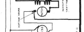
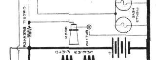
7 correct but voltage low, it Will indicate poor connections at the straps or leaky connections at the top cover, due to dirt, acid or moisture. Each cell should show approximately 2.1 volts if the electrolyte reads as above when tested across the terminals. Next, connect the voltmeter across the positive and negative terminals of the battery. Connect an ammeter as instructed under the heading, "Ammeter Reading on the Model Six-54." Start the engine running, and after allowing it to run for a few minutes, gradually speed it up so that it will show a charging rate not exceeding 20 amperes. During this operation the battery voltage should rise to between 7.2 and 7.5 volts, when the voltage regulator will automatically decrease the ampere charging rate. The ampere charging rate will possibly never reach 20 amperes, regardless of the engine speed if the battery tests from to 1.275, as above. If the voltage rises above 7.5 volts without decreasing the charging rate, move the controlling arm slightly to the right until the voltage - does hold between the points of 7.2 and 7.5 volts. If, on the other hand, the charging rate decreases before the voltage rises to 7.2 volts, move the hand slightly to the left until the charging rate decreases at the correct point. If the battery is discharged to an acid density of or less and the plates are not sulphated, the voltage regulator will allow approximately 25 amperes to pass into the battery, providing the engine speed is sufficient (approximately 30 miles per hour, 1055 R. P. M. There is a resistance between the voltage regulator and the cut out relay, its function being to allow the voltage to build up high enough to bring the voltage regulator into play. The voltage taken at the voltage regulator terminal will, in either case, be from 8 to 8.5 volts before automatically decreasing the charging rate. While in the first instance the battery voltage will read from 7.2 to 7.5 volts, in the second instance the battery voltage will read approximately 6 to 6.5 volts. The wire running from the front terminal of the generator should always be connected to the voltage regulator and not to the relay terminal, and in no case ground the -wire from the small front terminal on the generator to the voltage regulator tube İndications of voltage regulator troubles: (1) The generator will not turn to mesh the gears when the starter button is pressed; (2) The generator will not generate. In order to test for and remedy the above troubles, proceed as follows: Depress the starter button and if the armature does not revolve, remove the lead to the bottom terminal on voltage regulator tube and connect same to the tube above. The armature will not revolve when the starter button is depressed. In order to make repairs, replace tube complete. It is also well to check this out in another way, namely, by allowing the engine to run, and observing whether at normal speed 7

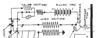
8 the cut out relay will remain open. This will also indicate a burned out voltage regulator resistance. Under these same conditions, if the lead connecting to the binding post at the bottom of the tube is moved up to the tipper connection before referred to, the cut out will immediately be drawn closed and the generator will start to charge the battery. IGNITION TIMING ON THE 1914 AND 1915 MODEL SIX-54 Give full advance to the spark lever on top of steering wheel. Open priming cocks on motor and turn slowly by hand, using the starting crank until the priming cock on No. 1 cylinder begins to blow, indicating that the piston of this cylinder is on the compression stroke. (To determine this, hold the finger over the priming cock.) No. 1 cylinder is due to fire in its advanced position when the line marked which is 6" before the mark DC-1-6 on the flywheel reaches the pointerattached to the crankcase The spark from the magneto circuit takes place when the spring "A" is moved so that the contact points "C" just start to separate. The timer should be adjusted by loosening the cam adjusting screw and revolving the rotor shaft so that when the rotor is in place on this shaft, the contact brush conies under No. 1 terminal on the distributor head. When this position is reached, reset cam adjusting screw. In this position, the back lash in the rotor shaft should be sufficient to just make and break the magneto circuit at contact points "C." The gaps at the contact points "C" should be equal to two thicknesses of paper. such as this sketch is printed on. Replace rotor and distributor, first rubbing a little vaseline on the rotor race. 8
9 ARMATURE TROUBLES AND THEIR REMEDIES For 1914 and 1915 Model Six-54 Failure to turn over at uniform speed when starter pedal is slightly depressed. Blackening and burning of the generator commutator. Failure to keep the battery charged. Slow cranking even with a well charged battery. Excessive heating of the generator. Method of Testing Out the Armature If any of the above indications exist, first see that all connections are complete and made correctly in accordance with wiring diagram. Observe if the commutator has the same appearance all the way around or whether some of the segments are burned more than others. See whether it will turn over uniformly when the starter pedal is depressed slightly. If the generator commutator is burned black on two or more adjacent seg- ments and it revolves unevenly when the pedal is partly depressed, it almost invariably indicates that one or more of the armature coils are shorted, which will entirely eliminate the action of the winding in question so that the armature will revolve only a fraction of a revolution. This will cause the relay to vibrate while the engine is running. If an ammeter is connected into the circuit it will swing back and forth at each revolution both when the engine is running and starter pedal is partly depressed. If this condition exists, 'the winding on the armature may be tested as follows: To Test for Grounds in Armature Winding In order to make the following test, it is advisable to use a 100-volt circuit in series with a 16 candle power Carbon Filament lamp. The test may be made with the generator either mounted or taken from the car. 1. Insulate all brushes from the commutator by placing sheets of paper between them. Then, with the test points, test for a ground from each commutator to the frame, as shown diagramatically below. Neither commutator on either generator or motor winding should show a ground. 1. With the brushes and commutator bars insulated, as in the first test, try for connections between the motor and generator winding, holding one test point on a segment of the motor commutator, and the other on the generator commutator. There should he no connections between the two windings and no grounds indicated. If the motor fails to crank when the battery tests up to normal specific gravity, turn on the head lamps and operate the starter lever. If the lights go out, it indicates a bad cell in the storage battery, or a loose or poor connection either in the cell connectors or at one end of the large cable leading 9
10 of the large cable leading rom the battery to the generator If the light continues to burn but the motor makes no effort to crank, it is caused by poor contact between the motor brushes and commutator, either due to accumulation of dirt or grease, or else to improper spring tension on the motor brushes. When this condition exists, added pressure such as will result from pressing the brushes firmly against the commutator with the fingers will usually result in the armature turning over, proving the contentions as above. 10

11 11
12
SECTION 9 CRANKING SYSTEM CONTENTS
 SECTION 9 CRANKING SYSTEM CONTENTS 9-1. 9-2. 9-3. 9-4. 9-5. 9-6. 9-7. 9-8. GENERAL DESCRIPTION.,...,..., 9-2 SPECIFICATIONS.......................................... 9-4 LUBRICATION 9-5 REMOVAL AND INSTALLATION...
INSTRUCTIONS. Delco Systems
 INSTRUCTIONS FOR THE CARE OF 6-24 Delco Systems The Dayton Engineering Laboratories Co. Dayton, Ohio This is a description of the 6-24 volt system as applied to the following cars: 1912 Cadillac 1913 Cole
STARTER CIRCUIT TROUBLESHOOTING
 2000 Honda Accord EX Sedan V6-3.0L Vehicle > Starting and Charging > Starting System > Starter Motor > Testing and Inspection > Component Tests and General Diagnostics STARTER CIRCUIT TROUBLESHOOTING Starter
 1 of 16 1/10/2015 7:25 AM STARTER MOTOR 2009 Hyundai Accent 1.6L Eng GS REQUESTED INFORMATION DISASSEMBLY 1. Disconnect the M-terminal (A) on the magnet switch assembly (B). Fig 1: Identifying M-Terminal
STARTING & CHARGING SYSTEM SECTIONSC CONTENTS IDX
 STARTING & CHARGING SYSTEM SECTIONSC GI MA EM LC EC CONTENTS FE PRECAUTIONS...2 Supplemental Restraint System (SRS) AIR BAG and SEAT BELT PRE-TENSIONER...2 Wiring Diagrams and Trouble Diagnosis...2 BATTERY...3
Battery Operation. Battery Construction. Battery State Of Charge. Battery Load Test. Battery Rating Systems 2/14/12
 Battery Operation Batteries, Charging and Donald Jones Brookhaven College Batteries convert chemical energy into electrical energy During discharge the battery s plate composition is changed During charging
Unit AE01K Knowledge of Locating and Correcting Simple Electrical Faults in the Automotive Workplace
 Assessment Requirements Unit AE01K Knowledge of Locating and Correcting Simple Electrical Faults in the Automotive Workplace Content: Basic electrical principles a. Explain the direction of current flow
Electrical Systems. Introduction
 Electrical Systems Figure 1. Major Components of the Car s Electrical System Introduction Electricity is used in nearly all systems of the automobile (Figure 1). It is much easier to understand what electricity
./#0#. 1"&." 1994 ELECTRICAL Suzuki of America Corp. - Starters. Swift
 !"" #$%!& '()!)((*(+,*)- 1994 ELECTRICAL Suzuki of America Corp. - Starters Swift Two types of starter motors are used, conventional and reduction gear. Both types of starters consist of yoke assembly,
STARTING SYSTEMS 8B - 1 STARTING SYSTEMS CONTENTS
 TJ STARTING SYSTEMS 8B - 1 STARTING SYSTEMS CONTENTS page DESCRIPTION AND OPERATION STARTER MOTOR... 2 STARTER RELAY... 3 STARTING SYSTEM... 1 DIAGNOSIS AND TESTING STARTER MOTOR... 8 STARTER MOTOR NOISE
STARTING & CHARGING SYSTEM
 K ELECTRICAL SECTION SC A STARTING & CHARGING SYSTEM B C D CONTENTS E PRECAUTIONS... 2 Precautions for Supplemental Restraint System (SRS) AIR BAG and SEAT BELT PRE-TEN- SIONER... 2 Precautions for Power
Automotive Electrical Systems
 Automotive Electrical Systems 1 Electrical Circuits Contain 4 main parts 1. Power source battery alternator 2. Load 3. Control 4. Path 2 3 Batteries What is a Battery? An electrochemical device which stores
Engine Does Not Start or Is Hard to Start Cause of Trouble. 1. Open the drain screw, and check Fuel not supplied (1) Fuel tank empty
 Fuel tank empty") 20. Engine Does Not Start or Is Hard to Start 20-1 Engine Output Insufficient 20-2 Poor Performance at Low Speed and Idling 20-3 Poor Performance at High Speed 20-3 Unsatisfactory Operation 20-4 Fuel Gauge
20. Engine Does Not Start or Is Hard to Start 20-1 Engine Output Insufficient 20-2 Poor Performance at Low Speed and Idling 20-3 Poor Performance at High Speed 20-3 Unsatisfactory Operation 20-4 Fuel Gauge
1984 Jeep CJ7. IGNITION SYSTEM - SOLID STATE' 'Distributors & Ignition Systems MOTORCRAFT SOLID STATE IGNITION (SSI)
") TESTING SECONDARY CIRCUIT CHECK CAUTION: When checking secondary voltage, do not remove spark plug wires from spark plugs No. 3 on 4-cylinder, No. 1 or 5 on 6-cylinder and No. 3 or 4 on V8 Engines. 1.
TESTING SECONDARY CIRCUIT CHECK CAUTION: When checking secondary voltage, do not remove spark plug wires from spark plugs No. 3 on 4-cylinder, No. 1 or 5 on 6-cylinder and No. 3 or 4 on V8 Engines. 1.
STARTING SYSTEM (1ZZ FE) (April, 2003)
 (April, 2003)") STARTING & CHARGING STARTING SYSTEM (1ZZ FE) (April, 2003) STARTING SYSTEM (1ZZ FE) (April, 2003) INSPECTION 19 1 190QO 02 1. INSPECT STARTER ASSY NOTICE: These tests must be performed within 3 to 5 seconds
STARTING & CHARGING STARTING SYSTEM (1ZZ FE) (April, 2003) STARTING SYSTEM (1ZZ FE) (April, 2003) INSPECTION 19 1 190QO 02 1. INSPECT STARTER ASSY NOTICE: These tests must be performed within 3 to 5 seconds
SECTION 1E ENGINE ELECTRICAL
 SECTION 1E ENGINE ELECTRICAL CAUTION: Disconnect the negative battery cable before removing or installing any electrical unit or when a tool or equipment could easily come in contact with exposed electrical
Automatic taper of charge rate for superior battery life through good equalization of cells and low water use rate.
 FEATURES Automatic taper of charge rate for superior battery life through good equalization of cells and low water use rate. Silicon diodes with inherent surge protection operated at a conservative percentage
B, are made of %-in. strap iron. Armature
 # 6-32 HACK SCREWS operating on low-voltage a.c. from a bell transformer is shown in Figs. 1 and 3. The field coils A and B are two magnets from a buzzer or doorbell placed so that the windings run in
Starting and Charging
 The Starting and Charging System is a critical system in your vehicle. The Starting system provides the ability to crank the engine electrically from the drivers position. The first car with electric starting
Electrical Equipment-Maintenance Instructions
 MODEL: SERIES "E" EIGHT No. OF SHEETS 21 SHEET NO. 1 Electrical Equipment-Maintenance Instructions DYNAMO Compensated Voltage Control Types Compensated voltage control type dynamos operate in conjunction
2001 Cougar Workshop Manual
 Page 1 of 7 SECTION 303-06: Starting System 2001 Cougar Workshop Manual DIAGNOSIS AND TESTING Procedure revision date: 09/14/2001 Starting System Refer to Wiring Diagrams Section 303-06 for schematic and
CHAPTER 10 ELECTRIC SYSTEM
 CHAPTER 10 ELECTRIC SYSTEM 1. ELECTRIC SYSTEM ELECTRIC SYSTEM 1.1 WIRING DIAGRAM CK20-USA 196WA00A S196-WOO Jul. 2003 10-3 CK20(M) CHAPTER 10 CK20-EU 196WA51A 10-4 S196-WOO Jul. 2003 ELECTRIC SYSTEM 1.2
Timer. TipTop Timers. Installation and Operation Manual
 TipTop s E TM Installation and Operation Manual Sold by: TipTop s LLC 2225 North Dollar Road Spokane Valley, WA 99212 web: Model T Electronic - E E Conversion Kit Contents The Electronic conversion kit
SECTION 3.00 WARNING WARNING ENGINE STARTUP AND SHUTDOWN PRESTART INSPECTION
 SECTION 3.00 ENGINE STARTUP AND SHUTDOWN PRESTART INSPECTION Be sure that the clutch, circuit breaker, or other main power transmission device is disconnected. Generators develop voltage as soon as the
ENGINE ELECTRICAL Click on the applicable bookmark to selected the required model year
 ENGINE ELECTRICAL 16-1 ENGINE ELECTRICAL CONTENTS CHARGING SYSTEM................ 2 GENERAL INFORMATION................ 2 SERVICE SPECIFICATIONS.............. 3 SPECIAL TOOL......................... 3
STARTING SYSTEM STARTING SYSTEM ST 1
 ST1 ST2 Troubleshooting TROUBLESHOOTING Problem Possible cause Remedy Page Engine will not crank Battery charge low Battery cables loose, corroded or worn Clutch start switch faulty (M/T) Neutral start
Engine Electrical System
 Engine Electrical System 3 Foreword This manual has been prepared by experts and specialists of,engineering Department of Saipa Yadak Company to be used as a guide by the repairers of electrical systems.we
COLT 2310, 2510, AND 2712 COM PACT TRACTORS CHAPTER 9 TROUBLESHOOTING AND ANALYSIS
 COLT 2310, 2510, AND 2712 COM PACT TRACTORS CHAPTER 9 TROUBLESHOOTING AND ANALYSIS 9-A-1 UPON RECEIVING ANENGINE FORRE- PAIR. Learn the history of the unit from the customer. While the customer is present
CHAPTER 22 STARTER Models J05C-TD, J08C-TP and TR
 1 INDEX STARTER 22-1 22-114E-03 CHAPTER 22 STARTER TROUBLESHOOTING...22-2 STARTER...22-4 22 22-2 STARTER 1 page 1 TROUBLESHOOTING Symptom Possible cause Remedy Engine does not crank, or cranks slowly Key
Series 1000 and Figure NOTE: The top terminals are showing normally closed at rest and the middle terminals are normally
 38.18.The red wire on the OCR plug carries battery voltage. Behavior: D.C. battery voltage should show-up on a volt meter when the red probe is touched to this terminal and the black probe is grounded,
66 CHAPTER FOUR. Spark Plug Removal Refer to Figure 28 for spark plug wive routing according to engine.
 66 CHAPTER FOUR IGNITION SYSTEM A mechanical contact breaker point ignition system is used on all engines covered in this manual. The ignition system may use a Delco-Remy, Autolite, Mallory or Prestolite
HE Stewart Vacuum Gasoline System employs a small tank, installed under the hood. This tank is connected by brass tubing to the intake manifold, also
 T HE Stewart Vacuum Gasoline System employs a small tank, installed under the hood. This tank is connected by brass tubing to the intake manifold, also to gasoline supply tank, and to carburetor. Every
GROUP CONTENTS CHARGING SYSTEM IGNITION SYSTEM SPECIAL TOOL GENERAL DESCRIPTION
 16-1 GROUP 16 CONTENTS CHARGING SYSTEM 16-3 GENERAL DESCRIPTION 16-3 SPECIAL TOOL 16-4 CHARGING SYSTEM DIAGNOSIS 16-4 ON-VEHICLE SERVICE 16-6 GENERATOR OUTPUT LINE VOLTAGE DROP TEST 16-6 OUTPUT CURRENT
ELECTRICAL AND INSTRUMENTS
 ELECTRICAL AND INSTRUMENTS 1 Group 8 ELECTRICAL AND INSTRUMENTS CONTENTS BATTERY Paragraph Page Battery Visual Inspection 4 11 Charging the Battery - 8 13 High Rate Discharge Test of Battery Capacity 7
Which one? All are capable of doing the job
 TM9-4910-509-10 Which one? All are capable of doing the job Now is the time to get it off the shelf and get acquainted with it. The LVCT can make you a topnotch vehicle electrical troubleshooter It s a
ENGINE ELECTRICAL SYSTEM Return To Main Table of Contents
 ENGINE ELECTRICAL SYSTEM Return To Main Table of Contents GENERAL... 2 CHARGING SYSTEM... 4 STARTING SYSTEM... 23 IGNITION SYSTEM... 32 AUTOMATIC SPEED CONTROL (CRUISE) SYSTEM... 43 GENERAL GENERAL SPECIFICATIONS
STARTER - HITACHI Isuzu Trooper II DESCRIPTION TESTING STARTER PERFORMANCE TESTS Starters HITACHI. Isuzu
 STARTER - HITACHI 1986 Trooper II 1984 Starters HITACHI DESCRIPTION Starter is a conventional 12-volt, 4-pole brush-type motor, with direct or reduction gear drive. The starter-mounted solenoid shifts
INDEX Section Page Number Remarks
 INDEX Section Page Number Remarks Synchronous Alternators 2 4 General Fault Finding Capacitors 5 6 Fault Finding & Testing Diodes,Varistors, EMC capacitors & Recifiers 7 10 Fault Finding & Testing Rotors
DIAGNOSIS AND TESTING Procedure revision date: 06/21/2000
 2001 F-350 Applies to: Gasoline Report a problem with this article Subarticles Inspection and Verification Symptom Chart Pinpoint Tests Component Tests SECTION 303-06A: Starting System Gasoline Engines
2000 F-150 Workshop Manual
 Page 1 of 14 SECTION 303-06: Starting System 2000 F-150 Workshop Manual DIAGNOSIS AND TESTING Procedure revision date: 06/17/1999 Starting System Refer to Wiring Diagrams Cell 20, Starting System for schematic
STARTING/CHARGING SYSTEMS Brought to you by Eris Studios NOT FOR RESALE
 STARTING/CHARGING SYSTEMS General Description 1. General Description A: SPECIFICATION Vehicle model Starter Generator Item Specification Type Reduction type Model 428000-5760 Manufacturer DENSO Voltage
9.7 Replacement of the compressed air distributor
 9.6.6 9.6.7 screw in the bolt and to increase unscrew the bolt. For a complete rotation of the bolt, the variation is of 1mm. After measuring the pointer position and the compensatory adjustment screw
23. ELECTRIC STARTER (TRX450ER)
") 23. ELECTRIC STARTER (TRX450ER) COMPONENT LOCATION 23-2 STARTER MOTOR 23-6 SYSTEM DIAGRAM 23-2 STARTER RELAY SWITCH 23-13 SERVICE INFORMATION 23-3 CLUTCH DIODE 23-14 TROUBLESHOOTING 23-4 23-1 COMPONENT
23. ELECTRIC STARTER (TRX450ER) COMPONENT LOCATION 23-2 STARTER MOTOR 23-6 SYSTEM DIAGRAM 23-2 STARTER RELAY SWITCH 23-13 SERVICE INFORMATION 23-3 CLUTCH DIODE 23-14 TROUBLESHOOTING 23-4 23-1 COMPONENT
STARTING SYSTEM TEST STARTING SYSTEM
 2013 Dodge or Ram Truck RAM 1500 Truck 2WD V8-5.7L Vehicle > Starting and Charging > Starting System > Testing and Inspection > Component Tests and General Diagnostics STARTING SYSTEM TEST STARTING SYSTEM
INDEX Page GENERAL INSTRUCTIONS 2
 INDEX Page GENERAL INSTRUCTIONS 2 ASSEMBLY OF HUBS FITTED WITH TAPER ROLLER BEARINGS Preparation 2 Fitting 3 Adjustment 3 BRAKES Axles fitted with Girling brakes 4 Axles fitted with Lockheed brakes 4 Brake
Return to Main Table of Contents GENERAL... 2 IGNITION SYSTEM... 4 CHARGING SYSTEM STARTING SYSTEM CRUISE CONTROL SYSTEM...
 ENGINE ELECTRICAL SYSTEM Return to Main Table of Contents GENERAL... 2 IGNITION SYSTEM... 4 CHARGING SYSTEM... 13 STARTING SYSTEM... 29 CRUISE CONTROL SYSTEM... 38 27-2 GENERAL GENERAL SPECIFICATIONS Distributor
RELEASING PRESSURE IN THE HYDRAULIC SYSTEM,
 Testing And Adjusting Introduction NOTE: For Specifications with illustrations, make reference to SPECIFICATIONS for 225 EXCAVATOR HYDRAULIC SYSTEM, Form No. SENR7734. If the Specifications are not the
ST- 1 STARTING SYSTEM. Page TROUBLESHOOTING... ST-2 STARTER... ST-3 STARTER RELAY... ST- 12 CLUTCH START SWITCH... ST-1 2
 ST- 1 STARTING SYSTEM Page TROUBLESHOOTING... ST-2 STARTER... ST-3 STARTER RELAY... ST- 12 CLUTCH START SWITCH... ST-1 2 ST-2 STARTING SYSTEM - Troubleshooting TROUBLESHOOTING Problem Possible cause Remedy
Electric Brakes. Braking Systems - Electric
 Electric Brakes The electric brakes on your trailer are similar to the drum brakes on your automobile. The basic difference is that your automotive brakes are actuated by hydraulic pressure while your
1 THE WOLVERTON SYSTEM OF TRAIN LIGHTING.
 1 THE WOLVERTON SYSTEM OF TRAIN LIGHTING. The Wolverton equipment is a single battery system utilising a plain shunt wound dynamo. The dynamo is controlled by an automatic field regulator which senses
REMY TECHNICAL SERVICE BULLETIN
 June 2018 REMY TECHNICAL SERVICE BULLETIN Remy Power Products is continuously adding technical training and technical information. We welcome suggestions. If there is something technical you would like
1994 Mazda MX-5 Miata. STARTER - REDUCTION GEAR 1994 ELECTRICAL Mazda Starter - Reduction Gear
 DESCRIPTION STARTER - REDUCTION GEAR 1994 ELECTRICAL Mazda Starter - Reduction Gear The Nippondenso reduction gear starter is a conventional 12-volt, 4-pole, brush-type starter. The integral solenoid is
DEFOGGER SYSTEM PARTS LOCATION
 BE61 PARTS LOCATION TROUBLESHOOTING The table below will be useful for you in troubleshooting these electrical problems. The most likely causes of the malfunction are shown in the order of their probability.
20. ELECTRIC STARTER 20-1 SYSTEM DIAGRAM 20-2 STARTER MOTOR 20-6 SERVICE INFORMATION 20-3 STARTER RELAY SWITCH TROUBLESHOOTING 20-4 DIODE 20-15
 20. SYSTEM DIAGRAM 20-2 SERVICE INFORMATION 20-3 TROUBLESHOOTING 20-4 STARTER MOTOR 20-6 STARTER RELAY SWITCH 20-13 DIODE 20-15 20 20-1 SYSTEM DIAGRAM IGNITION SWITCH ENGINE STOP SWITCH CLUTCH SWITCH STARTER
T-3161-T Texas T Distributor
 T-3161-T Texas T Distributor NOTE: Please read completely through the instructions before installing your distributor. It will insure your installation goes smoothly. If you have installed a distributor
Motronic ignition system, servicing
 Page 1 of 25 28-2 Motronic ignition system, servicing Note: Motronic Engine Control Module (ECM) J220* with connector page 24-9, item 16. 1 - Highvoltage ignition cable Ignition secondary circuit Check
ELECTRICAL SYSTEM CONTENTS LOCATION OF ELECTRICAL COMPONENTS 5-1 IGNITION SYSTEM 5-3 CHARGING SYSTEM 5-7
 ELECTRICAL SYSTEM CONTENTS LOCATION OF ELECTRICAL COMPONENTS 5-1 IGNITION SYSTEM 5-3 CHARGING SYSTEM 5-7 STARTER SYSTEM AND SIDE STAND IGNITION INTERLOCK SYSTEM 5-11 SWITCHES 5-15 LAMP 5-16 BATTERY 5-18
STARTER Mitsubishi Montero DESCRIPTION BENCH TESTING STARTER NO-LOAD TEST ELECTRICAL Mitsubishi Starters. Montero
 STARTER 1993 Mitsubishi Montero 1993 ELECTRICAL Mitsubishi Starters Montero DESCRIPTION The starter is a conventional 12-volt, 4-pole brush-type motor, with gear reduction drive. The starter-mounted solenoid
ELECTRICAL GROUP 8 CONTENTS. Page PART 2 STARTING MOTOR (DIRECT DRIVE) PART 2 STARTING MOTOR (REDUCTION GEAR TYPE)
 PART 2 STARTING MOTOR (REDUCTION GEAR TYPE)") ELECTRICAL 8-1 ELECTRICAL GROUP 8 CONTENTS PART 1 BATTERY Page Adjustment of Acid Gravity 10 Battery Visual Inspection 7 Charging the Battery High Rate Discharge Test 9 of Battery Capacity 9 Page Service
ELECTRICAL 8-1 ELECTRICAL GROUP 8 CONTENTS PART 1 BATTERY Page Adjustment of Acid Gravity 10 Battery Visual Inspection 7 Charging the Battery High Rate Discharge Test 9 of Battery Capacity 9 Page Service
Starting Systems & Traction Motor Systems. ATASA 5 th. ATASA 5 TH Study Guide Chapter 18 Pages Starting & Traction Motor Systems 62 Points
 ATASA 5 TH Study Guide Chapter 18 Pages 537 570 Starting & Traction Motor Systems 62 Points Please Read The Summary 1. Electric are used to start the engine & in hybrids are used to move the vehicle. Motors
1997 Mazda MX-5 Miata. STARTER - DIRECT DRIVE 1997 STARTING & CHARGING SYSTEMS Mazda - Starters - Direct Drive
 STARTER - DIRECT DRIVE 1997 STARTING & CHARGING SYSTEMS Mazda - Starters - Direct Drive DESCRIPTION & OPERATION Direct drive starter is a conventional 12-volt, 4-pole, brush-type starter. The integral
5-2 FUEL SYSTEM AND THROTTLE BODY FUEL SYSTEM FUEL DELIVERY SYSTEM The fuel delivery system consists of the fuel tank, fuel pump, fuel filters, fuel f
 FUEL SYSTEM AND THROTTLE BODY 5-1 FUEL SYSTEM AND THROTTLE BODY I CONTENTS FUEL SYSTEM 5-2 FUEL DELIVERY SYSTEM 5-2 FUEL PUMP 5-3 FUEL PRESSURE REGULATOR 5-4 FUEL INJECTOR 5-4 FUEL PUMP CONTROL SYSTEM
ON-VEHICLE INSPECTION
 CH2 P11586 CHARGING CHARGING SYSTEM ONVEHICLE INSPECTION 1. CHECK BATTERY ELECTROLYTE LEVEL Check the electrolyte quantity of each cell. MaintenanceFree Battery: CH03L01 If under the lower level, replace
ELECTRICAL. Contents - Wiring Diagrams
 Contents - Wiring Diagrams T-Bar (Floating Deck - Hydro)............................................ 8-16 T-Bar (Fixed Deck - Gear)............................................... 8-17 T-Bar (Fixed Deck
1994 Mazda MX-5 Miata. STARTER - DIRECT DRIVE 1994 ELECTRICAL Mazda Starter - Direct Drive
 DESCRIPTION STARTER - DIRECT DRIVE 1994 ELECTRICAL Mazda Starter - Direct Drive Nippondenso direct drive starter is a conventional 12-volt, 4-pole, brush-type starter. The integral solenoid is attached
TM-1620 OPERATING INSTRUCTIONS AND OWNERS MANUAL
 TM-1620 OPERATING INSTRUCTIONS AND OWNERS MANUAL tracopackaging.com 800-284-WRAP 620 SOUTH 1325 WEST OREM, UT. PHONE 800-284-WRAP (9727) IMPORTANT: READ ALL INSTRUCTIONS BEFORE OPERATING EQUIPMENT Your
ITEMS PISTON STOP SECTION 14 TOOLS SPECIAL PART NO PART NO CRANKSHAFTGUIDE D SERIES GOV RNOR ADJUSTING GAUGE C SERIES
 SECTION 14 TOOLS SPECIAL ITEMS PISTON STOP USED ON ALL BOY ENGINES. MODELS OF LAWN- PART NO. 426814 Used to hold flywheel in place while loosening or tightening flywheel nut. Remove spark pug and install
ELECTRICAL. CDTA Technical Training Center
 ELECTRICAL ATOMIC STRUCTURE Protons positive charge Electron negative charge Neutron - neutral Electricity is the movement of electrons from atom to atom ELECTRON FLOW CONDUCTOR - Materials which have
Air Cooled Engine Technology. Roth 9 th Ch 14 Elect. System Service Pages
 Roth 9 th Ch 14 Elect. System Service Pages 245 276 1. is the term used to describe periodic, preventative maintenance done to the ignition system of any engine. It may often times also include fuel system,
PROCESS ELECTRONICS CORPORATION
 MINIVERTER MANUAL PROCESS ELECTRONICS CORPORATION 100 BRICKYARD ROAD MOUNT HOLLY, NORTH CAROLINA 28120 TELEPHONE (800) 421-9107 FAX (704) 827-9595 SALES@PECRECTIFIER.COM WWW.PECRECTIFIER.COM SOLID STATE
Instruction Model 18537
 Instruction 738-556 Model 18537 LIMITED WARRANTY H. D. Hudson Manufacturing Company warrants to the original purchaser only that this product will continue to function as intended if used in accordance
Electric Brakes. Braking Systems - Electric
 Electric Brakes The electric brakes on your trailer are similar to the drum brakes on your automobile. The basic difference is that your automotive brakes are actuated by hydraulic pressure while your
SECTION M. ELECTRICAL. Section Description Page No.
 SECTION M. ELECTRICAL. Section Description Page No. M.1 General Page 2 M.2 Alternator Page 2 M.3 Battery Page 7 M.4 Hazard Warning System Page 7 M.5 Brake Fail Warning System Page 8 M.6 Seat Belt Warning
WEBER CARBURETOR TROUBLESHOOTING GUIDE
 This guide is to help pinpoint problems by diagnosing engine symptoms associated with specific vehicle operating conditions. The chart will guide you step by step to help correct these problems. For successful
SERVICE BULLETIN REFERENCES 17-1
 SERVICE BULLETIN REFERENCES 17-1 ENGINE TEAR DOWN Engine tear down and assembly is easy if done right. Use the right tools, disassemble in correct order, and remove complete assemblies intact where possible.
Coolant System CHAPTER VI 2º F. 30º F. Freezing point... Degrees of frost... -3º F. 35º F. 12º F. 20º F. 10º F. 11 pts. 11pts. 4½ pts. 4½ pts.
 46 ROLLS-ROYCE 25-30 H.P. CAR - Fan. CHAPTER VI Coolant System Collant Pump - Radiator Shutters - Coolant Level - Frost Precautions Coolant Pump. The centrifugal coolant circulating pump is fitted with
ELECTRICAL BATTERY/STARTING/CHARGING SYSTEMS DIAGNOSTICS
 Z ELECTRICAL 8A - 1 ELECTRICAL GROUP INDEX page AUDIO SYSTEMS... 8F BATTERY/STARTER/GENERATOR SERVICE... 8B BATTERY/STARTING/CHARGING SYSTEMS DIAGNOSTICS... 8A CHIME WARNING/REMINDER SYSTEM... 8U HORNS...
WHEEL HORSE LAWN TRACTOR
 FORM NO. 897 WHEEL HORSE LAWN TRACTOR FOR AND 8 MOWERS SET-UP INSTRUCTIONS Loose Parts Note: Use the chart below to verify all parts have been shipped. DESCRIPTION QTY. USE Front Wheel Shim Washer (as
STARTER SYSTEM TESTING 5.6
 STARTER SYSTEM TESTING 5.6 ON-MOTORCYCLE TESTS Starter Relay Test NOTE Starter relay test also applies to ignition and key switch relays.. See Figure 5-5. Locate starter relay. The relay is attached to
THIS PRODUCT IS FOR PROFESSIONAL LABORATORY USE ONLY USER'S MANUAL. WELLS ENGINE UNIT 230 VOLT Product No. U905, U906, U907, U908
 DENTAL, INC. TECHNICAL BULLETIN U807-022510 5860 FLYNN CREEK ROAD READ ALL INSTRUCTIONS P.O. BOX 106 BEFORE PROCEEDING COMPTCHE, CALIFORNIA, U.S.A. 95427 SAVE THIS FOR FUTURE REFERENCE THIS PRODUCT IS
ELECTRICAL SYSTEM. Section VI CONTENTS. Page. Battery 6. Removal of Starter 10. Disassembling the Starter 10. Testing the Armature 10
 CHRYSLER SERVICE MANUAL ELECTRICAL SYSTEM 1 Section VI ELECTRICAL SYSTEM CONTENTS Page Battery 6 Removal of Starter 10 Disassembling the Starter 10 Testing the Armature 10 Assembling the Starter 11 Generator
CHARGING SYSTEM 8C - 1 CHARGING SYSTEM CONTENTS
 ZG CHARGING SYSTEM 8C - 1 CHARGING SYSTEM CONTENTS page GENERAL INFORMATION OVERVIEW... 1 DESCRIPTION AND OPERATION BATTERY TEMPERATURE SENSOR... 2 CHARGING SYSTEM OPERATION... 1 ELECTRONIC VOLTAGE REGULATOR...
1993 ELECTRICAL Volkswagen Starters - Bosch. Volkswagen; Cabriolet, EuroVan, Golf, GTI, Jetta
 Article Text ARTICLE BEGINNING 1993 ELECTRICAL Volkswagen Starters - Bosch Volkswagen; Cabriolet, EuroVan, Golf, GTI, Jetta DESCRIPTION Starter is a brush type, series-wound electric motor with an overrunning
Ignition Installation Troubleshooting Tips/Frequently-Asked Questions
 Ignition Installation Troubleshooting Tips/Frequently-Asked Questions Warning: Reversing the red and black ignition wires will destroy the ignition module and void the warranty. The Hot-Spark module s
1.CONTENTS 1. Contents Control location Before riding Safe riding Driving Use genuine spare parts Use
 1.CONTENTS 1. Contents... 1 2. Control location... 3 3. Before riding... 4 4. Safe riding... 4 5. Driving... 5 6. Use genuine spare parts... 5 7. Use of each component... 6 Gauges... 6 Operation of ignition
Contents INTRODUCTION... 2 CHECK YOU HAVE RECEIVED... 4 WHAT YOU WILL NEED...4 TECHNICAL CHARACTERISTICS...5 WIRING DIAGRAMES...6 CABLES...
 Contents Page INTRODUCTION... 2 CHECK YOU HAVE RECEIVED... 4 WHAT YOU WILL NEED...4 TECHNICAL CHARACTERISTICS...5 WIRING DIAGRAMES...6 CABLES...6 BATTERY...7 CHARGE CONTROLLER...8 FUSE...8 TOWERS...8 INSTALLATIONS...9
BASIC ELECTRICS MECHANICS BASIC LEVEL. An initiative of:
 BASIC ELECTRICS 2 BASIC LEVEL MECHANICS An initiative of: Table of Contents TRANSMISSIONS AND DRIVETRAIN 1. Basic Electrics 1 1.1 Introduction 1 1.2 Charging Circuit 2 1.2.1 The Battery 2 2. Generators
Troubleshooting Guide for N1225-1/N1237-1/N Alternators
 Troubleshooting Guide for N1225-1/N1237-1/N1505-1 Alternators Hazard Definitions These terms are used to bring attention to presence of hazards of various risk levels or to important information concerning
ENGINE TUNE-UP INSPECTION OF ENGINE COOLANT INSPECTION OF ENGINE OIL INSPECTION OF BATTERY. INSPECTION OF AIR FILTER (Paper Filter Type)
") ENGINE MECHANICAL - Engine Tune-Up EM-17 ENGINE TUNE-UP INSPECTION OF ENGINE COOLANT (See steps 1 and 2 on page CO-4) INSPECTION OF ENGINE OIL (See steps 1 and 2 on page LU-5) INSPECTION OF BATTERY (See
ENGINE MECHANICAL - Engine Tune-Up EM-17 ENGINE TUNE-UP INSPECTION OF ENGINE COOLANT (See steps 1 and 2 on page CO-4) INSPECTION OF ENGINE OIL (See steps 1 and 2 on page LU-5) INSPECTION OF BATTERY (See
Troubleshooting 3Z8 038 Rev B
 Troubleshooting 3Z8 038 Rev B INSTRUCTIONS WARNING INJECTION HAZARD This form is only a quick reference for troubleshooting Graco sprayers. To reduce the risk of serious injury, including fluid injection,
ENGINE AND EMISSION CONTROL
 17-1 ENGINE AND EMISSION CONTROL CONTENTS ENGINE CONTROL SYSTEM........ 3 SERVICE SPECIFICATION............... 3 ON-VEHICLE SERVICE.................. 3 Accelerator Cable Check and Adjustment... 3 ACCELERATOR
DESCRIPTION & OPERATION
 STARTER - REDUCTION GEAR 1997 STARTING & CHARGING SYSTEMS Mazda - Starters - Reduction Gear DESCRIPTION & OPERATION Reduction gear starter is a conventional 12-volt, 4-pole, brush-type starter. The integral
Electric Trolling Motor
 Electric Trolling Motor L Series User s Manual Please read and retain this manual before using product REACH RoHS TABLE OF CONTENTS Contents GENERAL INFORMATION 4 SPECIFICATIONS 4 WIRING AND BATTERY RECOMMENDATIONS
1991 Mazda MX-5 Miata. STARTER - DIRECT DRIVE ELECTRICAL Mazda Starters - Direct Drive ELECTRICAL Mazda Starters - Direct Drive
 DESCRIPTION STARTER - DIRECT DRIVE 1990-92 ELECTRICAL Mazda Starters - Direct Drive Nippondenso direct drive starter is a conventional 12-volt, 4-pole, brush-type starter. The integral solenoid is attached
User s Manual. Automatic Switch-Mode Battery Charger
 User s Manual Automatic Switch-Mode Battery Charger IMPORTANT Read, understand, and follow these safety rules and operating instructions before using this battery charger. Only authorized and trained service
C.E. Niehoff & Co. N1601, N1602, N1603, and N1604 Alternator Troubleshooting Guide NOTICE. Hazard Definitions. Battery Charge Volt and Amp Values
 C.E. Niehoff & Co. N1601, N1602, N1603, and N1604 Alternator Troubleshooting Guide Hazard Definitions These terms are used to bring attention to presence of hazard(s) of various risk levels or to important
Stewart-Warner Electronic Tachometer 54.07
 General Description General Description Engine speeds are shown in revolutions-per-minute (rpm) by the electronic tachometer (Fig. 1). The tachometer is used as a guide for shifting, and to keep the engine
AUTOMOTIVE ENGINEERING SECTION
 PURPOSE OF IGNITION SYSTEM The ignition system supplies high-voltage surges as high as 47,000 volts (in some electronic systems) to the spark plugs in the engine cylinders. These surges produce electric
Battery Tester. GxT Incorporated, Cheboygan MI, U.S.A. All Rights Reserved E040-01G. 40 & 42HD Operator s Manual
 Battery Tester GxT Incorporated, Cheboygan MI, U.S.A. All Rights Reserved E040-01G 40 & 42HD Operator s Manual SPECIFICATIONS Measurement Range...Ferret 40... Ferret 42HD Battery Volts... 4.0 to 19.99...
CAUTION: READ INSTRUCTIONS CAREFULLY BEFORE STARTING INSTALLATION
 V-Twin MFG. VT No. 32-9500 V-TECH 1 IGNITION KIT, SINGLE FIRE FITS EV SHOVEL, XL THRU 1997 VT No. 32-9503 V-TECH 1 IGNITION KIT, SINGLE FIRE FITS EV, SHOVEL, XL, WITH COIL AND WIRES This is a custom application