TILLOTSON LTD., CLASH INDUSTRIAL ESTATE, TRALEE, CO. KERRY, IRELAND PHONE: FAX:
|
|
|
- Rosamund Logan
- 6 years ago
- Views:
Transcription
1 TILLOTSON LTD., CLASH INDUSTRIAL ESTATE, TRALEE, CO. KERRY, IRELAND PHONE: FAX: SERIES SERVICE MANUAL


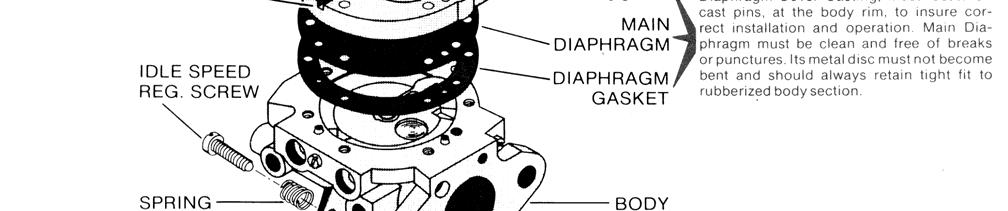
2 INTRODUCTION The gasoline engine industry s universal acceptance of Tillotson s original diaphragm carburetor has resulted in the development, by Tillotson engineers, of the HL Series carburetor. Designed with a minimum of parts, this lightweight, compact carburetor includes an integral fuel pump and filter in one small unit. The all position mounting feature allows a wide range of possible applications. Information contained in the following pages is presented as an aid to understanding construction, operation and servicing of the HL series carburetor. HL SCHEMATIC Note: On some models a one piece Idle Adjustment Screw (ref. 7) & Main Adjustment Screw (ref. 19) with rubberized O ring attached (not illustrated above) are used. 1. Fuel Inlet 2. Fuel Pump Body 3. Fuel Pump Diaphragm 3A. Diaphragm Pump Inlet Valve 3B. Diaphragm Pump Outlet Valve 4 Fuel Pump Gasket 5 Diaphragm Cover Gasket 6 Metering Chamber 7 Idle Adjustment Screw 8 Impulse Channel 9 Idle Fuel Adjustment Orifice 10A. Primary Idle Discharge Port 10B. Secondary Idle Discharge Port 11. Throttle Shutter 12. Main Fuel Adjustment Orifice 13. Body 14. Venturi 15. Main Fuel Discharge Port 16. Choke Shutter 17. Fuel Inlet Supply Channel 18. Inlet Needle & Seat 18A. Copper Gasket 19. Main Adjustment Screw 20. Inlet Tension Spring 21. Inlet Control Lever 22. Fulcrum Pin 23. Atmospheric Vent Hole 24. Diaphragm Cover 25. Diaphragm 26. Atmospheric Chamber 27. Strainer Gasket 28. Fuel Inlet Screen 29. Strainer Cover Retaining Screw 30. Fuel Chamber 31. Pulse Chamber 32. Strainer Cover 2
3 CONSTRUCTION DATA The HL series carburetor is a lightweight, aluminium die cast carburetor composed of four basic parts: metering body, main diaphragm cover plate, fuel pump body and strainer cover. The diaphragm carburetor incorporates many of the same type components found in float type carburetor: choke, throttle, idle and main mixture adjustment screws, idle speed screw and inlet needle and seat. Two styles of main and idle adjustment screws are available: O ring type and spring loaded packing type. Both types are designed to perform the dual purpose of sealing the metering chamber and providing adjustment screw friction. A special insert, housed in a brass cage, forms a seat for the inlet needle. An inlet tension spring exerts a pre-determined force on the inlet control lever, which holds the needle on its seat. A metering diaphragm is subjected to engine suction on the metering chamber side and atmospheric pressure on the vented side. Atmospheric pressure on the vented side pushes the diaphragm toward the inlet control lever, opening the inlet needle to allow fuel to enter the metering chamber, from which it is then delivered into the mixing passages. The vented side of the metering diaphragm may be vented either directly to the atmosphere, or in the case of the balanced carburetor, may be balanced (internally vented) to the choke bore. The balanced type can be recognised by a brass tube in the choke bore which is connected internally to the vented side of the diaphragm. The purpose of internal balance is to offset the enriching or choking effect of a partially dirty air cleaner. Some carburetor metering systems include a ball check type main nozzle. These can be identified by the brass cage located in the venturi choke band of the body casting. The ball check valve allows fuel to flow into the mixing passage and prevents air from flowing into the metering chamber. The movement of the pump diaphragm draws fuel into the fuel chamber and a reverse movement of the diaphragm forces fuel out of the fuel chamber through the inlet needle and seat into the metering chamber. Movement is caused by pulsation from the engine, acting on the diaphragm. A plastic turret inlet connection is the cover to the fuel strainer section of the carburetor and can be rotated 360 degrees for any required fuel connection location. The strainer consists of a fine mesh screen to insure clean fuel supply to the metering section of the carburetor. ADJUSTMENT INSTRUCTIONS To properly adjust carburetor for best performance the engine must be thoroughly warm. INITIAL ADJUSTMENTS: To start a cold engine, first carefully close, by turning clockwise, both idle and main adjustment screws. Open main adjustment screw counter clockwise approximately one an one quarter (1¼) turns. Open idle adjustment screw three quarters (¾) turn. Back idle speed regulating screw off its contact with throttle stop lever, then turn it inward about one (1) full turn so as to slightly open throttle shutter. Open fuel line shut off valve, close choke shutter, partly open throttle shutter and pull starting cord. When engine fires, open choke shutter slightly and idle the engine. Do not race engine. Then as engine warms, open choke shutter. To start a warm engine it should only be necessary to pull starting cord, if the carburetor is properly adjusted. FINAL ADJUSTMENTS: Completely close throttle shutter and readjust idle speed regulating screw so engine idle speed is approximately 1200 RPM for lawn mowers 2000 to 2500 RPM for chain saws then slowly readjust idle adjustment screw to obtain smooth and even engine performance. Poor acceleration may result from setting the idle mixture too lean. DO NOT FORCE ADJUSTMENTS INTO SEATS! 3


4 STARTING CHOKE OPERATION Starting an engine with the HL Carburetor involves the same methods that are used in a conventional float feed carburetor. However, since a diaphragm carburetor does not have the advantage of a great reservoir of fuel upon which to operate, the technique changes somewhat. When starting a cold engine, place the choke shutter in the closed position and throttle shutter in a cracked or open position. Several pulls on the starter may be needed to raise the fuel pressure to the required amount. As the engine is pulled through with the choke in closed position, engine suction will be transmitted to the diaphragm fuel chamber through both primary and secondary idle discharge parts as well as the main fuel discharge part, creating a low pressure area on the fuel side of the main diaphragm. Atmospheric air pressure on the opposite side will force the main diaphragm upward causing the diaphragm button to depress the inlet control lever, overcoming inlet tension spring pressure, permitting fuel to enter through the inlet seat, by forcing inlet needle off its seat contact, then into the fuel chamber side of main diaphragm, up through the idle and main fuel supply orifices and channels, and out the discharge parts to the engine. In starting an engine that has been idle and not running for more than an hour, it will be necessary to operate and manoeuvre the choking mechanism for approximately three (3) to ten (10) seconds depending on how cold the engine has become. The length of time spent warming the engine is only necessary to the extent that the engine can be made to idle, accelerate and run satisfactorily under wide open throttle conditions. IDLING OPERATION When engine is idling, throttle shutter is in a partially cracked position. Engine suction is transmitted through the primary idle fuel discharge port to the fuel chamber side of main diaphragm via the idle fuel supply channel. Again, the main diaphragm is forced upward by atmospheric pressure, depressing the inlet control lever overcoming inlet tension spring pressure and permitting fuel to enter through inlet seat, by forcing inlet needle off its seat contact, and filling the fuel chamber side of main diaphragm. The fuel is then drawn up through idle fuel adjustment orifice and delivered to the engine through primary idle discharge port. 4


5 INTERMEDIATE OPERATION Fuel is delivered into and through the carburetor in the same manner as when the engine is idling. However, as the throttle opens and engine speed increases, more fuel is demanded from the carburetor and supplied to the engine by valving in the secondary idle discharge port located immediately behind the throttle shutter. As the throttle shutter continues to open and engine speed increases, the velocity of air through the venturi creates a low-pressure area at the venturi throat and diminishes the suction on engine side of the throttle shutter. When the pressure at the venturi throat is less than existing within main diaphragm fuel chamber, fuel is drawn up through main fuel adjustment orifice and out main fuel discharge port into air stream entering engine intake. HIGH SPEED OPERATION As the throttle shutter progressively opens from intermediate position to full open position, the air velocity through the venturi increases and fuel is metered up through main fuel adjustment orifice and main fuel discharge port in accordance with the power requirements of the engine. The action of the main diaphragm is the same as previously described with suction required to operate the diaphragm being transmitted through the main fuel discharge port. SUPPLY FUEL ATMOSPHERIC AIR FUEL UNDER PRESSURE PUMP IMPULSE AIR FUEL UNDER VACUUM 5

6 HOW TO DISASSEMBLE FOR CLEANING AND REPAIR The model "HL" carburetor can be cleaned under adverse conditions - working on a clean surface with a minimum of tools. Before disassembling carburetor it is IMPERATIVE to flush it clean of sawdust and dirt by pouring gasoline over it and tools. 1. Remove strainer cover retaining screw and plastic cover. 2. Remove strainer cover gasket and strainer screen. 3. Remove screws and fuel pump body. 4. Remove fuel pump diaphragm and gasket. 5. Remove main diaphragm cover plate. 6. Remove main diaphragm. 7. Remove main diaphragm gasket. 8. Remove inlet control lever fulcrum pin, lever and tension spring. 9. Remove inlet needle. 1. Remove idle and main adjustment screws. 2. When reinstalling "O" ring type adjustment screws, lubricate with #30 SAE oil to prevent seizing. Packing spring type adjustments to not require lubrication. 3. The ball check type main nozzle can be removed by tapping it out of the body casting into the venturi with a small punch. A replacement ball check nozzle should be pressed into the casting with the cross holes in line with the main adjustment needle. The brass cage should be pressed flush with the metering chamber casting. Before reassembling the carburetor (in reverse order as outlined above), wash ALL component parts in clean gasoline and blow off with compressed air. The channels in the metering body should be cleaned by blowing through the idle and main adjusting orifices. All fuel passages in the three castings should be cleaned with compressed air. Do not clean orifices or passages with wires or drills as this might cause damage and incorrect operation of the carburetor. 10. With a thin wall 5/16" Hex socket carefully remove the inlet seat. Remove inlet seat gasket. When reinstalling seat, tighten only from inch-pounds or 34Kg-Cm. SERVICE HINTS When reassembling the inlet control lever and spring, care should be taken to see that the spring rests in the well of the metering body and locates on the dimple of the inlet control lever, (as illustrated below). CAUTION: Do not stretch spring. Inlet control lever is properly set when flush with floor of diaphragm chamber. Be certain main diaphragm, gasket and cover casting are carefully fitted over the three small pins cast in rim at bottom of metering body; also the fuel pump gasket, diaphragm and fuel pump body, over similar pins at bottom rim of main diaphragm cover casting. Evenly tighten fuel pump body retaining screws to insure complete seal of casting separations at both diaphragms. Frequent cleaning or replacement of fuel strainer screen will aid satisfactory operation of the carburetor. CAUTION: Under extreme conditions of clogged idle fuel supply channel and discharge ports, it may be necessary to remove the channel welch plug. If so, it must be very carefully done in following manner: 1. Drill a 1/8 " diameter hole through the 3/8 diameter welch plug. This hole should just break through the welch plug. Depper drilling will seriously damage the body casting and its discharge ports located close behind the welch plug. On some models an additional smaller 1/4 " diameter channel welch plug is used. It is not necessary to remove this plug. 2. Carefully pry out welch plug, then clean discharge ports and cross channels. Now install new part (3/8" diameter, 1/32" thick) welch plug by placing it in casting shoulder, convexed side upward; then flatten to a tight fit with a 5/16" diameter flat end tool. 6
7 TROUBLE SHOOTING Carburetor Floods 1. Dirt or foreign particles preventing Remove, clean and replace. inlet needle from seating. 2. Diaphragm lever spring not seated on lever dimple. Remove, lever and reinstall 3. Diaphragm improperly installed in carburetor. Replace diaphragm or correct installation. Engine will Not Accelerate. 1. Idle adjusting screw set too lean. Enrich idle adjustment 2. Incorrect setting on diaphragm lever. Reset 3. Diaphragm cover plate loose. Tighten 4. Diaphragm gasket leaking. Replace 5. Main fuel orifice plugged. Remove diaphragm cover, diaphragm lever and main adjusting screw. Clean out orifice by blowing through main adjustment threaded hole. Engine Will Not Idle 1. Incorrect idle adjustment. Reset to best idle. 2. Idle discharge ports or channels clogged. Blow out with compressed air, or, if compressed air is not available, clean and flush with gasoline. 3. Diaphragm lever set incorrectly. Reset diaphragm lever so it is flush with the floor of the diaphragm chamber. 4. Throttle shutter cocked in the throttle Reset bore causing fast idle. 5. Dirt nozzle check valve. Clean or replace 6. Welch plug covering the idle discharge ports Replace welch plug, following does not seal. This causes the engine to idle instructions outlined in service hints. with idle adjustment shut off. Engine Runs Out Lean 1. Tank vent not operating correctly. Clean, if possible, or replace 2. Leak in fuel system from tank to pump Tighten or replace fittings or line 3. Ruptured fuel pump diaphragm. Replace 4. Main fuel orifice plugged. Clean Carburetor Runs Rich With Main Adjustment Shut Off 1. The 1/8 " diameter nozzle channel plug, or nozzle Install new plug or new cage check valve cage, is not sealing. NOTE:IN MAKING CARBURETOR ADJUSTMENTS TURN ADJUSTMENTS CAREFULLY AND GENTLY -DO NOT RAM ADJUSTMENTS INTO SEATS. Set engine idling speed in accordance with engine manufacturer's recommendation. 7

8 8
TILLOTSON LTD., CLASH INDUSTRIAL ESTATE, TRALEE, CO. KERRY, IRELAND PHONE: FAX:
 TILLOTSON LTD., CLASH INDUSTRIAL ESTATE, TRALEE, CO. KERRY, IRELAND PHONE: +353 66 7121911 FAX: +353 66 7124503 e-mail: sales@tillotson.ie HU SERIES SERVICE MANUAL INTRODUCTION To keep apace of new market
TILLOTSON LTD., CLASH INDUSTRIAL ESTATE, TRALEE, CO. KERRY, IRELAND PHONE: FAX:
 TILLOTSON LTD., CLASH INDUSTRIAL ESTATE, TRALEE, CO. KERRY, IRELAND PHONE: +353 66 7121911 FAX: +353 66 7124503 e-mail: sales@tillotson.ie HS SERIES SERVICE MANUAL INTRODUCTION The demand for a miniature
TILLOTSON LTD., CLASH INDUSTRIAL ESTATE, TRALEE, CO. KERRY, IRELAND PHONE: FAX:
 TILLOTSON LTD., CLASH INDUSTRIAL ESTATE, TRALEE, CO. KERRY, IRELAND PHONE: +353 66 7121911 FAX: +353 66 7124503 e-mail: sales@tillotson.ie HR SERIES SERVICE MANUAL INTRODUCTION Tillotson has developed
AN EXPLANATION OF CIRCUITS CARTER YH HORIZONTAL CLIMATIC CONTROL CARBURETER
 AN EXPLANATION OF CIRCUITS CARTER YH HORIZONTAL CLIMATIC CONTROL CARBURETER The Carter Model YH carbureter may be compared with a Carter YF downdraft carbureter with the circuits rearranged to operate
ZAMA CUBE CARBURETOR DISASSEMBLY AND SERVICE
 ZAMA CUBE CARBURETOR DISASSEMBLY AND SERVICE MIXTURE SCREWS Remove idle and main mix ture screw. Inspect each screw for damage, especially the needle points which should have no deformation of the tapered
TILLOTSON LTD., CLASH INDUSTRIAL ESTATE, TRALEE, CO. KERRY, IRELAND PHONE: FAX:
 TILLOTSON LTD., CLASH INDUSTRIAL ESTATE, TRALEE, CO. KERRY, IRELAND PHONE: +353 66 7121911 FAX: +353 66 7124503 e-mail: sales@tillotson.ie SERIES PARTS LIST Last update: JULY 2000 Illustration of basic
CARTER DOWNDRAFT CARBURETOR Terraplane All Models. Technical Information
 CARTER DOWNDRAFT CARBURETOR 1934 Terraplane All Models Technical Information . Carter W-1 Downdraft Carburetors 1934 Terraplane Challenger, Model KS NOTE: Terraplane Models. Carburetor fitted with Anti-
Body type location. Model number location. Small Engine Parts
 Body type location Model number location Small Engine Parts FUEL PUMP SYSTEM SYSTEMS AND OPERATION The fuel pump on a diaphragm carburetor uses the vacuum and pressure pulse from the engines crankcase
FUEL SYSTEM. Table of Contents. Specifications. Section 3A Fuel Delivery System. Models 6/8/9.9/10/15 CARBURETOR SPECIFICATIONS
 FUEL SYSTEM Section 3A Fuel Delivery System Table of Contents Specifications............................. 3A-1 WMC Carburetor Specifications............. 3A-2 WMC Carburetor Specifications.............
CARBURETION. Flo-Jet Carburetors. One Piece. One-Piece Flo-Jet. Main Jet Adjustment N eedle
 One Piece One-Piece Flo-Jet The small One-Piece Flo-Jet carburetor is illustrated in Fig. 122 and was used on early Model 170700. These are float feed carburetors with adjustable orifice main jet needle
SECTION 4 - FUEL SYSTEMS AND CARBURETION
 SECTION - FUEL SYSTEMS AND CARBURETION FUEL SYSTEMS - - - - - - - - - - - - - - - - - - - - - - - - - - - - - - - - - - - - - - - - - - - - - - - - - - - - - - - - - - - - - -62 FUEL PUMP - - - - - - -
Carburetor Instructions
 Carburetor Instructions for HUDSON SUPER SIX ESSEX SIX CYLINDER Hudson Motor Car Co. DETROIT, U.S.A. Carburetor The carburetor is a device for metering correct amounts of fuel and air for the various
12. CARBURETOR/FUEL PUMP
 12 CARBURETOR/FUEL PUMP SERVICE INFORMATION... 12-2 TROUBLESHOOTING... 12-2 THROTTLE VALVE DISASSEMBLY... 12-3 THROTTLE VALVE INSTALLATION... 12-4 CARBURETOR REMOVAL... 12-5 AUTO BYSTARTER... 12-6 FLOAT
CARBURETOR SERVICE INFORMATION TROUBLESHOOTING THROTTLE VALVE DISASSEMBLY THROTTLE VALVE INSTALLATION...
 11 CARBURETOR SERVICE INFORMATION... 11-2 TROUBLESHOOTING... 11-2 THROTTLE VALVE DISASSEMBLY... 11-3 THROTTLE VALVE INSTALLATION... 11-4 CARBURETOR REMOVAL... 11-5 AUTO BYSTARTER... 11-6 FLOAT CHAMBER...
CARBURETION. Tank Mount, Horizontal Crankshaft. Vacu-Jet - All
 Page 1 of 1 Vacu-Jet - All Carburetor Adjustment Initial 1. Turn adjustment needle clockwise until it makes light contact with the seat. Do not force. 2. The initial setting of adjustment needle is made
7. FUEL SYSTEM ('04 - '05)
") 7. FUEL SYSTEM ('04 - '05) SYSTEM COMPONENTS 7-2 CARBURETOR DISASSEMBLY 7-81 SERVICE INFORMATION 7-3 CARBURETOR ASSEMBLY 7-14 TROUBLESHOOTING 7-4 CARBURETOR INSTALLATION 7-21 AIR CLEANER HOUSING 7-5 PILOT
7. FUEL SYSTEM ('04 - '05) SYSTEM COMPONENTS 7-2 CARBURETOR DISASSEMBLY 7-81 SERVICE INFORMATION 7-3 CARBURETOR ASSEMBLY 7-14 TROUBLESHOOTING 7-4 CARBURETOR INSTALLATION 7-21 AIR CLEANER HOUSING 7-5 PILOT
5. FUEL SYSTEM 5-0 FUEL SYSTEM MXU 250R/300R
 5 FUEL SYSTEM 5 SERVICE INFORMATION------------------------------------------------ 5-2 TROUBLESHOOTING----------------------------------------------------- 5-3 FUEL TANK -----------------------------------------------------------------
"F" SERIES (Cont.) AIR FILTER ASSEMBLY NOTE NOTE. To remove grasp the cover, loosen snap and. If engine is flooded, fuel can drain back into
 AIR FILTER ASSEMBLY NOTE NOTE. To remove grasp the cover, loosen snap and. If engine is flooded, fuel can drain back into") CARB.-AIR-FILTER ASSEMBLY GASKET RETAINER PASSAGE AIR FILTER ASSEMBLY AIR FILTER If engine is flooded, fuel can drain back into filter. As filter becomes saturated, incoming air picks up more fuel, causing
CARB.-AIR-FILTER ASSEMBLY GASKET RETAINER PASSAGE AIR FILTER ASSEMBLY AIR FILTER If engine is flooded, fuel can drain back into filter. As filter becomes saturated, incoming air picks up more fuel, causing
5. FUEL SYSTEM 5-0 FUEL SYSTEM UXV 500
 5 FUEL SYSTEM 5 SERVICE INFORMATION------------------------------------------------ 5-02 TROUBLESHOOTING----------------------------------------------------- 5-03 FUEL TANK -----------------------------------------------------------------
Nikki Carburetor Vertical Models , ,
 Nikki Carburetor Vertical Models 280000, 310000, 330000 Disassemble Carburetor 1. Remove fuel bowl screws (A, Figure 56). Remove the fuel bowl (B) from the carburetor body. WARNING Before servicing the
4. FUEL SYSTEM CK 1 4-0
 4 4 4-0 SERVICE INFORMATION... 4-1 FLOAT LEVEL INSPECTION... 4-5 TROUBLESHOOTING... 4-2 CARBURETOR INSTALLATION... 4-6 THROTTLE VALVE DISASSEMBLY... 4-3 THROTTLE VALVE ASSEMBLY... 4-6 CARBURETOR REMOVAL...
JOB AID INTRODUCTION TOOLS REQUIRED: GC160 GC190 GS190 GCV160 GCV190 GSV160 GSV190 CARBURETOR CLEANING
 JOB AID GC160 GC190 GS190 GCV160 GCV190 GSV160 GSV190 CARBURETOR CLEANING INTRODUCTION Service engineering has discovered that many GCV carburetors returned for warranty were improperly cleaned. Eighty
5. FUEL SYSTEM FUEL SYSTEM 5-0
 5 FUEL SYSTEM 5-0 SERVICE INFORMATION GENERAL INSTRUCTIONS SERVICE INFORMATION...5-1 CARBURETOR INSTALLATION...5-9 TROUBLESHOOTING...5-1 PILOT SCREW ADJUSTMENT...5-10 CARBURETOR REMOVAL...5-2 AUTO BYSTARTER...5-3
HUDSON MOTOR CAR COMPANY
 HUDSON MOTOR CAR COMPANY 1935-1942 Carburetor Tune-up Manual ( for Hudson and Terraplane Models) Index Carter W-1 Downdraft 1935-1942 1 Carter W-1 Vacumeter Type 1938 Hudson 4 Carter WA-1 Vacumeter Type
13. FUEL SYSTEM/CARBURETOR/
 13 FUEL SYSTEM/CARBURETOR/FUEL PUMP FUEL SYSTEM --------------------------------------------------------- 13-1 SCHEMATIC DRAWING ---------------------------------------------- 13-2 OPERATION OF CARBURETOR
FUEL SYSTEM/CARBURETOR/FUEL PUMP
 13 FUEL SYSTEM/CARBURETOR/FUEL PUMP FUEL SYSTEM-------------------------------------------------------------------------------------13-1 SCHEMATIC DRAWING-------------------------------------------------------------------------13-2
~. a~' ~ ( I o~~~ 4-0. ~Sj~' AO~ i/~ CB1000C (ij)aon'da in-ib) ~ "" ~ ~!~~P. ~ J N m (6-12 kg-em,
aon'da in-ib) ~ ~ ~!~~P. ~ J N m (6-12 kg-em,") e V ~. a~' ~ I ~ J C t \"" 8.0- ( I o~~~ ~ "" ~ ~. ~!~~P. C8 0 & 0,-t. ~ CB1000C (ij)aon'da 0.6-1.2 N m (6-12 kg-em, 5-10 in-ib) 4-0 / 4.0-6.0 N m (40-60 kg-em, 35-52 in-i b) t$ "'07~ / c;:::/ j ~Sj~'
e V ~. a~' ~ I ~ J C t \"" 8.0- ( I o~~~ ~ "" ~ ~. ~!~~P. C8 0 & 0,-t. ~ CB1000C (ij)aon'da 0.6-1.2 N m (6-12 kg-em, 5-10 in-ib) 4-0 / 4.0-6.0 N m (40-60 kg-em, 35-52 in-i b) t$ "'07~ / c;:::/ j ~Sj~'
TECH INFORMATION EMPI D Performance 2-Barrel Carburetor
 TECH INFORMATION EMPI D Performance 2-Barrel Carburetor The New EMPI D 2-Barrel Performance Carburetor.Built specifically for the VW Aftermarket. With all the features that you have asked for More Progression
MODELS 3100,3130,3160, 1300, 1330,1360 EXHAUST SYSTEM
 MODELS 3100,3130,3160, 1300, 1330,1360 EXHAUST SYSTEM WALBRO CARBURETOR "WA" SERIES MUFFLER REMOVAL CARBURETOR REMOVAL The muffler assembly should beremoved periodically to inspect for excessive carbon
Performer Series Carburetor Rebuild Kit Catalog #1477 Models
 Please read these instructions carefully before attempting to rebuild your carburetor. Make sure to refer to your carburetor Owner s Manual for further information if need be. If you have any questions
GENERAL DESCRIPTION ROCHESTER 4GC 4-JET CARBURETOR 6B PONTIAC SHOP MANUAL
 6B-56 1955 PONTIAC SHOP MANUAL GENERAL DESCRIPTION ROCHESTER 4GC 4-JET CARBURETOR The Rochester 4GC Carburetor for the 1955 Pontiac V -8 is essentially two 2 -J et carburetors in a single casting. The
FUEL AND LUBRICATION SYSTEM
 AND LUBRICATION SYSTEM 4-1 A-PDF Split DEMO : Purchase from www.a-pdf.com to remove the watermark AND LUBRICATION SYSTEM CONTENTS SYSTEM... 4-2 PUMP... 4-2 TANK/ COCK... 4-3 REMOVAL... 4-3 INSPECTION...
SECTION 4 - FUEL/LUBRICATION/COOLING
 For Arctic Cat Discount Parts Call 606-678-9623 or 606-561-4983 SECTION 4 - FUEL/LUBRICATION/COOLING 4 TABLE OF CONTENTS Carburetor Specifications... 4-2 Carburetor Schematic... 4-2 Carburetor... 4-3 Cleaning
Tillotson Tc3A Carburator
 Tillotson Tc3A Carburator 176 FUEL SYSTEMS - 5B-11 CENTER BOWL TYPE CARBURETOR Removal 1. Remove front cowl cover and wrap-around cowl. 2. Remove swivel link from lower carburetor. (Figure 2) 3. Loosen
INSTRUCTION SHEET Rochester Carburetor Models 4G 4GC
 INSTRUCTION SHEET Rochester Carburetor Models 4G 4GC General Exploded View The general design and parts shown will vary to individual units covered on this instruction sheet. Disassembly Use the exploded
Holley High Performance Intake System* For Port 13B Engines (Includes B 6-Port engines converted to 4-Port)
") Holley High Performance Intake System* For 1974-1978 4-Port 13B Engines (Includes 1984-85 13B 6-Port engines converted to 4-Port) Installation Instructions I-18038 Note: These instructions assume: The
Holley High Performance Intake System* For 1974-1978 4-Port 13B Engines (Includes 1984-85 13B 6-Port engines converted to 4-Port) Installation Instructions I-18038 Note: These instructions assume: The
A-PDF Split DEMO : Purchase from to remove the watermark
 5-18 FUEL AND LUBRICATION SYSTEM A-PDF Split DEMO : Purchase from www.a-pdf.com to remove the watermark Use a % size drill bit with a drill-stop to remove the pilot screw plug. Set the drill-stop 6 mm
Types of Carburetors. How they work. This presentation is from Virginia Tech and has not been edited by the Georgia Curriculum Office.
 Types of Carburetors How they work This presentation is from Virginia Tech and has not been edited by the Georgia Curriculum Office. Performance Objectives Students will be able to list and describe the
11. CARBURETOR 11-0 CARBURETOR ZX / SCOUT 50
 11 CARBURETOR SERVICE INFORMATION... 11-2 TROUBLESHOOTING... 11-2 THROTTLE VALVE DISASSEMBLY... 11-3 THROTTLE VALVE INSTALLATION... 11-4 CARBURETOR REMOVAL... 11-5 AUTO BYSTARTER... 11-6 FLOAT CHAMBER...
PIERBURG. Carburetor: 2E3
 PIERBURG Carburetor: 2E3 1 fast idle adjusting screw 2 throttle lever 3 fuel mixture adjusting screw 4 main body 5 idle cut off valve 6 stop screw 7 accelerator pump cover 8 diaphragm 9 spring 10 valve
WEBER CARBURETOR TROUBLESHOOTING GUIDE
 This guide is to help pinpoint problems by diagnosing engine symptoms associated with specific vehicle operating conditions. The chart will guide you step by step to help correct these problems. For successful
12. CARBURETOR 12-0 CARBURETOR VITALITY 50
 12 12 CARBURETOR SERVICE INFORMATION (2-STROKE)... 12-2 SERVICE INFORMATION (4-STROKE)... 12-3 THROTTLE VALVE (2-STROKE)... 12-5 CARBURETOR (2-STROKE)... 12-7 AIR SCREW ADJUSTMENT (2-STROKE)... 12-13 REED
CARBURETION. Carburetor Identification. Models , , , , , , , , , , ,
 Carburetor Identification Models 110400, 110600, 111400, 111600, 113400, 120400, 120600, 121400, 121600, 122600, 123400, 123600 Models 28S700, 311700 Service Carburetor Briggs & Stratton/Walbro LMS Models
4. FUEL SYSTEM 4-0 FUEL SYSTEM NEXXON 50
 4 FUEL SYSTEM SERVICE INFORMATION ------------------------------------------------ 4-2 TROUBLESHOOTING----------------------------------------------------- 4-3 AIR CLEANER REMOVAL -----------------------------------------------
HE Stewart Vacuum Gasoline System employs a small tank, installed under the hood. This tank is connected by brass tubing to the intake manifold, also
 T HE Stewart Vacuum Gasoline System employs a small tank, installed under the hood. This tank is connected by brass tubing to the intake manifold, also to gasoline supply tank, and to carburetor. Every
INSIDE YOUR HOLLEY CARBURETOR FUEL INLET SYSTEM
 INSIDE YOUR HOLLEY CARBURETOR The carburetor is quite simply a fuel metering device that operates under the logical and straightforward laws of physics. It has evolved over the years from a very simple
CARBURETOR - HITACHI 2-BBL
 CARBURETOR - HITACHI 2-BBL 1986 Isuzu Trooper II 1986 Hitachi Carburetors HITACHI DCH340, DCR384, DFP340, DFP384 & DHP340 2-BARREL P UP & Trooper II DESCRIPTION Carburetor is a 2-barrel downdraft type
rev 1_09/20/2017 PS-35C EA3500SR
 C 1 Tank, Handle 5 7 6 8 17 9 1 2 10 11 12 13 18 19 20 3 21 4 22 23 14 16 2 1 Tank, Handle 1 1 168507-3 TANK CAP COMPLETE 1 1 INC. 2 1 2 213080-9 O RING 29.5 1 1 1 3 163447-0 GASOLINE FILTER 1 1 1 4 195757-7
FU-1 FUEL SYSTEM. Page PRECAUTIONS... TROUBLESHOOTING... ON-VEHICLE INSPECTION...
 FU-1 FUEL SYSTEM PRECAUTIONS... TROUBLESHOOTING... ON-VEHICLE INSPECTION... CARBURETOR FUEL PUMP... Page FU-2 FU-2 FU-3 FU-4 FU-28 FU-2 FUEL SYSTEM - Precautions, Troubleshooting PRECAUTIONS 1. Before
DESCRIPTION FUEL AND VACUUM PUMP REMOVE AND REPLACE FUEL PUMP-OVERHAUL 6B PONTIAC SHOP MANUAL. S. Install battery and connect cables.
 6B-74 1955 PONTIAC SHOP MANUAL DESCRIPTION FUEL AND VACUUM PUMP All models are equipped with a combination fueland double acting vacuum pump operated by an eccentric bolted to the front end of the engine
OPERATION, MAINTENANCE AND OVERHAUL INSTRUCTIONS FOR PB18 SERIES PORTABLE PUMPS
 WATEROUS COMPANY Form No. F 2058 South St. Paul, Minnesota 55075 January, 1992 OPERATION, MAINTENANCE AND OVERHAUL INSTRUCTIONS FOR PB18 SERIES PORTABLE PUMPS Printed in U.S.A. Waterous Company F 2058
Service Handbook HD /97
 Service Handbook HD 1050 5.905-032 07/97 Foreword HD 1050 Foreword Indispensable prerequisites for the competent execution of service procedures are comprehensive, real-life training workshops for technical
CARBURETOR. Preliminary Check. Removal of DuraForce Carburetor
 Fuel Leaks From Carburetor (Leaking starts after running, stops after shutdown) Note: This condition which does NOT drain the fuel tank is called spit-back. Possible Causes Engine RPM out of proper range
CARBURETOR REBUILD KIT (Vacuum Secondary) Models Demon Carburetors & Holley Model 4160 LIT704
 Models Demon Carburetors & Holley Model 4160 LIT704") CARBURETOR REBUILD KIT 190000 (Vacuum Secondary) Models Demon Carburetors & Holley Model 4160 LIT704 INSTRUCTIONS: Before getting to the actual rebuild, it should be noted that the carbs shown here are
CARBURETOR REBUILD KIT 190000 (Vacuum Secondary) Models Demon Carburetors & Holley Model 4160 LIT704 INSTRUCTIONS: Before getting to the actual rebuild, it should be noted that the carbs shown here are
ENGINE TUNE-UP INSPECTION OF ENGINE COOLANT INSPECTION OF ENGINE OIL INSPECTION OF BATTERY. INSPECTION OF AIR FILTER (Paper Filter Type)
") ENGINE MECHANICAL - Engine Tune-Up EM-17 ENGINE TUNE-UP INSPECTION OF ENGINE COOLANT (See steps 1 and 2 on page CO-4) INSPECTION OF ENGINE OIL (See steps 1 and 2 on page LU-5) INSPECTION OF BATTERY (See
ENGINE MECHANICAL - Engine Tune-Up EM-17 ENGINE TUNE-UP INSPECTION OF ENGINE COOLANT (See steps 1 and 2 on page CO-4) INSPECTION OF ENGINE OIL (See steps 1 and 2 on page LU-5) INSPECTION OF BATTERY (See
I.C Engine Topic: Fuel supply systems Part-1
 I.C Engine Topic: Fuel supply systems Part-1 By: Prof.Kunalsinh Kathia Essential parts of carburetor Fuel strainer Float chamber Metering and idiling system Choke and throttle Fuel strainer As gasoline
Typical Install Instructions
 Typical Install Instructions Read & understand all steps of these instructions before beginning this installation. WEBER Conversion Kit, VW T-1/2, up to 1835cc 32 / 36 DFEV Weber Carburetor These instructions
Online version - not for reprint
 4. CLUTCH, CHAIN DRIVE, CHAIN BRAKE, CHAIN TENSIONER 4. Clutch Drum/Chain Sprocket 43RA007 VA 70RA005 VA - Remove the chain sprocket cover. Disengage the chain brake by pulling the hand guard toward the
Engine Does Not Start or Is Hard to Start Cause of Trouble. 1. Open the drain screw, and check Fuel not supplied (1) Fuel tank empty
 Fuel tank empty") 20. Engine Does Not Start or Is Hard to Start 20-1 Engine Output Insufficient 20-2 Poor Performance at Low Speed and Idling 20-3 Poor Performance at High Speed 20-3 Unsatisfactory Operation 20-4 Fuel Gauge
20. Engine Does Not Start or Is Hard to Start 20-1 Engine Output Insufficient 20-2 Poor Performance at Low Speed and Idling 20-3 Poor Performance at High Speed 20-3 Unsatisfactory Operation 20-4 Fuel Gauge
1 Green Pressure Regulator Spring Automatic transmissions operate at temperatures between 150ºF and
 Installation Instructions for 603107 Valve Body Kit C-4 1970 & Later Tools Required Speed Handle or Ratchet 3/8 Drive 1/2 Socket 3/8 Drive 7/16 Socket 3/8 Drive 5/16 Socket 3/8 Drive Small Screwdriver
Rebuild and Adjustment Manual for Models 2010, 2300, 4010, 4011, 4150, 4160, 4165, 4175, and 4500
 Rebuild and Adjustment Manual for Models 2010, 2300, 4010, 4011, 4150, 4160, 4165, 4175, and 4500 WARNING! These instructions must be read and fully understood before beginning installation. Failure to
Maintenance Information
 16573370 Edition 2 February 2014 Air Grinder 99V Series Maintenance Information Save These Instructions Product Safety Information WARNING Failure to observe the following warnings, and to avoid these
Congratulations PRE-OPERATION SETUP
 Congratulations on the purchase of your new ProVac Industrial Pumpout Station. Your new ProVac has been manufactured with the best quality components to give you year after year of trouble free service.
235/245400, , 28N
 Models 235/245400, 287000, 28N thru W, 310/312/313700 These carburetors have a fixed high speed main jet with adjustable idle, Fig 183. The different carburetors are identified as LMT 1 and up. The letters
THE CARBURETOR: THE ADDITIONAL SYSTEMS
 THE CARBURETOR: THE ADDITIONAL SYSTEMS From the acceleration pump to the power jet: the special configuration of circuits that apply to some carburetor models As stated in the previous article, a carburetor
EDELBROCK THUNDER SERIES AVS CARBURETORS Part #1801, 1802, 1803, 1804, 1805, 1806, 1812, 1813, 1825, 1826 INSTALLATION INSTRUCTIONS
 EDELBROCK THUNDER SERIES AVS CARBURETORS Part #1801, 1802, 1803, 1804, 1805, 1806, 1812, 1813, 1825, 1826 INSTALLATION INSTRUCTIONS IMPORTANT NOTE: Proper installation is the responsibility of the installer.
INSTRUCTION SHEET ROCHESTER CARBURETOR MODELS 4MC 4MV
 INSTRUCTION SHEET ROCHESTER CARBURETOR MODELS 4MC 4MV GENERAL EXPLODED VIEW THE GENERAL DESIGN AND PARTS SHOWN WILL VARY TO INDIVIDUAL UNITS COVERED ON THIS INSTRUCTION SHEET DISASSEMBLY Use exploded view
(3) (4) (6) (5) (10) (9) (8) (7)
 (4) (6) (5) (10) (9) (8) (7)") 3. Fuel System A: GENERAL The fuel pressurized by the fuel tank inside pump is delivered to each fuel injector by way of the fuel pipe and fuel filter. Fuel injection pressure is regulated to an optimum
3. Fuel System A: GENERAL The fuel pressurized by the fuel tank inside pump is delivered to each fuel injector by way of the fuel pipe and fuel filter. Fuel injection pressure is regulated to an optimum
3. Fuel System FUEL SYSTEM FUEL INJECTION (FUEL SYSTEM) A: GENERAL. FU(STi)-7
 A: GENERAL. FU(STi)-7") W1860BE.book Page 7 Tuesday, January 28, 2003 11:01 PM 3. Fuel System A: GENERAL The fuel pressurized by the fuel tank inside pump is delivered to each fuel injector by way of the fuel pipe and fuel filter.
W1860BE.book Page 7 Tuesday, January 28, 2003 11:01 PM 3. Fuel System A: GENERAL The fuel pressurized by the fuel tank inside pump is delivered to each fuel injector by way of the fuel pipe and fuel filter.
FUEL SYSTEM CIRCUIT D'ESSENCE KRAFTSTOFFSYSTEM
 CIRCUIT D'ESSENCE KRAFTSTOFFSYSTEM 41 FUEL SYSTEM SERVICE INFORMATION TROUBLESHOOTING FUEL TANK AIR CLEANER CARBURETOR REMOVAL VACUUM CHAMBER FLOAT CHAMBER 4-1 PILOT SCREW 4-2 CARBURETOR SEPARATION 4-3
Sales : Mobile : The Zenith 24 T-2 carburettor
 The Zenith 24 T-2 carburettor is an up draught carburettor, developed principally for use on your Ferguson TEA20 (Vaaljapie) tractor. It can be supplied in several versions, the main variations being the
03. Fuel and Air Feed System
 Page 11 of 03. Fuel and Air Feed System Content (16 Marks) 3.1 Petrol fuel supply system. 8 Marks Conventional Petrol Engine: Gravity feed, Pump feed (Layout,Function of Components and location). Construction
TCI TRANS-SCAT
 Page 1 of 9 Return to Instruction Sheet index TCI 360000 TRANS-SCAT Installation Instructions for FORD C-6 Transmissions TCI s TRANS-SCAT kit will allow you to calibrate the performance of your transmission.
Installation Instructions for TCI Turbo 700R TCI Turbo 700R
 Installation Instructions for TCI 378805 Turbo 700R4 1982-1984 TCI 378905 Turbo 700R4 1985-1993 KIT INTRODUCTION Read all instructions first to familiarize yourself with the parts and procedures. Work
Super 1050 Chain Saw UT Page 1 of 16 Carburetor Chamber
 Super 1050 Chain Saw UT-10139 Page 1 of 16 Carburetor Chamber Super 1050 Chain Saw UT-10139 Page 2 of 16 Carburetor Chamber 1 58319A 1 RING- Retaining 2 592301 1 COVER- Air filter 3 A70326 1 NUT- Cover
MARK-3. Portable 4-Stage Fire Pump Instruction & Service Manual
 MARK-3 Portable 4-Stage Fire Pump Instruction & Service Manual 2 MARK-3 Service Manual www.wildfire-env.com 1-800-426-5207 Pump Clamp Throttle Muffler Digital Overspeed Switch (DOS) Spark Arrestor Choke
Do not bend or twist the control cable. Damaged control cable will not operate smoothly and may stick or bind.
 XL200 4. FUEL SYSTEM SERVICE INFORMATION 4-1 TROUBLESHOOTING 4-2 CARBURETOR 4-3 PILOT SCREW ADJUSTMENT 4-14 ACCELERATOR PUMP ADJUSTMENT 4-15 AIR CLEANER HOUSING 4-15 FUEL TANK 4-16 SERVICE INFORMATION
Section 10 Chapter 17
 Section 10 Chapter 17 24 Valve, 8.3 Liter Engine Air Intake System Note: All coding used in the 8.3 Liter and 9 Liter engine manuals are Cummins engine codes. These engine codes have no meaning to New
INDEX TECHNICAL SPECIFICATIONS 2 SPECIAL TOOLS 3-4 PERIODIC MAINTENANCE 5 LUBRICANTS 6 TROUBLESHOOTING 7-14 TIGHTENING TORQUE TABLE 15
 INDEX TECHNICAL SPECIFICATIONS 2 SPECIAL TOOLS 3-4 PERIODIC MAINTENANCE 5 LUBRICANTS 6 TROUBLESHOOTING 7-14 TIGHTENING TORQUE TABLE 15 ENGINE DISASSEMBLY 16-24 ENGINE REASSEMBLY 25-37 SPECIAL 3-SHOE CLUTCH
Use these modules to gain valuable knowledge about STIHL policies, procedures and products that will be a benefit to you on the job immediately.
 Bronze Level Training Lesson 09 This is Bronze Level 09 of 10. Welcome to the Service Advantage Bronze Level Training on icademy. These modules are designed to enhance your knowledge base on topics such
Group 14 FUEL SYSTEM CONTENTS FUEL PUMP BED SERIES CARBURETORS
 FUEL SYSTEM 1 Group 14 FUEL SYSTEM CONTENTS FUEL PUMP Paragraph Page Fuel Pump Disassembly 7 5 Removal Cleaning and Inspection Assembly Operation (Fuel Pump) 5 4 Service Diagnosis 1 3 Fuel Pump Testing
Service Instruction ENGINE COMPONENTS, INC.
 Title: Service Instruction S.I. No.: 89-5-1 Page: 1 of 5 Issued: 05/05/89 Revision: 1 (09/01/01) Technical Portions of FAA DER Approved. FAILURE OF ENGINE TO START 27 points 1. Lack of fuel 2. Ignition
Torqueflite Trans-Scat Kit
 TCI 220000 Torqueflite Trans-Scat Kit This kit can be installed in a few hours by carefully following directions. Read all instructions first to familiarize yourself with the parts and procedures. Work
DESCRIPTION Chevrolet Chevy Van 5.7L Eng G20. Service Manual: FUEL INJECTION SYSTEM - TBI
 Service Manual: FUEL INJECTION SYSTEM - TBI DESCRIPTION 1989 Chevrolet Chevy Van 5.7L Eng G20 The throttle body fuel injection system consists of 7 major sub-assemblies: fuel supply system, throttle body
CARBURETOR P/N , C, S, & CT INSTALLATION, TUNING, AND ADJUSTMENT MANUAL 199R7950-7
 CARBURETOR P/N 0-7448, 0-4412C, 0-4412S, & 0-4412CT INSTALLATION, TUNING, AND ADJUSTMENT MANUAL 199R7950-7 NOTE: These instructions must be read and fully understood before beginning installation. If this
SERIES G3DB/AG3DB ELEVATOR
 TM INSTRUCTIONS AND PARTS LIST SERIES G3DB/AG3DB ELEVATOR WARNING This manual, and GENERAL INSTRUCTIONS MANUAL, CA-1, should be read thoroughly prior to pump installation, operation or maintenance. SRM00059
k. Components not properly adjusted. Refer to machine technical manual for proper adjustment of components.
 General Troubleshooting Charts General Troubleshooting Charts Use the charts on the following pages to help in listing all the possible causes of trouble when you begin diagnosing and testing of a machine.
Purging Air From Divider Block Lubrication Systems
 FROST ENGINEERING SERVICE Purging Air From Lubrication Systems A D I V I S I O N O F G E C S E Y S A L E S & S E R V I C E DESCRIPTION Divider block lubrication systems operate correctly only when all
INSTRUCTION MANUAL INTERNAL GEAR PUMP TITAN G-4124A SERIES=> FLANGED TITAN G-124A SERIES => FLANGED MODELS:
 INSTRUCTION MANUAL INTERNAL GEAR PUMP TITAN G-4124A SERIES=> FLANGED TITAN G-124A SERIES => FLANGED MODELS: G-H, G-HL, G-K, G-KK, G-L, G-LQ, G-LL, GLS, G-Q, G-QS 1 Contents Maintenance Thrust bearing adjustment
WARNING Carefully Read These Instructions Before Use
 DO NOT RETURN THIS SPRAYER TO STORE Call: 1-800-950-4458 Backpack Sprayer Use and Care Manual Manufactured for Northern Tool + Equipment Co., Inc. WARNING Carefully Read These Instructions Before Use Model
4 - Way Control 4 - Way Control 4 - Way Control with lock
 INSTALLATION / OPERATION / MAINTENANCE 1. DESCRIPTION MODEL 0-02 (Full Internal Port) Powertrol Valve This manual contains information for installation, operation and maintenance of the Cla-Val Co. 0-02
Torqueflite Manual/Automatic Valve Body
 TCI 122400 Torqueflite Manual/Automatic Valve Body This valve body can be installed in a few hours by carefully following directions. Read all instructions first to familiarize yourself with the parts
Name Date. True-False. Multiple Choice
 Name Date True-False T F 1. Oil film thickness increases with an increase in oil temperature. T F 2. Displacement is the volume that a piston displaces in an engine when it travels from top dead center
20. TROUBLESHOOTING ENGINE DOES NOT START OR IS HARD TO START XL200
 20. ENGINE DOES NOT START OR IS HARD TO START 20-1 ENGINE LACKS POWER 20-2 POOR PERFORMANCE AT LOW AND IDLE SPEED 20-3 POOR PERFORMANCE AT HIGH SPEED 20-4 POOR HANDLING 20-4 ENGINE DOES NOT START OR IS
Chrysler TorqueFlite Shift Improver Kit Part No A-727 (V-8) A-904 (V-8) (A-998 & A-999)
 A-904 (V-8) (A-998 & A-999)") FORM # 9500606-03 Installation Instructions Chrysler TorqueFlite Shift Improver Kit Part No. 10225 1971-1977 A-727 (V-8) 1971-1977 A-904 (V-8) (A-998 & A-999) 1998, 2005, 2010 by B&M Racing & Performance
FORM # 9500606-03 Installation Instructions Chrysler TorqueFlite Shift Improver Kit Part No. 10225 1971-1977 A-727 (V-8) 1971-1977 A-904 (V-8) (A-998 & A-999) 1998, 2005, 2010 by B&M Racing & Performance
Ideal Installation. I & M Mark 67 (1/2 6 ) Control Line. Installation & Maintenance Instructions for Mark 67 Pressure Regulators
 Control Line. Installation & Maintenance Instructions for Mark 67 Pressure Regulators") I & M Mark (/ ) 0 Wasson Road Cincinnati, OH 0 USA Phone --00 Fax -8-00 info@richardsind.com www.jordanvalve.com Installation & Maintenance Instructions for Mark Pressure Regulators Warning: Jordan Valve
I & M Mark (/ ) 0 Wasson Road Cincinnati, OH 0 USA Phone --00 Fax -8-00 info@richardsind.com www.jordanvalve.com Installation & Maintenance Instructions for Mark Pressure Regulators Warning: Jordan Valve
Water pump Owner's Manual
 Water pump Owner's Manual Safety Precautions I. General Safeguards Please read this operation manual to have a thorough understanding of the content there before use the product. Failure to do so may lead
SERVICE DATA CHAIN SAW ECHO: CS-500ES STAGE MODEL. (Serial number : and after) CONTENTS INTRODUCTION
 CONTENTS INTRODUCTION") 01-50D-01 1 0 SERVICE DATA CHAIN SAW ECHO: STAGE MODEL (Serial number : 37000001 and after) INTRODUCTION We are constantly working on technical improvement of our products. For this reason, technical data,
01-50D-01 1 0 SERVICE DATA CHAIN SAW ECHO: STAGE MODEL (Serial number : 37000001 and after) INTRODUCTION We are constantly working on technical improvement of our products. For this reason, technical data,
EDELBROCK THUNDER SERIES AVS CARBURETORS Part #1801, 1802, 1803, 1804, 1805, 1806, 1812, 1813, 1825, 1826 INSTALLATION INSTRUCTIONS
 EDELBROCK THUNDER SERIES AVS CARBURETORS Part #1801, 1802, 1803, 1804, 1805, 1806, 1812, 1813, 1825, 1826 INSTALLATION INSTRUCTIONS PLEASE study these instructions carefully before beginning this installation.
NHRA RACING Ford Stock Replacement 735 CFM Class Legal Carburetor P/N
 NHRA RACING Ford Stock Replacement 735 CFM Class Legal Carburetor P/N 0-4609-1 Primary Venturi: 1.375 Secondary Venturi: 1.437 Throttle Bore: 1.750 Service Carburetor Installation and Adjustment Instructions