Copyright, 1941, Hudson Motor Car Co. I. Printed in U. S. A.
|
|
|
- Chad Hunter
- 5 years ago
- Views:
Transcription
1
2 INTRODUCTION Hudson Standard Flat Rate Manual covers a system of selling maintenance work at definite prices (see conversion table, page VI) and labor time allowances. Each individual operation is identified by a separate operation number which must always convey the same meaning whenever it appears on a shop order or invoice. It is the purpose of this Schedule of Operations to list for reference all the operations ordinarily used in performing maintenance on Hudson and Terraplane cars, giving for each operation sufficient description to define the scope and a time allowance upon which to base its price. This edition of Hudson Standard Flat Rate Manual includes operations for models of Hudsons and Terraplanes from 1938 through These times have been determined by actual performance of operations and are sufficient to permit the work to be performed properly in either a rural or metropolitan service station. If you feel that any operation is not properly rated, we will appreciate receiving your report on one of the blanks in the back of the book. In reporting an operation, we ask that you describe the procedure you followed and special tools used. This will enable us to determine whether the error is (1) in the procedure you followed, (2) in the description of the operation, (3) in the time allowance. The time is shown in hours and tenths of hours. One tenth, 0.1, equals six minutes; two tenths, 0.2, equals twelve minutes. This manual should serve a dual function. It should be used by service salesmen in quoting prices to the customer and should aid him in writing the repair order. It should also be used in the shop to provide such information as description of work involved and time allowance. Since one operation may refer to one of five different year models, the serial numbers should be plainly written on every repair order to avoid confusion. Description of Operation The name of the operation is intended to briefly outline the work to be performed. No attempt is made to list the work in detail. It is expected that a workman will perform all work necessary to complete the operation, whether or not such work is specified. Significance of Words "Remove," "Install" and "Overhaul" The wording used in the description of the operation is of utmost importance. The terms "remove," "install," and "overhaul" have very definite meanings. The word "remove" is used in the limited sense and means simply to take off or out the part or parts, unless the operation specifies greater detail. The word "install" is the opposite of "remove" and applies either to putting back the used part or to installing a new part as for example, the first installation of an accessory or optional equipment. In no case is the word "install" used to include removal of any parts. "Overhaul" is used to signify removal of an assembly from the car, tear it down, inspect all parts, rebuild it with the same or new parts, replace the assembly in the car and make all necessary adjustments. This manual covers maintenance operations of 1938 through 1942 Hudson built cars. The model designations and starting car and engine numbers are as follows: Model "81" Hudson Terraplane "DeLuxe" Series 117 inch wheelbase Starting car number Starting engine number Model "82" Hudson Terraplane "Super" Series inch wheelbase Starting car number Starting engine number Model "83" Hudson Six Series 122 inch wheelbase Starting car number Starting engine number Model "84" Hudson Eight "DeLuxe" Series 122 inch wheelbase Starting car number Starting engine number Model "85" Hudson Eight "Custom" Series 122 inch wheelbase Starting car number Starting engine number Model "87" Hudson Eight "Custom" Series 129 inch wheelbase Starting car number Starting engine number Model "80" Hudson Terraplane Commercial Series inch wheelbase Starting car number Starting engine number Model "88" Hudson Terraplane Commercial Series 124 inch wheelbase Starting car number Starting engine number Model "89" Hudson 112 Passenger and Business Series 112 inch wheelbase Starting car and engine number Model "90" Hudson 112 Passenger Series 112 inch wheelbase "90" Hudson 112 Business Series inch wheelbase Starting car and engine number Model "92" Hudson Six Series inch wheelbase Starting car and engine number Model "93" Hudson Country Club Six Series 122 inch wheelbase Starting car and engine number Model "95" Hudson Country Club Eight Series 122 inch wheelbase Starting car and engine number Copyright, 1941, Hudson Motor Car Co. I Printed in U. S. A.
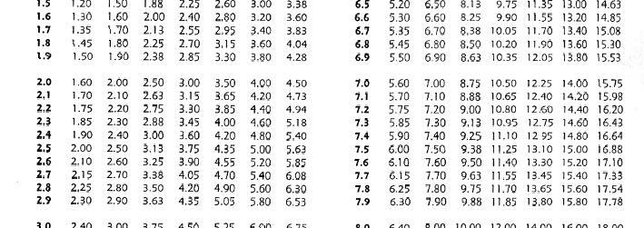
3 Model "97" Hudson Country Club Custom Eight Series 129 inch wheelbase Starting car and engine number Model "98" Hudson Business Cars Big Boy Series 1 19 inch wheelbase Starting car and engine number Model "40 T" Hudson Six Traveler Series 113 inch wheelbase Starting car and engine number Model "40 P" Hudson Six DeLuxe Models 113 inch wheelbase Starting car and engine number Model "41" Hudson Super Six Models 1 18 inch wheelbase Starting car and engine number Model "43" Hudson Country Club Six Models 125 inch wheelbase Starting car and engine number Model "44" Hudson Eight Models 118 inch wheelbase Starting car and engine number Model "47" Hudson Country Club Eight Models 125 inch wheelbase Starting car and engine number Model "10C" Hudson Six Business Cars 116 inch wheelbase Starting car and engine number C10101 Model "10T" Hudson Six Traveler Series 116 inch wheelbase Starting car and engine number T10101 Model "10P" Hudson Six DeLuxe Series 116 inch wheelbase Starting car and engine number P10101 Model "11" Hudson Super Six Series 121 inch wheelbase Starting car and engine number Model "12" Hudson Commodore Six Series 121 inch wheelbase Starting car and engine number Model "14" Hudson Commodore Eight Series 121 inch wheelbase Starting car and engine number Model "15" Hudson Commodore Eight DeLuxe Series 121 inch wheelbase Starting car and engine number Model "17" Hudson Commodore Eight Custom Series 128 inch wheelbase Starting car and engine number Model "18" Hudson Six Big Boy Series 128 inch wheelbase Starting car and engine number Model "20C" Hudson Six Business Cars 1 16 inch wheelbase Starting car and engine number C20101 Model "20T" Hudson Six Series 1 16 inch wheelbase Starting car and engine number T Model "20P" Hudson Six DeLuxe Series 116 inch wheelbase Starting car and engine number P20101 Model "21" Hudson Super Six Series 121 inch wheelbase Starting car and engine number Model "22" Hudson Commodore Six Series 121 inch wheelbase Starting car and engine number Model "24" Hudson Commodore Eight Series 121 inch wheel base. Starting car and engine number Model "25" Hudson Commodore Eight DeLuxe Series 121 inch wheelbase. Starting car and engine number Model "27" Hudson Commodore Eight Custom Series 128 inch wheelbase. Starting car and engine number Model "28" Hudson Six Big Boy Series 128 inch wheelbase Starting car and engine number This manual is designed as an aid to the service salesman in quickly and accurately quoting standard prices for the repair operations necessary in servicing Hudson built cars. The flat rate time as given applies to cars carrying standard equipment. Where the installation of accessories such as heaters and radios causes interference, it will be necessary to add to these figures to compensate for the additional labor involved. INSTRUCTIONS In this edition of the Flat Rate Manual group and operation numbers are used to identify each service operation. These appear in the left hand column, the first digits representing the group number and the remainder the operation number. The flat rate time is shown in the right column in hours and tenths opposite each operation. To facilitate pricing the operations in this book, a labor charge conversion table is furnished on which labor charges have been computed on the basis of rates of $0.80, $1.00, $1.25, $1.50, $1.75, $2.00 and $2.25 per hour. When you have determined which of these hourly rates is suitable for your requirements transpose the price given in the corresponding column of the conversion table opposite the number of hours required for the job, to the labor column on the right hand side of each page. This may be done with pen and ink. II
4 III
5 IV
6 V
7 VI

8 Page 1 OPERATION DESCRIPTION PRICE FRONT AXLE AXLE ASSEMBLY Inspect axle and Steering. A thorough inspection of axle, steering gear, drag link, torque arm grommets, wheels and tires. Includes checking caster, camber and toe in models 89, 90, 98-Less torque arm bushings 91, 92, 93, 95, 97 AXLE ASSEMBLY Remove and install. Includes adjusting brakes and aligning front wheels models 89, 90, 98 91, 92, 93, 95, 97 AXLE CENTER Remove and install I beam only. Includes adjusting brakes, aligning wheels and setting caster models 89, 90, 98 91, 92, 93, 95,
9 2 OPERATION DESCRIPTION PRICE FRONT AXLE Continued AXLE CENTER Straighten. Remove axle, straighten, reassemble and install. Adjust brakes and align front wheels models 89, 90, 98 91, 92, 93, 95, 97 AXLE CENTER Rebush. Renew and install spindle pivot pin bushings, spindle pivot pins and thrust balls if necessary. One side Both sides AXLE CENTER Remove and install expansion plug. One side Both sides AXLE TO FRAME TORQUE ARM Remove and install. Includes checking and set ting caster. 91, 92, 93, 95, 97 One side Both sides TORQUE ARM FRAME BRACKET BOLT Remove and install. 91, 92, 93, 95, 97 TORQUE ARM RUBBER GROMMETS Remove and install. 91, 92, 93, 95, 97 TORQUE ARM BOLT (UPPER) Remove and install. 91, 92, 93, 95, 97 One side Both sides TORQUE ARM BOLT (Lower) Remove and install. 91, 92, 93, 95, 97 One side Both sides SPRING SEAT AND CAP ASSEMBLY Remove and install. 91, 92, 93, 95, 97 One side CASTER Reset. Includes checking the caster, removing or installing necessary shims and aligning wheels. Set steering on high point models SPINDLES AND STEERING ARMS SPINDLE Remove and install spindle, spindle pivot pin or thrust bearing. One side Both sides 1939, One side Both sides
10 OPERATION DESCRIPTION PRICE 3 SPINDLES AND STEERING ARMS Continued STEERING ARM Remove and install. Includes adjusting toe in. Right side Left side Either side STEERING ARM Tighten. TIE ROD TIE ROD ASSEMBLY Remove and install Includes adjusting toe in. TIE ROD ASSEMBLY Remove and install (One rod assembly only) Includes adjusting toe in. TIE ROD Remove and install Includes adjusting toe in. TIE ROD Remove and install Includes adjusting toe in. One Both TIE ROD CLAMP Remove and install. One side Both sides Both on one side Both on both sides TIE ROD Adjust for toe in with aligning tool or fixture. TIE ROD END ASSEMBLY Remove and install Includes adjusting toe in. One side Both sides Both on one side Both on both sides

11 4 OPERATION DESCRIPTION PRICE FRONT END SUSPENSION CASTER, CAMBER AND TOE IN Check. Cancel if adjustment is authorized. CASTER, CAMBER AND TOE IN Adjust. FRONT WHEEL TOE IN Adjust STEERING SPINDLE PIVOT PIN Remove and install bushings. caster, camber and toe in. One side Both sides Includes adjusting STEERING SPINDLE SUPPORT Remove and install. camber and toe in. One side Both sides Includes adjusting caster, LOWER SUPPORT ARM OUTER PIVOT PIN AND/OR BUSHING Remove and install. Includes adjusting caster, camber and toe in. One side Both sides
12 OPERATION DESCRIPTION PRICE 5 FRONT END SUSPENSION Continued LOWER SUPPORT ARM PIVOT BUSHINGS Remove and install. Front and rear. One side Both sides LOWER SUPPORT ARM PIVOT Remove and install. Includes adjusting caster, camber and toe in. One side Both sides LOWER SUPPORT ARM Remove and install. Includes adjusting caster, camber and toe in. ECCENTRIC BUSHING Remove and install. Includes adjusting caster, camber and toe in. One side Both sides UPPER SUPPORT ARM AND PIVOT ASSEMBLY Remove and install. Includes adjusting caster, camber and toe in. One side Both sides UPPER SUPPORT ARM BUSHINGS Remove and install. Front and rear. One side Both sides FRONT SUSPENSION Overhaul. Includes rebushing steering spindle supports, re placing any bushings or parts necessary, complete caster, camber and toe in correction. Does not include any work on brakes. FRONT SUSPENSION COMPLETE Remove and install. Includes adjust. One side Both sides CENTER STEERING ARM Tighten to Frame Support. CENTER STEERING ARM Remove and install. 6 cylinder BEARING FOR CENTER STEERING ARM WITH ARM REMOVED Remove and install
13 6 OPERATION DESCRIPTION PRICE FRONT SPRINGS, FRONT SHOCK ABSORBERS AND AUTO POISE REAR SHOCK ABSORBERS LISTED IN GROUP 20 REAR SPRINGS LISTED IN GROUP FRONT COIL SPRING Remove and install. RUBBER SPRING SILENCER Remove and install. SPRING SPACER Install. REBOUND BUMPERS Remove and install. Each FRONT SHOCK ABSORBER Remove and install one. FRONT SHOCK ABSORBERS Remove and install both. VALVES FOR TWO FRONT SHOCK ABSORBERS Remove and install. FRONT SHOCK ABSORBER ANCHOR PLATE Remove and install. One Both FRONT SHOCK ABSORBER RUBBER BUSHINGS Remove and install. One shock Both shocks TORSION BAR Remove and install. TORSION BAR MOUNTING BRACKET Remove and install. One side Both sides TORSION BAR RUBBER BUSHINGS Remove and install. One side TORSION BAR CONNECTOR AND/OR RUBBER CUSHIONS Remove and install One side Both sides TORSION BAR CONNECTOR BRACKET Remove and install
14 OPERATION DESCRIPTION PRICE 7 FRONT HUBS AND BEARINGS (SEE GROUP 3 FOR WHEELS AND HUBS) INNER BEARING COMPLETE WITH GREASE WASHER AND RETAINER ASSEM BLY OR OUTER BEARING AND SPINDLE WASHER Remove and install. Includes cleaning and adjusting. One wheel Both wheels HUB AND BRAKE DRUM ASSEMBLY Remove and install. Includes cleaning and adjusting wheel bearings. One wheel FRONT WHEEL BEARINGS Adjust only. Both wheels DRAG LINK DRAG LINK ASSEMBLY Remove and install. DRAG LINK Adjust. For wheels straight ahead with steering gear on high point. DRAG LINK BALL SEAT AND/OR SPRING, ONE END Remove and install. DUST COVER Remove and install

15 8 OPERATION DESCRIPTION PRICE REAR AXLE AXLE ASSEMBLY Remove and install complete unit. Includes bleeding lines and adjusting brakes. AXLE HOUSING Remove and install. Remove axle, disassemble, replace hous ing, build up and install. Includes bleeding lines and adjusting brakes DRIVE SHAFTS, BEARINGS AND OIL SEALS DRIVE SHAFT Remove and install one. Remove one wheel only, replace shaft and reassemble. DRIVE SHAFT Adjust end play one side only. Adjust and equalize both sides. DRIVE SHAFT THRUST BUTTON Remove and install one when shaft is out
16 OPERATION DESCRIPTION PRICE 9 DRIVE SHAFTS, BEARINGS AND OIL SEALS Continued DRIVE SHAFT OIL SEAL (Inner) Remove and install. Clean oil off brakes and brake drums. One side Both sides Inner and Outer One side Both sides When hubs are off (Inner and Outer) One side Both sides REAR WHEEL BEARINGS Remove and install. One side Both sides With hubs removed One side Both sides DIFFERENTIAL CARRIER AND GEAR SET CARRIER AND GEAR SET ASSEMBLY OR CARRIER HOUSING GASKET Re move and install. GEARS Inspect. Remove carrier, disassemble. Inspect thoroughly, build up and replace. Clean and refill case. CARRIER AND GEAR SET ASSEMBLY Overhaul. Includes removing and install ing the carrier assembly and completely disassembling and replacing all the necessary parts and adjusting the drive gear and pinion mesh. DIFFERENTIAL BEARINGS Remove and install both bearings. DRIVE GEAR BOLTS AND LOCKS Remove and install. DRIVE GEAR Remove and install drive gear only. DRIVE PINION AND PINION BEARINGS Remove and install drive pinion or pinion bearings. DRIVE GEAR AND PINION Remove and install both
17 10 OPERATION DESCRIPTION PRICE DIFFERENTIAL CARRIER AND GEAR SET Continued DRIVE GEAR AND PINION Adjust. mesh and replace. DRIVE PINION OIL SEAL Remove and install. Remove carrier, adjust gear and pinion DIFFERENTIAL CARRIER FLANGE BOLTS Remove and install. DIFFERENTIAL CARRIER BUMPER Remove and install. 1938, 1939, DRIVE PINION COMPANION FLANGE Remove and install WHEELS WHEEL Remove and install. Includes removing and replacing tire. One wheel Five wheels FRONT WHEELS Align. Adjust tie rod for correct toe in using aligning fixture. FRONT WHEEL BEARINGS Adjust only. both wheels FRONT WHEEL BEARINGS Adjust bearings and align wheels. FRONT WHEEL BEARINGS Remove and install one cone and roll (inner or outer). One wheel Both wheels BEARING CUP Remove and install. Add each. GREASE WASHER Remove and install. One wheel Both wheels FRONT HUB AND BRAKE DRUM ASSEMBLY Remove and install. No brake adjustment included. One front wheel REAR HUB AND BRAKE DRUM ASSEMBLY Remove and install. No brake adjustment included. One wheel REAR HUB KEY Remove and install one rear hub key only. WHEELS Tighten. Remove hub caps and pull up drive shaft nuts with socket wrench. Both sides WHEELS BALANCE. Includes remove and install wheels. Does not include changing tires. Two statically Two statically and dynamically
18 11
19 12
20 13
21 14 OPERATION DESCRIPTION PRICE BRAKES BRAKES Adjust. Service adjustment only. Adjust pedal clearance and refill master cylinder if necessary. BRAKES Adjust. Major adjustment. Remove wheels, reset eccentrics (on models where used) and star wheels, adjust anchor pins, tighten spring clips, and refill master cylinder if necessary. BRAKES Adjust and free up. Remove wheels, remove shoes, free up all joints and make major adjustment and tighten spring clips. Check fluid in master cylinder, refill if necessary. BRAKES Bleed lines. Bleed lines and master cylinder. BRAKES Flush System. Flush entire system and master cylinder with alcohol and refill with new fluid. Check for leaks. BRAKES Check System. Check system for leaks using pressure gauge on wheel cylinders. BRAKE PEDAL Adjust for proper clearance A BRAKE SHOES BRAKE SHOES Remove and install all shoes and adjust brakes. Use this opera tion for installing new or relined shoes. 1938, 1939, One wheel Four wheels 1941, One wheel Four wheels BRAKE SHOES Reline. Add each wheel B BRAKE DRUM Install (rivet to hub). Add each wheel.. 4-8C 4-9 If necessary to bleed lines add operation 4-4. BRAKE SHOES Lubricate. Remove wheels, apply special lubricant between shoes and backing plate. Four wheels
22 15


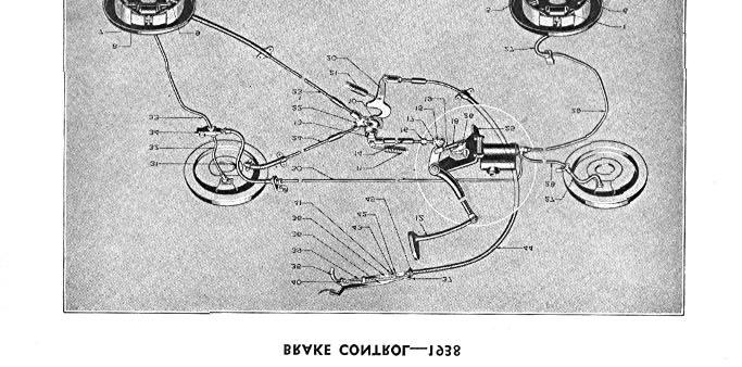
23 16 OPERATION DESCRIPTION PRICE BRAKE SHOES Continued BRAKE BACKING PLATE Remove and install. Includes removing and installing all necessary parts and bleeding the lines. 1938, 1939, One front One rear 1941, One front One rear BRAKE DRUM Remove and install one drum only. BRAKE DRUM Reface on machine when wheel is removed. One Two Four CABLES AND RODS CABLE ASSEMBLY OR CONDUIT Remove and install. One rear Both rear BRAKE CONTROL LEVER Remove and install. CONTROL LEVER BRACKET AND PIVOT PIN Remove and install. PUSH ROD Remove and install
24 OPERATION DESCRIPTION PRICE 17 CABLES AND RODS Continued PUSH ROD ADJUSTABLE END Remove and install. ADJUST PUSH ROD Adjust to proper clearance between push rod and lock nuts. MASTER CYLINDER MASTER CYLINDER Remove and install and bleed lines. MASTER CYLINDER OVERHAUL Remove and install. Replace all necessary parts and bleed lines. MASTER CYLINDER OPERATING LEVER Remove and install. MASTER CYLINDER PUSH ROD Remove and install. MASTER CYLINDER OUTLET FITTING OR GASKET Remove and install. If necessary to bleed lines add operation 4-4. MASTER CYLINDER FILLER CAP OR GASKET Remove and install WHEEL CYLINDER WHEEL CYLINDER Remove and install and bleed lines. One front Both front One rear Both rear All WHEEL CYLINDER Overhaul. Remove and install and replace all necessary parts, bleed lines. Front or rear WHEEL CYLINDER BLEEDER VALVE Remove and install. WHEEL CYLINDER TUBE FITTING OR GASKET Remove and install and bleed lines
25 18 OPERATION DESCRIPTION PRICE HOSES AND TUBES BRAKE HOSE Remove and install one and bleed lines. BRAKE TUBES Remove and install all and bleed lines. Master Cylinder to left front brake hose. to car No Master Cylinder to Frame Tee. after car No. 4557, 1939, Frame Tee to left front brake hose. after car No. 4557, 1939, Frame Tee to right front brake hose. after car No. 4557, 1939, Master Cylinder to right front brake hose. to car No Master Cylinder to rear hose. Frame Tee to Rear Axle Tee. 1939, Rear axle tee to right rear wheel cylinder. Rear axle tee to left rear wheel cylinder. FRAME TEE Remove and install. REAR AXLE TEE Remove and install and bleed lines HILL HOLD 4-42 Install Hill Hold Kit on cars not equipped at factory. adjusting. to car No after car No , Includes bleeding lines and 3 2 2


26 19 OPERATION DESCRIPTION PRICE HILL HOLD Continued HILL HOLD ASSEMBLY Remove and install and adjust. HILL HOLD Overhaul. Includes removing and installing hill hold assembly, com letely disassembling and replacing any necessary parts, bleeding lines and readjusting. HILL HOLD Adjust. Check and adjust lever and adjust the operating rod. HILL HOLD TO MASTER CYLINDER MOUNTING BOLT Remove and install mounting fitting, bolt or gaskets.. Includes bleeding lines and adjusting. HILL HOLD OUTLET FITTING Remove and install outlet fitting, fitting bolt or gaskets. Includes bleeding lines and adjusting. VALVE ROD Remove and install operating valve rod, rodspring or connector and adjust. HILL HOLD BRAKE TUBE Remove and install Hill Hold to Frame Tee. Includes bleeding lines


27 20 CLUTCH OPERATION DESCRIPTION PRICE CLUTCH CLUTCH Drain and refill. CLUTCH Wash out and refill. CLUTCH PEDAL Adjust clutch pedal. CLUTCH Inspect. Remove clutch assembly and inspect. Build up as removed if no repairs are authorized. NOTE: When a definite diagnosis cannot be made it is advisable to quote this operation. Advise owner when clutch is disassembled, giving price of labor and material necessary. Without Electric Hand With Electric Hand with overdrive 1941, 1941, with overdrive with Drive-Master with Drive-Master and overdrive
28 OPERATION DESCRIPTION PRICE 21 CLUTCH Continued CLUTCH ASSEMBLY Remove and install. Includes replacing the clutch cover gasket or driving plate. Without Electric Hand With Electric Hand with overdrive 1941, 1941, with overdrive with Drive-Master with Drive-Master and overdrive PILOT BEARING Remove and install in flywheel. Without Electric Hand With Electric Hand with overdrive 1941, 1941, with overdrive with Drive-Master with Drive-Master and overdrive CLUTCH ASSEMBLY Overhaul. Includes removing and installing the clutch assembly and replacing any parts necessary such as the pressure plate, retainer, fingers, engaging springs or clutch cover. Without Electric Hand With Electric Hand 1939 models Without Electric Hand With Electric Hand with overdrive 1941, 1941, with overdrive with Drive-Master with Drive-Master and overdrive CLUTCH HOUSING Remove and install. Without Electric Hand With Electric Hand with overdrive 1941, 1941, with overdrive with Drive-Master with Drive-Master and overdrive THROWOUT COLLAR Remove and install and 1939 models Without Electric Hand With Electric Hand with overdrive 1941, 1941, with overdrive with Drive-Master with Drive-Master and overdrive When drive gear bearing retainer is replaced, add
29 22 OPERATION DESCRIPTION PRICE CLUTCH Continued THROWOUT BEARING OR OIL SEAL Remove and install. Without Electric Hand With Electric Hand with overdrive 1941, 1941, with overdrive with Drive-Master with Drive-Master and overdrive THROWOUT YOKE Remove and install. Without Electric Hand With Electric Hand with overdrive 1941, 1941, with overdrive with Drive-Master with Drive-Master and overdrive VACUMOTIVE DRIVE VACUMOTIVE DRIVE Install on cars not equipped at factory POWER CYLINDER ASSEMBLY Removeand install. Includes adjusting VACUMOTIVE DRIVE Overhaul. Includes removing the power cylinder assembly, completely disassembling, installing and adjusting. VACUMOTIVE DRIVE Adjust and lubricate. INSTRUMENT PANEL SWITCH Remove and install. SHIFT RAIL SWITCH Remove and install. Includes removing and installing floor boards. GOVERNOR SWITCH Remove and install
30 OPERATION DESCRIPTION PRICE 23 VACUMOTIVE DRIVE Continued 5-19 ACCELERATOR SWITCH Remove and install WIRING HARNESS, UPPER OR LOWER Remove and install. and installing floor boards. Includes removing MOUNTING BRACKET Remove and install BELL CRANK MOUNTING BRACKET Remove and install. Includes draining and refilling radiator SOLENOID VALVE, HOUSING OR GASKET Remove and install. SOLENOID Remove and install. BELL CRANK Remove and install. VALVE LEVER Remove and install. LEVER TRUNNION LINK Remove and install. VALVE LEVER CAM Remove and install. VALVE AND VALVE ROD ASSEMBLY Remove and install. CAM LEVER SLEEVE OR ROD ASSEMBLY Remove and install. CAM LEVER SLEEVE ROD BELL CRANK Remove and install. BELL CRANK TO COUPLING LEVER ROD OR PLAY LINK Remove and install. TRIP LEVER Remove and install
31 24 OPERATION DESCRIPTION PRICE VACUMOTIVE CLUTCH CONTROL Continued TRIP LEVER SPRING Remove and install. COMPENSATOR LEVER ASSEMBLY Remove and install. PISTON ROD BOOT Remove and install. VACUUM TUBES Remove and install. VACUUM TUBE COUPLING HOSE Remove and install. VACUUM TUBE FITTING, POWER CYLINDER OR MANIFOLD FITTING Remove and install.,.4...
32 25
33 26
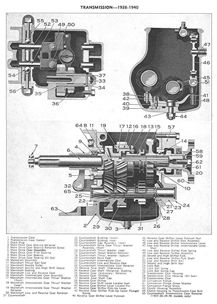
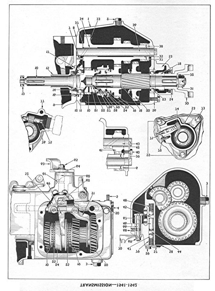
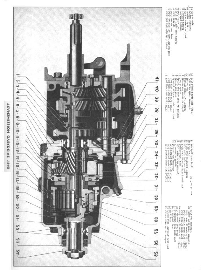
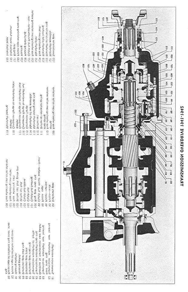
34 27 1 Transmission Case 2 Drain Plug 3 Filler Plug 4 Shift Rail Opening Expansion Plug 5 Transmission Case Stud (left side at rear) 6 Countershaft Gear Cluster Bronze Thrust Washer, Rear Pin 7 Countershaft Gear Cluster Bronze Thrust Washer, Front Pin 8 Transmission Case Gasket, Front 9 Clutch Housing 10 Main Drive Gear Assembly 11 Main Drive Gear Bearing 12 Main Drive Gear Lock Ring 13 Main Drive Gear Pilot Bearing 14 Main Drive Gear Oil Seal 15 Main Drive Gear Bearing Retainer 16 Main Drive Gear Bearing Retainer Locating Pin 17 Main Drive Gear Bearing Retainer Gasket 18 Main Shaft 19 Main Shaft Intermediate Gear 20 Main Shaft Low and Reverse Gear 21 Main Shaft Needle Roller Pilot Bearing 22 Main Shaft Needle Roller Retainer 23 Main Shaft Rear Bearing 24 Synchronizer Shift Sleeve 25 Synchronizer Ring TRANSMISSION Synchronizer Shift Sleeve Hub 27 Synchronizer Shift Sleeve Hub Lock Ring 28 Synchronizer Spring 29 Synchronizer Shift Plate 30 Companion Flange 31 Companion Flange Nut 32 Companion Flange Washer 33 Countershaft Gear Cluster 34 Countershaft Gear Cluster Bushing, Front 35 Countershaft Gear Cluster Bushing, Rear 36 Countershaft 37 Countershaft Gear Cluster Bronze Washer 38 Countershaft Gear Cluster Steel Washer 39 Countershaft and Reverse Shaft Lock Plate 40 Countershaft and Reverse Shaft Lock Plate Screw 41 Reverse Idler Gear 42 Reverse Idler Gear Bushing 43 Reverse Idler Gear Shaft 44 Low and Reverse Shift Rail 45 Second and High Shift Rail 46 Shift Rail Interlock 47 Shift Rail Lock Ball 48 Shift Rail Lock Ball Spring (High and Intermediate) 49 Second and High Shift Fork 50 Breather 51 Low and Reverse Shift Fork 52 Low and Reverse Shifter 53 Gear Housing 54 Gear Housing Oil Seal 55 Gear Housing Bolt 56 Gear Housing Gasket 57 Transmission Cover 58 Cover Gasket 59 Cover Bolt 60 Shift Shaft 61 Shift Shaft Pin 62 Shift Shaft Lever Inner 63 Shift Shaft Lever Outer 64 Shift Shaft Seal 65 Shift Shaft Nut 66 Shift Selector Lever and Shaft 67 Shift Selector Shaft Bushing 68 Shift Selector Shaft Bushing Set Screw 69 Shift Selector Shaft Nut 70 Shift Selector Lever Outer 71 Speedometer Cable 72 Speedometer Cable Screw 73 Gear Housing Bolt 74 Speedometer Pinion 75 Governor Pinion Lock Ring 76 Governor Pinion 77 Gear Housing 78 Speedometer Gear 79 Shift Rail Lock Ball Spring (Low and Reverse) OPERATION DESCRIPTION PRICE TRANSMISSION TRANSMISSION ASSEMBLY Remove and install. Without Electric Hand With Electric Hand wtih overdrive 1941, 1941, with overdrive with Drive-Master with Drive-Master and overdrive TRANSMISSION ASSEMBLY Overhaul. Includes removing and installing, com pletely disassembling, replacing any necessary parts and reassembling. Without Electric Hand With Electric Hand with overdrive 1941, 1941, with overdrive with Drive-Master with Drive-Master and overdrive TRANSMISSION CASE Remove and install. Without Electric Hand With Electric Hand with overdrive 1941, 1941, with overdrive with Drive-Master with Drive-Master and overdrive
35 28 OPERATION DESCRIPTION PRICE MAIN SHAFT GROUP MAIN SHAFT END PLAY Adjust. Without Electric Hand With Electric Hand MAIN SHAFT Remove and install main shaft or any necessary parts in the main shaft group including the thrust balls, needle rollers, second and high shift sleeve, low and reverse gear, low and reverse gear retainer or main shaft rear bearing. Without Electric Hand With Electric Hand with overdrive MAIN SHAFT Remove and install main shaft or any necessary parts on the main shaft including the second and high shift fork or shaft, low and reverse shift fork or shaft, low and reverse shifter, synchronizer assembly, intermediate gear or low and reverse gear or main shaft rear bearing. 1941, 1941, with overdrive with Drive-Master with Drive-Master and overdrive MAIN SHAFT INTERMEDIATE GEAR Remove and install main shaft intermediate gear assembly and replace any necessary parts including the main shaft intermediate gear retainer or intermediate gear thrust washers. Without Electric Hand With Electric Hand with overdrive TRANSMISSION MAIN SHAFT COMPANION FLANGE Remove and install MAIN SHAFT DRIVE GEAR Remove and and install. all parts including the main shaft intermediate gear. Without Electric Hand With Electric Hand with overdrive Includes replacing any or MAIN DRIVE GEAR Remove and install. Includes replacing any or all parts in cluding needle rollers or main drive gear bearing. 1941, 1941, with overdrive with Drive-Master with Drive-Master and overdrive
36 OPERATION DESCRIPTION PRICE MAIN SHAFT GROUP Continued MAIN SHAFT DRIVE GEAR BEARING Remove and install. Including drive gear bearing retainer, drive gear bearing retainer oil seal. Without Electric Hand With Electric Hand with overdrive MAIN DRIVE GEAR BEARING RETAINER OR OIL SEAL Remove and install. 1941, 1941, with overdrive with Drive-Master with Drive-Master and overdrive MAIN SHAFT DRIVE GEAR PILOT BEARING Remove and install. Without Electric Hand With Electric Hand with overdrive 1941, 1941, with overdrive with Drive-Master with Drive-Master and overdrive COUNTERSHAFT GROUP COUNTERSHAFT Adjust end play. 1938, 1939, with overdrive COUNTERSHAFT Remove and install. Includes removing and installing the countershaft drive gear, low and reverse gear, intermediate gear, thrust washers or retainers. Without Electric Hand With Electric Hand with overdrive COUNTERSHAFT GEAR CLUSTER Remove and install. Includes replacing coun ter shaft or thrust washers. 1941, 1941, with overdrive with Drive-Master with Drive-Master and overdrive COUNTERSHAFT BUSHINGS ( Both) Remove and install and line ream. Without Electric Hand With Electric Hand with overdrive
37 30 OPERATION DESCRIPTION PRICE COUNTERSHAFT GROUP Continued COUNTERSHAFT GEAR CLUSTER BUSHINGS Remove and install and line ream. 1941, 1941, with overdrive with Drive-Master with Drive-Master and overdrive COUNTERSHAFT THRUST WASHER DOWEL PIN Replace. 1941, 1941, with overdrive with Drive-Master with Drive-Master and overdrive COUNTERSHAFT FRONT BEARING Remove and install front bearing or expan sion plug. Without Electric Hand With Electric Hand with overdrive COUNTERSHAFT REAR BEARING CAP Remove and install bearing cap, bearing cap gasket or expansion plug. 1938, 1939, with overdrive COUNTERSHAFT REAR THRUST WASHER, RETAINER, OR THRUST WASHER SPACER Remove and install. 1938, 1939, with overdrive REVERSE GEARS REVERSE GEARS Remove and install reverse gear and rotating shaft assembly. Includes removing and installing the reverse gear stationary shaft and reverse gear sliding gear. Without Electric Hand With Electric Hand with overdrive REVERSE GEAR SHIFTER Remove and install. Includes removing and installing the shifter lever, pick up lever, shifting lever fulcrum, pick up lever plunger or spring. Without Electric Hand With Electric Hand with overdrive REVERSE GEAR SHAFT CAP OR CAP GASKET Remove and install. 1938, 1939, with overdrive
38 OPERATION DESCRIPTION PRICE 31 REVERSE GEARS Continued REVERSE IDLER GEAR OR SHAFT Remove and replace. 1941, 1941, with overdrive with Drive-Master with Drive-Master and overdrive REVERSE IDLER GEAR BUSHING Remove and install and ream. 1941, 1941, with overdrive with Drive-Master with Drive-Master and overdrive SPEEDOMETER GEAR HOUSING SPEEDOMETER GEAR HOUSING Remove and install. stalling speedometer drive gear, housing gasket or oil seal. SPEEDOMETER PINION OR PINION SLEEVE Remove and install. Includes removing and in SHIFT RAILS SHIFT RAILS Remove and install low and reverse shift rail or shifter assembly, second and high shift rail or shifter fork. with overdrive LOW AND REVERSE INTERMEDIATE LEVER OR LEVER STUD Remove and install. with overdrive LOW AND REVERSE SHIFTER FORK ASSEMBLY OR SHIFTER FORK SHAFT Remove and install. Without Electric Hand With Electric Hand with overdrive HIGH AND INTERMEDIATE SHIFT RAIL OR SHIFT FORK Remove and install. 1941, 1941, with overdrive with Drive-Master with Drive-Master and overdrive
39 32 OPERATION DESCRIPTION PRICE SHIFT RAILS Continued LOW AND REVERSE SHIFT RAIL, SHIFT RAIL FORK OR SHIFTER Remove and install. 1941, 1941, with overdrive with Drive-Master with Drive-Master and overdrive SHIFT RAIL LOCK BALL, LOCK BALL CAP, LOCK BALL SPRING, LOCK BALL PLUNGER FOR LOW AND REVERSE 0 R SECOND AND HIGH Remove and replace. 1938, 1939, TRANSMISSION SHIFT SHAFT Remove and install. 1941, 1941, with overdrive with Drive-Master with Drive-Master and overdrive TRANSMISSION SHIFT SELECTOR LEVER AND SHAFT Remove and install. 1941, 1941, with overdrive with Drive-Master with Drive-Master and overdrive TRANSMISSION SHIFT LOCK Install. 1941, TRANSMISSION SHIFT LOCK Remove and install. 1941, CONTROL LEVER TRANSMISSION CONTROL COVER OR CONTROL COVER GASKET Remove and install. 1939, TRANSMISSION COVER OR COVER GASKET Remove and install. 1941, TRANSMISSION CONTROL COVER Overhaul. Includes removing and installing the control lever assembly, fulcrum oil seal, fulcrum spring, or fulcrum washer. 1939, HANDY SHIFT CONTROL LEVER Remove and install. 1939, CONTROL LEVER FULCRUM BRACKET Remove and install. 1939, CONTROL LEVER TUBE UPPER BRACKET Remove and install. 1939,
40
41
42 OPERATION DESCRIPTION PRICE 35 CONTROL LEVER Continued CONTROL LEVER TUBE LOWER BRACKET Remove and install. 1939, CONTROL WIRE CASING AND BRACKET ASSEMBLY Remove and install. 1939, CONTROL TUBE TO TRANSMISSION COVER ROD ASSEMBLY Remove and install. 1939, CONTROL TUBE TO TRANSMISSION SHIFT SHAFT LEVER OUTER Remove and install. 1941, REMOTE CONTROL LEVER PUSH ROD Remove and install. 1939, HUDSON Drive-Master 6-51 Drive-Master Service Check up. Includes the following: Inspect and tighten power unit assembly mounting and mounting bracket. Inspect and tighten vacuum and intake tube connections. Inspect and tighten all rod clips and connections. Check all electrical and ground connections and test circuits with test lamp if necessary POWER UNIT ASSEMBLY POWER UNIT ASSEMBLY Remove and install. MOUNTING BRACKET Remove and install. MOUNTING STUD RUBBER SPACER Remove and install. MOUNTING STUD RUBBER WASHER Remove and install. VACUUM OR INTAKE TUBES Remove and install one. TUBE COUPLING HOSE Remove and install one. TUBE UNION Remove and install one
43 36 OPERATION DESCRIPTION PRICE ROD, LEVERS AND OPERATING PARTS ROD (Transfer diaphragm to transfer key) Remove and install. ROD END (Transfer diaphragm to transfer key) Remove and install. ROD SLEEVE (Transfer diaphragm to transfer key) Remove and install. ROD RUBBER BOOT (Transfer diaphragm to transfer key) Remove and install. ROD (Power shift cylinder to selector lever) Remove and install. ROD RUBBER BOOT (Power shift cylinder to selector lever) Remove and install HAND SHIFT SHAFT LEVER Remove and install. POWER SHIFT SHAFT LEVER Remove and install. TRANSMISSION SHIFT SHAFT TRANSFER KEY Remove and install. TRANSMISSION SHIFT SHAFT TRANSFER KEY HUB Remove and install. TRANSMISSION SHIFT SHAFT TRANSFER KEY TO HUB PIN Remove and install. TRANSMISSION SHIFT SHAFT TRANSFER KEY HUB LOCK SCREW Tighten or replace. TRANSMISSION CLUTCH SWITCH OPERATING ROD Remove and install. TRANSMISSION NEUTRAL AND LIMIT SWITCH OPERATING ROD Remove and install. TRANSMISSION TRANSFER SWITCH OPERATING ROD Remove and install. TRANSMISSION SELECTOR SWITCH OPERATING ROD Remove and install
44 OPERATION DESCRIPTION PRICE 37 SWITCHES AND WIRING 6-75 TRANSMISSION SHIFT RAIL SWITCH Remove and install TRANSMISSION SWITCH ASSEMBLY Remove and install GOVERNOR SWITCH ASSEMBLY Remove and install GOVERNOR SWITCH PINION Remove and install INSTRUMENT PANEL SWITCH Remove and install WIRING HARNESS (Upper Instrument Panel) Remove and install WIRING HARNESS (Lower) Remove and install POWER UNIT ASSEMBLY GROUND WIRE Remove and install CIRCUIT BREAKER AND FUSE BLOCK ASSEMBLY Remove and install OVERDRIVE 6-84 TRANSMISSION AND OVERDRIVE ASSEMBLY Remove and install. 1941, with Drive-Master 6-85 TRANSMISSION AND OVERDRIVE Remove, inspect, and replace. Cancel if overhaul is authorized. 1941, with Drive-Master 6-86 TRANSMISSION AND OVERDRIVE Overhaul. 1941, with Drive-Master 6-87 OVERDRIVE ASSEMBLY Overhaul. Includes complete disassembly and replacement of any necessary parts and reassembling. 1941, with Drive-Master
45 38 OPERATION DESCRIPTION PRICE OVERDRIVE Continued 6-88 OVERDRIVE UNIT ASSEMBLY Remove and install. with Drive-Master OVERDRIVE REAR BEARING Remove and install. with Drive-Master OVERDRIVE REAR BEARING OIL SEAL Remove and install. with Drive-Master OVERDRIVE MAIN SHAFT OR CLUTCH SLEEVE Remove and install. with Drive-Master OVERDRIVE SHIFT RAIL FORK OR LOCK UP PLUNGER Remove and install. 1941, with Drive-Master OVERDRIVE SOLENOID Remove and install. Includes replacement of gaskets SOLENOID OPERATED LEVERS OR TOGGLE Remove and install. 1941, with Drive-Master SOLENOID GEAR PAWL Remove and install. with Drive-Master OVERDRIVE SOLENOID THROTTLE SWITCH Remove and install and adjust OVERDRIVE GOVERNOR SWITCH Remove and install. 1941, 6-98 OVERDRIVE SOLENOID WIRING HARNESS ASSEMBLY Remove and install OVERDRIVE CONTROL WIRE ASSEMBLY Remove and install and adjust OVERDRIVE SUPPORT MEMBER ASSEMBLY Remove and install SPEEDOMETER DRIVE GEAR Remove and install. with Drive-Master
46 OPERATION DESCRIPTION PRICE 39 OVERDRIVE Continued SPEEDOMETER DRIVE PINION OR SLEEVE Remove and install. 1941, ADAPTER TO TRANSMISSION GASKET Remove and install. 1941, with Drive-Master. ADAPTER TO HOUSING GASKET Remove and install. with Drive-Master TRANSMISSION MAIN SHAFT OR MAIN SHAFT REAR BEARING Remove and install. with Drive-Master OVERDRIVE RELAY SWITCH. FREE WHEELING CAM ASSEMBLY Remove and install. with Drive-Master OVERDRIVE CLUTCH PAWL AND CORE ASSEMBLY Remove and install. Includes replacement of pawl and core, pawl springs or pinion cage assembly Includes replace- OVERDRIVE PINION CAGE ASSEMBLY Remove and install. ment of ring gear or drive gear or bushing. 1941, with Drive-Master HOUSING ADAPTER Remove and install. with Drive-Master OVERDRIVE STATIONARY GEAR OR BALK RING Remove and install. with Drive-Master INTERLOCK LEVER OR INTERLOCK PLUNGER Remove and install. 1941, with Drive-Master
47 40
48 OPERATION DESCRIPTION PRICE 41 ELECTRIC HAND ADJUST ELECTRIC HAND Using Electric Hand Service Test Kit, check operation of the selector switch, clutch circuit breaker switch, cross shift switch, neutral switch, interlock switch, transmission shift rail switch, also check adjustment of the power cylinder and diaphragm cylinder piston rods. ELECTRIC HAND Overhaul. Includes removing and installing the following: Selector Switch and Upper Harness Assembly Lower Harness Power Unit and Neutral Switch Assembly and thoroughly inspecting and replacing any necessary parts TRANSMISSION COVER TRANSMISSION COVER ASSEMBLY OR COVER GASKET Remove and install. TRANSMISSION COVER Overhaul. Includes removing and installing or replacing the following: Control Lever Lower Control Shaft Assembly Control Shaft Inner Lever. Control Shaft Oil Seal Control Shaft Oil Seal Retainer SELECTOR SWITCH AND UPPER HARNESS SELECTOR SWITCH AND UPPER HARNESS ASSEMBLY Remove and install. SELECTOR SWITCH AND UPPER HARNESS Overhaul. Includes removing and installing the following: Selector Switch and Steering Jacket Tube Assembly Selector Wires Connector (Male) Selector Wires and Base Selector Shaft and Lever Selector Rotor Selector Cut out Switch Selector Housing Selector Segment (H Plate) Abutment Solenoid Abutment Solenoid Detent Rotor SELECTOR SWITCH SEGMENT (H. PLATE) Remove and install. SELECTOR SWITCH CUT OUT SWITCH Remove and install
49 42 OPERATION DESCRIPTION PRICE SELECTOR SWITCH AND UPPER HARNESS Continued SELECTOR WIRES CONNECTOR (MALE) Remove and install. SELECTOR SWITCH LEVER ASSEMBLY Remove and install. SELECTOR SWITCH LEVER AND SHAFT Remove and install. SELECTOR SWITCH SHAFT Remove and install. ABUTMENT INDICATOR SOLENOID Remove and install. ABUTMENT INDICATOR DETENT ROTOR Remzove and install. LOWER HARNESS AND SWITCHES LOWER HARNESS ASSEMBLY Remove and install. LOWER HARNESS WIRING Remove and install. CIRCUIT BREAKER SWITCH Remove and install. Includes removing and installing floor boards. CROSS SHIFT SWITCH Remove and install interlock switch contact points. Includes checking diaphragm cylinder piston rod adjustment. SHIFT RAIL SWITCH Remove and install. Includes removing and installing floor boards POWER UNIT POWER UNIT ASSEMBLY Remove and install. POWER UNIT ASSEMBLY Overhaul. Includes removal and installation and replacement of any of the following: Power Cylinder Power Cylinder End Plate and Neutral Switch Power Cylinder Piston Power Cylinder Piston Dust Cover Power Cylinder Mounting Bracket Diaphragm Cylinder Diaphragm Cylinder Piston Rod Diaphragm Selector Valve Housing Selector Valve Plungers and Solenoids Cross Shift Switch Assembly
50 OPERATION DESCRIPTION PRICE 43 POWER UNIT Continued 7-22 NEUTRAL SWITCH Remove and install. unit assembly. Includes removing and installing power POWER CYLINDER ROD CLEVIS OR GUARD Remove and install. POWER CYLINDER ASSEMBLY Overhaul. Includes removal and installation and replacement of any of the following: Power Cylinder Power Cylinder End Plate and Neutral Switch Power Cylinder Piston Power Cylinder Mounting Bracket DIAPHRAGM CYLINDER AND CROSS SHIFT SWITCH ASSEMBLY Overhaul. Includes removal and installation and replacement of any of the following: Diaphragm Diaphragm Rod Diaphragm Spring Diaphragm Cylinder Housing Cross Shift Switch Camshaft Cross Shift Switch Camshaft Spring Cross Shift Switch Camshaft Spacer CROSS SHIFT SWITCH ASSEMBLY Remove and install SELECTOR VALVE ASSEMBLY Overhaul. replacement of any of the following: Solenoid Housing Solenoid Housing Cover Plate Solenoid Housing Cover Plate Gasket Solenoid Cover Solenoid Solenoid Plungers and Discs Solenoid Plunger Springs Includes removal and installation and SELECTOR VALVE HOUSING CHECK VALVE OR SELECTOR VALVE TO POWER CYLINDER TUBES Remove and install. POWER UNIT SUCTION OR BREATHER PIPE Remove and install. PROPELLER SHAFT PROPELLER SHAFT AND UNIVERSAL JOINTS ASSEMBLY Remove and install. PROPELLER AND REAR UNIVERSAL JOINT ASSEMBLY Remove and install. UNIVERSAL JOINT FRONT Remove and install
51 44 OPERATION DESCRIPTION PRICE PROPELLER SHAFT Continued UNIVERSAL JOINTS FRONT AND REAR Overhaul. Includes removing and installing and replacing any necessary parts. When out of car PROPELLER SHAFT SLEEVE YOKE Remove and install. PROPELLER SHAFT "U" BOLTS Remove and install. PROPELLER SHAFT "U" BOLTS Tighten. REAR AXLE COMPANION FLANGE Remove and install. TRANSMISSION COMPANION FLANGE Remove and install ENGINE Clean with spray gun. ENGINE Clean and paint. ENGINE ENGINE MOUNTINGS Install both front rubber mountings. 6 cylinder 1939, ENGINE MOUNTING REAR Remove and install models 89 and 98 except sedan 90, 92, 93, 95, 97 and 98 sedan ENGINE SUPPORT PLATE FRONT Remove and install. 1939, ENGINE ASSEMBLY Remove and install. Remove radiator core, starter, detach transmission and remove motor. Detach balance of electrical and fuel system equipment from motor. Reassemble all accessories except carburetor and starter on motor before replacing. 6 cylinder 6 cylinder with Drive-Master, 6 cylinder with Drive-Master,
52 OPERATION DESCRIPTION PRICE 45 ENGINE Continued 9-7 ENGINE AND TRANSMISSION ASSEMBLY Remove and install. 6 cylinder 6 cylinder with Drive-Master, 6 cylinder with Drive-Master, BEARINGS CAMSHAFT BEARINGS Remove and install. Use factory reamed bearings available from Factory Parts Department. 6 cylinder 6 cylinder CAMSHAFT BEARINGS Remove, install and line ream. replacing engine. 6 cylinder 6 cylinder Install when engine is down. 6 cylinder Includes removing and CONNECTING ROD BEARINGS Adjust or inspect all. Cancel if replacement is necessary. 6 cylinder CONNECTING ROD BEARINGS Adjust or inspect one. Cancel if replacement is necessary. Each additional rod add: 1939, MAIN BEARINGS Adjust all. 1938, 1939, 6 cylinder MAIN BEARINGS Remove and inspect. (With oil reservoir removed) 1941, 6 cylinder MAIN AND CONNECTING ROD BEARINGS Adjust all. 6 cylinder
53 46 OPERATION DESCRIPTION PRICE BEARINGS Continued MAIN BEARINGS Remove and install. Use factory reamed bearings available from Factory Parts Department. Remove crankshaft only. 6 cylinder 6 cylinder with Drive-Master, 6 cylinder with Drive-Master, MAIN BEARINGS Remove and install all. Includes line ream and remove and replace engine. 6 cylinder 6 cylinder with Drive-Master, 6 cylinder with Drive-Master, Install when engine is down. 6 cylinder MAIN BEARINGS Remove and install. Use factory reamed bearings. Does not include remove crankshaft. 6 cylinder CAMSHAFT, CRANKSHAFT AND FLYWHEEL CAMSHAFT Remove and install. 6 cylinder 6 cylinder CRANKSHAFT Remove and install. 6 cylinder 1939 models 6 cylinder 6 cylinder with Drive-Master, 6 cylinder with Drive-Master, CRANKSHAFT VIBRATION DAMPENER Remove and install models 6 cylinder
54 OPERATION DESCRIPTION PRICE 47 CAMSHAFT, CRANKSHAFT AND FLYWHEEL Continued CRANKSHAFT OIL THROW ASSEMBLY Remove and install upper and lower sections. Without Electric Hand With electric Hand with overdrive with Drive-Master with Drive-Master and overdrive FLYWHEEL ASSEMBLY Remove and install or tighten. Without Electric Hand With Electric Hand with overdrive with Drive-Master with Drive-Master and overdrive FLYWHEEL STARTER GEAR Remove and install when flywheel is off. STARTING CRANK JAW Remove and install TIMING GEARS AND COVER TIMING GEAR COVER, GASKET OR OIL SEAL Remove and install models TIMING GEARS Inspect. Remove cover, inspect front end thoroughly. If no re pairs are authorized, build up as removed models CAMSHAFT GEAR Remove and install or tighten models CRANKSHAFT GEAR Remove and install models Install when cover is off
55 48 OPERATION DESCRIPTION PRICE TIMING GEARS AND COVER Continued 9-29 TIMING GEARS Remove and install set (Camshaft and Crankshaft) models Install when cover is off CYLINDER AND CRANKCASE CYLINDER Hone all cylinders when head is off and pistons out. 6 cylinder CYLINDER Hone one cylinder only, when head is off and piston out. CYLINDER AND PISTONS ASSEMBLY Remove and install with pistons already fitted. 1937, 6 cylinder 6 cylinder with Drive-Master, 6 cylinder with Drive-Master, MANIFOLDS EXHAUST MANIFOLD OR MANIFOLD GASKETS Remove and install. 6 cylinder EXHAUST MANIFOLD AUTOMATIC CHOKE HEAT TUBE Remove and install. 1941, INTAKE MANIFOLD Remove and install. INTAKE MANIFOLD TO CYLINDER GASKET Remove and install. 6 cylinder INTAKE MANIFOLD TO EXHAUST MANIFOLD GASKET Remove and install. 6 cylinder INTAKE MANIFOLD TO CARBURETOR GASKET Remove and install
56 OPERATION DESCRIPTION PRICE 49 OILING SYSTEM OIL CHECK VALVE Remove and install , , 98 models , 93, 95, 97 models OIL CHECK VALVE BODY EXTENSION Remove and install , , 98 models , 93, 95, 97 models OIL PAN ASSEMBLY Remove and install. Remove, clean and replace. Remove and install pan gasket. 6 cylinder OIL PAN SUCTION PIPE Remove and install. Includes removing and replacing oil pan. OIL PUMP SUCTION PIPE Remove and install. OIL PUMP TO CHECK VALVE PIPE Remove and install models 89, 90, 98 92, 93, 95, 97 OIL PUMP TO CRANKCASE PIPE Remove and install models 89, 90, 98 92, 93, 95, 97 OIL PUMP ASSEMBLY Remove and install. 89, 90, 98 92, 93, 95, 97 OIL INDICATOR LIGHT Check. Examine check valve contact. Make necessary repairs to check valve, light or wiring. 89, 90, 98 92, 93, 95, 97 OIL INDICATOR LIGHT Remove and install lens or bulb. OIL FILTER Remove and install. FILTER UNIT CARTRIDGE Remove and install
57 50 OPERATION DESCRIPTION PRICE PISTONS AND CONNECTING RODS CONNECTING RODS Align all. Remove rods from engine, align on fixture and replace. 6 cylinder (includes remove and replace cylinder head) (not necessary to remove cylinder head) ALIGN RODS When out of engine. 6 cylinder CONNECTING RODS Remove and install all rods using old pistons. 6 cylinder (includes remove and replace cylinder head) (not necessary to remove cylinder head) CONNECTING ROD Remove and install one rod only. 6 cylinder (includes remove and replace cylinder head) (not necessary to remove cylinder head) Each additional rod add CONNECTING ROD Remove and install one rod. Inspect or adjust all. 6 cylinder (includes remove and replace cylinder head) (not necessary to remove cylinder head) PISTONS Inspect Remove oil pan, remove all pistons for inspection. Build up as removed if no work is authorized. 6 cylinder (includes remove and replace cylinder head) (not necessary to remove cylinder head) PISTON Inspect. Remove and replace one piston when oil pan is off. 6 cylinder (includes remove and replace cylinder head) (not necessary to remove cylinder head) PISTONS, PINS AND RINGS Remove and install all. 6 cylinder (includes remove and replace cylinder head) (includes remove and replace cylinder head) PISTON, PINS AND RINGS Remove and install one. 6 cylinder (includes remove and install cylinder head) (includes remove and install cylinder head) When oil pan and cylinder head are off PISTON PINS Remove and install all pins and bushings and align connecting rods using old pistons. 6 cylinder (includes remove and replace cylinder head) (not necessary to remove cylinder head)
58 51 OPERATION DESCRIPTION PRICE PISTONS AND CONNECTING RODS Continued PISTON PIN Remove and install one pin and bushing and align rod, using old piston. 6 cylinder (includes remove and replace cylinder head) (not necessary to remove cylinder head) PISTON PIN Remove, fit and install. (Bench work.) Renew and ream bushing, fit pin and align rod. Each PISTON RINGS Remove and install all on old pistons. 6 cylinder ( includes remove and replace cylinder head) (not necessary to remove cylinder head) PISTON RINGS Remove and install on one piston. 6 cylinder (includes remove and replace cylinder head) (not necessary to remove cylinder head) NOTE: For each additional piston add PISTON RINGS Fit and install. (Bench work.) One piston VALVES, TAPPETS AND CYLINDER HEAD 9-66 Clean carbon only. Includes removing and installing cylinder head. 6 cylinder Clean Carbon and Adjust Tappets. 6 cylinder 1939 models 89, 90, 98 92, 93 95, 97 6 cylinder COMPRESSION TEST All cylinders with gauge. 6 cylinder CYLINDER HEAD Inspect. Remove head for inspection, build up as removed if no work is authorized. 6 cylinder
59 52 OPERATION DESCRIPTION PRICE VALVES, TAPPETS AND CYLINDER HEAD Continued CYLINDER HEAD OR GASKET Remove and install 6 cylinder CYLINDER HEAD Tighten all stud nuts. 6 cylinder TAPPETS Adjust all. 6 cylinder 1939 models 89, 90, 98 92, 93 95, 97 6 cylinder TAPPET ASSEMBLY Remove and install complete tappet and guide assemblies throughout. 6 cylinder 1939 models 89, 90 92, 93 95, 97 6 cylinder When valves are removed. 6 cylinder TAPPET ASSEMBLY Remove and install tappet and guide assemblies in one cylinder. Cylinder heads not removed models 89, 90, 98 92, 93 95, 97 NOTE: Install one assembly when valves are out. TAPPET COVER Remove and install one cover plate. TAPPET COVER GASKET Remove and install one gasket. Install both cover plates or gaskets 1939 models 89, 90, 98 Install both cover plates or gaskets 92, 93 Install both cover plates or gaskets 95, 97 Install both cover plates or gaskets Install both cover plates or gaskets
60 OPERATION DESCRIPTION PRICE 53 VALVES, TAPPETS AND CYLINDER HEAD Continued 9-77 VALVES Grind valves, clean carbon, tune engine. Includes refacing valves and seats. 6 cylinder 1939 models 89, 90, 98 92, 93 95, 97 6 cylinder VALVES Remove and install one valve. 6 cylinder 1939 models 89, 90, , 95, 97 6 cylinder NOTE: Each additional valve add VALVE GUIDES Remove and install all when valves are out. 6 cylinder NOTE: Install one guide when valves are out. VALVE SPRINGS Remove and install all. 6 cylinder 1939 models 89, 90, 98 92, 93 95, 97 6 cylinder VALVE SPRING Remove and install one spring models 89, 90, , 95, 97 NOTE: Each additional spring add VALVE TIMING Reset valve timing according to punch marks on gear models
61 54 OPERATION DESCRIPTION PRICE VALVES, TAPPETS AND CYLINDER HEAD Continued Engine Combination Operation No Minor Engine Tune Up Clean and re gap spark plugs, clean and adjust distributor points and set timing, adjust carburetor idle, check and clean ignition wiring and connections, clean and refill battery, clean and re oil air cleaner, clean fuel pump and carburetor strainer. 6 cylinder 1939 models 6 cylinder 6 cylinder Engine Combination Operation No Major Engine Tune-Up Clean and re-gap spark plugs, adjust tappets, adjust generator charging rate, clean and adjust distributor points and set timing, adjust fan belt, adjust carburetor includes metering rod, float level, fast idle, anti-percolator, unloader and clean and adjust automatic choke, clean air cleaner and re-oil, clean fuel pump strainer, check all ignition wires and connections, check, clean and refill battery. Oil all throttle linkages, tighten all fuel and oil line connections, tighten cylinder heads and manifold and test car thoroughly. 6 cylinder Engine Combination Operation No Grind Valves and Tune Engine. Grind valves, clean carbon and tune engine (Operation No. 2). 6 cylinder 1939 models 89, 90, 98 92, 93 95, 97 6 cylinder Engine Combination Operation No Valves and Tappets. Grind valves, clean carbon, tune engine (Operation No. 2). Remove and install tappet assemblies. 6 cylinder 1939 models 89, 90, 98 92, 93 95, 97 6 cylinder NOTE: Remove and replace all valve guides add 6 cylinder
62 OPERATION DESCRIPTION PRICE 55 VALVES, TAPPETS AND CYLINDER HEAD Continued Engine Combination Operation No Valves and Timing Gears. Grind valves, clean carbon, renew timing gears, reset valve timing, tune engine. 6 cylinder 1939 models 89,90,98 92, 93 95, 97 6 cylinder Engine Combination Operation No Valves, Rings, Bearings. Grind valves, clean carbon, install rings, adjust or inspect connecting rod bearings and tune engine. (Operation No. 2). 6 cylinder 1939 models 89, 90, 98 92, 93 95, 97 6 cylinder NOTE: Adjust main bearings add 6 cylinder Engine Combination Operation No Valves, Rings, Pins, Bearings. Grind valves, clean carbon, install all rings and pins, adjust all bearings. Tune engine (Opera tion No. 2). 6 cylinder 1939 models 89, 90, 98 92, 93 95, 97 6 cylinder Engine Combination Operation No Pistons, Valves, Bearings. Remove and install pistons, pins and rings, grind valves, clean carbon, adjust connecting rod bearings, tune engine. 6 cylinder 1939 models 89, 90, 98 92, 93 95, 97 6 cylinder Hone out all cylinders add 6 cylinder Adjust main bearings add 6 cylinder
63 56 OPERATION DESCRIPTION PRICE VALVES, TAPPETS AND CYLINDER HEAD Continued Engine Combination Operation No Overhaul. Remove and install pistons, pins and rings. Adjust main and connecting rod bearings, grind valves, tune engine, install tappet assemblies, replace hose connections, install high tension wires, adjust generator charging rate, test car thoroughly. 6 cylinder 1939 models 89, 90, 98 92, 93 95, 97 6 cylinder NOTE: Hone out all cylinders add 6 cylinder Renew Timing Gears add 1939 models BODY BODY Remove and install body assembly. Remove old body assembly, transfer instruments. Install and adjust body. BODY Tighten. A thorough body tightening job, including hold down bolts, floor boards and covers, garnish moulding screws. Adjust dove tails and striker plates and lubricate. Oil locks and hinges. DOORS DOOR ASSEMBLY Remove and install complete door. 1938, 1939, front or rear 1941, Front or rear DOOR ASSEMBLY Remove and install skeleton door. 1938, 1939, With ventilating wing Without ventilating wing 1941, With ventilating wing Without ventilating wing VENTILATOR WING ASSEMBLY (Disappearing Type) Remove and install. VENTILATOR WING ASSEMBLY (Friction Type) Remove and install. 1938, 1939, 1941, VENTILATOR WING Adjust for fit
64 OPERATION DESCRIPTION PRICE 57 DOORS Continued VENTILATOR WING ASSEMBLY (Crank Type) Remove and install. 1938, 1939, 1941, VENTILATOR WING REGULATOR Remove and install. 1941, VENTILATOR WING REGULATOR HANDLE Remove and install one. VENTILATOR WING WINDSEAL Remove and install. 1938, 1939, 1941, VENTILATOR WING GLASS Remove and install. DOOR DOVETAIL ASSEMBLY Remove and install one. DOOR HANDLE Inside or outside Remove and install one. 1938, 1939, DOOR HANDLE Inside Remove and install. 1941, DOOR HANDLE Outside Remove and install. 1941, DOOR LOCK ASSEMBLY Remove and install. 1938, 1939, 1941, DOOR LOCK STRIKER PLATE Remove and install and adjust. DOOR LOCKING CYLINDER Remove and install. DOOR CHECK OR DOOR CHECK RUBBER BUMPER Remove and install one door. 1938, 1939, 1941, DOOR BUMPERS Remove and install and adjust one door. DOOR BUMPERS Adjust rubber bumper. one door
65 58 OPERATION DESCRIPTION PRICE DOORS Continued DOOR BUMPERS AND DOVETAILS Adjust. One door Two doors Four doors DOOR HINGE PIN Remove and install. 1938, 1939, 1941, Lower front only DOOR HINGE COMPLETE Remove and install. 1938, 1939, One Two on one door One body or door half only DOOR HINGE COMPLETE Remove and install. 1941, Front door upper Front door lower Rear door upper Rear door lower DOOR DRIP MOULDING Remove and install. DOOR BOTTOM WEATHERSTRIP Remove and install. DOOR OPENING WEATHERSTRIP Remove and install. Sedan Brougham DOOR OPENING WEATHERSTRIP RETAINER Remove and install. 1938, 1939, Sedan Brougham DOOR FINISH MOULDING, LOWER Remove and install. DOOR FINISH MOULDING, LOWER, RETAINER Remove and install all. DOOR FINISH MOULDING VALANCE Remove and install models 11, 1 2, 14 DOOR FINISH MOULDING VALANCE ORNAMENT Remove and install one models 11, 12,
66 OPERATION DESCRIPTION PRICE 59 SEATS VENTILATOR WING ASSEMBLY (Crank Type) Remove and install. 1938, 1939, 1941, VENTILATOR WING REGULATOR Remove and install. 1941, VENTILATOR WING REGULATOR HANDLE Remove and install one. VENTILATOR WING WINDSEAL Remove and install. 1938, 1939, 1941, VENTILATOR WING GLASS Remove and install. DOOR DOVETAIL ASSEMBLY Remove and install one. DOOR HANDLE Inside or outside Remove and install one. 1938, 1939, DOOR HANDLE Inside Remove and install. 1941, DOOR HANDLE Outside Remove and install. 1941, DOOR LOCK ASSEMBLY Remove and install. 1938, 1939, 1941, DOOR LOCK STRIKER PLATE Remove and install and adjust. DOOR LOCKING CYLINDER Remove and install. DOOR CHECK OR DOOR CHECK RUBBER BUMPER Remove and install one door. 1938, 1939, 1941, DOOR BUMPERS Remove and install and adjust one door. DOOR BUMPERS Adjust rubber bumper. one door
67 60 OPERATION DESCRIPTION PRICE SEATS Continued FOOT REST Remove and install models 97, AUXILIARY SEAT (4-Pass. Coupe.) Remove and install. 1938, 1939, WINDSHIELD WINDSHIELD GLASS OR WEATHERSTRIP Remove and install. One side Both sides WINDSHIELD CENTER STRIP Inside or Outside Remove and install. resealing. Includes WINDSHIELD GARNISH MOULDINGS Remove and install. One side WINDSHIELD WIPER MOTOR Remove and install. 1941, when equipped with radio WINDSHIELD WIPER Adjust wiper arms WINDSHIELD WIPER CONTROL KNOB Remove and install. 1941, when equipped with radio WINDSHIELD WIPER CHAIN HOUSING OR HOUSING GASKET Remove and install WINDOWS AND REGULATORS DOOR GLASS FRONT OR REAR Remove and install one. QUARTER WINDOW GLASS Remove and install one. Stationary Sliding REAR WINDOW GLASS OR WEATHERSTRIP Remove and install one. 1938, 1939, 1940 Coupe models One side 1940 model Sedan 1941, DOOR WINDOW REGULATOR ASSEMBLY Remove and install one
68 61 OPERATION DESCRIPTION PRICE WINDOWS AND REGULATORS Continued DOOR WINDOW REGULATOR HANDLE OR ESCUTCHEON PLATE Remove and install. QUARTER WINDOW REGULATOR ASSEMBLY Remove and install one. Sliding type QUARTER WINDOW REGULATOR HANDLE SPRING Replace. Sliding type QUARTER WINDOW REGULATOR HANDLE OR ESCUTCHEON PLATE Remove and install. with regulated window REGULATOR ASSEMBLY Free Up. shim glass channels if necessary. Remove trim panel, oil regulator mechanism, QUARTER WINDOW DRAIN TROUGH Remove and install. Sliding type DOOR GLASS RUN Remove and install. DOOR GLASS WEATHERSTRIP (OUTSIDE) Remove and install. DOOR CLASS WEATHERSTRIP ( INSIDE) Remove and replace. DOOR GLASS CHANNEL WEATHERSTRIP Remove and replace BODY TRIM FRONT FLOOR MAT Remove and install. REAR FLOOR CARPET Remove and install. REAR COMPARTMENT MAT Remove and install. WINDOW FINISH MOULDING Remove and install. FINISH MOULDING TRIM PANEL Remove and install with moulding removed..4...
69 62 OPERATION DESCRIPTION PRICE BODY TRIM Continued COWL KICK PANEL Remove and install. DOOR TRIM PANEL Remove and install. DOOR TRIM PANEL BELT MOULDING Remove and install. DOOR TRIM PANEL MOULDING Remove and install models 97 Except Country Club and Country Club models Each additional moulding 1941, Each additional moulding DOOR TRIM PANEL ORNAMENT Remove and install models 93 and 95 Except models 10P DOOR BOTTOM TRIM MOULDING Remove and install models Country Club models DOOR TRIM PANEL KICK PLATE Remove and install. DOOR PILLAR TRIM PANEL Remove and install. DOOR WINDLACE Remove and install. WINDSHIELD HEADER TRIM PANEL Remove and install. QUARTER TRIM PANEL Remove and install. QUARTER TRIM PANEL MOULDING. Except models 10P LOWER QUARTER TRIM PANEL FINISH STRIP Remove and install. 92, 93, 95, 97 LOWER QUARTER TRIM PANEL AND ARM RESTS Remove and install. LOWER QUARTER TRIM PANEL MOULDING. For each additional moulding add
70 OPERATION DESCRIPTION PRICE 63 BODY TRIM Continued REAR TRIM PANEL Upper or lower or both at the same time. HEADLINING Remove and install. TOP PANEL SILENCER Remove and install. VISOR Remove and install. VISOR ASSEMBLY Install on right side. Except Cony. Cpe., Country Club or Commodore Models ROBE RAIL Remove and install Except Terraplane, 1939, ASSIST STRAPS Remove and install. Except 1938 Terraplane BODY BELT MOULDING Remove and install belt moulding finish strip Each piece. Except 89, 90, 98 BODY BELT MOULDING RETAINER OR CLIPS Remove and install For each section of moulding. Except 89, 90, 98 WINDOW REVEAL MOULDINGS Remove and install. 1941, Sedan and Coupe Quarter Window Sedan and Cpe. Door, Brougham Door and Quarter Window TRUNK TRUNK Install on cars not equipped at factory. 1939, REAR COMPARTMENT DOOR Remove and install. REAR COMPARTMENT DOOR Replace. Includes changing over all of the hard ware, silencing pad and name plates. 1939, REAR COMPARTMENT DOOR SUPPORT Remove and install
71 64 OPERATION DESCRIPTION PRICE TRUNK Continued REAR COMPARTMENT DOOR SILENCER PAD Remove and install. REAR COMPARTMENT BODY WEATHERSTRIP Remove and install. 1938, 1941, REAR COMPARTMENT DOOR WEATHERSTRIP Remove and install. 1938, 1939, REAR COMPARTMENT DOOR NAME PLATE Remove and install. REAR COMPARTMENT DOOR LOCK Remove and install. All Coupe models 1939, 1940, 1941, 1942 Brougham and Sedan REAR COMPARTMENT DOOR HANDLE Remove and install. REAR COMPARTMENT DOOR LOCK CYLINDER Remove and install. REAR COMPARTMENT DOOR LATCH Remove and install each. 1941, REAR COMPARTMENT DOOR HINGE Rmove and install each. 1941, INSTRUMENT PANELS AND INSTRUMENTS INSTRUMENT PANEL GRILL Remove and install. 1941, GLOVE COMPARTMENT DOOR Remove and install. GLOVE COMPARTMENT DOOR LOCK Remove and install. GLOVE COMPARTMENT DOOR HINGE Remove and install. GLOVE COMPARTMENT DOOR HINGE SPRING Remove and install both. GLOVE COMPARTMENT BOX Remove and install. 1938, 1939, 1941, SPEEDOMETER Remove and install..4...
72 OPERATION DESCRIPTION PRICE 65 INSTRUMENT PANELS AND INSTRUMENTS Continued SPEEDOMETER CABLE Remove and install. SPEEDOMETER CABLE HOUSING Remove and install. GENERATOR SIGNAL Remove and install. GENERATOR SIGNAL LIGHT BULB Remove and install. OIL INDICATOR Remove and install. OIL INDICATOR LIGHT BULB Remove and install. HEAT TEMPERATURE GAUGE Remove and install. HEAT TEMPERATURE GAUGE CYLINDER HEAD UNIT Remove and install. FUEL GAUGE Remove and install. FUEL GAUGE TANK UNIT Remove and install. ASH RECEIVER ASSEMBLY Remove and install. LOCKER BOX DOOR L.H. Remove and install. SPEEDOMETER CLUSTER LENS OR BEZEL Remove and install model 1941, CLOCK LENS OR BEZEL Remove and install model 1941, SPEEDOMETER ODOMETER LENS Remove and install
73 66 OPERATION DESCRIPTION PRICE COOLING COOLING SYSTEM Flush and refill. WATER JACKET COVER OR COVER GASKET Remove and install. With Vacumotive Drive add RADIATOR CORE ASSEMBLY Remove and install models 89, 90, 98 92, 93, 95, 97 RADIATOR CORE Test. Includes removing, testing, replacing but no repairs models 89, 90, 98 92, 93, 95, 97 RADIATOR MOUNTINGS Install 1941 type on 1940 cars. RADIATOR DRAIN COCK Remove and install models RADIATOR INLET HOSE Remove and install top hose only. RADIATOR OUTLET HOSE Remove and install lower hose. RADIATOR HOSE WATER PUMP TO WATER JACKET Remove and install. RADIATOR BY PASS HOSE Remove and install. 1938, ,95,97 models 43 and 47, 1941 models 15 and 17, 25 and 27 RADIATOR HOSE ALL Remove and install hose only , 90, 92, 98 models 1938, , 95, 97 models THERMOSTAT Remove and install. THERMOSTAT HOUSING OR HOUSING GASKET
74 OPERATION DESCRIPTION PRICE 67 WATER PUMP AND FAN WATER PUMP ASSEMBLY Remove and install. WATER PUMP SHAFT Remove and install shaft and pulley. WATER PUMP OVERHAUL. Remove pump, disassemble, replace bushings, shaft and any other parts necessary. FAN BLADES Remove and install. FAN BELT Remove and install and adjust. 6 cylinder 1939, FAN BELT Adjust only EXHAUST SYSTEM DAMPER VALVE Remove and install carburetor heat control damper valve assembly. Manual 6 cylinder (automatic) (automatic) EXHAUST PIPE Remove and install. EXHAUST PIPE FLANGE Remove and install flange only. EXHAUST PIPE FLANGE GASKET Remove and install. EXHAUST MANIFOLD OR MANIFOLD GASKETS Remove and install. 6 cylinder MUFFLER ASSEMBLY Remove and install. MUFFLER GROMMETS Remove and install. MUFFLER AND EXHAUST PIPE Remove and install
75 68 OPERATION DESCRIPTION PRICE EXHAUST SYSTEM Continued MUFFLER TAIL PIPE Remove and install. MUFFLER TAIL PIPE CLAMP Remove and install. MUFFLER AND TAIL PIPE GROMMETS Remove and install all ELECTRICAL BATTERY BATTERY Remove and install. 1939, BATTERY COVER Remove and install. BATTERY DRIP TRAY Remove and install. 1939, 1940, 1941, 1942, models BATTERY CABLE Remove and install battery to starter cable. 1939, BATTERY CABLE TERMINAL Remove and install. 1939, BATTERY CABLE AND GROUND STRAP Remove and install both. 1939, GROUND STRAP Remove and install. 1939, TERMINALS Clean. Disconnect battery, clean terminals, coat with vaseline and replace. 1939, NOTE: On all models this operation when done in conjunction with other battery operations should be
76 OPERATION DESCRIPTION PRICE 69 GENERATOR GENERATOR Remove and install and check charging rate. GENERATOR ASSEMBLY Overhaul. Remove, clean and repair. Renew any parts necessary and test. Replace generator, adjust charging rate. NOTE: Overhaul all models when generator is off GENERATOR COMMUTATOR Clean commutator and brushes and adjust charging rate. GENERATOR ASSEMBLY Adjust charging rate using master ammeter and voltmeter. GENERATOR BRACKET Remove and install bracket only. GENERATOR PULLEY Remove and install pulley only. GENERATOR CUT OUT RELAY Remove and install models 89, 90, 98 GENERATOR VOLTAGE REGULATOR Install on cars not equipped model models 89, 90, 98 GENERATOR VOLTAGE REGULATOR Remove and install HORN HORN ASSEMBLY Remove and install. One Both One Both HORN ASSEMBLY Adjust. Clean contacts and adjust without removing one. HORN ASSEMBLY Overhaul. Remove, overhaul and install one. Overhaul when horn is removed TWIN HORNS Install on cars not already equipped models INSTALL EXTRA HORN model
77 70 OPERATION DESCRIPTION PRICE HORN Continued HORN BUTTON Remove and install button only. 1938, 1939, 1940, 1941 models 10, 11, 18, 20, 21, models 12, 14, 15, 17 HORN RING Remove and install. HORN BUTTON WIRE Remove and install. 1938, 1939, 1940, 1941 models 10, 11, 18, 20, 21, models 12, 14, 15, 17, 22, 24, 25, 27 HORN RELAY Remove and install IGNITION COIL ASSEMBLY Remove and install ignition coil. COIL AND IGNITION SWITCH ASSEMBLY Remove and install. DISTRIBUTOR ASSEMBLY Clean or replace and adjust contact points. Set timing with flywheel marks models 89, 90, 98 92, 93, 95, 97 6 cylinder DISTRIBUTOR CAP Remove and install. DISTRIBUTOR ROTOR Remove and install models DISTRIBUTOR CONDENSER Remove and install. 89, 90, models 92, 93, 95, 97 6 cylinder RESISTANCE UNIT Remove and install on distributor models 89, 90, 98 SPARK PLUGS Remove, clean, adjust gap, install. 6 cylinder
78 OPERATION DESCRIPTION PRICE IGNITION Continued SPARK PLUGS Remove and install all. 6 cylinder SPARK PLUGS Remove and install one. WIRES Remove and install all high tension wires. 6 cylinder 1939 models 89, 90, 98 92, 93, 95, 97 6 cylinder IGNITION Inspect. Clean and adjust spark plugs, clean and tighten all wire ter minals, clean and adjust contact points, clean distributor cap and rotor. Test. 6 cylinder 1939 models 89, 90, 98 92, 93, 95, 97 6 cylinder DOME LIGHT ASSEMBLY Remove DOME LIGHT BULB Replace. LIGHTS INSTRUMENT BULB Remove and replace. INSTRUMENT LIGHT RHEOSTAT Remove and install Country Club models, 1941 models 15 and 17, 25 and 27 SERVICE LIGHT ASSEMBLY Remove and install. OIL INDICATOR OR GENERATOR SIGNAL LIGHT BULB Remove and install. HEADLAMPS Adjust for alignment and test, clean lens models 89, 90, 98 92, 93, 95, 97 HEADLAMPS Adjust both. HEADLAMP ASSEMBLY Remove and install one and adjust both models 89, 90, 98 92, 93, 95,
79 72 OPERATION DESCRIPTION PRICE LIGHTS Continued HEADLAMP SEALED BEAM UNIT Remove and install. HEADLAMP MOUNTING BRACKET Remove and install models 90, 98 HEADLAMP LENS Remove and install one. HEADLAMP REFLECTOR Remove and install one. HEADLAMP BULB Remove and install one. FENDER LAMPS Remove and install one. 1938, 1939, 1941, FENDER LAMPS Install two on cars not originally equipped. 1938, 1939, 1941, FENDER LAMP BULB OR LENS Remove and install one. STOP AND TAIL LAMP Remove and install. STOP AND TAIL LAMP LENS OR RETAINER Remove and install. LICENSE PLATE LAMP Remove and install models 89, 90, 92, 93, 95 Coupe 90, 98 Sedan, Brougham 92, 93, 95 Sedan, Brougham, 97 Sedan LICENSE PLATE LAMP BULB OR LENS Remove and install models LICENSE PLATE LAMP BULB Remove and install. LICENSE PLATE LAMP LENS Remove and install. Coupe Sedan 1941, STOP LIGHT SWITCH Remove and install. HEADLAMP DIMMER SWITCH Remove and install. HEADLAMP WIRE JUNCTION BLOCK Remove and install
80 OPERATION DESCRIPTION PRICE 73 LIGHTS Continued LIGHT CONTROL SWITCH Remove and install LIGHT CONTROL SWITCH BUTTON Remove and install. 1941, SERVICE LIGHT SWITCH Remove and install DOME LIGHT SWITCH Remove and install. STARTER STARTER BUTTON SWITCH Remove and install STARTER SWITCH BUTTON Remove and install. 1941, STARTER ASSEMBLY Remove and install, starting motor and drive. Bendix starter BENDIX DRIVE Remove and install Bendix starter drive STARTER Remove and install starting motor only STARTER ASSEMBLY Overhaul. Remove and clean. Repair. Renew any parts necessary and install on car. Overhaul when starter is off STARTER SWITCH OR SOLENOID ASSEMBLY Remove and install MISCELLANEOUS ELECTRIC CLOCK Remove and install. 1939, CIGAR LIGHTER ELEMENT Remove and install..4...
81 74 OPERATION DESCRIPTION PRICE RADIO RADIO ASSEMBLY Remove Receiver and install. Single unit type Double unit type 1940, 1941 models RADIO ASSEMBLY Install on cars not equipped. Includes running board or tele scopic antenna and on 1939 models a high rate generator and voltage regulator installation.. Single unit type Double unit type 1939 models 90, 98 92, 93, 95, 97 RADIO ASSEMBLY Install on cars not equipped Junior models 1941 models RADIO ASSEMBLY Install 1942 type on 1941 cars. SPEAKER Remove and install. Single unit type Double unit type 1939, 1941 models FOOT SWITCH Remove and install. FOOT SWITCH SOCKET Remove and install. RUNNING BOARD ANTENNA Remove and install. TELESCOPIC ANTENNA Remove and install. VACUUM ANTENNA Remove and install. CONTROL HEAD Remove, install, repair. Includes telescopic antenna. AUTOMATIC SHAFT GEAR AND SCREW ASSEMBLY Remove and install. CONTROL HEAD Remove and install. PILOT LIGHT SOCKET Remove and install. 1939, 1940, 1941 models TUNING SHAFT AND GEAR Remove and install. ANTENNA LEAD IN SHIELD Remove and install. TUBE SOCKET Remove and install models 1940, 1941 models 1942 model
82 OPERATION DESCRIPTION PRICE RADIO Continued PADDER CONDENSER Remove and install models 1941 models TRIMMERS Remove and install. FILTER CHOKE Remove and install models model 7 tube, 1941 model 8 tube FILTER CONDENSER Remove and install. 1939, 1940, 1941 models Filter condenser By pass condenser Resistor Capacitor Remove and install Each additional resistor or condenser add FILTER CONDENSER Remove and install. TUBES Remove, test and install models 1940, 1941 models OSCILLATOR OR DETECTOR COIL Remove and install and balance set models 1940, 1941 models VARIABLE CONDENSER Remove and in Mall and balance set. TONE CONTROL SWITCH Remove and install models 1940 model 7 Tube 1941 model 8 Tube VOLUME CONTROL SWITCH Remove and install models 1940, 1941 models CASE ASSEMBLY Remove and install models Receiver Control head VIBRATOR ASSEMBLY Remove and install models 1941 models
83 76 OPERATION DESCRIPTION PRICE RADIO Continued FILTER REACTOR Remove and install. OUTPUT TRANSFORMER Remove and install models 1940, 1941 models SECOND INTERMEDIATE FREQUENCY TRANSFORMER Remove, install and balance set models 1940, 1941 models FIRST INTERMEDIATE FREQUENCY TRANSFORMER Remove, install and balance set 1939 models 1940, 1941 models ANTENNA FILTER Remove and install models POWER TRANSFORMER Remove and install models CAPACITOR PACK Remove and install, CAPACITOR (8 M.F.) Remove and install. 1940, 1941 models RECTIFIER CAPACITOR Remove and install. RECTIFIER BUFFER CAPACITOR Remove and install. 1940, 1941 models BALANCE INTERMEDIATE FREQUENCY TRANSFORMERS models 1941 models BALANCE RADIO FREQUENCY models 1941 models ANTENNA COIL Remove and install and balance set models 1940, 1941 models
84 OPERATION DESCRIPTION PRICE RADIO Continued DIAL DRIVE CORD Remove and install models 1941 models PUSH BUTTON TUNING SHAFT Remove and install models PUSH BUTTON SOLENOID ASSEMBLY Remove and install. CONTROL HEAD CLUTCH ASSEMBLY Remove and install. CONTROL HEAD CLUTCH ASSEMBLY AND LARGE GEAR Remove and install. MANUAL TUNING RELEASE SOLENOID Remove and install models TUNER ASSY. COMPLETE Remove and install models R. F. IRON CORE SLUG Remove and install. CHASSIS SHEET METAL FENDERS FRONT FENDER, PLAIN Remove and install. One Both 1939 models 89, 90, 98 One Both 1939 models 92, 93, 95, 97 One Both 1940, 1941 models One Both One Both FRONT FENDER, WITH WELL Remove and install. One Both 1939 models 92, 93, 95, 97 One Both FRONT FENDERS WITH WELL Install in place of plain fender. Complete changeover to side tire mounting. One 1939 models 92, 93, 95, 97-One FRONT OR REAR FENDER MOULDING Remove and install model Any one moulding FRONT OR REAR FENDER MOULDING RETAINERS OR CLIPS Remove and in stall. For one moulding
85 78 OPERATION DESCRIPTION PRICE FENDERS Continued FRONT FENDER DUST SHIELD Remove and install models 89, 90, 98 92, 93, 95, 97, 98 FRONT FENDER ORNAMENT Remove and install one. 90, 93, 95, 97, 98 FRONT FENDER CHROME STRIPS Country Club models FRONT FENDER SUPPORT BRACKET Remove and install one. FRONT FENDER SUPPORT MEMBER Remove and install. 1940,1941, FRONT FENDER STONE GUARD Remove and install. REAR FENDER Remove and install. One Both 1939, One Both REAR FENDER TO BODY WELT Remove and install. 1939, REAR FENDER STONE GUARD Remove and install. REAR FENDER STONE PROTECTOR Remove and install BONNET Align to fit radiator and cowl models BONNET BONNET Align. 1940, 1941 models.7.3
86 OPERATION DESCRIPTION PRICE BONNET Continued BONNET ASSEMBLY Remove and install BONNET ASSEMBLY Remove. Transfer all parts. Install and align BONNET TOP PANEL ASSEMBLY Remove and install. Includes removing and replacing ornaments and mouldings models 89, 90, 98 92, 93, 95, 97 BONNET HINGE Remove and install BONNET HINGE Remove and install. 1940, 1941 models Includes align bonnet BONNET TOP PANEL SUPPORT ASSEMBLY Remove and install models BONNET SUPPORT Remove and install. BONNET TOP PANEL Remove and install one panel. BONNET ORNAMENT Remove and install. BONNET TOP PANEL ORNAMENT, TOP Remove and install models 89, 90, 98 92, 93, 95, 97 BONNET TOP PANEL BELT MOULDING Remove and install models 92, 93, 95, 97 BONNET MOULDINGS Remove and install. Each BONNET FRONT LOUVERS Remove and install one. BONNET TOP ORNAMENT EXTENSION SHORT, FRONT Remove and install. BONNET TOP ORNAMENT EXTENSION LONG, REAR Remove and install
87 80 OPERATION DESCRIPTION PRICE BONNET Continued BONNET SIDE PANEL Remove and install models 89, 90, 98 92, 93, 95, 97 BONNET SIDE PANEL MOULDING Remove and install models 90, 98 92, 93, 95, 97 BONNET SIDE PANEL ORNAMENT Remove and install models 92 BONNET SIDE ORNAMENT Remove and install. except 40 BONNET SIDE NAME PLATE Remove and install model models 11, 12, 14, 15, 17, 18 BONNET VENTILATOR TRIM MOULDING Remove and install one side Hudson 6 and Terraplane BONNET SIDE PANEL LAMP AND ORNAMENT Remove and install models 93, 95, 97 BONNET LAMP LENS OR LENS GASKET Remove and install. BONNET BULB Remove and install. BONNET LATCH ASSEMBLY Remove and install. 1938, 1941, 1938 model , BONNET. LOCK HANDLE OR LINK Remove and install. 1939, BONNET LACING Remove and install. Front and rear 1939 models
88 OPERATION DESCRIPTION PRICE 81 RUNNING BOARD RUNNING BOARD ASSEMBLY Remove and install. 1940, 1941 models RUNNING BOARD OR SAFETY STEP MOULDINGS Remove and install one models Side or top Top outer 1942 outer RUNNING BOARD BRACKET Remove and install one when running board is removed. except 1942 RUNNING BOARD STRAIGHTENING OR BUMPING Contract work.. RUNNING BOARDS Install on cars not originally equipped models RUNNING BOARDS Remove and equip for use without. 1940, 1941 models SAFETY STEP TREAD Remove and install one. FRONT BUMPER SPLASH APRON Remove and install one side. FRONT BUMPER SPLASH APRON MOULDINGS Remove and install. Each moulding FRONT BUMPER SPLASH APRON MOULDING RETAINERS. For one moulding SPLASH GUARD RADIATOR SPLASH GUARD Remove and install model , 1941 models REAR DUST SHIELD Remove and install. Includes removing and installing license plate lamp models 89, 90, 92, 93, COMBINATION JOBS RUNNING BOARD, FRONT FENDER Remove and install on one side models 89, 90, 98 93, 95, , 1941 models
89 82 OPERATION DESCRIPTION PRICE COMBINATION JOBS Continued RUNNING BOARD AND REAR FENDER Remove and install on one side. RUNNING BOARD AND BOTH FENDERS Remove and install on one side models 89, 90, 98 92, 93, 95, RADIATOR RADIATOR SHELL ASSEMBLY Remove and install models and 98 92, 93, 95, 97 RADIATOR Align shell to fit bonnet. except 1940, 1941, 1942 RADIATOR GRILLE Remove and install models-90 and 98 RADIATOR GRILLE Center Remove and install models-92, 93, 95, 97 RADIATOR LOUVER PANEL Center moulding Remove and install. RADIATOR GRILLE SIDE Remove and install models One side Both sides RADIATOR SHELL CENTER MOULDING Upper Remove and install models-90 and 98 RADIATOR SHELL CENTER MOULDING Lower Remove and install. RADIATOR SHELL LOUVERS TRIM MOULDING Remove and install. One All RADIATOR ORNAMENT Remove and install. RADIATOR NAME PLATE SHELL HALF Remove and install models-90 and 98 RADIATOR NAME PLATE Remove and install models-92, 93, 95,
90 OPERATION DESCRIPTION PRICE 83 RADIATOR Continued RADIATOR LOUVER PANEL Remove and install. 1940, 1941 models RADIATOR LOUVERS Remove and install all With panel removed models FRAME ASSEMBLY Remove and install. FRAME Straighten Contract Work. FRAME FRONT SPRING REAR BRACKET Remove and install. One side Both sides REAR SPRING FRONT BRACKET Remove and install. One side Both sides BODY BRACKET Remove and install When body is off. One. FRONT SHOCK ABSORBER BRACKET Remove and install One side. REAR SHOCK ABSORBER BRACKET Remove and install One side. TORQUE ARM FRAME BRACKET Remove and install One side. FRAME BRACE Install Convertible models BUMPERS FRONT BUMPER ASSEMBLY Remove and install. FRONT BUMPER BAR Remove and install. FRONT BUMPER TO FRAME BAR Remove and install one. REAR BUMPER ASSEMBLY Remove and install. REAR BUMPER BAR Remove and install
91 84 OPERATION DESCRIPTION PRICE BUMPERS Continued REAR BUMPER TO FRAME BAR Remove and install one. BUMPER GUARDS Remove and install one. REAR BUMPER STONE GUARD Remove and install. BUMPER BAR WINGS Remove and install one. 1941, SPRINGS FRONT SPRINGS FRONT SPRING ASSEMBLY Remove and install. 92, 93, 95, 97 One spring Both springs 1939 models 89, 90, 98 One spring Both springs FRONT COIL SPRING Remove and install one. FRONT SPRING LEAF Remove and install one or more leaves ( one spring). 92, 93, 95, models 89, 90, 98 FRONT SPRING FRONT SHACKLE UPPER BUSHING Remove and install. FRONT SPRING FRONT SHACKLE LOWER BUSHING Remove and install. FRONT SPRING FRONT SHACKLE Remove and install. FRONT SPRING REAR SHACKLE Remove and install. 92, 93, 95, 97 FRONT SPRING REAR PIVOT BOLT Remove and install models 89, 90, 98 FRONT SPRING RUBBER BUMPER Remove and install one. (upper or lower) REAR SPRING Remove and install. One Both REAR SPRINGS REAR SPRING LEAF Remove and install one or more leaves. One Both
92 85 OPERATION DESCRIPTION PRICE REAR SPRINGS Continued REAR SPRING SHACKLE Remove and install "U" bolt shackle and threaded bushing. 1937, One on one spring Both on one spring 1939, Cony. and Bus. Cars R.H. 1939, Sedan and Brougham and Coupe R.H. 1939, L.H. REAR SPRING FRONT BUSHING OR PIN Remove and install. REAR SPRING SHACKLE BUSHING Remove and install Upper or lower. 1937, one 1939, Cony, and Bus Cars R.H. Upper Sedan and Brougham and Coupe R.H. Upper R.H. Lower L.H. Upper or Lower TIGHTEN ALL SPRING CLIPS (U bolts). 1937, Front and rear Rear SPRING COMBINATION JOBS TIGHTEN ALL SHACKLE BUSHINGS AND SPRING CLIPS. REMOVE ALL SPRINGS, INSTALL NEW SHACKLE BUSHINGS AND SHACKLE "U" BOLTS Lubricate and install. Cony. and Bus. Cars 1939 models Sedan and Brougham and Coupe Cony. and Bus. Cars Sedan and Brougham and Coupe LUBRICATE SPRINGS Remove spring covers, clean spring with kerosene, spread leaves and lubricate; clean spring covers, repack with new lubricant and install. One spring All springs One rear Both rear FRONT STABILIZER 19-1 FRONT STABILIZER OR AUTO-POISE CONTROL Remove and install models
93 86 OPERATION DESCRIPTION PRICE FRONT STABILIZER Continued TORSION BAR Remove and install models TORSION BAR MOUNTING BRACKET Remove and install. One side Both sides 1939, One side Both sides TORSION BAR RUBBER BUSHINGS One side 1939 models One side One side TORSION BAR CONNECTING LINK Remove and install one side. TORSION BAR CONNECTING LINK RUBBER BUSHINGS Remove and install. One side Both sides STABILIZER SPRING PLATE Remove and install one. TORSION BAR CONNECTOR BRACKETS Remove and install. 1939, REAR STABILIZER STABILIZER BAR, REAR Remove and install. STABILIZER BAR, REAR, RUBBER BUSHINGS Remove and install. STABILIZER BAR Install on cars not equipped

94 87 DELCO SHOCK ABSORBER Piston Rod Oil Seal Gasket 2 Piston Rod Guide Gasket Retainer 3 Piston Valve Washer 4 Valve Plate Spider Spring Washer 5 Piston 6 Piston Valve Orifice Plate 7 Dirt Shield Tube 8 Piston Rod Oil Seal Assembly 9 Piston Rod Guide 10 Piston Rod Guide Gasket 11 Piston Rod Guide Bushing 12 Pressure Tube 13 Piston Valve Plate Spider Spring 14 Piston Valve Plate 15 Piston Valve Orifice Plate Washer 16 Piston Valve Spring 17 Piston Nut 18 Relief Valve Assembly MONROE SHOCK ABSORBER Grommet 2 Head Assembly 3 Piston Rod Guide 4 Seal Tube Gasket Retainer 5 Seal Tube Gasket Washer 6 Seal Tube Gasket 7 Seal Tube Gasket Support 8 Seal Tube Gasket Spring 9 Intake Valve Star Spring 10 Piston Intake Valve 11 Piston Metering Washer 12 Pressure Relief Valve 13 Piston Nut 14 Filler Screw 15 Base Assembly 16 Piston Support Washer 7 Piston

95 88 MONROE SHOCK ABSORBER Upper Eye 2 Dust Shield 3 Piston Rod Guide Assembly 4 Piston 5 Pressure Tube 6 Relief Valve Assembly 7 Rubber Gasket 8 Piston Nut 9 Pressure Relief Valve Assembly 10 Metering Washer 11 Intake Valve 12 Intake Valve Star Spring 13 Piston Support Washer 14 Rubber Gasket Retainer 15 Piston Rod MONROE SHOCK ABSORBER Upper Mounting Stud 2 Dust Shield 3 Piston Rod Guide Assembly 4 Rubber Gasket 5 Rubber Gasket Retainer 6 Support Washer 7 Intake Valve Star Spring 8 Intake Valve 9 Piston 10 Pressure Relief Valve Assembly 11 Nut 12 Pressure Tube 13 Relief Valve Assembly 14 Piston Rod 15 Lower Mounting Stud
96 OPERATION DESCRIPTION PRICE 89 SHOCK ABSORBERS FRONT SHOCK ABSORBERS Remove and install. One Both One Both REAR SHOCK ABSORBERS Remove and install. One Both SHOCK ABSORBER Overhaul. Includes removing, replacing necessary parts and installing. Four shocks Four shocks ABSORBERS Inspect and add oil all units. Includes removing and installing. SHOCK ABSORBER RUBBER BUSHINGS Remove and install one shock absorber Front Rear Front Rear FUEL SYSTEM CARBURETOR CARBURETOR ASSEMBLY Clean and overhaul. Remove. Disassemble and assemble. Clean thoroughly, test for leaks and renew any parts necessary. Install, adjust and test model 81, 1939 models 89, 90, 92, 98,, 40, 48, 1941 models 10, 18, 20, 28, all except models 93, 95, 97, 41, 43, 44, 45, 47, 1941 models 11, 14, 15, 17, 21, 24, 25, 27 CARBURETOR ASSEMBLY Remove and install. CARBURETOR ASSEMBLY Adjust with vacuum gauge. CARBURETOR FLOAT OR NEEDLE VALVE Remove and install. Check and adjust float level. FLOAT CHAMBER COVER GASKET Remove and install
97 90 OPERATION DESCRIPTION PRICE CARBURETOR Continued AUTOMATIC CHOKE CONTROL Remove and overhaul. Clean screen and air passage thoroughly, check operation of piston and arm, free up choke butterfly valve and shaft models 93, 95, 97 CHOKE CONTROL HEAT BOX Remove and install models 93, 95, 97 and 1941, cylinder models CHOKE WIRE AND CABLE ASSEMBLY Remove and install model models 89, 90, 92, 98 CHOKE WIRE Remove and install model models 89, 90, 92, 98 EXHAUST MANIFOLD HEAT TUBE Remove and install. 1941, 1942 models EXHAUST MANIFOLD HEAT TUBE TO CARBURETOR Remove and install. 1941, 1942 models DAMPER VALVE Remove and install exhaust heat control valve. Manual -6 cylinder (automatic) - (automatic) CARBURETOR AIR CLEANER ASSEMBLY, STANDARD TYPE Remove and install. CARBURETOR AIR CLEANER, OIL BATH TYPE Remove, clean, refill and install. FUEL PUMP FUEL PUMP ASSEMBLY Remove and install model 89, 1939 models 90, , 1939, all other models COMBINATION FUEL AND VACUUM PUMP--Remove and install model 89, 1939 models 90, , 1939, all other models FUEL PUMP Overhaul. Remove, clean and renew any parts necessary and install model 89, 1939 models 90, , 1939, all other models COMBINATION FUEL AND VACUUM PUMP--Overhaul. Remove, clean and renew any parts necessary and install model 89, 1939 models 90, , 1939, all other models FUEL PUMP SCREEN AND FILTER BOWL Remove and install, clean and replace
98 OPERATION DESCRIPTION PRICE 91 FUEL PUMP Continued FUEL PUMP GASKET Remove and install fuel pump to crankcase gasket model 89, 1939 models 90, , 1939, all other models COMBINATION FUEL AND VACUUM PUMP GASKET Remove and install pump to crankcase gasket model 89, 1939 models 90, , 1939, all other models GASOLINE TANK Remove and install. GASOLINE TANK Clean. Includes removing and replacing tank. GASOLINE TANK GAUGE Remove and install. GASOLINE GAUGE, DASH UNIT Remove and install. GASOLINE FEED PIPE Remove and insta II gasoline tank to flexible hose. GASOLINE LINE, FUEL PUMP TO CARBURETOR Remove and install. FUEL PUMP FLEXIBLE CONNECTION Remove and install. GASOLINE LINES Clean all gasoline lines and screens and inspect for leaks. LUBRICATION COMPLETE LUBRICATION Lubricate all pressure fittings, oil generator, oil starter, oil distributor, grease fan and water pump, lubricate steering gear, lubricate universal joint sleeve, fill rear axle and transmission to level, change clutch oil, change engine oil, oil hood locks, oil door locks and hinges, lubricate dovetails, oil throttle linkage, clean and reoil air cleaner, check master cylinder and refill. NEW CAR PRE-DELIVERY LUBRICATION SERVICE See card. NEW CAR 1000-MILE LUBRICATION SERVICE See Card. NEW CAR 2000-MILE LUBRICATION SERVICE See card. NEW CAR 5000-MILE LUBRICATION SERVICE See card
99 92 OPERATION DESCRIPTION PRICE LUBRICATION Continued 22-6 CLUTCH Drain and refill CLUTCH Wash out and refill VACUMOTIVE DRIVE POWER CYLINDER Fill with 1 ounce of shock absorber fluid. 1939, 22-9 ELECTRIC HAND POWER CYLINDER Add 1 ounce shock absorber fluid models REAR AXLE Fill to level REAR AXLE Drain, wash out and refill SHOCK ABSORBERS Oil all units. Includes removing and installing SPRINGS Lubricate. Remove spring covers, clean springs with kerosene. Spread leaves and lubricate. Clean spring covers and repack with new lubricant. One All One Both TRANSMISSION Fill to level TRANSMISSION Drain, wash out and re fill UNIVERSAL JOINTS Disassemble, clean, repack and reassemble both joints WHEELS, FRONT Grease both. Remove wheels, clean bearings, repack, replace and adjust WHEELS, REAR Grease both. Remove wheels, clean bearings, repack, replace and adjust end play REAR BRAKE CABLE AND CONDUIT Disconnect, lubricate and connect BENDIX STARTER DRIVE Clean and reoil
100 OPERATION DESCRIPTION PRICE 93 LUBRICATION Continued CARBURETOR AIR CLEANER Clean and reoil. CARBURETOR AIR CLEANER, OIL BATH TYPE Remove, clean, refill and install DRIVE-MASTER Transfer key. DRIVE-MASTER-POWERSHIFT CYLINDER Fill with 1 ounce of shock absorber fluid NEW CAR INSPECTION NEW CAR PRE-DELIVERY INSPECTION See card. with Drive-Master NEW CAR 1000-MILE INSPECTION AND ADJUSTMENT SERVICE See card. with Drive-Master NEW CAR 2000-MILE INSPECTION AND ADJUSTMENT SERVICE See card. with Drive-Master NEW CAR 5000-MILE INSPECTION AND ADJUSTMENT SERVICE See card. 1941, with Drive-Master


101 94 STEERING GEAR Pitman Ãrm 2 Roller Shaft 3 Roller Shaft Adjusting Screw Lock Nut 4 Lock Plate 5 Roller Shaft Adjusting Screw 6 Roller Shaft Thrust Plate 7 Roller Shaft Cover Screws 8 Roller Shaft Cover 9 Worm Cover Screws 10 Worm Cover 11 Worm Cover Shims 12 Worm Thrust Bearing Cones 13 Worm 14 Filler Plug 15 Worm Thrust Bearing Cups 16 Jacket Tube Clamp 17 Jacket Tube Clamp Bolt 18 Jacket Tube Vent Hole Cover 19 Jacket Tube 20 Column Tube 21 Steering Wheel 22 Horn Button 23 Horn Button Spring 24 Horn to Button Wire Assembly 25 Steering Wheel Nut 26 Horn Button Contact Disc 27 Horn Button Contact Plate STEERING GEAR Housing Cover Screws 2 Housing Cover Gasket 3 Cross Shaft Adjusting Screw Lock Nut 4 Cross Shaft Adjusting Screw Lock Plate 5 Steering Gear Housing Cover 6 Cross Shaft Adjusting Screw 7 Cross Shaft and Roller Tooth Assembly 8 Cross Shaft Thrust Washer 9 Steering Gear Worm Housing Cover Bolt 10 Worm Housing Cover 11 Worm Housing Cover Shim 12 Main Column Tube and Worm Assembly 13 Worm Bearing Lower Ring--Adj. 14 Worm Bearing Assembly Upper 15 Worm Bearing Assembly Lower 16 Worm Bearing Upper Ring Adj.

102 OPERATION DESCRIPTION PRICE 95 STEERING GEAR 1942 STEERING GEAR 1 Housing cover screws. 2 Housing cover gasket. 3 Cross shaft adjusting screw lock nut. 4 Cross shaft adjusting screw lock plate. 5 Steering gear housing cover. 6 Cross shaft adjusting screw. 7 Cross shaft and roller tooth assembly. 8 Cross shaft thrust washer. 9 Steering gear worm housing cover bolt. 10 Worm housing cover. 11 Worm housing cover shim. 12 Main column tube and worm assembly. 13 Worm bearing lower ring adj. 14 Worm bearing assembly upper. 15 Worm bearing assembly lower. 16 Worm bearing upper ring adj.!7 Cross shaft oil seal. 18 Cross shaft pitman arm. 19 Housing. 20 Cross shaft bushings. HORN BUTTON PARTS 22 Contact spring. 23 Horn wire. 25 Contact cup. 28 Steering wheel. 29 Steering wheel nut STEERING GEAR ASSEMBLY Remove and install case and gear assembly models 89, 90, 98 92, 93, 95 STEERING GEAR Inspect complete. Steering gear, front axle, drag link, front wheels and tires. Includes checking caster, camber and toe-in. STEERING GEAR Inspect complete. Steering gear, front suspension arms and bushings, drag link, front wheels and tires. Includes checking caster, camber and toe-in. STEERING GEAR Adjust throughout. Disconnect drag link, adjust end play of worm shaft, adjust mesh of worm and roller tooth. Lubricate gear, adjust front wheel toe-in. Includes setting gear on high spot if necessary. WORM SHAFT Adjust end play. HOUSING Remove and install and adjust gear models 89, 90, 98 92, 93, 95, 97 HOUSING Tighten to frame.
INTRODUCTION. Factory adjustment of replacement certificates is on the basis of the established times shown in this flat rate manual.
 I INTRODUCTION This edition of the Hudson Flat Rate Manual covers service operations applying to the 480. 490 and 500 and A series 6 and 8 cylinder Hudson cars. It is to be used as a guide by the Distributor
HUDSON CHASSIS PARTS LIST
 1940-1951 HUDSON CHASSIS PARTS LIST 5 HUDSON CHASSIS PARTS - 1940-1951 Front Suspension See Fig. 1 1 - Upper Support Arm & Pivot Assembly 159728-1940, 1941, first type 1942 (forged piece) (R.H.). 159729-1940,
Hudson-Essex. Service Manual Supplement. Hudson Cars 750,001 up
 1 9 2 6 Hudson-Essex Service Manual 1927 Supplement Hudson Cars 750,001 up Hudson Rear Axle (Cars numbered 750,001 and upward) Brakes (Cars numbered 750,001 and upward) See page 18 Transmission Group
A 1 SERVICE SPECIFICATIONS
 A1 A2 Clutch CLUTCH Specifications Pedal height (from asphalt sheet) Release point (from pedal stroke end position) Push rod play at pedal top Pedal freeplay Disc rivet head depth Disc runout Diaphragm
PARTS LIST E S S E X. Super-Six THE CHALLENGER JANUARY Cars Numbered and Upward HUDSON MOTOR CAR COMPANY DETROIT, MICHIGAN, U. S. A.
 PARTS LIST E S S E X Super-Six THE CHALLENGER JANUARY 1930 Cars Numbered 1165674 and Upward HUDSON MOTOR CAR COMPANY DETROIT, MICHIGAN, U. S. A. PARTS LIST E S S E X Super-Six. THE CHALLENGER IMPORTANT
ATV I l. l u. r a. Parts Manual ARCTIC CAT. 250 cc/300 cc
 2000 I l l u st ATV 250 cc/300 cc Model No. A2000ATE2AUSG (250 - Green) Model No. A2000ATE2AUSR (250 - Red) Model No. A2000ATF2AUSG (300 2x4 - Green) Model No. A2000ATF2AUSR (300 2x4 - Red) Model No. A2000ATF4AUSG
ESSEX SUPER-SIX PARTS LIST JULY " Car Serial No and Upward 119" Car Serial No and Upward First Motor No
 ESSEX SUPER-SIX PARTS LIST JULY 9 " Serial 7 and Upward 9" Serial 0000 and Upward First Motor No 055 HUDSON MOTOR CAR COMPANY DETROIT, MICHIGAN, U. S. A. Printed in U. S. A. ESSEX SUPER-SIX PARTS LIST
X4 (GREEN) (A2000ATF2AUSG) Page 1 of 80 AIR INTAKE ASSEMBLY
 (A2000ATF2AUSG) Page 1 of 80 AIR INTAKE ASSEMBLY") 2000 300 2X4 (GREEN) (A2000ATF2AUSG) Page 1 of 80 AIR INTAKE ASSEMBLY 2000 300 2X4 (GREEN) (A2000ATF2AUSG) Page 2 of 80 AIR INTAKE ASSEMBLY Ref # Part Number Qty S/P/F Description 1 3570-001 1 /P Intake,
2000 300 2X4 (GREEN) (A2000ATF2AUSG) Page 1 of 80 AIR INTAKE ASSEMBLY 2000 300 2X4 (GREEN) (A2000ATF2AUSG) Page 2 of 80 AIR INTAKE ASSEMBLY Ref # Part Number Qty S/P/F Description 1 3570-001 1 /P Intake,
400 4x4 Euro MODEL NUMBER A2008IDG4BEUR (RED) MODEL NUMBER A2008IDG4BEUG (GREEN) MODEL NUMBER A2008IDG4BEUZ (CAT GREEN) MORE TO GO ON.
 MODEL NUMBER A2008IDG4BEUG (GREEN) MODEL NUMBER A2008IDG4BEUZ (CAT GREEN) MORE TO GO ON.") 2008 400 4x4 Euro Illustrated Parts Manual MODEL NUMBER A2008IDG4BEUR (RED) MODEL NUMBER A2008IDG4BEUG (GREEN) MODEL NUMBER A2008IDG4BEUZ (CAT GREEN) MORE TO GO ON. TM TABLE OF CONTENTS 2008 ATV 400 4x4
2008 400 4x4 Euro Illustrated Parts Manual MODEL NUMBER A2008IDG4BEUR (RED) MODEL NUMBER A2008IDG4BEUG (GREEN) MODEL NUMBER A2008IDG4BEUZ (CAT GREEN) MORE TO GO ON. TM TABLE OF CONTENTS 2008 ATV 400 4x4
ATV 90 UTILITY GREEN (A2006KUB2BUSG) Page 1 of 60 AIR INTAKE ASSEMBLY
 Page 1 of 60 AIR INTAKE ASSEMBLY") 2006 ATV 90 UTILITY GREEN (A2006KUB2BUSG) Page 1 of 60 AIR INTAKE ASSEMBLY 2006 ATV 90 UTILITY GREEN (A2006KUB2BUSG) Page 2 of 60 AIR INTAKE ASSEMBLY Ref # Part Number Qty S/P/F Description 1 3303-005
2006 ATV 90 UTILITY GREEN (A2006KUB2BUSG) Page 1 of 60 AIR INTAKE ASSEMBLY 2006 ATV 90 UTILITY GREEN (A2006KUB2BUSG) Page 2 of 60 AIR INTAKE ASSEMBLY Ref # Part Number Qty S/P/F Description 1 3303-005
DVX 90 MODEL NUMBER A2008KSB2BUSD (BLACK-RED) MODEL NUMBER A2008KSB2BUSE (BLACK-CAT GREEN) MORE TO GO ON. TM
 MODEL NUMBER A2008KSB2BUSE (BLACK-CAT GREEN) MORE TO GO ON. TM") 2008 DVX 90 Illustrated Parts Manual MODEL NUMBER A2008KSB2BUSD (BLACK-RED) MODEL NUMBER A2008KSB2BUSE (BLACK-CAT GREEN) MORE TO GO ON. TM TABLE OF CONTENTS Black-Red (Model No. A2008KSB2BUSD) Black-Cat
2008 DVX 90 Illustrated Parts Manual MODEL NUMBER A2008KSB2BUSD (BLACK-RED) MODEL NUMBER A2008KSB2BUSE (BLACK-CAT GREEN) MORE TO GO ON. TM TABLE OF CONTENTS Black-Red (Model No. A2008KSB2BUSD) Black-Cat
ATV 300 DVX CAT GREEN (A2011KSF2BUSZ) Page 1 of 56 AIR INTAKE ASSEMBLY
 Page 1 of 56 AIR INTAKE ASSEMBLY") 2011 ATV 300 DVX CAT GREEN (A2011KSF2BUSZ) Page 1 of 56 AIR INTAKE ASSEMBLY 2011 ATV 300 DVX CAT GREEN (A2011KSF2BUSZ) Page 2 of 56 AIR INTAKE ASSEMBLY Ref # Part Number Qty S/P/F Description 1 3303-705
2011 ATV 300 DVX CAT GREEN (A2011KSF2BUSZ) Page 1 of 56 AIR INTAKE ASSEMBLY 2011 ATV 300 DVX CAT GREEN (A2011KSF2BUSZ) Page 2 of 56 AIR INTAKE ASSEMBLY Ref # Part Number Qty S/P/F Description 1 3303-705
ATV 50 DVX BLACK-RED (A2008KSA2BUSD) Page 1 of 60 AIR INTAKE ASSEMBLY
 Page 1 of 60 AIR INTAKE ASSEMBLY") 2008 ATV 50 DVX BLACK-RED (A2008KSA2BUSD) Page 1 of 60 AIR INTAKE ASSEMBLY 2008 ATV 50 DVX BLACK-RED (A2008KSA2BUSD) Page 2 of 60 AIR INTAKE ASSEMBLY Ref # Part Number Qty S/P/F Description 1 3303-005
2008 ATV 50 DVX BLACK-RED (A2008KSA2BUSD) Page 1 of 60 AIR INTAKE ASSEMBLY 2008 ATV 50 DVX BLACK-RED (A2008KSA2BUSD) Page 2 of 60 AIR INTAKE ASSEMBLY Ref # Part Number Qty S/P/F Description 1 3303-005
ATV 90 UTILITY CALIFORNIA GREEN (A2008KUB2BCAG) Page 1 of 58 AIR INTAKE ASSEMBLY
 Page 1 of 58 AIR INTAKE ASSEMBLY") 2008 ATV 90 UTILITY CALIFORNIA GREEN (A2008KUB2BCAG) Page 1 of 58 AIR INTAKE ASSEMBLY 2008 ATV 90 UTILITY CALIFORNIA GREEN (A2008KUB2BCAG) Page 2 of 58 AIR INTAKE ASSEMBLY Ref # Part Number Qty S/P/F Description
2008 ATV 90 UTILITY CALIFORNIA GREEN (A2008KUB2BCAG) Page 1 of 58 AIR INTAKE ASSEMBLY 2008 ATV 90 UTILITY CALIFORNIA GREEN (A2008KUB2BCAG) Page 2 of 58 AIR INTAKE ASSEMBLY Ref # Part Number Qty S/P/F Description
90 Utility Model Number A2013KUB2BUSZ SHARE OUR PASSION.
 2013 90 Utility Model Number A2013KUB2BUSZ TM SHARE OUR PASSION. TABLE OF CONTENTS 2013 ATV 90 (Model No. A2013KUB2BUSZ) BODY PANEL AND HEADLIGHT ASSEMBLY... 1 FRONT AND REAR RACK ASSEMBLY... 2 FRAME AND
DVX 300 Euro. Model Number A2012KSF2BEUK SHARE OUR PASSION.
 ATV 2012ATV Illustrated Parts Manual DVX 300 Euro Model Number A2012KSF2BEUK TM SHARE OUR PASSION. TABLE OF CONTENTS 2012 ATV DVX 300 Euro (Model No. A2012KSF2BEUK) BODY PANEL AND HEADLIGHT ASSEMBLY...
FRONT RACK, BODY PANEL, AND HEADLIGHT ASSEMBLIES
 FRONT RACK, BODY PANEL, AND HEADLIGHT ASSEMBLIES 0747-506 1 2506-107 1 Rack, Front - Assembly (inc. 2) 2 0411-576 1 Decal, Warning - Load 3 0441-592 4 Bushing 4 8410-835 4 Screw, Cap 5 0423-669 4 Spacer
Prowler XTX SHARE OUR PASSION ṬM
 SHARE OUR PASSION ṬM Prowler XTX Model Number U2009P3T4EUSV (Steel Blue) Model Number U2009P3T4EOSV (Steel Blue) International Model Number U2009P3T4EUSC (M4 Camo) Model Number U2009P3T4EUSQ (Black - LE)
Illustrated Parts Manual. Model Number A2011ICS4BUSG (Green) A2011ICS4BOSG (Green - International)
 A2011ICS4BOSG (Green - International)") Illustrated Parts Manual 2 1 10 650 Model Number A2011ICS4BUSG (Green) A2011ICS4BOSG (Green - International) S H A R E O U R PAS S IO N. TM TABLE OF CONTENTS 2011 ATV 650 Green (Model No. A2011ICS4BUSG)
Illustrated Parts Manual 2 1 10 650 Model Number A2011ICS4BUSG (Green) A2011ICS4BOSG (Green - International) S H A R E O U R PAS S IO N. TM TABLE OF CONTENTS 2011 ATV 650 Green (Model No. A2011ICS4BUSG)
CYLINDER HEAD CONTINUED ON NEXT FRAME. Ref. Part No. Number Description Qty Remarks
 A1 CYLINDER HEAD 1 4JY-11111-00-00 HEAD, CYLINDER 1 (4JY-11111-01-00).......... 1 2 90116-08394-00 BOLT, STUD.............. 5 3 90176-08026-00 NUT, CROWN............. 5 4 90201-08087-00 WASHER, PLATE...........
Parts Diagrams RR/RS Models
 Parts Diagrams 2008-2009 RR/RS Models Table Of Contents Description Page # front fork 1 handlebar, clutch pump, meter (RR Models) 2 handlebar, clutch pump, meter (RS Models) 3 frame, subframe 4 rear shock,
CYLINDER HEAD CONTINUED ON NEXT FRAME. Ref. Part No. Number Description Qty Remarks
 A1 A2 A3 A4 CYLINDER HEAD 1 3TB-11101-02-00 CYLINDER HEAD ASSY...... 1 2 4H7-11133-10-00. GUIDE, INTAKE VALVE..... 4 3 93440-12052-00. CIRCLIP................. 4 4 90116-06475-00. BOLT, STUD.............
Illustrated Parts Manual. Model Number A2011KSF2BEUZ (Black-Cat Green) A2011KSF2BEOJ (White-Cat Green)
 A2011KSF2BEOJ (White-Cat Green)") Illustrated Parts Manual 2 1 10 DVX 300 Euro Model Number A2011KSF2BEUZ (Black-Cat Green) A2011KSF2BEOJ (White-Cat Green) S H A R E O U R PAS S IO N. TM TABLE OF CONTENTS 2011 ATV DVX 300 Euro Black-Cat
Illustrated Parts Manual 2 1 10 DVX 300 Euro Model Number A2011KSF2BEUZ (Black-Cat Green) A2011KSF2BEOJ (White-Cat Green) S H A R E O U R PAS S IO N. TM TABLE OF CONTENTS 2011 ATV DVX 300 Euro Black-Cat
400 2x4/4x4 EFT SHARE OUR PASSION ṬM
 SHARE OUR PASSION ṬM 400 2x4/4x4 EFT Model Number A2009IDG2BETR (Red - 2x4) Model Number A2009IDG2BETZ (Cat Green - 2x4) Model Number A2009IDG4BETR (Red - 4x4) Model Number A2009IDG4BETG (Green - 4x4)
Parts Description 2 1/2 Ton Multi-Fuel Part Number NSN
 Parts Description 2 1/2 Ton Multi-Fuel Part Number NSN Filter, M49C Fuel Tanker 4330-00-983- CP20452-0 0998 Tube, M49C Fuel Tanker Pickup Element, Air cleaner 2940-00-804-10912373 7898 Cable, Engine Stop
Magnesium Option, Late Model Front Seal, Viton, P/N 67256V Rear Seal, Viton, P/N 67257V Shifter Installed Heat Treated Yoke, P/N
 DESCRIPTION OPTION Magnesium Option, Late Model 80100L Front Seal, Viton, P/N 67256V 80109 Rear Seal, Viton, P/N 67257V 80110L Shifter Installed 80112L Heat Treated Yoke, P/N 62946-6 80119-6 Heat Treated
CYLINDER HEAD. Ref. Part No. Number Description Qty Remarks
 A1 CYLINDER HEAD 1 JN6-11102-00-00 HEAD, CYLINDER.......... 1 2 JN6-11133-10-00. GUIDE, VALVE............ 2 3 JN6-11181-00-00 GASKET, CYLINDER HEAD... 1 4 95817-10070-00 BOLT, FLANGE............ 4 5 99530-14016-00
CYLINDER HEAD CONTINUED ON NEXT FRAME. Ref. Part No. Number Description Qty Remarks
 A1 CYLINDER HEAD 1 4JY-11111-00-00 HEAD, CYLINDER 1 (4JY-11111-01-00).......... 1 2 90116-08394-00 BOLT, STUD.............. 5 3 90176-08026-00 NUT, CROWN............. 5 4 90201-08087-00 WASHER, PLATE...........
List of available Duesenberg Model A, J and X parts. To inquire about any part listed here, please contact us:
 List of available Duesenberg Model A, J and X parts. To inquire about any part listed here, please contact us: Email: Parts@classicandexotic.com Phone: 1-248-362-0113 Monday thru Friday 8AM - 5PM EST Part
CYLINDER HEAD CONTINUED ON NEXT FRAME. Ref. Part No. Number Description Qty Remarks
 A1 A2 A3 A4 CYLINDER HEAD 1 3TB-11101-02-00 CYLINDER HEAD ASSY...... 1 2 4H7-11133-10-00. GUIDE, INTAKE VALVE..... 4 3 93440-12052-00. CIRCLIP................. 4 4 90116-06475-00. BOLT, STUD.............
Figure 1. - Cylinder / Cylinder Head
 Page 1 of 42 Figure 1. - Cylinder / Cylinder Head Figure 1. Cylinder / Cylinder Head 1 11111-STG-00 Cylinder comp 1 2 11121-STG-00 Head comp, cylinder 1 3 11127-CHP-00 Nut, cylinder head 1 4 11141-ROA-00
XC 450 EFT Model Number A2013KCK4CETT SHARE OUR PASSION.
 2013 XC 450 EFT Model Number A2013KCK4CETT TM SHARE OUR PASSION. TABLE OF CONTENTS 2013 XC 450 EFT Green (Model No. A2013KCK4CETT) FRONT BODY ASSEMBLY... 1 REAR BODY AND TAILLIGHT ASSEMBLY... 2 BUMPER,
Replacement parts to fit FORD ALPHABETICAL INDEX
 ALPHABETICAL INDEX A Adaptor, Hydraulic, 247, 249 to 250 Adaptor, PTO Shaft, 210 Air Cleaner, 157 to 158 Bowl, 157 Door, 273 Gasket, 159 Hose, 159 Spring, 158 Tube, 158 Air Conditioning Compressors, 282
Part list for Kawasaki H2, 1972
 Part list for Kawasaki H2, 972 . Cylinder head, cylinder. . Cylinder head, cylinder. 9205-049 NUT 0 m/m 2 2 40B400 WASHER-plain 4 m/m 2 3 46E400 WASHER-spring 4 m/m 2 4 92070-036 SPARK PLUG NGK B9 HS 3
700 Diesel EFT Model Number A2013TBT4DETG SHARE OUR PASSION.
 2013 700 Diesel EFT Model Number A2013TBT4DETG SHARE OUR PASSION. TM TABLE OF CONTENTS 2013 ATV 700 Diesel EFT Green (Model No. A2013TBT4DETG) FRONT RACK, BODY PANEL, AND HEADLIGHT ASSEMBLIES... 1 REAR
Group 1: Gearbox housing
 1 Five-Speed gearbox crown wheel 11 Nylon socket for speed- 21 Screw 31 Tube 2 Plug 12 Cup 22 Screw 32 Deflector 3 Gearbox and clutch housing 13 Pinion f. speedometer 23 Screw 33 s 4 Front cover 14 Stop
B B B
 FIG CYLINDER Suzuki Worldwide Motorcycle-ATV Page: of -0B00-00 0-00 0-000 0-00 0-0B0-0B0 0-0 0-0 Head, Cylinder Gasket, Cylinder Head Spark Plug (ngk,bphs) Spark Plug (nd,wfp-u) Cylinder Gasket, Cylinder
Terraplane Hudson Six Hudson Eight FRONT AXLE
 1936 Service Information and Adjustments Terraplane Terraplane Hudson Hudson 8 Hudson 8 Hudson 8 Hudson 8 Deluxe Custom Six Deluxe Custom Deluxe Custom ( 115 WB) (115 WB) (120 WB) (120 W B) (120 WB) (127
ATV 50 Y-6 YOUTH CAT GREEN (A2004ATA2BUSZ) Page 1 of 50 A-ARM, FLOOR PANEL, AND BUMPER ASSEMBLY
 Page 1 of 50 A-ARM, FLOOR PANEL, AND BUMPER ASSEMBLY") 2004 ATV 50 Y-6 YOUTH CAT GREEN (A2004ATA2BUSZ) Page 1 of 50 A-ARM, FLOOR PANEL, AND BUMPER ASSEMBLY 2004 ATV 50 Y-6 YOUTH CAT GREEN (A2004ATA2BUSZ) Page 2 of 50 A-ARM, FLOOR PANEL, AND BUMPER ASSEMBLY
2004 ATV 50 Y-6 YOUTH CAT GREEN (A2004ATA2BUSZ) Page 1 of 50 A-ARM, FLOOR PANEL, AND BUMPER ASSEMBLY 2004 ATV 50 Y-6 YOUTH CAT GREEN (A2004ATA2BUSZ) Page 2 of 50 A-ARM, FLOOR PANEL, AND BUMPER ASSEMBLY
700 DIESEL EFT MODEL NUMBER A2008TBT4DETI (RED) MODEL NUMBER A2008TBT4DETM (GREEN) (VADA7D4AV80X VADA7D4AV80X10493) MORE TO GO ON.
 MODEL NUMBER A2008TBT4DETM (GREEN) (VADA7D4AV80X VADA7D4AV80X10493) MORE TO GO ON.") 2008 700 DIESEL EFT MODEL NUMBER A2008TBT4DETI (RED) MODEL NUMBER A2008TBT4DETM (GREEN) (VADA7D4AV80X10001 - VADA7D4AV80X10493) MORE TO GO ON. TM TABLE OF CONTENTS 2008 ATV 700 Diesel EFT Red (Model No.
2008 700 DIESEL EFT MODEL NUMBER A2008TBT4DETI (RED) MODEL NUMBER A2008TBT4DETM (GREEN) (VADA7D4AV80X10001 - VADA7D4AV80X10493) MORE TO GO ON. TM TABLE OF CONTENTS 2008 ATV 700 Diesel EFT Red (Model No.
This file is available for free download at
 This file is available for free download at http://www.iluvmyrx7.com This file is fully text-searchable select Edit and Find and type in what you re looking for. This file is intended more for online viewing
CYLINDER. Ref. Part No. Number Description Qty Remarks
 A1 CYLINDER 1 2GU-11111-00-00 HEAD, CYLINDER 1......... 1 2 NGK-B8ES0-00-00 NGK B8ES 10PK........... 2 3 90116-08394-00 BOLT, STUD.............. 8 4 95912-08640-00 BOLT, STUD.............. 2 5 90179-08491-00
Prowler XTZ Model Number U2013P4W1PUSU Model Number U2013P4W1POSU - International SHARE OUR PASSION.
 2013 Prowler XTZ Model Number U2013P4W1PUSU Model Number U2013P4W1POSU - International TM SHARE OUR PASSION. TABLE OF CONTENTS 2013 Prowler XTZ (Model No. U2013P4W1PUSU) (Model No. U2013P4W1POSU - International)
Retriever 5800G/P/D. revised 2/01 Form Number
 Retriever 5800G/P/D PARTS LIST Advance MODELS 56482005, 56482010, 56482015 This parts list is for machines after serial number 221134 All models covered in this manual are OBSOLETE revised 2/01 Form Number
Record Your Machine Serial Number Here. CLARK EQUIPMENT. COMPANY. Construction Machinery Division
 C PARTS MANUAL 0 MODEL 45 A TRACTOR SHOVEL Information Contained Herein Pertains to Machine Serial Numbers Listed Below: Waukesha: CZA9-0 thru CZA9-3 C3ZA9-0 and thereafter Data covering Machine Serial
E70PL4EEC 1999 : CAMSHAFT [1/23] Page 1 of 49
![E70PL4EEC 1999 : CAMSHAFT [1/23] Page 1 of 49](/thumbs/96/129257940.jpg "E70PL4EEC 1999 : CAMSHAFT [1/23] Page 1 of 49") E70PL4EEC 1999 : CAMSHAFT [1/23] Page 1 of 49 E70PL4EEC 1999 : CAMSHAFT [1/23] 1 5030657 1 CAMSHAFT 2 5030658 1 PLATE, Camshaft thrust 3 5030549 1 SEAL, Camshaft 4 5030989 2 BOLT, Plate 5 5030663 8 ARM,
E70PL4EEC 1999 : CAMSHAFT [1/23] Page 1 of 49 E70PL4EEC 1999 : CAMSHAFT [1/23] 1 5030657 1 CAMSHAFT 2 5030658 1 PLATE, Camshaft thrust 3 5030549 1 SEAL, Camshaft 4 5030989 2 BOLT, Plate 5 5030663 8 ARM,
S/N 1H019H - 1H310H Page 1 of 33 46" Cutting Deck Assembly
 1180 S/N 1H019H - 1H310H Page 1 of 33 46" Cutting Deck Assembly 1180 S/N 1H019H - 1H310H Page 2 of 33 46" Cutting Deck Assembly 1 17982 1 S Reinforcement Spindle Plate 2 618-0430 1 S Spindle Assembly w/
Super 1050 Chain Saw UT Page 1 of 16 Carburetor Chamber
 Super 1050 Chain Saw UT-10139 Page 1 of 16 Carburetor Chamber Super 1050 Chain Saw UT-10139 Page 2 of 16 Carburetor Chamber 1 58319A 1 RING- Retaining 2 592301 1 COVER- Air filter 3 A70326 1 NUT- Cover
MANUAL TRANSMISSION MUA 5C (4X2, 4X4) AND TREMEC T5R(4X2)
 AND TREMEC T5R(4X2)") MANUAL TRANSMISSION 7B 1 RODEO TRANSMISSION MANUAL TRANSMISSION MUA 5C (4X2, 4X4) AND TREMEC T5R(4X2) CONTENTS Service Precaution...................... 7B 2 General Description..................... 7B
MANUAL TRANSMISSION 7B 1 RODEO TRANSMISSION MANUAL TRANSMISSION MUA 5C (4X2, 4X4) AND TREMEC T5R(4X2) CONTENTS Service Precaution...................... 7B 2 General Description..................... 7B
CLUTCH Nissan 240SX DESCRIPTION PEDAL HEIGHT & FREE PLAY ADJUST CLUTCH ASSEMBLY R & I Clutch. Pathfinder, Pickup, 240SX, 300ZX
 CLUTCH 1990 Nissan 240SX 1990 Clutch Pathfinder, Pickup, 240SX, 300ZX DESCRIPTION Clutch is of dry, single disc type, with a diaphragm spring type pressure plate. Clutch release bearing is prelubricated.
CYLINDER. Ref. Part No. Number Description Qty Remarks
 A1 A2 A3 A4 CYLINDER 1 2GU-11111-00-00 HEAD, CYLINDER 1......... 1 2 NGK-B8ES0-00-00 PLUG, SPARK (NGK B8ES)... 2 3 90116-08394-00 BOLT, STUD.............. 8 4 95917-08640-00 BOLT, STUD.............. 2
CS340ES. Property of - Not for Resale A1
 A1 CYLINDER HEAD - CYLINDER 1 8G8-11111-00-00 HEAD, CYLINDER 1......... 1 2 8G8-11121-00-00 HEAD, CYLINDER 2......... 1 3 NGK-BR9ES-00-00 PLUG, SPARK............. 2 4 8G8-11181-01-00 GASKET, CYLINDER HEAD
CYLINDER HEAD. Ref. Part No. Number Description Qty Remarks
 A1 A2 A3 A4 CYLINDER HEAD 1 1UY-11110-02-00 CYLINDER HEAD ASSY...... 1 2 3Y1-11133-11-00. GUIDE, INTAKE VALVE..... 2 3 93440-12052-00. CIRCLIP................. 2 4 90401-06001-00. BOLT, UNION............
TABLE OF CONTENTS 2001 ATV
 TABLE OF CONTENTS 2001 ATV 400/500 cc Manual Transmission 400 2x4 Red (Model No. A2001ATI2AUSR) 400 2x4 Green (Model No. A2001ATI2AUSG) 400 4x4 Red ( Model No. A2001ATI4AUSR) 400 4x4 Green (Model No. A2001ATI4AUSG)
Illustrated Parts List to
 TYPE NUMBERS 0022 through 0035, 0040 through 0062, 0070, 0076,0100, 0102, 0120 through 0125, 0307, 0318,0320, 0326, 0340 through 0366, 0370 through 0378, 0382, 0385, 0390, 0391, 0394, 0398, 0402, Illustrated
CYLINDER. Ref. Part No. Number Description Qty Remarks
 A1 CYLINDER 1 3R9-11111-00-00 HEAD, CYLINDER 1......... 1 2 1W2-11161-00-00 ABSORBER 1............. 2 3 (1W2-11127-00-00) ABSORBER 3............. 1 4 2X3-11181-00-00 GASKET, CYLINDER HEAD 1. 1 5 90116-08321-00
CYLINDER. Ref. Part No. Number Description Qty Remarks
 A1 CYLINDER 1 J38-11102-00-00 CYLINDER HEAD ASSEMBLY. 1 2 J38-11133-09-00. GUIDE, INTAKE VALVE..... 2 3 99510-12016-00 PIN, DOWEL.............. 2 4 95811-08070-00 BOLT, FLANGE............ 3 5 95811-08045-00
PARTS CATALOGUE. Rockford Motors inc.
 PARTS CATALOGUE Rockford Motors inc. INSTRUCTIONS FOR USING THE PARTS CATALOGUE 1. This catalogue covers all the items of genuine parts and tools of BRIDGESTONE 350 GTR and 350 GTO motorcycles. 2. Please
CYLINDER HEAD. Ref. Part No. Number Description Qty Remarks
 A1 A2 A3 A4 CYLINDER HEAD 1 3FA-11110-01-00 CYLINDER HEAD ASSY...... 1 2 90116-06541-00. BOLT, STUD............. 2 3 22F-11134-10-00. GUIDE, EXHAUST VALVE... 2 4 93440-10109-00. CIRCLIP.................
Terex 820 Backhoe Loader Service And Repair Manual
 Terex 820 Backhoe Loader Service And Repair Manual DOWNLOAD HERE Service manual for the Terex 820 backhoe loader. Covers the following models 820 860/880 SX & ELITE 970/980 ELITE TX760B TX860B TX970B TX980B
ILLUSTRATED PARTS MANUAL
 ILLUSTRATED PARTS MANUAL Wildcat X LTD Model Number U2014WTW1PUSE Model Number U2014WTW1PUSJ Model Number U2014WTW1POSE - International Model Number U2014WTW1POSJ - International TM SHARE OUR PASSION.
Illustrated Parts Manual
 1 10 Illustrated Parts Manual 2 425 CR EFT Model Number A2011IRK4CETR (Red) S H A R E O U R PA S S IO N. TM TABLE OF CONTENTS 2011 ATV 425 CR EFT Red (A2011IRK4CETR) FRONT RACK, BODY PANEL, AND HEADLIGHT
CYLINDER HEAD CONTINUED ON NEXT FRAME. Ref. Part No. Number Description Qty Remarks
 A1 A2 A3 A4 CYLINDER HEAD 1 4BD-11101-02-00 CYLINDER HEAD ASSY...... 1 2 93440-10085-00. CIRCLIP................. 2 3 90153-06029-00. SCREW, HEXAGON........ 1 4 90430-06014-00. GASKET................ 1
CYLINDER. Ref. Part No. Number Description Qty Remarks
 A1 CYLINDER 1 J38-11102-00-00 CYLINDER HEAD ASSEMBLY. 1 2 J38-11133-09-00. GUIDE, INTAKE VALVE..... 2 3 99510-12016-00 PIN, DOWEL.............. 2 4 95811-08070-00 BOLT, FLANGE............ 3 5 95811-08045-00
650 H1 TRV EFT MODEL NUMBER A2008TBS4BETI (RED) MODEL NUMBER A2008TBS4BETM (GREEN) MODEL NUMBER A2008TBS4BETJ (CAT GREEN)
 MODEL NUMBER A2008TBS4BETM (GREEN) MODEL NUMBER A2008TBS4BETJ (CAT GREEN)") 2008 650 H1 TRV EFT Illustrated Parts Manual MODEL NUMBER A2008TBS4BETI (RED) MODEL NUMBER A2008TBS4BETM (GREEN) MODEL NUMBER A2008TBS4BETJ (CAT GREEN) (VADA644AV80X05001 - VADA644AV80X05250) MORE TO GO
2008 650 H1 TRV EFT Illustrated Parts Manual MODEL NUMBER A2008TBS4BETI (RED) MODEL NUMBER A2008TBS4BETM (GREEN) MODEL NUMBER A2008TBS4BETJ (CAT GREEN) (VADA644AV80X05001 - VADA644AV80X05250) MORE TO GO
D-1:CYLINDER HEAD. DESCRIPTION C 4 2 Cover, Cylinder Head 3 Gasket 4 Breather, Crankcase, Lower A
 CROSSLAND 300 D-1:CYLINDER HEAD 1 Bolt 96000-060258-08C 4 2 Cover, Cylinder Head 1230950A-000 1 3 Gasket 1230350A-000 1 4 Breather, Crankcase, Lower 1230250A-000 1 5 Screw 93903-1040088-00K 4 6 Gasket,
CYLINDER. Ref. Part No. Number Description Qty Remarks
 A1 CYLINDER 1 (5F7-11111-00-00) HEAD, CYLINDER 1......... 2 2 90338-06041-00 PLUG.................... 2 3 90430-06166-00 GASKET................. 2 4 93210-62323-00 O-RING (93210-63442-00)..... 2 5 93211-14421-00
Technical data. Part Thread (mm) Nm ±10% Tolerance Sidestand
 Nm ±10% Tolerance Sidestand") section 3 - Torque settings Frame torque settings Sidestand Stand sensor bolt 5 Pre-applied threadlocker Stand plate fixing screw M10x25 43 Pre-applied threadlocker Side stand fastening pin Side stand
section 3 - Torque settings Frame torque settings Sidestand Stand sensor bolt 5 Pre-applied threadlocker Stand plate fixing screw M10x25 43 Pre-applied threadlocker Side stand fastening pin Side stand
Illustrated Parts Manual
 Illustrated Parts Manual 2 1 10 550 PS EFT Model Number A2011IBO1PETS (Metallic Gray) S H A R E O U R PAS S IO N. TM TABLE OF CONTENTS 2011 ATV 550 PS EFT Metallic Gray (A2011IBO1PETS) FRONT RACK, BODY
Printed from MediaCat
 Illustration A Crankcase, Cylinder Illustration A Crankcase, Cylinder Ref.Nr. Item code Quantity Description 1 1113 020 2107 1 Crankcase (1,2,4,5,7,8) 2-11 1 1113 020 2108 1 Crankcase (3,6) 2-11 2 1113
CYLINDER - CYLINDER HEAD
 A1 CYLINDER - CYLINDER HEAD 1 3FA-11110-00-00 CYLINDER HEAD ASSEMBLY. 1 2 95612-06625-00. BOLT, STUD............. 2 3 22F-11134-10-00. GUIDE, EXHAUST VALVE... 2 4 93440-10109-00. CIRCLIP.................
Description. Copyright 2005 Suzuki Worldwide Motorcycle-ATV. All Rights Reserved.
 LT0K (LT0K P) FIG GASKET SET Suzuki Worldwide Motorcycle-ATV Page: of 0 0-0 -00-0B0-0B0 -A0 -E00-000 -0B0 0-000 0-000 0-00 00-00 00-00 00-00 Gasket Set Gasket, Cylinder Head Gasket, Cylinder Gasket, Clutch
Wildcat X. U2013WSW1POSX - International SHARE OUR PASSION.
 2013 Wildcat X Model Model Model Model Number Number Number Number U2013WSW1PUSE U2013WSW1POSE - International U2013WSW1PUSX U2013WSW1POSX - International SHARE OUR PASSION. TM TABLE OF CONTENTS (Model
Printed from MediaCat
 Illustration A Crankcase Illustration A Crankcase Ref.Nr. Item code Quantity Description 1 1106 020 2506 1 Crankcase (2) 2-11 2 0000 988 5217 1 Connector (2) 3 0000 988 5200 2 Connector (2) 4 1106 641

ILLUSTRATED PARTS MANUAL
 ILLUSTRATED PARTS MANUAL 700 EFT Model Number A2014IBT4EETG TM SHARE OUR PASSION. www.arcticcat.com TABLE OF CONTENTS 2014 ATV 700 EFT (Model No. A2014IBT4EETG) FRONT RACK, BODY PANEL, AND HEADLIGHT ASSEMBLIES...
SMF / DSF / DTF SMF / DSF / DTF 200
 2006 SMF / DSF / DTF 200 1 The drawings in this parts book have been scaled so that parts can be easily recognized. 1 CYLINDER ASSY 2 CYLINDER ASSY Ref # Part # Description 1 410 0001A CYLINDER HEAD COVER
View Catalogs Online at
 Catalog ML125-5 2015Edition ML125-5 Frame Parts 12551-1 Grip, LH 12551-2 Clutch Lever Comp. 12551-3 Handlebar Switch, LH 12551-4 Rearview Mirror, LH 12551-5 Rearview Mirror, RH 12551-6 Handlebar Switch,
S/N 1H019H - 1H310H Page 1 of 48 42" Cutting Deck Assembly
 1170 S/N 1H019H - 1H310H Page 1 of 48 42" Cutting Deck Assembly 1170 S/N 1H019H - 1H310H Page 2 of 48 42" Cutting Deck Assembly 4 683-0254 1 S Deck Adjustment Bracket w/ Weld Nut 9 710-0528 1 /P Hex Cap
550 EFT Model Number A2013IBO4EETP SHARE OUR PASSION.
 2013 550 EFT Model Number A2013IBO4EETP SHARE OUR PASSION. TM TABLE OF CONTENTS 2013 ATV 550 EFT Black (Model No. A2013IBO4EETP) FRONT RACK, BODY PANEL, AND HEADLIGHT ASSEMBLIES... 1 REAR RACK, BODY PANEL,
90 Y-12 Youth. Model Number A2005H4B2BUSR (Red) Model Number A2005H4B2BUSZ (Cat Green) Illustrated Parts Manual
 Model Number A2005H4B2BUSZ (Cat Green) Illustrated Parts Manual") 90 Y-12 Youth Model Number A2005H4B2BUSR (Red) Model Number A2005H4B2BUSZ (Cat Green) Illustrated Parts Manual 2005 TABLE OF CONTENTS 2005 ATV 90 Y-12 Youth Red (Model No. A2005H4B2BUSR) Cat Green (Model
90 Y-12 Youth Model Number A2005H4B2BUSR (Red) Model Number A2005H4B2BUSZ (Cat Green) Illustrated Parts Manual 2005 TABLE OF CONTENTS 2005 ATV 90 Y-12 Youth Red (Model No. A2005H4B2BUSR) Cat Green (Model
HUDSON AND ESSEX FLAT RATE PRICES AND REPAIRS. January 1928 HUDSON ESSEX MOTORS LIMITED GREAT WEST ROAD LONDON W4
 HUDSON AND ESSEX FLAT RATE PRICES AND REPAIRS January 1928 HUDSON ESSEX MOTORS LIMITED GREAT WEST ROAD LONDON W4 INTRODUCTION. FLAT rate means standardised charges for definite service operations. This
700 XT EFT Model Number A2013AGT1PETV SHARE OUR PASSION.
 2013 700 XT EFT Model Number A2013AGT1PETV SHARE OUR PASSION. TM TABLE OF CONTENTS 2013 ATV 700 XT EFT Steel Blue (Model No. A2013AGT1PETV) FRONT RACK, BODY PANEL, AND HEADLIGHT ASSEMBLIES... 1 REAR RACK,
Illustrated Parts List
 FORM MS 4183 10/31/2006 REPLACES FORM MS 9748 7/1997 FILE IN SECT. 2 OF SERVICE MANUAL 290700 Illustrated Parts List Model Series 290700 TYPE NUMBERS 0100, 0102, 0106, 0107, 0108, 0333, 0402, 0410. TO
BRAKE SYSTEM Toyota Celica DESCRIPTION DRUM BRAKES ADJUSTMENTS BRAKE PEDAL HEIGHT ADJUSTMENTS BRAKE PEDAL FREE PLAY ADJUSTMENTS
 BRAKE SYSTEM 1988 Toyota Celica 1988-89 BRAKES Toyota Celica, Corolla, MR2, Tercel DESCRIPTION The hydraulic brake system uses a tandem master cylinder with a vacuum power assist servo. MR2 and some Celica
View Catalogs Online at
 ML125-5 Frame Parts 12551-1 Grip, LH 12551-2 Front Brake Lever Comp. 12551-3 Handlebar Switch, LH 12551-4 Rearview Mirror, LH 12551-5 Rearview Mirror, RH 12551-6 Handlebar Switch, RH 12551-7 Clutch Lever
1. General Description
 1. General Description A: SPECIFICATION 1. MANUAL TRANSMISSION AND FRONT DIFFERENTIAL Type Transmission gear ratio Front reduction gear Rear reduction gear Front differential Center differential Final
CYLINDER HEAD - CYLINDER
 A1 CYLINDER HEAD - CYLINDER 1 (1W6-11111-00-00) HEAD, CYLINDER 1......... 1 (2K9-11111-00-00) HEAD, CYLINDER 1......... 1 2 1W3-11181-00-00 GASKET, CYLINDER HEAD 1. 1 500-11181-00-00 GASKET, CYLINDER HEAD
Parts Manual SERIES CVT Lawn Tractor. Model LT1040 CUB CADET LLC, P.O. BOX CLEVELAND, OHIO PRINTED IN U.S.A.
 Parts Manual CVT Lawn Tractor SERIES 000 Model LT00 PRINTED IN U.S.A. CUB CADET LLC, P.O. BOX CLEVELAND, OHIO -00 FORM -00C.fm (//00) SERIES 000 CVT LAWN TRACTORS TABLE OF CONTENTS DESCRIPTION PAGE Axle,
CS Stationary Engines
 CS Stationary Engines Listeroid or Indian Lister or Lister Clones or generally speaking Lister CS (cold start) referred to as stationary engines, are one of the most versatile long running stationary engines
11/14/ U. Baja Motorsports Inc. P.O. Box Phoenix, AZ Toll Free: PARTS AND PRICES ARE SUBJECT TO CHANGE 1 of 53
 250U Toll Free: 888-863-2252 PARTS AND PRICES ARE SUBJECT TO CHANGE 1 of 53 FIG. 1 PNEUMATIC MECHANISM 1-1 250U-100 883099019951 CAMSHAFT 1 1 1-2 250U-101 883099019968 KEY, WOODRUFF 1 1 1-3 250U-102 883099019975
550 TRV EFT Model Number A2013TBO4EETP SHARE OUR PASSION.
 2013 550 TRV EFT Model Number A2013TBO4EETP TM SHARE OUR PASSION. TABLE OF CONTENTS 2013 550 TRV EFT (Model No. A2013TBO4EETP) FRONT RACK, BODY PANEL, AND HEADLIGHT ASSEMBLIES... 1 REAR BODY PANEL, FOOTWELL,
CYLINDER. Ref. Part No. Number Description Qty Remarks
 A1 CYLINDER 1 (3R4-11111-00-00) HEAD, CYLINDER 1......... 1 2 1W3-11181-00-00 GASKET, CYLINDER HEAD 1. 1 3 (CMP-N2G00-00-00) CHAMPION N2G 10PK....... 1 4 90116-08321-00 BOLT, STUD.............. 6 5 90179-08491-00
Illustrated Parts Manual. 700 Diesel
 ATV Illustrated Parts Manual A R C T I C C A T 700 Diesel Model Number A2007TBT4DUSR (Red) Model Number A2007TBT4DUSG (Green) Model Number A2007TBT4DOSG (Green - International) MORE TO GO ON. TABLE OF
Page 1 of HP B&S Vanguard Engine
 1405 Page 1 of 41 14 HP B&S Vanguard Engine 1405 Page 2 of 41 14 HP B&S Vanguard Engine Ref # Part Number Qty S/P/F Description BS-28Q777-0647-E1 1 14 HP B&S Vanguard Engine 1 BS-496412 1 Cylinder Assembly
D6 Crawler S/n 37A1 & 44A1 & up
 Caterpillar Service Manual D6 Crawler S/n 37A1 & 44A1 & up Service Manual THIS IS A MANUAL PRODUCED BY JENSALES INC. WITHOUT THE AUTHORIZATION OF CATERPILLAR OR IT S SUCCESSORS. CATERPILLAR AND IT S SUCCESSORS
BRAKE SYSTEM Return To Main Table of Contents
 BRAKE SYSTEM Return To Main Table of Contents GENERAL... 2 BRAKE PEDAL... 10 MASTER CYLINDER... 13 BRAKE BOOSTER... 16 BRAKE LINE... 18 PROPORTIONING VALVE... 19 FRONT DISC BRAKE... 20 REAR DRUM BRAKE...
CYLINDER 11/14/2008. Item No.
 WD90S Toll Free: 888-863-2252 (BAJA) PARTS AND PRICES ARE SUBJECT TO CHANGE 1 of 41 CYLINDER Part UPC Number Description 1 WD90S-100 883099036699 GASKET, CYLINDER BLOCK 1 1 2 WD90S-101 883099036743 DOWEL
Drawing A Crankcase 041 AV SCS
 Drawing A Crankcase 1 Drawing A Crankcase Reference Item number Qty Description 1 1110 020 2105 1 Crankcase 2-5, 9, 10, 12 2 9371 470 3120 2 Cylindrical pin 6x20 3 9048 216 1010 8 Pan head screw M5x18
1992 Clutch. Eclipse, Expo/Expo LRV, Galant, Mirage, Precis, 3000GT
 Article Text ARTICLE BEGINNING 1992 Clutch Eclipse, Expo/Expo LRV, Galant, Mirage, Precis, 3000GT DESCRIPTION All clutches are single disc type. Pressure plate assembly uses a diaphragm spring to engage