Weistec True Downpipes
|
|
|
- Nathan Bradley
- 5 years ago
- Views:
Transcription

1 Weistec True Downpipes Installation Guide, W212, W218, AWD E CLS63
2 WARNING! IF YOU ARE NOT EXPERIENCED IN THE AREA OF AUTOMOTIVE MECHANICS, WE STRONGLY URGE THAT YOU REFER THIS INSTALLATION TO A CERTIFIED INSTALLER OR TECHNICIAN. 1

3 WEISTEC M157 True Downpipes Thank you for your purchase of the Weistec M157 True Downpipes for your Mercedes 63 AMG equipped with the M157 Engine. We appreciate your business, and we know you will enjoy your product. For your benefit, please read the following instructions completely and thoroughly before attempting to install the M157 True Downpipes. Many questions we have received from customers about the installation of our products that could have been easily solved by information listed in the accompanying installation guide. We want you to enjoy the product in its fully functional state, and reading this tutorial is the first step to getting you on your way to a more rare and powerful AMG. We strongly urge that you also have at least one person to help you install the M157 True Downpipes, as it is a complex install. Again, thank you for choosing Weistec Engineering! 2
4 Table of Contents I. Tools Required... 4 II. Engine and Transmission Removal... 5 III. Downpipes IV. Torque specifications
5 I. Tools Required Hydraulic Jack Service lift Engine and Transmission Stand 1/4 Drive Ratchet 12" Long 1/4" Drive Extension 6.5mm 1/4 Drive Deep Well Socket 8mm 1/4 Drive Deep Well Socket 10mm 1/4 Drive Deep Well Socket 17mm 3.8" Drive Deep Well Socket 10mm Open End Wrench 13mm Open End Wrench 14mm Open End Wrench 15mm Open End Wrench 17mm Open End Wrench 1" Open End Wrench 8mm Ratcheting Wrench 10mm Ratcheting Wrench 3/8 Drive Ratchet 13mm 3/8" Drive Socket 16mm 3/8 Drive Deep Well Socket 17mm 3/8" Drive Deep Well Socket 19mm Heavy Duty Deep Well Socket T-25 1/4" Drive Torx Bit T 30 1/4" or 3/8 Drive Torx Bit T-45 3/8" Drive Torx Bit T-50 3/8" Drive Torx Bit E-8 3/8" Drive Reverse Torx Bit E-14 3/8" Drive Reverse Torx Bit Flat Head Screw Drivers Wire Cutter Crimping Pliers Wire Stripper Pushpin Removal Tool 6mm Drive Hex Bit 8mm Drive Hex Bit Mechanics Rags Vacuum Painters Tape Fluid evacuator Impact Gun (Optional) Crimp Style clamp tool Torque Wrench 4
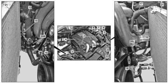
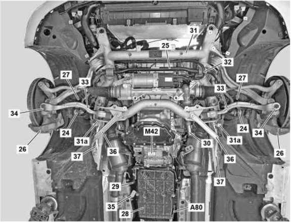
6 II. Engine and Transmission Removal Parts Call Out 1. Null 2. Engine covers 3. Engine air intake duct 4. Air filter housing 5. Foam fuel injector covers 6. Refrigerant line 7. Bulkhead 8. Fuel line 9. Fuel distributor 10. Heater shutoff valve 11. Purge line 12. Coolant hose 13. Coolant hose 14. Vacuum line 15. Coolant hose 16. Coolant hose 17. Coolant hose 18. Oil cooling lines 19. Vent line 20. Cooling air lines 20L. Cooling air line 20R. Cooling air line 21. Radiator 22. Cold air intake 23. Radiator crossmember 24. Torsion bar linkage 25. Stabilizer bar 26. Brake caliper 27. Suspension strut 28. Transmission 29. Wiring harness 30. Steering coupling 31. Front axle carrier 31a. Screw/bolt 32. Electrical line 33. Bracket 34. Cross strut 5

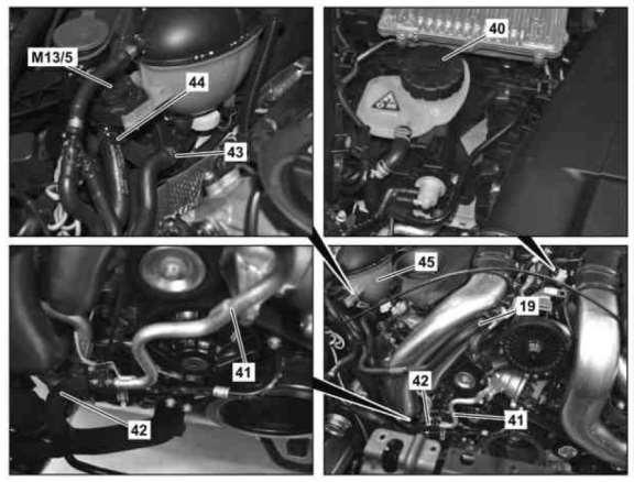
7 35. Bracket 36. Diagonal struts 37. Supporting struts 38. M13/5. Coolant circulation pump 39. Refrigerant line 40. Low-temperature circuit coolant expansion reservoir 41. Coolant line 42. Coolant hose 43. Coolant line 44. Coolant hose 45. Coolant expansion reservoir high temperature cooling system A80. Intelligent servo module for DIRECT SELECT M42. Electric transmission oil pump Y58/1. Purging switchover valve 6
8 7
9 8

10 1. Turn front wheels straight ahead and secure steering wheel 2. Put transmission in neutral and release parking brake 3. Disconnect ground from batter 4. Secure vehicle on a lift IF PROPER MERCEDES PROCEDURE IS NOT FOLLOWED, THE VEHICLE MAY BE PERMANENTLY DAMAGED AND/OR MAY FALL OFF THE LIFT 5. Remove lower engine compartment paneling 6. Drain coolant 7. Remove engine covers 8. Remove front section of the upper engine cover 9. Drain coolant from intercooler system 10. Remove both intake ducts 11. Remove airboxes 12. Discharge AC 9
11 13. Disconnect refrigerant line (6) at upper engine compartment connecting point and close off openings with plugs 14. Remove purge line (11) at purging switchover valve (Y58/1) 15. Disconnect vacuum line (14) on bulkhead (7) connecting point and place to one side 16. Remove coolant hose (12) on heater shutoff valve (10) and bulkhead (7) and remove upwards 17. Disconnect bleed line (19) at connecting point 18. Disconnect coolant hose (42) to the low-temperature circuit coolant expansion reservoir (40) 19. Disconnect coolant line (43) from distributor below the high-temperature cooling system coolant expansion reservoir (45) 20. Remove coolant hose (44) on the coolant circulation pump (M13/5) 21. Remove coolant hose (13) at coolant pump and cooler (21) and place to one side 22. Remove coolant hoses (15, 16) at coolant lines for charge air cooler 23. Remove coolant hose (17) at thermostat housing and cooler (21) and remove 24. Remove cold air intake 25. Fasten cooler (21) to upper radiator crossmember (23) and secure against falling down 26. Disconnect engine wiring harness on the vehicle side 27. Remove front wheels 28. Remove torsion bar linkage (24) from stabilizer bar (25) 29. Remove brake calipers (26) from steering knuckles and fasten with attached lines to suspension strut (27) 30. Remove electrical line to intelligent servo module for DIRECT SELECT (A80) and unclip on transmission (28) 31. Remove shift rod from range selector lever on transmission (28) 32. Disconnect electrical line on electrical transmission oil pump (M42) and unclip on transmission (28) 33. Remove heat shield 34. Disconnect transmission control electrical connection and place wiring harness (29) outside the working area 35. Disconnect exhaust system at center muffler connecting point on rear muffler 36. Remove steering coupling (30) 37. Disconnect refrigerant line (39) at lower connecting point and close off openings with a stop plug 38. Remove electrical line (32) at rack-and-pinion steering, unclip on front axle carrier (31) and set aside 10
12 39. Disconnect lower oil cooling lines (18) of transmission (28) at connecting point and close off openings with stop plug 40. Remove oil lines to engine oil cooler and close off openings with a stop plug 41. Disconnect oil lines at connecting point to engine oil cooler and close off openings with a stop plug 42. Disconnect electrical connections from rpm sensors, right front brake pad contact sensor and front axle damping valve unit electrical connection on left and right and unclip electrical lines at brackets 43. Remove suspension strut (27) from steering knuckle 44. Remove bracket (33) for front level sensor link rod from crow strut (34) 45. Remove bracket (35) for the lower engine compartment paneling 46. Relieve fuel pressure over diagnostic socket Please be aware that the fuel system may retain fuel pressure that can be extremely dangerous if removed suddenly. Proceed with caution. Please be aware of dripping fuel that may get on parts that can be affected. Please cover fuel line with a shop rag in this case. 47. Remove fuel line (8) and fuel distributor (9) and close off opening using suitable stop plugs 48. Remove strut between RH and LH side of underfloor 49. Remove diagonal strut (36) of front axle carrier (31) 50. Remover supporting strut (37) of front axle carrier (31) 51. Remove coolant lines (20L, 20R) for engine mount 52. Support front axle carrier (31) with lifting platform and aggregate mount and secure whole engine transmission unit against slipping and falling down with a tensioning strap 53. Remove rear engine crossmember with rear engine mount 54. Remove drive shaft from transmission output flange/transfer case 55. Remove screw/bolts (31a) on front axle carrier (31) from longitudinal members 56. Lower engine transmission unit with front axle carrier (31) 11

13 III. Downpipes Parts callout Turbochargers 1. Turbocharger with exhaust manifold 1a. Nuts 1b. Nuts 2. Exhaust Pipe 3. Locking plate 4. Null 5. Clamp 6. Clamp 7. Shield 8. Shield 9. Bracket 12
 on shield (7) 3.")
14 Parts call out Charge Air Ducts 1. Nuts 1l. Nuts 1r. Nuts 2. Lower charge air ducts 2l. Lower charge air duct on the left 2r. Lower charge air duct on the right 3. Null 4. Air cleaner housing 5. Charge air cooler 1. Drain engine oil 2. Detach clamp (6) on shield (7) 3. Remove refrigerant line on AC compressor 13
15 4. Remove shield (7) on engine support 5. Remove shield (8) on cylinder head 6. Remove charge air ducts by: a. Loosen clamp between upper charge air duct (1l, 1r) and air filter housing (4) b. Loosen clamp between upper charge air duct (1l, 1r) and turbocharger c. Remove screw/bolt for upper charge air duct (1l, 1r) on cylinder head cover d. Remove upper charge air duct (1l, 1r) e. Remove air filter housing (4) f. Detach engine oil cooling oil lines from oil filter hosing and bracket on engine and lay to the side outside the working area g. Loosen clamp between lower charge air duct (2l, 2r) and charge air cooler (6) h. Loosen clamp between lower charger air duct (2l, 2r) and turbocharger i. Remove screw/bolts for right lower charge air duct (2r) from cylinder head j. Remove screw/bolts for lower charge air duct on the left (2l) from cylinder head and oil filter housing k. Remove lower charge air duct (2l, 2r) l. Check boot and rubber seal for cracks or damage and replace if necessary m. Check clamps for damage and replace as necessary 7. Remove bracket (9) between exhaust pipe (2) and cylinder head 8. Remove exhaust pipe (2) 9. Remove lock washer (3) on turbocharger with exhaust manifold (1) 10. Unscrew nuts (1a, 1b) on turbocharger with exhaust manifold (1) 11. For 4matic vehicles only Remove engine mount brackets from engine block and install the Weistec Billet Engine Mount Brackets and Weistec Supplied Engine Mounts using the supplied studs, bolts, and nuts. DO NOT REUSE THE BLUE RUBBER ENGINE MOUNT COVERS FROM THE OEM ENGINE MOUNTS 12. Install Weistec True downpipes in reverse order. Be sure to use the hardware provided with the Weistec True Downpipes to bolt them onto the turbochargers. Torque to 18ft-lbs 13. Install AC Line into AC compressor before installing the engine and transmission back into the vehicle 14
16 IV. Torque specifications 15
17 16
18 Thank you from Weistec Engineering! Always enjoy the added horsepower and torque of the Weistec M157 True Downpipes responsibly. Use best judgment when driving, and remember to have fun! NOTES: 17
Weistec M157 WMI System
 Weistec M157 WMI System Installation Guide 2012-2013 E63 2014+ E63 4matic(S) 2011-2013 CLS63 2014+ CLS63 4matic(S) 2015+ S63 AMG (Without ABC Suspension) This product is legal in California for racing
Weistec M113K Supercharger System Installation Guide
 Weistec M113K Supercharger System Installation Guide WARNING! DO NOT HAVE YOUR ECU REPROGRAMMED ANYWHERE BUT AT WEISTEC FOR THIS SUPERCHARGER. THE AMG 55 USES AN ELECTRONIC THROTTLE CONTROL (ETC), WHICH
Weistec M177 WMI System
 Weistec M177 WMI System Installation Guide 2015+ C63(S) Sedan 2016+ C63(S) Coupe This product is legal in California for racing vehicles only and should never be used upon a highway. This product is legal
CLS63 Weistec M156 Supercharger System Installation Guide Stage 1 / Stage 2
 CLS63 Weistec M156 Supercharger System Installation Guide Stage 1 / Stage 2 WARNING! DO NOT HAVE YOUR ECU REPROGRAMMED ANYWHERE BUT AT WEISTEC FOR THIS SUPERCHARGER. THE AMG 63 USES AN ELECTRONIC THROTTLE
SL63 Weistec M156 Supercharger System Installation Guide Stage 1 / Stage 2
 SL63 Weistec M156 Supercharger System Installation Guide Stage 1 / Stage 2 WARNING! DO NOT HAVE YOUR ECU REPROGRAMMED ANYWHERE BUT AT WEISTEC FOR THIS SUPERCHARGER. THE AMG 63 USES AN ELECTRONIC THROTTLE
SLS825 Weistec Supercharger System Installation Guide
 SLS825 Weistec Supercharger System Installation Guide 2010-Present SLS AMG (Gullwing and Roadster) 2014 SLS Black Series WARNING! DO NOT HAVE YOUR ECU REPROGRAMMED ANYWHERE BUT AT WEISTEC FOR THIS SUPERCHARGER.
1991 Volkswagen Vanagon Syncro
 corner of radiator. See Fig. 1. Fig. 1: Bleeding Cooling System 2. Open bleeder valve in engine compartment (turn counterclockwise). See Fig. 1. Fill expansion tank until full. Start and run engine at
C63 Weistec M156 Supercharger System Installation Guide Stage 3
 C63 Weistec M156 Supercharger System Installation Guide Stage 3 WARNING! DO NOT HAVE YOUR ECU REPROGRAMMED ANYWHERE BUT AT WEISTEC FOR THIS SUPERCHARGER. THE AMG 63 USES AN ELECTRONIC THROTTLE CONTROL
CLK63 (Black Series) Weistec M156 Supercharger System Installation Guide Stage 3
 Weistec M156 Supercharger System Installation Guide Stage 3") CLK63 (Black Series) Weistec M156 Supercharger System Installation Guide Stage 3 WARNING! DO NOT HAVE YOUR ECU REPROGRAMMED ANYWHERE BUT AT WEISTEC FOR THIS SUPERCHARGER. THE AMG 63 USES AN ELECTRONIC
CLK63 (Black Series) Weistec M156 Supercharger System Installation Guide Stage 3 WARNING! DO NOT HAVE YOUR ECU REPROGRAMMED ANYWHERE BUT AT WEISTEC FOR THIS SUPERCHARGER. THE AMG 63 USES AN ELECTRONIC
2/18/2017 Cylinder Head Assembly Service and Repair, Removal and Replacement: Cylinder Head
 Cylinder Head http://repair.alldata.com/alldata/article/display.action?componentid=65&itypeid=401&nonstandardid=2762152&vehicleid=47645&miles=&printfriendl 1/17 RH Splash Shield Accessory Drive Belt, Thermostat
Audi > B4 > Liter V6 2V Engine Mechanical, Engine Code(s): AAH, AFC 10 Engine Assembly
: AAH, AFC 10 Engine Assembly") Audi > B4 > 1993 1995 2.8 Liter V6 2V Engine Mechanical, Engine Code(s): AAH, AFC 10 Engine Assembly Removing The engine is removed from above, after being separated from the transmission. Note: All tie
Audi > B4 > 1993 1995 2.8 Liter V6 2V Engine Mechanical, Engine Code(s): AAH, AFC 10 Engine Assembly Removing The engine is removed from above, after being separated from the transmission. Note: All tie
1997 Volvo 850 GLT. Fig. 2: Removing Drive Shaft, Engine Mount Bolt & Torque Arm (5-Cylinder) Courtesy of VOLVO CARS OF NORTH AMERICA.
 Courtesy of VOLVO CARS OF NORTH AMERICA.") Fig. 2: Removing Drive Shaft, Engine Mount Bolt & Torque Arm (5-Cylinder) 4. Remove front exhaust pipe nuts and springs. Remove front exhaust pipe bolts. Disconnect speedometer. Remove engine mounting
Fig. 2: Removing Drive Shaft, Engine Mount Bolt & Torque Arm (5-Cylinder) 4. Remove front exhaust pipe nuts and springs. Remove front exhaust pipe bolts. Disconnect speedometer. Remove engine mounting
ENGINE ASSEMBLY. COMPONENTS (Part 1)
") 1 of 32 ENGINE ASSEMBLY COMPONENTS (Part 1) 2 of 32 COMPONENTS (Part 2) 3 of 32 COMPONENTS (Part 3) 4 of 32 COMPONENTS (Part 4) 5 of 32 COMPONENTS (Part 5) 6 of 32 COMPONENTS (Part 6) 7 of 32 COMPONENTS
1 of 32 ENGINE ASSEMBLY COMPONENTS (Part 1) 2 of 32 COMPONENTS (Part 2) 3 of 32 COMPONENTS (Part 3) 4 of 32 COMPONENTS (Part 4) 5 of 32 COMPONENTS (Part 5) 6 of 32 COMPONENTS (Part 6) 7 of 32 COMPONENTS
2017+ L5P Duramax 3 ½ Down Pipe & EGR Fix Kit
 2017+ L5P Duramax 3 ½ Down Pipe & EGR Fix Kit Covers installation of PN s: WCF100630, WCF100829 Note: This Kit is for off road competition use only! Off Road Competition Use Tuning & Exhaust System is
 Page 1 of 10 43: Transmission, automatic, B5254T2, AW50/51 AWD V70 XC (01-) / XC70 (-07), 2004, B5254T2, AW50/51 AWD, L.H.D, YV1SZ59H241147306, 147306 15/10/2011 PRINT 43: Transmission, automatic, B5254T2,
2015+ SUBARU STI FRONT-MOUNT INTERCOOLER PARTS LIST AND INSTALLATION GUIDE INSTALL DIFFICULTY DISCLAIMER CAUTION INSTALL PROCEDURE TOOLS NEEDED
 PARTS LIST AND PARTS INCLUDED 1PC ALUMINUM INTAKE PIPE 1PC BAR-AND-PLATE INTERCOOLER 1PC STEEL CRASH BAR W/ MOUNTING HARDWARE 2PC HOT-SIDE INTERCOOLER PIPES 2PC COLD-SIDE INTERCOOLER PIPES 1PC BPV FLANGE
OIL COOLER KIT CHEVY CAMARO 2.0T PARTS LIST AND INSTALLATION GUIDE INSTALL DIFFICULTY DISCLAIMER CAUTION TOOLS NEEDED NOTE INSTALL PROCEDURE
 PARTS LIST AND PARTS INCLUDED 3PC APPLICATION-SPECIFIC MOUNTING BRACKETS 1PC HORN RELOCATION MOUNTING BRACKET 1PC 25-ROW OIL COOLER (SLEEK SILVER OR STEALTH BLACK) 1PC 4'4" STAINLESS STEEL BRAIDED HOSE
CERTAIN 2018 MODEL YEAR EXPEDITION AND NAVIGATOR VEHICLES EQUIPPED WITH R-1234YF REFRIGERANT - SPECIAL R-1234YF REFRIGERANT SERVICE INFORMATION
 PAGE 1 OF 33 CERTAIN 2018 MODEL YEAR EXPEDITION AND NAVIGATOR VEHICLES EQUIPPED WITH R-1234YF REFRIGERANT - SPECIAL R-1234YF REFRIGERANT SERVICE INFORMATION OVERVIEW This program provides special service
WARNING: ALWAYS relieve fuel pressure before disconnecting any fuel related component. DO NOT allow fuel to contact engine or electrical components.
 4.0L V8 - VINS [K,U] Selected Block 1990 Lexus LS 400 For Lextreme Powertrain 2020 S. Hacienda Blvd. # D Hacienda Heights California 91745 Copyright 1998 Mitchell Repair Information Company, LLC Friday,
303-01C Engine 3.5L 2010 Fusion, Milan, MKZ, Fusion Hybrid, Milan Hybrid. REMOVAL Procedure revision date: 10/19/2012. Engine
 2010 MKZ Report a problem with this article 303-01C Engine 3.5L 2010 Fusion, Milan, MKZ, Fusion Hybrid, Milan Hybrid REMOVAL Procedure revision date: 10/19/2012 Engine Special Tool(s) 2,200# Floor Crane,
W205 C63 Suspension Adjustable Suspension Installation Guide
 W205 C63 Suspension Adjustable Suspension Installation Guide 2015+ C63 AMG Sedan 2015+ C63S AMG Sedan Thank you for your purchase of the Weistec W205 C63 Adjustable Suspension. Please follow all directions,
Weistec M156/M159 ENGINE
 Weistec M156/M159 ENGINE Oil / Air Separator System Installation Guide 2007-2011 S63 AMG 2007-2011 ML63 AMG 2007 R63 AMG 2007-2008 CLK63 AMG 2008 CLK63 Black Series 2007-2011 CLS63 AMG 2008-Present C63
INSTALLATION INSTRUCTIONS 88518
 INSTALLATION INSTRUCTIONS 88518 For Rancho Suspension Systems RS6518: 2009 FORD F-150 4WD READ ALL INSTRUCTIONS THOROUGHLY FROM START TO FINISH BEFORE BEGINNING INSTALLATION Rev A IMPORTANT NOTES! WARNING:
2002 Explorer Sport/Sport Trac Workshop Manual
 Page 1 of 17 SECTION 303-01: Engine 4.0L Single Overhead Camshaft (SOHC) IN-VEHICLE REPAIR Procedure revision date: 07/13/2005 Cylinder Head Special Tool(s) Spark Plug Wire Remover 303-106 (T74P-6666-A)
Dodge/Chrysler Cold Air Kit
 Dodge/Chrysler Cold Air Kit INSTALLATION MANUAL: 2005 2009 5.7L & 6.1L Dodge Charger, Challenger, Magnum, and Chrysler 300C Intake P/N: 004Z A02 C000873 A Techco 3125 E. Coronado St, Anaheim, CA 92806
Weistec CLK Black Series SUSPENSION
 Weistec CLK Black Series SUSPENSION Rear Suspension Bushing Upgrade Installation Guide 1 Thank you for your purchase of the Weistec CLK Black Series Rear Suspension Bushing Upgrade for the 2008 Mercedes
This information covers the proper procedure for replacing the Volvo D16F engine in a VT or VNL chassis.
 Volvo Trucks North America Greensboro, NC USA Engine, Replacement DService Bulletin Trucks Date Group No. Page 10.2007 210 139 1(47) Engine, Replacement Volvo D16F VNL, VT W2005773 This information covers
Procharger Stage II Intercooled Supercharger System (11-14 GT)
") Procharger Stage II Intercooled Supercharger System (11-14 GT) Installation Time: Approximately one day. Installed on 2012 Mustang GT 5.0/Manual Required Tools 3/8 Socket Set (Standard and Metric) 1/2
Procharger Stage II Intercooled Supercharger System (11-14 GT) Installation Time: Approximately one day. Installed on 2012 Mustang GT 5.0/Manual Required Tools 3/8 Socket Set (Standard and Metric) 1/2
ENG-16, Turbocharger Replacement (Including Tips on K27 Turbocharger Installation)
") ENG-16, Turbocharger Replacement (Including Tips on K27 Turbocharger Installation) Introduction Replacing the turbocharger on a 951 is not extremely difficult. However, it is very tedious because there
ENG-16, Turbocharger Replacement (Including Tips on K27 Turbocharger Installation) Introduction Replacing the turbocharger on a 951 is not extremely difficult. However, it is very tedious because there
IAG Street Series Air / Oil Separator (AOS) For WRX & WRX STI
 For WRX & WRX STI") IAG Street Series Air / Oil Separator (AOS) For 2006-07 WRX & 2004-07 WRX STI Part# IAG-ENG-7100 Tools Required: Ratchet, torque wrench, extensions, needle nose pliers, hose cutter, snips/scissors, flat
IAG Street Series Air / Oil Separator (AOS) For 2006-07 WRX & 2004-07 WRX STI Part# IAG-ENG-7100 Tools Required: Ratchet, torque wrench, extensions, needle nose pliers, hose cutter, snips/scissors, flat
INSTALLATION INSTRUCTIONS AIR/OIL SEPARATOR KIT
 INSTALLATION INSTRUCTIONS AIR/OIL SEPARATOR KIT 2015+ SUBARU WRX (LHD ONLY) Document: 19-0136 Support: info@radiumauto.com This document covers the installation of the Radium brake master cylinder brace
TSI : Crankcase Oil Separator Housing Replacement. Study Guide TMT Course Code: 8443
 TSI 13-12-04: Crankcase Oil Separator Housing Replacement Study Guide TMT121379 Course Code: 8443 1 TSI-13-12-04: Crankcase Oil Separator Housing Replacement Study Guide 2013 Navistar, Inc. 2701 Navistar
SECTION D Fuel Charging and Controls Turbocharger
 303-04D-i Fuel Charging and Controls Turbocharger 303-04D-i SECTION 303-04D Fuel Charging and Controls Turbocharger CONTENTS PAGE Turbocharger Body On... 303-04D-2 303-04D-2 Fuel Charging and Controls
2002 F-150 Workshop Manual
 Page 1 of 8 SECTION 307-01B: Automatic Transmission 4R70W 2002 F-150 Workshop Manual REMOVAL Procedure revision date: 04/02/2003 Transmission Special Tool(s) Retainer, Torque Converter 307-346 (T97T-7902-A)
2016+ NISSAN TITAN XD
 PARTS LIST AND PARTS INCLUDED 1PC MISHIMOTO INTERCOOLER 2PC SILICONE BOOTS WITH DURACORE TECHNOLOGY 4PC CONSTANT-TENSION T-BOLT CLAMPS 2PC ALUMINUM SPACERS MOUNTING HARDWARE CAUTION Never work on the cooling
BBK Intake Manifold Kit ( L) - Installation Instructions
 - Installation Instructions") BBK Intake Manifold Kit (86-93 5.0L) - Installation Instructions The below installation instructions work for the following products: BBK Intake Manifold Kit (86-93 5.0L) Please read through the instructions
BBK Intake Manifold Kit (86-93 5.0L) - Installation Instructions The below installation instructions work for the following products: BBK Intake Manifold Kit (86-93 5.0L) Please read through the instructions
James Barone Racing Focus ST Transmission Mount Installation Instructions
 Page1 James Barone Racing 2013+ Focus ST Transmission Mount Installation Instructions What you will need: Jack and jack stands. (Jack stands are preferred) o Ramps will work but, the job will be much more
Huron Speed Products Twin Turbo Install Gen 2 CTS-V (09-15)
") Huron Speed Products Twin Turbo Install Gen 2 CTS-V (09-15) The following install guide is simply that, a guide to help you with installation. It is by no means the exact method to perform installation,
Huron Speed Products Twin Turbo Install Gen 2 CTS-V (09-15) The following install guide is simply that, a guide to help you with installation. It is by no means the exact method to perform installation,
INSTALLATION INSTRUCTION 88088
 INSTALLATION INSTRUCTION 88088 For Rancho Suspension Systems RS6588 & RS6589: FORD F-150 READ ALL INSTRUCTIONS THOROUGHLY FROM START TO FINISH BEFORE BEGINNING INSTALLATION Rev B IMPORTANT NOTES! WARNING:
7B1210 COBB BMW N54 Charge Pipe
 7B1210 COBB BMW N54 Charge Pipe Installation Instructions Congratulations on your purchase of the COBB BMW N54 Charge Pipe for your BMW. The following instructions will assist you through your installation
IN-VEHICLE REPAIR. Cylinder Head. Special Tool(s) Timing Tool, Crankshaft TDC (T97T-6303-A) or. Special Tool(s) equivalent
 Timing Tool, Crankshaft TDC (T97T-6303-A) or. Special Tool(s) equivalent") 303-01A-1 IN-VEHICLE REPAIR Cylinder Head Special Tool(s) Torque Wrench Extension 303-575 (T97T-6256-F) or equivalent Special Tool(s) 303-01A-1 Timing Tool, Crankshaft TDC 303-573 (T97T-6303-A) or equivalent
303-01A-1 IN-VEHICLE REPAIR Cylinder Head Special Tool(s) Torque Wrench Extension 303-575 (T97T-6256-F) or equivalent Special Tool(s) 303-01A-1 Timing Tool, Crankshaft TDC 303-573 (T97T-6303-A) or equivalent
Installation Instructions
 Installation Instructions Transverse K04 Tools Required Jack and jack stands Drain pan for coolant and oil 3" and 6" extensions Channel locks 7mm, 8mm, 10mm, 11mm, 12mm, 13mm, and 16mm sockets Oxygen sensor
M177 in model W205. Remove/install Downpipes
 Remove/install Downpipes M177 in model W205 1 Heat shield 2 Screw/bolts 3 Screw/bolts 6 Electrical line 7 Electrical line 8 Electrical line 9 Electrical line 10 Heat shield 17 Screw/bolts 18 Bracket 31
4 December 2017 PN# , , Dodge 6.7L Rumble B SXE (I-00400) 1. BD Rumble B SXE. D o d g e 6. 7 L H P C R Installation Instructions
 1. BD Rumble B SXE. D o d g e 6. 7 L H P C R Installation Instructions") 4 December 2017 PN#1045705, 1045706, 1045708 Dodge 6.7L Rumble B SXE (I-00400) 1 DOWNLOAD ENHANCED INSTALL MANUALS AT dieselperformance.com BD Rumble B SXE D o d g e 6. 7 L H P C R Installation Instructions
4 December 2017 PN#1045705, 1045706, 1045708 Dodge 6.7L Rumble B SXE (I-00400) 1 DOWNLOAD ENHANCED INSTALL MANUALS AT dieselperformance.com BD Rumble B SXE D o d g e 6. 7 L H P C R Installation Instructions
Huron Speed Products Twin Turbo Install Gen 2 CTS-V (09-15)
") Huron Speed Products Twin Turbo Install Gen 2 CTS-V (09-15) 1 2 Remove two bolts in trunk cover with 8mm socket. Pull up on cover to remove. Unscrew net tie down on side cover where battery is located
Huron Speed Products Twin Turbo Install Gen 2 CTS-V (09-15) 1 2 Remove two bolts in trunk cover with 8mm socket. Pull up on cover to remove. Unscrew net tie down on side cover where battery is located
APR, LLC
 + 1. 3 3 4. 5 0 2. 5 1 8 1 4 8 0 0 U S H W Y 2 8 0 W e s t, O p e l i k a, A l a b a m a 3 6 8 0 1 4 8 0 0 U S H W Y 2 8 0 W e s t, O p e l i k a, A l a b a m a 3 6 8 0 1 + 1. 3 3 4. 5 0 2. 5 1 8 1 NOTES:
INSTALLATION INSTRUCTIONS DUAL OIL CATCH CAN KIT
 INSTALLATION INSTRUCTIONS DUAL OIL CATCH CAN KIT SUBARU WRX FA20F ENGINE Document: 19-0135 Support: info@radiumauto.com This dual catch can kit installs in the right-hand side of the engine bay and intercepts
1 of 12 10/5/2015 8:11 AM
 1 of 12 10/5/2015 8:11 AM REMOVAL 1. Perform the fuel pressure release procedure See: Fuel Pressure Release > Procedures > Fuel System Pressure Release Procedure. 2. Recover the refrigerant from the refrigerant
1. With the vehicle in NEUTRAL, position it on a hoist. For additional information, refer to Section
 SECTION 303-01C: Engine 5.4L (4V) 2009 Mustang Workshop Manual REMOVAL Procedure revision date: 07/25/2008 Engine Special Tool(s) Heavy Duty Floor Crane 014-00071 or equivalent Lifting Bracket, Engine
Disconnect the APP sensor harness connector. See Fig. 4. Remove the accelerator pedal mounting nuts. Remove the APP assembly.
 ENGINE CONTROLS - REMOVAL, OVERHAUL & INSTALLATION - 6.6L DIESEL... Page 1 of 41 FUEL SYSTEMS ACCELERATOR PEDAL POSITION SENSOR Removal & Installation Disconnect the APP sensor harness connector. See Fig.
1999 E-Series Workshop Manual
 http://www.fordservicecontent.com/pubs/content/~wsxm/~mus~len/21/sxm31c16.h... Page 1 of 3 SECTION 303-01C: Engine 6.8L 1999 E-Series Workshop Manual IN-VEHICLE REPAIR Procedure revision date: 06/30/1998
Disconnect negative battery cable and remove coolant bottle cap.
 1 of 16 3/25/2012 10:18 AM ools Required SA9105E 3-Bar Engine Support Fixture SA9412G Constant Force Clamp Pliers SA9127E Gage Bar Set Powertrain Assembly Removal Caution: Do not allow smoking or the use
L Intake Manifold Part #
 86-93 5.0L Intake Manifold Part #5001-5002 I N S T A L L A T I O N I N S T R U C T I O N S Supplied Materials Bottom cover, Upper manifold, Lower manifold, Plenum cover plate, 1501 Throttle body (comes
2015 Corvette Supercharger System Instructions
 2015 Corvette Supercharger System Instructions These instructions are meant to serve as a guide to the installation of the ECS 2015 Corvette Supercharging system. Please be sure to use all safety equipment
Engine, removing and installing
 Стр 1 из 16 10-1 Engine, removing and installing Special tools, testers and auxiliary items required Torque wrench VAG 1331 Torque wrench VAG 1332 Engine/transmission jack VAG 1383 A Spring type clip pliers
Intake Manifold Removal
 PLEASE READ ALL OF THE FOLLOWING INSTRUCTIONS CAREFULLY PRIOR TO INSTALLATION. AT ANY TIME YOU DO NOT UNDERSTAND THE INSTRUCTIONS Parts included: -GT350 Intake manifold M-944-M5 -GT350 Air bucket w/filter.
ADJUSTMENTS Mazda MX-3. Fig. 1: Identifying Engine Code & Number Courtesy of MAZDA MOTORS CORP. VALVE CLEARANCE ADJUSTMENT
 Fig. 1: Identifying Engine Code & Number Courtesy of MAZDA MOTORS CORP. ADJUSTMENTS VALVE CLEARANCE ADJUSTMENT 1. No valve clearance adjustment is required, as hydraulic valve lash adjusters are used.
Engine Front Cover. Special Tool(s) Lifting Bracket, Engine (2 required) 303-D087 (D93P-6001-A1) or equivalent. Support Bar, Engine 303-F070
 Lifting Bracket, Engine (2 required) 303-D087 (D93P-6001-A1) or equivalent. Support Bar, Engine 303-F070") SECTION 303-01C: Engine 5.4L (4V) 2009 Mustang Workshop Manual IN-VEHICLE REPAIR Procedure revision date: 07/25/2008 Engine Front Cover Special Tool(s) Lifting Bracket, Engine (2 required) 303-D087 (D93P-6001-A1)
SECTION 303-01C: Engine 5.4L (4V) 2009 Mustang Workshop Manual IN-VEHICLE REPAIR Procedure revision date: 07/25/2008 Engine Front Cover Special Tool(s) Lifting Bracket, Engine (2 required) 303-D087 (D93P-6001-A1)
Repair Instructions BMW ALPINA B5 BMW ALPINA B6
 Dwg.-No. Page of 0 BMW ALPINA B5 BMW ALPINA B6 Expert automotive knowledge is required. These are based on the BMW 545i/550i/650i TIS. If Nm torque settings are not shown, please see the BMW 545i/550i/650i
INTAKE MANIFOLD INSPECTION/REPLACEMENT
 ATTACHMENT III Owner Notification Program 99M01 INTAKE MANIFOLD INSPECTION/REPLACEMENT AFFECTED VEHICLES: 1997 AND 1998 CROWN VICTORIA POLICE INTERCEPTOR VEHICLES WITH 4.6L SOHC ENGINES BUILT AT THE ST.
SALEEN SPEEDLAB BOOST AND WATER TEMPERATURE GAUGE POD KIT
 = SALEEN SPEEDLAB BOOST AND WATER TEMPERATURE GAUGE POD KIT INSTALLATION MANUAL: 2005-09 Mustang 4.6L 3V P/N: 10-8002-C12000B KIT P/N: 10-2903-B11511* Saleen Performance, Inc. 1225 East Maple Rd. Troy,
IAG Competition Series Air / Oil Separator (AOS) For 2017 STI
 For 2017 STI") P IAG Competition Series Air / Oil Separator (AOS) For 2017 STI Part# IAG-ENG-7251 Tools Required: Ratchet, torque wrench, extensions, needle nose pliers, hose cutter, snips/scissors, flat head screw driver,
P IAG Competition Series Air / Oil Separator (AOS) For 2017 STI Part# IAG-ENG-7251 Tools Required: Ratchet, torque wrench, extensions, needle nose pliers, hose cutter, snips/scissors, flat head screw driver,
IE MK5 & MK6 Downpipe Install Guide IEEXCC5
 IE MK5 & MK6 Downpipe Install Guide IEEXCC5 Thank you for purchasing another high quality Integrated Engineering product! This instruction guide is used for installation of IE s 3 Downpipe System for VW
PRE-INSTALLATION Ford F150 4WD 4" Suspension Lift Kit
 2009-2013 Ford F150 4WD 4" Suspension Lift Kit PRE-INSTALLATION 25007 2 - Knuckle (Driv/Pass) 2 - Crossmember (Front/Rear) 2 - Differential Bracket (Driv/Pass) 1 - Diff. Brace Bracket (Pass) 2 - Front
 Page 1 of 11 43: Transmission, automatic, B5244T3, AW55-50/51SN V70 (00-08), 2003, B5244T3, AW55-50/51SN, L.H.D, YV1SW58D132320765, 320765 29/3/2014 PRINT 43: Transmission, automatic, B5244T3, AW55-50/51SN
ALL AMERICAN BILLET. Front Drive System - Small Block Ford Installation Instructions
 ALL AMERICAN BILLET Front Drive System - Small Block Ford Installation Instructions Small Block Ford with AC & PS All American Billet Store (800) 764-0926 www.allamericanbilletstore.com Items needed for
Engine and A4LDE Automatic Transmission Remove and Install ( ) Remove
 Remove") Engine and A4LDE Automatic Transmission Remove and Install ( 3 0) Special Tools 068A -068A Engine lifting bracket -540 Bolt tightening angle gauge Workshop Equipment Transmission jack Workshop crane Assembly
Engine and A4LDE Automatic Transmission Remove and Install ( 3 0) Special Tools 068A -068A Engine lifting bracket -540 Bolt tightening angle gauge Workshop Equipment Transmission jack Workshop crane Assembly
FULL LENGTH HEADERS/ CATTED HEAD PIPES
 INSTALLATION INSTRUCTIONS INS232 2016-2018 CAMARO 6.2L V8 FULL LENGTH HEADERS/ CATTED HEAD PIPES Part #4044 and 40440 Special Tools required: 10mm, 12mm, 13mm, 15mm Socket and Wrenches, Pliers, Saw, Welder
BD TrackMaster S D o d g e H P C R Installation Instructions
 7 July 2016 PN#1045701, 1045702, 1045704 Dodge 6.7L TMS400 (I-00361) 1 BD TrackMaster S400 2008-2012 D o d g e H P C R Installation Instructions 1045701 2008-2009 Dodge 6.7L TMS400 1045702 2010-2012 Dodge
EXPANSION TANK PARTS LIST AND INSTALLATION GUIDE
 PARTS LIST AND INSTALLATION GUIDE PARTS LIST 2 PC APPLICATION-SPECIFIC MOUNTING BRACKETS 2 PC BLACK, ANODIZED 6061 ALUMINUM CATCH CANS 4 PC SILICONE HOSES 4 PC PLASTIC BARBED FITTINGS 4 PC WORM-GEAR CLAMPS
6.4L EGR Delete With Intake Elbow
 6.4L EGR Delete With Intake Elbow J I E C B F D G H A Part# A B C D E F G H I J PACKING LIST: QTY. 2 4 2 4 2 Description Exhaust Block-Off Plate Exhaust Gasket Coolant Line Plugs Brass Barbed Hose Connector
Engine Removal/Installation
 Engine Removal/Installation Make sure jacks and safety stands are placed properly and hoist brackets are attached to correct positions on the engine. (See Section 1). Apply parking brake and block rear
7. Remove the starter motor. Refer to Starter Motor Replacement (2.2L) or Starter Motor Replacement (4.3L).
 or Starter Motor Replacement (4.3L).") 1 of 9 1/5/2013 6:40 PM Removal Procedure 1. Disconnect the battery negative cable. Refer to Battery Replacement. 2. Remove the hood. Refer to Hood Replacement. 3. If the vehicle is equipped with a manual
1 of 9 1/5/2013 6:40 PM Removal Procedure 1. Disconnect the battery negative cable. Refer to Battery Replacement. 2. Remove the hood. Refer to Hood Replacement. 3. If the vehicle is equipped with a manual
SALEEN SPEEDLAB HOOD KIT
 SALEEN SPEEDLAB HOOD KIT INSTALLATION MANUAL: 2005 to '09 Mustang P/N: 10-8002-C11870C Saleen Performance, Inc. 1225 East Maple Rd. Troy, MI 48083 (800)-888-8945 www.saleen.com IF YOU ARE NOT EXPERIENCED
10/13/2016 5:33 PM. Radiator (B205L/R, B235R) To remove
 To remove") 1 of 15 Radiator (B205L/R, B235R) To remove 1. Disconnect the vent hose from the battery. Disconnect the positive and negative battery cables and remove the battery. Note the radio code where applicable.
1 of 15 Radiator (B205L/R, B235R) To remove 1. Disconnect the vent hose from the battery. Disconnect the positive and negative battery cables and remove the battery. Note the radio code where applicable.
1983 BMW 320i. 1.8L 4-CYL 1983 Engines - 1.8L 4-Cylinder Engines - 1.8L 4-Cylinder
 ENGINE IDENTIFICATION 1.8L 4-CYL 1983 Engines - 1.8L 4-Cylinder For engine repair procedures not covered in this article, see ENGINE OVERHAUL PROCEDURES - GENERAL INFORMATION article in the GENERAL INFORMATION
List of parts needed below. Tools needed
 1 BMW 645 Coolant leak repair (Cap with Seal Repair and Expanding Coolant Pipe Installation w Pics) By Michael R. Brown (Estimated time to complete the job is 6-8 hrs) List of parts needed below. BMW PART
INTERCOOLER PIPE KIT CHEVY CAMARO 2.0T PARTS LIST AND INSTALLATION GUIDE PARTS INCLUDED CAUTION INSTALL PROCEDURE TOOLS NEEDED
 PARTS LIST AND PARTS INCLUDED 2PC ALUMINUM PIPES W/ CNC-MACHINED QUICK-DISCONNECTS 1PC ALUMINUM PIPE W/ CNC-MACHINED 2-BOLT FLANGE 2PC QUICK-DISCONNECT SPRING CLIPS 1PC 2.75" 90 SILICONE COUPLER 1PC 2.25"
SCION tc LOWERING SPRINGS Preparation
 Preparation Part Number: PTR11-21100 PTR11-21100-50 Kit Contents Item # Quantity Reqd. Description 1 2 Front Spring 2 2 Rear Spring 3 2 Locking Nut 4 2 Spring Bumper, Front 5 1 Instruction Form Hardware
NISSAN FRONTIER 2 & 4WD AUTOMATIC & MANUAL TRANS. KING & CREW CAB MODELS 3 BODY LIFT KIT INSTALLATION INSTRUCTIONS KIT# 40083
 3651 N Highway 89 Chino Valley, AZ 86323 (928) 636-7080 www.p-a-g.net NISSAN FRONTIER 2 & 4WD AUTOMATIC & MANUAL TRANS. KING & CREW CAB MODELS 3 BODY LIFT KIT INSTALLATION INSTRUCTIONS 2005-2011 KIT# 40083
This information covers procedures for replacing the sealant for the crankshaft cover on the Volvo D16F engine.
 Volvo Trucks North America Greensboro, NC USA DService Bulletin Trucks Date Group No. Page 1.2008 216 50 1(17) Sealant Crankshaft Cover, Replacement D16F Sealant Crankshaft Cover, Replacement W2005773
Tools Required. Metric Wrench Set Screwdriver Set Metric Socket Set Pliers Heavy duty hydraulic Jack and Car Stands Box knife or similar Hacksaw WD40
 Subaru 2004+ Legacy GT & Outback XT For JDM 2.0 twinscroll turbo and USDM 2.5 turbo models Front Mount Intercooler Fitting Instructions PN# LEG-1348-000 You are now the proud owner of a highly tested and
INSTALLATION INSTRUCTION 88581
 INSTALLATION INSTRUCTION 88581 FOR RANCHO SUSPENSION SYSTEM RS6581B: DODGE RAM READ ALL INSTRUCTIONS THOROUGHLY FROM START TO FINISH BEFORE BEGINNING INSTALLATION Rev C IMPORTANT NOTES! WARNING: This suspension
1 of 14 11/19/ :45 AM
 1 of 14 11/19/2016 11:45 AM 6F35 Digital Transmission Range (TR) Sensor Removal All vehicles 1. With the vehicle in NEUTRAL, position it on a hoist. 3.0L engine 2. Remove the Air Cleaner (ACL) outlet pipe.
Lower Intake Manifold Replacement
 Lower Intake Manifold Replacement Removal Procedure 1. Turn OFF all the lamps and the accessories. 2. Ensure the ignition switch is in the OFF position. 3. Disconnect the negative battery cable from the
Wrenches: ⅞, 8mm, 10mm, 13mm, 19mm P. allen, Other: Electrical Tape
 IAG Street Series Air / Oil Separator (AOS) For 2008-14 STI Part# IAG-ENG-7100 Tools Required: Ratchet, torque wrench, extensions, needle nose pliers, hose cutter, snips/scissors, flat head screw driver,
TURBOCHARGER L INSTALLATION GUIDE
 1 TURBOCHARGER INSTALLATION GUIDE TABLE OF CONTENTS Chapter Page 1 Intake and Cooling System Preparation 04 2 Intake Plenum and Manifold 08 3 Turbocharger Lubrication 11 4 Fuel Injectors 13 5 Re-installing
3.4L V6 SUPERCHARGER 7 TH INJECTOR KIT
 Part Number: 00602-17620-260 00602-17620-261 00602-17620-263 00602-17620-264 00602-17620-274 00602-17620-275 00602-17620-276 Section I Installation Preparation Kit Contents Item # Quantity Reqd. Description
Exhaust Gas Recirculation Valve, Replace J S file://c:\program Files\cosids\DATA\TMP\ rtf.html. Remove
 1 Page 1 of 20 Exhaust Gas Recirculation Valve, Replace J982500 Remove 1. Disconnect battery negative lead 2. Disconnect hose (1) from oil filler on air cleaner assembly, then move to one side Release
2013 Kia Optima L4-2.0L Turbo
 1 of 13 5/29/2016 11:34 AM 2013 Kia Optima L4-2.0L Turbo Vehicle» Engine, Cooling and Exhaust» Engine» Service and Repair» Removal and Replacement Removal CAUTION: Use fender covers to avoid damaging painted
Cylinder head, removing and
 Page 1 of 35 15-2 Cylinder head, removing and installing Note: Replace cylinder head bolts. Always replace self-locking nuts, bolts as well as gaskets and O-rings. After installing a replacement cylinder
PRE-INSTALLATION. INSTALLATION INSTRUCTIONS Front Ford F150 4WD 4" Suspension Lift Kit
 2015 Ford F150 4WD 4" Suspension Lift Kit PRE-INSTALLATION 2 - Knuckle (Driv/Pass) 2 - Crossmember (Front/Rear) 2 - Differential Bracket (Driv/Pass) 1 - Diff. Brace Bracket (Pass) 2 - Front Brake Line
SLP Camaro ZL1 STAGE 3 (650 HP)
") SLP - 2012 Camaro ZL1 STAGE 3 (650 HP) PART #26002 PACKING LIST Before installation, use this check list to make sure all necessary parts have been included. ITEM QTY CHECK PART NUMBER DESCRIPTION 1. 1
SLP - 2012 Camaro ZL1 STAGE 3 (650 HP) PART #26002 PACKING LIST Before installation, use this check list to make sure all necessary parts have been included. ITEM QTY CHECK PART NUMBER DESCRIPTION 1. 1
16A. STARTING - CHARGING Starter: Removal - Refitting REFITTING 16A-11 K4M II - REMOVAL OPERATION III - FINAL OPERATION
 STARTING - CHARGING Starter: Removal - Refitting 16A K4M II - REMOVAL OPERATION III - FINAL OPERATION JR5 a Clip: -the gearbox control cable sleeve stops on the gearbox, - the control cables onto the gearbox.
IAG Competition Series Air / Oil Separator (AOS) For WRX
 For WRX") P IAG Competition Series Air / Oil Separator (AOS) For 2015-16 WRX Part# IAG-ENG-7252 Tools Required: Ratchet, torque wrench, extensions, needle nose pliers, hose cutter, snips/scissors, flat head screw
P IAG Competition Series Air / Oil Separator (AOS) For 2015-16 WRX Part# IAG-ENG-7252 Tools Required: Ratchet, torque wrench, extensions, needle nose pliers, hose cutter, snips/scissors, flat head screw
Zoom and Print Options
 Vehicle» Engine, Cooling and Exhaust» Engine» Service and Repair» Removal and Replacement» Engine Replacement Engine Replacement ^ Tools Required - J 38185 Hose Clamp Pliers Removal Procedure 1. Remove
Audi S1 Intake kit. Qty. Description
 Audi S1 Intake kit Description Qty Silicone Intake pipe 1 Vacuum hose 1 Heatshield 1 Bracket 1 Machined inlet 1 Vacuum connector 1 Filter 1 M6x16 cap head bolt 1 Tools Ratchet Extension Torx socket Sockets
IAG Street Series Air / Oil Separator (AOS) For WRX & WRX STI
 For WRX & WRX STI") IAG Street Series Air / Oil Separator (AOS) For 2006-07 WRX & 2004-07 WRX STI Part# IAG-ENG-7150 Tools Required: Ratchet, torque wrench, extensions, needle nose pliers, hose cutter, snips/scissors, flat
IAG Street Series Air / Oil Separator (AOS) For 2006-07 WRX & 2004-07 WRX STI Part# IAG-ENG-7150 Tools Required: Ratchet, torque wrench, extensions, needle nose pliers, hose cutter, snips/scissors, flat
03-04 Mach 1. Hellion Power Systems Mach 1 Kit Instructions
 Hellion Power Systems 03-04 Mach 1 Kit Instructions Part 1 Hellion recommends that the front suspension system be installed either by trained professionals or by 5.Remove rack bolts K-Member Installation
Page 6 of 6 OUTLAW DIESEL EGR COOLER DELETE KIT W/INTAKE ELBOW L FORD POWERSTROKE
 What s in the box 1 Exhaust Block-Off Plate 1 Exhaust Gasket 2 Coolant Line Plugs 1 Brass Barbed Hose Connector 1 Stand-off Spacer 4 M10-1.25 x 40 Hex Head Bolts (Exhaust Manifold) 2 M10-1.25 x 20 Hex