1999 E-Series Workshop Manual
|
|
|
- Florence Tyler
- 6 years ago
- Views:
Transcription
. 2.")
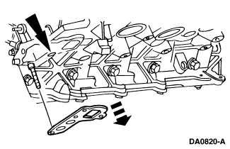
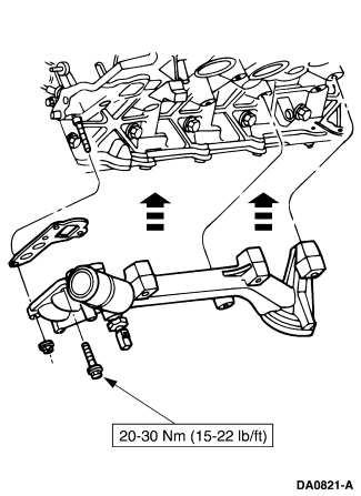
1 Page 1 of 3 SECTION C: Engine 6.8L 1999 E-Series Workshop Manual IN-VEHICLE REPAIR Procedure revision date: 06/30/1998 Oil Cooler Oil Filter Adapter Removal 1. Disconnect the battery ground cable (14301). 2. Raise and support the vehicle. Refer to Section Remove the left engine support insulator. Refer to Engine Support Insulators in this section. 4. Remove the lower radiator hose (8286). Refer to Section Drain the engine oil and remove the oil bypass filter (6714). 6. Loosen the threaded tube and remove the oil cooler (6A642) from the oil filter adapter (6881). 7. Remove one nut and two bolts and remove the oil filter adapter from the cylinder block (6010). 8. Remove the old oil filter adapter gasket (6840) and clean the gasket surface at the cylinder block.
2 Page 2 of 3 Installation 1. Follow the removal procedure in reverse order.

3 Page 3 of 3 2. Fill the engine cooling system. Refer to Section Fill the crankcase with Super Premium SAE 5W-30 Motor Oil XO-5W30-QSP or equivalent meeting Ford specification WSS-M2C153-G.
 Modular Lifting Bar 303-F047 (014-00073) or equivalent 3-Bar Engine")
4 Page 1 of 7 SECTION C: Engine 6.8L 1999 E-Series Workshop Manual IN-VEHICLE REPAIR Procedure revision date: 06/30/1998 Engine Support Insulators Special Tool(s) Modular Lifting Bar 303-F047 ( ) or equivalent 3-Bar Engine Support 303-F070 Lift Bar Adapter, Modular Engine 303-F694 Removal 1. Remove the intake manifold. For additional information, refer to Intake Manifold Variable Resonance Induction System (VRIS) in this section. 2. Remove the fan shroud and the engine cooling fan. For additional information, refer to Section Remove the retainers and the shield.


5 Page 2 of 7 4. Remove the nut retaining the transmission oil filler tube and position the tube aside. 5. Detach the wiring harness retainer. 6. Remove the stud bolts. 7. Remove the two transmission-to-engine bolts. 8. Assemble the special tools.


6 Page 3 of 7 9. Install the special tools. 10. Install the special tool and support the engine. 11. Raise the vehicle. For additional information, refer to Section NOTE: The RH is shown, the LH is similar. Remove the nuts retaining the front engine support insulators (6038) to the engine support brackets.

7 Page 4 of For the RH front engine support insulator, remove the starter motor (11001). For additional information, refer to Section A. 14. Lower the vehicle. 15. Using the 3-Bar Engine Support, raise the engine. 16. Raise the vehicle. 17. NOTE: Engine is not shown for clarity. Remove the bolts and remove the front engine support insulators from the vehicle.
8 Page 5 of 7 Installation 1. To install, reverse the removal procedure.

9 Page 6 of 7
10 Page 7 of 7
11 Page 1 of 18 SECTION C: Engine 6.8L 1999 E-Series Workshop Manual IN-VEHICLE REPAIR Procedure revision date: 06/30/1998 Intake Manifold Variable Resonance Induction System (VRIS) Removal WARNING: Do not smoke or carry lighted tobacco or open flame of any type when working on or near any fuel-related components. Highly flammable mixtures are always present and can be ignited, resulting in possible personal injury. WARNING: Fuel in the fuel system remains under high pressure even when the engine is not running. 1. Disconnect the battery ground cable (14301). For additional information, refer to Section Relieve the fuel pressure. For additional information, refer to Section A. 3. Disconnect the fuel lines. For additional information, refer to Section A. 4. Remove the evaporative emission canister purge valve and mounting bracket. For additional information, refer to Section Drain the coolant system. For additional information, refer to Section Compress and slide the hose clamp and disconnect the water outlet hose. 7. Remove the engine vacuum harness. Disconnect the harness as shown. 1. EGR valve (EGR valve) (9D475) 2. EGR vacuum regulator solenoid 3. vacuum source 4. fuel pressure regulator (9C968)
12 Page 2 of Disconnect the exhaust gas recirculation (EGR) valve to exhaust manifold tube lower fitting.

13 Page 3 of Remove the differential pressure feedback EGR. For additional information, refer to Section Remove the EGR vacuum regulator solenoid. For additional information, refer to Section Remove the EGR valve. For additional information, refer to Section Remove the throttle body. For additional information, refer to Section D. 13. Remove the throttle body spacer and gasket. 14. Disconnect the five RH fuel injector electrical connectors.

14 Page 4 of Disconnect the five LH fuel injector electrical connectors.
15 Page 5 of Disconnect the water temperature indicator sender unit electrical connectors.
. For additional information, refer to Section 303-05. 19. Remove the generator (GEN) (10300).")
16 Page 6 of Disconnect and remove the ten ignition coils (12029). For additional information, refer to Section C. 18. Remove the drive belt (8620). For additional information, refer to Section Remove the generator (GEN) (10300). For additional information, refer to Section A. 20. Disconnect the hose clamps and remove the heater water hose (18472). 21. Remove the water thermostat (8575).
. Discard the intake manifold gaskets. 24. Pull back and remove the heater water return tube.")
17 Page 7 of Remove the two studs retaining the heater water return tube. 23. Remove the bolts, the upper intake manifold and the intake manifold gaskets (9439). Discard the intake manifold gaskets. 24. Pull back and remove the heater water return tube. Inspect the O-rings and replace if required. 25. Separate the upper and lower intake manifolds (9424). Remove the ten bolts. Discard the intake manifold gasket.
18 Page 8 of Clean all mating surfaces. Installation 1. Position the lower intake manifold gasket (9461) and the upper intake manifold on the intake manifold and loosely install the ten bolts.
19 Page 9 of NOTE: Tighten the bolts in two stages. Tighten the bolts in the sequence shown. Stage 1: Tighten to 2 Nm (18 lb/in) Stage 2: Tighten to 8-12 Nm ( lb/in)

20 Page 10 of Position the water return tube as shown. 4. Install the heater water return tube studs.

21 Page 11 of Install the upper intake manifold. Position the upper intake manifold gaskets and the intake manifold, and loosely install the bolts. 6. NOTE: Be sure to tighten the bolts in two stages. Tighten the bolts in the sequence shown. Stage 1: Tighten to 2 Nm (18 lb/in) Stage 2: Tighten to Nm (15-22 lb/ft)

22 Page 12 of Install the thermostat. For additional information, refer to Section Install the heater water hose and position the clamp. 9. Connect the water temperature indicator sending unit electrical connector.
23 Page 13 of Install the generator. For additional information, refer to Section A. 11. Install the drive belt. For additional information, refer to Section Install the ignition coils. For additional information, refer to Section C. 13. Connect the five LH fuel injector electrical connectors.
24 Page 14 of Connect the five RH fuel injector electrical connectors.

25 Page 15 of Install a new throttle body spacer gasket and the throttle body spacer. 16. Install the throttle body. For additional information, refer to Section D. 17. Install the EGR valve. For additional information, refer to Section Install the EGR vacuum regulator solenoid. For additional information, refer to Section Install the differential pressure feedback EGR. For additional information, refer to Section Connect the EGR valve to exhaust manifold tube lower fitting.
26 Page 16 of Connect the engine emission vacuum harness. 1. EGR valve 2. EGR vacuum regulator solenoid 3. vacuum source 4. fuel pressure regulator

27 Page 17 of Connect the fuel lines. For additional information, refer to Section A. 23. Install the evaporative emission canister purge valve and mounting bracket. For additional information, refer to Section Connect the engine water outlet hose and position the hose clamp. 25. Install the air cleaner outlet tube (9B659). For additional information, refer to Section Fill the cooling system. For additional information, refer to Section
28 Page 18 of Install the engine cover. For additional information, refer to Section Connect the battery ground cable. For additional information, refer to Section

29 Page 1 of 3 SECTION : Engine Cooling 1999 E-Series Workshop Manual REMOVAL AND INSTALLATION Procedure revision date: 06/30/1998 Water Pump 4.6L, 5.4L and 6.8L Removal 1. Drain the cooling system. For additional information, refer to Cooling System Draining, Filling and Bleeding in this section. 2. Remove the fan and fan clutch. For additional information, refer to Fan in this section. 3. Remove the accessory drive belt. For additional information, refer to Section Remove the water pump pulley. 1. Remove the bolts. 2. Remove the water pump pulley. 5. Remove the (A) bolts and the (B) water pump from the (C) engine. Installation 1. NOTE: New water pumps are shipped with a new O-ring in place. Only lubricate if the old pump is to be reinstalled.

 water pump on the (B) engine and install the (C) bolts. 3. Position the pulley onto the water pump and install the bolts. 4. Install the accessory drive belt.")
30 Page 2 of 3 Install a new O-ring on the water pump. Coat the new O-ring with Ford Premium Engine Coolant E2FZ AA or B, in Oregon F5FZ CC, in Canada Motorcraft CXC-10 or equivalent meeting Ford specification ESE-M97B44-A. 2. CAUTION: Do not rotate the water pump housing once installed in the engine. Damage to the O-ring can occur, causing the water pump to leak. Position the (A) water pump on the (B) engine and install the (C) bolts. 3. Position the pulley onto the water pump and install the bolts. 4. Install the accessory drive belt. For additional information, refer to Section Install the fan and fan clutch. For additional information, refer to Radiator Cooling Fan Blade/Fan Clutch and Fan Shroud in this section. 6. Refill the cooling system. For additional information, refer to Cooling System Draining, Filling and Bleeding in this section.
31 Page 3 of 3
32 Page 1 of 4 SECTION A: Starting System Gasoline Engines 1999 E-Series Workshop Manual REMOVAL AND INSTALLATION Procedure revision date: 06/30/1998 Starter Motor Removal WARNING: When carrying out maintenance on the starting system, be aware that heavy gauge leads are connected directly to the battery. Make sure protective caps are in place when maintenance is complete. 1. Disconnect the battery ground cable (14301). For additional information, refer to Section Raise and support the vehicle. For additional information, refer to Section Remove the starter motor solenoid terminal cover (11N087). 4. Disconnect the starter motor electrical connections. 1. Remove the nuts (B+ and S). 2. Remove the battery cable. 3. Remove the starter solenoid wire. 5. Remove the nut and the starter motor ground cable.
33 Page 2 of 4 6. Remove the starter motor (11002). 1. NOTE: Most applications use two bolts; however, some use three bolts. Remove the bolts. 2. Remove the starter motor. Installation WARNING: When carrying out maintenance on the starting system, be aware that heavy gauge leads are connected directly to the battery (10653). Make sure the protective caps are in place when the maintenance is complete. 1. Install the starter motor. 1. Position the starter motor. 2. NOTE: Most applications use two bolts; however, some use three bolts. Install the bolts.

34 Page 3 of 4 2. Connect the starter motor ground cable and install the nut. 3. Connect the starter motor electrical connections. 1. Position the battery cable. 2. Position the starter solenoid wire. 3. Install the nuts. 4. Install the starter motor solenoid terminal cover.
35 Page 4 of 4 5. Lower the vehicle. 6. Reconnect the battery ground cable.
36 Page 1 of 5 SECTION : Engine Cooling 1999 E-Series Workshop Manual REMOVAL AND INSTALLATION Procedure revision date: 11/02/2002 Fan Special Tool(s) Holding Wrench, Fan Clutch Pulley (4.2L, 4.6L, 5.4L) (T84T-6312-C) Wrench, Fan Clutch Hub Nut (4.2L, 4.6L, 5.4L) (T84T-6312-D) Holding Wrench, Fan Clutch Pulley (6.8L, 7.3L) (94T-6312-AH) Wrench, Fan Clutch Hub Nut (6.8L, 7.3L) (T83T-6312-B) Removal and Installation All vehicles NOTE: The fan, fan clutch and shroud must be removed and installed together due to insufficient clearance to remove them separately. 1. Drain the cooling system. For additional information, refer to Cooling System Draining, Filling and Bleeding in this section. 2. Remove the air cleaner assembly. For additional information, refer to Section Disconnect the radiator upper hose from the radiator. Position the radiator hose aside. 4. Disconnect the overflow hose from the radiator.


37 Page 2 of 5 5. Disconnect the coolant degas bottle hose from the shroud. Vehicles with 4.2L, 4.6L, 5.4L engine 6. CAUTION: The clutch assembly nut has a right-hand thread and must be rotated counterclockwise to remove it. Using the special tools, loosen the fan clutch. Vehicles with 6.8L, 7.3L engine

38 Page 3 of 5 7. CAUTION: The clutch assembly nut has a right-hand thread and must be rotated counterclockwise to remove it. Using the special tools, loosen the fan clutch. All vehicles 8. Carefully rotate the fan and fan clutch assembly counterclockwise until the assembly is free from the water pump. Place the fan and fan clutch into the shroud opening. 9. If equipped, disconnect the retaining clips from the fan shroud. 10. Raise and support the vehicle. For additional information, refer to Section Disconnect the lower radiator hose retaining clamp from the shroud.


39 Page 4 of If equipped, disconnect the underbody splash shield from the shroud. 13. Lower the vehicle. 14. CAUTION: Use extreme care when removing or installing the fan, fan clutch and shroud. Failure to do so will cause damage to the radiator. Remove the mounting bolts, and the fan, fan clutch and shroud. 15. To install, reverse the removal procedure. Install an appropriately sized worm drive-type clamp in place of the constant tension clamp.
40 Page 5 of 5

41 Page 1 of 4 SECTION : Engine Cooling 1999 E-Series Workshop Manual REMOVAL AND INSTALLATION Procedure revision date: 06/30/1998 Radiator Cooling Fan Blade/Fan Clutch and Fan Shroud Removal 1. Drain the cooling system. For additional information, refer to Cooling System Draining, Filling and Bleeding in this section. 2. Remove the air cleaner assembly. For additional information, refer to Section Remove the plastic rivet retainers and the air deflector. 4. Remove the upper radiator hose from the radiator. 5. Disconnect the overflow hose from the radiator. 6. CAUTION: The large clutch assembly nut has a right hand thread and must be rotated counterclockwise to remove it. Remove the (A) fan and fan clutch from the (B) water pump pulley (8509).
42 Page 2 of 4 7. Remove the (A) bolts and lift the (B) fan shroud (8146), fan and fan clutch from the vehicle. 8. Raise and support the vehicle. For additional information, refer to Section Remove the underbody splash shield, if equipped. 10. Remove the lower radiator hose. 11. Compress the (A) clamps and slide away from the (B) radiator. Twist the (C) transmission oil cooler hoses and remove from the radiator. 12. Lower the vehicle.

 bolts retaining the (B) support brackets to")

43 Page 3 of Remove the (A) bolts retaining the (B) support brackets to the (C) radiator support. Lift the radiator support brackets upwards and away from the (D) radiator. 14. Remove the radiator from the vehicle. Installation 1. To install, reverse the removal procedure.

44 Page 4 of 4 2. Install hose clamps where the shrink clamps were removed.
2000 Econoline Workshop Manual. 3. Install the upper intake manifold. 2. NOTE: Tighten the bolts in two stages.
 2. NOTE: Tighten the bolts in two stages. Tighten the bolts in the sequence shown. Stage 1: Tighten to 2 Nm (18 lb-in). Stage 2: Tighten to 10 Nm (89 lb-in). 3. Install the upper intake manifold. Position
10/20/ Ford E 250 Engine Mechanical > Engine, 4.6L and 5.4L > IN VEHICLE REPAIR > Intake Manifold 5.4L
 2005 Ford E 250 : Engine Mechanical > Engine, 4.6L and 5.4L > IN VEHICLE REPAIR > Intake Manifold 5.4L Intake Manifold 5.4L Listen SECTION 303 01A: Engine 4.6L and 5.4L 2005 E Series Workshop Manual IN
1998 F-150/250 Workshop Manual
 Page 1 of 13 SECTION 303-01B: Engine 4.6L and 5.4L 1998 F-150/250 Workshop Manual IN-VEHICLE REPAIR Procedure revision date: 03/07/2000 Intake Manifold Removal WARNING: Do not smoke or carry lighted tobacco
2002 Crown Victoria/Grand Marquis Workshop Manual
 Page 1 of 9 SECTION 303-04: Fuel Charging and Controls 2002 Crown Victoria/Grand Marquis Workshop Manual REMOVAL AND INSTALLATION Procedure revision date: 06/13/2001 Fuel Injection Supply Manifold Material
 Page 1 of 6 Section 303-01A: Basic Engine 4.2L REMOVAL 1997 F-150/250 Workshop Manual Engine Special Service Tool(s) Engine Lifting Bracket or equivalent 014-00730 Removal 1. Remove the hood. 2. On A/C
2002 Explorer Sport/Sport Trac Workshop Manual
 Page 1 of 17 SECTION 303-01: Engine 4.0L Single Overhead Camshaft (SOHC) IN-VEHICLE REPAIR Procedure revision date: 07/13/2005 Cylinder Head Special Tool(s) Spark Plug Wire Remover 303-106 (T74P-6666-A)
IN-VEHICLE REPAIR. Cylinder Head. Special Tool(s) Timing Tool, Crankshaft TDC (T97T-6303-A) or. Special Tool(s) equivalent
 Timing Tool, Crankshaft TDC (T97T-6303-A) or. Special Tool(s) equivalent") 303-01A-1 IN-VEHICLE REPAIR Cylinder Head Special Tool(s) Torque Wrench Extension 303-575 (T97T-6256-F) or equivalent Special Tool(s) 303-01A-1 Timing Tool, Crankshaft TDC 303-573 (T97T-6303-A) or equivalent
303-01A-1 IN-VEHICLE REPAIR Cylinder Head Special Tool(s) Torque Wrench Extension 303-575 (T97T-6256-F) or equivalent Special Tool(s) 303-01A-1 Timing Tool, Crankshaft TDC 303-573 (T97T-6303-A) or equivalent
1. With the vehicle in NEUTRAL, position it on a hoist. For additional information, refer to Section
 SECTION 303-01C: Engine 5.4L (4V) 2009 Mustang Workshop Manual REMOVAL Procedure revision date: 07/25/2008 Engine Special Tool(s) Heavy Duty Floor Crane 014-00071 or equivalent Lifting Bracket, Engine
DESCRIPTION AND OPERATION
 303-01B-10 Engine 3.0L 303-01B-10 DESCRIPTION AND OPERATION Upper Engine Components G72932 en 303-01B-11 Engine 3.0L 303-01B-11 DESCRIPTION AND OPERATION (Continued) Item Part Number Description 1 9H589
Intake Components 1117
 Item Part Number Description 1 W705654 Bolt 2 N807309 Bolt (2 req'd) 3 9F460 Bracket 4 N807071 Bolt (5 req'd) 5 9A448 Intake manifold (upper) 6 9E498 Vacuum harness 7 9F792 Fuel injection supply manifold
2002 Crown Victoria/Grand Marquis Workshop Manual
 Page 1 of 24 SECTION 303-01: Engine 2002 Crown Victoria/Grand Marquis Workshop Manual INSTALLATION Procedure revision date: 01/02/2003 Cylinder Heads Special Tool(s) Installer, Crankshaft Vibration Damper
2006 Expedition/Navigator Workshop Manual
 7. Remove the RH variable camshaft timing (VCT) oil control solenoid. For additional information, refer to Section 303-14. 8. Remove the RH ignition coils. For additional information, refer to Section
2009 Mustang Workshop Manual. REMOVAL AND INSTALLATION Procedure revision date: 05/23/2008
 Fuel Rail Pressure and Temperature Sensor - 4.0L SOHC Material Item Motorcraft SAE 5W-30 Premium Synthetic Blend Motor Oil XO-5W30-QSP (US); Motorcraft SAE 5W-30 Super Premium Motor Oil CXO-5W30-LSP12
2012 Mustang Workshop Manual. 14. Position the lower radiator hose assembly into the vehicle. Connect the lower radiator hose to the radiator.
 14. Position the lower radiator hose assembly into the vehicle. Connect the lower radiator hose to the radiator. 15. Connect the coolant hose to the oil cooler. 16. Rotate the SC drive belt tensioner clockwise
Engine Front Cover. Special Tool(s) Lifting Bracket, Engine (2 required) 303-D087 (D93P-6001-A1) or equivalent. Support Bar, Engine 303-F070
 Lifting Bracket, Engine (2 required) 303-D087 (D93P-6001-A1) or equivalent. Support Bar, Engine 303-F070") SECTION 303-01C: Engine 5.4L (4V) 2009 Mustang Workshop Manual IN-VEHICLE REPAIR Procedure revision date: 07/25/2008 Engine Front Cover Special Tool(s) Lifting Bracket, Engine (2 required) 303-D087 (D93P-6001-A1)
SECTION 303-01C: Engine 5.4L (4V) 2009 Mustang Workshop Manual IN-VEHICLE REPAIR Procedure revision date: 07/25/2008 Engine Front Cover Special Tool(s) Lifting Bracket, Engine (2 required) 303-D087 (D93P-6001-A1)
 Page 1 of 6 Section 03-01C: Engine, 7.5L MFI 1996 Bronco/F-Series Workshop Manual IN-VEHICLE SERVICE Procedure revision date: 06/19/2000 Cylinder Heads Removal SPECIAL SERVICE TOOL(S) REQUIRED Description
1999 F-150/250 Workshop Manual
 Page 1 of 8 SECTION 303-01B: Engine 4.6L and 5.4L IN-VEHICLE REPAIR Procedure revision date: 02/03/1999 Intake Manifold Lightning Removal WARNING: Do not smoke or carry lighted tobacco or open flame of
REMOVAL AND INSTALLATION
 303-03-1 Engine Cooling 303-03-1 REMOVAL AND INSTALLATION Radiator, Cooling Fan and Shroud Special Tool(s) Wrench, Fan Clutch Nut 303-240 (T84T-6312-D) Holding Wrench, Fan Pulley 303-239 (T84T-6312-C)
INSTALLATION. Engine. All vehicles. 1. Install the special tool to the threaded hole located at the LH side of the engine block.
 303-01B-1 INSTALLATION Engine 303-01B-1 Special Tool(s) 3-Bar Engine Support Kit 303-F072 Lifting Brackets, Engine 303-050 (T70P-6000) Modular Engine Lift Bracket 303-F047 (014-00073) or equivalent 2.
1996 Aerostar/Ranger/Explorer
 Page 1 of 11 Section 03-01B: Engine, 3.0L V-6 IN-VEHICLE SERVICE 1996 Aerostar and Ranger Vehicles Workshop Manual Water Pump SPECIAL SERVICE TOOL(S) REQUIRED Description Tool Number Fan Clutch Holding
2001 Lincoln LS Workshop Manual
 Page 1 of 10 SECTION 303-01B: Engine 3.9L 2001 Lincoln LS Workshop Manual IN-VEHICLE REPAIR Procedure revision date: 05/16/2000 Intake Manifold Removal 1. Disconnect the battery ground cable. For additional
IN-VEHICLE REPAIR. Engine Front Cover
 303-01B-1 IN-VEHICLE REPAIR Engine Front Cover Material Item Specification 303-01B-1 Special Tool(s) Motorcraft SAE 5W-20 WSS-M2C930-A Premium Synthetic Blend 3-Jaw Puller Motor Oil 303-D121 XO-5W20-QSP
IN-VEHICLE REPAIR. Upper Intake Manifold
 303-01-1 Engine 3.9L and 4.2L 303-01-1 IN-VEHICLE REPAIR Upper Intake Manifold Special Tool(s) Remover, Spark Plug Wire 303-106 (T74P-6666-A) Material Item Silicone Brake Caliper Grease and Dielectric
IN-VEHICLE REPAIR. Oil Pan Lower. Removal. 2. Disconnect the LH and RH battery ground cables. For additional information, refer to Section
 303-01C-1 IN-VEHICLE REPAIR Oil Pan Lower Special Tool(s) 3-Bar Engine Support 303-F070 Lifting Eyes 303-D030 303-01C-1 2. Disconnect the LH and RH battery ground cables. For additional information, refer
2004 F-150 Workshop Manual
 Page 1 of 8 SECTION 303-01B: Engine 5.4L (3V) 2004 F-150 Workshop Manual REMOVAL Procedure revision date: 02/10/2004 Engine Printable View (943 KB) Special Tool(s) Modular Engine Lift Bracket 303-F047
1991 Volkswagen Vanagon Syncro
 corner of radiator. See Fig. 1. Fig. 1: Bleeding Cooling System 2. Open bleeder valve in engine compartment (turn counterclockwise). See Fig. 1. Fill expansion tank until full. Start and run engine at
Engine Front Cover. Special Tool(s) 3-Jaw Puller 303-D121 or equivalent. Installer, Front Cover Oil Seal (T88T-6701-A)
 3-Jaw Puller 303-D121 or equivalent. Installer, Front Cover Oil Seal (T88T-6701-A)") SECTION 303-01B: Engine 4.6L (3V) 2009 Mustang Workshop Manual IN-VEHICLE REPAIR Procedure revision date: 05/23/2008 Engine Front Cover Special Tool(s) 3-Jaw Puller 303-D121 or equivalent Installer, Front
SECTION 303-01B: Engine 4.6L (3V) 2009 Mustang Workshop Manual IN-VEHICLE REPAIR Procedure revision date: 05/23/2008 Engine Front Cover Special Tool(s) 3-Jaw Puller 303-D121 or equivalent Installer, Front
M-9424-M50B 2012 Boss 302 Intake Manifold INSTALLATION INSTRUCTIONS
 !!! PLEASE READ ALL OF THE FOLLOWING INSTRUCTIONS CAREFULLY PRIOR TO INSTALLATION. WARNING: CUSTOM CALIBRATION REQUIRED! CALIBRATION NOT INCLUDED! KIT CONTENTS: 1) Intake Manifold Assembly 2) Assembly
ASSEMBLY Procedure revision date: 11/22/2001
 Page 1 of 39 Evan Groenke From: Daniel Lelovic [dlelovic@rogers.com] Sent: May 8, 2005 12:08 PM To: 'Evan Groenke' Subject: 2.5L Engine Re-assembly SECTION 303-01B: Engine 2.5L 2000 Contour/Mystique Workshop
303-01C Engine 3.5L 2010 Fusion, Milan, MKZ, Fusion Hybrid, Milan Hybrid. REMOVAL Procedure revision date: 10/19/2012. Engine
 2010 MKZ Report a problem with this article 303-01C Engine 3.5L 2010 Fusion, Milan, MKZ, Fusion Hybrid, Milan Hybrid REMOVAL Procedure revision date: 10/19/2012 Engine Special Tool(s) 2,200# Floor Crane,
2003 Taurus/Sable Workshop Manual
 Page 1 of 24 SECTION 303-01A: Engine 3.0L (2V) ASSEMBLY 2003 Taurus/Sable Workshop Manual Engine Special Tool(s) Piston Ring Compressor 303- D032 (D81L-6002-C) Camshaft Bearing Set 303-017 (T65L-6250-A)
2/18/2017 Cylinder Head Assembly Service and Repair, Removal and Replacement: Cylinder Head
 Cylinder Head http://repair.alldata.com/alldata/article/display.action?componentid=65&itypeid=401&nonstandardid=2762152&vehicleid=47645&miles=&printfriendl 1/17 RH Splash Shield Accessory Drive Belt, Thermostat
 Page 1 of 8 Section 03-01: Engine, 4.6L IN-VEHICLE SERVICE 1994 Town Car/Crown Victoria/Grand Marquis Workshop Manual Oil Pan and Oil Pump Screen Cover and Tube Town Car Removal 1. Disconnect battery ground
 Page 1 of 14 Oil Pan Removal & Installation 4.2L Engine 4WD Vehicles To Remove: 1. Before servicing the vehicle refer to the precautions at the beginning of this section. 2. Raise and support the vehicle.
2006 F-Super Duty Workshop Manual. Installation. All vehicles. Install the glow plug. Tighten to 19 Nm (14 lb-ft).
.") Installation All vehicles 1. Install the glow plug. Tighten to 19 Nm (14 lb-ft). 2. Clean and apply clean engine oil to the O-rings. 3. Using the special tool, install the glow plug harness. Vehicles equipped
Installation All vehicles 1. Install the glow plug. Tighten to 19 Nm (14 lb-ft). 2. Clean and apply clean engine oil to the O-rings. 3. Using the special tool, install the glow plug harness. Vehicles equipped
SECTION C Engine 6.4L Diesel
 303-01C-i Engine 6.4L Diesel 303-01C-i SECTION 303-01C Engine 6.4L Diesel CONTENTS PAGE SPECIFICATIONS... 303-01C-2 303-01C-2 Engine 6.4L Diesel 303-01C-2 SPECIFICATIONS Material Gasket Maker TA-16 Motorcraft
SECTION A Engine Cooling
 303-03A-i Engine Cooling 303-03A-i SECTION 303-03A Engine Cooling CONTENTS PAGE DESCRIPTION AND OPERATION Engine Cooling... 303-03A-2 Coolant Flow Diagram... 303-03A-3 303-03A-2 Engine Cooling 303-03A-2
SECTION D Fuel Charging and Controls Turbocharger
 303-04D-i Fuel Charging and Controls Turbocharger 303-04D-i SECTION 303-04D Fuel Charging and Controls Turbocharger CONTENTS PAGE Turbocharger Body On... 303-04D-2 303-04D-2 Fuel Charging and Controls
INSTALLATION. Engine. All vehicles. 1. Install the special tool to the threaded hole located at the LH side of the engine block.
 303-01B-1 INSTALLATION Engine 303-01B-1 Special Tool(s) 3-Bar Engine Support Kit 303-F072 Lifting Brackets, Engine 303-050 (T70P-6000) Modular Engine Lift Bracket 303-F047 (014-00073) or equivalent 2.
SECTION C Engine 5.4L (3V)
") 303-01C-i Engine 5.4L (3V) 303-01C-i SECTION 303-01C Engine 5.4L (3V) CONTENTS PAGE IN-VEHICLE REPAIR Engine Front Cover... 303-01C-2 303-01C-2 Engine 5.4L (3V) 303-01C-2 IN-VEHICLE REPAIR Engine Front
303-01C-i Engine 5.4L (3V) 303-01C-i SECTION 303-01C Engine 5.4L (3V) CONTENTS PAGE IN-VEHICLE REPAIR Engine Front Cover... 303-01C-2 303-01C-2 Engine 5.4L (3V) 303-01C-2 IN-VEHICLE REPAIR Engine Front
IN-VEHICLE SERVICE. Engine Components
 file://c:\tso\tsocache\vdtom_5368\svk~us~en~file=svk31a14.htm~gen~ref.htm Page 1 of 10 Section 03-01A: Engine, 2.3L I-4 IN-VEHICLE SERVICE 1997 Ranger Workshop Manual Engine Components The views shown
INTAKE MANIFOLD INSPECTION/REPLACEMENT
 ATTACHMENT III Owner Notification Program 99M01 INTAKE MANIFOLD INSPECTION/REPLACEMENT AFFECTED VEHICLES: 1997 AND 1998 CROWN VICTORIA POLICE INTERCEPTOR VEHICLES WITH 4.6L SOHC ENGINES BUILT AT THE ST.
2002 Mustang Workshop Manual
 Page 1 of 13 SECTION 303-01B: Engine 4.6L (2V) 2002 Mustang Workshop Manual REMOVAL Procedure revision date: 01/02/2003 Cylinder Heads Special Tool(s) Remover, Crankshaft Vibration Damper 303-009 (T58P-6316-D)
1 of 12 10/5/2015 8:11 AM
 1 of 12 10/5/2015 8:11 AM REMOVAL 1. Perform the fuel pressure release procedure See: Fuel Pressure Release > Procedures > Fuel System Pressure Release Procedure. 2. Recover the refrigerant from the refrigerant
SECTION B Engine 5.0L (4V)
") 303-01B-i Engine 5.0L (4V) 303-01B-i SECTION 303-01B Engine 5.0L (4V) CONTENTS PAGE SPECIFICATIONS... 303-01B-2 303-01B-2 Engine 5.0L (4V) 303-01B-2 SPECIFICATIONS Material Motorcraft Metal Surface Prep
303-01B-i Engine 5.0L (4V) 303-01B-i SECTION 303-01B Engine 5.0L (4V) CONTENTS PAGE SPECIFICATIONS... 303-01B-2 303-01B-2 Engine 5.0L (4V) 303-01B-2 SPECIFICATIONS Material Motorcraft Metal Surface Prep
2010 Explorer, Mountaineer, Explorer Sport Trac Workshop Manual. IN-VEHICLE REPAIR Procedure revision date: 06/11/2009
 SECTION 303-01B: Engine - 4.6L 2010 Explorer, Mountaineer, Explorer Sport Trac Workshop (3V) Manual IN-VEHICLE REPAIR Procedure revision date: 06/11/2009 Engine Lubrication Components - Exploded View Brackets,
REMOVAL AND INSTALLATION
 303-08-1 Engine Emission Control 303-08-1 REMOVAL AND INSTALLATION Exhaust Gas Recirculation (EGR) Cooler 6.4L Diesel, Vertical Cooler Item Part Number Description 1 Fuel cooler tube 2 W701317 Power steering
Engine. Special Tool(s) Compressor, Valve Spring (T97P-6565-AH) Compressor Spacer, Valve Spring (T91P-6565-AH)
 Compressor, Valve Spring (T97P-6565-AH) Compressor Spacer, Valve Spring (T91P-6565-AH)") Page 1 of 41 SECTION 303-01A: Engine 5.4L (2V) 2000 F-Super Duty 250-550/Excursion/F-53 Motorhome Chassis Workshop Manual ASSEMBLY Procedure revision date: 04/04/2003 Engine Special Tool(s) Compressor,
Page 1 of 41 SECTION 303-01A: Engine 5.4L (2V) 2000 F-Super Duty 250-550/Excursion/F-53 Motorhome Chassis Workshop Manual ASSEMBLY Procedure revision date: 04/04/2003 Engine Special Tool(s) Compressor,
 Page 1 of 8 303-01A Engine 2.3L 2007 Escape/Mariner/Escape Hybrid/Mariner Hybrid IN-VEHICLE REPAIR Procedure revision date: 10/05/2008 Cylinder Head Special Tool(s) Alignment Plate, Camshaft 303-465 (T94P-6256-CH)
Lower Intake Manifold Replacement
 Lower Intake Manifold Replacement Removal Procedure 1. Turn OFF all the lamps and the accessories. 2. Ensure the ignition switch is in the OFF position. 3. Disconnect the negative battery cable from the
DISASSEMBLY Procedure revision date: 11/22/2001
 Page 1 of 31 Evan Groenke From: Daniel Lelovic [dlelovic@rogers.com] Sent: May 8, 2005 12:06 PM To: 'Evan Groenke' Subject: 2.5 L Engine Disassembly SECTION 303-01B: Engine 2.5L 2000 Contour/Mystique Workshop
1999 Villager Workshop Manual
 Page 1 of 5 SECTION 303-03: Engine Cooling 1999 Villager Workshop Manual GENERAL PROCEDURES Procedure revision date: 07/27/1998 Cooling System Draining, Filling And Bleeding Draining WARNING: Do not open
2011 Mercury Grand Marquis LS
 Fig. 6: Locating Intake Manifold Crash Bracket With Tie Strap 24. Remove the intake manifold crash bracket bolt. 25. Disconnect the fuel rail pressure and temperature sensor vacuum and electrical connectors.
ASSEMBLY. Engine. Special Tool(s) Installer, Crankshaft Vibration Damper (T74P-6316-B) Special Tool(s)
 Installer, Crankshaft Vibration Damper (T74P-6316-B) Special Tool(s)") 303-01A-1 ASSEMBLY Engine Special Tool(s) Tensioner, Timing Chain 303-571 (T97T-6K254-A) Special Tool(s) 303-01A-1 Installer, Crankshaft Vibration Damper 303-102 (T74P-6316-B) Holding Tool, Camshaft Sprocket
303-01A-1 ASSEMBLY Engine Special Tool(s) Tensioner, Timing Chain 303-571 (T97T-6K254-A) Special Tool(s) 303-01A-1 Installer, Crankshaft Vibration Damper 303-102 (T74P-6316-B) Holding Tool, Camshaft Sprocket
2006 Freestar/Monterey Workshop Manual. IN-VEHICLE REPAIR Procedure revision date: 12/01/2005
 SECTION 303-01: Engine 3.9L and 4.2L IN-VEHICLE REPAIR Procedure revision date: 12/01/2005 Valve Cover LH Item Part Number Description 1 W708650 Oil level indicator tube bolt 2 6754 Oil level indicator
1997 Volvo 850 GLT. Fig. 2: Removing Drive Shaft, Engine Mount Bolt & Torque Arm (5-Cylinder) Courtesy of VOLVO CARS OF NORTH AMERICA.
 Courtesy of VOLVO CARS OF NORTH AMERICA.") Fig. 2: Removing Drive Shaft, Engine Mount Bolt & Torque Arm (5-Cylinder) 4. Remove front exhaust pipe nuts and springs. Remove front exhaust pipe bolts. Disconnect speedometer. Remove engine mounting
Fig. 2: Removing Drive Shaft, Engine Mount Bolt & Torque Arm (5-Cylinder) 4. Remove front exhaust pipe nuts and springs. Remove front exhaust pipe bolts. Disconnect speedometer. Remove engine mounting
Engine. Special Tool(s) Adapter for (T97T-6256-A) Adapter for (T97T-6256-D)
 Adapter for (T97T-6256-A) Adapter for (T97T-6256-D)") SECTION 303-01A: Engine 4.0L SOHC 2009 Mustang Workshop Manual ASSEMBLY Procedure revision date: 05/10/2010 Engine Special Tool(s) Adapter for 303-564 303-578 (T97T-6256-A) Adapter for 303-577 303-576
SECTION 303-01A: Engine 4.0L SOHC 2009 Mustang Workshop Manual ASSEMBLY Procedure revision date: 05/10/2010 Engine Special Tool(s) Adapter for 303-564 303-578 (T97T-6256-A) Adapter for 303-577 303-576
 Page 1 of 6 Section 03-01C: Engine 3.4L SHO 1999 Taurus/Sable Workshop Manual IN-VEHICLE SERVICE Procedure revision date: 06/25/1998 Intake Manifold Upper Removal 1. Disconnect battery ground cable (14301).
2004 Lincoln LS Workshop Manual
 SECTION 310-00: Fuel System 2004 Lincoln LS Workshop Manual REMOVAL AND INSTALLATION Procedure revision date: 01/23/2004 Fuel Tank and Filler Pipe Printable View (541 KB) Special Tool(s) Fuel Drain Hose
Engine. Special Tool(s) Compressor, Piston Ring 303-D032 (D81L-6002-C) or equivalent. Compressor, Valve Spring (T93P-6565-AR)
 Compressor, Piston Ring 303-D032 (D81L-6002-C) or equivalent. Compressor, Valve Spring (T93P-6565-AR)") SECTION 303-01C: Engine 5.4L (4V) 2009 Mustang Workshop Manual ASSEMBLY Procedure revision date: 12/12/2008 Engine Special Tool(s) Compressor, Piston Ring 303-D032 (D81L-6002-C) or equivalent Compressor,
SECTION 303-01C: Engine 5.4L (4V) 2009 Mustang Workshop Manual ASSEMBLY Procedure revision date: 12/12/2008 Engine Special Tool(s) Compressor, Piston Ring 303-D032 (D81L-6002-C) or equivalent Compressor,
Cylinder Head. Special Tool(s) Compressor, Valve Spring (T93P-6565-AR) Heavy Duty Floor Crane or equivalent
 Compressor, Valve Spring (T93P-6565-AR) Heavy Duty Floor Crane or equivalent") SECTION 303-01C: Engine 5.4L (4V) 2009 Mustang Workshop Manual INSTALLATION Procedure revision date: 04/03/2009 Cylinder Head Special Tool(s) Compressor, Valve Spring 303-452 (T93P-6565-AR) Heavy Duty
SECTION 303-01C: Engine 5.4L (4V) 2009 Mustang Workshop Manual INSTALLATION Procedure revision date: 04/03/2009 Cylinder Head Special Tool(s) Compressor, Valve Spring 303-452 (T93P-6565-AR) Heavy Duty
file://c:\program Files\tsocache\OFFICE_5416\SY1~us~en~file=SY131B46.htm~gen~ref...
 Page 1 of 41 SECTION 303-01B: Engine 4.6L and 5.4L 2000 F-150 Workshop Manual ASSEMBLY Procedure revision date: 01/27/2004 Engine 4.6L Special Tool(s) Compressor, Valve Spring 303-567 (T97P-6565-AH) Compressor
 Page 1 of 9 SECTION 303-01B: Engine 2.0L SPI 2002 Focus Workshop Manual ASSEMBLY Procedure revision date: 12/14/2000 Engine Special Tool(s) Crankshaft Rear Seal Pilot 303-329 (T88P-6701-B2) Crankshaft
Exhaust Gas Recirculation Valve, Replace J S file://c:\program Files\cosids\DATA\TMP\ rtf.html. Remove
 1 Page 1 of 20 Exhaust Gas Recirculation Valve, Replace J982500 Remove 1. Disconnect battery negative lead 2. Disconnect hose (1) from oil filler on air cleaner assembly, then move to one side Release
 Page 1 of 6 Section 03-01B: Engine, 7.5L MFI Workshop Manual IN-VEHICLE SERVICE Procedure revision date: 05/17/2000 Engine Front Cover SPECIAL SERVICE TOOL(S) REQUIRED Description Crankshaft Damper Remover
2003 F-Super Duty /Excursion Workshop Manual
 Page 1 of 7 SECTION 303-04F: Fuel Charging and Controls Turbocharger, 6.0L Diesel 2003 F-Super Duty 250-550/Excursion Workshop Manual REMOVAL AND INSTALLATION Procedure revision date: 03/14/2005 Turbocharger
COMPONENT LOCATOR > DISASSEMBLED VIEWS
 Page 1 of 45 2006 Pontiac Grand Prix 3.8L Eng Base Service Manual: ENGINE MECHANICAL - 3.8L COMPONENT LOCATOR > DISASSEMBLED VIEWS Fig 1: Engine Block Component Views Callout Component Name 100 Engine
Cylinder Head Replacement
 CYLINDER HEAD REPLACEMENT (EN... CYLINDER HEAD REPLACEMENT (ENGINE MECHANICAL - 1.6L) Document ID# 1430093 Cylinder Head Replacement Tools Required J 45059 Angle Meter KM-470-B Angular Torque Gauge J 42492-A
DISASSEMBLY. Engine. CAUTION: Remove the cylinder heads before removing the crankshaft. Failure to do so can result in engine damage.
 303-01A-1 DISASSEMBLY Engine Special Tool(s) Remover, Crankshaft Vibration Damper 303-101 (T74P-3616-A) Special Tool(s) Crankshaft Socket 303-674 303-01A-1 Remover, Crankshaft Vibration Damper 303-773
SECTION C Engine 5.4L (4V)
") 303-01C-i Engine 5.4L (4V) 303-01C-i SECTION 303-01C Engine 5.4L (4V) CONTENTS PAGE SPECIFICATIONS... 303-01C-2 303-01C-2 Engine 5.4L (4V) 303-01C-2 SPECIFICATIONS Material Motorcraft Metal Surface Prep
303-01C-i Engine 5.4L (4V) 303-01C-i SECTION 303-01C Engine 5.4L (4V) CONTENTS PAGE SPECIFICATIONS... 303-01C-2 303-01C-2 Engine 5.4L (4V) 303-01C-2 SPECIFICATIONS Material Motorcraft Metal Surface Prep
Zoom and Print Options
 Vehicle» Engine, Cooling and Exhaust» Engine» Service and Repair» Removal and Replacement» Engine Replacement Engine Replacement ^ Tools Required - J 38185 Hose Clamp Pliers Removal Procedure 1. Remove
 Page 1 of 21 303-01C Engine 5.4L (3V) 2009 F-150 REMOVAL Procedure revision date: 03/26/2009 Cylinder Head Special Tool(s) 3 Jaw Puller 303-D121 or equivalent Compressor, Valve Spring 303-1039 Holding
Fuel Injector ( )
") Published: Mar 29, 2010 Fuel Injector (196010) Special Service Tools Fuel Injector remover 303-1127 Removal WARNING: Do not smoke or carry lighted tobacco or open flame of any type when working on or near
Published: Mar 29, 2010 Fuel Injector (196010) Special Service Tools Fuel Injector remover 303-1127 Removal WARNING: Do not smoke or carry lighted tobacco or open flame of any type when working on or near
M-6642-MB Boss Oil Cooler INSTALLATION INSTRUCTIONS
 !!! PLEASE READ THE FOLLOWING INSTRUCTIONS CAREFULLY PRIOR TO INSTALLATION!!! Caution: If you are not confident that you can complete the installation safely, have it completed by a certified technician!
Ford 6.0L. Part #: Part #: BD GASKET PART# will be needed for this installation.
 1 BD EGR COOLER 2003-2007 Ford 6.0L Part #: 1090201 Part #: 1090202 PLEASE READ ALL INSTRUCTIONS BEFORE INSTALLATION BD GASKET PART# 1090002 will be needed for this installation. 2 K I T C O N T E N T
Disconnect negative battery cable and remove coolant bottle cap.
 1 of 16 3/25/2012 10:18 AM ools Required SA9105E 3-Bar Engine Support Fixture SA9412G Constant Force Clamp Pliers SA9127E Gage Bar Set Powertrain Assembly Removal Caution: Do not allow smoking or the use
Page 6 of 6 OUTLAW DIESEL EGR COOLER DELETE KIT W/INTAKE ELBOW L FORD POWERSTROKE
 What s in the box 1 Exhaust Block-Off Plate 1 Exhaust Gasket 2 Coolant Line Plugs 1 Brass Barbed Hose Connector 1 Stand-off Spacer 4 M10-1.25 x 40 Hex Head Bolts (Exhaust Manifold) 2 M10-1.25 x 20 Hex
 Page 1 of 75 303-01D Engine - 5.2L 32V Ti-VCT 2016 Mustang Assembly Procedure revision date: 12/15/2016 Special Tool(s) / General Equipment Engine Base Part Number: 6L084 205-142 (T80T-4000-J) Installer,
Disconnect the breather tube from the air cleaner outlet duct.
 Disconnect the breather tube from the air cleaner outlet duct. Disconnect the IAT sensor harness connector. Remove the air cleaner outlet duct retaining wingnut. Separate the air cleaner outlet duct from
 Page 1 of 8 SECTION 303-01A: Engine 2.3L 2002 Ranger Workshop Manual IN-VEHICLE REPAIR Procedure revision date: 10/20/2004 Intake Manifold Removal 1. Remove the accelerator control snow shield. 2. Remove
FREE $15 Gift Card for every $100 spent on Ship To Home orders. Find Out How
 1 of 29 10/12/2011 5:05 PM FREE $15 Gift Card for every $100 spent on Ship To Home orders. Find Out How Ford Ranger/Explorer/Mountaineer 1991-1999 Intake Manifold REMOVAL & INSTALLATION Print The engines
NOTE: Do not disassemble upper intake manifold from lower intake manifold unless replacement of one of the components is necessary.
 Fig. 2: Lower Intake Manifold Bolt Tightening Sequence INTAKE MANIFOLD (UPPER) NOTE: Do not disassemble upper intake manifold from lower intake manifold unless replacement of one of the components is necessary.
ADJUSTMENTS Mazda MX-3. Fig. 1: Identifying Engine Code & Number Courtesy of MAZDA MOTORS CORP. VALVE CLEARANCE ADJUSTMENT
 Fig. 1: Identifying Engine Code & Number Courtesy of MAZDA MOTORS CORP. ADJUSTMENTS VALVE CLEARANCE ADJUSTMENT 1. No valve clearance adjustment is required, as hydraulic valve lash adjusters are used.
Intake Manifold: Service and Repair Removal
 1992 Toyota Truck Pickup 2WD V6-180.5 2959cc 3.0L SOHC (3VZ-E) Copyright 2013, ALLDATA 10.52 Page 1 Intake Manifold: Service and Repair Removal NOTE: If removing and later reinstalling the fluid coupling
REMOVAL. Fig Sized for Print
 ALLDATA Online - 2000 Dodge Truck Grand Caravan FWD V6-3.3L VIN R - Intake M... Page 1 of 10 REMOVAL 1. Remove windshield wiper module. 2. Perform fuel system pressure release procedure (before attempting
IN-VEHICLE SERVICING > VALVE COVER - RH
 Page 1 of 20 Service Manual: ENGINE - 5.4L (3V)- F-150 & MARK LT IN-VEHICLE SERVICING > VALVE COVER - RH 2008 Ford Pickup 5.4L Eng F150 Material Item Specification Motorcraft Metal Surface Prep ZC-31 PAG
REMOVAL & INSTALLATION
 REMOVAL & INSTALLATION NOTE: For reassembly reference, label all electrical connectors, vacuum hoses and fuel lines before removal. Also place mating marks on engine hood and other major assemblies before
2003 Nissan-Datsun Truck Frontier 4WD V6-3.3L (VG33E)
") 1 of 15 8/7/2016 2:34 PM 2003 Nissan-Datsun Truck Frontier 4WD V6-3.3L (VG33E) Vehicle» Engine, Cooling and Exhaust» Engine» Cylinder Head Assembly» Service and Repair» Removal and Installation 2 of 15
1 of 15 8/7/2016 2:34 PM 2003 Nissan-Datsun Truck Frontier 4WD V6-3.3L (VG33E) Vehicle» Engine, Cooling and Exhaust» Engine» Cylinder Head Assembly» Service and Repair» Removal and Installation 2 of 15
ASSEMBLY/INSTALLATION INSTRUCTIONS
 ASSEMBLY/INSTALLATION INSTRUCTIONS AURORA 3000 & 4000 SCORPION TURBO SYSTEM NOTICE: The engine oil must be changed any time the turbocharger is removed from the engine. The passages in the block underneath
1988 Ford F-350 PICKUP
 1988 Ford F-350 PICKUP Submodel: Engine Type: V8 Liters: 7.5 Fuel Delivery: FI Fuel: GAS 1987 93 4.9L Engine The intake and exhaust manifolds on these engines are known as combination manifolds and are
M-9424-M50CJ INTAKE MANIFOLD INSTALLATION INSTRUCTIONS
 Please visit www.fordracingparts.com for the most current instruction information!!! PLEASE READ ALL OF THE FOLLOWING INSTRUCTIONS CAREFULLY PRIOR TO INSTALLATION. AT ANY TIME YOU DO NOT UNDERSTAND THE
WSS-M2C931- B. 1. With the vehicle in NEUTRAL, position it on a hoist. For additional information, refer to Section
 SECTION 303-01C: Engine 5.4L (4V) 2009 Mustang Workshop Manual IN-VEHICLE REPAIR Procedure revision date: 07/25/2008 Oil Filter Adapter Special Tool(s) Lifting Bracket, Engine (2 required) 303-D087 (D93P-6001-A1)
Crankshaft Rear Seal with Retainer Plate
 SECTION 303-01C: Engine 5.4L (4V) 2009 Mustang Workshop Manual IN-VEHICLE REPAIR Procedure revision date: 07/25/2008 Crankshaft Rear Seal with Retainer Plate Special Tool(s) Installer, Crankshaft Rear
STARTER COMPONENTS FOR REMOVAL AND INSTALLATION
 Removal STARTER COMPONENTS FOR REMOVAL AND INSTALLATION Starter Components For Removal And Installation REMOVAL OF STARTER 1. DISCONNECT CABLE FROM NEGATIVE TERMINAL OF BATTERY CAUTION: Work must be started
Fuel and exhaust systems 4A 21
 Fuel and exhaust systems 4A 21 15.40 Unscrew the union nuts and disconnect the fuel feed and return hoses from the manifold 41 Disconnect the injector wiring harness connector and the vacuum hose from
2011 Flex Workshop Manual. REMOVAL AND INSTALLATION Procedure revision date: 05/10/2010
 SECTION 303-14: Electronic Engine Controls REMOVAL AND INSTALLATION Procedure revision date: 05/10/2010 Knock Sensor (KS) - 3.5L GTDI NOTE: LH cylinder head removed from art for clarity. Item Part Number
Engine 3.5L 2010 Edge, MKX. SPECIFICATIONS Procedure revision date: 08/26/2013. Specification. Item Specification Fill Capacity
 2010 Edge Report a prolem with this article 303-01 Engine 3.5L 2010 Edge, MKX SPECIFICATIONS Procedure revision date: 08/26/2013 s Material Fill Capacity Motorcraft High Performance Engine RTV Silicone
SECTION A Engine 3.7L
 303-01A-i Engine 3.7L 303-01A-i SECTION 303-01A Engine 3.7L CONTENTS PAGE SPECIFICATIONS... 303-01A-2 303-01A-2 Engine 3.7L 303-01A-2 SPECIFICATIONS Material Motorcraft High Performance Engine RTV Silicone
2001 Ranger Workshop Manual. 1. Drain the cooling system. For additional information, refer to Section
 Exhaust Gas Recirculation (EGR) Valve 2.3L 1. Drain the cooling system. For additional information, refer to Section 303-03. 2. Disconnect the battery ground cable. For additional information, refer to
Engine Removal/Installation
 Engine Removal/Installation Make sure jacks and safety stands are placed properly and hoist brackets are attached to correct positions on the engine. (See Section 1). Apply parking brake and block rear