2/18/2017 Cylinder Head Assembly Service and Repair, Removal and Replacement: Cylinder Head
|
|
|
- Oliver Sherman
- 5 years ago
- Views:
Transcription
1 Cylinder Head 1/17

2 RH Splash Shield Accessory Drive Belt, Thermostat Housing and Fuel Rail 2/17

3 RH Accessory Drive and Timing Drive Components 3/17

4 LH Accessory Drive and Timing Drive Components 4/17

5 LH Spark Plug Wires, Oil Level Indicator and Tube and Ground Strap 5/17

6 6/17
7 Removal Both sides 1. With the vehicle in NEUTRAL, position it on a hoist. For additional information, refer to Vehicle Jacking and Lifting. 2. Drain the engine cooling system. For additional information, refer to Cooling System &/or Engine Block Heater. 3. Remove the intake manifold. For additional information, refer to Intake Manifold See: Intake Manifold > Removal and Replacement > Intake Manifold See: Intake Manifold. 4. Remove the cooling fan shroud. For additional information, refer to Cooling System &/or Engine Block Heater. 5. Remove the roller followers. For additional information, refer to Camshaft Roller Follower See: Rocker Arm Assembly > Removal and Replacement > Camshaft Roller Follower. 6. Rotate the accessory drive belt tensioner counterclockwise and remove the drive belt. 7. Disconnect the Engine Coolant Temperature (ECT) sensor electrical connector. 8. NOTE: The coolant bypass hose will be removed with the thermostat housing. Move the coolant bypass hose clamp off the coolant pump outlet. 7/17

8 9. Remove the 3 bolts and the thermostat housing and coolant bypass hose. 10. Remove the 4 bolts and the fuel rail and fuel injector assembly. 11. If equipped, remove the nut and position the A/C hose bracket aside. 12. NOTICE: Do not rotate the engine counterclockwise. Rotating the engine counterclockwise will result in damage to the damper crankshaft sensor speed wheel and incorrect timing of the engine. NOTE: The Crankshaft TDC Timing Tool must be installed on the damper and should contact the engine block. This positions the engine at Top Dead Center (TDC). Install the Crankshaft TDC Timing Tool. RH side 13. Disconnect the generator electrical connections and detach the wiring harness retainers. 14. Remove the bolt and the accessory drive belt tensioner. 15. Remove the 3 bolts and the generator bracket assembly. 16. Disconnect the Crankshaft Position (CKP) sensor electrical connector. 17. Detach the 2 wiring harness retainers and position the wiring harness aside. - Remove and discard the 2 retainers. 18. Remove the 5 pushpins and the RH inner fender splash shield. 19. Remove the RH hydraulic timing chain tensioner. 20. Remove the RH exhaust manifold. For additional information, refer to Exhaust Manifold - RH See: Exhaust Manifold > Removal and Replacement > Exhaust Manifold - RH See: Exhaust System. 8/17
. 23. NOTE: The RH camshaft sprocket is a LH-threaded bolt. Turning the bolt in the wrong direction can damage the bolt.")

9 Replacement > Exhaust Manifold - RH See: Exhaust System. 21. Remove the bolt and position the wiring harness bracket aside. 22. Install the Camshaft Sprocket Holding Tool and the Adapter for Tighten to 10 Nm (89 lb-in). 23. NOTE: The RH camshaft sprocket is a LH-threaded bolt. Turning the bolt in the wrong direction can damage the bolt. Using the Torque Wrench Extension and the Camshaft Sprocket Nut Socket, remove the RH camshaft bolt. 24. Remove the RH timing drive cassette upper bolt. 25. NOTE: Remove the camshaft sprocket from the timing chain to gain clearance to remove the cylinder head. NOTE: Hold the timing chain and cassette with a rubber band to aid in removal and to prevent the timing chain from falling into the cylinder block. Remove the RH camshaft sprocket from the timing chain. Install a rubber band around the cassette and the timing chain. 9/17
10 LH side 26. Remove the 4 bolts and position the power steering and A/C compressor bracket aside. 27. Remove the bolt and detach the wiring harness from the LH cylinder head. 28. Remove the bolt and the oil level indicator tube. 29. NOTICE: It is important to twist the spark plug wire boots while pulling upward to avoid possible damage to the spark plug wire. NOTE: Spark plug wires must be connected to the correct spark plug. Mark the spark plug locations before removing them. Using the Spark Plug Wire Remover, disconnect the LH spark plug wires from the LH spark plugs and remove the ignition coil. 30. Remove the RH exhaust manifold. For additional information, refer to Exhaust Manifold - LH See: Exhaust Manifold > Removal and Replacement > Exhaust Manifold - LH See: Exhaust System. 31. Remove the bolt and detach the ground strap. 32. Remove the LH side hydraulic timing chain tensioner. 33. Install the Camshaft Sprocket Holding Tool and the Adapter for Tighten the top clamp bolts to 10 Nm (89 lb-in). 10/17
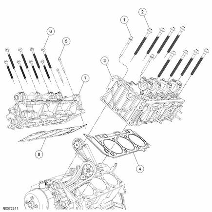
11 34. Remove the LH camshaft sprocket bolt. 35. Remove the LH timing drive cassette upper bolt. 36. NOTE: Remove the camshaft sprocket from the timing chain to gain clearance to remove the cylinder head. NOTE: Hold the timing chain and cassette with a rubber band to aid in removal and to prevent the timing chain from falling into the cylinder block. Remove the LH camshaft sprocket from the timing chain. Install a rubber band around the cassette and the timing chain. Both sides 37. NOTICE: To avoid damage to the timing chain cassette, an assistant will be required to help lift the cylinder head from the vehicle. NOTE: New cylinder head bolts must be installed. They are a torque-to-yield design and cannot be reused. Remove the cylinder heads. - Remove the 10 cylinder head bolts in the sequence shown. Discard all bolts. - Remove and discard the head gasket. 11/17
12 38. NOTICE: Do not use metal scrapers, wire brushes, power abrasive discs or other abrasive means to clean the sealing surfaces. These tools cause scratches and gouges which make leak paths. Clean the cylinder head gasket surfaces with metal surface cleaner. 39. Support the cylinder head on a bench with the head gasket side up. Check the cylinder head distortion and the cylinder block distortion. For additional information, refer to Engine. Installation Both sides 1. Clean the cylinder head bolt holes in the cylinder block. Make sure all coolant, oil or other foreign material is removed. 2. Position the cylinder head gasket on the block. RH side 3. NOTICE: To avoid damage to the timing chain cassette, an assistant will be required to help position the cylinder head in the vehicle. NOTE: New cylinder head bolts must be installed. They are a torque-to-yield design and cannot be reused. Install the cylinder head. Install 8 new 12-mm bolts and tighten in the sequence shown in 2 stages. - Stage 1: Tighten to 12 Nm (106 lb-in). - Stage 2: Tighten to 25 Nm (18 lb-ft). 4. Install 2 new 8-mm bolts. - Tighten to 32 Nm (24 lb-ft). 12/17
13 5. Tighten the eight 12-mm bolts in the sequence shown in 2 stages. - Stage 1: Tighten 90 degrees. - Stage 2: Tighten an additional 90 degrees. 6. NOTE: The camshaft gear must turn freely on the camshaft. DO NOT tighten the bolt at this time. Remove the rubber band. Install the camshaft sprocket and bolt. 7. Install the RH timing drive cassette upper bolt. - Tighten to 10 Nm (89 lb-in). 8. Position the wiring harness bracket and install the bolt. - Tighten to 28 Nm (21 lb-ft). 9. Install the RH exhaust manifold. For additional information, refer to Exhaust Manifold - RH See: Exhaust Manifold > Removal and Replacement > Exhaust Manifold - RH See: Exhaust System. 10. Install the RH inner fender splash shield and the 5 pushpins. 11. Install 2 new wiring harness retainers and attach the wiring harness. 12. Connect the CKP sensor electrical connector. 13. Position the generator bracket and install the 3 bolts. - Tighten to 42 Nm (31 lb-ft). 14. Position the accessory drive belt tensioner and install the bolt. - Tighten to 47 Nm (35 lb-ft). 13/17
14 15. Connect the generator electrical connectors and install the nut. Attach the wiring harness retainers. - Tighten to 12 Nm (106 lb-in). LH side 16. NOTICE: To avoid damage to the timing chain cassette, an assistant will be required to help position the cylinder head in the vehicle. NOTE: New cylinder head bolts must be installed. They are a torque-to-yield design and cannot be reused. Install the cylinder head. Install 8 new 12-mm bolts and tighten in the sequence shown in 2 stages. - Stage 1: Tighten to 12 Nm (106 lb-in). - Stage 2: Tighten to 25 Nm (18 lb-ft). 17. Install 2 new 8-mm bolts. - Tighten to 32 Nm (24 lb-ft). 14/17
15 18. Tighten the eight 12-mm bolts in the sequence shown in 2 stages. - Stage 1: Tighten 90 degrees. - Stage 2: Tighten an additional 90 degrees. 19. NOTE: The camshaft gear must turn freely on the camshaft. DO NOT tighten the bolt at this time. Remove the rubber band. Install the camshaft sprocket and bolt. 20. Install the LH timing drive cassette upper bolt. - Tighten to 12 Nm (106 lb-in). 21. Position the ground strap and install the bolt. - Tighten to 25 Nm (18 lb-ft). 22. Install the LH exhaust manifold. For additional information, refer to Exhaust Manifold - LH See: Exhaust Manifold > Removal and Replacement > Exhaust Manifold - LH See: Exhaust System. 23. NOTE: Apply silicone brake caliper grease and dielectric compound to the inside of the spark plug boots. Position the ignition coil in the engine compartment and connect the spark plug wires to the LH spark plugs. 24. Install the oil level indicator tube and bolt. - Tighten to 10 Nm (89 lb-in). 25. Attach the wiring harness to the LH cylinder head and install the bolt. - Tighten to 10 Nm (89 lb-in). 26. Position the power steering and A/C compressor bracket and install the 4 bolts. - Tighten to 42 Nm (31 lb-ft). Both sides 27. Rotate the accessory drive belt tensioner counterclockwise and install the accessory drive belt. 15/17
16 28. NOTE: The LH and RH camshafts must be retimed when either camshaft is disturbed. NOTE: Install the hydraulic chain tensioners during camshaft timing. Time the camshafts. For additional information, refer to Camshaft Timing See: Camshaft, Engine > Procedures > Camshaft Timing. 29. NOTE: Inspect the thermostat housing O-ring seal. Install a new O-ring seal if necessary. Position the thermostat housing, making sure the bypass hose is connected to the coolant pump, and install the 3 bolts. - Tighten to 11 Nm (97 lb-in). 30. Position the bypass hose clamp. 31. Connect the ECT sensor electrical connector. 32. Position the fuel rail and fuel injector assembly and install the 4 bolts. - Tighten to 23 Nm (17 lb-ft). 33. Connect the spring lock coupling. For additional information, refer to Fuel Delivery and Air Induction. 34. Install the roller followers. For additional information, refer to Camshaft Roller Follower See: Rocker Arm Assembly > Removal and Replacement > Camshaft Roller Follower. 35. Install the cooling fan shroud. For additional information, refer to Cooling System &/or Engine Block Heater. 36. Install the intake manifold. For additional information, refer to Intake Manifold See: Intake Manifold > Removal and Replacement > Intake Manifold See: Intake Manifold. 37. Fill and bleed the engine cooling system. For additional information, refer to Cooling System &/or Engine Block Heater. 16/17
17 2017 ALLDATA, LLC. All Rights Reserv ed. (Version ) 17/17
IN-VEHICLE REPAIR. Cylinder Head. Special Tool(s) Timing Tool, Crankshaft TDC (T97T-6303-A) or. Special Tool(s) equivalent
 Timing Tool, Crankshaft TDC (T97T-6303-A) or. Special Tool(s) equivalent") 303-01A-1 IN-VEHICLE REPAIR Cylinder Head Special Tool(s) Torque Wrench Extension 303-575 (T97T-6256-F) or equivalent Special Tool(s) 303-01A-1 Timing Tool, Crankshaft TDC 303-573 (T97T-6303-A) or equivalent
303-01A-1 IN-VEHICLE REPAIR Cylinder Head Special Tool(s) Torque Wrench Extension 303-575 (T97T-6256-F) or equivalent Special Tool(s) 303-01A-1 Timing Tool, Crankshaft TDC 303-573 (T97T-6303-A) or equivalent
2002 Explorer Sport/Sport Trac Workshop Manual
 Page 1 of 17 SECTION 303-01: Engine 4.0L Single Overhead Camshaft (SOHC) IN-VEHICLE REPAIR Procedure revision date: 07/13/2005 Cylinder Head Special Tool(s) Spark Plug Wire Remover 303-106 (T74P-6666-A)
DISASSEMBLY. Engine. CAUTION: Remove the cylinder heads before removing the crankshaft. Failure to do so can result in engine damage.
 303-01A-1 DISASSEMBLY Engine Special Tool(s) Remover, Crankshaft Vibration Damper 303-101 (T74P-3616-A) Special Tool(s) Crankshaft Socket 303-674 303-01A-1 Remover, Crankshaft Vibration Damper 303-773
 Page 1 of 5 303-01B Engine 3.0L (4V) 2004 Escape IN-VEHICLE REPAIR Procedure revision date: 05/26/2005 Engine Front Cover Material Removal Item Motocraft Metal Surface Cleaner ZC-21 Silicone Gasket and
Intake Components 1117
 Item Part Number Description 1 W705654 Bolt 2 N807309 Bolt (2 req'd) 3 9F460 Bracket 4 N807071 Bolt (5 req'd) 5 9A448 Intake manifold (upper) 6 9E498 Vacuum harness 7 9F792 Fuel injection supply manifold
Engine. Special Tool(s) Adapter for (T97T-6256-A) Adapter for (T97T-6256-D)
 Adapter for (T97T-6256-A) Adapter for (T97T-6256-D)") SECTION 303-01A: Engine 4.0L SOHC 2009 Mustang Workshop Manual ASSEMBLY Procedure revision date: 05/10/2010 Engine Special Tool(s) Adapter for 303-564 303-578 (T97T-6256-A) Adapter for 303-577 303-576
SECTION 303-01A: Engine 4.0L SOHC 2009 Mustang Workshop Manual ASSEMBLY Procedure revision date: 05/10/2010 Engine Special Tool(s) Adapter for 303-564 303-578 (T97T-6256-A) Adapter for 303-577 303-576
 Page 1 of 21 303-01C Engine 5.4L (3V) 2009 F-150 REMOVAL Procedure revision date: 03/26/2009 Cylinder Head Special Tool(s) 3 Jaw Puller 303-D121 or equivalent Compressor, Valve Spring 303-1039 Holding
2010 Transit Connect Workshop Manual. 31. Remove the 3 bolts, thermostat housing and thermostat.
 31. Remove the 3 bolts, thermostat housing and thermostat. 32. Remove the 2 bolts, stud bolt and the A/C compressor. 33. Remove the bolt and the KS. 34. Remove the 8 bolts and the crankcase vent oil separator.
Cylinder Head. Special Tool(s) Compressor, Valve Spring (T93P-6565-AR) Heavy Duty Floor Crane or equivalent
 Compressor, Valve Spring (T93P-6565-AR) Heavy Duty Floor Crane or equivalent") SECTION 303-01C: Engine 5.4L (4V) 2009 Mustang Workshop Manual INSTALLATION Procedure revision date: 04/03/2009 Cylinder Head Special Tool(s) Compressor, Valve Spring 303-452 (T93P-6565-AR) Heavy Duty
SECTION 303-01C: Engine 5.4L (4V) 2009 Mustang Workshop Manual INSTALLATION Procedure revision date: 04/03/2009 Cylinder Head Special Tool(s) Compressor, Valve Spring 303-452 (T93P-6565-AR) Heavy Duty
IN-VEHICLE REPAIR. Timing Drive Components Camshaft Drive Cassette, LH. Special Tool(s) Holding Tool, Camshaft Sprocket (T97T-6256)
 Holding Tool, Camshaft Sprocket (T97T-6256)") 303-01A-1 IN-VEHICLE REPAIR Timing Drive Components Camshaft Drive Cassette, LH 303-01A-1 Special Tool(s) Holding Tool, Camshaft Sprocket 303-564 (T97T-6256) Adapter for 303-564 303-578 (T97T-6256-A) Holding
303-01A-1 IN-VEHICLE REPAIR Timing Drive Components Camshaft Drive Cassette, LH 303-01A-1 Special Tool(s) Holding Tool, Camshaft Sprocket 303-564 (T97T-6256) Adapter for 303-564 303-578 (T97T-6256-A) Holding
2002 Mustang Workshop Manual
 Page 1 of 13 SECTION 303-01B: Engine 4.6L (2V) 2002 Mustang Workshop Manual REMOVAL Procedure revision date: 01/02/2003 Cylinder Heads Special Tool(s) Remover, Crankshaft Vibration Damper 303-009 (T58P-6316-D)
Engine Front Cover. Special Tool(s) Lifting Bracket, Engine (2 required) 303-D087 (D93P-6001-A1) or equivalent. Support Bar, Engine 303-F070
 Lifting Bracket, Engine (2 required) 303-D087 (D93P-6001-A1) or equivalent. Support Bar, Engine 303-F070") SECTION 303-01C: Engine 5.4L (4V) 2009 Mustang Workshop Manual IN-VEHICLE REPAIR Procedure revision date: 07/25/2008 Engine Front Cover Special Tool(s) Lifting Bracket, Engine (2 required) 303-D087 (D93P-6001-A1)
SECTION 303-01C: Engine 5.4L (4V) 2009 Mustang Workshop Manual IN-VEHICLE REPAIR Procedure revision date: 07/25/2008 Engine Front Cover Special Tool(s) Lifting Bracket, Engine (2 required) 303-D087 (D93P-6001-A1)
Engine. Special Tool(s) Compressor, Piston Ring 303-D032 (D81L-6002-C) or equivalent. Compressor, Valve Spring (T93P-6565-AR)
 Compressor, Piston Ring 303-D032 (D81L-6002-C) or equivalent. Compressor, Valve Spring (T93P-6565-AR)") SECTION 303-01C: Engine 5.4L (4V) 2009 Mustang Workshop Manual ASSEMBLY Procedure revision date: 12/12/2008 Engine Special Tool(s) Compressor, Piston Ring 303-D032 (D81L-6002-C) or equivalent Compressor,
SECTION 303-01C: Engine 5.4L (4V) 2009 Mustang Workshop Manual ASSEMBLY Procedure revision date: 12/12/2008 Engine Special Tool(s) Compressor, Piston Ring 303-D032 (D81L-6002-C) or equivalent Compressor,
Cylinder Head. Special Tool(s) 3-Jaw Puller 303-D121 or equivalent. Compressor, Valve Spring
 3-Jaw Puller 303-D121 or equivalent. Compressor, Valve Spring") SECTION 303-01B: Engine 4.6L (3V) 2009 Mustang Workshop Manual REMOVAL Procedure revision date: 03/15/2009 Cylinder Head Special Tool(s) 3-Jaw Puller 303-D121 or equivalent Compressor, Valve Spring 303-1039
SECTION 303-01B: Engine 4.6L (3V) 2009 Mustang Workshop Manual REMOVAL Procedure revision date: 03/15/2009 Cylinder Head Special Tool(s) 3-Jaw Puller 303-D121 or equivalent Compressor, Valve Spring 303-1039
Timing Drive Components Camshaft Timing
 SECTION 303-01B: Engine 4.0L SOHC 1998 Explorer/Mountaineer Workshop Manual IN-VEHICLE REPAIR Procedure revision date: 10/17/2002 Timing Drive Components Camshaft Timing Special Tool(s) Timing Chain Tensioner
2002 Escape Workshop Manual
 SECTION 303-01A: Engine 2.0L Zetec 2002 Escape Workshop Manual IN-VEHICLE REPAIR Procedure revision date: 10/25/2004 Timing Belt Special Tool(s) Crankshaft TDC Timing Peg 303-574 (T97P-6000-A) Camshaft
1999 F-150/250 Workshop Manual
 Page 1 of 8 SECTION 303-01B: Engine 4.6L and 5.4L IN-VEHICLE REPAIR Procedure revision date: 02/03/1999 Intake Manifold Lightning Removal WARNING: Do not smoke or carry lighted tobacco or open flame of
2000 Econoline Workshop Manual. 3. Install the upper intake manifold. 2. NOTE: Tighten the bolts in two stages.
 2. NOTE: Tighten the bolts in two stages. Tighten the bolts in the sequence shown. Stage 1: Tighten to 2 Nm (18 lb-in). Stage 2: Tighten to 10 Nm (89 lb-in). 3. Install the upper intake manifold. Position
ASSEMBLY. Engine. Special Tool(s) Installer, Crankshaft Vibration Damper (T74P-6316-B) Special Tool(s)
 Installer, Crankshaft Vibration Damper (T74P-6316-B) Special Tool(s)") 303-01A-1 ASSEMBLY Engine Special Tool(s) Tensioner, Timing Chain 303-571 (T97T-6K254-A) Special Tool(s) 303-01A-1 Installer, Crankshaft Vibration Damper 303-102 (T74P-6316-B) Holding Tool, Camshaft Sprocket
303-01A-1 ASSEMBLY Engine Special Tool(s) Tensioner, Timing Chain 303-571 (T97T-6K254-A) Special Tool(s) 303-01A-1 Installer, Crankshaft Vibration Damper 303-102 (T74P-6316-B) Holding Tool, Camshaft Sprocket
10/20/ Ford E 250 Engine Mechanical > Engine, 4.6L and 5.4L > IN VEHICLE REPAIR > Intake Manifold 5.4L
 2005 Ford E 250 : Engine Mechanical > Engine, 4.6L and 5.4L > IN VEHICLE REPAIR > Intake Manifold 5.4L Intake Manifold 5.4L Listen SECTION 303 01A: Engine 4.6L and 5.4L 2005 E Series Workshop Manual IN
2007 Ford Freestyle SEL
 Fig. 279: Exploded View Of Engine Heads, Intake & Exhaust Components Item Part Number Description 1 9D475 Exhaust gas recirculation (EGR) system module 2 9D477 EGR module tube 3 9F485 RH exhaust manifold
2006 Expedition/Navigator Workshop Manual
 7. Remove the RH variable camshaft timing (VCT) oil control solenoid. For additional information, refer to Section 303-14. 8. Remove the RH ignition coils. For additional information, refer to Section
Zoom and Print Options
 Vehicle» Engine, Cooling and Exhaust» Engine» Cylinder Head Assembly» Service and Repair» Procedures» Removal Cylinder Heads http://repair.alldata.com/alldata/article/display.action?componentid=65&itypeid=376&nonstandardid=682956&vehicleid=45317&windowname=maina
REMOVAL. Cylinder Head. All cylinder heads. 1. Remove the engine. For additional information, refer to Engine in this section.
 303-01B-1 303-01B-1 REMOVAL Cylinder Head Material Item Specification Special Tool(s) Motorcraft Metal Surface Prep Modular Engine Lift Bracket ZC-31 303-F047 (014-00073) or equivalent Silicone Gasket
IN-VEHICLE REPAIR. Upper Intake Manifold
 303-01-1 Engine 3.9L and 4.2L 303-01-1 IN-VEHICLE REPAIR Upper Intake Manifold Special Tool(s) Remover, Spark Plug Wire 303-106 (T74P-6666-A) Material Item Silicone Brake Caliper Grease and Dielectric
1983 BMW 320i. 1.8L 4-CYL 1983 Engines - 1.8L 4-Cylinder Engines - 1.8L 4-Cylinder
 ENGINE IDENTIFICATION 1.8L 4-CYL 1983 Engines - 1.8L 4-Cylinder For engine repair procedures not covered in this article, see ENGINE OVERHAUL PROCEDURES - GENERAL INFORMATION article in the GENERAL INFORMATION
IN-VEHICLE REPAIR. Engine Front Cover
 303-01A-1 IN-VEHICLE REPAIR Engine Front Cover Material Item Specification 303-01A-1 Special Tool(s) SAE 5W-20 Premium WSS-M2C930-A Synthetic Blend Motor Oil Alignment Plate, Camshaft XO-5W20-QSP (in Canada
 Page 1 of 8 303-01A Engine 2.3L 2007 Escape/Mariner/Escape Hybrid/Mariner Hybrid IN-VEHICLE REPAIR Procedure revision date: 10/05/2008 Cylinder Head Special Tool(s) Alignment Plate, Camshaft 303-465 (T94P-6256-CH)
2001 Lincoln LS Workshop Manual
 Page 1 of 10 SECTION 303-01B: Engine 3.9L 2001 Lincoln LS Workshop Manual IN-VEHICLE REPAIR Procedure revision date: 05/16/2000 Intake Manifold Removal 1. Disconnect the battery ground cable. For additional
DISASSEMBLY Procedure revision date: 11/22/2001
 Page 1 of 31 Evan Groenke From: Daniel Lelovic [dlelovic@rogers.com] Sent: May 8, 2005 12:06 PM To: 'Evan Groenke' Subject: 2.5 L Engine Disassembly SECTION 303-01B: Engine 2.5L 2000 Contour/Mystique Workshop
 Page 1 of 14 Oil Pan Removal & Installation 4.2L Engine 4WD Vehicles To Remove: 1. Before servicing the vehicle refer to the precautions at the beginning of this section. 2. Raise and support the vehicle.
Zoom and Print Options
 Vehicle» Engine, Cooling and Exhaust» Engine» Cylinder Head Assembly» Valve Cover» Service and Repair» Procedures» RH Valve Cover RH Removal 1. Disconnect the battery ground cable. 2. Remove the air cleaner
1999 E-Series Workshop Manual
 http://www.fordservicecontent.com/pubs/content/~wsxm/~mus~len/21/sxm31c16.h... Page 1 of 3 SECTION 303-01C: Engine 6.8L 1999 E-Series Workshop Manual IN-VEHICLE REPAIR Procedure revision date: 06/30/1998
2011 Mercury Grand Marquis LS
 Fig. 6: Locating Intake Manifold Crash Bracket With Tie Strap 24. Remove the intake manifold crash bracket bolt. 25. Disconnect the fuel rail pressure and temperature sensor vacuum and electrical connectors.
SECTION C Engine 5.4L (3V)
") 303-01C-i Engine 5.4L (3V) 303-01C-i SECTION 303-01C Engine 5.4L (3V) CONTENTS PAGE IN-VEHICLE REPAIR Engine Front Cover... 303-01C-2 303-01C-2 Engine 5.4L (3V) 303-01C-2 IN-VEHICLE REPAIR Engine Front
303-01C-i Engine 5.4L (3V) 303-01C-i SECTION 303-01C Engine 5.4L (3V) CONTENTS PAGE IN-VEHICLE REPAIR Engine Front Cover... 303-01C-2 303-01C-2 Engine 5.4L (3V) 303-01C-2 IN-VEHICLE REPAIR Engine Front
1 of 14 11/19/ :45 AM
 1 of 14 11/19/2016 11:45 AM 6F35 Digital Transmission Range (TR) Sensor Removal All vehicles 1. With the vehicle in NEUTRAL, position it on a hoist. 3.0L engine 2. Remove the Air Cleaner (ACL) outlet pipe.
IN-VEHICLE REPAIR. Engine Front Cover
 303-01B-1 IN-VEHICLE REPAIR Engine Front Cover Material Item Specification 303-01B-1 Special Tool(s) Motorcraft SAE 5W-20 WSS-M2C930-A Premium Synthetic Blend 3-Jaw Puller Motor Oil 303-D121 XO-5W20-QSP
Engine Front Cover. Special Tool(s) 3-Jaw Puller 303-D121 or equivalent. Installer, Front Cover Oil Seal (T88T-6701-A)
 3-Jaw Puller 303-D121 or equivalent. Installer, Front Cover Oil Seal (T88T-6701-A)") SECTION 303-01B: Engine 4.6L (3V) 2009 Mustang Workshop Manual IN-VEHICLE REPAIR Procedure revision date: 05/23/2008 Engine Front Cover Special Tool(s) 3-Jaw Puller 303-D121 or equivalent Installer, Front
SECTION 303-01B: Engine 4.6L (3V) 2009 Mustang Workshop Manual IN-VEHICLE REPAIR Procedure revision date: 05/23/2008 Engine Front Cover Special Tool(s) 3-Jaw Puller 303-D121 or equivalent Installer, Front
1990 Buick Electra Limited
 4. To install remaining components, reverse removal procedure. Coat rocker arm bolts with GM Threadlock (12345493) prior to installation. Fig. 3: Cylinder Head Bolt Tightening Sequence FRONT CRANKSHAFT
DISASSEMBLY. Engine. Special Tool(s) Locking Tool, Camshaft Phaser Sprocket Special Tool(s)
 Locking Tool, Camshaft Phaser Sprocket Special Tool(s)") 303-01B-1 DISASSEMBLY Engine Special Tool(s) Remover, Crankshaft Rear Slinger 303-514 (T95P-6701-AH) Special Tool(s) 303-01B-1 Locking Tool, Camshaft Phaser Sprocket 303-1046 Remover, Crankshaft Rear Seal
303-01B-1 DISASSEMBLY Engine Special Tool(s) Remover, Crankshaft Rear Slinger 303-514 (T95P-6701-AH) Special Tool(s) 303-01B-1 Locking Tool, Camshaft Phaser Sprocket 303-1046 Remover, Crankshaft Rear Seal
1 of 10 2/10/2017 5:20 PM
 1 of 10 2/10/2017 5:20 PM Crankshaft Pulley Removal NOTICE: Do not loosen or remove the crankshaft pulley bolt without first installing the special tools as instructed in this procedure. The crankshaft
Torque Guidelines (Z 22 SE)
") Page 1 of 14 Torque Guidelines (Z 22 SE) No. Designation Nm 1 Retaining bolts, coolant pump sprocket to coolant pump 2 Retaining bolts, balancer shaft timing chain guide rail to 3 Retaining bolts, balancer
Page 1 of 14 Torque Guidelines (Z 22 SE) No. Designation Nm 1 Retaining bolts, coolant pump sprocket to coolant pump 2 Retaining bolts, balancer shaft timing chain guide rail to 3 Retaining bolts, balancer
2003 Taurus/Sable Workshop Manual
 Page 1 of 24 SECTION 303-01A: Engine 3.0L (2V) ASSEMBLY 2003 Taurus/Sable Workshop Manual Engine Special Tool(s) Piston Ring Compressor 303- D032 (D81L-6002-C) Camshaft Bearing Set 303-017 (T65L-6250-A)
2002 Crown Victoria/Grand Marquis Workshop Manual
 Page 1 of 24 SECTION 303-01: Engine 2002 Crown Victoria/Grand Marquis Workshop Manual INSTALLATION Procedure revision date: 01/02/2003 Cylinder Heads Special Tool(s) Installer, Crankshaft Vibration Damper
PARTIAL ENGINE ASSY (2TR FE)
") COMPONENTS 147 1421Z01 Clip Hood Subassy x9 Radiator Support to Frame Seal LH 30 (306, 22) 30 (306, 22) Fan and Generator V Belt 5.0 (51, 44 in. lbf) Fan Shroud Fan Pulley Fan w/ Fluid Coupling PRE RUNNER
COMPONENTS 147 1421Z01 Clip Hood Subassy x9 Radiator Support to Frame Seal LH 30 (306, 22) 30 (306, 22) Fan and Generator V Belt 5.0 (51, 44 in. lbf) Fan Shroud Fan Pulley Fan w/ Fluid Coupling PRE RUNNER
IN-VEHICLE SERVICE. Engine Components
 file://c:\tso\tsocache\vdtom_5368\svk~us~en~file=svk31a14.htm~gen~ref.htm Page 1 of 10 Section 03-01A: Engine, 2.3L I-4 IN-VEHICLE SERVICE 1997 Ranger Workshop Manual Engine Components The views shown
2001 Chrysler Truck PT Cruiser L4-2.4L VIN B Copyright 2013, ALLDATA Page 1
 2001 Chrysler Truck PT Cruiser L4-2.4L VIN B Copyright 2013, ALLDATA 10.52 Page 1 Timing Belt: Service and Repair Timing Belt REMOVAL 1. Disconnect negative battery cable. 2. Raise vehicle on hoist. Remove
2001 Dodge Dakota ENGINES 4.7L V8
 FRONT COVER Removal & Installation 1. Disconnect negative battery cable. Remove drive belt. Remove A/C compressor mounting bolts, and position compressor aside. Drain cooling system. Remove radiator hoses.
Engine. Special Tool(s) Compressor, Valve Spring (T97P-6565-AH) Compressor Spacer, Valve Spring (T91P-6565-AH)
 Compressor, Valve Spring (T97P-6565-AH) Compressor Spacer, Valve Spring (T91P-6565-AH)") Page 1 of 41 SECTION 303-01A: Engine 5.4L (2V) 2000 F-Super Duty 250-550/Excursion/F-53 Motorhome Chassis Workshop Manual ASSEMBLY Procedure revision date: 04/04/2003 Engine Special Tool(s) Compressor,
Page 1 of 41 SECTION 303-01A: Engine 5.4L (2V) 2000 F-Super Duty 250-550/Excursion/F-53 Motorhome Chassis Workshop Manual ASSEMBLY Procedure revision date: 04/04/2003 Engine Special Tool(s) Compressor,
SECTION B Engine 5.0L (4V)
") 303-01B-i Engine 5.0L (4V) 303-01B-i SECTION 303-01B Engine 5.0L (4V) CONTENTS PAGE SPECIFICATIONS... 303-01B-2 303-01B-2 Engine 5.0L (4V) 303-01B-2 SPECIFICATIONS Material Motorcraft Metal Surface Prep
303-01B-i Engine 5.0L (4V) 303-01B-i SECTION 303-01B Engine 5.0L (4V) CONTENTS PAGE SPECIFICATIONS... 303-01B-2 303-01B-2 Engine 5.0L (4V) 303-01B-2 SPECIFICATIONS Material Motorcraft Metal Surface Prep
 Page 1 of 8 Section 03-01: Engine, 4.6L IN-VEHICLE SERVICE 1994 Town Car/Crown Victoria/Grand Marquis Workshop Manual Oil Pan and Oil Pump Screen Cover and Tube Town Car Removal 1. Disconnect battery ground
DESCRIPTION AND OPERATION
 303-01B-10 Engine 3.0L 303-01B-10 DESCRIPTION AND OPERATION Upper Engine Components G72932 en 303-01B-11 Engine 3.0L 303-01B-11 DESCRIPTION AND OPERATION (Continued) Item Part Number Description 1 9H589
file://c:\program Files\tsocache\OFFICE_5416\SY1~us~en~file=SY131B46.htm~gen~ref...
 Page 1 of 41 SECTION 303-01B: Engine 4.6L and 5.4L 2000 F-150 Workshop Manual ASSEMBLY Procedure revision date: 01/27/2004 Engine 4.6L Special Tool(s) Compressor, Valve Spring 303-567 (T97P-6565-AH) Compressor
1991 Nissan 240SX. 2.4L 4-CYL - VINS [F,M,S] 1991 ENGINES Nissan 2.4L 4-Cylinder
![1991 Nissan 240SX. 2.4L 4-CYL - VINS [F,M,S] 1991 ENGINES Nissan 2.4L 4-Cylinder](/thumbs/95/123571962.jpg "1991 Nissan 240SX. 2.4L 4-CYL - VINS [F,M,S] 1991 ENGINES Nissan 2.4L 4-Cylinder") NOTE: Use illustration for component reference. See Fig. 7. 1. Remove spark plug wires. Set No. 1 piston at TDC on its compression stroke. Remove vacuum hoses, electrical harnesses, connectors, and harness
NOTE: Use illustration for component reference. See Fig. 7. 1. Remove spark plug wires. Set No. 1 piston at TDC on its compression stroke. Remove vacuum hoses, electrical harnesses, connectors, and harness
 Page 1 of 9 SECTION 303-01B: Engine 2.0L SPI 2002 Focus Workshop Manual ASSEMBLY Procedure revision date: 12/14/2000 Engine Special Tool(s) Crankshaft Rear Seal Pilot 303-329 (T88P-6701-B2) Crankshaft
2000 Nissan Altima SE
 Removal 1. Release fuel pressure. See FUEL PRESSURE RELEASE. Drain coolant from radiator and cylinder block. Drain engine oil. Disconnect all necessary coolant hoses, electrical connectors, vacuum hoses,
NOTE: Do not disassemble upper intake manifold from lower intake manifold unless replacement of one of the components is necessary.
 Fig. 2: Lower Intake Manifold Bolt Tightening Sequence INTAKE MANIFOLD (UPPER) NOTE: Do not disassemble upper intake manifold from lower intake manifold unless replacement of one of the components is necessary.
10 +/- 2 degrees before top dead center (BTDC)
") 1996 Ford Contour L4-122 2.0L DOHC VIN 3 SFI Ignition Timing Adjustments Base ignition timing is referenced to the position of the crankshaft position sensor. It is set at 10 +/- 2 degrees before top dead
1996 Ford Contour L4-122 2.0L DOHC VIN 3 SFI Ignition Timing Adjustments Base ignition timing is referenced to the position of the crankshaft position sensor. It is set at 10 +/- 2 degrees before top dead
ENGINE ASSEMBLY. COMPONENTS (Part 1)
") 1 of 32 ENGINE ASSEMBLY COMPONENTS (Part 1) 2 of 32 COMPONENTS (Part 2) 3 of 32 COMPONENTS (Part 3) 4 of 32 COMPONENTS (Part 4) 5 of 32 COMPONENTS (Part 5) 6 of 32 COMPONENTS (Part 6) 7 of 32 COMPONENTS
1 of 32 ENGINE ASSEMBLY COMPONENTS (Part 1) 2 of 32 COMPONENTS (Part 2) 3 of 32 COMPONENTS (Part 3) 4 of 32 COMPONENTS (Part 4) 5 of 32 COMPONENTS (Part 5) 6 of 32 COMPONENTS (Part 6) 7 of 32 COMPONENTS
Lower Intake Manifold Replacement
 Lower Intake Manifold Replacement Removal Procedure 1. Turn OFF all the lamps and the accessories. 2. Ensure the ignition switch is in the OFF position. 3. Disconnect the negative battery cable from the
WARNING: ALWAYS relieve fuel pressure before disconnecting any fuel related component. DO NOT allow fuel to contact engine or electrical components.
 4.0L V8 - VINS [K,U] Selected Block 1990 Lexus LS 400 For Lextreme Powertrain 2020 S. Hacienda Blvd. # D Hacienda Heights California 91745 Copyright 1998 Mitchell Repair Information Company, LLC Friday,
1 of 12 11/20/2016 9:32 PM
 1 of 12 11/20/2016 9:32 PM Caution: After removing timing chain, do not turn crankshaft and camshaft separately, or valves will strike piston heads. Apply new engine oil to the sliding surfaces when Installing
COMPONENT LOCATOR > DISASSEMBLED VIEWS
 Page 1 of 45 2006 Pontiac Grand Prix 3.8L Eng Base Service Manual: ENGINE MECHANICAL - 3.8L COMPONENT LOCATOR > DISASSEMBLED VIEWS Fig 1: Engine Block Component Views Callout Component Name 100 Engine
The following tools will be required to perform this new service procedure outlined in this bulletin:
 The following new service information outlined in this bulletin will aid technicians in removal and installation of the cylinder head without the removal of the front engine cover. The new service procedure
2003 Nissan-Datsun Truck Frontier 4WD V6-3.3L (VG33E)
") 1 of 15 8/7/2016 2:34 PM 2003 Nissan-Datsun Truck Frontier 4WD V6-3.3L (VG33E) Vehicle» Engine, Cooling and Exhaust» Engine» Cylinder Head Assembly» Service and Repair» Removal and Installation 2 of 15
1 of 15 8/7/2016 2:34 PM 2003 Nissan-Datsun Truck Frontier 4WD V6-3.3L (VG33E) Vehicle» Engine, Cooling and Exhaust» Engine» Cylinder Head Assembly» Service and Repair» Removal and Installation 2 of 15
1991 Volkswagen Vanagon Syncro
 corner of radiator. See Fig. 1. Fig. 1: Bleeding Cooling System 2. Open bleeder valve in engine compartment (turn counterclockwise). See Fig. 1. Fill expansion tank until full. Start and run engine at
3/6/2017 Timing Chain Service and Repair, Removal and Replacement: Valve Timing, Installing and Adjusting
 Valve timing, adjusting Special tools and equipment - T10068 Camshaft bar - T10069 Counter support - VAG 1331 Torque wrench (5-50 Nm) - VAG 1332 Torque wrench (40-200 Nm) - AMV 174 004 01 Sealing compound
SECTION C Engine 5.4L (4V)
") 303-01C-i Engine 5.4L (4V) 303-01C-i SECTION 303-01C Engine 5.4L (4V) CONTENTS PAGE SPECIFICATIONS... 303-01C-2 303-01C-2 Engine 5.4L (4V) 303-01C-2 SPECIFICATIONS Material Motorcraft Metal Surface Prep
303-01C-i Engine 5.4L (4V) 303-01C-i SECTION 303-01C Engine 5.4L (4V) CONTENTS PAGE SPECIFICATIONS... 303-01C-2 303-01C-2 Engine 5.4L (4V) 303-01C-2 SPECIFICATIONS Material Motorcraft Metal Surface Prep
IN-VEHICLE SERVICING > VALVE COVER - RH
 Page 1 of 20 Service Manual: ENGINE - 5.4L (3V)- F-150 & MARK LT IN-VEHICLE SERVICING > VALVE COVER - RH 2008 Ford Pickup 5.4L Eng F150 Material Item Specification Motorcraft Metal Surface Prep ZC-31 PAG
Crankshaft Rear Seal with Retainer Plate
 SECTION 303-01C: Engine 5.4L (4V) 2009 Mustang Workshop Manual IN-VEHICLE REPAIR Procedure revision date: 07/25/2008 Crankshaft Rear Seal with Retainer Plate Special Tool(s) Installer, Crankshaft Rear
Timing Chain Renew ( ) Renew. Section Title. Special Tools. Proprietary Tools Scraper Engine support bar
 Renew. Section Title. Special Tools. Proprietary Tools Scraper Engine support bar") Timing Chain Renew ( 34 0) Special Tools 40 400 40 Engine support bar 40 0 Adaptor for -40 40 03 Adaptor for -40 Proprietary Tools Scraper Workshop Equipment Transmission jack Materials Cable ties Sealer
Timing Chain Renew ( 34 0) Special Tools 40 400 40 Engine support bar 40 0 Adaptor for -40 40 03 Adaptor for -40 Proprietary Tools Scraper Workshop Equipment Transmission jack Materials Cable ties Sealer
PARTIAL ENGINE ASSY (2ZZ GE)
") COMPONENTS 14189 140R701 7.0 (71, 62 in. lbf) Cylinder Head Cover No. 2 19 (194, 14) Radiator Support Upper 19 (194, 14) Radiator Hose Inlet Cruise Control Actuator Assy 6.0 (61, 53 in. lbf) Radiator Assy
COMPONENTS 14189 140R701 7.0 (71, 62 in. lbf) Cylinder Head Cover No. 2 19 (194, 14) Radiator Support Upper 19 (194, 14) Radiator Hose Inlet Cruise Control Actuator Assy 6.0 (61, 53 in. lbf) Radiator Assy
2012 Kia Soul L4 2.0L
 2012 Kia Soul L4 2.0L Vehicle» Engine, Cooling and Exhaust» Engine» Timing Chain» Service and Repair» Repair Procedures» Part 1 Removal Engine removal is not required for this procedure. CAUTION: Use fender
2010 Explorer, Mountaineer, Explorer Sport Trac Workshop Manual. IN-VEHICLE REPAIR Procedure revision date: 06/11/2009
 SECTION 303-01B: Engine - 4.6L 2010 Explorer, Mountaineer, Explorer Sport Trac Workshop (3V) Manual IN-VEHICLE REPAIR Procedure revision date: 06/11/2009 Engine Lubrication Components - Exploded View Brackets,
Intake Manifold: Service and Repair Removal
 1992 Toyota Truck Pickup 2WD V6-180.5 2959cc 3.0L SOHC (3VZ-E) Copyright 2013, ALLDATA 10.52 Page 1 Intake Manifold: Service and Repair Removal NOTE: If removing and later reinstalling the fluid coupling
Timing Chain - Renew ( )
") «Scorpio '95 Table of Contents» «Section 21: Engine» «Subsection 21-05: 2,9 V6 24V Cosworth Engine» «REMOVAL AND INSTALLATION» Timing Chain - Renew (21 314 0) Special Tools 21-140-01Adaptor for 21-140
«Scorpio '95 Table of Contents» «Section 21: Engine» «Subsection 21-05: 2,9 V6 24V Cosworth Engine» «REMOVAL AND INSTALLATION» Timing Chain - Renew (21 314 0) Special Tools 21-140-01Adaptor for 21-140
PARTIAL ENGINE ASSY COMPONENTS. Clip. Radiator Grille. Clip. Front Bumper Cover. Engine Under Cover LH. N m (kgf cm, ft lbf) : Specified torque
 : Specified torque") ENGINE MECHANICAL 1417 COMPONENTS 141FP01 Radiator Grille Front Bumper Cover Engine Under Cover RH Engine Under Cover LH A79361 962 1418 ENGINE MECHANICAL Heater Outlet Water Hose 7.0 (71, 62 in. lbf)
ENGINE MECHANICAL 1417 COMPONENTS 141FP01 Radiator Grille Front Bumper Cover Engine Under Cover RH Engine Under Cover LH A79361 962 1418 ENGINE MECHANICAL Heater Outlet Water Hose 7.0 (71, 62 in. lbf)
Disconnect the breather tube from the air cleaner outlet duct.
 Disconnect the breather tube from the air cleaner outlet duct. Disconnect the IAT sensor harness connector. Remove the air cleaner outlet duct retaining wingnut. Separate the air cleaner outlet duct from
Cylinder head, removing and
 Page 1 of 35 15-2 Cylinder head, removing and installing Note: Replace cylinder head bolts. Always replace self-locking nuts, bolts as well as gaskets and O-rings. After installing a replacement cylinder
Valve Cover - RH Material
 1 of 5 5/15/2015 8:06 AM Valve Cover - RH Material 2 of 5 5/15/2015 8:06 AM 3 of 5 5/15/2015 8:06 AM Removal CAUTION: During engine repair procedures, cleanliness is extremely important. Any foreign material,
REMOVAL & INSTALLATION
 REMOVAL & INSTALLATION CAUTION: This application is an interference engine. Do not rotate camshaft or crankshaft when timing belt is removed, or engine damage may occur. TIMING BELT Removal 1. Disconnect
1999 Nissan Altima GLE
 TIMING CHAIN CAUTION: If cylinder head is installed and timing chain is disconnected, DO NOT rotate camshaft or crankshaft; valves will contact pistons, resulting in bent valves. NOTE: Following procedure
MANUFACTURER'S SUGGESTED SCHEDULED MAINTENANCE
 1. Disconnect negative battery cable. Drain cooling system. Remove front strut bar and strut brackets, if equipped. 2. Disconnect Intake Air Temperature (IAT) sensor harness connector. Remove air cleaner
Chrysler 2.0L DOHC timing belt procedure REMOVAL
 Chrysler 2.0L DOHC timing belt procedure REMOVAL CAUTION: Camshaft or crankshaft should not be rotated after timing belt is removed. Damage to valve components may occur. Always align timing marks before
TORQUE SPECIFICATIONS
 TORQUE SPECIFICATIONS TORQUE SPECIFICATIONS Application Ft. Lbs. (N.m) A/C Compressor Bracket Bolts Upper Vertical Bolt 16-21 (22-29) Horizontal Bolts 32-43 (43-58) A/C Compressor-To-Bracket Bolts 32-43
 Page 1 of 75 303-01D Engine - 5.2L 32V Ti-VCT 2016 Mustang Assembly Procedure revision date: 12/15/2016 Special Tool(s) / General Equipment Engine Base Part Number: 6L084 205-142 (T80T-4000-J) Installer,
1998 F-150/250 Workshop Manual
 Page 1 of 13 SECTION 303-01B: Engine 4.6L and 5.4L 1998 F-150/250 Workshop Manual IN-VEHICLE REPAIR Procedure revision date: 03/07/2000 Intake Manifold Removal WARNING: Do not smoke or carry lighted tobacco
3/13/ :32 AM. NOTICE: Do not disconnect the hose.
 1 of 25 REPLACEMENT 1. REMOVE HOOD SUB-ASSEMBLY 2. REMOVE FRONT WHEEL RH 3. REMOVE ENGINE UNDER COVER LH 4. REMOVE ENGINE UNDER COVER RH 5. REMOVE FRONT FENDER APRON SEAL RH 6. DRAIN ENGINE OIL a. Install
Distributor Replacement
 Page 1 of 11 2002 Chevrolet Chevy K Silverado - 4WD Sierra, Silverado (VIN C/K) Service Manual Document ID: 690165 Distributor Replacement Removal Procedure Notice: There are two procedures available to
11/29/2017 Engine Cooling - Coolant Pump - Removal and Installation 2010 Ford Edge MotoLogic Engine Cooling 2010 Edge, MKX
 2010 Edge Report a problem with this article 303-03 Engine Cooling 2010 Edge, MKX REMOVAL AND INSTALLATION Procedure revision date: 10/04/2010 Coolant Pump Special Tool(s) Camshaft Holding Tool 303-1248
Engine Dismantle and Assemble ( )
") Engine Dismantle and Assemble ( 34 8) Special Tools 5 053 Slide hammer 47 Vibration damper remover 47 5053 00 Splined head socket, cylinder head bolts 87 Mounting stand with geared drive 00 059C Installer
Engine Dismantle and Assemble ( 34 8) Special Tools 5 053 Slide hammer 47 Vibration damper remover 47 5053 00 Splined head socket, cylinder head bolts 87 Mounting stand with geared drive 00 059C Installer
2004 F-150 Workshop Manual
 Page 1 of 8 SECTION 303-01B: Engine 5.4L (3V) 2004 F-150 Workshop Manual REMOVAL Procedure revision date: 02/10/2004 Engine Printable View (943 KB) Special Tool(s) Modular Engine Lift Bracket 303-F047
REMOVAL. 5. REMOVE OIL DIPSTICK GUIDE (a) Remove the bolt, dipstick guide and engine wire bracket. (b) Remove the O ring from the dipstick guide.
 Remove the bolt, dipstick guide and engine wire bracket. (b) Remove the O ring from the dipstick guide.") EM34 ENGINE MECHANICAL (2RZFE, 3RZFE) P23426 EM1MY01 REMOVAL 1. DRAIN ENGINE COOLANT 2. DISCONNECT THESE CABLES: (a) Disconnect the accelerator cable from the throttle body. A/T: Disconnect the throttle
EM34 ENGINE MECHANICAL (2RZFE, 3RZFE) P23426 EM1MY01 REMOVAL 1. DRAIN ENGINE COOLANT 2. DISCONNECT THESE CABLES: (a) Disconnect the accelerator cable from the throttle body. A/T: Disconnect the throttle
FULL BORE PERFORMANCE EXHAUST MANIFOLDS F-150 ECOBOOST 3.5L
 2018-01-15 FORD F150 ECOBOOST 3.5L FULL BORE PERFORMANCE MANIFOLD SET (PART #500101X) 1 FULL BORE PERFORMANCE EXHAUST MANIFOLDS F-150 ECOBOOST 3.5L INSTALLATION INSTRUCTIONS 2011-2012 FORD F150 3.5L ECOBOOST
Vehicle Level Engine, Cooling and Exhaust Engine Cylinder Head Assembly Service and Repair. Service and Repair
 Page 1 of 7 Home Account Contact ALLDATA Log Out Help BILL SEIDLES MITSUBISHI Select Vehicle New TSBs Technician's Reference Component Search: OK 2001 Pontiac Sunfire L4-2.2L VIN 4 Conversion Calculator
SECTION C Engine 5.4L (4V)
") 303-01C-i Engine 5.4L (4V) 303-01C-i SECTION 303-01C Engine 5.4L (4V) CONTENTS PAGE IN-VEHICLE REPAIR Timing Drive Components... 303-01C-2 303-01C-2 Engine 5.4L (4V) 303-01C-2 IN-VEHICLE REPAIR Timing
303-01C-i Engine 5.4L (4V) 303-01C-i SECTION 303-01C Engine 5.4L (4V) CONTENTS PAGE IN-VEHICLE REPAIR Timing Drive Components... 303-01C-2 303-01C-2 Engine 5.4L (4V) 303-01C-2 IN-VEHICLE REPAIR Timing
REMOVAL & INSTALLATION
 REMOVAL & INSTALLATION TIMING BELT Removal 1. Disconnect negative battery cable. Rotate engine clockwise and position cylinder No. 1 on TDC of compression stroke. Ensure "O" mark on crankshaft pulley aligns
 ALLDATA Online - 1997 Ford Truck F 150 2WD Pickup V8-5.4L SOHC VIN L - Servi... Page 1 of 22 Home Account Contact ALLDATA Log Out Help BILL SEIDLES MITSUBISHI Select Vehicle New TSBs Technician's Reference
2001 Escort Workshop Manual
 Page 1 of 6 SECTION 303-01B: Engine 2.0L Zetec 2001 Escort Workshop Manual IN-VEHICLE REPAIR Procedure revision date: 10/26/2004 Timing Drive Components Timing Belt Special Tool(s) Crankshaft TDC Timing
Cylinder Head Replacement
 CYLINDER HEAD REPLACEMENT (EN... CYLINDER HEAD REPLACEMENT (ENGINE MECHANICAL - 1.6L) Document ID# 1430093 Cylinder Head Replacement Tools Required J 45059 Angle Meter KM-470-B Angular Torque Gauge J 42492-A