Zoom and Print Options
|
|
|
- Madison Lyons
- 6 years ago
- Views:
Transcription

1 Vehicle» Engine, Cooling and Exhaust» Engine» Service and Repair» Removal and Replacement» Engine Replacement Engine Replacement ^ Tools Required - J Hose Clamp Pliers Removal Procedure 1. Remove the hood. 2. Disconnect the battery negative cable. 3. Remove the fuel injector sight shield. 4. Disconnect the vacuum brake booster hose from the vacuum connections and position aside. 5. Disconnect the fuel feed and return lines from the fuel rail and secure to the air inlet grille. 6. Remove the Evaporative Emission (EVAP) canister purge valve solenoid and secure the hose to the air inlet grille. 7. Push the lock release and remove the cruise control cable from the throttle body bracket and lever. 8. Disconnect the electrical connector from the cruise control module. 1/30
2 9. Remove the retaining nuts (2) and the cruise control module (1) from the mounting studs. Caution: In order to avoid possible injury or vehicle damage, always replace the accelerator control cable with a NEW cable whenever you remove the engine from the vehicle. In order to avoid cruise control cable damage, position the cable out of the way while you remove or install the engine. Do not pry or lean against the cruise control cable and do not kink the cable. You must replace a damaged cable. 10. Remove the accelerator control cable. 11. Remove the drive belt. 12. Raise and support the vehicle. 2/30

3 13. Remove the bolt securing both the battery negative cable and the engine harness ground lead to the engine block. 3/30
 ^ The oil level sensor (7) 15. Disconnect the wiring harness from the harness clip at the rear of the A/C compressor. 16. Remove the torque converter cover. 17. Remove the starter motor. 18.")
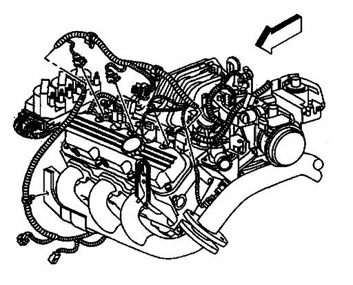
4 14. Disconnect the wiring harness connectors from the following components: ^ The A/C compressor clutch (1) ^ The A/C pressure sensor (2) ^ The knock sensor #1 (3) ^ The engine coolant block heater (4) ^ The oil level sensor (7) 15. Disconnect the wiring harness from the harness clip at the rear of the A/C compressor. 16. Remove the torque converter cover. 17. Remove the starter motor. 18. Remove the bolts securing the flywheel to the torque converter. 4/30


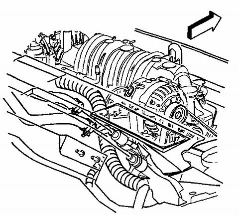
5 19. Disconnect and secure the following wiring harness electrical connectors to the cowl: ^ The knock sensor #2 located behind the right exhaust manifold ^ The oil pressure sensor (2) ^ The Vehicle Speed Sensor (VSS) (3) 5/30
6 20. Remove the 2 bolts securing the transaxle brace to the transaxle. Caution: Always wear protective goggles and gloves when removing exhaust parts as failing rust and sharp edges from worn exhaust components could result in serious personal injury. 21. Remove the 2 nuts attaching the exhaust manifold pipe to the right exhaust manifold. 22. Remove the exhaust manifold pipe from the right exhaust manifold studs, allowing it to rest on top of the power steering gear heat shield. 23. Remove the gasket. Do not reuse the gasket. 24. Remove the right front fascia extension. 6/30

7 25. Remove the front A/C compressor mounting nuts. 26. Remove the rear A/C compressor mounting bolt. 27. Slide the A/C compressor forward off of the mounting studs and allow the compressor to rest on top of the engine frame. 28. Lower the vehicle. 7/30
 ground located at the left front cylinder head.")
8 29. Remove the bolt securing the Powertrain Control Module (PCM) ground located at the left front cylinder head. 8/30
 sensor ^ The Throttle Position (TP) sensor ^ The Idle Air Control (IAC) valve ^ The Mass Air Flow (MAF) sensor 31.")
9 30. Disconnect the wiring harness electrical connectors from the following components on the left side of the engine: ^ The fuel injectors ^ The ignition harness ^ The boost control solenoid, L67 only ^ The Engine Coolant Temperature (ECT) sensor ^ The Throttle Position (TP) sensor ^ The Idle Air Control (IAC) valve ^ The Mass Air Flow (MAF) sensor 31. Disconnect the wiring harness connectors from the following components on the right side of the engine: ^ The fuel injectors ^ The Exhaust Gas Recirculation (EGR) valve ^ The Manifold Absolute Pressure (MAP) sensor ^ The Heated Oxygen Sensor (H02S) ^ The generator 32. Secure the engine wiring harness rearward to the air inlet grille. 33. Remove the generator. 34. Remove the air cleaner intake duct. 35. Install the engine support fixture. 9/30

10 36. Remove the 2 front power steering pump mounting bolts. 37. Raise and support the vehicle. 38. Remove the side power steering pump mounting bolt. 39. Position the power steering pump against the cowl, allowing it to rest on top of the transaxle housing. 40. Remove the right engine mount bracket. 10/30

11 41. Remove the right lower engine to transaxle mounting bolt (1). 42. Drain the cooling system. 43. Lower the vehicle. 44. Position the J to the clamp in order to remove the radiator inlet hose from the water pump. 11/30

12 45. Position the J to the clamp in order to remove the radiator outlet hose from the thermostat housing. 12/30

13 46. Remove the heater hoses from the drive belt tensioner fittings. 47. Using a block of wood between a floor jack and the transaxle, support the transaxle at the pan. 48. Remove the engine support fixture. 49. Install an engine lift chain to the engine lift brackets and attach to an engine lift devise. 50. Remove the remaining engine to transaxle mounting bolts. Important: Ensure clearance is maintained between the engine and the following: ^ The A/C accumulator ^ The A/C accumulator hose ^ The A/C compressor ^ The A/C compressor hose ^ The engine wiring electrical harness ^ The vacuum brake booster 51. Carefully raise the engine from the engine compartment. 52. Drain the engine oil. 13/30
14 53. Remove the 2 bolts securing the transaxle brace to the engine. 54. Remove the exhaust manifold pipe. Installation Procedure 14/30
15 1. Loosely install the 2 bolts securing the transaxle brace to the engine. Do not tighten at this time. 2. Install the exhaust manifold pipe. 15/30

16 Important: Ensure clearance is maintained between the engine and the following: ^ The A/C accumulator ^ The A/C accumulator hose ^ The A/C compressor ^ The A/C compressor hose ^ The engine wiring electrical harness ^ The vacuum brake booster 3. Carefully lower the engine into the engine compartment. 4. Align the engine dowels to the transaxle cover. Notice: Refer to Fastener Notice in Service Precautions. 5. Install the 5 upper engine to transaxle mounting bolts. ^ Tighten the engine to transaxle mounting bolts to 75 Nm (55 ft. lbs.). 6. Remove the engine lift chain from the engine lift brackets. 7. Install the engine support fixture. 8. Remove the support jack from under the transaxle. 9. Connect the heater hoses to the drive belt tensioner fittings. 16/30

17 10. Position the J to the clamp in order to connect the radiator outlet hose to the thermostat housing. 11. Position the J to the clamp in order to connect the radiator inlet hose to the water pump. 17/30
18 12. Fill the cooling system. 13. Raise and support the vehicle. 14. Install the right lower engine to transaxle mounting bolt (1). ^ Tighten the engine to transaxle mounting bolt to 75 Nm (55 ft. lbs.). 15. Install the right engine mount bracket. 18/30
. 20. Remove the engine support fixture. 21.")
19 16. Position the power steering pump to the engine. 17. Loosely install the side power steering pump mounting bolt. Do not tighten at this time. 18. Lower the vehicle. 19. Install the 2 front power steering pump mounting bolts. ^ Tighten the power steering pump mounting bolts to 27 Nm (20 ft. lbs.). 20. Remove the engine support fixture. 21. Install the air cleaner intake duct. 22. Install the generator. 19/30

20 23. Position the engine wiring electrical harness to the engine. 24. Connect the wiring harness electrical connectors to the following components on the right side of the engine: ^ The fuel injectors ^ The EGR valve ^ The MAP sensor ^ The H02S ^ The generator 20/30

21 25. Connect the wiring harness electrical connectors to the following components on the left side of the engine: ^ The fuel injectors ^ The ignition harness ^ The boost control solenoid, L67 only ^ The ECT sensor ^ The TP sensor ^ The IAC valve ^ The MAF sensor 21/30
. http://repair.alldata.")
22 26. Install the bolt securing the PCM ground to the left front cylinder head. ^ Tighten the PCM ground lead bolt to 50 Nm (37 ft. lbs.). 27. Raise and support the vehicle. 28. Tighten the side power steering pump mounting bolt previously installed in step 14. ^ Tighten the power steering pump mounting bolt to 27 Nm (20 ft. lbs.). 22/30
23 29. Slide the A/C compressor rearward over the mounting studs. 30. Install the rear A/C compressor mounting bolt. 31. Install the front A/C compressor mounting nuts. ^ Tighten the A/C compressor mounting fasteners to 50 Nm (37 ft. lbs.). 23/30
. http://repair.alldata.")
24 32. Place a NEW exhaust manifold pipe gasket over the right exhaust manifold studs. 33. Position the exhaust manifold pipe to the right exhaust manifold. 34. Install the 2 nuts attaching the exhaust manifold pipe to the right exhaust manifold. ^ Tighten the exhaust manifold pipe nuts to 40 Nm (30 ft. lbs.). 24/30
. http://repair.alldata.com/alldata/article/display.action?")
25 35. Install the 2 bolts securing the transaxle brace to the transaxle. Tighten the 2 bolts previously installed in step 1. ^ Tighten the transaxle brace bolts to 65 Nm (48 ft. lbs.). 25/30
. 38. Install the starter motor. 39.")
26 36. Connect the wiring harness electrical connectors to the following components ^ The knock sensor #2, located behind the right exhaust manifold ^ The oil pressure sensor (2) ^ The VSS (3) 37. Install the bolts securing the flywheel to the torque convener. ^ Tighten the flywheel to torque converter bolts to 63 Nm (46 ft. lbs.). 38. Install the starter motor. 39. Install the torque converter cover. 40. Connect the wiring harness to the harness clip at the rear of the A/C compressor. 26/30
 ^ The oil level sensor (7) http://repair.alldata.com/alldata/article/display.action?")
27 41. Connect the wiring harness connectors to the following components: ^ The A/C compressor clutch (1) ^ The A/C pressure sensor (2) ^ The knock sensor #1 (3) ^ The engine coolant block heater (4) ^ The oil level sensor (7) 27/30
28 42. Install the bolt in order to secure both the battery negative cable and the engine harness ground lead to the engine block. ^ Tighten the battery negative cable to engine block bolt to 25 Nm (18 ft. lbs.). 43. Install the right front fascia extension. 44. Lower the vehicle. 45. Install the drive belt. Caution: In order to avoid possible injury or vehicle damage, always replace the accelerator control cable with a NEW cable whenever you remove the engine from the vehicle. In order to avoid cruise control cable damage, position the cable out of the way while you remove or install the engine. Do not pry or lean against the cruise control cable and do not kink the cable. You must replace a damaged cable. 46. Remove the accelerator control cable. 28/30
29 47. Position the cruise control module (1) to the mounting studs on the cowl. Install the 2 cruise control module bracket retaining nuts (2). ^ Tighten the cruise control module bracket retaining nuts to 9 Nm (80 ft. lbs.). 48. Connect the electrical connector to the cruise control module. 29/30
30 49. Install the cruise control cable to the throttle body lever. 50. Slide the cruise control cable fully into the throttle body bracket until it snaps into place. 51. Install the EVAP canister purge valve solenoid. 52. Connect the fuel feed and return lines to the fuel rail. 53. Connect the vacuum brake booster hose to the vacuum connections. 54. Install the fuel injector sight shield. 55. Connect the battery negative cable. 56. Install the hood. 57. Fill the engine oil. Engine Final Test and Inspection Complete the following procedure after the-engine is installed in the vehicle: 1. With the ignition OFF or disconnected, crank the engine several times. Listen for any unusual noises or evidence that any parts are binding. 2. Start the engine and listen for abnormal conditions. 3. Check the vehicle oil pressure gage or light and confirm that the engine has acceptable oil pressure. 4. Run the engine at approximately 1,000 RPM until the engine reaches normal operating temperature. 5. While the engine continues to idle raise and support the vehicle. 6. Inspect for oil, coolant and exhaust leaks while the engine is idling. 7. Lower the vehicle. 8. Perform the Crankshaft Position (CKP) variation learn. 9. Perform a final inspection for the proper engine oil and coolant levels. 10. Road test the vehicle. 30/30
7. Remove the starter motor. Refer to Starter Motor Replacement (2.2L) or Starter Motor Replacement (4.3L).
 or Starter Motor Replacement (4.3L).") 1 of 9 1/5/2013 6:40 PM Removal Procedure 1. Disconnect the battery negative cable. Refer to Battery Replacement. 2. Remove the hood. Refer to Hood Replacement. 3. If the vehicle is equipped with a manual
1 of 9 1/5/2013 6:40 PM Removal Procedure 1. Disconnect the battery negative cable. Refer to Battery Replacement. 2. Remove the hood. Refer to Hood Replacement. 3. If the vehicle is equipped with a manual
Lower Intake Manifold Replacement
 Lower Intake Manifold Replacement Removal Procedure 1. Turn OFF all the lamps and the accessories. 2. Ensure the ignition switch is in the OFF position. 3. Disconnect the negative battery cable from the
Disconnect negative battery cable and remove coolant bottle cap.
 1 of 16 3/25/2012 10:18 AM ools Required SA9105E 3-Bar Engine Support Fixture SA9412G Constant Force Clamp Pliers SA9127E Gage Bar Set Powertrain Assembly Removal Caution: Do not allow smoking or the use
Disconnect the breather tube from the air cleaner outlet duct.
 Disconnect the breather tube from the air cleaner outlet duct. Disconnect the IAT sensor harness connector. Remove the air cleaner outlet duct retaining wingnut. Separate the air cleaner outlet duct from
COMPONENT LOCATOR > DISASSEMBLED VIEWS
 Page 1 of 45 2006 Pontiac Grand Prix 3.8L Eng Base Service Manual: ENGINE MECHANICAL - 3.8L COMPONENT LOCATOR > DISASSEMBLED VIEWS Fig 1: Engine Block Component Views Callout Component Name 100 Engine
Audi > B4 > Liter V6 2V Engine Mechanical, Engine Code(s): AAH, AFC 10 Engine Assembly
: AAH, AFC 10 Engine Assembly") Audi > B4 > 1993 1995 2.8 Liter V6 2V Engine Mechanical, Engine Code(s): AAH, AFC 10 Engine Assembly Removing The engine is removed from above, after being separated from the transmission. Note: All tie
Audi > B4 > 1993 1995 2.8 Liter V6 2V Engine Mechanical, Engine Code(s): AAH, AFC 10 Engine Assembly Removing The engine is removed from above, after being separated from the transmission. Note: All tie
1997 Volvo 850 GLT. Fig. 2: Removing Drive Shaft, Engine Mount Bolt & Torque Arm (5-Cylinder) Courtesy of VOLVO CARS OF NORTH AMERICA.
 Courtesy of VOLVO CARS OF NORTH AMERICA.") Fig. 2: Removing Drive Shaft, Engine Mount Bolt & Torque Arm (5-Cylinder) 4. Remove front exhaust pipe nuts and springs. Remove front exhaust pipe bolts. Disconnect speedometer. Remove engine mounting
Fig. 2: Removing Drive Shaft, Engine Mount Bolt & Torque Arm (5-Cylinder) 4. Remove front exhaust pipe nuts and springs. Remove front exhaust pipe bolts. Disconnect speedometer. Remove engine mounting
ALLDATA Online Chevy Truck S10/T10 P/U 2WD L4-2.2L VIN 4 - Service and... Page 1 of 12. Service and Repair
 ALLDATA Online - 2000 Chevy Truck S10/T10 P/U 2WD L4-2.2L VIN 4 - Service and... Page 1 of 12 Home Account Contact ALLDATA Log Out Help PAUL REDEHOFT Select Vehicle New TSBs Technician's Reference Component
ALLDATA Online Chevy Truck S10/T10 Blazer 2WD V6-4.3L VIN W - Intake... Intake Manifold Replacement (Upper)
") ALLDATA Online - 2001 Chevy Truck S10/T10 Blazer 2WD V6-4.3L VIN W - Intake... Page 1 of 21 Home Account Contact ALLDATA Log Out Help PAUL REDEHOFT Select Vehicle New TSBs Technician's Reference Component
ALLDATA Online - 2001 Chevy Truck S10/T10 Blazer 2WD V6-4.3L VIN W - Intake... Page 1 of 21 Home Account Contact ALLDATA Log Out Help PAUL REDEHOFT Select Vehicle New TSBs Technician's Reference Component
Fastener Tightening Specifications Specification
 2008 G6 Applies to: 3.5L Report a problem with this article Fastener Tightening s A/C Compressor Bracket Bolt Camshaft Position Actuator Assembly Bolt 16 Y 12 lb ft Camshaft Position Actuator Magnet Bolt
2001 Lincoln LS Workshop Manual
 Page 1 of 10 SECTION 303-01B: Engine 3.9L 2001 Lincoln LS Workshop Manual IN-VEHICLE REPAIR Procedure revision date: 05/16/2000 Intake Manifold Removal 1. Disconnect the battery ground cable. For additional
Cylinder Head Replacement
 CYLINDER HEAD REPLACEMENT (EN... CYLINDER HEAD REPLACEMENT (ENGINE MECHANICAL - 1.6L) Document ID# 1430093 Cylinder Head Replacement Tools Required J 45059 Angle Meter KM-470-B Angular Torque Gauge J 42492-A
10/20/ Ford E 250 Engine Mechanical > Engine, 4.6L and 5.4L > IN VEHICLE REPAIR > Intake Manifold 5.4L
 2005 Ford E 250 : Engine Mechanical > Engine, 4.6L and 5.4L > IN VEHICLE REPAIR > Intake Manifold 5.4L Intake Manifold 5.4L Listen SECTION 303 01A: Engine 4.6L and 5.4L 2005 E Series Workshop Manual IN
2011 Mercury Grand Marquis LS
 Fig. 6: Locating Intake Manifold Crash Bracket With Tie Strap 24. Remove the intake manifold crash bracket bolt. 25. Disconnect the fuel rail pressure and temperature sensor vacuum and electrical connectors.
REMOVAL & INSTALLATION
 REMOVAL & INSTALLATION NOTE: For reassembly reference, label all electrical connectors, vacuum hoses and fuel lines before removal. Also place mating marks on engine hood and other major assemblies before
 Page 1 of 8 SECTION 303-01A: Engine 2.3L 2002 Ranger Workshop Manual IN-VEHICLE REPAIR Procedure revision date: 10/20/2004 Intake Manifold Removal 1. Remove the accelerator control snow shield. 2. Remove
PARTIAL ENGINE ASSY COMPONENTS. Clip. Radiator Grille. Clip. Front Bumper Cover. Engine Under Cover LH. N m (kgf cm, ft lbf) : Specified torque
 : Specified torque") ENGINE MECHANICAL 1417 COMPONENTS 141FP01 Radiator Grille Front Bumper Cover Engine Under Cover RH Engine Under Cover LH A79361 962 1418 ENGINE MECHANICAL Heater Outlet Water Hose 7.0 (71, 62 in. lbf)
ENGINE MECHANICAL 1417 COMPONENTS 141FP01 Radiator Grille Front Bumper Cover Engine Under Cover RH Engine Under Cover LH A79361 962 1418 ENGINE MECHANICAL Heater Outlet Water Hose 7.0 (71, 62 in. lbf)
3/19/2017 9:49 AM. Transmission Replacement. Tools Required ^ J B Cooler Quick Connect Tool ^ J Transmission Jack Adapter
 1 of 16 Transmission Replacement Tools Required ^ J 41623-B Cooler Quick Connect Tool ^ J 41160 Transmission Jack Adapter Removal Procedure 1. Remove the upper filler panel. 2. Remove the upper and lower
1. With the vehicle in NEUTRAL, position it on a hoist. For additional information, refer to Section
 SECTION 303-01C: Engine 5.4L (4V) 2009 Mustang Workshop Manual REMOVAL Procedure revision date: 07/25/2008 Engine Special Tool(s) Heavy Duty Floor Crane 014-00071 or equivalent Lifting Bracket, Engine
1991 Volkswagen Vanagon Syncro
 corner of radiator. See Fig. 1. Fig. 1: Bleeding Cooling System 2. Open bleeder valve in engine compartment (turn counterclockwise). See Fig. 1. Fill expansion tank until full. Start and run engine at
Disconnect the APP sensor harness connector. See Fig. 4. Remove the accelerator pedal mounting nuts. Remove the APP assembly.
 ENGINE CONTROLS - REMOVAL, OVERHAUL & INSTALLATION - 6.6L DIESEL... Page 1 of 41 FUEL SYSTEMS ACCELERATOR PEDAL POSITION SENSOR Removal & Installation Disconnect the APP sensor harness connector. See Fig.
Intake Manifold Removal and Installation
 2004 Element Intake Manifold Removal and Installation Exploded View Removal Report a problem with this article 1. Disconnect the intake air temperature (IAT) sensor connector (A). 2. Remove the vacuum
WARNING: ALWAYS relieve fuel pressure before disconnecting any fuel related component. DO NOT allow fuel to contact engine or electrical components.
 4.0L V8 - VINS [K,U] Selected Block 1990 Lexus LS 400 For Lextreme Powertrain 2020 S. Hacienda Blvd. # D Hacienda Heights California 91745 Copyright 1998 Mitchell Repair Information Company, LLC Friday,
1 of 12 10/5/2015 8:11 AM
 1 of 12 10/5/2015 8:11 AM REMOVAL 1. Perform the fuel pressure release procedure See: Fuel Pressure Release > Procedures > Fuel System Pressure Release Procedure. 2. Recover the refrigerant from the refrigerant
2003 RSX - Intake Manifold Removal and Installation
 2003 RSX - Intake Manifold Removal and Installation Exploded View - K20A3 Engine Removal - K20A3 Engine 1. Remove the intake manifold cover. 2. Disconnect the intake air temperature (IAT) sensor connector
10/30/2018 Intake Manifold Replacement (RPOs LY2/LY6) 2007 GMC Truck Yukon Denali MotoLogic
 2007 GMC Truck Yukon Denali MotoLogic") 2007 Yukon Denali Applies to: 4.8L, 5.3L, 6.0L and 6.2L Report a problem with this article Removal Procedure 1. Remove the air cleaner outlet duct. Refer to Air Cleaner Resonator Outlet Duct Replacement.
2007 Yukon Denali Applies to: 4.8L, 5.3L, 6.0L and 6.2L Report a problem with this article Removal Procedure 1. Remove the air cleaner outlet duct. Refer to Air Cleaner Resonator Outlet Duct Replacement.
REMOVAL. 5. REMOVE OIL DIPSTICK GUIDE (a) Remove the bolt, dipstick guide and engine wire bracket. (b) Remove the O ring from the dipstick guide.
 Remove the bolt, dipstick guide and engine wire bracket. (b) Remove the O ring from the dipstick guide.") EM34 ENGINE MECHANICAL (2RZFE, 3RZFE) P23426 EM1MY01 REMOVAL 1. DRAIN ENGINE COOLANT 2. DISCONNECT THESE CABLES: (a) Disconnect the accelerator cable from the throttle body. A/T: Disconnect the throttle
EM34 ENGINE MECHANICAL (2RZFE, 3RZFE) P23426 EM1MY01 REMOVAL 1. DRAIN ENGINE COOLANT 2. DISCONNECT THESE CABLES: (a) Disconnect the accelerator cable from the throttle body. A/T: Disconnect the throttle
2004 Honda ELEMENT. Submodel: Engine Type: L4 Liters: 2.4 Fuel Delivery: FI Fuel: GAS. Engine Installation. Special Tools Required
 2004 Honda ELEMENT Submodel: Engine Type: L4 Liters: 2.4 Fuel Delivery: FI Fuel: GAS Engine Installation Special Tools Required Engine hanger/adapter VSB02C000015 Engine support hanger, A & Reds AAR-T-12566
2003 ACCORD - Intake Manifold Removal and Installation
 2003 ACCORD - Intake Manifold Removal and Installation Exploded View '06-07 Models Removal ('03-05 Models) 1. Disconnect the intake air temperature (IAT) sensor connector (A). 2. Remove the vacuum hose
IN-VEHICLE REPAIR. Upper Intake Manifold
 303-01-1 Engine 3.9L and 4.2L 303-01-1 IN-VEHICLE REPAIR Upper Intake Manifold Special Tool(s) Remover, Spark Plug Wire 303-106 (T74P-6666-A) Material Item Silicone Brake Caliper Grease and Dielectric
Diagnostic Trouble Code (DTC) List - Vehicle
 List - Vehicle") Document ID# 850406 2002 Pontiac Firebird Diagnostic Trouble Code (DTC) List - Vehicle DTC DTC 021 and/or 031 DTC 022 and/or 032 DTC 023 or 033 DTC 24/34 DTC 025 and/or 035 DTC 041 DTC 042 DTC 043 DTC
Document ID# 850406 2002 Pontiac Firebird Diagnostic Trouble Code (DTC) List - Vehicle DTC DTC 021 and/or 031 DTC 022 and/or 032 DTC 023 or 033 DTC 24/34 DTC 025 and/or 035 DTC 041 DTC 042 DTC 043 DTC
Intake Manifold Replacement
 Page 1 of 14 2004 Chevrolet TrailBlazer - 4WD Bravada, Envoy, Rainier, TrailBlazer (VIN S/T) Service Manual Engine Engine Mechanical - 4.8L, 5.3L, and 6.0L Repair Instructions - On Vehicle Document ID:
7-8 CHEVROLET AND GMC BLAZER JIMMY S10 SONOMA _U07.qxd 8/30/05 3:01 PM Page 8 BVC GMC CARS JCK/MJS/KJE 8/22/ S10P-C07
 26770_U07.qxd 8/30/05 3:01 PM Page 8 7-8 06025-S10P-C07 06025-S10P-C08 26770_U07.qxd 8/30/05 3:01 PM Page 9 7-9 06025-S10P-C09 26770_U07.qxd 8/30/05 3:01 PM Page 10 7-10 06025-S10P-C10 26770_U07.qxd 8/30/05
INTAKE MANIFOLD INSPECTION/REPLACEMENT
 ATTACHMENT III Owner Notification Program 99M01 INTAKE MANIFOLD INSPECTION/REPLACEMENT AFFECTED VEHICLES: 1997 AND 1998 CROWN VICTORIA POLICE INTERCEPTOR VEHICLES WITH 4.6L SOHC ENGINES BUILT AT THE ST.
PRECAUTIONS ENGINE REPAIR
 3234_U01.qxd 9/23/03 3:44 PM Page 13 BLAZER XTREME TRAILBLAZER BRAVADA ENVOY JIMMY 1-13 PRECAUTIONS Before servicing any vehicle, please be sure to read all of the following precautions, which deal with
Exhaust Gas Recirculation Valve, Replace J S file://c:\program Files\cosids\DATA\TMP\ rtf.html. Remove
 1 Page 1 of 20 Exhaust Gas Recirculation Valve, Replace J982500 Remove 1. Disconnect battery negative lead 2. Disconnect hose (1) from oil filler on air cleaner assembly, then move to one side Release
STARTER COMPONENTS FOR REMOVAL AND INSTALLATION
 Removal STARTER COMPONENTS FOR REMOVAL AND INSTALLATION Starter Components For Removal And Installation REMOVAL OF STARTER 1. DISCONNECT CABLE FROM NEGATIVE TERMINAL OF BATTERY CAUTION: Work must be started
EXHAUST SYSTEM AND INTAKE MANIFOLD
 J EXHAUST SYSTEM AND INTAKE MANIFOLD 11-1 EXHAUST SYSTEM AND INTAKE MANIFOLD CONTENTS page EXHAUST SYSTEM... 1 EXHAUST SYSTEM DIAGNOSIS... 2 page SERVICE PROCEDURES... 3 TORQUE SPECIFICATIONS... 10 EXHAUST
Telephone: Fax: VAT Registration No.:
 Telephone: Fax: VAT Registration No.: Terminal side Wire side Component/circuit description ECM pin Signal Condition Typical value Oscilloscope setting (Suggested settings - Voltage/time per division)
NOTE: Do not disassemble upper intake manifold from lower intake manifold unless replacement of one of the components is necessary.
 Fig. 2: Lower Intake Manifold Bolt Tightening Sequence INTAKE MANIFOLD (UPPER) NOTE: Do not disassemble upper intake manifold from lower intake manifold unless replacement of one of the components is necessary.
2002 Explorer Sport/Sport Trac Workshop Manual
 Page 1 of 17 SECTION 303-01: Engine 4.0L Single Overhead Camshaft (SOHC) IN-VEHICLE REPAIR Procedure revision date: 07/13/2005 Cylinder Head Special Tool(s) Spark Plug Wire Remover 303-106 (T74P-6666-A)
303-01C Engine 3.5L 2010 Fusion, Milan, MKZ, Fusion Hybrid, Milan Hybrid. REMOVAL Procedure revision date: 10/19/2012. Engine
 2010 MKZ Report a problem with this article 303-01C Engine 3.5L 2010 Fusion, Milan, MKZ, Fusion Hybrid, Milan Hybrid REMOVAL Procedure revision date: 10/19/2012 Engine Special Tool(s) 2,200# Floor Crane,
Intake Components 1117
 Item Part Number Description 1 W705654 Bolt 2 N807309 Bolt (2 req'd) 3 9F460 Bracket 4 N807071 Bolt (5 req'd) 5 9A448 Intake manifold (upper) 6 9E498 Vacuum harness 7 9F792 Fuel injection supply manifold
For Troubleshooting of DTC related components, see chart on page INTAKE AIR BYPASS (IAB) HIGH CONTROL SOLENOID
 HIGH CONTROL SOLENOID") Index For Troubleshooting of DTC related components, see chart on page 11-53. '96-99 models: EXHAUST GAS RECIRCULATION (EGR) and LIFT MANIFOLD ABSOLUTE PRESSURE (MAP) INTAKE AIR BYPASS (IAB) HIGH page
Index For Troubleshooting of DTC related components, see chart on page 11-53. '96-99 models: EXHAUST GAS RECIRCULATION (EGR) and LIFT MANIFOLD ABSOLUTE PRESSURE (MAP) INTAKE AIR BYPASS (IAB) HIGH page
ENGINE ASSEMBLY. COMPONENTS (Part 1)
") 1 of 32 ENGINE ASSEMBLY COMPONENTS (Part 1) 2 of 32 COMPONENTS (Part 2) 3 of 32 COMPONENTS (Part 3) 4 of 32 COMPONENTS (Part 4) 5 of 32 COMPONENTS (Part 5) 6 of 32 COMPONENTS (Part 6) 7 of 32 COMPONENTS
1 of 32 ENGINE ASSEMBLY COMPONENTS (Part 1) 2 of 32 COMPONENTS (Part 2) 3 of 32 COMPONENTS (Part 3) 4 of 32 COMPONENTS (Part 4) 5 of 32 COMPONENTS (Part 5) 6 of 32 COMPONENTS (Part 6) 7 of 32 COMPONENTS
 Page 1 of 6 Section 03-01C: Engine, 7.5L MFI 1996 Bronco/F-Series Workshop Manual IN-VEHICLE SERVICE Procedure revision date: 06/19/2000 Cylinder Heads Removal SPECIAL SERVICE TOOL(S) REQUIRED Description
M-9424-M50B 2012 Boss 302 Intake Manifold INSTALLATION INSTRUCTIONS
 !!! PLEASE READ ALL OF THE FOLLOWING INSTRUCTIONS CAREFULLY PRIOR TO INSTALLATION. WARNING: CUSTOM CALIBRATION REQUIRED! CALIBRATION NOT INCLUDED! KIT CONTENTS: 1) Intake Manifold Assembly 2) Assembly
1 of 11 7/11/2015 6:48 AM
 1 of 11 7/11/2015 6:48 AM 43. Disconnect the A/C pressure sensor. 44. Disconnect the A/C discharge hose from the compressor and secure to the cooling fan assembly. 45. Disconnect the A/C suction hose from
Vehicle Level Engine, Cooling and Exhaust Engine Cylinder Head Assembly Service and Repair. Service and Repair
 Page 1 of 7 Home Account Contact ALLDATA Log Out Help BILL SEIDLES MITSUBISHI Select Vehicle New TSBs Technician's Reference Component Search: OK 2001 Pontiac Sunfire L4-2.2L VIN 4 Conversion Calculator
Intake Manifold Replacement
 Document ID# 738735 2002 Chevrolet Chevy Suburban - 4WD Print Intake Manifold Replacement Removal Procedure Important: The intake manifold, throttle body, fuel rail, and injectors may
PARTIAL ENGINE ASSY (2ZZ GE)
") COMPONENTS 14189 140R701 7.0 (71, 62 in. lbf) Cylinder Head Cover No. 2 19 (194, 14) Radiator Support Upper 19 (194, 14) Radiator Hose Inlet Cruise Control Actuator Assy 6.0 (61, 53 in. lbf) Radiator Assy
COMPONENTS 14189 140R701 7.0 (71, 62 in. lbf) Cylinder Head Cover No. 2 19 (194, 14) Radiator Support Upper 19 (194, 14) Radiator Hose Inlet Cruise Control Actuator Assy 6.0 (61, 53 in. lbf) Radiator Assy
DTC Summaries. NipponDenso V12 Engine Management
 DTC Summaries NipponDenso V12 Engine Management OBD II MONITORING CONDITIONS: When testing for DTC reoccurrence, it can be determined if the Service Drive Cycle was of sufficient length by performing a
Powertrain DTC Summaries EOBD
 Powertrain DTC Summaries Quick Reference Diagnostic Guide Jaguar X-TYPE 2.0 L 2002.25 Model Year Refer to page 2 for important information regarding the use of Powertrain DTC Summaries. Jaguar X-TYPE 2.0
1983 BMW 320i. 1.8L 4-CYL 1983 Engines - 1.8L 4-Cylinder Engines - 1.8L 4-Cylinder
 ENGINE IDENTIFICATION 1.8L 4-CYL 1983 Engines - 1.8L 4-Cylinder For engine repair procedures not covered in this article, see ENGINE OVERHAUL PROCEDURES - GENERAL INFORMATION article in the GENERAL INFORMATION
1999 E-Series Workshop Manual
 http://www.fordservicecontent.com/pubs/content/~wsxm/~mus~len/21/sxm31c16.h... Page 1 of 3 SECTION 303-01C: Engine 6.8L 1999 E-Series Workshop Manual IN-VEHICLE REPAIR Procedure revision date: 06/30/1998
1501 Industrial Way N., Toms River, NJ Fax: PACKING LIST
 1/6/04 1501 Industrial Way N., Toms River, NJ 08755 732-349-2109 Fax:732-244-0867 MODERATE - Installation requires metric tools and possibly cutting and drilling. The ability to closely follow instructions
LINCOLN. Continental 1
 3154_U01.qxd 8/1/03 7:28 AM Page 1 Continental 1 BRAKES...1-27 DRIVE TRAIN...1-21 ENGINE REPAIR...1-7 FUEL SYSTEM...1-20 PRECAUTIONS...1-7 SPECIFICATION CHARTS...1-2 STEERING AND SUSPENSION...1-22 A Air
IN-VEHICLE SERVICE. Engine Components
 file://c:\tso\tsocache\vdtom_5368\svk~us~en~file=svk31a14.htm~gen~ref.htm Page 1 of 10 Section 03-01A: Engine, 2.3L I-4 IN-VEHICLE SERVICE 1997 Ranger Workshop Manual Engine Components The views shown
5.7L V Chevrolet Camaro * PLEASE READ THIS FIRST * ENGINE IDENTIFICATION VEHICLE IDENTIFICATION NUMBER (VIN) ADJUSTMENTS
 ADJUSTMENTS") 5.7L V8 2001 Chevrolet Camaro 2000-01 ENGINES General Motors 5.7L V8 Chevrolet; Camaro Pontiac; Firebird * PLEASE READ THIS FIRST * NOTE: For engine repair procedures not covered in this article, see ENGINE
5.7L V8 2001 Chevrolet Camaro 2000-01 ENGINES General Motors 5.7L V8 Chevrolet; Camaro Pontiac; Firebird * PLEASE READ THIS FIRST * NOTE: For engine repair procedures not covered in this article, see ENGINE
 Page 1 of 14 Oil Pan Removal & Installation 4.2L Engine 4WD Vehicles To Remove: 1. Before servicing the vehicle refer to the precautions at the beginning of this section. 2. Raise and support the vehicle.
Engine and A4LDE Automatic Transmission Remove and Install ( ) Remove
 Remove") Engine and A4LDE Automatic Transmission Remove and Install ( 3 0) Special Tools 068A -068A Engine lifting bracket -540 Bolt tightening angle gauge Workshop Equipment Transmission jack Workshop crane Assembly
Engine and A4LDE Automatic Transmission Remove and Install ( 3 0) Special Tools 068A -068A Engine lifting bracket -540 Bolt tightening angle gauge Workshop Equipment Transmission jack Workshop crane Assembly
DESCRIPTION AND OPERATION
 303-01B-10 Engine 3.0L 303-01B-10 DESCRIPTION AND OPERATION Upper Engine Components G72932 en 303-01B-11 Engine 3.0L 303-01B-11 DESCRIPTION AND OPERATION (Continued) Item Part Number Description 1 9H589
This information covers the proper procedure for replacing the Volvo D16F engine in a VT or VNL chassis.
 Volvo Trucks North America Greensboro, NC USA Engine, Replacement DService Bulletin Trucks Date Group No. Page 10.2007 210 139 1(47) Engine, Replacement Volvo D16F VNL, VT W2005773 This information covers
Engine Removal/lnstaIlation
 Engine Removal/lnstaIlation Removal Make sure jacks and safety stands are placed properly and hoist brackets are attached to the correct positions on the engine. Make sure the vehicle will not roll off
Motronic September 1998
 The Motronic 1.8 engine management system was introduced with the 1992 Volvo 960. The primary difference between this Motronic system and the previous generation of Volvo LH-Jetronic engine management
2003 Taurus/Sable Workshop Manual
 Page 1 of 24 SECTION 303-01A: Engine 3.0L (2V) ASSEMBLY 2003 Taurus/Sable Workshop Manual Engine Special Tool(s) Piston Ring Compressor 303- D032 (D81L-6002-C) Camshaft Bearing Set 303-017 (T65L-6250-A)
Powertrain DTC Summaries EOBD
 Powertrain DTC Summaries Quick Reference Diagnostic Guide Jaguar S-TYPE V6, V8 N/A and V8 SC 2002.5 Model Year Refer to pages 2 9 for important information regarding the use of Powertrain DTC Summaries.
REMOVAL. 10. REMOVE FRONT SUSPENSION MEMBER BRACE Remove the 8 bolts and brace.
 EM64 ENGINE MECHANICAL (2JZGE) EM1S801 REMOVAL 1. REMOVE ENGINE UNDER COVER 2. DRAIN ENGINE COOLANT 3. DRAIN ENGINE OIL 4. REMOVE ENGINE COVER Remove the 4 nuts and engine cover. 5. REMOVE AIR CLEANER
DISASSEMBLED VIEWS. Disassembled Views. Engine Covers and Component Assemblies (1 of 2) (LF1, LFW or LFX)
 (LF1, LFW or LFX)") 2012 Cadillac CTS Wagon AWD V6-3.0L Vehicle > Engine, Cooling and Exhaust > Engine > Locations > Components DISASSEMBLED VIEWS Disassembled Views Engine Covers and Component Assemblies (1 of 2) (LF1, LFW
2012 Cadillac CTS Wagon AWD V6-3.0L Vehicle > Engine, Cooling and Exhaust > Engine > Locations > Components DISASSEMBLED VIEWS Disassembled Views Engine Covers and Component Assemblies (1 of 2) (LF1, LFW
Engine Removal/Installation
 Engine Removal/Installation Make sure jacks and safety stands are placed properly and hoist brackets are attached to correct positions on the engine. (See Section 1). Apply parking brake and block rear
VOLKS CITY BEECH AVENUE CATTEDOWN PLYMOUTH PL4 0QQ
 VOLKS CITY BEECH AVENUE CATTEDOWN PLYMOUTH PL4 0QQ Telephone: 01752 667007 Fax: 01752 663399 Email: mail@volkscity.com 1 Camshaft position (CMP) sensor 1 2 Camshaft position (CMP) sensor 2 3 Camshaft position
Intake Manifold Replacement
 Page 1 of 13 Your Current Vehicle: 2008 Cadillac STS Intake Manifold Replacement Intake Manifold Replacement Removal Procedure 1. Turn the ignition OFF. 2. Remove the fuel injector sight shield. Refer
ASSEMBLY Procedure revision date: 11/22/2001
 Page 1 of 39 Evan Groenke From: Daniel Lelovic [dlelovic@rogers.com] Sent: May 8, 2005 12:08 PM To: 'Evan Groenke' Subject: 2.5L Engine Re-assembly SECTION 303-01B: Engine 2.5L 2000 Contour/Mystique Workshop
Telephone: Fax: VAT Registration No.:
 Telephone: Fax: VAT Registration No.: Name: Manufacturer: Ford Address: Model: Year: 1994 Registration: Tel - Private: Tel - Business: Mileage: Job number: Terminal side Wire side Component/circuit description
2000 Chrysler SEBRING
 2000 Chrysler SEBRING Submodel: JX Engine Type: V6 Liters: 2.5 Fuel Delivery: FI Fuel: GAS 2.0L SOHC and 2.4L DOHC Engines The intake manifold for the 2.0L SOHC engine is a long branch design made of a
DISASSEMBLY. Engine. CAUTION: Remove the cylinder heads before removing the crankshaft. Failure to do so can result in engine damage.
 303-01A-1 DISASSEMBLY Engine Special Tool(s) Remover, Crankshaft Vibration Damper 303-101 (T74P-3616-A) Special Tool(s) Crankshaft Socket 303-674 303-01A-1 Remover, Crankshaft Vibration Damper 303-773
Installation Instructions for: TOYOTA 4.5L SUPERCHARGER SYSTEM
 Installation Instructions for: TOYOTA 4.5L SUPERCHARGER SYSTEM 1995-1997 Land Cruiser * PREMIUM FUEL REQUIRED * Magnuson Products LLC 1990 Knoll Drive, Bldg A, Ventura, CA 93003 (805) 642-8833 phone *
Turbocharger system. Note: Observe rules of cleanliness Page Charge air pressure control connection diagram Page 21-2.
 Page 1 of 50 21-1 Turbocharger system Note: Observe rules of cleanliness Page 21-22. Charge air pressure control connection diagram Page 21-2. All hose connections are secured with hose clamps: parts catalog.
1988 Ford F-350 PICKUP
 1988 Ford F-350 PICKUP Submodel: Engine Type: V8 Liters: 7.5 Fuel Delivery: FI Fuel: GAS 1987 93 4.9L Engine The intake and exhaust manifolds on these engines are known as combination manifolds and are
Torque Guidelines (Z 22 SE)
") Page 1 of 14 Torque Guidelines (Z 22 SE) No. Designation Nm 1 Retaining bolts, coolant pump sprocket to coolant pump 2 Retaining bolts, balancer shaft timing chain guide rail to 3 Retaining bolts, balancer
Page 1 of 14 Torque Guidelines (Z 22 SE) No. Designation Nm 1 Retaining bolts, coolant pump sprocket to coolant pump 2 Retaining bolts, balancer shaft timing chain guide rail to 3 Retaining bolts, balancer
01 02B ON-BOARD DIAGNOSTIC [ENGINE CONTROL SYSTEM (FS)]
![01 02B ON-BOARD DIAGNOSTIC [ENGINE CONTROL SYSTEM (FS)]](/thumbs/80/80600627.jpg "01 02B ON-BOARD DIAGNOSTIC [ENGINE CONTROL SYSTEM (FS)]") ON-BOARD DIAGNOSTIC [ENGINE CONTROL SYSTEM (FS)] CONTROL SYSTEM WIRING DIAGRAM [FS]............................ 2 CONTROL SYSTEM DEVICE AND CONTROL RELATIONSHIP CHART [FS]........ 4 Engine Control System............
ON-BOARD DIAGNOSTIC [ENGINE CONTROL SYSTEM (FS)] CONTROL SYSTEM WIRING DIAGRAM [FS]............................ 2 CONTROL SYSTEM DEVICE AND CONTROL RELATIONSHIP CHART [FS]........ 4 Engine Control System............
Powertrain DTC Summaries OBD II
 Powertrain DTC Summaries Quick Reference Diagnostic Guide Jaguar X-TYPE 2.5L and 3.0L 2002 Model Year Revised January, 2002: P0706, P0731, P0732, P0733, P0734, P0735, P0740, P1780 POSSIBLE CAUSES Revised
Intake Manifold Removal
 PLEASE READ ALL OF THE FOLLOWING INSTRUCTIONS CAREFULLY PRIOR TO INSTALLATION. AT ANY TIME YOU DO NOT UNDERSTAND THE INSTRUCTIONS Parts included: -GT350 Intake manifold M-944-M5 -GT350 Air bucket w/filter.
5. Engine Control Module (ECM) I/O Signal
 I/O Signal") 5. A: ELECTRICAL SPECIFICATION B134 B135 B136 B137 17 16 15 14 13 12 11 10 9 8 27 26 25 24 23 22 21 20 19 18 34 33 32 31 30 29 28 19 18 17 16 15 14 13 12 11 10 9 8 27 26 25 24 23 22 21 20 35 34 33 32 31
5. A: ELECTRICAL SPECIFICATION B134 B135 B136 B137 17 16 15 14 13 12 11 10 9 8 27 26 25 24 23 22 21 20 19 18 34 33 32 31 30 29 28 19 18 17 16 15 14 13 12 11 10 9 8 27 26 25 24 23 22 21 20 35 34 33 32 31
Troubleshooting Self-diagnostic Procedures
 Self-diagnostic Procedures I. When the Malfunction Indicator Lamp (MIL) has been reported on, do the following: 1. Connect the Service Check Connector terminals with a jumper wire as shown. (The 2P Service
3.4L V6 SUPERCHARGER 7 TH INJECTOR KIT
 Part Number: 00602-17620-260 00602-17620-261 00602-17620-263 00602-17620-264 00602-17620-274 00602-17620-275 00602-17620-276 Section I Installation Preparation Kit Contents Item # Quantity Reqd. Description
Fig.11 Powertrain Control Module (PCM)
") 2003 Dodge or Ram Truck Caravan V6-3.3L VIN R Vehicle > Powertrain Management > Relays and Modules - Powertrain Management > Relays and Modules - Computers and Control Systems > Engine Control Module >
2003 Dodge or Ram Truck Caravan V6-3.3L VIN R Vehicle > Powertrain Management > Relays and Modules - Powertrain Management > Relays and Modules - Computers and Control Systems > Engine Control Module >
REMOVAL. Fig Sized for Print
 ALLDATA Online - 2000 Dodge Truck Grand Caravan FWD V6-3.3L VIN R - Intake M... Page 1 of 10 REMOVAL 1. Remove windshield wiper module. 2. Perform fuel system pressure release procedure (before attempting
DISASSEMBLY Procedure revision date: 11/22/2001
 Page 1 of 31 Evan Groenke From: Daniel Lelovic [dlelovic@rogers.com] Sent: May 8, 2005 12:06 PM To: 'Evan Groenke' Subject: 2.5 L Engine Disassembly SECTION 303-01B: Engine 2.5L 2000 Contour/Mystique Workshop
REMOVAL AND INSTALLATION OF TRANSAXLE (4WD)
") MT63 REMOVAL AND INSTALLATION OF TRANSAXLE (4WD) REMOVAL AND INSTALLATION OF TRANSAXLE REMOVE AND INSTALL TRANSAXLE AS SHOWN MT64 REMOVAL OF TRANSAXLE 1. DISCONNECT CABLE FROM NEGATIVE TERMINAL OF BATTERY
MT63 REMOVAL AND INSTALLATION OF TRANSAXLE (4WD) REMOVAL AND INSTALLATION OF TRANSAXLE REMOVE AND INSTALL TRANSAXLE AS SHOWN MT64 REMOVAL OF TRANSAXLE 1. DISCONNECT CABLE FROM NEGATIVE TERMINAL OF BATTERY
2000 Econoline Workshop Manual. 3. Install the upper intake manifold. 2. NOTE: Tighten the bolts in two stages.
 2. NOTE: Tighten the bolts in two stages. Tighten the bolts in the sequence shown. Stage 1: Tighten to 2 Nm (18 lb-in). Stage 2: Tighten to 10 Nm (89 lb-in). 3. Install the upper intake manifold. Position
Powertrain DTC Summaries EOBD
 Powertrain DTC Summaries Quick Reference Diagnostic Guide Jaguar X-TYPE 2.5L and 3.0L 2001.5 Model Year Revised January, 2002: P0706, P0731, P0732, P0733, P0734, P0735, P0740, P1780 POSSIBLE CAUSES Revised
PARTIAL ENGINE ASSY (2TR FE)
") COMPONENTS 147 1421Z01 Clip Hood Subassy x9 Radiator Support to Frame Seal LH 30 (306, 22) 30 (306, 22) Fan and Generator V Belt 5.0 (51, 44 in. lbf) Fan Shroud Fan Pulley Fan w/ Fluid Coupling PRE RUNNER
COMPONENTS 147 1421Z01 Clip Hood Subassy x9 Radiator Support to Frame Seal LH 30 (306, 22) 30 (306, 22) Fan and Generator V Belt 5.0 (51, 44 in. lbf) Fan Shroud Fan Pulley Fan w/ Fluid Coupling PRE RUNNER
M-9424-M50CJ INTAKE MANIFOLD INSTALLATION INSTRUCTIONS
 Please visit www.fordracingparts.com for the most current instruction information!!! PLEASE READ ALL OF THE FOLLOWING INSTRUCTIONS CAREFULLY PRIOR TO INSTALLATION. AT ANY TIME YOU DO NOT UNDERSTAND THE
Diagnostic Trouble Code (DTC) memory, checking and erasing
 memory, checking and erasing") Page 1 of 49 01-12 Diagnostic Trouble Code (DTC) memory, checking and erasing Check DTC Memory (function 02) - Connect VAS5051 tester Page 01-7 and select vehicle system "01 - Engine electronics". Engine
Page 1 of 49 01-12 Diagnostic Trouble Code (DTC) memory, checking and erasing Check DTC Memory (function 02) - Connect VAS5051 tester Page 01-7 and select vehicle system "01 - Engine electronics". Engine
5. Engine Control Module (ECM) I/O Signal
 I/O Signal") 5. Engine Control Module (ECM) I/O Signal A: ELECTRICAL SPECIFICATION B134 B135 B136 B137 17 16 15 14 13 12 11 10 9 8 27 26 25 24 23 22 21 20 19 18 34 33 32 31 30 29 28 19 18 17 16 15 14 13 12 11 10 9
5. Engine Control Module (ECM) I/O Signal A: ELECTRICAL SPECIFICATION B134 B135 B136 B137 17 16 15 14 13 12 11 10 9 8 27 26 25 24 23 22 21 20 19 18 34 33 32 31 30 29 28 19 18 17 16 15 14 13 12 11 10 9
Telephone: Fax: VAT Registration No.:
 Telephone: Fax: VAT Registration No.: K143 AC compressor clutch relay X88 AC connector S63 AC refrigerant pressure switch S341 AC refrigerant triple pressure switch A16 Anti-lock braking system (ABS) control
Federal and California Emissions Warranties Parts List
 Emissions warranties are state specific. Refer to the years/miles 1 columns below as follows: A Minimum coverage for all vehicles in all states. B Vehicles registered and normally operated in California,
GM 4T65E Installation Tips
 GM 4T65E Installation Tips WARNING: DO NOT operate vehicle without installing a new transmission oil cooler. We recommend installing a Hayden 1403 or 1404. Bypass the radiator and install the new cooler.
I - SYSTEM/COMPONENT TESTS - TURBO
 I - SYSTEM/COMPONENT TESTS - TURBO 1995 Volvo 850 1995 ENGINE PERFORMANCE Volvo - System & Component Testing 850 - Turbo INTRODUCTION In this article, Engine Control Module (ECM) may also be referred to