303-01C Engine 3.5L 2010 Fusion, Milan, MKZ, Fusion Hybrid, Milan Hybrid. REMOVAL Procedure revision date: 10/19/2012. Engine
|
|
|
- Brook Gaines
- 5 years ago
- Views:
Transcription
1 2010 MKZ Report a problem with this article C Engine 3.5L 2010 Fusion, Milan, MKZ, Fusion Hybrid, Milan Hybrid REMOVAL Procedure revision date: 10/19/2012 Engine Special Tool(s) 2,200# Floor Crane, Fold Away 300-OTC1819E Adjustable Grip Arm, 1735A Engine Lift Eye Powertrain Lift 300-OTC1585AE Spreader Bar 303-D089 (D93P-6001-A3) or equivalent Remover, Steering Arm (T64P-3590-F) WARNING: Do not smoke, carry lighted tobacco or have an open flame of any type when working on or near any fuel-related component. Highly flammable mixtures are always present and may be ignited. Failure to follow these instructions may result in serious personal injury. All vehicles 1/23


2 1. With the vehicle in NEUTRAL, position it on a hoist. For additional information, refer to Section Release the fuel system pressure. For additional information, refer to Section Recover the A/C system. For additional information, refer to Section A. 4. Remove the front wheels and tires. For additional information, refer to Section Remove the accessory drive belt and the power steering belt. For additional information, refer to Section C. 6. If equipped, remove the 6 screws and the underbody shield. 7. Disconnect the power steering cooler tube and drain the power steering fluid into a suitable drain pan. 8. Remove the A/C tube bolt. Discard the gasket seals. 9. Drain the cooling system. For additional information, refer to Section A. 10. Remove the degas bottle. For additional information, refer to Section A. 11. Remove the engine Air Cleaner (ACL) and ACL outlet pipe. For additional information, refer to Section C. 2/23


3 12. Remove the battery tray. For additional information, refer to Section Disconnect the 2 engine wiring harness electrical connectors. 14. Detach the 2 wiring harness retainers from the transmission mount and the battery tray bracket. 15. Remove the 2 nuts and the battery cables from the positive battery cable. 16. Remove the bolt and position aside the ground wire. 17. Disconnect the throttle body electrical connector. 3/23
 tube from the upper intake manifold. 19.")


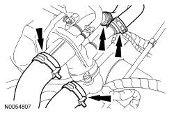
4 18. Disconnect the vacuum hose and the Evaporative Emission (EVAP) tube from the upper intake manifold. 19. Detach the vacuum tube retainer. 20. Disconnect the upper radiator hose, lower radiator hose and 2 heater hoses from the thermostat housing. 21. Disconnect the transaxle control cable from the control lever. 4/23


5 22. Remove the 3 nuts and position the transaxle control cable bracket aside. 23. If equipped, remove the bolt and position the ground wire aside. 24. If equipped, detach the engine block heater harness from the radiator support, power steering hose, A/C tube and the engine wiring harness. 25. Detach the coolant tube retainer clips from the A/C tube. 26. Remove the nut and disconnect the A/C tube from the condenser. Discard the O-ring seal. 5/23


6 27. Remove the 2 A/C tube bracket bolts. 28. Remove the A/C tube bracket bolt. 29. NOTE: Discard the O-ring seal. Remove the 2 nuts and disconnect the A/C tubes. 1. Remove the A/C low pressure tube assembly. 2. Position the A/C high pressure tube aside. 30. Detach the 2 wiring harness retainers. 6/23


7 31. Disconnect the 2 engine wiring harness electrical connectors. 32. Remove the 2 wiring harness retainers from the LH valve cover stud bolts and position the wiring harness aside. 33. Disconnect the hose from the power steering reservoir. Detach the pin-type retainer from the engine mount brace. 34. Remove the 3 bolts and position the power steering reservoir aside 7/23


.")

8 35. Remove the bolt and the ground wire from the engine mount brace. 36. Remove the 3 bolts and the engine mount brace. 37. Disconnect and remove the fuel supply tube. For additional information, refer to Section NOTE: Use a steering wheel holding device (such as Hunter or equivalent). Using a suitable holding device, hold the steering wheel in the straight-ahead position. 8/23
9 39. Remove the 2 nuts and the steering joint cover. 40. NOTICE: Do not allow the intermediate shaft to rotate while it is disconnected from the gear or damage to the clockspring can occur. If there is evidence that the intermediate shaft has rotated, the clockspring must be removed and recentered. For additional information, refer to Section B. NOTE: Index-mark the steering column shaft position to the steering gear for reference during installation. Remove the bolt and disconnect the steering column shaft from the steering gear. Discard the bolt. 41. Disconnect the PCM electrical connectors and pin-type retainers. 9/23
 and the LH splash shield. 44.")

10 42. Remove the 4 screws and position the LH fender splash shield aside. 43. Remove the 6 pin-type retainers (4 shown) and the LH splash shield. 44. NOTICE: The steering gear-to-dash seal must be removed or it will be damaged when lowering the subframe. Release the 4 clips and slide the steering gear-to-dash seal off of the steering gear and into the passenger compartment. 10/23


11 45. Disconnect the transaxle cooler hoses. 46. Remove the drain plug and drain the engine oil. Install the drain plug and tighten to 27 Nm (20 lb-ft). 47. Remove and discard the engine oil filter. 48. Remove the 6 nuts and the Y-pipe assembly. Discard the gaskets and nuts. 49. Remove the 4 oil pan-to-transaxle bolts. 50. Remove the 2 fasteners and the inspection cover. 11/23


12 51. Remove and discard the 4 torque converter nuts. All-Wheel Drive (AWD) vehicles 52. NOTE: Index-mark the driveshaft for installation. Remove and discard the 4 bolts (3 shown) and support the driveshaft with a length of mechanic's wire. All vehicles 53. Using a wax pencil, mark the relationship of the front subframe to the underbody at the mounting locations. 54. NOTE: RH shown, LH similar. Detach the harness retainer. 1. Remove the bolt and ABS sensor. 2. Remove and discard the nut. 12/23


 in length onto the Powertrain Lift. https://www.motologic.")
13 Separate the stabilizer bar link from the strut. 55. NOTICE: Do not allow the caliper a assembly to hang from the brake hose or damage to the hose can occur. NOTE: RH shown, LH similar. Remove the brake tube bracket bolt. Remove the 2 bolts and the caliper. Support the caliper using mechanic's wire. 56. Position a 2 x 6 board, 40 in (1016 mm) in length and two 2 x 6 boards, 24 in (609.6 mm) in length onto the Powertrain Lift. 13/23

14 57. NOTE: RH shown, LH similar. Position the Powertrain Lift and boards. 1. Position the long board directly under the control arms. 2. Position the short boards under the engine oil pan and transmission. 58. Install an Adjustable Grip Arm from the Powertrain Lift to the LH engine-to-transmission bolt hole. 59. NOTE: RH shown, LH similar. Remove and discard the RH and LH through bolts and nuts. 14/23


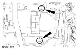
15 60. NOTE: RH shown, LH similar. Remove and discard the upper control arm nuts. 61. NOTE: RH shown, LH similar. Using the Steering Arm Remover, separate the upper ball joint from the wheel knuckle. 62. Remove the 4 engine mount nuts. Remove the 2 engine mount spacers. 63. Remove the nut, 2 bolts and the engine mount. 15/23


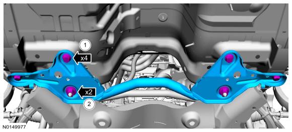
16 64. Remove the transaxle support insulator through bolt and nut. 65. Remove the transaxle support insulator bracket bolt and the 2 nuts. 66. Remove the subframe bracket. 1. Remove the 4 subframe bracket-to-body bolts. 2. Remove the 2 nuts. 67. NOTE: LH shown, RH similar. 16/23


17 Remove the 2 front subframe nuts. Lower the powertrain/subframe assembly from the vehicle. 68. Install the Engine Lift Eye on the LH cylinder head. 69. Install the Floor Crane and Spreader Bar. 70. Disconnect the wiring harness fasteners from the transaxle-to-engine stud bolt and the starter. 17/23
")


18 71. Remove the bolt and ground wire. 72. Disconnect the Transmission Control Module (TCM) electrical connector. 73. Remove the 2 nuts and the starter motor wiring. 74. Remove the 2 bolts and the starter. 75. Remove the 2 RH catalytic converter bracket bolts. 18/23
 similar.")


19 76. NOTE: Front Wheel Drive (FWD) shown, All-Wheel Drive (AWD) similar. Remove the 2 fasteners and the RH catalytic converter bracket. 77. Disconnect the RH Catalyst Monitor Sensor (CMS) electrical connector. 78. Remove the 4 nuts and the RH catalytic converter. Discard the gasket. 79. Remove the Power Steering Pressure (PSP) hose bracket bolt. 19/23
20 80. Remove and discard the PSP hose banjo bolt and the 2 seals from the steering gear. 81. Remove the Adjustable Grip Arm. 82. Install a ratchet strap from the front subframe to the LH engine lift eye. 20/23
21 83. Using the Floor Crane and Spreader Bar, remove the powertrain and subframe as an assembly from the Powertrain Lift and set on the ground. Position wood blocks under the engine and transmission. Secure the RH knuckle to the transaxle with a ratchet strap to keep RH halfshaft in place. 84. Remove the ratchet strap. 21/23


22 FWD vehicles 85. Remove the bolt and the 2 intermediate shaft bearing support stud bolts. All-Wheel Drive (AWD) vehicles 86. Remove the 2 intermediate shaft bearing support bolts. 87. Remove the 5 bolts and the Power Transfer Unit (PTU) support bracket. All vehicles 88. Remove the 2 engine-to-transaxle bolts. 89. Remove the transaxle-to-engine stud bolt and the 4 transaxle-to-engine bolts. Separate the transaxle from the engine. 22/23

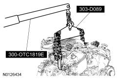
23 90. Using the Floor Crane and Spreader Bar, remove the engine. Copyright 2013 Ford Motor Company 23/23
1. With the vehicle in NEUTRAL, position it on a hoist. For additional information, refer to Section
 SECTION 303-01C: Engine 5.4L (4V) 2009 Mustang Workshop Manual REMOVAL Procedure revision date: 07/25/2008 Engine Special Tool(s) Heavy Duty Floor Crane 014-00071 or equivalent Lifting Bracket, Engine
2013 Mustang Workshop Manual
 32. Attach the wiring harness retainers to the LH side of the oil pan and the front oil pan stud bolts and install the 2 nuts. Tighten to 8 Nm (71 lb-in). 33. Position the underbody shield and install
WSS-M2C931- B. 1. With the vehicle in NEUTRAL, position it on a hoist. For additional information, refer to Section
 SECTION 303-01C: Engine 5.4L (4V) 2009 Mustang Workshop Manual IN-VEHICLE REPAIR Procedure revision date: 07/25/2008 Oil Filter Adapter Special Tool(s) Lifting Bracket, Engine (2 required) 303-D087 (D93P-6001-A1)
1999 E-Series Workshop Manual
 http://www.fordservicecontent.com/pubs/content/~wsxm/~mus~len/21/sxm31c16.h... Page 1 of 3 SECTION 303-01C: Engine 6.8L 1999 E-Series Workshop Manual IN-VEHICLE REPAIR Procedure revision date: 06/30/1998
INSTALLATION. Engine. All vehicles. 1. Install the special tool to the threaded hole located at the LH side of the engine block.
 303-01B-1 INSTALLATION Engine 303-01B-1 Special Tool(s) 3-Bar Engine Support Kit 303-F072 Lifting Brackets, Engine 303-050 (T70P-6000) Modular Engine Lift Bracket 303-F047 (014-00073) or equivalent 2.
1 of 12 10/5/2015 8:11 AM
 1 of 12 10/5/2015 8:11 AM REMOVAL 1. Perform the fuel pressure release procedure See: Fuel Pressure Release > Procedures > Fuel System Pressure Release Procedure. 2. Recover the refrigerant from the refrigerant
1998 F-150/250 Workshop Manual
 Page 1 of 13 SECTION 303-01B: Engine 4.6L and 5.4L 1998 F-150/250 Workshop Manual IN-VEHICLE REPAIR Procedure revision date: 03/07/2000 Intake Manifold Removal WARNING: Do not smoke or carry lighted tobacco
 Page 1 of 6 Section 303-01A: Basic Engine 4.2L REMOVAL 1997 F-150/250 Workshop Manual Engine Special Service Tool(s) Engine Lifting Bracket or equivalent 014-00730 Removal 1. Remove the hood. 2. On A/C
1 of 14 11/19/ :45 AM
 1 of 14 11/19/2016 11:45 AM 6F35 Digital Transmission Range (TR) Sensor Removal All vehicles 1. With the vehicle in NEUTRAL, position it on a hoist. 3.0L engine 2. Remove the Air Cleaner (ACL) outlet pipe.
Disconnect negative battery cable and remove coolant bottle cap.
 1 of 16 3/25/2012 10:18 AM ools Required SA9105E 3-Bar Engine Support Fixture SA9412G Constant Force Clamp Pliers SA9127E Gage Bar Set Powertrain Assembly Removal Caution: Do not allow smoking or the use
INSTALLATION. Engine. All vehicles. 1. Install the special tool to the threaded hole located at the LH side of the engine block.
 303-01B-1 INSTALLATION Engine 303-01B-1 Special Tool(s) 3-Bar Engine Support Kit 303-F072 Lifting Brackets, Engine 303-050 (T70P-6000) Modular Engine Lift Bracket 303-F047 (014-00073) or equivalent 2.
2014 Ford Edge SE ENGINE Fuel Tank & Lines - Edge, MKX
 17. Remove the 2 nuts, 7 bundle retainer clips and remove the fuel supply and EVAP vapor tube assembly. To install, tighten to 9 Nm (80 lb-in). 18. To install, reverse the removal procedure. FUEL LINES
2004 F-150 Workshop Manual
 Page 1 of 8 SECTION 303-01B: Engine 5.4L (3V) 2004 F-150 Workshop Manual REMOVAL Procedure revision date: 02/10/2004 Engine Printable View (943 KB) Special Tool(s) Modular Engine Lift Bracket 303-F047
2003 Escape Workshop Manual
 Page 1 of 6 SECTION 211-02: Power Steering 2003 Escape Workshop Manual REMOVAL AND INSTALLATION Procedure revision date: 04/06/2005 Steering Gear Printable View (633 KB) Special Tool(s) Tie-Rod End Remover
2012 Mustang Workshop Manual. 14. Position the lower radiator hose assembly into the vehicle. Connect the lower radiator hose to the radiator.
 14. Position the lower radiator hose assembly into the vehicle. Connect the lower radiator hose to the radiator. 15. Connect the coolant hose to the oil cooler. 16. Rotate the SC drive belt tensioner clockwise
Zoom and Print Options
 Vehicle» Engine, Cooling and Exhaust» Engine» Service and Repair» Removal and Replacement» Engine Replacement Engine Replacement ^ Tools Required - J 38185 Hose Clamp Pliers Removal Procedure 1. Remove
Engine Front Cover. Special Tool(s) Lifting Bracket, Engine (2 required) 303-D087 (D93P-6001-A1) or equivalent. Support Bar, Engine 303-F070
 Lifting Bracket, Engine (2 required) 303-D087 (D93P-6001-A1) or equivalent. Support Bar, Engine 303-F070") SECTION 303-01C: Engine 5.4L (4V) 2009 Mustang Workshop Manual IN-VEHICLE REPAIR Procedure revision date: 07/25/2008 Engine Front Cover Special Tool(s) Lifting Bracket, Engine (2 required) 303-D087 (D93P-6001-A1)
SECTION 303-01C: Engine 5.4L (4V) 2009 Mustang Workshop Manual IN-VEHICLE REPAIR Procedure revision date: 07/25/2008 Engine Front Cover Special Tool(s) Lifting Bracket, Engine (2 required) 303-D087 (D93P-6001-A1)
ENGINE ASSEMBLY. COMPONENTS (Part 1)
") 1 of 32 ENGINE ASSEMBLY COMPONENTS (Part 1) 2 of 32 COMPONENTS (Part 2) 3 of 32 COMPONENTS (Part 3) 4 of 32 COMPONENTS (Part 4) 5 of 32 COMPONENTS (Part 5) 6 of 32 COMPONENTS (Part 6) 7 of 32 COMPONENTS
1 of 32 ENGINE ASSEMBLY COMPONENTS (Part 1) 2 of 32 COMPONENTS (Part 2) 3 of 32 COMPONENTS (Part 3) 4 of 32 COMPONENTS (Part 4) 5 of 32 COMPONENTS (Part 5) 6 of 32 COMPONENTS (Part 6) 7 of 32 COMPONENTS
 Page 1 of 6 Section 07-01A: Transaxle, Automatic CD4E 1996 Probe Workshop Manual REMOVAL Procedure revision date: 06/14/2000 Transaxle Item Part Number Description 1 10655 Battery 2 10732 Battery Tray
LINCOLN. Continental 1
 3154_U01.qxd 8/1/03 7:28 AM Page 1 Continental 1 BRAKES...1-27 DRIVE TRAIN...1-21 ENGINE REPAIR...1-7 FUEL SYSTEM...1-20 PRECAUTIONS...1-7 SPECIFICATION CHARTS...1-2 STEERING AND SUSPENSION...1-22 A Air
2011 Mercury Grand Marquis LS
 Fig. 6: Locating Intake Manifold Crash Bracket With Tie Strap 24. Remove the intake manifold crash bracket bolt. 25. Disconnect the fuel rail pressure and temperature sensor vacuum and electrical connectors.
Cylinder Block Cradle
 SECTION 303-01A: Engine 4.0L SOHC 2009 Mustang Workshop Manual IN-VEHICLE REPAIR Procedure revision date: 01/27/2010 Cylinder Block Cradle Special Tool(s) Lifting Bracket, Engine 303-050 (T70P-6000) Support
2000 Econoline Workshop Manual. 3. Install the upper intake manifold. 2. NOTE: Tighten the bolts in two stages.
 2. NOTE: Tighten the bolts in two stages. Tighten the bolts in the sequence shown. Stage 1: Tighten to 2 Nm (18 lb-in). Stage 2: Tighten to 10 Nm (89 lb-in). 3. Install the upper intake manifold. Position
IN-VEHICLE REPAIR. Upper Intake Manifold
 303-01-1 Engine 3.9L and 4.2L 303-01-1 IN-VEHICLE REPAIR Upper Intake Manifold Special Tool(s) Remover, Spark Plug Wire 303-106 (T74P-6666-A) Material Item Silicone Brake Caliper Grease and Dielectric
REMOVAL AND INSTALLATION
 303-03-1 Engine Cooling 303-03-1 REMOVAL AND INSTALLATION Radiator, Cooling Fan and Shroud Special Tool(s) Wrench, Fan Clutch Nut 303-240 (T84T-6312-D) Holding Wrench, Fan Pulley 303-239 (T84T-6312-C)
M-9424-M50B 2012 Boss 302 Intake Manifold INSTALLATION INSTRUCTIONS
 !!! PLEASE READ ALL OF THE FOLLOWING INSTRUCTIONS CAREFULLY PRIOR TO INSTALLATION. WARNING: CUSTOM CALIBRATION REQUIRED! CALIBRATION NOT INCLUDED! KIT CONTENTS: 1) Intake Manifold Assembly 2) Assembly
Lower Arm. Special Tool(s) Lifting Bracket, Engine 303-D087 (D93P-6001-A1) Support Bar, Engine 303-F070
 Lifting Bracket, Engine 303-D087 (D93P-6001-A1) Support Bar, Engine 303-F070") Lower Arm Special Tool(s) Lifting Bracket, Engine 303-D087 (D93P-6001-A1) Support Bar, Engine 303-F070 Item Part Number Description 1 W710141 Lower arm rearward flag bolt (2 required) 2 W709865 Lower arm
Lower Arm Special Tool(s) Lifting Bracket, Engine 303-D087 (D93P-6001-A1) Support Bar, Engine 303-F070 Item Part Number Description 1 W710141 Lower arm rearward flag bolt (2 required) 2 W709865 Lower arm
10/20/ Ford E 250 Engine Mechanical > Engine, 4.6L and 5.4L > IN VEHICLE REPAIR > Intake Manifold 5.4L
 2005 Ford E 250 : Engine Mechanical > Engine, 4.6L and 5.4L > IN VEHICLE REPAIR > Intake Manifold 5.4L Intake Manifold 5.4L Listen SECTION 303 01A: Engine 4.6L and 5.4L 2005 E Series Workshop Manual IN
1. Remove the battery tray. For additional information, refer to Battery Tray ( )
") Page 1 of 11 Removal 1. Remove the battery tray. For additional information, refer to Battery Tray (86.15.11) 2. Remove the air cleaner. For additional information, refer to Air Cleaner (19.10.05) 3. NOTE
Page 1 of 11 Removal 1. Remove the battery tray. For additional information, refer to Battery Tray (86.15.11) 2. Remove the air cleaner. For additional information, refer to Air Cleaner (19.10.05) 3. NOTE
2002 F-150 Workshop Manual
 Page 1 of 8 SECTION 307-01B: Automatic Transmission 4R70W 2002 F-150 Workshop Manual REMOVAL Procedure revision date: 04/02/2003 Transmission Special Tool(s) Retainer, Torque Converter 307-346 (T97T-7902-A)
REMOVAL AND INSTALLATION
 303-08-1 Engine Emission Control 303-08-1 REMOVAL AND INSTALLATION Exhaust Gas Recirculation (EGR) Cooler 6.4L Diesel, Vertical Cooler Item Part Number Description 1 Fuel cooler tube 2 W701317 Power steering
2002 Explorer Sport/Sport Trac Workshop Manual
 Page 1 of 17 SECTION 303-01: Engine 4.0L Single Overhead Camshaft (SOHC) IN-VEHICLE REPAIR Procedure revision date: 07/13/2005 Cylinder Head Special Tool(s) Spark Plug Wire Remover 303-106 (T74P-6666-A)
2000 Ranger Workshop Manual
 SECTION 211-02: Power Steering 2000 Ranger Workshop Manual REMOVAL AND INSTALLATION Procedure revision date: 06/1/1999 Gear Torsion Bar Suspension Special Tool(s) Remover, Tie Rod End 211-001 (TOOL-3290-D)
IN-VEHICLE REPAIR. Cylinder Head. Special Tool(s) Timing Tool, Crankshaft TDC (T97T-6303-A) or. Special Tool(s) equivalent
 Timing Tool, Crankshaft TDC (T97T-6303-A) or. Special Tool(s) equivalent") 303-01A-1 IN-VEHICLE REPAIR Cylinder Head Special Tool(s) Torque Wrench Extension 303-575 (T97T-6256-F) or equivalent Special Tool(s) 303-01A-1 Timing Tool, Crankshaft TDC 303-573 (T97T-6303-A) or equivalent
303-01A-1 IN-VEHICLE REPAIR Cylinder Head Special Tool(s) Torque Wrench Extension 303-575 (T97T-6256-F) or equivalent Special Tool(s) 303-01A-1 Timing Tool, Crankshaft TDC 303-573 (T97T-6303-A) or equivalent
Wheel Bearing and Wheel Hub All-Wheel Drive (AWD) Vehicles
 Vehicles") Rear Suspension Wheel Bearing and Wheel Hub All-Wheel Drive (AWD) Vehicles All-Wheel Drive (AWD) Vehicles Front Wheel Drive (FWD) Vehicles Removal All vehicles NOTICE: Suspension fasteners are critical
Rear Suspension Wheel Bearing and Wheel Hub All-Wheel Drive (AWD) Vehicles All-Wheel Drive (AWD) Vehicles Front Wheel Drive (FWD) Vehicles Removal All vehicles NOTICE: Suspension fasteners are critical
DESCRIPTION AND OPERATION
 303-01B-10 Engine 3.0L 303-01B-10 DESCRIPTION AND OPERATION Upper Engine Components G72932 en 303-01B-11 Engine 3.0L 303-01B-11 DESCRIPTION AND OPERATION (Continued) Item Part Number Description 1 9H589
1999 F-150/250 Workshop Manual
 Page 1 of 8 SECTION 303-01B: Engine 4.6L and 5.4L IN-VEHICLE REPAIR Procedure revision date: 02/03/1999 Intake Manifold Lightning Removal WARNING: Do not smoke or carry lighted tobacco or open flame of
 Page 1 of 8 Section 03-01: Engine, 4.6L IN-VEHICLE SERVICE 1994 Town Car/Crown Victoria/Grand Marquis Workshop Manual Oil Pan and Oil Pump Screen Cover and Tube Town Car Removal 1. Disconnect battery ground
IN-VEHICLE REPAIR. Oil Pan Lower. Removal. 2. Disconnect the LH and RH battery ground cables. For additional information, refer to Section
 303-01C-1 IN-VEHICLE REPAIR Oil Pan Lower Special Tool(s) 3-Bar Engine Support 303-F070 Lifting Eyes 303-D030 303-01C-1 2. Disconnect the LH and RH battery ground cables. For additional information, refer
Engine Removal/lnstaIlation
 Engine Removal/lnstaIlation Removal Make sure jacks and safety stands are placed properly and hoist brackets are attached to the correct positions on the engine. Make sure the vehicle will not roll off
 Page 1 of 6 Fuel Charging and Controls - Turbocharger - 2.7L V6 - TdV6 - Turbocharger RH Removal and Installation Special Tool(s) Engine support beam 303-021 Engine lifting brackets 303-1129 Removal 1.
2001 Lincoln LS Workshop Manual
 Page 1 of 10 SECTION 303-01B: Engine 3.9L 2001 Lincoln LS Workshop Manual IN-VEHICLE REPAIR Procedure revision date: 05/16/2000 Intake Manifold Removal 1. Disconnect the battery ground cable. For additional
REMOVAL. 10. REMOVE FRONT SUSPENSION MEMBER BRACE Remove the 8 bolts and brace.
 EM64 ENGINE MECHANICAL (2JZGE) EM1S801 REMOVAL 1. REMOVE ENGINE UNDER COVER 2. DRAIN ENGINE COOLANT 3. DRAIN ENGINE OIL 4. REMOVE ENGINE COVER Remove the 4 nuts and engine cover. 5. REMOVE AIR CLEANER
Crankshaft Rear Seal with Retainer Plate
 SECTION 303-01C: Engine 5.4L (4V) 2009 Mustang Workshop Manual IN-VEHICLE REPAIR Procedure revision date: 07/25/2008 Crankshaft Rear Seal with Retainer Plate Special Tool(s) Installer, Crankshaft Rear
SECTION D Fuel Charging and Controls Turbocharger
 303-04D-i Fuel Charging and Controls Turbocharger 303-04D-i SECTION 303-04D Fuel Charging and Controls Turbocharger CONTENTS PAGE Turbocharger Body On... 303-04D-2 303-04D-2 Fuel Charging and Controls
2004 Honda ELEMENT. Submodel: Engine Type: L4 Liters: 2.4 Fuel Delivery: FI Fuel: GAS. Engine Installation. Special Tools Required
 2004 Honda ELEMENT Submodel: Engine Type: L4 Liters: 2.4 Fuel Delivery: FI Fuel: GAS Engine Installation Special Tools Required Engine hanger/adapter VSB02C000015 Engine support hanger, A & Reds AAR-T-12566
2002 Escape Workshop Manual
 SECTION 303-01A: Engine 2.0L Zetec 2002 Escape Workshop Manual IN-VEHICLE REPAIR Procedure revision date: 10/25/2004 Timing Belt Special Tool(s) Crankshaft TDC Timing Peg 303-574 (T97P-6000-A) Camshaft
Fastener Tightening Specifications Specification
 2008 G6 Applies to: 3.5L Report a problem with this article Fastener Tightening s A/C Compressor Bracket Bolt Camshaft Position Actuator Assembly Bolt 16 Y 12 lb ft Camshaft Position Actuator Magnet Bolt
Oil Pan Replacement Buick Regal
 2000 Buick Regal Oil Pan Replacement Removal Procedure Tools Required J 28467-90A Engine Support Adapters J 28467-B Universal Engine Support Fixture J 36462-A Engine Support Adapter Leg Set 1. Disconnect
FULL BORE PERFORMANCE EXHAUST MANIFOLDS F-150 ECOBOOST 3.5L
 2018-01-15 FORD F150 ECOBOOST 3.5L FULL BORE PERFORMANCE MANIFOLD SET (PART #500101X) 1 FULL BORE PERFORMANCE EXHAUST MANIFOLDS F-150 ECOBOOST 3.5L INSTALLATION INSTRUCTIONS 2011-2012 FORD F150 3.5L ECOBOOST
INTAKE MANIFOLD INSPECTION/REPLACEMENT
 ATTACHMENT III Owner Notification Program 99M01 INTAKE MANIFOLD INSPECTION/REPLACEMENT AFFECTED VEHICLES: 1997 AND 1998 CROWN VICTORIA POLICE INTERCEPTOR VEHICLES WITH 4.6L SOHC ENGINES BUILT AT THE ST.
2/18/2017 Cylinder Head Assembly Service and Repair, Removal and Replacement: Cylinder Head
 Cylinder Head http://repair.alldata.com/alldata/article/display.action?componentid=65&itypeid=401&nonstandardid=2762152&vehicleid=47645&miles=&printfriendl 1/17 RH Splash Shield Accessory Drive Belt, Thermostat
2006 Ford Pickup F350 Super Duty
 Fig. 100: Identifying Evaporator Core Housing Components Removal All vehicles 1. Remove the suction accumulator. For additional information, refer to SUCTION ACCUMULATOR. 2. Remove the RH battery. For
1 of 11 7/11/2015 6:48 AM
 1 of 11 7/11/2015 6:48 AM 43. Disconnect the A/C pressure sensor. 44. Disconnect the A/C discharge hose from the compressor and secure to the cooling fan assembly. 45. Disconnect the A/C suction hose from
Engine 3.5L 2010 Edge, MKX. SPECIFICATIONS Procedure revision date: 08/26/2013. Specification. Item Specification Fill Capacity
 2010 Edge Report a prolem with this article 303-01 Engine 3.5L 2010 Edge, MKX SPECIFICATIONS Procedure revision date: 08/26/2013 s Material Fill Capacity Motorcraft High Performance Engine RTV Silicone
 Page 1 of 5 303-01B Engine 3.0L (4V) 2004 Escape IN-VEHICLE REPAIR Procedure revision date: 05/26/2005 Engine Front Cover Material Removal Item Motocraft Metal Surface Cleaner ZC-21 Silicone Gasket and
3/19/2017 9:49 AM. Transmission Replacement. Tools Required ^ J B Cooler Quick Connect Tool ^ J Transmission Jack Adapter
 1 of 16 Transmission Replacement Tools Required ^ J 41623-B Cooler Quick Connect Tool ^ J 41160 Transmission Jack Adapter Removal Procedure 1. Remove the upper filler panel. 2. Remove the upper and lower
M-5220-MB Mustang GT Side Exhaust Kit INSTALLATION INSTRUCTIONS
 Please visit www.fordracingparts.com for the most current instruction information.!!! PLEASE READ ALL OF THE FOLLOWING INSTRUCTIONS CAREFULLY PRIOR TO INSTALLATION. AT ANY TIME YOU DO NOT UNDERSTAND THE
SECTION A: Engine 4.0L SOHC 2007 Explorer/Mountaineer/Explorer Sport Trac Workshop M. IN-VEHICLE REPAIR Procedure revision date: 11/20
 2007 Explorer Sport Trac Applies to: 4.0L SOHC Report a problem wit SECTION 303-01A: Engine 4.0L SOHC 2007 Explorer/Mountaineer/Explorer Sport Trac Workshop M IN-VEHICLE REPAIR Procedure revision date:
file://c:\program Files\tsocache\OFFICE_2780\SXN~us~en~file=SXNB2012.htm~gen~ref...
 Page 1 of 14 SECTION 211-02: Power Steering 1999 Explorer/Mountaineer Workshop Manual REMOVAL AND INSTALLATION Procedure revision date: 07/27/1998 Gear 5.0L Removal 1. Place the front wheels in the straight
PARTIAL ENGINE ASSY COMPONENTS. Clip. Radiator Grille. Clip. Front Bumper Cover. Engine Under Cover LH. N m (kgf cm, ft lbf) : Specified torque
 : Specified torque") ENGINE MECHANICAL 1417 COMPONENTS 141FP01 Radiator Grille Front Bumper Cover Engine Under Cover RH Engine Under Cover LH A79361 962 1418 ENGINE MECHANICAL Heater Outlet Water Hose 7.0 (71, 62 in. lbf)
ENGINE MECHANICAL 1417 COMPONENTS 141FP01 Radiator Grille Front Bumper Cover Engine Under Cover RH Engine Under Cover LH A79361 962 1418 ENGINE MECHANICAL Heater Outlet Water Hose 7.0 (71, 62 in. lbf)
file://c:\program Files\tsocache\OFFICE_5164\SYA~us~en~file=SYA1C003.htm~gen~re...
 Page 1 of 26 SECTION 501-12: Instrument Panel and Console 2000 Crown Victoria/Grand Marquis Workshop Manual REMOVAL AND INSTALLATION Procedure revision date: 06/21/1999 Instrument Panel Removal CAUTION:
ASSEMBLY/INSTALLATION INSTRUCTIONS
 ASSEMBLY/INSTALLATION INSTRUCTIONS AURORA 3000 & 4000 SCORPION TURBO SYSTEM NOTICE: The engine oil must be changed any time the turbocharger is removed from the engine. The passages in the block underneath
2002 Taurus/Sable Workshop Manual
 SECTION 211-02: Power Steering REMOVAL AND INSTALLATION 2002 Taurus/Sable Workshop Manual Power Steering Pump Pulley CII Pump Special Tool(s) Installer, Power Steering Pump Pulley 211-009 (T65P-3A733-C)
Valve Cover - RH Material
 1 of 5 5/15/2015 8:06 AM Valve Cover - RH Material 2 of 5 5/15/2015 8:06 AM 3 of 5 5/15/2015 8:06 AM Removal CAUTION: During engine repair procedures, cleanliness is extremely important. Any foreign material,
Lower Intake Manifold Replacement
 Lower Intake Manifold Replacement Removal Procedure 1. Turn OFF all the lamps and the accessories. 2. Ensure the ignition switch is in the OFF position. 3. Disconnect the negative battery cable from the
CERTAIN 2018 MODEL YEAR EXPEDITION AND NAVIGATOR VEHICLES EQUIPPED WITH R-1234YF REFRIGERANT - SPECIAL R-1234YF REFRIGERANT SERVICE INFORMATION
 PAGE 1 OF 33 CERTAIN 2018 MODEL YEAR EXPEDITION AND NAVIGATOR VEHICLES EQUIPPED WITH R-1234YF REFRIGERANT - SPECIAL R-1234YF REFRIGERANT SERVICE INFORMATION OVERVIEW This program provides special service
2004 Lincoln LS Workshop Manual
 SECTION 310-00: Fuel System 2004 Lincoln LS Workshop Manual REMOVAL AND INSTALLATION Procedure revision date: 01/23/2004 Fuel Tank and Filler Pipe Printable View (541 KB) Special Tool(s) Fuel Drain Hose
Water Pump Replacement (L4)
") 2011 Chevrolet Equinox Equinox, Terrain VIN L Service Manual Water Pump Replacement (L4) Special Tools EN-43651 Water Pump Holding Tool For equivalent regional tools, refer to Special Tools. Removal Procedure
2011 Chevrolet Equinox Equinox, Terrain VIN L Service Manual Water Pump Replacement (L4) Special Tools EN-43651 Water Pump Holding Tool For equivalent regional tools, refer to Special Tools. Removal Procedure
PARTIAL ENGINE ASSY (2ZZ GE)
") COMPONENTS 14189 140R701 7.0 (71, 62 in. lbf) Cylinder Head Cover No. 2 19 (194, 14) Radiator Support Upper 19 (194, 14) Radiator Hose Inlet Cruise Control Actuator Assy 6.0 (61, 53 in. lbf) Radiator Assy
COMPONENTS 14189 140R701 7.0 (71, 62 in. lbf) Cylinder Head Cover No. 2 19 (194, 14) Radiator Support Upper 19 (194, 14) Radiator Hose Inlet Cruise Control Actuator Assy 6.0 (61, 53 in. lbf) Radiator Assy
Engine Removal/Installation
 Engine Removal/Installation Make sure jacks and safety stands are placed properly and hoist brackets are attached to correct positions on the engine. (See Section 1). Apply parking brake and block rear
2010 Town Car Workshop Manual. REMOVAL AND INSTALLATION Procedure revision date: 08/20/2009
 SECTION 502-02: Full Frame and Body Mounting REMOVAL AND INSTALLATION Procedure revision date: 08/20/2009 Crossmember - Number 2 Special Tool(s) Engine Support Bar 303-F072 Support Bracket, Engine 303-639
 Page 1 of 10 43: Transmission, automatic, B5254T2, AW50/51 AWD V70 XC (01-) / XC70 (-07), 2004, B5254T2, AW50/51 AWD, L.H.D, YV1SZ59H241147306, 147306 15/10/2011 PRINT 43: Transmission, automatic, B5254T2,
2002 Crown Victoria/Grand Marquis Workshop Manual
 Page 1 of 24 SECTION 303-01: Engine 2002 Crown Victoria/Grand Marquis Workshop Manual INSTALLATION Procedure revision date: 01/02/2003 Cylinder Heads Special Tool(s) Installer, Crankshaft Vibration Damper
Coolant Pump, Remove and Install (Z 22 SE)
") Page 1 of 10 Coolant Pump, Remove and Install (Z 22 SE) Remove 1. Open the bonnet. 2. Disconnect the battery. 3. Open the rear engine cover (1). 4. Detach the rear engine cover. 6 bolts (2) and (3) 5.
Page 1 of 10 Coolant Pump, Remove and Install (Z 22 SE) Remove 1. Open the bonnet. 2. Disconnect the battery. 3. Open the rear engine cover (1). 4. Detach the rear engine cover. 6 bolts (2) and (3) 5.
7. Remove the starter motor. Refer to Starter Motor Replacement (2.2L) or Starter Motor Replacement (4.3L).
 or Starter Motor Replacement (4.3L).") 1 of 9 1/5/2013 6:40 PM Removal Procedure 1. Disconnect the battery negative cable. Refer to Battery Replacement. 2. Remove the hood. Refer to Hood Replacement. 3. If the vehicle is equipped with a manual
1 of 9 1/5/2013 6:40 PM Removal Procedure 1. Disconnect the battery negative cable. Refer to Battery Replacement. 2. Remove the hood. Refer to Hood Replacement. 3. If the vehicle is equipped with a manual
Weistec True Downpipes
 Weistec True Downpipes Installation Guide, W212, W218, AWD 2014+ E63 2014+ CLS63 WARNING! IF YOU ARE NOT EXPERIENCED IN THE AREA OF AUTOMOTIVE MECHANICS, WE STRONGLY URGE THAT YOU REFER THIS INSTALLATION
2001 Chevrolet CORVETTE
 riveline Support Assembly Replacement (Automatic Transmission) 1 of 21 10/24/2012 8:58 PM 2001 Chevrolet CORVETTE Submodel: Engine Type: V8 Liters: 5.7 Fuel Delivery: FI Fuel: GAS Driveline Support Assembly
Zoom and Print Options
 Vehicle» Powertrain Management» Fuel Delivery and Air Induction» Fuel Tank» Service and Repair» Procedures» Fuel Tank Removal and Installation REMOVAL WARNING: DO NOT SMOKE OR CARRY LIGHTED TOBACCO OR
SECTION B Engine 5.0L (4V)
") 303-01B-i Engine 5.0L (4V) 303-01B-i SECTION 303-01B Engine 5.0L (4V) CONTENTS PAGE SPECIFICATIONS... 303-01B-2 303-01B-2 Engine 5.0L (4V) 303-01B-2 SPECIFICATIONS Material Motorcraft Metal Surface Prep
303-01B-i Engine 5.0L (4V) 303-01B-i SECTION 303-01B Engine 5.0L (4V) CONTENTS PAGE SPECIFICATIONS... 303-01B-2 303-01B-2 Engine 5.0L (4V) 303-01B-2 SPECIFICATIONS Material Motorcraft Metal Surface Prep
WARNING: ALWAYS relieve fuel pressure before disconnecting any fuel related component. DO NOT allow fuel to contact engine or electrical components.
 4.0L V8 - VINS [K,U] Selected Block 1990 Lexus LS 400 For Lextreme Powertrain 2020 S. Hacienda Blvd. # D Hacienda Heights California 91745 Copyright 1998 Mitchell Repair Information Company, LLC Friday,
Intake Components 1117
 Item Part Number Description 1 W705654 Bolt 2 N807309 Bolt (2 req'd) 3 9F460 Bracket 4 N807071 Bolt (5 req'd) 5 9A448 Intake manifold (upper) 6 9E498 Vacuum harness 7 9F792 Fuel injection supply manifold
IN-VEHICLE REPAIR. Engine Front Cover
 303-01B-1 IN-VEHICLE REPAIR Engine Front Cover Material Item Specification 303-01B-1 Special Tool(s) Motorcraft SAE 5W-20 WSS-M2C930-A Premium Synthetic Blend 3-Jaw Puller Motor Oil 303-D121 XO-5W20-QSP
Intake Manifold Removal
 PLEASE READ ALL OF THE FOLLOWING INSTRUCTIONS CAREFULLY PRIOR TO INSTALLATION. AT ANY TIME YOU DO NOT UNDERSTAND THE INSTRUCTIONS Parts included: -GT350 Intake manifold M-944-M5 -GT350 Air bucket w/filter.
10 +/- 2 degrees before top dead center (BTDC)
") 1996 Ford Contour L4-122 2.0L DOHC VIN 3 SFI Ignition Timing Adjustments Base ignition timing is referenced to the position of the crankshaft position sensor. It is set at 10 +/- 2 degrees before top dead
1996 Ford Contour L4-122 2.0L DOHC VIN 3 SFI Ignition Timing Adjustments Base ignition timing is referenced to the position of the crankshaft position sensor. It is set at 10 +/- 2 degrees before top dead
SECTION A Engine Cooling
 303-03A-i Engine Cooling 303-03A-i SECTION 303-03A Engine Cooling CONTENTS PAGE DESCRIPTION AND OPERATION Engine Cooling... 303-03A-2 Coolant Flow Diagram... 303-03A-3 303-03A-2 Engine Cooling 303-03A-2
IN-VEHICLE REPAIR. Main Control Valve Body. Removal. 6. Disconnect the transaxle wiring harness electrical connector and TR sensor connector.
 307-01-1 Automatic Transaxle/Transmission 307-01-1 IN-VEHICLE REPAIR Main Control Valve Body Material Item Thread Sealant with PTFE TA-24 Motorcraft MERCON Multi-Purpose (ATF) Transmission Fluid XT-2-QDX
2000 Toyota Celica GT-S L4-1762cc 1.8L DOHC MFI - Removal and Installation
 Page 1 of 8 Removal and Installation REMOVAL 1. REMOVE HOOD Torque: 13 Nm (130 kgf-cm, 9 ft. lbs.) 2. REMOVE BATTERY 3. REMOVE ECM AND ECM CASE Torque: 6.9 Nm (70 kgf-cm, 61 inch lbs.) 4. REMOVE ECM BRACKET
IN-VEHICLE SERVICE. Engine Components
 file://c:\tso\tsocache\vdtom_5368\svk~us~en~file=svk31a14.htm~gen~ref.htm Page 1 of 10 Section 03-01A: Engine, 2.3L I-4 IN-VEHICLE SERVICE 1997 Ranger Workshop Manual Engine Components The views shown
REMOVAL AND INSTALLATION
 310-00-1 Fuel System 310-00-1 REMOVAL AND INSTALLATION Fuel Tank and Filler Pipe Special Tool(s) Fuel Tank Drain Hose 310-F013 2. NOTE: Steps 2 through 5 are only necessary if servicing the fuel tank or
M-FR3-FA Fiesta Handling Pack INSTALLATION INSTRUCTIONS
 Please visit www.fordracingparts.com for the most current instruction information!!! PLEASE READ ALL OF THE FOLLOWING INSTRUCTIONS CAREFULLY PRIOR TO INSTALLATION. AT ANY TIME YOU DO NOT UNDERSTAND THE
SECTION A Engine 3.7L
 303-01A-i Engine 3.7L 303-01A-i SECTION 303-01A Engine 3.7L CONTENTS PAGE SPECIFICATIONS... 303-01A-2 303-01A-2 Engine 3.7L 303-01A-2 SPECIFICATIONS Material Motorcraft High Performance Engine RTV Silicone
6.4L EGR Delete With Intake Elbow
 6.4L EGR Delete With Intake Elbow J I E C B F D G H A Part# A B C D E F G H I J PACKING LIST: QTY. 2 4 2 4 2 Description Exhaust Block-Off Plate Exhaust Gasket Coolant Line Plugs Brass Barbed Hose Connector
This information covers the proper procedure for replacing the Volvo D16F engine in a VT or VNL chassis.
 Volvo Trucks North America Greensboro, NC USA Engine, Replacement DService Bulletin Trucks Date Group No. Page 10.2007 210 139 1(47) Engine, Replacement Volvo D16F VNL, VT W2005773 This information covers
1 Part Number: M-2300-Y Part Description: S550 Mustang-Shelby Brake Upgrade Kit Installation Instructions
 Please visit www.performanceparts.ford.com for the most current instruction and warranty information. PLEASE READ ALL OF THE FOLLOWING INSTRUCTIONS CAREFULLY PRIOR TO INSTALLATION. AT ANY TIME YOU DO NOT
Audi > B4 > Liter V6 2V Engine Mechanical, Engine Code(s): AAH, AFC 10 Engine Assembly
: AAH, AFC 10 Engine Assembly") Audi > B4 > 1993 1995 2.8 Liter V6 2V Engine Mechanical, Engine Code(s): AAH, AFC 10 Engine Assembly Removing The engine is removed from above, after being separated from the transmission. Note: All tie
Audi > B4 > 1993 1995 2.8 Liter V6 2V Engine Mechanical, Engine Code(s): AAH, AFC 10 Engine Assembly Removing The engine is removed from above, after being separated from the transmission. Note: All tie
TRANSMISSION REMOVAL & INSTALLATION - A/T
 TRANSMISSION REMOVAL & INSTALLATION - A/T 1990 Nissan 240SX 1990 TRANSMISSION SERVICING Nissan Automatic Transmission Axxess, Maxima, Pathfinder, Pickup, Pulsar NX, Sentra, Stanza, 240SX, 300ZX NOTE: For
Torque Specifications for 2003 Hyundai Tiburon (GK) 2.7L DOHC
 2.7L DOHC") Torque Specifications for 2003 Hyundai Tiburon (GK) 2.7L DOHC Engine Mechanical System Camshaft sprocket bolt 90 ~ 110 900 ~ 1,100 65 ~ 80 Cylinder head cover bolt 8 ~ 10 80 ~ 100 5.8 ~ 7.2 Main bearing
Torque Specifications for 2003 Hyundai Tiburon (GK) 2.7L DOHC Engine Mechanical System Camshaft sprocket bolt 90 ~ 110 900 ~ 1,100 65 ~ 80 Cylinder head cover bolt 8 ~ 10 80 ~ 100 5.8 ~ 7.2 Main bearing
M-6642-MB Boss Oil Cooler INSTALLATION INSTRUCTIONS
 !!! PLEASE READ THE FOLLOWING INSTRUCTIONS CAREFULLY PRIOR TO INSTALLATION!!! Caution: If you are not confident that you can complete the installation safely, have it completed by a certified technician!
Engine and A4LDE Automatic Transmission Remove and Install ( ) Remove
 Remove") Engine and A4LDE Automatic Transmission Remove and Install ( 3 0) Special Tools 068A -068A Engine lifting bracket -540 Bolt tightening angle gauge Workshop Equipment Transmission jack Workshop crane Assembly
Engine and A4LDE Automatic Transmission Remove and Install ( 3 0) Special Tools 068A -068A Engine lifting bracket -540 Bolt tightening angle gauge Workshop Equipment Transmission jack Workshop crane Assembly