Series 40 Axial Piston Motors
|
|
|
- Dorthy Davidson
- 5 years ago
- Views:
Transcription


1 Technical Information powersolutions.danfoss.com
2 Revision history Table of revisions Date Changed Rev February 2017 Corrected document formatting 0703 October 2016 Minor updates 0702 January 2014 Danfoss layout GA September 2013 add system pressure information FG June 2013 add anti-cavitation option FF April 2011 correct system pressure gauge port 7/16-20 FE August 2010 new back page FD March 2010 minor edits FC November 2007 correction to maximum torque rating 15 and 19 tooth FB April 2007 Revised dimensions for straight keyed shaft FA September-2006 Corrections in model code examples F September-2005 Major Revision E 2 Danfoss February L
3 Contents General description Technical Specifications Operating Parameters System design parameters Product coding Features and options Shaft options Control options Installation drawings Basic design... 5 Key features... 5 Cross sections... 6 System circuit diagram...7 M46 motor schematic...7 Overview...8 General... 8 Features and options... 8 Specifications...8 Operating parameters... 8 Fluid specifications... 9 Hydraulic unit life... 9 Performance... 9 Bearing life and external shaft loading Fluids Viscosity...12 Temperature Case pressure...12 System Pressure...13 Speed ratings...13 Sizing equations Filtration Bypass valve Loop flushing valve Charge Flow Charge Pressure/Open Circuit Operation Redundant braking system requirement Reservoir...16 Overpressure protection Revised model code...18 Model code modules...18 Fixed motor...18 Variable motor Anti-Cavitation Valve Option...20 Displacement limiters...20 Speed sensor option...21 Pulse pickup and connector...23 Shaft options...23 Through-shaft options M25 MF M35/44 MF...25 M35/44 MV M46 MV...27 Direct displacement control (DDC) External Control Handle Requirements...28 Two-position hydraulic control...29 Danfoss February L
4 Contents Schematics M25 MF: axial ports, twin ports, loop flushing, speed sensor M25 MF: mounting flange M35/M44 MF: mounting flange...32 M35/M44 MF: axial ports, twin ports, loop flushing, speed sensor...33 M35/M44 MF: radial ports, twin ports, anti-cavitation valve...34 M35/M44 MF: side ports, through shaft...35 M35/M44 MV: twin ports...36 M35/M44 MV: mounting flange, trunnion control M46 MV: side ports, loop flushing...37 M46 MV: axial ports, loop flushing...39 M46 MV: side ports, thru shaft twin ports, loop flushing...40 M46 MV: mounting flange M46 MV: control ports...42 Motor Schematics Danfoss February L
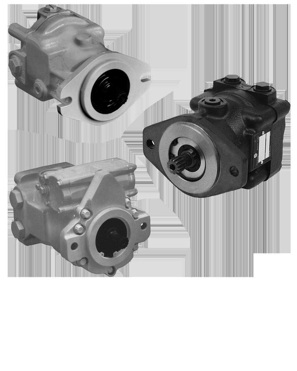
5 General description Basic design Series 40 is a family of hydrostatic pumps and motors for medium power applications with maximum loads of 345 bar [5000 psi]. These pumps and motors can be applied together or combined with other products in a system to transfer and control hydraulic power. Series 40 transmissions (pump plus motor) provide an infinitely variable speed range between zero and maximum in both forward and reverse modes of operation. The pumps and motors each come in four frame sizes: M25, M35, M44, and M46. Series 40 pumps are compact, high power density units. All models use the parallel axial piston / slipper concept in conjunction with a tiltable swashplate to vary the pump s displacement. Reversing the angle of the swashplate reverses the flow of fluid from the pump, reversing the direction of rotation of the motor output. Series 40 M35, M44, and M46 pumps may include an integral charge pump to provide system replenishing and cooling fluid flow, as well as servo control fluid flow on M46 pumps. M25 pumps are designed to receive charge flow from an auxiliary circuit or from a gear pump mounted on the auxiliary mounting pad. Series 40 pumps feature a range of auxiliary mounting pads to accept auxiliary hydraulic pumps for use in complementary hydraulic systems. Series 40 M46 pumps offer proportional controls with either manual, hydraulic, or electronic actuation. An electric three-position control is also available. The M25, M35, and M44 pumps include a trunnion style direct displacement control. Series 40 motors also use the parallel axial piston / slipper design in conjunction with a fixed or tiltable swashplate. The family includes M25, M35, M44 fixed motor units and M35, M44, M46 variable motor units. The M35 and M44 variable motors feature a trunnion style swashplate and direct displacement control. The M46 variable motors use a cradle swashplate design and a two-position hydraulic servo control. Key features 3 sizes of variable displacement motors 3 sizes of fixed displacement motors Efficient axial piston design Complete family of control systems Proven reliability and performance Compact, lightweight Worldwide sales and service Danfoss February L
6 General description Cross sections M35/M44 variable motor (MV), M25 fixed motor (MF), M35/M44 fixed motor (MF), M46 variable motor (MV) (SAE flange) Piston Cylinder block Output shaft Displacement limiter Cylinder Bearing Output shaft Bearing Lip seal Piston Swash plate Lip seal Cylinder block Piston Output shaft Piston Bearing Output shaft Bearing Lip seal Cylinder block Lip seal Swash plate Servo piston P101738E 6 Danfoss February L
7 General description System circuit diagram Control handle Heat exchanger bypass Reservoir Filter Cylinder block assembly Displacement control valve Heat exchanger Charge relief valve Bypass valve Fixed displacement motor Cylinder block assembly Input shaft Variable displacement pump Check valves w/ high pressure relief valve Charge pump Loop flushing module Suction flow Charge pressure Servo pressure High pressure Case flow Output shaft P100586E A Series 40 M35 fixed motor is shown in a hydraulic circuit with a Series 40 M46 variable pump. A loop flushing module is included on the motor. The circuit features suction filtration and heat exchanger. M46 motor schematic A M1 X2 X1 L2 B M2 L2 P The system ports (A and B) connect to the high pressure work lines. The motor receives pressurized fluid in its inlet port and discharges de-energized fluid through the outlet port. Either port can act as inlet or outlet; flow is bidirectional. System port pressure is gauged through ports M1 and M2. The motor has two case drains (L1 and L2). The motor may include loop flushing. Loop flushing provides additional cooling and filtration capacity. Danfoss February L
8 Technical Specifications Overview Specifications and operating parameters are shown below. Not all hardware options are available for all configurations. For additional information, see Operating Parameters on page 12, System design parameters on page 14, Product coding on page 18, Features and options on page 20 and Control options on page 28. General Product Line Product Type Direction of Rotation Installation Position Filtration Configuration Other System Requirements Series 40 motors In-line, axial piston, fixed and variable, positive displacement motors Clockwise (CW) and counterclockwise (CCW) Discretionary, the housing must be filled with hydraulic fluid before operation Suction or charge pressure filtration Independent braking system, circuit overpressure protection, suitable reservoir and heat exchanger Features and options Model M25 MF M35 MF M44 MF M35 MV M44 MV M46 MV Type of mounting SAE B SAE B SAE B SAE B SAE B SAE B Port connections Twin, Axial Side, Twin, Axial Side, Twin, Axial Twin Twin Side, Twin, Axial Output shaft options Splined, Tapered Splined, Tapered, Straight Key Splined, Tapered, Straight Key Splined Splined Splined, Tapered Control options DDC DDC Hyd. 2-pos. Loop flushing Option Option Option Option Option Option Displacement limiters Option Option Option Speed sensors Option Option Option - - Option Specifications Model Unit M25MF M35 MF M44 MF M35MV M44MV M46 MV Model configuration - Fixed Fixed Fixed Variable Variable Variable Type of mounting - SAE B SAE B SAE B SAE B SAE B SAE B Displacement cm 3 /rev [in 3 /rev] 25 [1.50] 35 [2.14] 44 [2.65] 35 [2.14] 44 [2.65] 46 [2.80] Weight kg [lbf] 11 [26] 11 [26] 11 [26] 21 [47] 21 [47] 23 [51] Mass moment of inertia kg m 2 [slug ft 2 ] [0.0013] [0.0024] [0.0023] [0.0024] [0.0023] [0.0037] Operating parameters Model M25 MF M35 MF M44 MF M35 MV M44 MV M46 MV Case pressure bar [psi] Maximum working 1.7 [25] Maximum 5.2 [75] Speed limits min -1 [rpm] max disp Danfoss February L
9 Technical Specifications Model M25 MF M35 MF M44 MF M35 MV M44 MV M46 MV max. disp min. disp min. disp System pressure bar [psi] Maximum working 345 [5000] 380 [5511] 345 [5000] 380 [5511] 345 [5000] 345 [5000] Maximum 385 [5584] 415 [6019] 415 [6019] 415 [6019] 415 [6019] 385 [5584] Fluid specifications Ratings and data are based on operation with premium petroleum-based hydraulic fluids reftaining oxidation, rust, and foam inhibitors. Parameter Unit Minimum reftinuous Maximum Hydraulic unit life Performance Viscosity mm /sec (cst) [SUS] 7 [47] [70-278] 1600 [7500] Temperature C [ F] -40 [-40] 82 [180] 104 [220] Cleanliness Filtration efficiency suction filtration ISO 4406 Class 18/13 or better β =75 (β ) charge filtration β =75 (β 10 10) Hydraulic unit life is the life expectancy of the hydraulic components. Hydraulic unit life is a function of speed and system pressure; however, system pressure is the dominant operating variable affecting hydraulic unit life. High pressure, which results from high load, reduces expected life. It is desirable to have a projected machine duty cycle with percentages of time at various loads and speeds. Danfoss calculates appropriate design pressure from this information. This method of selecting operating pressure is recommended whenever duty cycle information is available. All pressure limits are differential pressures and assume normal charge pressure. Series 40 motors will meet satisfactory life expectancy if applied within the parameters specified in this bulletin. For more detailed information on hydraulic unit life see BLN9884 Pressure and Speed Limits. This performance graph provides typical volumetric and overall efficiencies for Series 40 motors. These efficiencies apply for all Series 40 motors at maximum displacement. Motor performance as a function of operating speed 100 Efficiency - % Volumetric Efficiency bar [2500 psi] Volumetric Efficiency bar [5000 psi] Overall Efficiency bar [2500 psi] Overall Efficiency bar [5000 psi] Speed - % of Rated Speed P E Danfoss February L
10 Technical Specifications The performance map provides typical motor overall efficiencies at various operating parameters. These efficiencies apply for all Series 40 motors at maximum displacement. Motor performance as a function of operating speed bar psi % 85% 88% 89% System Pressure % 89% % 80% Speed - % of Rated Speed P E Bearing life and external shaft loading Bearing life is a function of speed, pressure and swashplate angle, plus any external loads. Other life factors include oil type and viscosity. In vehicle propulsion drives with no external loads, where the speed, pressure, and swashplate angle are often changing, normal bearing ß 10 (90% survival) life will exceed the hydraulic unit life. In non-propel drives, such as conveyors or fan drives, the operating speed and pressure may be nearly constant leading to a distinctive duty cycle compared to that of a propulsion drive. In propel applications, Danfoss recommends a bearing life review. Series 40 motors are designed with bearings that can accept some incidental external radial and thrust loads. However, any amount of external load will reduce the expected bearing life. The allowable radial shaft loads are a function of the load position, the load orientation, and the operating pressures of the hydraulic unit. All external shaft loads have an effect on bearing life. In motor applications where external shaft loads cannot be avoided, the impact on bearing life can be minimized by orienting the load to the 180 degree position (see Direction of external shaft load, next page). The recommended maximum radial load (R e ) is based on an external moment (M e ) and the distance (L) from the mounting flange to the load, (see table at below). The loads in the table reflect a worst case external load orientation (0 degrees), a continuously applied working pressure of 140 bar (2000 psi), 20 bar (285 psi) charge pressure, 1800 min -1 (rpm), and a bearing life (ß 10 ) of 2000 hours. Avoid thrust loads in either direction. The recommended maximum allowable radial load is calculated as: R e = M e / L If continuously applied external radial loads exceed the recommended maximum allowable, or thrust loads are known to occur, contact Danfoss for an evaluation of unit bearing life. Optional high capacity bearings are available. Tapered output shafts or clamp-type couplings are recommended for applications where radial shaft side loads are present. 10 Danfoss February L
11 Technical Specifications Shaft loading parameters R e M e L F B T Maximum radial side load Maximum external moment Distance from mounting flange to point of load Force of block (applies at center of gravity) Thrust load Recommended maximum external shaft moments M25 M35/44 M46 M e N m [lbf in] 29 [255] 25 [225] 24 [215] External shaft loads L FB Re T Direction of external shaft load 0 Re End view of shaft P E 90 Re 270 Re Axis of swashplate rotation 180 Re P E Danfoss February L
12 Operating Parameters Fluids Ratings and performance data are based on operating with premium hydraulic fluids containing oxidation, rust, and foam inhibitors. These include premium turbine oils, API CD engine oils per SAE J183, M2C33F or G automatic transmission fluids (ATF), Dexron II (ATF) meeting Allison C-3 or Caterpillar T0 2 requirements, and certain specialty agricultural tractor fluids. For more information on hydraulic fluid selection, see Danfoss publications: 520L0463, Hydraulic Fluids and Lubricants, Technical Information, and 520L465, Experience with Biodegradable Hydraulic Fluids, Technical Information. Viscosity Fluid viscosity limits Condition mm 2 /s (cst) SUS Minimum 7 47 Continuous Maximum Maintain fluid viscosity within the continuous range for maximum efficiency and bearing life. Minimum viscosity should only occur during brief occasions of maximum ambient temperature and severe duty cycle operation. Maximum viscosity should only occur at cold start: Limit speeds until the system warms up. See Danfoss publication: 520L0463, Hydraulic Fluids and Lubricants, Technical Information. Temperature Maintain fluid temperature within the limits shown in the table. Minimum temperature relates to the physical properties of the component materials. Cold oil will not affect the durability of the motor components. However, it may affect the ability of the motor to transmit power. Maximum temperature is based on material properties. Don't exceed it. Measure maximum temperature at the hottest point in the system. This is usually the case drain. Ensure fluid temperature and viscosity limits are concurrently satisfied. Temperature limits Temperature limits Minimum (intermittent, cold start) - 40 C [- 40 F] Continuous 82.2 C [180 F] Maximum C [220 F] Case pressure Maintain case pressure within the limits shown in the table. Ensure housing is kept filled with hydraulic fluid. Case pressure limits Maximum (continuous) Intermittent (cold start) 1.7 bar [25 psi] 5.2 bar [75 psi] W Warning Operating outside of case pressure limits will damage the motor. To minimize this risk, use full size inlet and case drain plumbing, and limit line lengths. 12 Danfoss February L
13 Operating Parameters System Pressure System pressure is the differential pressure between high pressure system ports. It is the dominant operating variable affecting hydraulic unit life. High system pressure, which results from high load, reduces expected life. Hydraulic unit life depends on the speed and normal operating, or weighted average, pressure that can only be determined from a duty cycle analysis. Application pressure is the high pressure relief or pressure limiter setting normally defined within the order code of the pump. This is the applied system pressure at which the driveline generates the maximum calculated pull or torque in the application. Maximum Working pressure is the highest recommended application pressure. Maximum working pressure is not intended to be a continuous pressure. Propel systems with application pressures at, or below, this pressure should yield satisfactory unit life given proper component sizing. Maximum pressure is the highest allowable application pressure under any circumstance. Application pressures above maximum working pressure will only be considered with duty cycle analysis and factory approval. Minimum low loop pressure must be maintained under all operating conditions to avoid cavitation. All pressure limits are differential pressures referenced to low loop (charge) pressure. Subtract low loop pressure from gauge readings to compute the differential. Speed ratings The table, Operating parameters on page 8, gives rated and maximum speeds for each displacement. Not all displacements operate under the same speed limits. Definitions of these speed limits appear below. Rated speed is the maximum recommended operating speed at full power condition. Operating at or below this speed should yield satisfactory product life. In vehicle propel applications, maximum motor speed during unloaded, on-road travel over level ground should not exceed this limit. Maximum speed is the highest operating speed permitted. Exceeding maximum speed reduces motor life and can cause loss of hydrostatic power and braking capacity. Never exceed the maximum speed limit under any operating conditions. W Warning Unintended vehicle or machine movement hazard The loss of hydrostatic drive line power, in any mode of operation (forward, neutral, or reverse) may cause the system to lose hydrostatic braking capacity. You must provide a braking system, redundant to the hydrostatic transmission, sufficient to stop and hold the vehicle or machine in the event of hydrostatic drive power loss. Speed limits Limit min -1 (rpm) M25 MF M35 MF M44 MF M35 MV M44 MV M46 MV Rated at max. displ Maximum at max. displ Rated at min. displ Maximum at min. displ Danfoss February L
14 System design parameters Sizing equations Use the following equations to compute output power, torque, speed, and input flow. Selecting the right motor starts with an evaluation of system requirements such as speed and torque. Select a motor that will transmit the required torque, then select a pump that will meet the flow and pressure requirements of the motor. For more information on hydrostatic drive selection, refer to Danfoss applications guideline BLN-9885, Selection of Drive Line Components. Based on SI units Based on US units V g n Input f ow Q = (l/min) 1000 η v V Input f ow Q = g n (US gal/min) 231 η v Output torque M = V g p η m 20 π (N m) Output torque M = V g p η m 2 π (lbf in) Output power P = Q p η t 600 (kw) Output power P = Q p η t 1714 (hp) Motor speed n = Q 1000 η v V g (min -1 (rpm)) Motor speed n = Q 231 η v V g (min -1 (rpm)) Variables SI units [US units] V g = Displacement per revolution cm 3 /rev [in 3 /rev] p O = Outlet pressure bar [psi] p i = Inlet pressure bar [psi] p = p O p i (system pressure) bar [psi] n = Speed min -1 (rpm) η v = Volumetric eff ciency η m = Mechanical eff ciency η t = Overall eff ciency (η v η m ) Filtration To prevent damage to the system, including premature wear, fluid entering the motor must be free of contaminants. Series 40 motors require system filtration capable of maintaining fluid cleanliness at ISO class 22/18/13 or better. Consider these factors when selecting a system filter: Cleanliness specifications Contaminant ingression rates Flow capacity Desired maintenance interval The filter may be located either on the inlet (suction filtration) or discharge (charge pressure filtration) side of the charge pump. Series 40 pumps are available with provisions for either suction or charge pressure filtration to filter the fluid entering the charge circuit (see Loop flushing valve on page 15). Typically, a filter with a beta ratio of β 10 = 1.5 to 2.0 is adequate. However, open circuit systems supplied from a common reservoir may have considerably higher requirements. Because each system is unique, only a thorough testing and evaluation program can fully validate the filtration system. For more information, see Danfoss publication 520L0467, Design Guidelines for Hydraulic Fluid Cleanliness. Bypass valve In some applications it is desirable to bypass fluid around the variable displacement pump, for example; to allow a vehicle to move short distances at low speeds without running the prime mover. This is done 14 Danfoss February L
15 System design parameters by opening a manually operated bypass valve. This valve connects both sides of the pump/motor circuit and allows the motor to turn. During normal operation, this valve must be fully closed. Bypass valves are available in Series 40 pumps. See Danfoss publication: 520L0635, Series 40 Pumps Technical Information. Bypass valves are intended for moving a machine or vehicle for very short distances at very slow speeds. They are NOT intended as tow valves. Loop flushing valve Series 40 motors may incorporate an integral loop flushing valve. Installations that require additional fluid to be removed from the main hydraulic circuit because of fluid cooling or cleanliness requirements, will benefit from loop flushing. A loop flushing valve will remove heat and contaminants from the main loop at a rate faster than otherwise possible. Contact your Danfoss representative for production availability on specific frame size motors. Series 40 loop flushing valves include a loop flushing relief valve with integral orifice. The flushing flow is a function of the pump charge relief valve, and the orifice size. Loop flushing flows of 3 to 7 l/min [0.75 to 2 US gal/min] are adequate for most applications. Contact your Danfoss representative for assistance. Flow l/min [US gal/min] W Warning Incorrect charge pressure settings may result in the inability to build required system pressure and/or inadequate loop flushing flows. Maintain correct charge pressure under all conditions. Typical loop flushing flow as a function of charge pressure [4.00] [3.00] 7.57 [2.00] 3.79 [1.00] [125] [175] [225] [275] [325] Charge pressure bar [psi] [375] P E Danfoss February L
16 System design parameters Loop flushing valve Loop flushing relief valve with orifice Loop flushing shuttle v alve P E Charge Flow Closed circuit operations require a charge pump to make up for lubrication and cooling losses, and to charge the low pressure side of the system loop. The total charge flow required is a sum of the charge flow requirements for the pump, plus the flow requirements for all motors in the system, plus any external loop flushing requirements. Ensure that adequate charge flow exists under all conditions of engine speed and motor speed and pressure. Charge Pressure/Open Circuit Operation M35 and M44 motors can be operated with zero pressure in the low side of the system loop. The case pressure must not be higher than 2 bar over the low side of the loop system pressure. With zero back pressure, the maximum allowed case pressure is 2 bar [29 psi]. Case drain lines must be plumbed accordingly to insure this 2 bar case pressure differential is not exceeded under any circumstances. Redundant braking system requirement W Warning Unintended vehicle or machine movement hazard. The loss of hydrostatic drive line power, in any mode of operation (forward, neutral, or reverse) may cause the system to lose hydrostatic braking capacity. You must provide a braking system, redundant to the hydrostatic transmission, sufficient to stop and hold the vehicle or machine in the event of hydrostatic drive power loss. Reservoir The reservoir provides clean fluid, dissipates heat, and removes entrained air from the hydraulic fluid. It allows for fluid volume changes associated with fluid expansion and cylinder differential volumes. Minimum reservoir capacity depends on the volume needed to perform these functions. Typically, a capacity of one half the charge pump flow (per minute) is satisfactory for a closed reservoir. Open circuit systems sharing a common reservoir will require greater fluid capacity. Locate the reservoir outlet (suction line) near the bottom, allowing clearance for settling foreign particles. Use a µm screen covering the outlet port. Place the reservoir inlet (return lines) below the lowest expected fluid level, as far away from the outlet as possible. Use a baffle (or baffles) between the reservoir inlet and outlet ports to reduce aeration and fluid surging. 16 Danfoss February L
17 System design parameters Overpressure protection Series 40 motors (as well as other system components) have pressure limits. Relief valves or pressure limiters should be present in the high pressure circuit to protect components from excessive pressures. C Caution High pressure relief valves are intended for transient overpressure protection and are not intended for continuous pressure control. Operation over relief valves for extended periods of time may result in severe heat build up. High flows over relief valves may result in pressure levels exceeding the nominal valve setting and potential damage to system components. Danfoss February L
18 Product coding Revised model code The model code is a modular description of a specific product and its options. To create an order code to include the specific options desired, see the Series 40 Motor Model Code Supplement 520L0636MC. Name plate Model code Model-No/Ident-No. Model Code MMV 046 C B A B A A R NN A A BLL DR A FF A CNN Serial-No A Made in USA M Model number Serial number Place of manufacture P Model code modules Fixed motor Displacement M M V S 4 6 C C D E F G T Z * * * Product Type P E C Seal group D Output shaft/through shaft configuration E Endcap configuration F Cylinder block group G Housing configuration T Special hardware features Z Special features (non-hardware) *** = None Variable motor Displacement M M V S 4 6 C C D E F G T Z * * * Product Type P E C Seal group D Output shaft/through shaft configuration E Endcap configuration F Control features G Housing configuration 18 Danfoss February L
19 Product coding T Special hardware features Z Special features (non-hardware) *** = None Danfoss February L
20 Features and options Anti-Cavitation Valve Option The M25, M35 and M44 fixed motors are available with an anti-cavitation valve option. The key application for this option is open circuit fan drives. The anti cavitation valve combines the function of a shock valve and check valve within the same cavity which is integrated into the endcap. The check valve function provides protection against cavitation that can occur upon introduction of an overrunning load or due to loss of input flow. In such case, the system delta pressure becomes negative and the check valve opens connecting the motor inlet and outlet, effectively short-circuiting the motor. The shock valve function is intended to be used for system overpressure protection events of limited duration only. It is not intended for continuous system pressure limitation. The shock valve is available with 280 bar or 345 bar setting. For this option the high pressure port needs to be defined upfront to get the correct motor rotation. Reversing the motor is not possible with this option. Flow direction Motor shaft rotation Port A Port B Special Hardware Feature Clockwise (CW) In Out NCD/NCF Counterclockwise (CCW) Out In NCE/NCG Anti-Cavitation Valve, Port A High Pressure Rotation Clockwise - M25 Fixed Motor M1 L2 Anti-Cavitation Valve, Port B High Pressure Rotation Counterclockwise M35/M44 Fixed Motor M1 L2 A Optional A Optional B B M2 L1 M2 L1 P Displacement limiters M35, M44, and M46 variable motors have minimum displacement limiters. Minimum unit displacement is obtained with the adjuster screw at its maximum extension from the end cap or displacement control piston cover. All motors are shipped with the displacement limiter set for minimum motor displacement. The M35 and M44 MV minimum displacement limiter is located in the end cap. The M46 MV minimum displacement limiter is located in the displacement control piston cavity. The length and configuration of this limiter will depend upon the control option installed in the motor. M46 MV units may have an optional mechanical maximum displacement limiter located in the displacement control piston cover. The maximum displacement limit can be adjusted by loosening the 20 Danfoss February L
21 Features and options sealing lock nut, adjusting displacement by rotating the screw with a screwdriver, then locking the adjuster by torquing the sealing lock nut. Maximum unit displacement is obtained with the adjuster screw standing at its maximum height out of the displacement control piston cover. All motors are shipped with the limiter set for maximum motor displacement. W Warning Undesirable output speed hazard. Take care adjusting displacement limiters. Too low of a minimum displacement setting can result in higher than expected output speed. Retorque the sealing locknut after every adjustment to prevent an unexpected changes and to prevent external leakage. Displacement limiter M35/M44 MV Sealing locknut Displacement limiter Swashplate P E Displacement limiter M46 MV Fixed minimum displacement limiter Adjustable maximum displacement limiter Adjustable minimum displacement limiter P E Speed sensor option Series 40 motors are available with a speed sensor option for direct measurement of motor output speed. You can use this sensor may to sense the direction and speed of motor rotation. A special magnetic speed ring is pressed onto the outside diameter of the cylinder block. A hall effect pulse pickup is located in the motor housing. The sensor accepts supply voltage and outputs a digital Danfoss February L
22 Features and options pulse signal in response to the speed of the ring. The output changes its high/low state as the north and south poles of the permanently magnetized speed ring pass by the face of the sensor. The digital signal is generated at frequencies suitable for microprocessor based controls. This sensor will operate with a supply voltage of 4.5 to 15 Vdc, and requires a current of 12 ma at 5.0 Vdc (minimum) under no load. Maximum operating current is 20 ma at 5 Vdc (maximum). Maximum operating frequency is 15 khz. Output voltage in High State (VOH) is sensor supply voltage minus 0.5 Vdc, minimum. Output voltage in Low State (VOL) is 0.5 Vdc, maximum. The sensor is available with a Packard Weather-Pack or 4-pin sealed connector. Contact your Danfoss representative for production availability on specific motor frame sizes, or for special speed sensor options. Speed sensor specifications Supply voltage Required current Maximum current Maximum frequency VOH VOL Magnetic ring Pulses/revolution Connector Vdc 12 5 Vdc (no load) 20 5Vdc 15 khz Supply Vdc Vdc 0.5 Vdc maximum M25 M35 M44 M Packard Weather-PackTM 3- pin, 4-pin Speed sensor cross section Speed sensor Magnetic ring Cylinder block P E 22 Danfoss February L
23 Features and options Pulse pickup and connector Speed sensor with directional signal Packard Weather-Pack 4 pin tower connector Red White Black Green TM A B C D Supply voltage + Speed signal Ground common Direction Mating parts kit part number K03379 (4 pin) Speed sensor without directional signal 3 pin Weather-Pack shroud Red White Black TM A B C Supply voltage + Speed signal Ground common Mating parts kit part number K20582 (3 pin) Shaft options Series 40 motors are available with a variety of splined, straight keyed, and tapered shaft ends. Nominal shaft sizes and torque ratings for some available shafts are shown in the accompanying table. Other shaft options may exist. Contact your Danfoss representative for availability. Shaft availability and torque ratings Shaft torque for tapered shafts The rated torque is based on the contact pressure between the shaft and hub surfaces with poor surface contact areas. With an increased quality of the contact areas, the contact pressure between the shaft and hub is increased and allows higher torque to be transmitted. Torque ratings assume no external radial loading. Continuous torque ratings for splined shafts are based on spline tooth wear, and assume the mating spline has a minimum hardness of R c 55 to full spline depth and coupling has good lubrication. Maximum torque ratings are based on shaft torsional strength and assume a maximum of 200,000 load reversals. N m [lbf in] M25 MF M35 MF M44 MF M35 MV M44 MV M46 MV Spline 13-tooth, 16/32 pitch Continuous 80 [750] 73 [650] 73 [650] 73 [650] 73 [650] 73 [650] Max 40 [1240] 226 [2000] 226 [2000] 226 [2000] 226 [2000] 226 [2000] Danfoss February L
24 Features and options Shaft availability and torque ratings (continued) N m [lbf in] M25 MF M35 MF M44 MF M35 MV M44 MV M46 MV Spline 15-tooth, 16/32 pitch Spline 19-tooth 16/32 pitch Continuous [1350] 153 [1350] 153 [1350] 153 [1350] 153 [1350] Max [3200] 362 [3200] 362 [3200] 362 [3200] 362 [3200] Continuous [1710] Max [4070] Tapered 1.00 inch Max 140 [1240] 497 [4400] 497 [4400] [4400] Straight keyed inch Max [2000] 226 [2000] Recommended mating splines for Series 40 splined output shafts should be in accordance with ANSI B92.1 Class 5. Danfoss external splines are modified Class 5 Fillet Root Side Fit. The external spline Major Diameter and Circular Tooth Thickness dimensions are reduced in order to assure a clearance fit with the mating spline. Through-shaft options Optional through-shafts are available on Series 40 fixed and variable displacement motors (as noted in the accompanying table). Through-shafts are provided for use in secondary (parking) braking systems. Through-shaft ends are not intended for continuous power transmission. Through-shaft availability and torque limitations Frame size Shaft spline Max. torque limit N m [lbf in] M35 MF 13T 16/32 P 328 [2900] M44 MF 13T 16/32 P 328 [2900] M46 MV(SAE) 13T 16/32 P 328 [2900] W Warning Potential loss of braking capacity. Exceeding these torque limits could cause shaft breakage. Ensure your application never exceeds maximum torque limits under any operating conditions. 24 Danfoss February L
25 Shaft options M25 MF Code Description Torque rating N m [lbf in] Drawing Max. torque rating Cont. torque rating E 13-tooth 16/32 pitch (ANSI B Class 5) 140 [1240] 80 [750] Mounting flange (ref.) Coupling must not protrude beyond this surface max. [1.312] 16.5 [0.65] Full spline 18.8 max. [0.74] dia. [0.8550] [0.8125] pitch dia. 30 pressure angle 13 teeth, 16/32 pitch fillet root side fit per ANSI B92.1 class 5 also mates with flat root side fit 7.9 [0.31] P E N Ø 25.4 mm [1.000 in] 1:8 taper 140 [1240] Mounting flange (ref.) 42.8 [1.68] 33.3 Gauge dim. [1.311] 27 [1.06] Coupling must not protrude beyond 25.4 max. [1.000] 6.30 x dia. Woodruff key [0.248x0.875] 0.25 [0.01] min. R on edges 3.81 max. [0.150] Gauge dia. [0.875] UNF-2A thd [1.500] taper per foot per SAE J [1.000] nominal shaft dia. P E D Ø 25.4 mm [1.000 in] 1:8 taper - with dust seal 140 [1240] ± [1.908 ± 0.44] [1.06] 3.8 max. [0.15] 6.30 x dia. Woodruff key [0.248 x 0.875] 0.25 [0.01] min. R. on edges Mounting flange ± 0.99 [0.53 ± 0.039] 3/4-16 UNF Thd ± 0.38 [0.361 ± 0.015] Gauge dimension Coupling must not protrude beyond this point Gauge dia. [0.875] P E M35/44 MF Code Description Torque rating Drawing Maximum torque rating N m [lbf in] Continuous torque rating N m [lbf in] A, C Splined output shaft 13 tooth 226 [2000] 13 tooth 73 [650] F (see table) 15 tooth 362 [3200] 15 tooth 153 [1350] 7.65 [0.301] Mounting flange (ref.) S U Coupling must not protrude beyond this surface V dia. W pitch dia. 30 pressure angle Y teeth, Z pitch fillet root side fit per ANSI B class no.5 also mates with flat root side fit T dia. P E Danfoss February L
26 Shaft options M35 / M44 MF splined shaft option Shaft option Shaft length S Shaft diameter T Full spline U Major dia. V Pitch dia. W No. teeth Y A [1.321] 18.8 [0.74] 16.5 [0.65] [0.8550] [0.8125] 13 16/32 - C [1.321] 18.8 [0.74] 16.5 [0.65] [0.8550] [0.8125] 13 16/32 13T F [1.321] [0.865] 18.5 [0.73] [0.9800] [0.9375] 15 16/32 - Pitch Z Thru shaft Code Description Torque rating Drawing Maximum torque rating N m [lbf in] Continuous torque rating N m [lbf in] N Ø 25.4 mm [1.000 in] 1:8 taper 497 [4400] Mounting flange (ref.) 42.8 [1.68] 33.3 gauge dim. [1.311] 27 [1.06] Coupling must not protrude beyond 25.4 max. [1.000] 6.30 x dia. Woodruff key [0.248 x 0.875] 0.25 [0.01] min. R on edges 3.81 max. [0.150] gauge dia. [0.875] UNF-2A thd. S Ø 22.2 mm [0.874 in] straight keyed 226 [2000] Coupling must not protrude beyond this surface Mounting flange (ref.) 7.65 [0.301] 38.1 [1.500] taper per foot per SAE J [1.000] nominal shaft dia [0.250] sq. key 38.1 [1.500] long 0.38 [0.015] min. R on edges 2.84 max. [0.112] P E ±0.025 [2.549] ± dia. ± 0.03 [0.874 ± 0.001] 9.4 [0.37] P E M35/44 MV Code Description Torque rating Drawing Maximum torque rating N m [lbf in] Continuous torque rating N m [lbf in] A Splined output shaft (see table) 73 [650] 226 [2000] 7.87 [0.310] U Coupling must not protrude beyond this surface S V dia. W pitch dia. 30 pressure angle Y teeth, 16/32 pitch fillet root side fit per ANSI B92.1 class no.5 also mates with flat root side fit Mounting flange (ref.) T dia. P E 26 Danfoss February L
27 Shaft options M35 / M44 MV splined shaft option Shaft option Max. coupling engagement S Shaft diameter T Full spline length U Major dia. V Pitch dia. W No. teeth Y A 33.3 [1.31] 18.8 [0.74] 16.5 [0.65] [0.855] [0.8125] 13 16/32 - Pitch Thru shaft M46 MV Code Description Torque rating Drawing Maximum torque rating N m [lbf in] Continuous torque rating N m [lbf in] A, B, Splined output shaft 13 tooth 226 [2000] 13 tooth 73 [650] E, F, (see table) 15 tooth 362 [3200] 15 tooth 153 [1350] D 19 tooth 460 [4070] 19 tooth 194 [1710] Coupling must not protrude beyond this surface S max. U Full Spline T max. dia. R V dia. W pitch dia. 30 pressure angle Y teeth, Z pitch fillet root side fit per ANSI B92.1 class no.5 also mates with flat root side fit Mounting flange (ref.) 7.47 [0.294] P E J 25.4 [1.000] tapered shaft 497 [4400] [1.440] max. Coupling must not protrude beyond this surface 6.30 x dia. woodruff key [0.248 x 0.875] 1/8 taper [1.500 per foot] per SAE standard J [1.000] nominal shaft dia. 3/4-16 Thd [0.875] gauge dia [1.062] Mounting flange (ref.) 9.17 gauge dim. [0.361] [1.481] 5.05 [0.199] P E M46 MV splined shaft option Shaft option Shaft extension R Max. coupling engagement S Shaft diameter T Fullspline length U Major dia. V Pitch dia. W A [1.297] 32 [1.26] 19.1 [0.75] 15.8 [0.62] [0.855] [0.8125] B [1.297] 32 [1.26] 19.1 [0.75] 15.8 [0.62] [0.855] [0.8125] E [1.485] 36.6 [1.44] 22.3 [0.88] [0.90] [0.980] [0.9375] F [1.485] 36.6 [1.44] 22.3 [0.88] [0.90] [0.980] [0.9375] D [1.485] 36 [1.44] 28.4 [1.114] [0.88] [1.230] [1.1875] No. teeth Y Pitch Z 13 16/ /32 13T 15 16/ /32 13T 19 16/ Thru shaft Contact Danfoss Application Engineering for specific installation drawings. Danfoss February L
28 Control options Direct displacement control (DDC) W Warning Unintended vehicle movement hazard. Internal forces may not return the swashplate to the neutral position under all operating conditions. The direct displacement control is available on either side of the M35 and M44 variable motors. It provides a simple, positive method of displacement control. Movement of the control shaft causes a proportional swashplate movement, thus varying the motor's displacement from full to minimum displacement. Neutral position is not factory set, nor is there any internal neutral return mechanism. The application must include provisions for all control linkage and neutral return functionality. External Control Handle Requirements Maximum allowable trunnion torque is 79.1 N m [700 lbf in]. Minimum torque necessary to hold the swashplate per 70 bar of differential system pressure is 11.3 N m [100 lbf in]. Maximum trunnion angle is 16 for M35 and M44. DDC on left side of M35 motor Minimum swashplate angle 16 for M35 16 for M44 P E Motor displacement vs swashplate rotation 100% Min. Motor displacement Trunnion rotation P E DDC input specifications Max. torque N m [lbf in] 79.1 [700] Min. torque to hold (per 70 bar [1000 psi] system pressure) N m [lbf in] Max. angle [100] 28 Danfoss February L
29 Control options Two-position hydraulic control Series 40 M46 variable displacement motors are equipped with a hydraulically controlled swashplate. The motor is spring biased toward maximum displacement. A hydraulic piston is used to shift the swashplate from maximum to minimum displacement. A single or two-line control can regulate the servo piston. With the standard single-line control option, hydraulic pressure is supplied to the control port (X1) to shift the motor to minimum displacement. The opposite end of the displacement control piston internally drains to the motor case. The swashplate shifts with a minimum pressure of 13.8 bar [200 psi]. The bias spring returns the motor to maximum displacement when control pressure is removed. The single-line control generally uses a customer supplied 2-position, 3-way control valve. Hydraulic pressure on the control piston must not exceed 27.6 bar [400 psi]. In applications which encounter frequent shifting on-the-go as part of the normal duty cycle, we recommend the optional two-line control. Applications with routine shifting from work range to travel range may not require the two-line control. to command minimum displacement, port control pressure to port X1 and drain port X2. To command maximum displacement, port control pressure to port X2 and drain port X1. The two-line control generally uses a customer supplied 2-position, 4-way control valve. Hydraulic pressure on the control piston must not exceed 27.6 bar (400 psi). Orifices in either (or both) the control valve supply and drain lines optimize the shift rate for either the single or two-line control. Contact your Danfoss representative for additional information. Input specifications bar [psi] Single line control Two line control Max. pressure on control 27.6 [400] 27.6 [400] Min. pressure to shift 13.8 [200] 13.8 [200] Control valve (customer supplied) M46 2-position hydraulic controls 2-position / 3 way Top 2-position / 4-way Port X2 Control pressure supply (for maximum displacement) Port X1 Control pressure supply (for minimum displacement) Single-line control Two-line control Bottom P100459E Danfoss February L
30 Installation drawings M25 MF: axial ports, twin ports, loop flushing, speed sensor Flow direction Motor shaft rotation Port A Port B Clockwise (CW) In Out Counterclockwise (CCW) Out In 30 Danfoss February L
31 Installation drawings 7/8-14* Port B (Twin) 7/8-14* Port B (Axial) [2.595] [1.050] [2.530] 7/8-14* Port A (Twin) 7/8-14* Port A (Axial) 25.4 [1.000] 3/4-16 SAE* case outlet L [5.29] 48.8 [1.92] 64.8 [2.55] [2.558] [3.999] 78.9 [3.11] [1.050] 56.9 [2.24] 7/16-20 UNF* System pressure gauge ports M1, M2 3/4-16* case outlet (alternate) L [6.41] 76.7 [3.02] 9.4 [0.37] Axial or Twin Ports Speed sensor option Packard Weather-pack 4-way connector (male) mates with Packard part no way tower (female) or Danfoss kit no. K [98.9] Loop flushing relief valve Loop flushing shuttle valve [3.72] [5.63] With Loop Flushing P100565E Danfoss February L
32 Installation drawings *All ports are SAE straight thread o-ring ports per SAE J514, unless otherwise specified. Shaft rotation is determined by viewing motor from output shaft end. Contact Danfoss Application Engineering for specific installation drawings. M25 MF: mounting flange 87.2 [3.44] [2.875] CCW CW [0.562] dia. P100566E M35/M44 MF: mounting flange Approx. center of gravity [2.620] Case drain - L1 and L2 both sides 4.06 [0.16] CW CCW dia. [0.562] [2.77] [3.435] P100569E *All ports are SAE straight thread o-ring ports per SAE J514, unless otherwise specified. Shaft rotation is determined by viewing motor from output shaft end. Contact Danfoss Application Engineering for specific installation drawings. 32 Danfoss February L
33 Installation drawings M35/M44 MF: axial ports, twin ports, loop flushing, speed sensor Flow direction Motor shaft rotation Port A Port B Clockwise In Out Counterclockwise Out In 92.1 [3.62] [7.34] [7.28] 30.5 [1.200] 84.8 [3.34] 1-1/16-12 O-ring boss Per SAE J [2.83] 44.4 [1.75] 7/8-14 O-ring boss Per SAE J514 Alternate case drain - L2 Axial Ported Endcap 40.1 [1.58] 7/8-14 O-ring boss Per SAE J514 Case drain - L [3.06] (2) Places Port B Port A 1-1/ [7.34] [6.08] 92.1 [3.63] 12.8 [0.51] 77.1 [3.04] 79.5 [3.13] 78.2 [3.08] 23.9 [0.94] (2) Places 71.9 [2.83] 7/16-20* System pressure gauge port - M2 Loop flushing valve (option) 7/16-20* System pressure gauge port - M1 Twin Ports Loop flushing shuttle valve (option) 99.1 [3.90] P100567E *All ports are SAE straight thread o-ring ports per SAE J514, unless otherwise specified. Shaft rotation is determined by viewing motor from output shaft end. Contact Danfoss Application Engineering for specific installation drawings. Danfoss February L
34 Installation drawings M35/M44 MF: radial ports, twin ports, anti-cavitation valve 77.7 (2x) [3.06] Port B 28.6 [1.13] (2x) Port A [7.37] [6.11] Ports A and B 6.63 ± [0.261 ± 0.025] Coupling must not protrude beyond this surface ± Sq. Key [0.312] [1.00] long R. 0.5 [0.02] on edges 78.1 [3.07] [0.133] Max. Ø ± 0.03 [1.124 ± 0.001] Anti-Cavitation Valve Port B 76.3 [3.00] 7/16-20 Str. Thd. O-ring boss Per SAE J514 System Pressure Gauge Port - M [2.84] 23.9 [0.94] (2x) 7/16-20 Str. Thd. O-ring boss Per SAE J514 System Pressure Gauge Port - M1 Anti-Cavitation Valve Port A [6.11] P108708E *All ports are SAE straight thread o-ring ports per SAE J514, unless otherwise specified. Shaft rotation is determined by viewing motor from output shaft end. Contact Danfoss Application Engineering for specific installation drawings. 34 Danfoss February L
35 Installation drawings M35/M44 MF: side ports, through shaft 7/8-14* Case drain - L3 Port B 77.7 [3.06] 67.3 [2.65] 89.7 [3.53] Port A Approx center of gravity 1-1/16-12* 17.8 [0.70] [7.34] [6.09] 92.1 [3.63] 12.8 [0.51] 44.5 [1.75] 71.9 [2.83] 65.9 [2.60] Side Ports [6.35] [7.28] 99.1 [3.90] 7/8-14* Case drain - L [2.63] 67.3 [2.63] [2.60] 1-1/16-12* 21.1 [0.83] Fulll spline length [8.594] [7.25] 92.1 [3.63] 12.8 [0.51] 29 [1.14] (2) Places 89.7 [3.53] [0.855] [2.000] 7/8-14* 70.5 [2.77] 71.9 [2.83] 1/2-13 Thd. 92 [23.3] min. full Thd. Case drain - L3 Aux. shaft option Approx. center of gravity 36.8 max. [1.45] Side Ports with thru shaft 6.3 [0.25] Coupling must not protrude beyond this surface [5.95] [6.35] 99.1 [3.90] Auxiliary drive spline data: [0.8125] pitch diameter 30 pressure angle 13 teeth, 16/32 pitch fillet root side fit ANSI B class no. 5 also mates with flat root side fit 7/8-14* Case drain - L2 P *All ports are SAE straight thread o-ring ports per SAE J514, unless otherwise specified. Shaft rotation is determined by viewing motor from output shaft end. Contact Danfoss Application Engineering for specific installation drawings. Danfoss February L
36 Installation drawings M35/M44 MV: twin ports 9/16-18* System pressure gauge Port M [3.63] 96.5 [3.80] 9/16-18* system pressure gauge Port M1 Displacement limiter 95 [3.74] 7.6 [0.301] [3.999] 80.5 [3.17] Port B Port A 16 max. Disp. min. Disp [2.63] 12.6 [0.50] 1-1/16-12* Case outlet 96.4 [3.80] 1-1/16-12* Port A 35 [1.38] 35 [1.38] 1-1/16-12* Port B [6.48] P100570E *All ports are SAE straight thread o-ring ports per SAE J514, unless otherwise specified. Shaft rotation is determined by viewing motor from output shaft end. Contact Danfoss Application Engineering for specific installation drawings. 36 Danfoss February L
Series 40 Axial Piston Motors. Technical Information
 Series 40 Axial Piston Motors Technical Information Revisions Revisions Table of Revisions Date Page Changed Rev. November 2007 31 correction to maximum torque rating 15 and 19 tooth FB April 2007 29 Revised
Series 40 Axial Piston Motors Technical Information
 Series 40 Axial Piston Motors Technical Information Series 40 Family of Pumps and Motors Series 40 is a family of hydrostatic pumps and motors for "medium power" applications with maximum loads of 345
Series 40 Direct Displacement Pumps
 Technical Information powersolutions.danfoss.com Revision history Table of revisions Date Changed Rev July 2017 Removed outdated images 0703 January 2017 Minor updates 0702 July 2015 Minor edits 0701 February
Series 90 Axial Piston Motors. Technical Information
 Series 90 Axial Piston Motors Technical Information HISTORY OF REVISIONS Table of Revisions Date Page Changed Rev. Fourth edition 2 520L0604 Contents GENERAL DESCRIPTION Cross section Cross section Cross
Series 90. Axial Piston Motors Technical Information
 Series 90 Axial Piston Motors Technical Information Series 90 Family of Pumps and Motors Series 90 hydrostatic pumps and motors can be applied together or combined with other products in a system to transfer
L and K Frame Variable Motors. Technical Information
 L and K Frame Variable Motors Technical Information Revisions Revisions Table of Revisions Date Page Changed Rev. April 2008 6 corrected the schematic drawings BE January 2008 17 removed displacement limiter
Series 90 Axial Piston Pumps. Technical Information
 Series 90 Axial Piston Pumps Technical Information Revisions History of Revisions Table of Revisions Date Page Changed Rev. March 2010 Various Fix O-ring dimensions in dimension drawings FE December 2009
Series 40 Direct Displacement Pumps. Technical Information
 Series 40 Direct Displacement Pumps Technical Information Revisions History of Revisions Table of Revisions Date Page Changed Rev. September 2013 5, 11 change system pressure specs FB August 2013 all Remove
P90 VARIABLE DISPLACEMENT PUMP T E C H N I C A L C A T A L O G
 P90 VARIABLE DISPLACEMENT PUMP T E C H N I C A L C A T A L O G Variable displacement pump POCLAIN HYDRAULICS Design Slider block Swashplate hold-down Servo piston Servo arm Piston Slipper Displacement
Series 40 Axial Piston Pumps. Technical Information
 Series 40 Axial Piston Pumps Technical Information Revisions History of Revisions Table of Revisions Date Page Changed Rev. October 2010 last new last page EJ February 2010 last Fix Osaka address EI June
Series 90 Axial Piston Pumps. Technical Information
 Series 90 Axial Piston Pumps Technical Information Using this manual ORGANIZATION AND HEADINGS To help you quickly find information in this manual, the material is divided into sections, topics, subtopics,
Series 42 4T Axial Piston Tandem Pumps
 Technical Information Series 42 4T Axial Piston Tandem Pumps powersolutions.danfoss.com Revision history Table of revisions Date Changed Rev June 2016 converted to new layout 0101 May 2015 Converted to
H1 Axial Piston Tandem Pumps Size 045/053
 MAKING MODERN LIVING POSSIBLE Technical Information H1 Axial Piston Tandem Pumps Size 045/053 powersolutions.danfoss.com Revision history Table of revisions Date Changed Rev November 2015 Master Model
Series 42 Axial Piston Pumps. Technical Information
 Series 42 Axial Piston Pumps Technical Information Revisions History of Revisions Table of Revisions Date Page Changed Rev. October 2009 59 Connector/Spool: 6=MS, high gain spool CC October 2009 8, 11
Series 45 Open Circuit Axial Piston Pumps. Technical Information. Displacement Piston. Swashplate. Piston. Tapered Roller Bearing
 Series 45 Open Circuit Axial Piston Pumps Technical Information Displacement Piston Piston Swashplate Tapered Roller earing Tapered Roller earing Valve Plate Cylinder lock Kit Shaft Seal General Description
Technical Information Series 45 G Frame powersolutions.danfoss.com
 MAKING MODERN LIVING POSSIBLE Technical Information Series 45 G Frame powersolutions.danfoss.com Contents Frame G Design... 4 Specifications... 5 Performance G74B... 6 Performance G9C... 7 Order code...
Series 20 Axial Piston Pumps. Technical Information
 Series 20 Axial Piston Pumps Technical Information General Description INTRODUCTION Sauer-Danfoss a world leader in hydraulic power systems has developed a family of axial piston pumps. DESCRIPTION Sauer-Danfoss
Series 42 Closed Circuit Axial Piston Pumps
 Technical Information Series 42 Closed Circuit Axial Piston Pumps www.danfoss.com Revision history Table of revisions Date Changed Rev August 2018 Minor Update 0103 December 2016 Minor Update 0102 June
L and K Frame Variable Motors
 Technical Information powersolutions.danfoss.com Revision history Table of revisions Date Changed Rev April 2018 Model code minimum angle update 0204 November 2016 Minor updates 0203 June 2015 new cartridge
Series 20 Axial Piston Pumps. Technical Information
 Series 20 Axial Piston Pumps Technical Information General Description INTRODUCTION Sauer-Danfoss a world leader in hydraulic power systems has developed a family of axial piston pumps. DESCRIPTION Sauer-Danfoss
4T Axial Piston Pumps. Technical Information
 4T Axial Piston Pumps Technical Information Using this manual ORGANIZATION AND HEADINGS To help you quickly find information in this manual, the material is divided into sections, topics, subtopics, and
Axial Piston Pumps Series 40 M46
 Technical Information Axial Piston Pumps Series 40 M46 powersolutions.danfoss.com Revision history Table of revisions Date Changed Rev March 2017 Minor updates - FNR Control options 0209 October 2016 Minor
Series 45 Axial Piston Open Circuit Pumps. Technical Information
 Series 45 Axial Piston Open Circuit Pumps Technical Information Revisions History of Revisions Table of Revisions Date Page Changed Rev. September 28 58-62 dimension changes for Frame J FJ June 28 78,
Series 45 Frame J Axial Piston Open Circuit Pumps. Technical Information
 Series 45 Frame J Axial Piston Open Circuit Pumps Technical Information Using this manual ORGANIZATION AND HEADINGS To help you quickly find information in this manual, the material is divided into sections,
P90 VARIABLE DISPLACEMENT PUMP T E C H N I C A L C A T A L O G
 P90 VARIABLE DISPLACEMENT PUMP T E C H N I C A L C A T A L O G Variable displacement pump POCLAIN HYDRAULICS Design Piston Slipper Slider block Servo piston Servo arm Displacement control Feedback linkage
PM50 VARIABLE DISPLACEMENT PUMP CLOSED LOOP CIRCUIT T E C H N I C A L C A T A L O G
 PM50 VARIABLE DISPLACEMENT PUMP CLOSED LOOP CIRCUIT T E C H N I C A L C A T A L O G PM50 - Variable displacement pump POCLAIN HYDRAULICS OVERVIEW PM50 is a variable displacement, axial piston pump, with
Series 90 Axial Piston Pumps
 MAKING MODERN LIVING POSSIBLE Series 90 Axial Piston Pumps powersolutions.danfoss.com Revision History Table of Revisions Date Changed Rev March 2014 corrections to pin assignments - page 48 FB February
H1 Axial Piston Pump Size 045/053, Single. Technical Information
 H1 Axial Piston Pump Size 045/053, Single Technical Information Revisions Revision History Table of revisions Date Page Changed Rev 30 Jul, 2009 First edition AA Feb 2010 various 14 teeth added BA Jun,
Series 90 Axial Piston Pumps. Technical Information
 Series 90 Axial Piston Pumps Technical Information Revisions History of Revisions Table of Revisions Date Page Changed Rev. July 2011 35 Typo, 45cc should be 42cc GB July 2011 all Major update GA August
H1 Axial Piston Pump Size 115/130, Single. Technical Information
 H1 Axial Piston Pump Size 115/130, Single Technical Information Revisions Revision History Table of revisions Date Page Changed Rev 30 Jul, 2009 First edition AA Jun, 2010 4-6, 12, 14, New EC directive
Series T90 Transit Mixer Drive System
 MAKING MODERN LIVING POSSIBLE Technical Information Series T90 Transit Mixer Drive System powersolutions.danfoss.com Contents Series T90 Transit Mixer Drive Transit Mixer Pump Series T90 General Description...
H1 Axial Piston Pump Size 147/165, Single. Technical Information
 H1 Axial Piston Pump Size 147/165, Single Technical Information Revisions Revision History Table of revisions Date Page Changed Rev 30 Jul, 2009 First edition AA Jul, 2010 4-6, 10, 12-13 New EC directive
MP1 Axial Piston Pumps Size 28/32, 38/45
 Technical Information MP1 Axial Piston Pumps Size 28/32, 38/45 www.danfoss.com Revision history Table of revisions Date Changed Rev May 2018 add 14 tooth shaft, minor edits 0106 March 2018 update MDC control
H1 Axial Piston Single Pumps Size 147/165
 MAKING MODERN LIVING POSSIBLE Technical Information H1 Axial Piston Single Pumps Size 147/165 powersolutions.danfoss.com Revision history Table of revisions Date Changed Rev September 2014 MDC, CCO, and
MP1 Axial Piston Pumps Size 28/32, 38/45
 Technical Information MP1 Axial Piston Pumps Size 28/32, 38/45 powersolutions.danfoss.com Revision history Table of revisions Date Changed Rev August 2016 First Edition 0101 2 Danfoss August 2016 BC00000352en-US
Series TMM Axial Piston Motor. Technical Information
 Series TMM Axial Piston Motor Technical Information General Description GENERAL DESCRIPTION These motors are designed primarily to be combined with other products in closed circuit systems to transfer
H1 Axial Piston Tandem Pumps Size 045/053/060/068
 Technical Information H1 Axial Piston Tandem Pumps Size 045/053/060/068 powersolutions.danfoss.com Revision history Table of revisions Date Changed Rev September 2017 add G6 option 0603 June 2017 minor
DDC20 Axial Piston Variable Displacement Pump
 Technical Information DDC20 Axial Piston Variable Displacement Pump powersolutions.danfoss.com Revision history Table of revisions Date Changed Rev February 2017 Change charge pump housing 0102 January
Axial Piston Pumps Series 40
 Series 40 Family of Pumps and Motors Series 40 is a family of hydrostatic pumps and motors for "medium power" applications with maximum loads of 345 bar (0 psi). These pumps and motors can be applied together
T1P Transit Mixer Axial Piston Pump Size 069/089
 Technical Information T1P Transit Mixer Axial Piston Pump Size 069/089 powersolutions.danfoss.com Revision history Table of revisions Date Changed Rev May 2016 Updated to Engineering Tomorrow design. 0201
shhark continuum PUMPS Group 1 l Technical Information
 shhark continuum PUMPS Group 1 l Technical Information 66M 88Y 55K 77C 33M 50C 100Y 66M 88Y 2 GROUP 1 shhark continuum PUMPS I TECHNICAL INFORMATION History of revisions Date Page Changed Rev. May 2016
PMV0 VARIABLE DISPLACEMENT PUMP CLOSED LOOP CIRCUIT T E C H N I C A L C A T A L O G
 PMV0 VARIABLE DISPLACEMENT PUMP CLOSED LOOP CIRCUIT T E C H N I C A L C A T A L O G PMV0 - Variable displacement pump POCLAIN HYDRAULICS OVERVIEW PMV0 is a variable displacement, axial piston pump, with
Group 1. Gear Pumps Technical Information
 Group Gear Pumps Technical Information Group Family of Gear Pumps SAUER-SUNDSTRAND High performance gear pumps are fixed displacement pumps which consist of the pump housing, drive gear, driven gear, DU
LPV Axial Piston Closed Circuit Pumps. Technical Information
 LPV Axial Piston Closed Circuit Pumps Technical Information Revisions History of Revisions Table of Revisions Date Page Changed Rev. October 2008 6 added serial number plate drawing AE April 2008 29 changes
H1T 045/053/060/068 H1 Axial Piston Tandem Pumps
 Technical Information H1T 045/053/060/068 H1 Axial Piston Tandem Pumps www.danfoss.com Revision history Table of revisions Date Changed Rev July 2018 Major revision. 0801 June 2018 Angle sensor chapters
Distribuíção, revenda emanutenção. CatálogosOnline. (11) (11)
 (11)") Distribuíção, revenda emanutenção CatálogosOnline (11)4174-3300-(11)4765-6775 www.hmc.com.br MAKING MODERN LIVING POSSIBLE Technical Information Axial Piston Pumps Series 20 powersolutions.danfoss.com
Distribuíção, revenda emanutenção CatálogosOnline (11)4174-3300-(11)4765-6775 www.hmc.com.br MAKING MODERN LIVING POSSIBLE Technical Information Axial Piston Pumps Series 20 powersolutions.danfoss.com
AXIAL PISTON PUMPS SHPV SECTIONAL VIEW
 AXIAL PISTON PUMPS SHPV SECTIONAL VIEW 2 SYSTEM CIRCUIT PUMP AND MOTOR CIRCUIT working loop (high pressure) working loop (low pressure) control fluid suction line case drain fluid Above figure shows schematically
Axial Piston Pumps LPV
 Technical Information Axial Piston Pumps LPV powersolutions.danfoss.com Revision history Table of revisions Date Changed Rev September 2017 update model code 0102 July 2015 Danfoss Layout 0100 January
H1 Axial Piston Pump Size 147/165, Single
 MAKING MODERN LIVING POSSIBLE Technical Information H1 Axial Piston Pump Size 147/165, Single powersolutions.danfoss.com Revision History Table of Revisions Date Changed Rev Mar 2014 Converted to Danfoss
AXIAL PISTON MOTORS SHMF
 SECTIONAL VIEW Purge relief valve High pressure relief valves (adjustable) Cylinder block assembly Shaft seal Output shaft Valve block Shuttle valve Swashplate 2 SYSTEM CIRCUIT PUMP AND MOTOR CIRCUIT working
H1 Bent Axis Variable Displacement Motors Frame Size 080 Frame Size 110. Technical Information
 H1 Bent Axis Variable Displacement Motors Frame Size 080 Frame Size 110 Technical Information Revisions History of Revisions Table of revisions Date Page Changed Rev. 1 Dec, 2008 Different pages New frame
Transit Mixer Axial Piston Motor Size 070/084/089
 Technical Information Transit Mixer Axial Piston Motor Size 070/084/089 powersolutions.danfoss.com Revision history Table of revisions Date Changed Rev June 2017 Update to Engineering Tomorrow 0202 Mar
LDU20 Closed Circuit Axial Piston Transmission
 Technical Information LDU20 Closed Circuit Axial Piston Transmission powersolutions.danfoss.com Revision history Table of revisions Date Changed Rev April 2018 minor change 0102 June 2016 Converted to
Medium Duty Piston Pump Variable Displacement Closed Circuit
 Medium Duty Piston Pump Variable Displacement Closed Circuit Model 70160 Model 70360 Model 72400 20.3 cm 3 /r [1.24 in 3 /r] 40.6 cm 3 /r [2.48 in 3 /r] 40.6 cm 3 /r [2.48 in 3 /r] 23.6 cm 3 /r [1.44 in
Series 20 Axial Piston Motors. Technical Information
 Series 20 xial Piston Motors Technical Information General Description INTRODUCTION Sauer-Danfoss a world leader in hydraulic power systems has developed a family of axial piston motors. DESCRIPTION Sauer-Danfoss
Series 2 Variable Displacement Piston Pump
 Series 2 Variable Displacement Piston Pump ACL 64-105cm 3 /r (3.9-6.4in 3 /r) 2 eaton Series 2 Variable Displacement Piston Pump E-PUPI-MC004-E1 January 2010 Series 2 Variable Displacement Piston Pump
TPV Variable Displacement Closed Loop System Axial Piston Pump THE PRODUCTION LINE OF HANSA-TMP HT 16 / M / 851 / 0813 / E
 HYDRAULIC COMPONENTS HYDROSTATIC TRANSMISSIONS GEARBOXES - ACCESSORIES THE PRODUCTION LINE OF HANSA-TMP Variable Displacement Closed Loop System CONTENTS General Information... Order Code... Manual Control
Catalog HY /NA. Catalog HY /NA. Parker Hannifin Corporation Hydraulic Pump Division Marysville, Ohio USA
 Catalog HY28-6/NA PV, PVT Series Piston Pumps Variable Volume Catalog HY28-6/NA 1 Catalog HY28-6/NA Notes Series PV 2 Catalog HY28-6/NA Introduction Series PV Quick Reference Data Chart Pump Delivery Approx.
Vickers. Vane Pumps. Double Thru-drive Vane Pumps. High speed, high pressure VQT Series for mobile equipment. Released 7/93
 Vickers Vane Pumps Double Thru-drive Vane Pumps High speed, high pressure VQT Series for mobile equipment Released 7/93 612 Introduction Double VQT high performance pumps are fixed displacement units that
H1 Axial Piston Single Pumps Size 147/165
 Technical Information H1 Axial Piston Single Pumps Size 147/165 powersolutions.danfoss.com Revision history Table of revisions Date Changed Rev May 2017 NFPE gen. 3 changes. 0701 November 2015 Master Model
Bent Axis Motors Series 51 and 51-1
 Bent Axis Motors Series 51 and 51-1 powersolutions.danfoss.com Revision history Table of revisions Date Changed Rev March 2016 minor edit 0202 June 2014 Danfoss layout BA November 2009 correction to defeated
GEAR MOTORS D Series Gear Motors including Fan Drive l Technical Information
 GEAR MOTORS D Series Gear Motors including Fan Drive l Technical Information 2 D SERIES GEAR MOTORS I TECHNICAL INFORMATION History of revisions Date Page Changed Rev. Feb. 2009 - First edition AA Nov.
H1 Axial Piston Pumps Single and Tandem
 Basic Information H1 Axial Piston Pumps Single and Tandem powersolutions.danfoss.com Revision history Table of revisions Date Changed Rev April 2017 NFPE and AC controls added. 0602 May 2016 Updated to
Series 45 Axial Piston Open Circuit Pumps Technical Information Frame F
 Design cross section LS contro l (attached to endcap) LS spoo l LS adjustmen t PC spoo l PC adjustmen t Servo piston Bias sprin g Piston Slipper Tapered roller bearing Valve plate Shaft seal Cylinder block
Bent Axis Variable Displ. Motors Series 51 and 51-1
 Technical Information ent xis Variable Displ. Motors Series 51 and 51-1 powersolutions.danfoss.com Revision history Table of revisions Date Changed Rev October 2017 Modified theor. corner power ratings
Disc Valve Hydraulic Motors 2000 Series
 Disc Valve Hydraulic Motors 10.2014 inspired hydraulics. Änderungen und Druckfehler vorbehalten 10.2014 EN EATON_Motoren english Highlights Port A Features Three zone design for longer life and true bi-directionality.
D1 High Power Open Circuit Pumps Size 130/145/193/260
 Technical Information D1 High Power Open Circuit Pumps Size 130/145/193/260 Available only for APAC / EU regions powersolutions.danfoss.com Revision history Table of revisions Date Changed Rev January
Vane Pumps. VMQ Series Vane Pumps For Industrial and Mobile Applications Displacements to 215 cm 3/ r (13.12 in 3 /r) Pressures to 260 bar (3800 psi)
 Pressures to 260 bar (3800 psi)") Vickers Vane Pumps VMQ Series Vane Pumps For Industrial and Mobile Applications Displacements to 215 cm 3/ r (13.12 in 3 /r) Pressures to 260 bar (3800 psi) 5008.00/EN/0596/A A.25 Introduction From the
Vickers Vane Pumps VMQ Series Vane Pumps For Industrial and Mobile Applications Displacements to 215 cm 3/ r (13.12 in 3 /r) Pressures to 260 bar (3800 psi) 5008.00/EN/0596/A A.25 Introduction From the
H1 Axial Piston Single Pumps Size 045/053
 MAKING MODERN LIVING POSSIBLE Technical Information H1 Axial Piston Single Pumps Size 045/053 powersolutions.danfoss.com Revision history Table of revisions Date Changed Rev August 2015 Master model code
H1 Axial Piston Single Pumps Size 045/053
 Technical Information H1 Axial Piston Single Pumps Size 045/053 www.danfoss.com Revision history Table of revisions Date Changed Rev May 2018 Major revision. 1101 May 2017 NFPE gen. 3 changes. 1001 November
Series 20 Axial Piston Motors. Technical Information
 Series 20 xial Piston Motors Technical Information General Description INTRODUCTION Sauer-Danfoss a world leader in hydraulic power systems has developed a family of axial piston motors. DESCRIPTION Sauer-Danfoss
H1B 060/080/110/160/210/250 H1 Bent Axis Motors
 H1B 060/080/110/160/210/250 H1 Bent Axis Motors www.danfoss.com Revision history Table of revisions Date Changed Rev August 2018 update adjustment chapter 0504 April 2018 Major layout update, QF080 to
Closed Circuit Axial Piston Pumps H1 45/53/60/68 Tandem
 Service Manual Closed Circuit Axial Piston Pumps H1 45/53/60/68 Tandem www.danfoss.com Revision history Table of revisions Date Changed Rev June 2018 add angle sensor topics 0303 August 2017 minor edits
H1 Axial Piston Single Pumps Size 089/100
 MAKING MODERN LIVING POSSIBLE Technical Information H1 Axial Piston Single Pumps Size 089/100 powersolutions.danfoss.com Revision history Table of revisions Date Changed Rev September 2014 MDC, CCO, and
Gear Motors Group 1, 2 and 3. Technical Information. OpenCircuitGear MEMBER OF THE SAUER-DANFOSS GROUP
 Gear Motors Group 1, 2 and 3 OpenCircuitGear Technical Information Gear Motors Group 1, 2 and 3 General Information Overview The Turolla OCG Gear Motors is a range of peak performance fixed displacement
D Series Gear Motors Including Fan Drive. Technical Information
 D Series Gear Motors Including Fan Drive Technical Information Revisions History of Revisions Table of Revisions Date Page Changed Rev. February 09 - First edition AA 09 Sauer-Danfoss. All rights reserved.
H1 Axial Piston Single Pumps Size 147/165
 H1 Axial Piston Single Pumps Size 147/165 www.danfoss.com Revision history Table of revisions Date Changed Rev September 2018 MMC update for M option added. 0802 May 2018 Angle sensor for EDC; FDC note
Disc Valve Hydraulic Motors Series 4000
 Disc Valve Hydraulic Motors Series 0 10.20 inspired hydraulics. Änderungen und Druckfehler vorbehalten 10.20 EN EATON_Motoren english Highlights Features 10 displacements, a variety of mounting flanges
AXIAL PISTON PUMPS SHPV SECTIONAL VIEW
 AXIAL PISTON PUMPS SHPV SECTIONAL VIEW 2 AXIAL PISTON PUMPS SHPV SYSTEM CIRCUIT PUMP AND MOTOR CIRCUIT working loop (high pressure) working loop (low pressure) control fluid suction line case drain fluid
VIS (Valve-In-Star) Hydraulic Motor
 Hydraulic Motor") VIS (Valve-In-Star) Hydraulic Motor VIS 30 Series VIS 40 Series VIS 45 Series The next step in the evolution of low speed high torque (LSHT) hydraulic motors. EATON Low Speed High Torque Motors E-MOLO-MC001-E5
VIS (Valve-In-Star) Hydraulic Motor VIS 30 Series VIS 40 Series VIS 45 Series The next step in the evolution of low speed high torque (LSHT) hydraulic motors. EATON Low Speed High Torque Motors E-MOLO-MC001-E5
Series 45 Axial Piston Open Circuit Pumps Technical Information
 Design Frame E cross section LS control (attached to endcap) LS spool PC spool LS adjustment PC adjustment Adjustable displacement limiter Lifting lug Displacement piston guide Displacement piston Slipper
Section 5: Hydraulic Pump SAUER DANFOSS. SERVICE MANUAL Property of American Airlines. 5-5 Page 1 September 09 HYDRAULIC PUMP
 Section 5: Hydraulic Pump SAUER DANFOSS SERVICE MANUAL HYDRAULIC PUMP 5-5 Page 1 September 09 THIS PAGE INTENTIONALLY LEFT BLANK Series 45 Frame G and H Open Circuit Axial Piston Pumps Service Manual Introduction
Series PVP Variable Volume Piston Pumps
 Series PVP Variable Volume Piston Pumps Catalog HY28-2661-CD/US zp2 hpm12-1.p65, lw, jk 1 Notes Series PVP hpm12-1.p65, lw, jk 2 Introduction Series PVP Series Sizes 6-14 Phased Out For Reference Only
GEAR PUMPS Group 3 l Technical Information
 GEAR PUMPS Group 3 l Technical Information 2 GROUP 3 GEAR PUMPS I TECHNICAL INFORMATION History of revisions Date Page Changed Rev. 28, June 2010 - First edition A 24, Feb 2011 1,2,11,32 Covers to blue
CAST IRON GEAR PUMPS AND MOTORS Cascade Group 3 l Technical Information
 CAST IRON GEAR PUMPS AND MOTORS Cascade Group 3 l Technical Information 2 CASCADE GROUP 3 I TECHNICAL INFORMATION History of revisions Date Page Changed Rev. March 2015 - First edition - September 2016
Vickers. Piston Motors. Inline Piston Motors. Fixed and Variable Displacement. Revised 5/99 691
 Vickers Piston Motors Inline Piston Motors Fixed and Variable Displacement Revised 5/99 691 Table of Contents Introduction........................................................................................
Gear Motors Group 1, 2 and 3. Technical Information. OpenCircuitGear MEMBER OF THE SAUER-DANFOSS GROUP
 Gear Motors Group 1, 2 and 3 OpenCircuitGear Technical Information Gear Motors Group 1, 2 and 3 General Information Overview The Turolla OCG Gear Motors is a range of peak performance fixed displacement
TPV Variable Displacement Closed Loop System Axial Piston Pump THE PRODUCTION LINE OF HANSA-TMP HT 16 / M / 852 / 0815 / E
 HYDRAULIC COMPONENTS HYDROSTATIC TRANSMISSIONS GEARBOXES - ACCESSORIES Certified Company ISO 9001-14001 ISO 9001 Via M. L. King, 6-41122 MODENA (ITALY) Tel: +39 059 415 711 Fax: +39 059 415 729 / 059 415
Axial Piston Pumps H1-069/078, 089/100, 115/130, 147/165, 210/250
 Service Manual Axial Piston Pumps H1-069/078, 089/100, 115/130, 147/165, 210/250 www.danfoss.com Revision history Table of revisions Date Changed Rev May 2018 add angle sensor 0308 January 20187 add seal
Eaton Fixed Displacement HHD Motor and Variable ACA Pump
 Eaton Fixed Displacement HHD Motor and Variable ACA Pump www.hydpump.com Pump Eaton 3923 4623 5423 6423 7620 7640 Motor Eaton 3933 4633 5433 6433 7630 Eaton ACA Pump Technical Data Table of values (theoretical
Group 3 Gear Pumps. Technical Information. OpenCircuitGear MEMBER OF THE SAUER-DANFOSS GROUP
 Group 3 Gear Pumps OpenCircuitGear Technical Information General Information History of revisions Table of revisions Date Page Changed Rev. 28, June 21 - First edition A 24, Feb 211 1,2,11, 32 Covers to
Open Circuit Axial Piston Pumps Series 45 Frame K2
 Open Circuit Axial Piston Pumps Series 45 Frame K2 powersolutions.danfoss.com Revision history Table of revisions Date Changed Rev April 2017 First edition 0101 2 Danfoss April 2017 AX00000301en-US0101
Disc Valve Hydraulic Motors 4000 Compact Series
 Disc Valve Hydraulic Motors 10.2014 inspired hydraulics. Änderungen und Druckfehler vorbehalten 10.2014 EN EATON_Motoren english Port B Port A Features Shuttle Valve with Back- Pressure Relief Valve Highlights
H1 Bent Axis Motors Size 060/080/110/160/210/250
 Technical Information H1 Bent Axis Motors Size 060/080/110/160/210/250 powersolutions.danfoss.com Revision history Table of revisions Date Changed Rev March 2018 Model code and ports update. 1108 February
AXIAL PISTON PUMPS AND MOTORS
 HPV-HMF SERIES SECTIONA VIEW AXIA PISTON VARIABE DISPACEMENT PUMP AXIA PISTON FIXED DISPACEMENT MOTOR Purge relief valve High pressure relief valves (adjustable) Cylinder block assembly Shaft seal Output
PM45 VARIABLE DISPLACEMENT PUMP CLOSED LOOP CIRCUIT T E C H N I C A L C A T A L O G
 PM45 VRILE DISPLCEMENT PUMP CLOSED LOOP CIRCUIT T E C H N I C L C T L O G PM45 - Variable displacement pump POCLIN HYDRULICS OVERVIEW PM45 is a variable displacement, axial piston pump, with swashplate
Hydraulic Motor/Pump. Series F11/F12 Fixed Displacement. parker.com/pmde
 Hydraulic Motor/Pump Series F11/F12 Fixed Displacement parker.com/pmde Series F11/F12 Torque (M) M = D x p x η hm 63 [Nm] Conversion factors 1 kg... 2.20 lb 1 N... 0.225 lbf 1 Nm... 0.738 lbf ft 1 bar...14.5
Closed Circuit Axial Piston Pumps H1-045/053/060/068
 Service Manual Closed Circuit Axial Piston Pumps H1-045/053/060/068 www.danfoss.com Revision history Table of revisions Date Changed Rev April 2018 add EDC with angle sensor 0303 September 2014 add MDC
Super Charged Piston Pumps Variable Displacement For Open Circuits. PAVC Medium Pressure
 aerospace climate control electromechanical filtration fluid & gas handling hydraulics pneumatics process control sealing & shielding PAVC Medium Pressure Super Charged Piston Pumps Variable Displacement
Hydraulic Motor/Pump. Series F11/F12 Fixed Displacement. parker.com/pmde
 Hydraulic Motor/Pump Series F11/F12 Fixed Displacement parker.com/pmde Series F11/F12 Torque (M) M = D x p x η hm 63 [Nm] Conversion factors 1 kg... 2.20 lb 1 N... 0.225 lbf 1 Nm... 0.738 lbf ft 1 bar...14.5