Series 90 Axial Piston Pumps. Technical Information
|
|
|
- April Melissa Webb
- 6 years ago
- Views:
Transcription


1 Series 90 Axial Piston Pumps Technical Information
2 Revisions History of Revisions Table of Revisions Date Page Changed Rev. July Typo, 45cc should be 42cc GB July 2011 all Major update GA August 2010 last new back page FF March 2010 Various Fix O-ring dimensions in dimension drawings FE December 2009 Various 42cc not available in North America FD August frame size case drain port changed to 1 5/16-12 FC July 2007 Various Minor edits and dimension changes FB March Revision F F 2011 Sauer-Danfoss. All rights reserved. Sauer-Danfoss accepts no responsibility for possible errors in catalogs, brochures and other printed material. Sauer -Danfoss reserves the right to alter its products without prior notice. This also applies to products already ordered, provided that such alterations can be made without affecting agreed specifications. All trademarks in this material are properties of their respective owners. Sauer-Danfoss, the Sauer-Danfoss logotype, the Sauer-Danfoss S-icon, PLUS+1, What really matters is inside and Know-How in Motion are trademarks of the Sauer-Danfoss Group L0603 Rev GB July 2011
3 Contents General Description Series 90 Family of Pumps and Motors... 5 PLUS+1 Compliant Controls and Sensors... 5 Design... 6 Pictorial Circuit Diagram... 7 System schematic... 7 Technical Specifications General Specifications... 8 Features and Options... 8 Operating Parameters... 9 Fluid Specifications... 9 Operating Parameters Overview...10 Input Speed...10 Independant Braking System...10 System Pressure...10 Servo Pressure...11 Charge Pressure...11 Case Pressure...12 External Shaft Seal Pressure...12 Temperature and Viscosity...12 System Design Parameters Filtration System...13 Filtration Options...14 Suction filtration Option S...14 Fluid Selection...15 Reservoir...15 Case Drain...15 Pump Life...16 Charge Pump...16 Bearing Loads and Life...17 Understanding and Minimizing System Noise...18 Sizing Equations...18 Mounting Flange Loads...19 Master Model Code Series 90 Master Model Code...21 Control Options 3-Position (FNR) Electric Control - DC, DD...25 Electric Displacement Control (EDC), Options KA, KP, KT...26 Manual Over Ride (MOR)...29 Hydraulic Displacement Control (HDC), Option HF...30 Manual Displacement Control (MDC), Options MA, MB...32 MDC with Neutral Start Switch (NSS)...33 Non Feedback Proportional Electric Control (NFPE) L0603 Rev GB July
4 Contents Features and Options Multi-Function Valves...36 Overpressure protection...36 Pressure limiting function...36 Bypass Function...37 Auxiliary Mounting Pads...38 Mating pump requirements...38 Displacement Limiter...39 Shaft Torque...40 Shaft Availability and Torque Ratings...40 Shaft Availability and Torque Ratings...41 Charge Pump...42 Charge pump sizing/selection...42 Speed Sensor...44 Connector Pin Assignments...45 Installation Drawings Frame Size Frame Size Frame Size Frame Size 075 NFPE...57 Options FK, FL, FM, FN...57 Frame Size Frame Size Frame Size Frame Size Cover Plate Position (F-N-R) Electric Control...79 Electric Displacement Control (EDC) with MS-Connector or Packard connector...80 Hydraulic Displacement Control (HDC)...80 Manual Displacement Control (MDC) with neutral start switch...81 Electrohydraulic Displacement Control (NFPE) (except 075 NFPE)...82 Integral Pressure Filter...83 Remote pressure without filter L0603 Rev GB July 2011
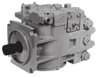
5 General Description Series 90 Family of Pumps and Motors Series 90 hydrostatic pumps and motors can be applied together or combined with other products in a system to transfer and control hydraulic power. They are intended for closed circuit applications. Series 90 advanced technology Seven sizes of variable displacement pumps Proven reliability and performance Compact, lightweight Worldwide sales and service PLUS+1 compliant controls and sensors Series 90 variable displacement pumps are compact, high power density units. All models utilize the parallel axial piston/slipper concept in conjunction with a tiltable swashplate to vary the pump s displacement. Reversing the angle of the swashplate reverses the flow of oil from the pump and thus reverses the direction of rotation of the motor output. Series 90 pumps include an integral charge pump to provide system replenishing and cooling oil flow, as well as control fluid flow. They also feature a range of auxiliary mounting pads to accept auxiliary hydraulic pumps for use in complementary hydraulic systems. A complete family of control options is available to suit a variety of control systems (mechanical, hydraulic, electric). Series 90 motors also use the parallel axial piston/slipper design in conjunction with a fixed or tiltable swashplate. They can intake/discharge fluid through either port; they are bidirectional. They also include an optional loop flushing feature that provides additional cooling and cleaning of fluid in the working loop. For more information on Series 90 motors, refer to Series 90 Motors 520L0604. PLUS+1 Compliant Controls and Sensors A wide range of Series 90 controls and sensors are PLUS+1 compliant. PLUS+1 compliance means our controls and sensors are directly compatible with the PLUS+1 machine control architecture. Adding Series 90 pumps to your application using PLUS+1 GUIDE software is as easy as drag-and-drop. Software development that used to take months can now be done in just a few hours. For more information on PLUS+1 GUIDE, visit Series 90 pumps can be used together in combination with other Sauer-Danfoss pumps and motors in the overall hydraulic system. Sauer-Danfoss hydrostatic products are designed with many different displacement, pressure and load-life capabilities. Go to the Sauer-Danfoss website or applicable product catalog to choose the components that are right for your complete closed circuit hydraulic system. 520L0603 Rev GB July
6 General Description Design Series 90 pump cross-section Slider block Servo piston Servo arm Piston Slipper Displacement control Feedback linkage Cradle bearing Bushing Cylinder block Roller bearing Valve plate Shaft seal Rear bushing Input shaft Charge pump Swashplate Cradle guide P E Typical name plate Model Code Model-No./Ident-No. Model Code Serial-No. 90L055 KA 1 N 6 S 3 C6 C 03 NNN A Model Number Serial Number Made in USA P E Place of Manufacture Series 90 pumps are also manufactured in Europe and China. Place of manufacture shown on nameplate will correspond with the actual place of manufacture L0603 Rev GB July 2011
7 General Description Pictorial Circuit Diagram This configuration shows a hydrostatic transmission using a Series 90 axial piston variable displacement pump and a Series 90 fixed displacement motor. Control handle Displacement control valve Heat exchanger bypass valve Orificed check valve Reservoir Vacuum gauge Heat exchanger Charge pressure relief valve Purge relief valve P Reversible variable displacement pump Servo control cylinder Multi-function valve Fixed displacement motor Servo pressure relief valves To pump case Charge pump Input shaft Multi-function valve Motor swashplate Output shaft Pump swashplate Servo control cylinder Loop flushing valve Pump Motor Working loop (high pressure) Working loop (low pressure) Suction line Control fluid Case drain fluid System schematic M3 A A L2 M3 M1 M1 M4 M5 M M2 B B S L2 L1 M2 P E 520L0603 Rev GB July
8 Technical Specifications General Specifications Design Direction of rotation Pipe connections Recommended installation position Auxiliary cavity pressure Axial piston pump of cradle swashplate design with variable displacement Clockwise, counterclockwise Main pressure ports: ISO split flange boss Remaining ports: SAE straight thread O-ring boss Pump installation position is discretionary, however the recommended control position is on the top or at the side, with the top position preferred. Vertical input shaft installation is acceptable. If input shaft is at the top 1 bar case pressure must be maintained during operation. The housing must always be filled with hydraulic fluid. Recommended mounting for a multiple pump stack is to arrange the highest power flow towards the input source. Consult Sauer-Danfoss for nonconformance to these guidelines. Will be inlet pressure with internal charge pump. For reference see operating parameter on next page. Will be case pressure with external charge supply. Please verify mating pump shaft seal capability. Features and Options Feature Displacement Flow at rated speed (theoretical) Torque at maximum displacement (theoretical) Mass moment of inertia of Unit cm³/rev. [in³]/rev. l/min. [US gal/min.] N m/bar [lbf in/1000 psi] kg m² Frame [2.56] 176 [46] 0.67 [410] [3.35] 215 [57] 0.88 [530] [4.59] 270 [71] 1.19 [730] [6.10] 330 [87] 1.59 [970] [7.93] 403 [106] 2.07 [1260] [10.98] 468 [124] 2.87 [1750] [15.25] 575 [160] 3.97 [2433] rotating components [slug ft²] [0.0017] [0.0044] [0.0071] [0.0111] [0.0170] [0.0280] [0.0479] Weight (with control opt. MA) kg [lb] 34 [75] 40 [88] 49 [108] 68 [150] 88 [195] 136 [300] 154 [340] Mounting (per ISO ) Flange Flange Flange Flange (SAE B) (SAE C) (SAE D) (SAE E) Rotation Right hand or Left hand rotation Main ports: 4-bolt split-flange mm (per SAE J518 code 62) [in] [0.75] [1.0] [1.0] [1.0] [1.25] [1.25] [1.5] Main port configuration Twin port Twin or side port Twin port Case drain ports (SAE O-ring boss) UNF thread (in.) Other ports SAE O-ring boss Shafts Splined, and tapered shafts available Auxiliary mounting SAE-A, B, C SAE-A, B, C, D SAE-A, B, C, D, E 8 520L0603 Rev GB July 2011
9 Technical Specifications Operating Parameters Frame Parameter Unit Input speed Minimum Rated Speed min -1 (rpm) Maximum Operating parameters Maximum working pressure 450 [6525] Maximum pressure 480 [6960] System pressure bar [psi] Maximum low loop 45 [650] Minimum low loop pressure 10 [145] Minimum 18 [261] Charge pressure bar [psi] Maximum 34 [493] Minimum (at corner power for EDC and 14 [203] FNR) Control pressure bar [psi] Minimum (at corner power for NFPE) 22 [319] Maximum 40 [580] Rated 0.7 [9] Charge pump bar (absolute) [in Hg vacuum] Minimum (cold start) 0.2 [24] inlet pressure Maximum bar [psi] 4.0 [58] Rated 3.0 [44] Case pressure bar [psi] Maximum 5.0 [73] Lip seal external pressure Maximum bar [psi] 0.4 [5.8} Fluid Specifications Feature Viscosity Temperature range 2) Filtration (recommended minimum) Unit Intermittent 1) 5 [42] Minimum 7 [49] mm 2 /s [SUS] Recommended range [66-370] Maximum 1600 [7500] Minimum (cold start) 3) -40 [-40] Recommended range [ ] C [ F] Rated 104 [220] Maximum intermittent 1) 115 [240] Cleanliness per ISO /21/15 Efficiency (charge pressure filtration) β = 75 (β 10 10) β-ratio Efficiency (suction and return line filtration) β = 75 (β 10 2) Recommended inlet screen mesh size µm ) Intermittent = Short term t < 1min per incident and not exceeding 2 % of duty cycle based load-life 2) At the hottest point, normally case drain port 3) Cold start = Short term t < 3min, p 50 bar [725 psi], n 1000 min -1 (rpm) T E 520L0603 Rev GB July
10 Operating Parameters Overview Input Speed This section defines the operating parameters and limitations for Series 90 pumps with regard to input speeds and pressures. For actual parameters, refer to the Operating parameters for each displacement. Minimum speed is the lowest input speed recommended during engine idle condition. Operating below minimum speed limits the pump s ability to maintain adequate flow for lubrication and power transmission. Rated speed is the highest input speed recommended at full power condition. Operating at or below this speed should yield satisfactory product life. Maximum speed is the highest operating speed permitted. Exceeding maximum speed reduces product life and can cause loss of hydrostatic power and braking capacity. Never exceed the maximum speed limit under any operating conditions. Operating conditions between Rated speed and Maximum speed should be restricted to less than full power and to limited periods of time. For most drive systems, maximum unit speed occurs during downhill braking or negative power conditions. For more information consult Pressure and Speed Limits, BLN-9884, when determining speed limits for a particular application. During hydraulic braking and downhill conditions, the prime mover must be capable of providing sufficient braking torque in order to avoid pump over speed. This is especially important to consider for turbocharged and Tier 4 engines. Independant Braking System Warning Unintended vehicle or machine movement hazard Exceeding maximum speed may cause a loss of hydrostatic drive line power and braking capacity. You must provide an independant braking system, redundant to the hydrostatic transmission, sufficient to stop and hold the vehicle or machine in the event of hydrostatic drive power loss. The braking system must also be sufficient to hold the machine in place when full power is applied. System Pressure System pressure is the differential pressure between high pressure system ports. It is the dominant operating variable affecting hydraulic unit life. High system pressure, which results from high load, reduces expected life. Hydraulic unit life depends on the speed and normal operating, or weighted average, pressure that can only be determined from a duty cycle analysis L0603 Rev GB July 2011 Application pressure is the high pressure relief or pressure limiter setting normally defined within the order code of the pump. This is the applied system pressure at which the drive-line generates the maximum calculated pull or torque in the application. Maximum working pressure is the highest recommended Application pressure. Maximum working pressure is not intended to be a continuous pressure. Propel systems with application pressures at, or below, this pressure should yield satisfactory unit life given proper component sizing.
11 Operating Parameters System Pressure (continued) Maximum pressure is the highest allowable Application pressure under any circumstance. Application pressures above maximum working Pressure will only be considered with duty cycle analysis and factory approval. Pressure spikes are normal and must be considered when reviewing maximum working pressure. Minimum low loop pressure must be maintained under all operating conditions to avoid cavitation. All pressure limits are differential pressures referenced to low loop (charge) pressure. Subtract low loop pressure from gauge readings to compute the differential. Servo Pressure Servo pressure is the pressure in the Servo-system needed to position and hold the pump on stroke. It depends on system pressure and speed. At minimum servo pressure the pump will run at reduced stroke depending on speed and pressure. Minimum servo pressure at corner power holds the pump on full stroke at max speed and max pressure. Maximum servo pressure is the highest pressure typically given by the charge pressure setting. Charge Pressure An internal charge relief valve regulates charge pressure. Charge pressure supplies the control with pressure to operate the swashplate and to maintain a minimum pressure in the low side of the transmission loop. The charge pressure setting listed in the order code is the set pressure of the charge relief valve with the pump in neutral, operating at 1800 min-1 [rpm], and with a fluid viscosity of 32 mm2/s [150 SUS]. Pumps configured with no charge pump (external charge supply) are set with a charge flow of 30 l/min. [7.93 US gal/min.] and a fluid viscosity of 32 mm2/s [150 SUS]. The charge pressure setting is referenced to case pressure. Charge pressure is the differential pressure above case pressure. Minimum charge pressure is the lowest pressure allowed to maintain a safe working condition in the low side of the loop. Minimum control pressure requirements are a function of speed, pressure, and swashplate angle, and may be higher than the minimum charge pressure shown in the Operating parameters tables. Maximum charge pressure is the highest charge pressure allowed by the charge relief adjustment, and which provides normal component life. Elevated charge pressure can be used as a secondary means to reduce the swashplate response time. At normal operating temperature charge inlet pressure must not fall below rated charge inlet pressure (vacuum). Minimum charge inlet pressure is only allowed at cold start conditions. In some applications it is recommended to warm up the fluid (e.g. in the tank) before starting the engine and then run the engine at limited speed. Maximum charge pump inlet pressure may be applied continuously. 520L0603 Rev GB July
12 Operating Parameters Case Pressure Under normal operating conditions, the rated case pressure must not be exceeded. During cold start case pressure must be kept below maximum intermittent case pressure. Size drain plumbing accordingly. Auxiliary Pad Mounted Pumps. The auxiliary pad cavity of S90 pumps configured without integral charge pumps is referenced to case pressure. Units with integral charge pumps have auxiliary mounting pad cavities referenced to charge inlet (vacuum). Caution Possible component damage or leakage Operation with case pressure in excess of stated limits may damage seals, gaskets, and/or housings, causing external leakage. Performance may also be affected since charge and system pressure are additive to case pressure. External Shaft Seal Pressure In certain applications the input shaft seal may be exposed to external pressure. In order to prevent damage to the shaft seal the maximum differential pressure from external sources must not exceed 0.4 bar (5.8 psi) over pump case pressure. The case pressure limits of the pump must also be followed to ensure the shaft seal is not damaged. Caution Regardless of the differential pressure across the shaft seal, the shaft seal has been known to pump oil from the external source (e. g. gear box) into the pump case. Temperature and Viscosity Temperature The high temperature limits apply at the hottest point in the transmission, which is normally the motor case drain. The system should generally be run at or below the quoted rated temperature. The maximum intermittent temperature is based on material properties and should never be exceeded. Cold oil will generally not affect the durability of the transmission components, but it may affect the ability of oil to flow and transmit power; therefore temperatures should remain 16 C [30 F] above the pour point of the hydraulic fluid. The minimum temperature relates to the physical properties of component materials. Size heat exchangers to keep the fluid within these limits. Sauer-Danfoss recommends testing to verify that these temperature limits are not exceeded. Viscosity For maximum efficiency and bearing life, ensure the fluid viscosity remains in the recommended range. The minimum viscosity should be encountered only during brief occasions of maximum ambient temperature and severe duty cycle operation. The maximum viscosity should be encountered only at cold start L0603 Rev GB July 2011
13 System Design Parameters Filtration System To prevent premature wear, ensure only clean fluid enters the hydrostatic transmission circuit. A filter capable of controlling the fluid cleanliness to ISO 4406 class 22/18/13 (SAE J1165) or better, under normal operating conditions, is recommended. These cleanliness levels can not be applied for hydraulic fluid residing in the component housing/case or any other cavity after transport. The filter may be located on the pump (integral) or in another location (remote). The integral filter has a filter bypass sensor to signal the machine operator when the filter requires changing. Filtration strategies include suction or pressure filtration. The selection of a filter depends on a number of factors including the contaminant ingression rate, the generation of contaminants in the system, the required fluid cleanliness, and the desired maintenance interval. Filters are selected to meet the above requirements using rating parameters of efficiency and capacity. Filter efficiency can be measured with a Beta ratio¹ (β X ). For simple suction-filtered closed circuit transmissions and open circuit transmissions with return line filtration, a filter with a β-ratio within the range of β = 75 (β 10 2) or better has been found to be satisfactory. For some open circuit systems, and closed circuits with cylinders being supplied from the same reservoir, a considerably higher filter efficiency is recommended. This also applies to systems with gears or clutches using a common reservoir. For these systems, a charge pressure or return filtration system with a filter β-ratio in the range of β = 75 (β 10 10) or better is typically required. Because each system is unique, only a thorough testing and evaluation program can fully validate the filtration system. Please see Design Guidelines for Hydraulic Fluid Cleanliness, 520L0467 for more information. 1 Filter β x -ratio is a measure of filter efficiency defined by ISO It is defined as the ratio of the number of particles greater than a given diameter ( x in microns) upstream of the filter to the number of these particles downstream of the filter. 520L0603 Rev GB July
14 Filtration Options Caution Series 90 Axial Piston Pumps System Design Parameters Clogged filters can cause cavitation, which damages the charge pump. We recommend a filter bypass with a filter bypass sensor to prevent damage due to blocked suction filters. Suction filtration Option S The suction filter is placed in the circuit between the reservoir and the inlet to the charge pump, as shown below. The use of a filter contamination monitor is recommended. Suction filtration Hydraulic fluid reservoir Charge pump Filter Manometer To low loop and control Adjustable charge pressure relief valve To pump case P E Charge pressure filtration (partial charge pump flow) Two types of pressure filtration exist for most Series 90 pumps. The two types are: remote pressure filtration (filter remotely mounted on vehicle) and integral pressure filtration (filter mounted to the endcap). Verify option availability in the size specific technical information. In either case the filtration circuit is the same with the filter element situated in the circuit downstream the charge pump and upstream of the charge relief valve such that full charge flow is continuously filtered, as shown in the accompanying illustrations. Charge pressure filtration can mitigate high inlet vacuum in cold start-ups and provides fluid filtration immediately prior to entrance to the loop and the control system. Pressure filtration provides a higher level of filtering efficiency than suction filtration. Filters used in charge pressure filtration circuits must be rated to at least 35 bar [508 psi] pressure. A μm screen located in the reservoir or in the charge inlet line is recommended when using charge pressure filtration. Technical data according to ISO Nominal flow at 30mm 2 /s and P 0.5 bar[7.3 psi] (clean filter element only) Short 60 l/min Long 105 l/min Minimum β-ratio β 7.5(C) =75 (β5(c) 10) Remote charge pressure filtration A special adapter head is available to allow for the charge filter to be located conveniently for easy service and replacement. Care should be taken to minimize the hydraulic pressure drops associated with long connecting lines, small diameter hoses, or restrictive port adaptors at the filter head or endcap. Ensure the normal operating pressure drop across the remote filtration in and out ports is sufficiently below the crack pressure setting of the recommended filter bypass valve. Charge pressure filtration Hydraulic fluid reservoir To low pressure side and control Screen Charge pump Filter Adjustable charge pressure relief valve To pump case P E L0603 Rev GB July 2011 Caution Remote filter heads without bypass and poor plumbing design can encounter excessive pressure drops that can lead to charge pump damage in addition to contaminants being forced through the filter media and into the transmission loop.
15 System Design Parameters Fluid Selection Ratings and performance data are based on operating with hydraulic fluids containing oxidation, rust and foam inhibitors. These fluids must possess good thermal and hydrolytic stability to prevent wear, erosion, and corrosion of pump components. Never mix hydraulic fluids of different types. Fire resistant fluids are also suitable at modified operating conditions. Please see Hydraulic Fluids and Lubricants, 520L0463, for more information. Refer to Experience with Biodegradable Hydraulic Fluids, 520L0465, for information relating to biodegradable fluids. Contact Sauer-Danfoss for fluids not mentioned below. Reservoir The hydrostatic system reservoir should accommodate maximum volume changes during all system operating modes and promote de-aeration of the fluid as it passes through the tank. A suggested minimum total reservoir volume is 5 8 of the maximum charge pump flow per minute with a minimum fluid volume equal to ½ of the maximum charge pump flow per minute. This allows 30 seconds fluid dwell for removing entrained air at the maximum return flow. This is usually adequate to allow for a closed reservoir (no breather) in most applications. Locate the reservoir outlet (charge pump inlet) above the bottom of the reservoir to take advantage of gravity separation and prevent large foreign particles from entering the charge inlet line. A μm screen over the outlet port is recommended. Position the reservoir inlet (fluid return) to discharge below the normal fluid level, toward the interior of the tank. A baffle (or baffles) will further promote de-aeration and reduce surging of the fluid. Case Drain All single S90 pumps are equipped with multiple drain ports. Port selection and case drain routing must enable the pump housing to maintain a volume of oil not less than half full and normal operating case pressure limits of the unit are maintained. Case drain routing and design must consider unit case pressure ratings. A case drain line must be connected to one of the case outlets to return internal leakage to the system reservoir. Do not over torque the fitting on case drain port L2 (located on the side cover). The proper torque is 100 N m [74 lbf ft] maximum. Over torquing the fitting may change the neutral position of the swashplate. 520L0603 Rev GB July
16 System Design Parameters Pump Life Pump life depends on several factors, such as speed, pressure, and swashplate angle. For detailed product life calculation, please contact your Sauer Danfoss representative. Charge Pump Charge flow is required on all Series 90 pumps applied in closed circuit installations. The charge pump provides flow to make up internal leakage, maintain a positive pressure in the main circuit, provide flow for cooling and filtration, replace any leakage losses from external valving or auxiliary systems, and to provide flow and pressure for the control system. Many factors influence the charge flow requirements and the resulting charge pump size selection. These factors include system pressure, pump speed, pump swashplate angle, type of fluid, temperature, size of heat exchanger, length and size of hydraulic lines, control response characteristics, auxiliary flow requirements, hydrostatic motor type, etc. When initially sizing and selecting hydrostatic units for an application, it is frequently not possible to have all the information necessary to accurately evaluate all aspects of charge pump size selection. Unusual application conditions may require a more detailed review of charge pump sizing. Charge pressure must be maintained at a specified level under all operating conditions to prevent damage to the transmission. Sauer-Danfoss recommends testing under actual operating conditions to verify this. Charge pump sizing/selection In most applications a general guideline is that the charge pump displacement should be at least 10 % of the total displacement of all components in the system. Unusual application conditions may require a more detailed review of charge flow requirements. Refer to Selection of Drive line Components, BLN-9885, for a detailed procedure. System features and conditions which may invalidate the 10 % guideline include (but are not limited to): Continuous operation at low input speeds (< 1500 min-1 (rpm)) High shock loading and/or long loop lines High flushing flow requirements Multiple Low Speed High Torque motors High input shaft speeds L0603 Rev GB July 2011
17 System Design Parameters Bearing Loads and Life In vehicle propel drives with no external shaft loads, and where the system pressure and swashplate angle are changing direction and magnitude regularly, the normal L20 bearing life (80% survival) will exceed the hydraulic life of the unit. In non-propel drives, such as vibratory drives, conveyor drives and fan drives, the operating speed and pressure are often nearly constant and the swashplate angle is predominantly at maximum. These drives have a distinct duty cycle compared to a propulsion drive. In these types of applications, a bearing life review is recommended. For bearing life, speed, pressure, swashplate angle, plus external loads will be considered. Other factors that affect bearing life include fluid type, viscosity, and cleanliness. Applications with external shaft loads External loads are found in applications where the pump is driven with a side/thrust load (belt drive or gear drive) as well as in installations with misalignment and improper concentricity between the pump and drive coupling. All external loads act to reduce bearing life. In applications where you cannot avoid external radial shaft loads, orient the load to 0 or 180 position. Use tapered output shafts or clamp-type couplings where radial shaft loads are present. In addition, external thrust loads can reduce bearing life in systems with low delta pressure or in combination with external radial loads/bending moments. Re = Me / L Me = Shaft moment L = Flange distance Re = External force Radial load position B L 0 Re Re 270 Re 90 Re A 180 Re P E Maximum allowable external shaft load Parameter External moment (Me) N m [lbf in] 126 [1114] 101 [893] 118 [1043] 126 [1114] 140 [1238] * * * no tapered shaft available If continuous applied external radial loads are 25% of the maximum allowable or more or thrust loads/bending moments known to occur, contact your Sauer Danfoss representative for an evolution of bearing life. Avoid external thrust loads in either direction. 520L0603 Rev GB July
18 System Design Parameters Understanding and Minimizing System Noise Noise is transmitted in fluid power systems in two ways: as fluid borne noise, and structure borne noise. Fluid-borne noise (pressure ripple or pulsation) is created as pumping elements discharge oil into the pump outlet. It is affected by the compressibility of the oil, and the pump s ability to transition pumping elements from high to low pressure. Pulsations travel through the hydraulic lines at the speed of sound (about 1400 m/s [4600 ft/sec] in oil) until there is a change (such as an elbow) in the line. Thus, amplitude varies with overall line length and position. Structure born noise is transmitted wherever the pump casing connects to the rest of the system. The way system components respond to excitation depends on their size, form, material, and mounting. System lines and pump mounting can amplify pump noise. Follow these suggestions to help minimize noise in your application: Use flexible hoses. Limit system line length. If possible, optimize system line position to minimize noise. If you must use steel plumbing, clamp the lines. If you add additional support, use rubber mounts. Test for resonants in the operating range; if possible avoid them. Sizing Equations The following equations are helpful when sizing hydraulic pumps. Generally, the sizing process is initiated by an evaluation of the machine system to determine the required motor speed and torque to perform the necessary work function. Refer to Selection of drive line components, BLN-9885, for a more complete description of hydrostatic drive line sizing. First, the motor is sized to transmit the maximum required torque. The pump is then selected as a flow source to achieve the maximum motor speed. SI units Output flow Q = V g n η v 1000 (l/min..) V g = Displacement per revolution (cm 3 /rev) Input torque M = p = p O - p i (system pressure) V g p (N m) (bar) 20 π η m n = Speed (min -1 (rpm)) η v = Volumetric efficiency M n π Q p Input power P = = (kw) η m = Mechanical efficiency 600 η t η t = Overall efficiency (η v η m ) V US units Output flow Q = g n η v (US gal/min..) V g = Displacement per revolution 231 (in 3 /rev) p = p O - p i (system pressure) V Input torque M = g p (lbf in) (psi) 2 π η m n = Speed (min -1 (rpm)) η v = Volumetric efficiency M n π Q p Input power P = = (hp) η m = Mechanical efficiency η t η t = Overall efficiency (η v η m ) L0603 Rev GB July 2011
19 System Design Parameters Mounting Flange Loads Adding tandem mounted auxiliary pumps and/or subjecting pumps to high shock loads may result in excessive loading of the mounting flange. Applications which experience extreme resonant vibrations or shock may require additional pump support. The overhung load moment for multiple pump mounting may be estimated using the formula below. Overhung load example L3 L2 L1 F3 F2 F1 Second stage First stage Third stage P E Estimated maximum and rated acceleration factors for some typical applications are shown in the table below. Estimating overhung load moments Based on SI units W = Mass of pump kg L = Distance from mounting flange to pump center of gravity (refer to Installation drawings section) M R = g G R (W 1 L 1 + W 2 L W n L n ) M S = g G S (W 1 L 1 + W 2 L W n L n ) Where: M R = Rated load moment N m M S = Shock load moment N m g = Gravity 9.81 m/s 2 G R = Calculation factor for rated (vibratory) acceleration (G s)* G S = Calculation factor for maximum shock acceleration (G s)* * This factor depends on the application (see next page). Based on US units W = Weight of pump [lb] L = Distance from mounting flange [in] to pump center of gravity M R = G R (W 1 L 1 + W 2 L W n L n ) M S = G S (W 1 L 1 + W 2 L W n L n ) Where: M R = Rated load moment N m M S = Shock load moment N m 520L0603 Rev GB July
20 System Design Parameters Mounting Flange Loads (continued) Use these values for a rough load estimation in the absence of specific data. Typical G loads for various applications Application Rated (vibratory) acceleration G R Calculation factor Maximum (shock) acceleration G S Skid Steer Loader Trencher (rubber tires) 3 8 Asphalt Paver 2 6 Windrower 2 5 Aerial Lift Turf Care Vehicle Vibratory Roller 6 10 T E Allowable overhung load moment values are shown in the accompanying table. Allowable overhung load moments Frame size Rated moment (M R ) Shock load moment (M S ) N m lbf in N m lbf in L0603 Rev GB July 2011
21 Master Model Code Series 90 Master Model Code S90 R Size M P J G N F L H W Y Z K R Type and Rotation R Right Hand [CW] O O O O O O O L Left Hand [CCW] O O O O O O O Size cc [2.56 in 3 ] max. displacement per revolution O cc [3.36 in 3 ] max. displacement per revolution O cc [4.58 in 3 ] max. displacement per revolution O cc [6.10 in 3 ] max. displacement per revolution O cc [7.93 in 3 ] max. displacement per revolution O cc [10.98 in 3 ] max. displacement per revolution O cc [15.26 in 3 ] max. displacement per revolution O M Controls CA cover plate with feedback link, no control O O O O O O DC 3 positon F-N-R solenoid control (12 V, DC) DIN- connector O O O O O O DD 3 positon F-N-R solenoid control (24 V, DC) DIN- connector O O O O O O O HF HDC 2, std. porting, 3,0-11 BAR ( PSI) O O O O O O O KA EDC, MS connector, std. porting, dual coil (14-85 ma) O O O O O O O KN EDC, MS connector, std. porting, 643 Ohm single coil (4-20 ma) O O O O O O O KT EDC, Deutsch connector, std porting, dual coil ( ma) O O O O O O KP EDC, Weatherpack connector, std. porting, dual coil (14-85mA) O O O O O O O MA MDC O O O O O O O MB MDC with neutral start switch O O O O O O O FA electrohydraulic displacement control without feedback link, 12V with AMP Minitimer connector, proportional solenoid with pressure reducing valve ( 25 bar) (NFPE control) O O O FB electrohydraulic displacement control without feedback link, 24V with AMP Minitimer connector, proportional solenoid with pressure reducing valve ( 25 bar) (NFPE control) O O O FC electrohydraulic displacement control without feedback link, 12V with AMP Minitimer connector, proportional solenoid with pressure reducing valve ( 32 bar) (NFPE control) O O O FD electrohydraulic displacement control without feedback link, 24V with AMP Minitimer connector, proportional solenoid with pressure reducing valve ( 32 bar) (NFPE control) O O O electrohydraulic displacement control without feedback link, 12V with AMP Minitimer FG FH FK FL FM FN connector, proportional solenoid with pressure reducing valve ( 32 bar) fast response (NFPE control) electrohydraulic displacement control without feedback link, 24V with AMP Minitimer connector, proportional solenoid with pressure reducing valve ( 32 bar) fast response (NFPE control) electrohydraulic displacement control without feedback link, 12V with AMP Minitimer connector, proportional solenoid with pressure reducing valve ( 25 bar) (NFPE control) electrohydraulic displacement control without feedback link, 24V with AMP Minitimer connector, proportional solenoid with pressure reducing valve ( 25 bar) (NFPE control) electrohydraulic displacement control without feedback link, 12V with AMP Minitimer connector, proportional solenoid with pressure reducing valve ( 32 bar) fast response (NFPE control) electrohydraulic displacement control without feedback link, 24V with AMP Minitimer connector, proportional solenoid with pressure reducing valve ( 32 bar) fast response (NFPE control) O O O O O O O O O O O O 520L0603 Rev GB July
22 Master Model Code Series 90 Master Model Code (continued) S90 R Size M P J G N F L H W Y Z K P High Pressure Regulation pressure limiter for port A and B ( bar) O O O O O O O 2 high pressure relief valves for port A and B ( bar) O O O O O O O J Auxiliary Mounting Pad AB SAE-A with sealed cover, 9 teeth coupling O O O O O O O BB SAE-BB with sealed cover, 15 teeth coupling O O O O O O O BC SAE-B with sealed cover, 13 teeth coupling O O O O O O O CD SAE-C with sealed cover, 4 bolt adapter, 14 teeth coupling, (2) ½-13 UNC O O O O O O DE SAE-D with sealed cover, 13 teeth coupling O O O EF SAE-E with sealed cover, 13 teeth coupling O O NN no auxiliary mounting pad O O O O O O O G Endcap Ports Side Ports O O O 80 Twin Ports O O O O O O O N Filtration D external charge pump O O O O O O L pressure integral (long filter) O O O O O P pressure integral (short filter) O O O O O R remote pressure O O O O T remote pressure with SAE 1 1/16 thread ports for high flow O O S suction filtration O O O O O O O F Displacement Limitation C no limiters, only for 180 cc O M limitation both sides, only for 180 cc O 3 no limiters O O O O O O 4 limitation both sides O O O O O O 7 no limiters, spec. servo cylinder at side 1 with hard spring (only for pumps with NFPEcontrols) O O O O O O L0603 Rev GB July 2011
23 Master Model Code Series 90 Master Model Code (continued) S90 R Size M P J G N F L H W Y Z K L Shaft Options C3 splined shaft, 15 teeth, pitch = 16 / 32 O C6 splined shaft, 21 teeth, pitch = 16 / 32 O O O C7 splined shaft, 23 teeth, pitch = 16 / 32 O O C8 splined shaft, 27 teeth, pitch = 16 / 32 O O O F1 splined shaft, 13 teeth, pitch = 8 / 16 O O O O S1 splined shaft, 14 teeth, pitch = 12/24 O O O G1 splined shaft, 25 teeth, pitch = 20 / 40 O O T1 tapered shaft diameter = 34,925 MM O O T6 tapered shaft diameter = 38,100 MM O O T8 tapered shaft diameter = 25,400 MM O T4 tapered shaft diameter = 44,450 MM O H Charging System B nominal flow = 11 cc / rev O O C nominal flow = 14 cc / rev O O O D nominal flow = 17 cc / rev O O O E nominal flow = 20 cc / rev O O F nominal flow = 26 cc / rev O O H nominal flow = 34 cc / rev O O J nominal flow = 47 cc / rev O O K nominal flow = 65 cc / rev O L external charge pump with internal charge pressure relief valve for units with auxiliary mounting pad O O O O O O O N external charge pump with internal charge pressure relief valve for units with no auxiliary mounting pad O O O O O O W Special Hardware Features EEG speedring, no sensor, CP30 +4,3 valve plate O O O O O EFC speed sensing, Turck connector (KPPx156), CP15 +0,5 valve plate O O O O EFI speed sensing, Turck connector (KPPx156), CP30 +4,3 valve plate O O O O O O O FAC nested t- bar springs, CP15 +1,5 valve plate O O O O O FAD nested t- bar springs, CP15 +0,5 valve plate O O O O O GBA CP15 +0,5 valve plate O O O O O GCA CP15 +1,5 valve plate O O O O O O GLA CP30 +4,3 valve plate, CP30 valve plate O O O O O O O NNN 180cc: CP15 +0,5 valve plate 250cc: CP15 +0,5 valve plate, nested T- bar springs O O 520L0603 Rev GB July
24 Master Model Code Series 90 Master Model Code (continued) S90 R Size M P J G N F L H W Y Z K Y High Pressure Setting A bar O O O O O O O bar O O O O O O O bar O O O O O O O bar O O O O O O O bar O O O O O O O bar O O O O O O O Z High Pressure Setting B bar O O O O O O O bar O O O O O O O bar O O O O O O O bar O O O O O O O bar O O O O O O O bar O O O O O O O K Charge Pressure Setting bar O O O O O O O bar O O O O O O O bar O O O O O O O bar O O O O O O O bar O O O O O O O bar O O O O O O O bar O O O O O O bar O O O O O L0603 Rev GB July 2011
25 Control Options 3-Position (FNR) Electric Control - DC, DD The 3-Position (FNR) control uses an electric input signal to switch the pump to a full stroke position. To use the FNR control in a PLUS+1 Guide application, download HWD file from Warning Avoid designing a system which places the swashplate into full stroke when control operation is blocked by contamination. Solenoid connector Solenoid plug face for DIN connector 3-position electric control hydraulic schematic SAUER-DANFOSS mating parts kit Part No. K09129 Not connected a b 1 2 Voltage between terminals 1 and 2 P M5 M4 T P P Pump displacement vs. electrical signal Displacement 100 % b "0" Voltage VDC Solenoid Data Code Voltage Current Connector DC 12 Vdc 340 ma DIN DD 24 Vdc 170 ma DIN b 100 % A B P E P Response time The time required for the pump to change from zero to full flow (acceleration), or full flow to zero (deceleration), is a function of the size of the orifice, the charge pressure, valve plates and other vehicle dynamics. A range of orifice sizes are available for the Series 90 FNR Control to assist in matching the rate of swashplate response to the acceleration and deceleration requirements of the application. Testing should be carried out to determine the proper orifice selection for the desired response. For more information regarding response time for individual orifices, please contact your Sauer-Danfoss representative. Pump output flow direction vs. control signal Input shaft rotation CW CCW Signal at solenoid A B A B Port A flow (M1) Out In In Out Port B flow (M2) In Out Out In Servo cylinder (side) M5 (2) M4 (1) M5 (2) M4 (1) 520L0603 Rev GB July
26 Warning Electric Displacement Control (EDC), Options KA, KP, KT Series 90 Axial Piston Pumps Control Options Avoid designing a system which puts the swashplate into full stroke when control operation is blocked by contamination. Operation The electric displacement control uses an electrohydraulic Pressure Control Pilot (PCP) valve to control the pilot pressure. The PCP converts an electrical input signal to a hydraulic input signal to operate a 4-way servo valve, which ports hydraulic pressure to either side of a double acting servo piston. The servo piston tilts the cradle swashplate, thus varying the pump s displacement from full displacement in one direction to full displacement in the opposite direction. The control has a mechanical feedback mechanism which moves the servo valve in relation to the input signal and the angular position of the swashplate. The electrical displacement control is designed so the angular rotation of the swashplate (pump displacement) is proportional to the electrical input signal. Due to normal operating force changes, the swashplate tends to drift from the position preset by the machine operator. Drift, sensed by feedback linkage system connecting the swashplate to the control valve, will activate the valve and supply pressure to the servo piston, maintaining the swashplate in its preset position. Features and Benefits The electric displacement control is a high gain control: With only a small change of the input current, the servo valve moves to a full open position thus porting maximum flow to the servo cylinder. Oil filled PCP case lengthens control life by preventing moisture ingression and dampening component vibrations. All electrical displacement controls are equipped with dual coil PCPs. The user has the option of using a single coil or both coils (in series or parallel). Internal mechanical stops on the servo valve allow rapid changes in input signal voltages without damaging the control mechanism. Precision parts provide repeatable accurate displacement settings. The swashplate is coupled to a feedback mechanism. The control valve drains the ends of the servo piston when an electric input signal is not present. Benefits: - Pump returns to neutral after prime mover shuts down - Pump returns to neutral if external electrical input signal fails or if there is a loss of charge pressure Electric displacement control schematic X2 X1 Cross-section X2 P C P X1 T M4 P M5 T P Feedback from swashplate M5 M4 T P P E To use the EDC control in a PLUS+1 Guide application, download HWD file from Plus L0603 Rev GB July 2011
27 Control Options Electric Displacement Control (EDC) (continued) P UMP S HA F T R OT A T ION E L E C T R IC A L R E QUIR E ME NT S Clockwise Clockwise Counterclockwise Counterclockwise Start Current Full Stroke Current Start Current Full Stroke Current Electrical Characteristics One of Dual Coils Dual Coils in Parallel Dual Coils in Series A B C D + phasing to terminals A B C D + phasing to terminals A or C A and C A B or D B and D D A or C A and C A B or D B and D D A/B 14 ma ± 3 ma with 0.3 Vdc A/B 85 ma ± 11 ma with 1.7 Vdc 14 ma with 0.13 Vdc 85 ma with 0.75 Vdc 7 ma with 0.25 Vdc 43 ma with 1.55 Vdc C/D 14 ma ± 3 ma with 0.23 Vdc C/D 85 ma ± 11 ma with 1.36 Vdc A B C D + phasing to terminals Produces Flow Out of Pump Port A B B A P E The EDC is designed to be controlled from a DC current source or voltage source. Pulse width modulation (PWM) is not required. If a PWM signal is used to carry frequency greater than 200 Hz, do not use a pulse current of more than 120% of that required for full output. Control signal requirements Pump displacement vs. control current Recommended PWM signal is 100 Hz, avoid exceeding 440 Hz. Warning Maximum input current under any condition: 250 ma PWM frequency: 200 Hz Coil resistance at 24 C [75 F]: A-B coil 20 Ω C-D coil 16 Ω 100 % Displacement -b -a "0" a Current ma b MS connector (option KA) MS 3102C-14S-2P D C A B Sauer-Danfoss mating parts kit Part no. K01588 Ident No P E Packard Weather-Pack (option KP) 4-way shroud connector 100 % P E Deutsch DT Series connector (option KT) A B C D Sauer-Danfoss mating parts kit Part no. K03384 (female terminals) P E Sauer-Danfoss mating parts kit Part no. K23511 P E 520L0603 Rev GB July
28 Control Options Electric Displacement Control (EDC) (continued) Response time The time required for the pump output flow to change from zero to full flow (acceleration) or full flow to zero (deceleration) is a function of the size of the orifice in the control flow passage, charge pressure, valve plate and other vehicle dynamics. A range of orifice sizes is available for the Series 90 Electric Displacement Control to assist in matching the rate of swashplate response to the acceleration and deceleration requirements of the application. Testing should be carried out to determine the proper orifice selection for the desired response. For more information regarding response times for individual orifices, contact your Sauer-Danfoss representative. Pump output flow direction vs. control current EDC using a single coil or dual coils in parallel (A and C common, B and D common) Input shaft rotation CW CCW Positive current to term A or C B or D A or C B or D Port A flow (M1) Out In In Out Port B flow (M2) In Out Out In Servo cylinder (side) M5 (2) M4 (1) M5 (2) M4 (1) EDC using a dual coil in series (B and C common) Input shaft rotation CW CCW Positive current to term A D A D Port A flow (M1) Out In In Out Port B flow (M2) In Out Out In Servo cylinder (side) M5 (2) M4 (1) M5 (2) M4 (1) Refer to Installation Drawings for port locations. For further information on EDC controls, refer to Electrical Displacement Control For Series 90 Pumps, BLN L0603 Rev GB July 2011
29 Control Options Manual Over Ride (MOR) EDC controls are available with a Manual Over Ride (MOR) which is intended for temporary actuation of the control to aid in pump diagnostics. Warning Using the MOR to control the pump will not result in proportional control. Refer to the control flow table in the size specific technical information manual for the relationship of solenoid to direction of flow. Warning The vehicle must always be in a safe condition (i.e. vehicle lifted off the ground) when using the MOR function. The MOR lever has a must be manually actuated to be engaged. Moving the plunger mechanically moves the pilot stage armature which allows the pump to go on stroke. The MOR should be engaged anticipating a full stroke response from the pump. Pump Phasing With EDC Manual Operator (MOR) Pump R otation CW C C W MOR Rotation Towards Connector Towards Connector Pump Flow Out P ort B A P E Manual Over Ride (MOR) EDC Pilot Stage (PCP) EDC Second Stage P E Warning Unintended MOR operation will cause the pump to go into stroke. 520L0603 Rev GB July
30 Control Options Hydraulic Displacement Control (HDC), Option HF Warning Avoid designing a system which puts swashplate into full stroke when control operation is blocked by contamination. Operation The hydraulic displacement control uses a hydraulic input signal to operate a 4-way servo valve, which ports hydraulic pressure to either side of a double acting servo piston. The servo piston tilts the cradle swashplate, thus varying the pump s displacement from full displacement in one direction to full displacement in the opposite direction. The control has a mechanical feedback mechanism which moves the servo valve in relation to the input signal and the angular rotation of the swashplate. The hydraulic displacement control is designed so the angular position of the swashplate (pump displacement) is proportional to the hydraulic input signal pressure. Due to normal operating force changes, the swashplate tends to drift from the position preset by the machine operator. Drift, sensed by feedback linkage system connecting the swashplate to the control valve, activates the valve to supply pressure to the servo piston, maintaining the swashplate in its preset position. Features and benefits of the hydraulic displacement control: The hydraulic displacement control is a high gain control: With only small change of the input signal, the servo valve moves to a full open position porting maximum flow to the servo cylinder. Internal mechanical stops on the servo valve allow rapid changes in input signal pressure without damaging the control mechanism. Precision parts provide repeatable, accurate displacement settings with a given input signal. The swashplate is coupled to a feedback mechanism. The control valve drains the ends of the servo piston when an input signal is not present. Benefits: - Simple - low cost design. - Pump returns to neutral after prime mover shuts down. - Pump returns to neutral if there is a loss of input signal pressure or if there is a loss of charge pressure. Cross-section X1 X2 Hydraulic displacement control schematic X2 X1 T M4 P M5 T P Feedback from swashplate M5 M4 T P P L0603 Rev GB July 2011
31 Control Options Hydraulic Displacement Control (HDC), Option HF (continued) Warning Control signal requirements Maximum allowable signal pressure is 60 bar [870 psi]. Exceeding allowable signal pressure will cause damage to the control. Response time The time required for the pump output flow to change from zero to full flow (acceleration) or full flow to zero (deceleration) is a function of the size of the orifice in the control flow passage, charge pressure, valve plates and other vehicle dynamics. A range of orifice sizes are available for the Series 90 hydraulic displacement control to assist in matching the rate of swashplate response to the acceleration and deceleration requirements of the application. Testing should be carried out to determine the proper orifice selection for the desired response. For more information regarding response time for individual orifices, please contact your Sauer-Danfoss representative. Pump displacement vs. signal pressure 100 % Displacement -b -a "0" a Signal pressure b 100 % P E Hydraulic signal pressure range* a 3 ± 0.5 bar [43 ± 6 psi] b 11 ± 0.5 bar [160 ± 6 psi] Pump output flow direction vs. control pressure Input shaft rotation CW CCW Control pressure to port X2 X1 X2 X1 Port A flow (M1) Out In In Out Port B flow (M2) In Out Out In Servo cylinder (side) M5 (1) M4 (2) M5 (1) M4 (2) Refer to Installation drawings, for port locations. 520L0603 Rev GB July
32 Control Options Manual Displacement Control (MDC), Options MA, MB Warning Avoid designing a system which puts swashplate into full stroke when control operation is blocked by contamination. Operation The manual displacement control converts a mechanical input signal to a hydraulic signal that tilts the cradle swashplate through an angular rotation varying the pump s displacement from full displacement in one direction to full displacement in the opposite direction. The manual displacement control has a mechanical feedback mechanism which moves a servo valve in the proper relationship to the input signal and the angular position of the swashplate. The control is designed so that the angular rotation of the swashplate is proportional to the mechanical input signal. The control is designed with an internal override mechanism which allows the mechanical input to be moved at a faster rate than the movement of the swashplate without damage to the control. Features and benefits of the manual displacement control: Precision parts provide repeatable, accurate displacement settings with a given input signal. The manual displacement control is a high gain control: With only small movement of the control handle (input signal), the servo valve moves to full open position porting maximum flow to the servo cylinder. This is a high response system with low input force. The integral override mechanism allows rapid changes in input signal without damaging the control mechanism. Precision parts provide repeatable, accurate displacement settings with a given input signal. The double-acting servo piston is coupled to a spring centering mechanism. The servo control valve is spring centered such that with no input signal the servo valve is open centered and thus no fluid is ported to the servo cylinder. Benefits: - Pump returns to neutral after prime mover shuts down. - Pump returns to neutral if external control linkage fails at the control handle or if there is a loss of charge pressure. Manual displacement control schematic A 0 B Cross-section Control handle input signal Neutral Start Switch Feedback from swashplate M5 M4 T P P E T M5 P M4 T P E L0603 Rev GB July 2011
33 Control Options Manual Displacement Control (MDC) Options MA, MB (continued) External control handle requirements Torque required to move handle to maximum displacement is 0.68 to 0.9 N m [6 to 8 lbf in]. Torque required to hold handle at given displacement is 0.34 to 0.57 N m [3 to 5 lbf in]. Pump displacement vs. control lever rotation 100 % Displacement 35 max. -b -a Lever rotation A 0 B a b -35 max. Torque required to overcome the override mechanism is 1.1 to 2.3 N m [10 to 20 lbf in] with the maximum torque required for full forward to full reverse movement. Maximum allowable input torque is 17 N m [150 lbf in]. 100 % Control lever rotation range a 0,5-4.5 b P E Volumetric efficiencies of the system will have impacts on the start- and end inputcommands. Response time The time required for the pump output flow to change from zero to full flow (acceleration) or full flow to zero (deceleration) is a function of the size of the orifice and charge pressure in the control, charge pressure, valve plates and other vehicle dynamics. MDC handle rotation parameters Maximum displacement "B" Neutral position "A" 30 minimum 30 minimum Maximum displacement P E A range of orifice sizes is available for the Series 90 manual displacement control to assist in matching the rate of swashplate response to the acceleration and deceleration requirements of the application. Testing should be carried out to determine the proper orifice selection for the desired response. For more information regarding response time for individual orifices, please contact your Sauer-Danfoss representative. Pump output flow direction vs. control handle rotation Input shaft rotation CW CCW Handle rotation A B A B Port A flow (M1) Out In In Out Port B flow (M2) In Out Out In Servo cylinder (side) M5 (2) M4 (1) M5 (2) M4 (1) Refer to Installation drawings, page 61, for handle connection requirements MDC with Neutral Start Switch (NSS) The neutral start switch (NSS) stops the prime mover from starting unless the pump is in neutral. When the control is not in neutral position, the switch is disengaged, and the prime mover will not start. When the control is in neutral position, the switch is engaged, allowing the prime mover to start. MDC with neutral start switch Control Shaft Switch Cam Switch Lock Nut Neutral Start Switch Eccentric Plug Switch Pin Special Lock Nut for Eccentric Plug P E 520L0603 Rev GB July
34 Control Options Non Feedback Proportional Electric Control (NFPE) The Non Feedback Proportional Electric (NFPE) control is an electrical automotive control in which an electrical input signal activates one of two proportional solenoids that port charge pressure to either side of the pump servo cylinder. The NFPE control has no mechanical feedback mechanism. The pump displacement is proportional to the solenoid signal current, but it also depends upon pump input speed and system pressure. This characteristic also provides a power limiting function by reducing the pump swashplate angle as system pressure increases. Control response Series 90 controls are available with optional control passage orifices to assist in matching the rate of swashplate response to the application requirements (e.g. in the event of electrical failure). Software ramp or rate limiting should be used to control vehicle response in normal operation. The time required for the pump output flow to change from zero to full flow (acceleration) or full flow to zero (deceleration) is a net function of spool porting, orifices, charge pressure, valve plates and other vehicle dynamics. A swashplate response table is available for each frame indicating available swashplate response times. Testing a prototype system to verify the software and orifice selection provide the desired response. Pump Displacement vs. Input Signal NFPE control Signal Current ma(dc) c b p = 300 bar p = 0 bar NFPE Schematic 100 % a Displacement "0" 100 % p = 0 bar p = 300 bar a b c P E M6 M3 Series 90 pumps have many orificing combinations, however, software is the best means of controling the swashplate response in normal operating conditions. Mechanical servo orifices should be used only for fail-safe return to neutral in the event of an electrical failure. M5 M4 M1 A M2 B L1 S L2 P L0603 Rev GB July 2011
35 Control Options Non Feedback Proportional Electric Control (NFPE) (continued) NFPE control used with a Sauer-Danfoss microcontroller Creep mode Two automotive control ramps via mode switch Engine overspeed protection Electric control Anti-stall function Smooth operation Electronic ramp control is superior to hydraulic control with orifices Input signal requirements The NFPE control requires a pulse-width-modulated (PWM) input current to optimize performance. The recommended PWM frequency is 100 Hz. The minimum PWM frequency is 80 Hz. Solenoid data Option FA FB FC FD FK FL FM FN FG FH Frame Size 42cc, 55cc, 100cc 75cc 75cc, 100cc, 130cc, 180cc Voltage [V] Working Pressure [Bar] Maximum Current [ma] Start Current [ma] End Current [ma] Coil Resistance [Ohm] 4.72±5% 20.8±5% 5.3±5% 21.2±5% 4.72±5% 4.72±5% 4.72±5% 4.72±5% 4.98±3% 20.6±3% PWM Range [Hz] PWM Prefered [Hz] Protection Class up to IP6K6/IPX7/IPX9K up to IP6K6/IPX7/IPX9K IP65 DIN Connector Amp Junior Timer AMP Junior Timer Amp Junior Timer * PWM Signal Required for Optimum Control Performance. To use the NFPE control in a PLUS+1 application, download the appropriate file from PLUS+1. NFPE pump displacement vs. input signal Shaft rotation CW CCW Active solenoid 1 and A 2 and B 1 and A 2 and B Port A flow Out In In Out Port B flow In Out Out In Servo cylinder M5 M4 M5 M4 The NFPE control uses an AMP Junior Power Timer connector. The solenoids are compatible with Sauer-Danfoss microcontrollers and joysticks. 2 1 Amp Junior Power Timer 2 Pin Connector (Male Terminal) Mating Connector: Sauer-Danfoss Identification Number P E 520L0603 Rev GB July
36 Features and Options Multi-Function Valves Overpressure protection The Series 90 pumps are designed with a sequenced pressure limiting system and high pressure relief valves. When the preset pressure is reached, the pressure limiter system acts to rapidly de-stroke the pump to limit the system pressure. For unusually rapid load application, the high pressure relief valve is also available to limit the pressure level. The pressure limiter sensing valve acts as the pilot for the relief valve spool, such that the relief valve is sequenced to operate above the pressure limiter level. Both the pressure limiter sensing valves and relief valves are built into the multi-function valves located in the pump endcap. The sequenced pressure limiter/high pressure relief valve system in the Series 90 provides an advanced design of overpressure protection. The pressure limiter avoids system overheating associated with relief valves and the sequenced relief valves are available to limit pressure spikes which exist in severe operating conditions. Because the relief valves open only during extremely fast pressure spike conditions, heat generation is minimized during the short time that they might be open. For some applications, such as dual path vehicles, the pressure limiter function may be defeated such that only the relief valve function remains. The relief response is approximately 20 ms whether used with or without the pressure limiter function. Pressure limiting function When set pressure is exceeded, the pressure sensing valve (A) flows oil through passage (B) and across an orifice in the control spool raising pressure on the servo which was at low pressure. Servo pressure relief valves (C) limit servo pressure to appropriate levels. The pressure limiter action cancels the input command of the displacement control and tends to equalize servo pressure. Swashplate moments assist to change the displacement as required to maintain system pressure at the set point. The HPRV is always set 30 bar above the pressure limiter setting. HPRVs are factory set at a low flow condition. Any application or operating condition which leads to elevated HPRV flow will cause a pressure rise with flow above a valve setting. Consult factory for application review. Excessive operation of the HPRV will generate heat in the closed loop and may cause damage to the internal components of the pump L0603 Rev GB July 2011
37 Features and Options Multi-Function Valves (continued) Multifunction valve, pressure limiter, pressure regulation, option 1 To control Multifunction valve M3 A M1 M4 Servo piston A Bypass hex adjustment M5 Port A B M Servo pressure relief valves Port B C M2 B Servo piston Charge pressure relief valve S L2 Multifunction valve P E Bypass Function In some applications it is desirable to bypass fluid around the variable displacement pump when pump shaft rotation is either not possible or not desired. For example, an inoperable vehicle may be moved to a service or repair location or winched onto a trailer without operating the prime mover. To provide for this, Series 90 pumps are designed with a bypass function. The bypass is operated by mechanically rotating the bypass hex on both multifunction valves three (3) turns counterclockwise (CCW). This connects working loop A and B and allows fluid to circulate without rotating the pump and prime mover. C Caution Excessive speeds and extended load/vehicle movement must be avoided while moving in bypass function. The load or vehicle should be moved not more than 20 % of maximum speed and for a duration not exceeding 3 minutes. Damage to drive motor(s) is possible. When the bypass function is no longer needed care should be taken to re-seat the HPRV hex plugs to the normal operating position. C Caution Possible pump and/or motor damage. Bypass valves are intended for moving a machine or vehicle for very short distances at very slow speeds. They are NOT intended as tow valves. 520L0603 Rev GB July
38 Features and Options Auxiliary Mounting Pads Auxiliary mounting pad specifications Mounting pad Option code Spline coupling Frame size/maximum torque N m [lbf ft] SAE A AB 9T 16/ [237] 508 [375] 743 [548] 743 [548] 942 [695] 1066 [786] 1066 [786] SAE B BC 13T 16/ [237] 508 [375] 743 [548] 743 [548] 1450 [1069] 1741 [1284] 1741 [1284] SAE B-B BB 15T 16/ [237] 508 [375] 743 [548] 743 [548] 1450 [1069] 1741 [1284] 1741 [1284] SAE C CD 14T 12/24 n/a 508 [375] 743 [548] 743 [548] 1450 [1069] 1741 [1284] 1741 [1284] SAE D DE 13T 8/16 n/a n/a n/a n/a 1450 [1069] 1741 [1284] 1741 [1284] SAE E EF 13T 8/16 n/a n/a n/a n/a n/a 1741 [1284] 1741 [1284] SAE E EG 27T 16/32 n/a n/a n/a n/a n/a 1741 [1284] 1741 [1284] Mating pump requirements The accompanying drawing provides the dimensions for the auxiliary pump mounting flange and shaft. Pump mounting flanges and shafts with the dimensions noted below are compatible with the auxiliary mounting pads on the Series 90 pumps. An O-ring is required when a pump is bolted to an aux pad. Refer to outline drawings for more details and O-ring dimensions. Auxiliary pump mounting flange and shaft D Mounting flange (Ref) E F min. Minimum spline engagement Ø P [+0.000] [-0.002] Coupling Auxiliary pump dimensions Flange size Units P diameter B maximum D F minimum B max. 0.8 [0.03] R preferred P E SAE A SAE B [3.25] [4.00] 7.4 [0.29] 10.7 [0.42] 32 [1.26] 41 [1.61] 13.5 [0.53] 14.2 [0.56] SAE B-B [4.00] 10.7 [0.42] 46 [1.81] 16.1 [0.63] SAE C mm [in] [5.00] 14.3 [0.56] 56 [2.20] 18.3 [0.72] SAE D [6.00] 14.3 [0.56] 75 [2.95] 20.8 [0.82] SAE E teeth [6.50] [0.71] [2.95] [0.82] SAE E teeth [6.50] [0.71] [2.95] [1.06] L0603 Rev GB July 2011

39 Features and Options Displacement Limiter All Series 90 pumps are designed with optional mechanical displacement (stroke) limiters. The maximum displacement of the pump can be set independently for forward and reverse using the two adjustment screws. Warning Adjusting the displacement limiter with the machine running may result in leakage. If backed out too far, the adjustment screw will come completely out of its threaded bore. Displacement limiter location Displacement Displacement Pump rotation limiter mounted limitation at high on servo side pressure side 1 A Right [CW] 2 B 1 B Left [CCW] 2 A Displacement limiter Frame size Lock nut wrench size and torque Adjusting screw wrench size Approximate displacement change per revolution of adjusting screw internal hex mm 24 N m [18 lbf ft] 4 mm 3.5 cm³/(rev) [0.21 in³/rev] mm 24 N m [18 lbf ft] 4 mm 4.2 cm³/rev [0.26 in³/rev] mm 24 N m [18 lbf ft] 4 mm 5.1 cm³/rev [0.31 in³/rev] mm 24 N m [18 lbf ft] 4 mm 6.2 cm³/rev [0.38 in³/rev] mm 48 N m [35 lbf ft] 5 mm 8.8 cm³/rev [0.53 in³/rev] mm 125 N m [92 lbf ft] 6 mm 12.5 cm³/rev [0.76 in³/rev] mm 125 N m [92 lbf ft] 6 mm 17.3 cm³/rev [1.06 in³/rev] 520L0603 Rev GB July
Series 90 Axial Piston Pumps
 MAKING MODERN LIVING POSSIBLE Series 90 Axial Piston Pumps powersolutions.danfoss.com Revision History Table of Revisions Date Changed Rev March 2014 corrections to pin assignments - page 48 FB February
Series 90 Axial Piston Pumps. Technical Information
 Series 90 Axial Piston Pumps Technical Information Revisions History of Revisions Table of Revisions Date Page Changed Rev. March 2010 Various Fix O-ring dimensions in dimension drawings FE December 2009
Series 90 Axial Piston Pumps. Technical Information
 Series 90 Axial Piston Pumps Technical Information Using this manual ORGANIZATION AND HEADINGS To help you quickly find information in this manual, the material is divided into sections, topics, subtopics,
Series 90 Axial Piston Motors. Technical Information
 Series 90 Axial Piston Motors Technical Information HISTORY OF REVISIONS Table of Revisions Date Page Changed Rev. Fourth edition 2 520L0604 Contents GENERAL DESCRIPTION Cross section Cross section Cross
H1 Axial Piston Tandem Pumps Size 045/053
 MAKING MODERN LIVING POSSIBLE Technical Information H1 Axial Piston Tandem Pumps Size 045/053 powersolutions.danfoss.com Revision history Table of revisions Date Changed Rev November 2015 Master Model
MP1 Axial Piston Pumps Size 28/32, 38/45
 Technical Information MP1 Axial Piston Pumps Size 28/32, 38/45 www.danfoss.com Revision history Table of revisions Date Changed Rev May 2018 add 14 tooth shaft, minor edits 0106 March 2018 update MDC control
MP1 Axial Piston Pumps Size 28/32, 38/45
 Technical Information MP1 Axial Piston Pumps Size 28/32, 38/45 powersolutions.danfoss.com Revision history Table of revisions Date Changed Rev August 2016 First Edition 0101 2 Danfoss August 2016 BC00000352en-US
Series 42 Axial Piston Pumps. Technical Information
 Series 42 Axial Piston Pumps Technical Information Revisions History of Revisions Table of Revisions Date Page Changed Rev. October 2009 59 Connector/Spool: 6=MS, high gain spool CC October 2009 8, 11
Series 40 Axial Piston Motors
 Technical Information powersolutions.danfoss.com Revision history Table of revisions Date Changed Rev February 2017 Corrected document formatting 0703 October 2016 Minor updates 0702 January 2014 Danfoss
H1 Axial Piston Pump Size 115/130, Single. Technical Information
 H1 Axial Piston Pump Size 115/130, Single Technical Information Revisions Revision History Table of revisions Date Page Changed Rev 30 Jul, 2009 First edition AA Jun, 2010 4-6, 12, 14, New EC directive
H1 Axial Piston Pump Size 045/053, Single. Technical Information
 H1 Axial Piston Pump Size 045/053, Single Technical Information Revisions Revision History Table of revisions Date Page Changed Rev 30 Jul, 2009 First edition AA Feb 2010 various 14 teeth added BA Jun,
P90 VARIABLE DISPLACEMENT PUMP T E C H N I C A L C A T A L O G
 P90 VARIABLE DISPLACEMENT PUMP T E C H N I C A L C A T A L O G Variable displacement pump POCLAIN HYDRAULICS Design Slider block Swashplate hold-down Servo piston Servo arm Piston Slipper Displacement
Series 20 Axial Piston Pumps. Technical Information
 Series 20 Axial Piston Pumps Technical Information General Description INTRODUCTION Sauer-Danfoss a world leader in hydraulic power systems has developed a family of axial piston pumps. DESCRIPTION Sauer-Danfoss
Series 20 Axial Piston Pumps. Technical Information
 Series 20 Axial Piston Pumps Technical Information General Description INTRODUCTION Sauer-Danfoss a world leader in hydraulic power systems has developed a family of axial piston pumps. DESCRIPTION Sauer-Danfoss
Series 40 Direct Displacement Pumps
 Technical Information powersolutions.danfoss.com Revision history Table of revisions Date Changed Rev July 2017 Removed outdated images 0703 January 2017 Minor updates 0702 July 2015 Minor edits 0701 February
Series 42 Closed Circuit Axial Piston Pumps
 Technical Information Series 42 Closed Circuit Axial Piston Pumps www.danfoss.com Revision history Table of revisions Date Changed Rev August 2018 Minor Update 0103 December 2016 Minor Update 0102 June
H1 Axial Piston Pump Size 147/165, Single. Technical Information
 H1 Axial Piston Pump Size 147/165, Single Technical Information Revisions Revision History Table of revisions Date Page Changed Rev 30 Jul, 2009 First edition AA Jul, 2010 4-6, 10, 12-13 New EC directive
H1 Axial Piston Tandem Pumps Size 045/053/060/068
 Technical Information H1 Axial Piston Tandem Pumps Size 045/053/060/068 powersolutions.danfoss.com Revision history Table of revisions Date Changed Rev September 2017 add G6 option 0603 June 2017 minor
Series TMM Axial Piston Motor. Technical Information
 Series TMM Axial Piston Motor Technical Information General Description GENERAL DESCRIPTION These motors are designed primarily to be combined with other products in closed circuit systems to transfer
DDC20 Axial Piston Variable Displacement Pump
 Technical Information DDC20 Axial Piston Variable Displacement Pump powersolutions.danfoss.com Revision history Table of revisions Date Changed Rev February 2017 Change charge pump housing 0102 January
H1 Axial Piston Single Pumps Size 045/053
 MAKING MODERN LIVING POSSIBLE Technical Information H1 Axial Piston Single Pumps Size 045/053 powersolutions.danfoss.com Revision history Table of revisions Date Changed Rev August 2015 Master model code
H1 Axial Piston Single Pumps Size 045/053
 Technical Information H1 Axial Piston Single Pumps Size 045/053 www.danfoss.com Revision history Table of revisions Date Changed Rev May 2018 Major revision. 1101 May 2017 NFPE gen. 3 changes. 1001 November
T1P Transit Mixer Axial Piston Pump Size 069/089
 Technical Information T1P Transit Mixer Axial Piston Pump Size 069/089 powersolutions.danfoss.com Revision history Table of revisions Date Changed Rev May 2016 Updated to Engineering Tomorrow design. 0201
H1 Axial Piston Single Pumps Size 147/165
 H1 Axial Piston Single Pumps Size 147/165 www.danfoss.com Revision history Table of revisions Date Changed Rev September 2018 MMC update for M option added. 0802 May 2018 Angle sensor for EDC; FDC note
Series 90. Axial Piston Motors Technical Information
 Series 90 Axial Piston Motors Technical Information Series 90 Family of Pumps and Motors Series 90 hydrostatic pumps and motors can be applied together or combined with other products in a system to transfer
H1 Axial Piston Single Pumps Size 147/165
 Technical Information H1 Axial Piston Single Pumps Size 147/165 powersolutions.danfoss.com Revision history Table of revisions Date Changed Rev May 2017 NFPE gen. 3 changes. 0701 November 2015 Master Model
Series 42 4T Axial Piston Tandem Pumps
 Technical Information Series 42 4T Axial Piston Tandem Pumps powersolutions.danfoss.com Revision history Table of revisions Date Changed Rev June 2016 converted to new layout 0101 May 2015 Converted to
H1T 045/053/060/068 H1 Axial Piston Tandem Pumps
 Technical Information H1T 045/053/060/068 H1 Axial Piston Tandem Pumps www.danfoss.com Revision history Table of revisions Date Changed Rev July 2018 Major revision. 0801 June 2018 Angle sensor chapters
Series 40 Axial Piston Pumps. Technical Information
 Series 40 Axial Piston Pumps Technical Information Revisions History of Revisions Table of Revisions Date Page Changed Rev. October 2010 last new last page EJ February 2010 last Fix Osaka address EI June
Technical Information Series 45 G Frame powersolutions.danfoss.com
 MAKING MODERN LIVING POSSIBLE Technical Information Series 45 G Frame powersolutions.danfoss.com Contents Frame G Design... 4 Specifications... 5 Performance G74B... 6 Performance G9C... 7 Order code...
Series T90 Transit Mixer Drive System
 MAKING MODERN LIVING POSSIBLE Technical Information Series T90 Transit Mixer Drive System powersolutions.danfoss.com Contents Series T90 Transit Mixer Drive Transit Mixer Pump Series T90 General Description...
4T Axial Piston Pumps. Technical Information
 4T Axial Piston Pumps Technical Information Using this manual ORGANIZATION AND HEADINGS To help you quickly find information in this manual, the material is divided into sections, topics, subtopics, and
H1 Axial Piston Single Pumps Size 089/100
 MAKING MODERN LIVING POSSIBLE Technical Information H1 Axial Piston Single Pumps Size 089/100 powersolutions.danfoss.com Revision history Table of revisions Date Changed Rev September 2014 MDC, CCO, and
L and K Frame Variable Motors. Technical Information
 L and K Frame Variable Motors Technical Information Revisions Revisions Table of Revisions Date Page Changed Rev. April 2008 6 corrected the schematic drawings BE January 2008 17 removed displacement limiter
H1 Axial Piston Single Pumps Size 147/165
 MAKING MODERN LIVING POSSIBLE Technical Information H1 Axial Piston Single Pumps Size 147/165 powersolutions.danfoss.com Revision history Table of revisions Date Changed Rev September 2014 MDC, CCO, and
P90 VARIABLE DISPLACEMENT PUMP T E C H N I C A L C A T A L O G
 P90 VARIABLE DISPLACEMENT PUMP T E C H N I C A L C A T A L O G Variable displacement pump POCLAIN HYDRAULICS Design Piston Slipper Slider block Servo piston Servo arm Displacement control Feedback linkage
shhark continuum PUMPS Group 1 l Technical Information
 shhark continuum PUMPS Group 1 l Technical Information 66M 88Y 55K 77C 33M 50C 100Y 66M 88Y 2 GROUP 1 shhark continuum PUMPS I TECHNICAL INFORMATION History of revisions Date Page Changed Rev. May 2016
Axial Piston Pumps Series 40
 Series 40 Family of Pumps and Motors Series 40 is a family of hydrostatic pumps and motors for "medium power" applications with maximum loads of 345 bar (0 psi). These pumps and motors can be applied together
Axial Piston Pumps Series 40 M46
 Technical Information Axial Piston Pumps Series 40 M46 powersolutions.danfoss.com Revision history Table of revisions Date Changed Rev March 2017 Minor updates - FNR Control options 0209 October 2016 Minor
Series 40 Axial Piston Motors. Technical Information
 Series 40 Axial Piston Motors Technical Information Revisions Revisions Table of Revisions Date Page Changed Rev. November 2007 31 correction to maximum torque rating 15 and 19 tooth FB April 2007 29 Revised
Series 45 Open Circuit Axial Piston Pumps. Technical Information. Displacement Piston. Swashplate. Piston. Tapered Roller Bearing
 Series 45 Open Circuit Axial Piston Pumps Technical Information Displacement Piston Piston Swashplate Tapered Roller earing Tapered Roller earing Valve Plate Cylinder lock Kit Shaft Seal General Description
GEAR PUMPS Group 3 l Technical Information
 GEAR PUMPS Group 3 l Technical Information 2 GROUP 3 GEAR PUMPS I TECHNICAL INFORMATION History of revisions Date Page Changed Rev. 28, June 2010 - First edition A 24, Feb 2011 1,2,11,32 Covers to blue
H1 Bent Axis Variable Displacement Motors Frame Size 080 Frame Size 110. Technical Information
 H1 Bent Axis Variable Displacement Motors Frame Size 080 Frame Size 110 Technical Information Revisions History of Revisions Table of revisions Date Page Changed Rev. 1 Dec, 2008 Different pages New frame
Series 20 Axial Piston Motors. Technical Information
 Series 20 xial Piston Motors Technical Information General Description INTRODUCTION Sauer-Danfoss a world leader in hydraulic power systems has developed a family of axial piston motors. DESCRIPTION Sauer-Danfoss
H1 Axial Piston Pump Size 147/165, Single
 MAKING MODERN LIVING POSSIBLE Technical Information H1 Axial Piston Pump Size 147/165, Single powersolutions.danfoss.com Revision History Table of Revisions Date Changed Rev Mar 2014 Converted to Danfoss
Distribuíção, revenda emanutenção. CatálogosOnline. (11) (11)
 (11)") Distribuíção, revenda emanutenção CatálogosOnline (11)4174-3300-(11)4765-6775 www.hmc.com.br MAKING MODERN LIVING POSSIBLE Technical Information Axial Piston Pumps Series 20 powersolutions.danfoss.com
Distribuíção, revenda emanutenção CatálogosOnline (11)4174-3300-(11)4765-6775 www.hmc.com.br MAKING MODERN LIVING POSSIBLE Technical Information Axial Piston Pumps Series 20 powersolutions.danfoss.com
Series 20 Axial Piston Motors. Technical Information
 Series 20 xial Piston Motors Technical Information General Description INTRODUCTION Sauer-Danfoss a world leader in hydraulic power systems has developed a family of axial piston motors. DESCRIPTION Sauer-Danfoss
Group 3 Gear Pumps. Technical Information. OpenCircuitGear MEMBER OF THE SAUER-DANFOSS GROUP
 Group 3 Gear Pumps OpenCircuitGear Technical Information General Information History of revisions Table of revisions Date Page Changed Rev. 28, June 21 - First edition A 24, Feb 211 1,2,11, 32 Covers to
Series 40 Direct Displacement Pumps. Technical Information
 Series 40 Direct Displacement Pumps Technical Information Revisions History of Revisions Table of Revisions Date Page Changed Rev. September 2013 5, 11 change system pressure specs FB August 2013 all Remove
PM50 VARIABLE DISPLACEMENT PUMP CLOSED LOOP CIRCUIT T E C H N I C A L C A T A L O G
 PM50 VARIABLE DISPLACEMENT PUMP CLOSED LOOP CIRCUIT T E C H N I C A L C A T A L O G PM50 - Variable displacement pump POCLAIN HYDRAULICS OVERVIEW PM50 is a variable displacement, axial piston pump, with
Variable Displacement Pumps MP1
 Service Manual Variable Displacement Pumps powersolutions.danfoss.com Revision history Table of revisions Date Changed Rev January 2018 update control current table 0106 November 2017 Add NFPE 0105 October
Series cc Axial Piston Pump. Parts Manual M72 M71 M90 M70 *M27 *M26 *M11
 Series 90 250 cc Axial Piston Pump M72 M90 M71 M70 *M27 *M26 *M11 2012 Sauer-Danfoss. All rights reserved. Sauer-Danfoss accepts no responsibility for possible errors in catalogs, brochures and other printed
H1 Axial Piston Pumps Single and Tandem
 Basic Information H1 Axial Piston Pumps Single and Tandem powersolutions.danfoss.com Revision history Table of revisions Date Changed Rev April 2017 NFPE and AC controls added. 0602 May 2016 Updated to
Series 45 Frame J Axial Piston Open Circuit Pumps. Technical Information
 Series 45 Frame J Axial Piston Open Circuit Pumps Technical Information Using this manual ORGANIZATION AND HEADINGS To help you quickly find information in this manual, the material is divided into sections,
Series 45 Axial Piston Open Circuit Pumps. Technical Information
 Series 45 Axial Piston Open Circuit Pumps Technical Information Revisions History of Revisions Table of Revisions Date Page Changed Rev. September 28 58-62 dimension changes for Frame J FJ June 28 78,
Gear Motors Group 1, 2 and 3. Technical Information. OpenCircuitGear MEMBER OF THE SAUER-DANFOSS GROUP
 Gear Motors Group 1, 2 and 3 OpenCircuitGear Technical Information Gear Motors Group 1, 2 and 3 General Information Overview The Turolla OCG Gear Motors is a range of peak performance fixed displacement
D Series Gear Motors Including Fan Drive. Technical Information
 D Series Gear Motors Including Fan Drive Technical Information Revisions History of Revisions Table of Revisions Date Page Changed Rev. February 09 - First edition AA 09 Sauer-Danfoss. All rights reserved.
LPV Axial Piston Closed Circuit Pumps. Technical Information
 LPV Axial Piston Closed Circuit Pumps Technical Information Revisions History of Revisions Table of Revisions Date Page Changed Rev. October 2008 6 added serial number plate drawing AE April 2008 29 changes
CAST IRON GEAR PUMPS AND MOTORS Cascade Group 3 l Technical Information
 CAST IRON GEAR PUMPS AND MOTORS Cascade Group 3 l Technical Information 2 CASCADE GROUP 3 I TECHNICAL INFORMATION History of revisions Date Page Changed Rev. March 2015 - First edition - September 2016
Group 1. Gear Pumps Technical Information
 Group Gear Pumps Technical Information Group Family of Gear Pumps SAUER-SUNDSTRAND High performance gear pumps are fixed displacement pumps which consist of the pump housing, drive gear, driven gear, DU
Transit Mixer Axial Piston Motor Size 070/084/089
 Technical Information Transit Mixer Axial Piston Motor Size 070/084/089 powersolutions.danfoss.com Revision history Table of revisions Date Changed Rev June 2017 Update to Engineering Tomorrow 0202 Mar
Series 40 Axial Piston Motors Technical Information
 Series 40 Axial Piston Motors Technical Information Series 40 Family of Pumps and Motors Series 40 is a family of hydrostatic pumps and motors for "medium power" applications with maximum loads of 345
Closed Circuit Axial Piston Pumps H1-045/053/060/068
 Service Manual Closed Circuit Axial Piston Pumps H1-045/053/060/068 www.danfoss.com Revision history Table of revisions Date Changed Rev April 2018 add EDC with angle sensor 0303 September 2014 add MDC
Axial Piston Pumps LPV
 Technical Information Axial Piston Pumps LPV powersolutions.danfoss.com Revision history Table of revisions Date Changed Rev September 2017 update model code 0102 July 2015 Danfoss Layout 0100 January
Group 1 Gear Pumps. Technical Information. OpenCircuitGear MEMBER OF THE SAUER-DANFOSS GROUP
 Group Gear Pumps OpenCircuitGear Technical Information General Information History of revisions Table of revisions Date Page Changed Rev., June - First edition A, Feb,,, Covers to blue color, TurollaOCG
Axial Piston Pumps and Motors Service Manual
 Axial Piston Pumps and Motors Service Manual Introduction Introduction Use of this Manual This manual includes information for the normal operation, maintenance, and servicing of the Series 90 family of
Axial Piston Pumps H1-069/078, 089/100, 115/130, 147/165, 210/250
 Service Manual Axial Piston Pumps H1-069/078, 089/100, 115/130, 147/165, 210/250 www.danfoss.com Revision history Table of revisions Date Changed Rev May 2018 add angle sensor 0308 January 20187 add seal
Group 3 Gear Pumps. Technical Information. OpenCircuitGear MEMBER OF THE SAUER-DANFOSS GROUP
 Group 3 Gear Pumps OpenCircuitGear Technical Information General Information History of revisions Table of revisions Date Page Changed Rev. 28, June 21 - First edition 24, Feb 211 1,2,11, 32 Covers to
Closed Circuit Axial Piston Pumps H1 45/53/60/68 Tandem
 Service Manual Closed Circuit Axial Piston Pumps H1 45/53/60/68 Tandem www.danfoss.com Revision history Table of revisions Date Changed Rev June 2018 add angle sensor topics 0303 August 2017 minor edits
GEAR PUMPS Group 4 l Technical Information
 GEAR PUMPS Group 4 l Technical Information 2 GROUP 4 GEAR PUMPS I TECHNICAL INFORMATION History of revisions Date Page Changed Rev. 28, June 2010 - First edition A 30, Sept 2013 ALL Layout and options
Gear Motors Group 1, 2 and 3. Technical Information. OpenCircuitGear MEMBER OF THE SAUER-DANFOSS GROUP
 Gear Motors Group 1, 2 and 3 OpenCircuitGear Technical Information Gear Motors Group 1, 2 and 3 General Information Overview The Turolla OCG Gear Motors is a range of peak performance fixed displacement
Section 5: Hydraulic Pump SAUER DANFOSS. SERVICE MANUAL Property of American Airlines. 5-5 Page 1 September 09 HYDRAULIC PUMP
 Section 5: Hydraulic Pump SAUER DANFOSS SERVICE MANUAL HYDRAULIC PUMP 5-5 Page 1 September 09 THIS PAGE INTENTIONALLY LEFT BLANK Series 45 Frame G and H Open Circuit Axial Piston Pumps Service Manual Introduction
Vickers. Vane Pumps. Double Thru-drive Vane Pumps. High speed, high pressure VQT Series for mobile equipment. Released 7/93
 Vickers Vane Pumps Double Thru-drive Vane Pumps High speed, high pressure VQT Series for mobile equipment Released 7/93 612 Introduction Double VQT high performance pumps are fixed displacement units that
Eaton Fixed Displacement HHD Motor and Variable ACA Pump
 Eaton Fixed Displacement HHD Motor and Variable ACA Pump www.hydpump.com Pump Eaton 3923 4623 5423 6423 7620 7640 Motor Eaton 3933 4633 5433 6433 7630 Eaton ACA Pump Technical Data Table of values (theoretical
Series PVP Variable Volume Piston Pumps
 Series PVP Variable Volume Piston Pumps Catalog HY28-2661-CD/US zp2 hpm12-1.p65, lw, jk 1 Notes Series PVP hpm12-1.p65, lw, jk 2 Introduction Series PVP Series Sizes 6-14 Phased Out For Reference Only
H1B 060/080/110/160/210/250 H1 Bent Axis Motors
 H1B 060/080/110/160/210/250 H1 Bent Axis Motors www.danfoss.com Revision history Table of revisions Date Changed Rev August 2018 update adjustment chapter 0504 April 2018 Major layout update, QF080 to
Genuine Parts Original Ersatzteile. Series cc - Axial Piston Pump Service Parts Manual
 250 cc - Axial Piston Pump Service Parts Manual sauecontents Genuine Parts Unit and Service Parts Identification... 3-4 Order Code... 5 Housing... 6-7 Swashplate... 6-7 Displacement Limitation... 8-9 End
AXIAL PISTON PUMPS SHPV SECTIONAL VIEW
 AXIAL PISTON PUMPS SHPV SECTIONAL VIEW 2 SYSTEM CIRCUIT PUMP AND MOTOR CIRCUIT working loop (high pressure) working loop (low pressure) control fluid suction line case drain fluid Above figure shows schematically
Closed Circuit Axial Piston Pumps H1 115/130 cc
 MAKING MODERN LIVING POSSIBLE Conversion Manual Closed Circuit Axial Piston Pumps H1 115/130 cc powersolutions.danfoss.com Revision history Table of revisions Date Changed Rev December 2015 First edition
LDU20 Closed Circuit Axial Piston Transmission
 Technical Information LDU20 Closed Circuit Axial Piston Transmission powersolutions.danfoss.com Revision history Table of revisions Date Changed Rev April 2018 minor change 0102 June 2016 Converted to
Technical Information Axial Piston Motors Series 20 powersolutions.danfoss.com
 MKING MODERN LIVING POSSILE Technical Information xial Piston Motors Series 20 powersolutions.danfoss.com General Information Introduction Danfoss a world leader in hydraulic power systems has developed
Group 1 Gear Pumps Technical Information General Information
 General Information OVERVIEW The Sauer-Danfoss Group is a range of peak performance fixed-displacement gear pumps. Constructed of a high-strength extruded aluminum body with aluminum cover and flange,
GEAR MOTORS D Series Gear Motors including Fan Drive l Technical Information
 GEAR MOTORS D Series Gear Motors including Fan Drive l Technical Information 2 D SERIES GEAR MOTORS I TECHNICAL INFORMATION History of revisions Date Page Changed Rev. Feb. 2009 - First edition AA Nov.
Catalog HY /NA. Catalog HY /NA. Parker Hannifin Corporation Hydraulic Pump Division Marysville, Ohio USA
 Catalog HY28-6/NA PV, PVT Series Piston Pumps Variable Volume Catalog HY28-6/NA 1 Catalog HY28-6/NA Notes Series PV 2 Catalog HY28-6/NA Introduction Series PV Quick Reference Data Chart Pump Delivery Approx.
PMV0 VARIABLE DISPLACEMENT PUMP CLOSED LOOP CIRCUIT T E C H N I C A L C A T A L O G
 PMV0 VARIABLE DISPLACEMENT PUMP CLOSED LOOP CIRCUIT T E C H N I C A L C A T A L O G PMV0 - Variable displacement pump POCLAIN HYDRAULICS OVERVIEW PMV0 is a variable displacement, axial piston pump, with
Axial Piston Closed Circuit Pumps Series 42
 MAKING MODERN LIVING POSSIBLE Service Manual Axial Piston Closed Circuit Pumps Series 42 powersolutions.danfoss.com Revision history Table of revisions Date Changed Rev July 2015 Danfoss layout 0300 Nov
H1 Bent Axis Motors Size 060/080/110/160/210/250
 Technical Information H1 Bent Axis Motors Size 060/080/110/160/210/250 powersolutions.danfoss.com Revision history Table of revisions Date Changed Rev March 2018 Model code and ports update. 1108 February
TPV Variable Displacement Closed Loop System Axial Piston Pump THE PRODUCTION LINE OF HANSA-TMP HT 16 / M / 851 / 0813 / E
 HYDRAULIC COMPONENTS HYDROSTATIC TRANSMISSIONS GEARBOXES - ACCESSORIES THE PRODUCTION LINE OF HANSA-TMP Variable Displacement Closed Loop System CONTENTS General Information... Order Code... Manual Control
TPV Variable Displacement Closed Loop System Axial Piston Pump THE PRODUCTION LINE OF HANSA-TMP HT 16 / M / 852 / 0815 / E
 HYDRAULIC COMPONENTS HYDROSTATIC TRANSMISSIONS GEARBOXES - ACCESSORIES Certified Company ISO 9001-14001 ISO 9001 Via M. L. King, 6-41122 MODENA (ITALY) Tel: +39 059 415 711 Fax: +39 059 415 729 / 059 415
Bent Axis Variable Displ. Motors Series 51 and 51-1
 Technical Information ent xis Variable Displ. Motors Series 51 and 51-1 powersolutions.danfoss.com Revision history Table of revisions Date Changed Rev October 2017 Modified theor. corner power ratings
Heavy Duty Hydrostatic Transmissions
 Heavy Duty Hydrostatic Transmissions Features and Benefits Typical Applications Construction Transit Mixer Road Roller Paver Motor Grader Loader Dozer Material Handling & Utility Crane Sweeper Lift Truck
Transit Mixer Axial Piston Pump Size 070/089
 Service Manual Transit Mixer Axial Piston Pump Size 070/089 powersolutions.danfoss.com Revision history Table of revisions Date Changed Rev July 2017 Updated to Engineering Tomorrow 0203 Mar 2014 Converted
Series ASC Anti Spin Control Valve
 MAKING MODERN LIVING POSSIBLE Technical Information Series ASC Anti Spin Control Valve powersolutions.danfoss.com Revision history Table of revisions Date Changed Rev March 2014 Converted to Danfoss layout
OMEW Standard and with Low Speed Option. Orbital Motors. Technical Information
 Standard and with Low Speed Option Orbital Motors Technical Information Contents Revision History Table of Revisions Date Page Changed Rev Jan 2009 Many major change BA Mar 2010 16 Japan location BB Contents
Group 2 Gear Pumps. Technical Information. OpenCircuitGear MEMBER OF THE SAUER-DANFOSS GROUP
 Group 2 Gear Pumps OpenCircuitGear Technical Information General Information History of revisions Table of revisions Date Page Changed Rev. 28, June 21 - First edition A 24, Feb 211 1, 2, 12, 44 Covers
Series 2 Variable Displacement Piston Pump
 Series 2 Variable Displacement Piston Pump ACL 64-105cm 3 /r (3.9-6.4in 3 /r) 2 eaton Series 2 Variable Displacement Piston Pump E-PUPI-MC004-E1 January 2010 Series 2 Variable Displacement Piston Pump
Group 1 Gear Pumps. Technical Information. OpenCircuitGear MEMBER OF THE SAUER-DANFOSS GROUP
 Group 1 Gear Pumps OpenCircuitGear Technical Information General Information History of revisions Table of revisions Date Page Changed Rev., June 1 - First edition Reference documents Literature reference
Open Circuit Axial Piston Pumps Series 45 Frame K and L
 Service Manual Open Circuit Axial Piston Pumps Series 45 Frame K and L powersolutions.danfoss.com Revision history Table of revisions Date Changed Rev August 2016 Updated tables and Adjustments chapter
Axial Piston Variable Pump AA4VG
 Electric Drives and Controls Hydraulics Linear Motion and Assembly Technologies Pneumatics Service Axial Piston Variable Pump AA4VG RA 92003-A/06.09 1/64 Replaces: 03.09 Data sheet Series 32 Size 28...
Bent Axis Motors Series 51 and 51-1
 Bent Axis Motors Series 51 and 51-1 powersolutions.danfoss.com Revision history Table of revisions Date Changed Rev March 2016 minor edit 0202 June 2014 Danfoss layout BA November 2009 correction to defeated