CAST IRON GEAR PUMPS AND MOTORS Cascade Group 3 l Technical Information
|
|
|
- Baldwin Clement Wilson
- 5 years ago
- Views:
Transcription
1 CAST IRON GEAR PUMPS AND MOTORS Cascade Group 3 l Technical Information
2 2 CASCADE GROUP 3 I TECHNICAL INFORMATION History of revisions Date Page Changed Rev. March First edition - September Second edition Turolla. All rights reserved. Turolla accepts no responsibility for possible errors in catalogs, brochures and other printed material. Turolla reserves the right to alter its products without prior notice. This also applies to products already ordered provided that such alterations can be made without affecting agreed specifications. All trademarks in this material are properties of their respective owners. Danfoss, Turolla, Turolla OpenCircuitGear, OpenCircuitGear, Fast Lane and PLUS+1 are trademarks of the Danfoss Group.
3 CASCADE GROUP 3 I TECHNICAL INFORMATION 3 Contents General Information Description Formulas used for calculation Application parameters Technical data Flow rate and power curves Model code Flange types Shaft types Combinations of flanges and shafts Port types Outrigger bearings Aux pads Configuration examples

4 4 CASCADE GROUP 3 I TECHNICAL INFORMATION Description Overview Cascade fixed displacement gear pump and motor has been specifically designed for demanding mobile equipment applications where maximum performance is required at peak power levels and operating temperatures. The design integrates cast iron construction with pressure balanced thrust plates to deliver consistent efficiency across the entire operating range of pressure, speed, and temperature. The three structural members of the pump and motor are: flange, body and cover, are made of high-strength cast iron. Cast iron provides contamination resistance, thermal stability and the strength needed for consistently high levels of performance and durability needed in demanding off highway applications. Sleeve bushings are pressed in the flange and cover and have been optimized to provide long life in low viscosity, high pressure conditions. Axial pressure balance is ensured by aluminium alloy thrust plates with integrated pressure seals. In order to accomodate the strictest demands for external radial and axial force, most of the flange types are available also with the optional integrated outrigger bearings. Cascade Group 3 pumps can be coupled together to produce tandem, triple and even quadruple units. The interconnecting chambers can accommodate fluid flow between sections and allow the number of inlet connections to be minimized. Cascade Group 3 pumps and motors cover the wide range of displacements from 17 to 71 cm 3. DESIGN 1. Body 2. Flange 3. Cover 4. Drive gear 5. Driven gear 6. Pressure seal 7. Anti-extrusion ring 8. O-ring 9. Pressure plates 10. Shaft seal 11. Snap ring 12. Assembly screws 13. Spring washer 14. Centering tube
5 CASCADE GROUP 3 I TECHNICAL INFORMATION 5 Formulas used for calculation Determination of nominal pump sizes Use these formula to determine the nominal pump size for a specific application: Based on SI units Based on US units Output flow: Vg n η v Q = l/min 1000 Vg n η v Q = [US gal/min] 231 Input torque: M = Vg p 20 π η m N m M = Vg p 2 π η m [lbf in] Input power: M n Q p P = = kw η t M n Q p P = = [hp] η t Variables: SI units [US units] V g = Displacement per rev. cm 3 /rev [in 3 /rev] p HD = Outlet pressure bar [psi] p ND = Inlet pressure bar [psi] p = p OUT p IN bar [psi] n = Speed min -1 (rpm) η v = Volumetric efficiency η m = Mechanical (torque) efficiency η t = Overall efficiency (η v η m )
6 6 CASCADE GROUP 3 I TECHNICAL INFORMATION Application parameters Hydraulic fluids Ratings and data for Cascade gear pumps are based on operating with premium hydraulic fluids containing oxidation, rust, and foam inhibitors. These fluids must possess good thermal and hydrolytic stability to prevent wear, erosion, and corrosion of internal components. They include: Hydraulic fluids following DIN 51524, part 2 (HLP) and part 3 (HVLP) specifications API CD engine oils conforming to SAE J183 M2C33F or G automatic transmission fluids Certain agricultural tractor fluids Use only clean fluid in the pump and hydraulic circuit. Caution Never mix hydraulic fluids. Please see Turolla publication Hydraulic Fluids and Lubricants Technical Information, L for more information. Temperature and Viscosity Temperature and viscosity requirements must be concurrently satisfied. Use petroleum / mineral-based fluids. High temperature limits apply at the inlet port to the pump. The pump should run at or below the maximum continuous temperature. The peak temperature is based on material properties. Don t exceed it. Cold oil, generally, doesn t affect the durability of pump components. It may affect the ability of oil to flow and transmit power. For this reason, keep the temperature at 16 C [60 F] above the pour point of the hydraulic fluid. Minimum (cold start) temperature relates to the physical properties of component materials. Minimum viscosity occurs only during brief occasions of maximum ambient temperature and severe duty cycle operation. You will encounter maximum viscosity only at cold start. During this condition, limit speeds until the system warms up. Size heat exchangers to keep the fluid within these limits. Test regularly to verify that these temperatures and viscosity limits aren t exceeded. For maximum unit efficiency and bearing life, keep the fluid viscosity in the recommended viscosity range. Fluid viscosity Maximum (cold start) 1200 [5500] mm 2 /s Recommended range [97-365] [SUS] Minimum 10 [60] Temperature Minimum (cold start) -20 [-4] C Maximum continuous 90 [194] [ F] Peak (intermittent) 110 [230] Filtration Filters Use a filter that conforms to Class: 21/18/15 (for pressure p2 < 200 bar) 10 (for pressure p2 < 200 bar) 20/17/14 (for pressure p2 > 200 bar) 8 (for pressure p2 > 200 bar) according to ISO 4406 according to NAS 1683
7 CASCADE GROUP 3 I TECHNICAL INFORMATION 7 Selecting a filter When selecting a filter, please consider: contaminant ingression rate (determined by factors such as the number of actuators used in the system) generation of contaminants in the system required fluid cleanliness desired maintenance interval filtration requirements of other system components β x ratio is a measure of filter efficiency defined by ISO It is the ratio of the number of particles greater than a given diameter ( X in microns) upstream of the filter to the number of these particles downstream of the filter. Fluid cleanliness level and β x ratio Fluid cleanliness level (per ISO 4406) 21/18/15 or better (for pressure p2 < 200 bar) 20/17/14 or better (for pressure p2 > 200 bar) β x ratio (suction filtration) β = 75 and β 10 = 2 β x ratio (pressure or return filtration) β 10 = 75 Recommended inlet screen size µm [ in] The filtration requirements for each system are unique. Evaluate filtration system capacity by monitoring and testing prototypes. Pressure load p2 n rated pressure the average, regularly occuring operating pressure that should yield satisfactory product life. The maximum machine load demand determines rated pressure. For all systems, the load should be below this pressure. p2 max intermittent pressure maximum pressure permissible for a short time, max. 20s. at a time p 3 peak pressure the highest intermittent pressure allowed. The relief valve overshoot (reaction time) or directional valve midpositon usually determines peak pressure. It is assumed to occur for less that 100ms at a time.


8 8 CASCADE GROUP 3 I TECHNICAL INFORMATION Pump drive Shaft options for Cascade gear pumps include tapered, splined, or parallel shafts. They are suitable for a wide range of direct and indirect drive applications for radial and thrust loads. Plug-in drives, acceptable only with a splined shaft, can impose severe radial loads when the mating spline is rigidly supported. Increasing spline clearance does not alleviate this condition. Use plug-in drives if the concentricity between the mating spline and pilot diameter is within 0.1 mm [0.004 in]. Lubricate the drive by flooding it with oil. A 3-piece coupling minimizes radial or thrust shaft loads. Caution In order to avoid spline shaft damages it is recommended to use carburised and hardened steel couplings with HRA surface hardness. Allowable radial shaft loads are a function of the load position, load orientation, and operating pressure of the hydraulic pump. All external shaft loads have an effect on bearing life, and may affect pump performance. In applications where external shaft loads can t be avoided, minimize the impact on the pump by optimizing the orientation and magnitude of the load and selecting a pump with an approptiate outrigger bearing. Don t use splined shafts for belt or gear drive applications. A spring-loaded belt tension-device is recommended for belt drive applications to avoid excessive tension. Direction of Rotation Determine direction of rotation by looking at the drive shaft. The pump can only be used in the specified direction of rotation. Bidirectional pumps and motors The pumps and motors with the possibility of bidirectional rotation have a different internal arrangement requiring drainage. Two types of drain are used - internal and external. The internal drainage is always interconnected with the low pressure side outlet by means of valves. The external drainage is a port located in the cover opposite the driven gear.
9 CASCADE GROUP 3 I TECHNICAL INFORMATION 9 Technical data Nominal Size Parameters Sym. Unit Cascade3 17 Cascade3 22 Cascade3 27 Cascade3 34 Cascade3 43 Cascade3 51 Cascade3 56 Cascade3 61 Cascade3 71 Actual displacement Vg cm3/rev [in3/rev] [1.061] [1.370] [1.679] [2.078] [2.653] [3.139] [3.405] [3.758] [4.333] nominal nn min -1 [rpm] 1500 Rotation speed minimum nmin min -1 [rpm] maximum nmax min -1 [rpm] Pressure at inlet minimum maximum p1min p1max bar [psi] -0.3 [-4.3] bar [psi] 3 [43.5] Pressure at outlet * max. continuous maximum peak Nominal flow rate (min.) at nn and p2n Maximum flow rate at nmax and p2max Nominal input power (max.) at nn and p2n Maximum input power at nmax and p2max Weight p2n p2max p3 Qn Qmax Pn Pmax m bar [psi] bar [psi] bar [psi] l/min [US gal/ min] l/min [US gal/ min] kw [HP] kw [HP] kg [lb] 300 [4350] 320 [4640] 330 [4780] 23.5 [6.2] 54.5 [14.4] 16.1 [21.6] 33.6 [45] 15.3 [33.7] 300 [4350] 320 [4640] 330 [4780] 31 [8.2] 70.4 [18.6] 20.3 [27.2] 43.5 [58.3] 15.6 [34.4] 300 [4350] 320 [4640] 330 [4780] 38 [10] 86.3 [22.8] 24.9 [33.4] 53.3 [71.5] 15.7 [34.6] 300 [4350] 320 [4640] 330 [4780] 48 [12.7] [26.4] 30.2 [40.5] 61.8 [82.8] 16.2 [35.7] 280 [4060] 300 [4350] 310 [4500] 61.3 [16.2] [31.5] 36 [48.2] 69 [92.5] 16.7 [36.8] 260 [3770] 280 [4060] 290 [4200] 72.5 [19.1] [34.6] 39.5 [53] 70.8 [95] 17.1 [37.7] 250 [3620] 270 [3900] 280 [4060] 78.7 [20.8] [34.6] 41.2 [55.2] 68.3 [91.6] 17.3 [38.1] 230 [3330] 250 [3620] 260 [3770] 86.8 [22.9] [35.1] 41.9 [56.2] 64 [85.8] 17.6 [38.8] 210 [3040] 230 [3330] 240 [3480] [26.4] [33.1] 44.1 [59.1] 55.6 [74.5] 18.1 [39.9] * reversible pumps have outlet pressure ratings decreased by 10%
10 10 CASCADE GROUP 3 I TECHNICAL INFORMATION Flow rate and power curves

11 CASCADE GROUP 3 I TECHNICAL INFORMATION 11
12 12 CASCADE GROUP 3 I TECHNICAL INFORMATION
13 CASCADE GROUP 3 I TECHNICAL INFORMATION 13 Model code A B C D E F G H I J K L M N O P F2 G2 H2 I2 F3 G3 H3 I3 F4 G4 H4 I Second section Third section Fourth section Use this part to define additional sections of multiple pumps A B C CAS L R I E Family Cascade Rotation Direction Left (Counterclockwise) Right (Clockwise) Bidirectional (Internally Drained) Bidirectional (Externally Drained) D Type (Number of sections) 1 Single, (One) 2 Tandem, (Two) 3 Triple, (Three) 4 Quadruple, (Four) M Motor AA BB B4 C2 C6 II Mouting Flange SAE-A 2 bolt SAE-B 2 bolt SAE-B 4 bolt SAE-C 2 bolt SAE-C 2+4 bolt (universal) ISO
14 14 CASCADE GROUP 3 I TECHNICAL INFORMATION A B C D E F G H I J K L M N O P F2 G2 H2 I2 F3 G3 H3 I3 F4 G4 H4 I Second section Third section Fourth section Use this part to define additional sections of multiple pumps E F BA AA SE SC SH Shaft Type 1:8 Tapered Shaft 1:5 Tapered Shaft Spline SAE A 9T Spline SAE A 11T Spline SAE B 13T S0 Spline SAE C 14T * SV Spline SAE BB 15T S3 Spline DIN 5462 S7 Spline DIN 5480 * PB Cylindric SAE B 7/8" PZ Cylindric SAE BB 1" P3 Cylindric SAE C 1-1/4" * * available only incombination with heavy duty outrigger bearing (type H in the model code) Frame Size 3 Group 3 G Displacement (cc) in^ ,39 1, ,50 1, ,53 1, ,05 2, ,47 2, ,44 3, ,79 3, ,59 3, ,01 4,33
15 CASCADE GROUP 3 I TECHNICAL INFORMATION 15 A B C D E F G H I J K L M N O P F2 G2 H2 I2 F3 G3 H3 I3 F4 G4 H4 I Second section Third section Fourth section Use this part to define additional sections of multiple pumps H I A2 3/4" SAE Flange Inlet (H) and Outlet (I) Ports Port Type Description DA 27 x 1.5 Metric ORB DB 27 x 2 Metric ORB DD 33 x 1.5 Metric ORB DE 33 x 2 Metric ORB F5 G 3/4 BSP/GAS F6 G 1 BSP/GAS F7 G 1-1/4 BSP/GAS E6 1-1/16-12 UN SAE ORB E8 1-5/16-12 UN SAE ORB E9 1-5/8-12 UN SAE ORB BM 18 x 40 x 4xM8 DIN Flange (X) BA 18 x 55 x 4xM8 DIN Flange (x) B5 15 x 35 x 4xM6 DIN Flange (x) B7 20 x 40 x 4xM6 DIN Flange (x) BN 25 x 55 x 4xM8 DIN Flange (x) BO 26 x 51 x 4xM10 DIN Flange (X) A3 1" SAE Flange A4 1-1/4" SAE Flange A5 1-1/2" SAE Flange A6 2" SAE Flange M4 3/4" SAE Flange Metric M5 1" SAE Flange Metric M6 1-1/4" SAE Flange Metric M7 1-1/2" SAE Flange Metric M8 2" SAE Flange Metric C7 18x40xM8 EU Flange (+) CO 18x55xM8 EU Flange (+) CA 26x51xM10 EU Flange (+) CP 25x55xM8 EU Flange (+) NN - No port T1 1" Tube Inlet T2 1-1/4" Tube Inlet T3 1-1/2" Tube Inlet T4 2" Tube Inlet Note: When selecting multiple pump with single inlet, please specify required inlet size in the required section and specify NN (no port) for inlets in other sections
16 16 CASCADE GROUP 3 I TECHNICAL INFORMATION A B C D E F G H I J K L M N O P F2 G2 H2 I2 F3 G3 H3 I3 F4 G4 H4 I Second section Third section Fourth section Use this part to define additional sections of multiple pumps J K L A R I O Q Port Configuration Type Axial Ports Radial Ports Radial Inlet+Axial Outlet Axial Inlet+Radial Outlet Quad ports (Radial AND Axial ports) Internal Seal Options Case Drain Options Dimension Port Type N N/A No Drain 1 M16x1.5 Metric ORB 2 M18x1.5 Metric ORB 4 G 1/4" BSP/GAS 5 G 3/8" BSP/GAS 6 G 1/2" BSP/GAS 8 9/16"-18 UNF SAE ORB M N B G Description NBR Viton HNBR * Applies to shaft seal and case O-ring material. Pressure seals are always NBR N M H I Outrigger bearing option Description Without outrigger Bearing Medium Duty Outrigger Bearing Heavy Duty Outrigger Bearing ISO Outrigger Bearing* N * Available only with ISO Flange (type II in the model code) Aux pad option Description N Without aux pad 1 SAE-A 9T Aux Flange 2 SAE-A 11T Aux Flange
17 CASCADE GROUP 3 I TECHNICAL INFORMATION 17 A B C D E F G H I J K L M N O P F2 G2 H2 I2 F3 G3 H3 I3 F4 G4 H4 I Second section Third section Fourth section Use this part to define additional sections of multiple pumps O Wet mount option N O W Description Standard shaft seal, flange pilot diameter not sealed Standard shaft seal, O-ring on flange pilot diameter Double sided shaft seal, O-ring on flange pilot diameter P Special Configuration Description NNN Standard black Paint * Special features (e.g. customer p.n., customized name plate, others)* * contact Turolla for code specification


 *")

18 18 CASCADE GROUP 3 I TECHNICAL INFORMATION Flange types AA BB B4 C6 C2 II II * With ISO outrigger bearing ("I" in model code position M) * Without outrigger bearing ("N" in model code position M)

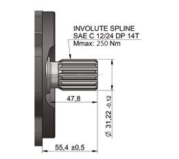
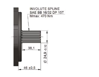
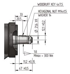
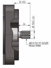
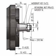
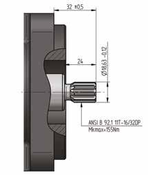
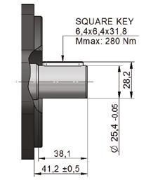
19 CASCADE GROUP 3 I TECHNICAL INFORMATION 19 Shaft types BA AA SE SC SH S0 SV S3


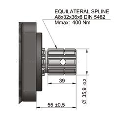
20 20 CASCADE GROUP 3 I TECHNICAL INFORMATION S7 PB PZ P3
21 CASCADE GROUP 3 I TECHNICAL INFORMATION 21 Combinations of flanges and shafts Shaft Type Model Flange Type SAE-A SAE-B 2 bolt SAE-B 4 bolt SAE-C 2 bolt SAE-C 4+2 bolt ISO square AA BB B4 C2 C6 II R6 1:8 Tapered Shaft BA a a a 1:5 Tapered Shaft AA a a a Spline SAE A 9T SE S a a a a Spline SAE A 11T SC S a a a a Spline SAE B 13T SH S S S a a Spline SAE C 14T * SO a a S S Spline SAE BB 15T SV a S S a a Spline DIN 5462 S3 S Spline DIN 5480 * S7 S Cylindric SAE B 7/8" PB a S S a a Cylindric SAE BB 1" PZ a S S a a Cylindric SAE C 1-1/4" * P3 a a S S * Only available with ORB S-Standard a - Available
![22 CASCADE GROUP 3 I TECHNICAL INFORMATION Port types Metric thread according to ISO 6149 Displacement Inlet Outlet [cm 3 ] A B C D A B C D Cascade 3 17-51 DE M 33x2 18 40 DB M 27x2 16 33 1 1 Cascade](/docs-images/84/89473117/images/22-1.jpg "3 51-71 DF M 48x2 22 56 DE M 33x2 18 40 BSPP pipe thread according to ISO 228-1 Displacement Inlet Outlet [cm 3 ] A B C D A B C D Cascade3 17-34 F6 G 1 18 45 F5 G 3/4 16 39 1 1 Cascade3 34-71 F7 G 1")
![1/4 24 58 F6 G 1 18 45 UNF thread according to SAE Displacement Inlet Outlet [cm 3 ] A B C D A B C D Cascade3 17-34 E8 1 5/16 12UN 49 E6 1 1/16 12UN 41 19 1 19 1 Cascade3 34-71 E9 1 5/8 12UN 58 E8 1](/docs-images/84/89473117/images/22-2.jpg "5/16 12UN 49 Flanged fittings according to DIN Displacement [cm3] Inlet Outlet E F G H E F G H BO 26 M10 51 BM 20 40 Cascade3 17-51 16 M8 16 BN 25 M8 55 BA 18 55 Cascade3 10-17 B7 20 M6 13 40 B5 15")
22 22 CASCADE GROUP 3 I TECHNICAL INFORMATION Port types Metric thread according to ISO 6149 Displacement Inlet Outlet [cm 3 ] A B C D A B C D Cascade DE M 33x DB M 27x Cascade DF M 48x DE M 33x BSPP pipe thread according to ISO Displacement Inlet Outlet [cm 3 ] A B C D A B C D Cascade F6 G F5 G 3/ Cascade F7 G 1 1/ F6 G UNF thread according to SAE Displacement Inlet Outlet [cm 3 ] A B C D A B C D Cascade E8 1 5/16 12UN 49 E6 1 1/16 12UN Cascade E9 1 5/8 12UN 58 E8 1 5/16 12UN 49 Flanged fittings according to DIN Displacement [cm3] Inlet Outlet E F G H E F G H BO 26 M10 51 BM Cascade M8 16 BN 25 M8 55 BA Cascade B7 20 M B5 15 M Note: Available only as side ports Flanged fittings according to SAE, metric thread Displacement Inlet Outlet [cm 3 ] E F G H I E F G H I Cascade M M M10 22 Cascade M M M Cascade M M M Cascade3 (single Inlet on multile pump) Note: Available only as side ports M M
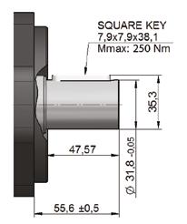
23 CASCADE GROUP 3 I TECHNICAL INFORMATION 23 Flanged fittings according to SAE, UNC thread Displacement Inlet Outlet [cm 3 ] E F G H I E F G H I Cascade A /8-16 UNC-2B A /8-16 UNC-2B 22 Cascade A /16-14 UNC-2B A Cascade A /2-13 UNC-2B A /16-14 UNC-2B Cascade3 (single Inlet on multile pump) A /2-13 UNC-2B Note: Available only as side ports Flanged fittings cross Displacement [cm 3 ] Cascade Inlet Outlet E F G H E F G H CA 26 M C M8 CP 25 M CO Note: Available only as side ports Tube Inlets Displacement [cm 3 ] Inlet A Cascade T1 25,4 27,6 Cascade T2 31,7 29,7 Cascade T3 38,1 31,5 Cascade 3 tandems/triples (single inlet) T4 50,8 29,7 D Drain ports: Case Drain Options Dimension Port Type N N/A No Drain 1 M16x1.5 Metric ORB 2 M18x1.5 Metric ORB 4 G 1/4" BSP/GAS 5 G 3/8" BSP/GAS 6 G 1/2" BSP/GAS 8 9/16"-18 UNF SAE ORB


24 24 CASCADE GROUP 3 I TECHNICAL INFORMATION Q (Quad ports) options: In case of quad ports, there are both rear and side ports present. Rear and side inlet of the same type and size are specified by position E in the model code, rear and side outlet of the same type and size are specified by position I in the model code. The products with quad port configuration are delivered with rear ports fitted with sealed metal plugs. Outrigger bearings The need for an additonal outrigger bearing depends on many factors including but no limited to magnitude of external force, direction of external force, point of effect on the shaft, load cycle etc. When in doubt if an outrigger bearing is necessary, contact Turolla technical support with application parameters. Type M (Medium duty bearing) Type H (Heavy duty bearing) Type I (ISO bearing) Note: Available only with ISO Flange (II)
25 CASCADE GROUP 3 I TECHNICAL INFORMATION 25 Aux pads Type 1 (accomodates SAE-A flange, 9T shaft) Type 2 (accomodates SAE-A flange, 11T shaft)

26 26 CASCADE GROUP 3 I TECHNICAL INFORMATION Configuration examples CAS-1-R-BB-SH BN-BA-R-N-N-NNN-NNN CAS-1-L-BB-SH BN-BA-R-N-N-NNN-NNN CAS-1-R-BB-SH BN-BA-R-N-N-NNN-NNN CAS-1-L-BB-SH BN-BA-R-N-N-NNN-NNN CAS-1-R-BB-SH BN-BA-R-N-N-NNN-NNN CAS-1-L-BB-SH BN-BA-R-N-N-NNN-NNN CAS-1-R-BB-SH BN-BA-R-N-N-NNN-NNN CAS-1-L-BB-SH BN-BA-R-N-N-NNN-NNN CAS-1-R-BB-SH BN-BA-R-N-N-NNN-NNN CAS-1-L-BB-SH BN-BA-R-N-N-NNN-NNN CAS-1-R-BB-SH BN-BA-R-N-N-NNN-NNN CAS-1-L-BB-SH BN-BA-R-N-N-NNN-NNN Model R L R L R L R L R L R L DIRECT. OF ROT DISPLA- MIN. MAX. A B C CEMENT SPEED DIMENSION [cm 3 /1] [min -1 ] [mm]


27 CASCADE GROUP 3 I TECHNICAL INFORMATION 27 CAS-2-R-BB-SH F7-F F6-F5-R-N-N-N-N-N-NNN CAS-2-L-BB-SH F7-F F6-F5-R-N-N-N-N-N-NNN CAS-2-R-BB-SH F7-F F6-F5-R-N-N-N-N-N-NNN CAS-2-L-BB-SH F7-F F6-F5-R-N-N-N-N-N-NNN CAS-2-R-BB-SH F7-F F6-F5-R-N-N-N-N-N-NNN CAS-2-L-BB-SH F7-F F6-F5-R-N-N-N-N-N-NNN CAS-2-R-BB-SH F7-F F6-F5-R-N-N-N-N-N-NNN CAS-2-L-BB-SH F7-F F6-F5-R-N-N-N-N-N-NNN CAS-2-R-BB-SH F7-F F6-F5-R-N-N-N-N-N-NNN CAS-2-L-BB-SH F7-F F6-F5-R-N-N-N-N-N-NNN CAS-2-R-BB-SH F7-F F6-F5-R-N-N-N-N-N-NNN CAS-2-L-BB-SH F7-F F6-F5-R-N-N-N-N-N-NNN Model R L R L R L R L R L R L DIRECT. OF ROT ,5 372, ,5 115,5 319,5 360, , , ,5 104,5 301,5 342, ,5 333, ,5 97,5 282,5 323,7 DISPLA- CEMENT [cm 3 /1] MIN. MAX. A1 A2 B C SPEED [min -1 ] DIMENSION [mm]
28 28 CASCADE GROUP 3 I TECHNICAL INFORMATION Notes
29 CASCADE GROUP 3 I TECHNICAL INFORMATION 29 Notes
30 Local address Italy Via Natale Salieri, Castel San Pietro Terme Bologna, Italia Phone: U.S.A East 13th Street Ames, IA 50010, USA Phone:
CAST IRON GEAR PUMPS AND MOTORS Dolomites Group 3 l Technical Information
 CAST ION GEA PUMPS AND MOTOS Dolomites Group 3 l Technical Information 2 dolomites 3 I TECHNICA INFOMATION History of revisions Date Page Changed ev. March 2015 - First edition - September 2016 - Second
GEAR PUMPS Group 3 l Technical Information
 GEAR PUMPS Group 3 l Technical Information 2 GROUP 3 GEAR PUMPS I TECHNICAL INFORMATION History of revisions Date Page Changed Rev. 28, June 2010 - First edition A 24, Feb 2011 1,2,11,32 Covers to blue
shhark continuum PUMPS Group 1 l Technical Information
 shhark continuum PUMPS Group 1 l Technical Information 66M 88Y 55K 77C 33M 50C 100Y 66M 88Y 2 GROUP 1 shhark continuum PUMPS I TECHNICAL INFORMATION History of revisions Date Page Changed Rev. May 2016
GEAR PUMPS Group 4 l Technical Information
 GEAR PUMPS Group 4 l Technical Information 2 GROUP 4 GEAR PUMPS I TECHNICAL INFORMATION History of revisions Date Page Changed Rev. 28, June 2010 - First edition A 30, Sept 2013 ALL Layout and options
Gear Motors Group 1, 2 and 3. Technical Information. OpenCircuitGear MEMBER OF THE SAUER-DANFOSS GROUP
 Gear Motors Group 1, 2 and 3 OpenCircuitGear Technical Information Gear Motors Group 1, 2 and 3 General Information Overview The Turolla OCG Gear Motors is a range of peak performance fixed displacement
Group 3 Gear Pumps. Technical Information. OpenCircuitGear MEMBER OF THE SAUER-DANFOSS GROUP
 Group 3 Gear Pumps OpenCircuitGear Technical Information General Information History of revisions Table of revisions Date Page Changed Rev. 28, June 21 - First edition A 24, Feb 211 1,2,11, 32 Covers to
Group 1 Gear Pumps. Technical Information. OpenCircuitGear MEMBER OF THE SAUER-DANFOSS GROUP
 Group Gear Pumps OpenCircuitGear Technical Information General Information History of revisions Table of revisions Date Page Changed Rev., June - First edition A, Feb,,, Covers to blue color, TurollaOCG
Group 3 Gear Pumps. Technical Information. OpenCircuitGear MEMBER OF THE SAUER-DANFOSS GROUP
 Group 3 Gear Pumps OpenCircuitGear Technical Information General Information History of revisions Table of revisions Date Page Changed Rev. 28, June 21 - First edition 24, Feb 211 1,2,11, 32 Covers to
Group 1 Gear Pumps. Technical Information. OpenCircuitGear MEMBER OF THE SAUER-DANFOSS GROUP
 Group 1 Gear Pumps OpenCircuitGear Technical Information General Information History of revisions Table of revisions Date Page Changed Rev., June 1 - First edition Reference documents Literature reference
GEAR PUMPS Group 3 l Technical Information
 GER PUMPS Group 3 l Technical Information 2 GROUP 3 GER PUMPS I TECHNICL INFORMTION History of revisions Date Page Changed Rev. 28, June 21 - First edition 24, Feb 211 1,2,11,32 Covers to blue color, Turolla
Group 1. Gear Pumps Technical Information
 Group Gear Pumps Technical Information Group Family of Gear Pumps SAUER-SUNDSTRAND High performance gear pumps are fixed displacement pumps which consist of the pump housing, drive gear, driven gear, DU
Group 2 Gear Pumps. Technical Information. OpenCircuitGear MEMBER OF THE SAUER-DANFOSS GROUP
 Group 2 Gear Pumps OpenCircuitGear Technical Information General Information History of revisions Table of revisions Date Page Changed Rev. 28, June 21 - First edition A 24, Feb 211 1, 2, 12, 44 Covers
GEAR PUMPS Group 2 l Technical Information
 GEAR PUMPS Group 2 l Technical Information 2 GROUP 2 GEAR PUMPS I TECHNICAL INFORMATION History of revisions Date Page Changed Rev. 28, June 21 - First edition A 24, Feb 211 1, 2, 12, 44 Covers to blue
shhark Aluminum Low Noise Gear Pump Group 2 l Technical Information
 shhark luminum Low Noise Gear Pump Group 2 l Technical Information 2 shhark GROUP 2 I TECHNICL INFORMTION History of revisions Date Page Changed Rev. March 216 LL First release Reference documents Title
Gear Pumps Group 0 and Group 1 l Technical Information
 Gear Pumps Group 0 and Group 1 l Technical Information 2 GROUP 0 and Group 1 GER PUMPS I TECHNICL INFORMTION History of revisions Date Page Changed Rev. 24, June 2010 - First edition 24, Feb 2011 1,2,10,68
GEAR PUMPS D Series and XD Series Gear Pumps l Technical Information
 GEAR PUMPS D Series and XD Series Gear Pumps l Technical Information 2 D SERIES AND XD SERIES GEAR PUMPS I TECHNICAL INFORMATION History of Revisions Date Page Changed Rev. Jun, 2010 - First edition A
Group 1 Gear Pumps Technical Information General Information
 General Information OVERVIEW The Sauer-Danfoss Group is a range of peak performance fixed-displacement gear pumps. Constructed of a high-strength extruded aluminum body with aluminum cover and flange,
GEAR MOTORS D Series Gear Motors including Fan Drive l Technical Information
 GEAR MOTORS D Series Gear Motors including Fan Drive l Technical Information 2 D SERIES GEAR MOTORS I TECHNICAL INFORMATION History of revisions Date Page Changed Rev. Feb. 2009 - First edition AA Nov.
D Series. Technical Information. OpenCircuitGear. Cast Iron Gear Pumps MEMBER OF THE SAUER-DANFOSS GROUP
 D Series Cast Iron Gear Pumps Revisions History of Revisions Table of Revisions Date Page Changed Rev. Jun, 2010 - First edition A December 2010 all Major update B April 2011 all Major update C October
Group 2 Gear Pumps. Technical Information. OpenCircuitGear MEMBER OF THE SAUER-DANFOSS GROUP
 Group 2 Gear Pumps OpenCircuitGear Technical Information General Information History of revisions Table of revisions Date Page Changed Rev. 28, June 21 - First edition 24, Feb 211 1, 2, 12, 44 Covers to
D Series Gear Motors Including Fan Drive. Technical Information
 D Series Gear Motors Including Fan Drive Technical Information Revisions History of Revisions Table of Revisions Date Page Changed Rev. February 09 - First edition AA 09 Sauer-Danfoss. All rights reserved.
AXIAL PISTON PUMPS SHPV SECTIONAL VIEW
 AXIAL PISTON PUMPS SHPV SECTIONAL VIEW 2 SYSTEM CIRCUIT PUMP AND MOTOR CIRCUIT working loop (high pressure) working loop (low pressure) control fluid suction line case drain fluid Above figure shows schematically
AXIAL PISTON PUMPS SHPV SECTIONAL VIEW
 AXIAL PISTON PUMPS SHPV SECTIONAL VIEW 2 AXIAL PISTON PUMPS SHPV SYSTEM CIRCUIT PUMP AND MOTOR CIRCUIT working loop (high pressure) working loop (low pressure) control fluid suction line case drain fluid
Series 20 Axial Piston Pumps. Technical Information
 Series 20 Axial Piston Pumps Technical Information General Description INTRODUCTION Sauer-Danfoss a world leader in hydraulic power systems has developed a family of axial piston pumps. DESCRIPTION Sauer-Danfoss
Series 20 Axial Piston Pumps. Technical Information
 Series 20 Axial Piston Pumps Technical Information General Description INTRODUCTION Sauer-Danfoss a world leader in hydraulic power systems has developed a family of axial piston pumps. DESCRIPTION Sauer-Danfoss
3PE. Aluminium gear pumps. Technical Catalogue E IM03
 3PE Aluminium gear pumps Technical Catalogue GEAR PUMPS E - B - C SERIES General Features GEAR PUMPS SALAMI gear pumps are available with displacements from 1.4 cm 3 /rev to 99 cm 3 /rev (from 0.09 cu.in/rev
QHD1 TABLE OF CONTENTS. Gear Pump Catalogue Table of Contents
 TABE OF CONTENTS Table of Contents DESCIPTION... 2 BASIC PATS OF PUMP... 2 PAAMETE TABE... 3 FOMUAS USED FO CACUATION... 4 PUMP EFFICIENCIES... 4 WOKING IQUID... 5 PESSUE OAD... 5 OTHE EQUIEMENTS... 6
Vickers. Vane Pumps. Double Thru-drive Vane Pumps. High speed, high pressure VQT Series for mobile equipment. Released 7/93
 Vickers Vane Pumps Double Thru-drive Vane Pumps High speed, high pressure VQT Series for mobile equipment Released 7/93 612 Introduction Double VQT high performance pumps are fixed displacement units that
FAN DRIVE GEAR MOTORS Group 2 and Group 3 l Technical Information
 FN DRIVE GER MOTORS Group 2 and Group 3 l Technical Information 2 FN DRIVES GER MOTORS I TECHNICL INFORMTION History of revisions Date Page Changed Rev. 28, Jun 21 - First edition 16, Feb 211 ll Covers
External Gear Pumps Series F
 External Gear Pumps Series F RA 10089/08.11 Replaces: RA 10097 1/60 AZPF-... Fixed pumps Size 4.0...28 cm 3 /rev (.25-1.71 in 3 /rev) Overview of contents Contents Page General 2 Product overview 3 single
Series TMM Axial Piston Motor. Technical Information
 Series TMM Axial Piston Motor Technical Information General Description GENERAL DESCRIPTION These motors are designed primarily to be combined with other products in closed circuit systems to transfer
Displacement from 10 to 100 ccm Pressure up to 290 bar Speed from 400 to 3200 RPM GEAR MOTORS QM2
 Displacement from 10 to 100 ccm Pressure up to 290 bar Speed from 400 to 3200 PM GEA MOTOS QM2 Gear Motor Catalogue QM2 TABLE OF CONTENTS DESCIPTION......................................................................................................................
5.2 MEDIUM HEAVY DUTY SERIES SIZE 3
 .2 MEDIUM HEAVY DUTY SERIES SIZE 3 CONTENTS PGI101 Ordering Code.2.1 Medium Heavy Duty Series Technical Information.2.2 Specifications.2.3 Hydraulic fluids.2.4 Viscosity range.2. Temperature range.2.6
TAP Gear Pumps Technical Information Tap Gear Pumps Standard Flange. OpenCircuitGear. Installation dimensions. Specification Data
 Tap 60-00 Gear Pumps Standard Flange Installation dimensions Tapered Shaft Parallel Shaft Splined shaft Type Capacity cc/rev Displacement at 1000 RPM litres/min. Max pressure bar Max speed rev/min. A B
AXIAL PISTON MOTORS SHMF
 SECTIONAL VIEW Purge relief valve High pressure relief valves (adjustable) Cylinder block assembly Shaft seal Output shaft Valve block Shuttle valve Swashplate 2 SYSTEM CIRCUIT PUMP AND MOTOR CIRCUIT working
US version. Drain connection
 Versions OMT Versions Mounting flange Standard flange Shaft Port size Europea n version US version Drain connection Check valve Low pressure release High pressure release Cyl. 4 mm G 3/4 X Yes Yes OMT
Distribuíção, revenda emanutenção. CatálogosOnline. (11) (11)
 (11)") Distribuíção, revenda emanutenção CatálogosOnline (11)4174-3300-(11)4765-6775 www.hmc.com.br MAKING MODERN LIVING POSSIBLE Technical Information Axial Piston Pumps Series 20 powersolutions.danfoss.com
Distribuíção, revenda emanutenção CatálogosOnline (11)4174-3300-(11)4765-6775 www.hmc.com.br MAKING MODERN LIVING POSSIBLE Technical Information Axial Piston Pumps Series 20 powersolutions.danfoss.com
External gear pump Series G
 External gear pump Series G RE 10 093/04.14 Replace RE 10 093/06.13 AZPG-22 Fixed pumps V = 22.5...100 cm 3 / rev Overview of contents Contents Page General 2 Product overview 3 Ordering code single pumps
AP212 Gear Pumps. Standard and Low Noise series. Reference: 200-P EN-03 1/60. Issue:
 Gear Pumps Standard and Low Noise series Reference: 2-P-99123-EN-3 Issue: 9.215 1/6 Contents Page 1 General information... 4 1.1 External gear pumps components... 5 1.2 Example of typical sound pressure
Service manual. Gear pumps - series QHD
 Service manual Gear pumps - series QHD 1. Basic description Gear pumps serve to transform mechanical energy into pressure energy of a liquid. The series pumps are designed primarily for use in mobile hydraulics
from 350 to 3200 RPM GEAR PUMPS QHD
 Displacement Pressure Speed from 10,00 to 82,00 ccm up to 320 bar from 350 to 3200 PM GEA PUMPS TABE OF CONTENTS Table of Contents DESCIPTION... 2 BASIC PATS OF PUMP... 2 PAAMETE TABE... 3 FOMUAS USED
TPV Variable Displacement Closed Loop System Axial Piston Pump THE PRODUCTION LINE OF HANSA-TMP HT 16 / M / 852 / 0815 / E
 HYDRAULIC COMPONENTS HYDROSTATIC TRANSMISSIONS GEARBOXES - ACCESSORIES Certified Company ISO 9001-14001 ISO 9001 Via M. L. King, 6-41122 MODENA (ITALY) Tel: +39 059 415 711 Fax: +39 059 415 729 / 059 415
AP212HP Cast Iron Gear Pumps
 Cast Iron Gear Pumps Standard and Low Noise series Reference: 200-P-991236-EN-01 Issue: 09.2016 1/56 Contents Page 1 General information... 5 1.1 External gear pumps components... 6 1.2 Technical data...
Series ASC Anti Spin Control Valve
 MAKING MODERN LIVING POSSIBLE Technical Information Series ASC Anti Spin Control Valve powersolutions.danfoss.com Revision history Table of revisions Date Changed Rev March 2014 Converted to Danfoss layout
UŽSISAKYKITE internetu telefonu el. paštu
 Features Axial piston pump MA10VO in swashplate design is used in open loop circuits. Flow is proportional to drive speed and displacement. By adjusting the position of the swashplate it is possible to
Group 2 Gear Pumps Technical Information
 Group 2 Gear Pumps Technical Information Group 2 Family of Gear Pumps SUER-SUNDSTRND High performance gear pumps are fixed displacement pumps which consist of the pump housing, drive gear, driven gear,
Technical Information Series 45 G Frame powersolutions.danfoss.com
 MAKING MODERN LIVING POSSIBLE Technical Information Series 45 G Frame powersolutions.danfoss.com Contents Frame G Design... 4 Specifications... 5 Performance G74B... 6 Performance G9C... 7 Order code...
HYDRAULIC MOTORS MLHH
 HYDRAULIC APPLICATION» Conveyors» Feeding mechanism of robots and manipulators» Metal working machines» Textile machines» Machines for agriculture» Food industries» Mining machinery etc. CONTENTS Specification
PVE /117 ED VARIABLE DISPLACEMENT VANE PUMPS WITH DIRECT PRESSURE ADJUSTMENT SERIES 30 OPERATING PRINCIPLE TECHNICAL SPECIFICATIONS
 14 110/117 ED PVE VARIABLE DISPLACEMENT VANE PUMPS WITH DIRECT PRESSURE ADJUSTMENT OPERATING PRINCIPLE The PVE pumps are variable displacement vane pumps with direct pressure regulator. The pump group
HYDRAULIC MOTORS MM APPLICATION OPTIONS CONTENTS GENERAL MOTORS
 HYDRAULIC APPLICATION Conveyors Textile machines Mining machinery Machine tools Ventilators Construction plant equipment and access platforms etc. CONTENTS Specification data... 5 Function diagrams...
Variable displacement axial piston pumps,
 Variable displacement axial piston pumps, Edition: 04/04.2000 Replaces: 04/10.99 DISPLACEMENTS From To PRESSURE Max. continuous Max. intermittent Max. peak 29 cm 3 /rev 73 cm 3 /rev 280 bar 315 bar 350
C9: BMM, BMP, BMR, BMH, BMJ Series & Valves CONTENT. Usage Guide 2. BMM Series Hydraulic Motors 3. BMP Series Hydraulic Motors 11
 C9: BMM, BMP, BMR, BMH, BMJ Series & Valves CONTENT Usage Guide 2 BMM Series Hydraulic Motors 3 BMP Series Hydraulic Motors 11 BMR Series Hydraulic Motors 24 BMH Series Hydraulic Motors 35 BMJ Series Hydraulic
5.1 MEDIUM HEAVY DUTY SERIES SIZE 2
 .1 MEDIUM HEAVY DUTY SERIES SIZE 2 CONTENTS PGI100 Ordering Code.1.1 Medium Heavy Duty Series Technical Information.1.2 Specifications.1.3 Hydraulic fluids.1.4 Viscosity range.1. Temperature range.1.6
Vane Pumps. VMQ Series Vane Pumps For Industrial and Mobile Applications Displacements to 215 cm 3/ r (13.12 in 3 /r) Pressures to 260 bar (3800 psi)
 Pressures to 260 bar (3800 psi)") Vickers Vane Pumps VMQ Series Vane Pumps For Industrial and Mobile Applications Displacements to 215 cm 3/ r (13.12 in 3 /r) Pressures to 260 bar (3800 psi) 5008.00/EN/0596/A A.25 Introduction From the
Vickers Vane Pumps VMQ Series Vane Pumps For Industrial and Mobile Applications Displacements to 215 cm 3/ r (13.12 in 3 /r) Pressures to 260 bar (3800 psi) 5008.00/EN/0596/A A.25 Introduction From the
TABLE OF CONTENTS. Gear Pump Catalogue Table of Contents
 TABE OF CONTENTS Table of Contents DESCIPTION... 2 BASIC PATS OF PUMP... 2 PAAMETE TABE... 3 FOMUAS USED FO CACUATION... 4 PUMP EFFICIENCIES... 4 WOKING IQUID... 5 PESSUE OAD... 5 DIECTION OF OTATION...
Genuine Metaris MA10VO/VSO Technical Catalog. Variable Displacement Piston Pump - A10V Series 31 & 52
 Genuine Metaris MA10VO/VSO Technical Catalog www.metaris.com Contents General Series MA10VO/VSO Series 31 4 Page Features 4 Technical Data 5 Performance Information 6 Model Code Breakdown 9 Fluid Info
D SERIES HYDRAULIC PUMP
 uk distributor for D SERIES HYDRAULIC PUMP quality products for mechanical & fluid power jbj Techniques Limited, www.jbj.co.uk Introduction to Concentric D Series Hydraulic Pumps Concentric offers one
RA / Internal Gear Pump Model GP3, Series 3X Fixed Displacement. Typical application:
 Sizes 20 to 32 Internal Gear Pump Model GP3, Series 3X Fixed Displacement up to 5076 PSI 1.25 to 1.98 in 3 (350 bar) (20.6 to 32.5 cm 3 ) RA 10 234/07.97 Characteristics: Peak pressure of up to 5.076 PSI
Gear Pumps / Motors. Series PGP / PGM Fixed Displacement Pumps, Cast-Iron and Aluminium Designs
 Gear Pumps / Motors Series PGP / PGM Fixed Displacement Pumps, Cast-Iron and Aluminium Designs Table of contents Heavy-duty Pumps and Motors Series PGP, PGM Contents Page Series 500 Aluminium Table of
Catalog HY /NA. Catalog HY /NA. Parker Hannifin Corporation Hydraulic Pump Division Marysville, Ohio USA
 Catalog HY28-6/NA PV, PVT Series Piston Pumps Variable Volume Catalog HY28-6/NA 1 Catalog HY28-6/NA Notes Series PV 2 Catalog HY28-6/NA Introduction Series PV Quick Reference Data Chart Pump Delivery Approx.
External gear motor High Performance AZMB
 External gear motor High Performance AZMB RE 14027 Edition: 0.201 Platform B Fixed displacement Sizes 2.5 to 7.1 Continuous pressure up to 220 bar Intermittent pressure up to 2 bar Features Consistently
W1500 SERIES HYDRAULIC PUMP
 W1500 SERIES HYDRAULIC PUMP Concentric AB Innovation in Hydraulics PRESSURE (P1) 276 BAR (4000 PSI) (P2) 300 BAR (4400 PSI) SPEED 3300 RPM Min. 500 RPM at 4000 PSI (276 BAR) Continuous EFFICIENCY Overall
Axial Piston Variable Pump AA4VG
 Electric Drives and Controls Hydraulics Linear Motion and Assembly Technologies Pneumatics Service Axial Piston Variable Pump AA4VG RA 92003-A/06.09 1/64 Replaces: 03.09 Data sheet Series 32 Size 28...
6.3 SIZE 2. Ordering Code External Gear Pump
 6.3 SIZE 2 CONTENTS PGE12 Ordering Code 6.3.1 External Gear Pump Technical Information 6.3.2 Specifications 6.3.3 Hydraulic fluids 6.3.4 Viscosity range 6.3.5 Temperature range 6.3.6 Seals 6.3.7 Filtration
GEAR PUMPS. from 500 to 4000 RPM
 Displacement Pressure Speed from 2,00 to 15,00 ccm up to 310 bar from 500 to 4000 PM GEA PUMPS TABE OF CONTENTS Table of Contents TABE OF CONTENTS... 1 BASIC DESCIPTION... 2 BASIC PATS... 2 PAAMETE TABE...
3.5PC. Aluminium gear pumps. Technical Catalogue E IM04
 3.5PC Aluminium gear pumps Technical Catalogue GEAR PUMPS E - B - C SERIES General Features GEAR PUMPS SALAMI gear pumps are available with displacements from 1.4 cm 3 /rev to 99 cm 3 /rev (from 0.09
Hydraulic gear pumps and motors
 PL 01 T E DISPLACEMENTS From To Hydraulic gear pumps and motors 0.07 in 3 /rev (1.07 cm 3 /rev) 5.56 in 3 /rev (91.10 cm 3 /rev) through bore aluminum body PRESSURE Max. Continuous Max. Intermittent Max.
Service manual. Gear pumps - series T3S
 Service manual Gear pumps - series T3S 1. Basic description Gear pumps serve to transform mechanical energy into pressure energy of a liquid. T3S line pumps with external helical gearing can be used -
SCM SAE. Other advantages: Sunfab s SCM SAE is a range of robust axial piston motors especially suitable for mobile hydraulics.
 Sunfab s SCM 010-130 SAE is a range of robust axial piston motors especially suitable for mobile hydraulics. SCM 010-130 SAE is of the bent-axis type with spherical pistons. The design results in a compact
MOTOR SCM ISO
 MOTOR SCM 012-130 ISO SCM 012-130 ISO is a range of robust axial piston motors especially suitable for mobile hydraulics. SCM 012-130 ISO is of the bent-axis type with spherical pistons. The design results
GEAR MOTORS. from 500 to 4000 RPM
 Displacement Pressure Speed from 2,00 to 15,00 ccm up to 300 bar from 500 to 4000 PM GEA MOTOS TAE OF CONTENTS Table of Contents DESCIPTION... 2 ASIC PATS... 2 PAAMETE TAE... 3 FOMUAS USED FO CACUATION...
Axial Piston Pump Series PV Design 45 Variable Displacement. Catalogue HY /UK February 2007
 Design 45 Variable Displacement February 2007 Introduction With thru drive for single and multiple pumps Swash plate type for open circuit Technical Features Low noise level Fast response (eg. PV046: upstroke
Series 90 Axial Piston Pumps. Technical Information
 Series 90 Axial Piston Pumps Technical Information Revisions History of Revisions Table of Revisions Date Page Changed Rev. March 2010 Various Fix O-ring dimensions in dimension drawings FE December 2009
Series PVP Variable Volume Piston Pumps
 Series PVP Variable Volume Piston Pumps Catalog HY28-2661-CD/US zp2 hpm12-1.p65, lw, jk 1 Notes Series PVP hpm12-1.p65, lw, jk 2 Introduction Series PVP Series Sizes 6-14 Phased Out For Reference Only
GP PUMP SIZE GP1 GP2 GP3 Displacement range cm 3 /rev clockwise, anticlockwise or reversible (seen from the shaft side)
") 11 1/117 ED GP EXTERNA GEAR PUPS OPERATING PRINCIPE The GP pumps are fixed displacement external gear pumps with axial clearance compensation. They give high volumetric efficiency even with high operating
11 1/117 ED GP EXTERNA GEAR PUPS OPERATING PRINCIPE The GP pumps are fixed displacement external gear pumps with axial clearance compensation. They give high volumetric efficiency even with high operating
SCM SAE. Other advantages: Sunfab s SCM SAE is a range of robust axial piston motors especially suitable for mobile hydraulics.
 Sunfab s SCM 010-130 SAE is a range of robust axial piston motors especially suitable for mobile hydraulics. SCM 010-130 SAE is of the bent-axis type with spherical pistons. The design results in a compact
HYDRAULICS VINCKE HYDRAULIC PUMPS
 VINCKE HYDRAULIC PUMPS TECH-VHP200.1 index 3 link to your page / link a su página Gear pumps Introduction 3 Group 0 3 Group 1 3 Group 2 3 Group 3 4 6 7 12 18 Variable displacement pumps 21 Hand pumps 3
» Feeding mechanism of robots and manipulators» Metal working machines» Textile machines» Machines for agriculture» Food industries.
 HYDRAULIC MH APPLICATION» Conveyors» Feeding mechanism of robots and manipulators» Metal working machines» Textile machines» Machines for agriculture» Food industries» Mining machinery etc. CONTENTS Specification
OMEW Standard and with Low Speed Option. Orbital Motors. Technical Information
 Standard and with Low Speed Option Orbital Motors Technical Information Contents Revision History Table of Revisions Date Page Changed Rev Jan 2009 Many major change BA Mar 2010 16 Japan location BB Contents
» Feeding mechanism of robots and manipulators» Metal working machines» Textile machines» Machines for agriculture» Food industries
 HYDRAULIC HW APPLICATION» Conveyors» Feeding mechanism of robots and manipulators» Metal working machines» Textile machines» Machines for agriculture» Food industries» Grass cutting machinery etc. CONTENTS
MOTOR SCM M2
 MOTOR SCM 025 108 M2 Sunfab SCM M2 is a range of robust axial piston motors especially suitable for winch-, slewing-, wheeland track drives. Sunfab SCM M2 is of the bent-axis type with spherical pistons.
Series 20 Axial Piston Motors. Technical Information
 Series 20 xial Piston Motors Technical Information General Description INTRODUCTION Sauer-Danfoss a world leader in hydraulic power systems has developed a family of axial piston motors. DESCRIPTION Sauer-Danfoss
Axial Piston Fixed Motor A2FM
 Axial Piston Fixed Motor A2FM RE 91001/06.2012 1/46 Replaces: 09.07 Data sheet Series 6 Size Nominal pressure/maximum pressure 5 315/350 bar 10 to 200 400/450 bar 250 to 1000 350/400 bar Open and closed
HYDRAULIC MOTORS EPMT
 HYDRAULIC APPLICATION Conveyors; Metal working machines; Machines for agriculture; Road building machines; Mining machinery; Food industries; Special vehicles; Plastic and rubber machinery etc. CONTENTS
P90 VARIABLE DISPLACEMENT PUMP T E C H N I C A L C A T A L O G
 P90 VARIABLE DISPLACEMENT PUMP T E C H N I C A L C A T A L O G Variable displacement pump POCLAIN HYDRAULICS Design Slider block Swashplate hold-down Servo piston Servo arm Piston Slipper Displacement
Veljan Gear Pumps. E' Series Features:-
 E' Series Features:- Heavy duty sleeve bushing design in a small frame size Displacements from 43.5cc/rev to 146.5cc/rev Working pressures up to 240bar Speeds up to 3500rpm Flows up to 38.7gpm High strength
SCM ISO. SCM ISO is a range of robust axial piston motors especially suitable for mobile hydraulics.
 SCM 010-130 ISO is a range of robust axial piston motors especially suitable for mobile hydraulics. SCM 010-130 ISO is of the bent-axis type with spherical pistons. The design results in a compact motor
General Gear Pumps and Gear Motors. Technical Information
 General Gear Pumps and Gear Motors Technical Information Overview This manual offers the Sauer-Danfoss customer summarized technical information on all standard Sauer-Danfoss gear pumps and motors and
Series 20 Axial Piston Motors. Technical Information
 Series 20 xial Piston Motors Technical Information General Description INTRODUCTION Sauer-Danfoss a world leader in hydraulic power systems has developed a family of axial piston motors. DESCRIPTION Sauer-Danfoss
Gear Housing Widths 1.00" 1.25" 1.50" 1.75" 2.00" 2.25" 2.50" Gear Housing Widths / Flow Rate [ VGP - D Series ]
![Gear Housing Widths 1.00 1.25 1.50 1.75 2.00 2.25 2.50 Gear Housing Widths / Flow Rate [ VGP - D Series ]](/thumbs/76/74105930.jpg "Gear Housing Widths 1.00 1.25 1.50 1.75 2.00 2.25 2.50 Gear Housing Widths / Flow Rate [ VGP - D Series ]") 'D' Series Features:- Heavy duty sleeve bushing design in a small frame size Displacements from 20.6cc/rev to 104.2cc/rev Working pressures up to 240bar Speeds up to 3500rpm Flows up to 27.5gpm High strength
'D' Series Features:- Heavy duty sleeve bushing design in a small frame size Displacements from 20.6cc/rev to 104.2cc/rev Working pressures up to 240bar Speeds up to 3500rpm Flows up to 27.5gpm High strength
RA / Internal Gear Pump Model GP2, Series 2X Fixed Displacement. Typical application:
 Sizes 6.3 to 16 Internal Gear Pump Model GP2, Series 2X Fixed Displacement up to 576 PSI.397 to.98 in 3 (35 bar) (6.5 to 16 cm 3 ) RA 1 23/6.97 RA 1 23/6.97 Characteristics: Peak pressure of up to 576
TPV Variable Displacement Closed Loop System Axial Piston Pump HY-TRANS THE PRODUCTION LINE OF HANSA-TMP HT 16 / M / 501 / 1009 / E
 HYDRAULIC COMPONENTS HYDROSTATIC TRANSMISSIONS GEARBOXES - ACCESSORIES HY-TRANS THE PRODUCTION LINE OF HANSA-TMP Via M. L. King, 6-41122 MODENA (ITALY) Tel: +39 059 415 711 Fax: +39 059 415 729 / 059 415
Double Pump Operating Specifications
 Double Pump Operating Specifications Shaft End Pump Cover End Pump Typical Typical Typical Typical del. input del. input Delivery L/min kw Delivery L/min kw USgpm @ (USgpm) (hp) USgpm @ (USgpm) (hp) 12
TPV Variable Displacement Closed Loop System Axial Piston Pump THE PRODUCTION LINE OF HANSA-TMP HT 16 / M / 851 / 0813 / E
 HYDRAULIC COMPONENTS HYDROSTATIC TRANSMISSIONS GEARBOXES - ACCESSORIES THE PRODUCTION LINE OF HANSA-TMP Variable Displacement Closed Loop System CONTENTS General Information... Order Code... Manual Control
External gear pump Series G
 External gear pump Series G RE 1 93/8.7 AZPG-22 Fixed pumps V = 22.5...63 cm 3 /rev Overview of contents Contents Page General 2 Product overview 3 Ordering code single pumps 4 Ordering code multiple pumps
Variable displacement axial piston pumps,
 LVP 04 T E Variable displacement axial piston pumps, Edition: 04/04.2000 Replaces: 04/10.99 DISPLACEMENTS From To PRESSURE Max. continuous Max. intermittent Max. peak 29 cm 3 /rev 73 cm 3 /rev 280 bar
General Aluminum Gear Pumps and Motors. Technical Information. OpenCircuitGear MEMBER OF THE SAUER-DANFOSS GROUP
 General luminum Gear Pumps and Motors OpenCircuitGear MEMER OF THE SUER-DNFOSS GROUP Technical Information MEMER OF THE SUER-DNFOSS GROUP General luminum Gear Pumps and Motors General Information Overview
RE 91808/ AA4VSE Plug-in dual displacement motor. High pressure range. Series 10 Axial piston swashplate design, SAE model
 AA4VSE Plug-in dual displacement motor Series Axial piston swashplate design, SAE model RE 91808/09.90 RE 91808/09.90 Brueninghaus Hydromatik Size 250 Nominal pressure 350 bar Peak pressure 400 bar High
Series 45 Open Circuit Axial Piston Pumps. Technical Information. Displacement Piston. Swashplate. Piston. Tapered Roller Bearing
 Series 45 Open Circuit Axial Piston Pumps Technical Information Displacement Piston Piston Swashplate Tapered Roller earing Tapered Roller earing Valve Plate Cylinder lock Kit Shaft Seal General Description