L and K Frame Variable Motors. Technical Information
|
|
|
- Pierce Sims
- 5 years ago
- Views:
Transcription


1 L and K Frame Variable Motors Technical Information
2 Revisions Revisions Table of Revisions Date Page Changed Rev. April corrected the schematic drawings BE January removed displacement limiter setting F % BD April LV (41 pulses/rev) KV (44 pulses/rev) BC March changed 41 pulses/rev to 44 pulses/rev BB October 2006 Various Added Loop flushing valve and 5 bolt endcap B February First edition A 2008 Sauer-Danfoss. All rights reserved. Sauer-Danfoss accepts no responsibility for possible errors in catalogs, brochures and other printed material. Sauer-Danfoss reserves the right to alter its products without prior notice. This also applies to products already ordered provided that such alterations aren t in conflict with agreed specifications. All trademarks in this material are properties of their respective owners. Sauer-Danfoss and the Sauer-Danfoss logotype are trademarks of the Sauer-Danfoss Group L0627 Rev BE April 2008
3 Contents General description Basic Design... 5 Key features... 5 System circuit diagram... 6 Motor schematic diagrams... 6 Technical specifications Overview... 7 Features and options... 7 Specifications... 7 Operating parameters... 7 Fluid specifications... 7 Performance... 8 Operating parameters Fluids... 9 Viscosity... 9 Temperature... 9 Charge pressure... 9 Case pressure... 9 Pressure ratings...10 Speed ratings...10 System design parameters Installation...11 Filtration...11 Reservoir...11 Overpressure protection...11 Loop flushing...12 Charge flow...12 Charge pressure...12 Redundant braking system requirement...12 Series operation...12 Shaft loads...13 Duty cycle and bearing life...13 Hydraulic equations helpful for motor selection L0627 Rev BE April
4 Contents Product coding Name plate...15 Model code...16 Features and options Speed sensor...18 Output shafts...18 Lubrication of splined shafts...18 Loop flushing...19 Displacement limiters...22 Motor rotation...22 Controls...22 Brake release port (cartridge motors)...22 Control orificing...22 Installation drawings SAE-B mount (LV/KV)...23 Cartridge (LC/KC) L0627 Rev BE April 2008
 and two housing (mounting) configurations.")
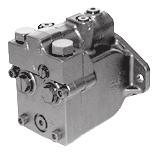
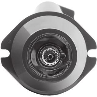
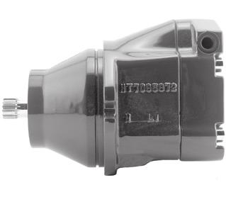
5 General description Basic Design The L and K Frame variable motors are light to medium power two-position axial piston motors incorporating an integral servo piston. They are designed for operation in closed circuit applications. The L and K Frame motors consist of five unique rotating groups (displacements) and two housing (mounting) configurations. An SAE-B, two-bolt, and a cartridge style (for space-optimized gearbox mounting) configurations are available for each frame. Maximum speeds and maximum applied pressures for each displacement vary. The standard control is a direct acting single line hydraulic control. For SAE-B mount motors a two line control is also available. The integral servo piston controls motor displacement. The motor is spring biased to maximum displacement and hydraulically shifted to minimum displacement. Minimum and maximum displacement can be set with fixed internal stops. The large diameter servo piston allows smooth acceleration and deceleration with relatively large circuit orificing. The motor is ideally configured for installations requiring compact packaging and optimized plumbing, such as wheel ends. One face of the motor contains all hydraulic porting. Two standard porting configurations are available: twin radial (side) or axial (end) O-ring boss main ports. Cross section, SAE-B mount Bias spring Minimum angle stop Cylinder block Servo piston Swashplate Output shaft Cross section, cartridge mount Cylinder block Servo piston Bias spring Swashplate Output shaft Endcap Piston Valve plate Slipper Shaft seal Bearing P E Endcap Valve plate Piston Shaft seal Bearing Slipper P E Key features Five displacements allow the optimum selection of hydraulic motor for the lowest possible installed cost. SAE-B, two-bolt, and cartridge mounting configurations available. Short and compact; fits into existing installation with improved porting. Three clean sides with superior clearance and access to mounting bolts. High Efficiency - nine piston rotating groups with 18 degree maximum angle. Versatility - working displacement range of 3.4:1 with a minimum angle option to one degree overcenter (-1 ). Reliability - uses existing and proven technology. Worldwide service and technical support. 520L0627 Rev BE April
6 General description System circuit diagram Pictorial system diagram Control handle Heat exchanger bypass Reservoir Filter Motor displacement control valve Displacement control valve Heat exchanger Cylinder block assembly Charge relief valve Displacement limiter Motor servo piston Bypass valve Input shaft Variable displacement pump Check valves w/ high pressure relief valve Charge pump Loop flushing module High loop pressure Case pressure Charge/low loop pressure Inlet pressure Cylinder block assembly Loop flushing relief valve Output shaft Motor swashplate P E The circuit above shows the LV/KV motor in a simple closed-loop hydrostatic propel application. The motor is driven by a Series 40 M46 axial piston pump with manual displacement control. The motor shown uses a single line hydraulic displacement control. Control pressure applied through an external control valve shifts the motor to minimum displacement, spring force returns the motor to maximum displacement in the absence of control input. Motor schematic diagrams Motor schematic, single line control M1 X1 A Motor schematic, dual line control M1 X1 X2 A MIN MIN B L2 B L2 M2 L1 P M2 L1 P L0627 Rev BE April 2008
7 Technical specifications Overview Specifications and operating parameters for L and K Frame motors are given here for quick reference. For additional information, see Operating parameters, page 10, Features and options, page 19 and Product coding, page 16. Features and options Mount SAE-B (LV/KV) Cartridge (LC/KC) Motor type Inline, axial piston, positive displacement, two-speed variable motors Displacement L: 25, 30, or 35 cm 3 [1.50, 1.83, or 2.14 in 3 ] K: 38 or 45 cm 3 [2.32 or 2.75 in 3 ] Rotation Installation position Bidirectional Discretionary: Housing must always be filled with hydraulic fluid Porting SAE O-ring boss, axial or twin radial SAE O-ring boss, twin radial Output shafts Splined 13 or 15 tooth 16/32 pitch, Splined 13 or 15 tooth 16/32 pitch in. straight keyed, and 1:8 taper Control options Single or dual line hydraulic control Single line hydraulic control Displacement limiter Speed sensor Loop Flushing Valve Fixed maximum and minimum displacement limiters available Available - refer to Features and options section Available - refer to Features and options section Specifications Parameter Unit L25 L30 L35 K38 K45 Displacement (maximum) cm 3 [in 3 ] 25 [1.50] 30 [1.83] 35 [2.14] 38 [2.32] 45 [2.75] Weight (cartridge and SAE-B) kg [lb] 15.4 [34] Mass moment of inertia of rotating components Theoretical torque kg m 2 [slug ft 2 ] N m/bar [lbf in/1000psi] [ ] 0.40 [244] [ ] 0.48 [293] [ ] 0.56 [347] [ ] 0.60 [366] [ ] 0.72 [439] Operating parameters Parameter Unit L25 L30 L35 K38 K45 System pressure Speed limit (at max. disp) Speed limit (at min. disp) continuous bar [psi] 210 [3045] maximum 415 [6020] 175 [2540] 350 [5075] 140 [2030] 280 [4060] 210 [3045] 415 [6020] 175 [2540] 350 [5075] continuous min -1 (rpm) maximum continuous maximum Case pressure continuous bar [psi] 2 [29] Shift pressure (single line control) maximum 6 [87] minimum bar [psi] 14 [203] maximum 69 [1000] Fluid specifications Ratings and data are based on operation with premium petroleum-based hydraulic fluids containing oxidation, rust, and foam inhibitors. Parameter Unit Minimum Continuous Maximum Viscosity mm 2 /sec (cst) [SUS] 7 [47] [70-278] 1600 [7500] Temperature C [ F] -40 [-40] 82 [180] 104 [220] Cleanliness ISO 4406 Class 18/13 or better Filtration efficiency suction filtration β =75 (β ) charge filtration β =75 (β 10 10) 520L0627 Rev BE April
8 Technical specifications Performance Volumetric and overall efficiency vs. speed 100 Efficiency (%) Overall 170 bar [2500 psi] 85 Overall 345 bar [5000 psi] Speed (% of rated continuous speed) P E Typical performance at max. displacement Overall efficiency (pressure vs. speed) psi bar System pressure % % % 85% Speed (% of rated continuous speed) P E Typical performance at max. displacement 8 520L0627 Rev BE April 2008
9 Operating parameters Fluids Ratings and performance data for L and K Frame motors are based on operating with premium hydraulic fluids containing oxidation, rust, and foam inhibitors. These include premium turbine oils, API CD engine oils per SAE J183, M2C33F or G automatic transmission fluids (ATF), Dexron II (ATF) meeting Allison C-3 or Caterpillar T0 2 requirements, and certain specialty agricultural tractor fluids. For more information on hydraulic fluid selection, see Sauer-Danfoss publications: 520L0463, Hydraulic Fluids and Lubricants,, and 520L465, Experience with Biodegradable Hydraulic Fluids,. Viscosity Maintain fluid viscosity within the recommended range for maximum efficiency and bearing life. Minimum viscosity should only occur during brief occasions of maximum ambient temperature and severe duty cycle operation. Maximum viscosity should only occur at cold start. Limit speeds until the system warms up. Fluid viscosity limits Condition mm 2 /s (cst) SUS Minimum 7 47 Continuous Maximum Temperature Maintain fluid temperature within the limits shown in the table. Minimum temperature relates to the physical properties of the component materials. Cold oil will not affect the durability of the motor components. However, it may affect the ability of the motor to transmit Temperature limits Minimum (intermittent, cold start) - 40 C [- 40 F] Continuous 85 C [185 F] Maximum 105 C [221 F] power. Maximum temperature is based on material properties. Don t exceed it. Measure maximum temperature at the hottest point in the system. This is usually the case drain. Ensure fluid temperature and viscosity limits are concurrently satisfied. Charge pressure L and K Frame motors can be operated in closed and open circuit applications. The motors require a charge (positive pressure) in the low side of the system loop for proper lubrication and rotating group operation. Maintain low loop (charge) pressure at a minimum of 3 bar [44 psi] above case pressure. Case pressure Maintain case pressure within the limits shown in the table. The housing must always be filled with hydraulic fluid. Case pressure limits Maximum (continuous) Intermittent (cold start) 2 bar [29 psi] 6 bar [87 psi] C Caution Operating outside of charge and case pressure limits will damage the motor. To minimize this risk, use full size inlet and case drain plumbing, and limit line lengths. Shift pressure Minimum shift pressure required to keep motor swashplate at minimum angle is 14 bar [203 psi]. 520L0627 Rev BE April
10 Operating parameters Pressure ratings The table, Specifications, page 8, gives maximum and continuous pressure ratings for each displacement. Not all displacements operate under the same pressure limits. Definitions of the operating pressure limits appear below. System pressure is the differential pressure between system ports A and B. It is the dominant operating variable affecting hydraulic unit life. High system pressure, which results from high load, reduces expected life. System pressure must remain at or below continuous working pressure during normal operation to achieve expected life. Continuous working pressure is the average, regularly occurring operating pressure. Operating at or below this pressure should yield satisfactory product life. Maximum (peak) working pressure is the highest intermittent pressure allowed. Maximum machine load should never exceed this pressure. For all applications, the load should move below this pressure. All pressure limits are differential pressures referenced to low loop (charge) pressure. Subtract low loop pressure from gauge readings to compute the differential. Speed ratings The table, specifications, page 8, gives rated and maximum speeds for each displacement. Not all displacements operate under the same speed limits. Definitions of these speed limits appear below. Continuous speed is the maximum recommended operating speed at full power condition. Operating at or below this speed should yield satisfactory product life. In vehicle propel applications, maximum motor speed during unloaded, on-road travel over level ground should not exceed this limit. Maximum speed is the highest operating speed permitted. Exceeding maximum speed reduces motor life and can cause loss of hydrostatic power and braking capacity. Never exceed the maximum speed limit under any operating conditions. W Warning Unintended vehicle or machine movement hazard. The loss of hydrostatic drive line power, in any mode of operation (forward, neutral, or reverse) may cause the system to lose hydrostatic braking capacity. You must provide a braking system, redundant to the hydrostatic transmission, sufficient to stop and hold the vehicle or machine in the event of hydrostatic drive power loss L0627 Rev BE April 2008
11 System design parameters Installation L and K Frame motors may be installed in any position. The motor housing must always remain full of hydraulic fluid. Fill the motor housing and system lines with clean fluid during installation. Connect the case drain line to the uppermost drain port (L1 or L2) to keep the housing full during operation. To allow unrestricted flow to the reservoir, use a dedicated drain line. Connect it below the minimum reservoir fluid level and as far away from the reservoir outlet as possible. Use plumbing adequate to maintain case pressure within prescribed limits (see Case pressure limits, page 10). Filtration To prevent damage to the motor, including premature wear, fluid entering the motor must be free of contaminants. L and K Frame motors require system filtration capable of maintaining fluid cleanliness at ISO class 22/18/13 or better. Consider these factors when selecting a system filter: Cleanliness specifications Contaminant ingression rates Flow capacity Desired maintenance interval Typically, a filter with a beta ratio of β 10 = 1.5 to 2.0 is adequate. However, open circuit systems supplied from a common reservoir may have considerably higher requirements. Because each system is unique, only a thorough testing and evaluation program can fully validate the filtration system. For more information, see Sauer-Danfoss publication 520L0467, Design Guidelines for Hydraulic Fluid Cleanliness. Reservoir The reservoir provides clean fluid, dissipates heat, and removes entrained air from the hydraulic fluid. It allows for fluid volume changes associated with fluid expansion and cylinder differential volumes. Minimum reservoir capacity depends on the volume needed to perform these functions. Typically, a capacity of one half the charge pump flow (per minute) is satisfactory for a closed reservoir. Open circuit systems sharing a common reservoir will require greater fluid capacity. Locate the reservoir outlet (suction line) near the bottom, allowing clearance for settling foreign particles. Place the reservoir inlet (return lines) below the lowest expected fluid level, as far away from the outlet as possible. Overpressure protection L and K Frame motors have no internal overpressure protection. Therefore, relief valves or pressure limiters are required to maintain system pressure within prescribed limits. Relief valves are adequate to protect against transient or unusually rapid load application, but excessive or continuous flow through them adds heat to the system and can damage the fluid. In applications operating at or near pressure, use a pressure compensating variable pump. 520L0627 Rev BE April
12 System design parameters Loop flushing Closed circuit systems may require loop flushing to meet temperature and cleanliness requirements. A loop flushing valve removes hot fluid from the low pressure side of the system loop for additional cooling and filtering. Ensure the charge pump provides adequate flow for loop flushing and the loop flushing valve does not cause charge pressure to drop below recommended limits. Charge flow Closed circuit applications require a charge pump to make up for lubrication and cooling losses, and to charge the low pressure side of the system loop. The total charge flow required is a sum of the charge flow requirements for the pump, plus the flow requirements for all motors in the system, plus any external loop flushing requirements. Charge pressure For proper operation, L and K Frame motors require a minimum pressure in the low side of the system loop. This charge pressure keeps the piston slippers seated against the swashplate and ensures proper lubrication of the motor components. Insufficient charge pressure limits motor speed. For operation at continuous speed, the minimum charge pressure is 3 bar [44 psi] above case pressure. Redundant braking system requirement W Warning Unintended vehicle or machine movement hazard. The loss of hydrostatic drive line power, in any mode of operation (forward, neutral, or reverse) may cause the system to lose hydrostatic braking capacity. You must provide a braking system, redundant to the hydrostatic transmission, sufficient to stop and hold the vehicle or machine in the event of hydrostatic drive power loss. Series operation L and K Frame motors may be operated in series configuration as long as system, charge, and case pressure limits are satisfied. Operating motors in series significantly impacts bearing life. Contact your Sauer-Danfoss representative for assistance when applying L and K Frame motors in series configuration L0627 Rev BE April 2008
13 System design parameters Shaft loads L and K Frame motors have bearings capable of accepting some external radial and thrust loads. The external radial shaft load limits are a function of the load position, orientation, and the operating conditions of the motor. Shaft external load limits Frame L K Mounting configuration SAE Cartridge SAE Cartridge Maximum allowable external moment (M e ) N M lbf in Maximum allowable thrust load (T) N lbf The table above gives the maximum allowable external moment (M e ) for a 25% bearing life reduction, with optimum load orientation, operating at maximum continuous pressure (see Specifications, page 8). You can compute the allowable radial load (R e ) from the moment (M e ), and the load distance (L) from the mounting flange, using the formula below. The thrust load (T) is the maximum allowable without bearing life reduction, based on the radial load for 25% life reduction and maximum continuous pressure. Maximum allowable thrust load (T) is a function of external radial load and operating pressure, and may or may not impact bearing life. If thrust or radial loads exist that are not a function of the operating load of the motor, or exceed these limits, contact your Sauer-Danfoss representative for application assistance. Radial load formula M e = R e L Shaft load orientation L = Distance from mounting flange to point of load M e = Maximum external moment R e = Maximum radial side load R e 0 R e SAE-B Cartridge T 90 R e 270 R e 90 R e 270 R e R e Mounting flange L Axis of swashplate rotation P E 180 R e R e Duty cycle and bearing life All shaft loads affect bearing life. In applications where external shaft loads exist, maximize bearing life by orientating the load in the optimal position, as shown in the shaded area above. We recommend tapered shafts or clamp-type couplings for applications with radial shaft loads. Knowing the operating conditions of your application is the best way to ensure proper motor selection. With accurate duty cycle information, your Sauer-Danfoss representative can assist in calculating expected motor life. 520L0627 Rev BE April
14 System design parameters Hydraulic equations helpful for motor selection Use the following equations to compute output power, torque, speed, and input flow. Selecting the right motor starts with an evaluation of system requirements such as speed and torque. Select a motor that will transmit the required torque, then select a pump that will meet the flow and pressure requirements of the motor. For more information on hydrostatic drive selection, refer to Sauer-Danfoss applications guideline BLN-9885, Selection of Drive Line Components. Based on SI units Based on US units Input flow Q = V g n (l/min) Input flow Q = V g n (US gal/min) 1000 η v 231 η v Motor speed n = Q 1000 η v V g min -1 (rpm) Motor speed n = Q 231 η v V g min -1 (rpm) Output torque M = V g p η m 20 π (N m) Output torque M = V g p η m 2 π (lbf in) Output power P = Q p η t 600 (kw) Output power P = Q p η t 1714 (hp) Where: SI units [US units] V g = Displacement per revolution cm 3 /rev [in 3 /rev] p O = Outlet pressure bar [psi] p i = Inlet pressure bar [psi] p = p O - p i (system pressure) bar [psi] n = Speed min -1 (rpm) η v = Volumetric efficiency η m = Mechanical efficiency η t = Overall efficiency (η v η m ) L0627 Rev BE April 2008
15 Product coding Name plate L and K Frame motors are identified by a name plate affixed to the motor housing. The nameplate contains the model number, model code, serial number, and country of manufacture. Name plate LV 25CN A RNF F07 S N N AF F18 NNN NNN K MADE IN U.S.A. Model number A Sauer-Danfoss model number is issued for every unique configuration. Use this number when placing orders. Model code The model code completely defines the options for a specific unit. See Model code, next page, for available options and codes. Serial number Every unit is identified by a unique serial number. The serial number gives manufacturing location, year and week built, and a unique sequence number. The serial number in the example to the left is decoded as: K Lawrence, Kansas, USA 01 Year Week Sequence number 520L0627 Rev BE April
16 Product coding Model code A B C1 2 D E F G H J K 1 2 L M N N F N F F N N N N N N A Frame Code Description L Frame size: displacements 25, 30, and 35 cm³ [1.50, 1.83, and 2.14 in³] K Frame size: displacements 38 and 45 cm³ [2.32 and 2.75 in³] B Mount Code Description V C SAE-B Cartridge C1 Displacement, continuous pressure rating Code Displacement Continuous pressure rating L25C 25 cm 3 /rev [1.50 in 3 /rev] 210 bar [3045 psi] L30D 30 cm 3 /rev [1.83 in 3 /rev] 175 bar [2540 psi] L35E 35 cm 3 /rev [2.14 in 3 /rev] 140 bar [2030 psi] K38C 38 cm 3 /rev [2.32 in 3 /rev] 210 bar [3045 psi] K45D 45 cm 3 /rev [2.75 in 3 /rev] 175 bar [2540 psi] C2 Speed sensing ring Code Description N S None Speed ring installed, 41 pulses per revolution D Output shaft Code Description A 13 tooth 16/32 pitch per ANSI B class 5 C in straight key (LV/KV only) D 1:8 taper (LV/KV only) E 15 tooth 16/32 pitch per ANSI B class 5 E1 Endcap porting Code Description R Twin radial, 1 1 /16 in-12 O-ring boss Y Axial, 1 1 /16 in-12 O-ring boss (LV/KV only) Reference Loop Flushing in Features and options and Technical specifications sections. E2 Loop flushing Code Description N None (standard) 1 Flow = option 1, crack pressure 10.3 bar [150 psi] 2 Flow = option 2, crack pressure 10.3 bar [150 psi] 3 Flow = option 3, crack pressure 10.3 bar [150 psi] E3 Minimum angle adjustment option Code Description F Non-adjustable fixed stop L0627 Rev BE April 2008
17 Product coding Model code (continued) Additional minimum displacements are available, contact your Sauer-Danfoss representative for more information A B C1 2 D E F G H J K 1 2 L M N L N F N F F N N N N N N F Minimum angle/displacement setting (continued from previous page) Code Angle % of max. L25C L30D L35E K38C K45D F00 0 0% F % 1.34 cm 3 [0.08 in 3 ] 1.61 cm 3 [0.09 in 3 ] 1.88 cm 3 [0.11 in 3 ] 2.04 cm 3 [0.12 in 3 ] 2.42 cm 3 [0.15 in 3 ] F % 9.45 cm 3 [0.58 in 3 ] cm 3 [0.69 in 3 ] cm 3 [0.81 in 3 ] cm 3 [0.88 in 3 ] cm 3 [1.04 in 3 ] F % cm 3 [0.66 in 3 ] cm 3 [0.79 in 3 ] cm 3 [0.92 in 3 ] cm 3 [1.00 in 3 ] cm 3 [1.19 in 3 ] F % cm 3 [0.74 in 3 ] cm 3 [0.89 in 3 ] cm 3 [1.04 in 3 ] cm 3 [1.13 in 3 ] cm 3 [1.34 in 3 ] F % cm 3 [0.83 in 3 ] cm 3 [0.99 in 3 ] cm 3 [1.16 in 3 ] cm 3 [1.26 in 3 ] cm 3 [1.49 in 3 ] F % cm 3 [0.90 in 3 ] cm 3 [1.09 in 3 ] 21 cm 3 [1.28 in 3 ] cm 3 [1.39 in 3 ] cm 3 [1.64 in 3 ] G Control type Code Description S Single input hydraulic control T Dual input hydraulic control (LV/KV only) (must use X drain orifice) H Supply orifice Code Description N None (standard) J Drain orifice Code Description N None (standard) X Plugged: Required for dual line hydraulic control (use when code G=T) (LV/KV only) K1 Speed sensor/connector Code Description A None: Housing not machined for speed sensing (use when code C2=N) B C None: Housing machined for speed sensor. Port plugged. Speed sensor: V, 4 wire directional, Weather-Pack connector, 200 mm [8 in] lead. KPPG (internal speed ring required: code C2=S). K2 Maximum angle adjustment option Code Description F Non-adjustable fixed stop L Maximum angle/displacement setting Code Angle % of max. L25C L30D L35E K38C K45D F % 25 cm 3 [1.5 in 3 ] 30 cm 3 [1.83 in 3 ] 35 cm 3 [2.14 in 3 ] 38 cm 3 [2.32 in 3 ] 45 cm 3 [2.75 in 3 ] F % cm 3 [1.44 in 3 ] cm 3 [1.72 in 3 ] cm 3 [2.01 in 3 ] cm 3 [2.18 in 3 ] cm 3 [2.58 in 3 ] F % cm 3 [1.35 in 3 ] cm 3 [1.62 in 3 ] cm 3 [1.88 in 3 ] cm 3 [2.05 in 3 ] cm 3 [2.42 in 3 ] F % cm 3 [1.26 in 3 ] cm 3 [1.51 in 3 ] cm 3 [1.91 in 3 ] cm 3 [2.26 in 3 ] M Special hardware Code Description NNN None (standard) N Special features Code Description NNN None (standard) 520L0627 Rev BE April
18 Features and options Speed sensor K and L Frame motors are available with an optional speed sensor. This hall-effect pickup senses motor speed and direction of rotation via a magnetic ring mounted to the cylinder block. The sensor is available with a 4-pin Packard Weather-Pack connector. Specifications appear below. For more information, refer to Technical Bulletin, KPP Pulse Pick-up, BLN KPP Pulse Pick-up with Weather-Pack connector Packard Weather-Pack 4 pin (supplied connector) mating connector No.: K03379 Id.-No.: Red White Black Green Supply - A Speed - B Ground - C Direction - D P E Specifications Supply voltage Output voltage (high) Output voltage (low) Maximum frequency Max. operating current Load Peak reverse voltage Peak transient voltage Pulses per rev. 4.5 to 8.5 VDC (regulated) Supply minus 0.5VDC, minimum (no load) 0.5 VDC Maximum (no load) 15 khz 20 ma at 1 khz 15 kω to both ground and supply -15 VDC continuous 80 VDC for 2 ms (max.) 41 (LV motor) 44 (KV motor) Output shafts L and K Frame variable motors are available with splined, tapered, and straight-keyed shafts. See the following page for details. Lubrication of splined shafts Splined shaft couplings require lubrication to minimize corrosion, fretting, and premature wear. Flooded or splashed oil lubrication is ideal. In applications where this is not possible, Sauer-Danfoss recommends you apply a compound of 50% high temperature grease and 50% molybdenum disulfide powder to the splines during installation and at regular intervals during service life. This lubricant is not soluble in oil L0627 Rev BE April 2008
19 Features and options Loop flushing K and L motors incorporate an optional integral loop flushing valve. Use the loop flushing valve in circuits requiring the removal of excessive contamination or installations that require the removal of additional fluid from the main hydraulic circuit due to cooling requirements. K and L motors equipped with an integral loop flushing shuttle valve also include a loop flushing relief valve. The loop flushing relief valve poppet includes an orifice which controls flushing flow. Flushing flow. Use a loop flushing flow of 5 to 8 L/min (1.5-2 gpm) is typical. The opening pressure (indicated in graph below) of the loop flushing relief valve should be equal to or less than the charge pressure setting of the pump. Contact your Sauer- Danfoss representative for assistance. Loop Flushing valve Relief valve Shuttle spool System ports Case pressure Loop flushing relief valve P E P E Loop Flushing flow Flushing Flow - l/min [g/minus] 4 [15.1] 3.5 [13.3] 3 [11.4] 2.5 [9.5] 2 [7.6] 1.5 [5.7] 1 [3.8] 0.5 [1.9] Loop Flushing Flows Opening pressure Option #3 Option #2 Option # [100] 13.8 [200] 20.7 [300] 27.6 [400] 34.5 [500] Low Loop Pressure - bar [psi] P E 520L0627 Rev BE April
20 Features and options Output shafts (continued) Shaft options Code A Description 13 tooth spline 16/32 pitch ANSI B Class 5 Availability (Continuous torque rating based on spline tooth wear) Torque rating Continuous Maximum LV/KV LC/KC N m [lbf in] N m [lbf in] 73 [650] 226 [2000] Drawing 8.82 [0.35] 42.6 [1.68] ±0.63 [1.33 ±0.02] 15.2 ±0.5 [0.60 ±0.02] FULL SPLINE Ø21.72 ±0.09 [0.855 ±0.004] A 13 tooth spline 16/32 pitch ANSI B Class 5 73 [650] (Continuous torque rating based on spline tooth wear) 226 [2000] P E Ø18.65 ±0.13 [0.73 ±0.01] COUPLING MUST NOT PROTRUDE BEYOND THIS POINT 80.7 [3.18] 66.7 [2.63] [4.56] 13 TEETH 16/32 PITCH 30 PRESSURE ANGLE [0.8125] PITCH DI FILLET ROOT SIDE FIT ANSI B CLASS 5 ALSO MATES WITH FLAT ROOT SIDE FIT COUPLING MUST NOT PROTRUDE BEYOND THIS POINT 15.2 ± 0.5 [0.598 ±0.02] Ø21.72 ±0.09 [0.855 ±0.004] Ø 90 [3.54] Ø 135 [5.31] 25 C Ø mm [0.875 in] Straight keyed P E R10 [0.39] Ø [ ] N/A 362 [3200] [1.65] 13 TEETH 16/32 PITCH 30 PRESSURE ANGLE [0.8125] PITCH DIAMETER COMPATIABLE WITH FILLET ROOT SIDE FIT PER ANSI B CLASS 5 ALSO MATES WITH FLAT ROOT SIDE FIT 24.3 [0.96] Ø ±0.025 [0.875 ±0.001] [ ] 8.82 [0.35] P L0627 Rev BE April 2008
21 Features and options Output shafts (continued) Code D Description Ø mm [0.875 in] 1:5 Taper Availability Torque rating Continuous Maximum LV/KV LC/KC N m [lbf in] N m [lbf in] N/A 362 [3200] Drawing 37.4 [1.472] [0.906] [0.250 ] [0.875] P E 15 tooth spline 16/32 pitch ANSI B Class [1350] (Continuous torque rating based on spline tooth wear) 362 [3200] 47.4 [1.87] ±0.63 [1.52 ±.02] ±0.5 [0.88 ±.02] Ø [0.86 ] Ø24.89 ±0.1 [0.98±0.005 E 15 tooth spline 16/32 pitch ANSI B Class [1350] (Continuous torque rating based on spline tooth wear) 362 [3200] 80.7 [3.18] 66.7 [2.63] 8.82 [0.35] P E [4.56] 15 TEETH 16/32 PITCH 30 PRESSURE ANGLE [0.9375] PITCH DIA FILLET ROOT SIDE FIT ANSI B CLASS 5 ALSO MATES WITH FLAT ROOT SIDE FIT COUPLING MUST NOT PROTRUDE BEYOND THIS POINT 15 ± 0.5 [0.59 ±0.02] Ø24.89 ±0.13 [0.98 ±0.005] Ø 90 [3.54] Ø 135 [5.31] 25 P E R10 [0.39] Ø [ ] 15 TEETH 16/32 PITCH 30 PRESSURE ANGLE [0.9375] PITCH DIAMETER COMPATIABLE WITH FILLET ROOT SIDE FIT PER ANSI B CLASS 5 ALSO MATES WITH FLAT ROOT SIDE FIT 520L0627 Rev BE April
22 Features and options Displacement limiters L and K Frame variable motors can be equipped with optional fixed (non-adjustable) displacement limiters. Refer to Maximum angle/displacement setting, page 17, for available displacement settings. Motor rotation L and K Frame variable motors are fully bidirectional. The chart to the right gives the direction of rotation with respect to flow direction through the motor. Rotation by flow direction Mount SAE-B Cartridge Flow A B CCW CW Flow B A CW CCW Controls L and K Frame variable motors are designed to operate in two positions: maximum and minimum displacement. The motors are spring biased to maximum displacement and hydraulically shifted to minimum displacement. SAE-B mount motors can operate with a single Control input pressure limits LV/KV with single line control LV/KV with dual line control LC/KC with single line control 14 to 240 bar [200 to 3500 psi] 14 to 35 bar [200 to 500 psi] 14 to 69 bar [200 to 1000 psi] or dual line control. Cartridge mount motors operate with a single line control. Pressure applied at port X1 shifts the motor to minimum displacement. Pressure at X2 (dual line control) can assist the shift to maximum displacement. Refer to the table above for control input pressure range. Control orificing SAE-B mount motors with single line controls can have optional, internal, supply and drain orifices installed to regulate control response times. Contact your Sauer-Danfoss representative for available orifice sizes. Cartridge mount motors and SAE-B mount motors with dual line controls rely on external valving and orificing to regulate shift speeds. You can achieve quick acceleration (shift to min) and slow deceleration (shift to max) simply by installing an orifice in the tank line of the external control valve. Brake release port (cartridge motors) Cartridge mount motors are equipped with a brake release port to allow access to the brake-release feature of the gear box from the rear of the motor. This consists of a simple passage through the motor housing with a rear-facing 7 /16 in. SAE O-ring boss port. To locate the port on the gear box, refer to the Installation drawings, page 26. Applications using this brake release port require an O-ring to seal the passage against the gear box. While all motors will have the brake release port, not all gearboxes are compatible with this motor feature. Consult your gearbox manufacturer for suitability and compatibility. If your gearbox is not compatible with this feature, simply leave the port plugged L0627 Rev BE April 2008
23 Installation drawings SAE-B mount (LV/KV) Axial ports [7.09] CONTROL PORT (X1) TO MOUNTING FLANGE SYSTEM PRESSURE PORT (A) [1.0625]-12 UNF-2B SECTION A-A SYSTEM PRESSURE PORT (B) [1.0625]-12 UNF-2B 19.5 [0.77] CONTROL PORT (X1) SHIFTTO MIN ANGLE [0.5625]-18 UNF-2B A 17 [0.67] A 36.5 [1.44] 38 [1.50] B CASE DRAIN PORT (L2) [0.750]-16 UNF-2B B 28 [1.10] 2X [7.01] [7.18] [6.78] CASE DRAIN (L2) TO MOUNTING FLANGE SECTION B-B P E Third-angle projection mm [in] 520L0627 Rev BE April
24 Installation drawings SAE-B mount (LV/KV) (continued) Radial ports CONTROL PORT (X2) SHIFT TO MAX ANGLE [0.5625]-18 UNF-2B [6.33] [5.06] 90.7 [3.57] 45 [1.77] SYSTEM PRESSURE PORT (A) [1.0625]-12 UNF-2B C 25 [0.98] 40.6 [1.6] 40.6 [1.6] 19.5 [0.77] SYSTEM PRESSURE PORT (B) [1.0625]-12 UNF-2B CASE DRAIN PORT (L1) [0.750]-16 UNF-2B 61.2 [2.41] 2X CONTROL PORT (X1) SHIFT TO MIN ANGLE [0.5625]-18 UNF-2B 15 [0.59] 115 [4.53] 83.7 [3.30] 89 [3.5] 105 [4.13] 108 [4.25] 25.3 [0.996] 38 [1.50] CASE DRAIN PORT (L2) [0.750]-16 UNF-2B [2.61] 2X Center of Gravity [7.18] 93.1 [3.665] R1MAX [0.039] 9.6 [0.38] Third-angle projection mm [in] L0627 Rev BE April 2008
25 Installation drawings SAE-B mount (LV/KV) (continued) 4-PIN WEATHERPACK CONNECTOR ON 200mm (8 IN.) CABLE A-RED=POWER B-WHITE=SPEED C-BLACK=GROUND D-GREEN=DIRECTION OR PLUG VIEW C Motor with speed sensor 73 [2.87] 2X CCW CW Ø [ ] 25.3 [0.996] 2X Ø [ ] 174 [6.85] P E Recommended mounting hardware Bolt size Grade Torque N m [lbf ft] 1/2 in [64] [90] Use hardened washer under each bolt head. Third-angle projection mm [in] 520L0627 Rev BE April
26 Installation drawings Cartridge (LC/KC) Radial ports [4.92] 72 [2.83] PER SAE STR.THD O-RING BOSS 34.4 [1.35] BRAKE RELEASE PORT 66.7 [2.63] [4.02] 22 [0.87] 6.22 [0.24] 77 [3.03] 25 Ø90 [3.54] Ø135 [5.31] REQUIRES AN O-RING VITON 75 DUROMETER CROSS SECTION ± 0.07 [0.103 ±.003] I.D ±0.6 [4.73 ±0.024] R 10 [0.39] P E PER SAE STR.THD O-RING BOSS SYSTEM PORT 2X PORT (B) 30 [1.18] 2X [4.00] 54.5 [2.15] PER SAE STR THD O-RING BOSS CASE DRAIN PORT (A) Third-angle projection mm [in] L0627 Rev BE April 2008
27 Installation drawings Cartridge (LC/KC) (continued) 72 [2.83] 86.9 [3.42] 2X [4.37] PER SAE STR THD O-RING BOSS CONTROL PORT (X1) MATING O-RING MIN INSTALLED INSIDE Ø 5.5 [0.22] 22 [0.87] 6.22 [0.24] 14.2 [0.56] 2X R 6.3 [0.25] 2X 71 [2.80] 155 [6.10] P104184E Recommended mounting hardware Bolt size Grade Torque N m [lbf ft] Mounting circle diameter 1/2 in [64] 160 mm [6.299 in] [90] Use hardened washer under each bolt head. Third-angle projection mm [in] 520L0627 Rev BE April
28 OUR PRODUCTS Hydrostatic transmissions Hydraulic power steering Electric power steering Electrohydraulic power steering Closed and open circuit axial piston pumps and motors Gear pumps and motors Bent axis motors Orbital motors Transit mixer drives Planetary compact gears Proportional valves Directional spool valves Cartridge valves Hydraulic integrated circuits Hydrostatic transaxles Integrated systems Fan drive systems Electrohydraulics Microcontrollers and software Electric motors and inverters Joysticks and control handles Displays Sensors Sauer-Danfoss Mobile Power and Control Systems Market Leaders Worldwide Sauer-Danfoss is a comprehensive supplier providing complete systems to the global mobile market. Sauer-Danfoss serves markets such as agriculture, construction, road building, material handling, municipal, forestry, turf care, and many others. We offer our customers optimum solutions for their needs and develop new products and systems in close cooperation and partner ship with them. Sauer-Danfoss specializes in integrating a full range of system components to provide vehicle designers with the most advanced total system design. Sauer-Danfoss provides comprehensive worldwide service for its products through an extensive network of Global Service Partners strategically located in all parts of the world. Local address: Sauer-Danfoss (US) Company 2800 East 13th Street Ames, IA 50010, USA Phone: Fax: Sauer-Danfoss GmbH & Co. OHG Postfach 2460, D Neumünster Krokamp 35, D Neumünster, Germany Phone: Fax: Sauer-Danfoss ApS DK-6430 Nordborg, Denmark Phone: Fax: Sauer-Danfoss-Daikin LTD Sannomiya Grand Bldg. 8F Isogami-dori, Chuo-ku Kobe, Hyogo , Japan Phone: Fax: L0627 Rev BE April
Series TMM Axial Piston Motor. Technical Information
 Series TMM Axial Piston Motor Technical Information General Description GENERAL DESCRIPTION These motors are designed primarily to be combined with other products in closed circuit systems to transfer
L and K Frame Variable Motors
 Technical Information powersolutions.danfoss.com Revision history Table of revisions Date Changed Rev April 2018 Model code minimum angle update 0204 November 2016 Minor updates 0203 June 2015 new cartridge
Directional Control Valve Model Technical Information. Phased Out OUT BASE BKT CYL ROD
 BASE BKT CYL ROD OUT IN Directional Control Valve Model 1480 Technical Information History of Revisions Revisions Table of Revisions Date Page Changed Rev. May 2008 - first edition AA 2008 Sauer-Danfoss.
Series 20 Axial Piston Pumps. Technical Information
 Series 20 Axial Piston Pumps Technical Information General Description INTRODUCTION Sauer-Danfoss a world leader in hydraulic power systems has developed a family of axial piston pumps. DESCRIPTION Sauer-Danfoss
Series 20 Axial Piston Pumps. Technical Information
 Series 20 Axial Piston Pumps Technical Information General Description INTRODUCTION Sauer-Danfoss a world leader in hydraulic power systems has developed a family of axial piston pumps. DESCRIPTION Sauer-Danfoss
Technical Information Series 45 G Frame powersolutions.danfoss.com
 MAKING MODERN LIVING POSSIBLE Technical Information Series 45 G Frame powersolutions.danfoss.com Contents Frame G Design... 4 Specifications... 5 Performance G74B... 6 Performance G9C... 7 Order code...
Series 20 Axial Piston Motors. Technical Information
 Series 20 xial Piston Motors Technical Information General Description INTRODUCTION Sauer-Danfoss a world leader in hydraulic power systems has developed a family of axial piston motors. DESCRIPTION Sauer-Danfoss
Series 20 Axial Piston Motors. Technical Information
 Series 20 xial Piston Motors Technical Information General Description INTRODUCTION Sauer-Danfoss a world leader in hydraulic power systems has developed a family of axial piston motors. DESCRIPTION Sauer-Danfoss
OMEW Standard and with Low Speed Option. Orbital Motors. Technical Information
 Standard and with Low Speed Option Orbital Motors Technical Information Contents Revision History Table of Revisions Date Page Changed Rev Jan 2009 Many major change BA Mar 2010 16 Japan location BB Contents
Series 40 Axial Piston Motors
 Technical Information powersolutions.danfoss.com Revision history Table of revisions Date Changed Rev February 2017 Corrected document formatting 0703 October 2016 Minor updates 0702 January 2014 Danfoss
Series 90 Axial Piston Motors. Technical Information
 Series 90 Axial Piston Motors Technical Information HISTORY OF REVISIONS Table of Revisions Date Page Changed Rev. Fourth edition 2 520L0604 Contents GENERAL DESCRIPTION Cross section Cross section Cross
Series cc Axial Piston Motor. Parts Manual
 Series 90 130 cc Axial Piston Motor 2007 Sauer-Danfoss. All rights reserved. Sauer-Danfoss accepts no responsibility for possible errors in catalogs, brochures and other printed material. Sauer-Danfoss
OMR Technical Information Versions
 Versions Versions Mounting flange Spigot diam,eter (front /rear end) Bolt circle diameter (BC) Shaft Port size European version US version Side port version End port version Flange port version Standard
Series 40 Axial Piston Motors. Technical Information
 Series 40 Axial Piston Motors Technical Information Revisions Revisions Table of Revisions Date Page Changed Rev. November 2007 31 correction to maximum torque rating 15 and 19 tooth FB April 2007 29 Revised
Series 40 MMF035D and MMV035D Axial Piston Motors. Parts Manual
 Series 40 MMF035D and MMV035D Axial Piston Motors 2003, 2008 Sauer-Danfoss. All rights reserved. 2 520L0602 Rev AA January 2008 Sauer-Danfoss accepts no responsibility for possible errors in catalogs,
Orbital Motors Type OMP, OMR and OMH. Technical Information
 Orbital Motors Type OMP, OMR and OMH Technical Information OMP, OMR and OMH A Wide Range of Hydraulics Motors F 301 245 A Wide Range of Hydraulic Motors Sauer-Danfoss is a world leader within production
Series 40 MMF044D and MMV044D Axial Piston Motors. Parts Manual
 Series 40 MMF044D and MMV044D Axial Piston Motors 2003, 2008 Sauer-Danfoss. All rights reserved. 2 520L586 Rev AA January 2008 Sauer-Danfoss accepts no responsibility for possible errors in catalogs, brochures
Series 40 M25 Axial Piston Pump. Service Parts Manual
 Series 40 M25 Axial Piston Pump Service Parts Manual 1996, 2004 Sauer-Danfoss. All rights reserved. Printed in U.S.A. Sauer-Danfoss accepts no responsibility for possible errors in catalogs, brochures
D Series Gear Motors Including Fan Drive. Technical Information
 D Series Gear Motors Including Fan Drive Technical Information Revisions History of Revisions Table of Revisions Date Page Changed Rev. February 09 - First edition AA 09 Sauer-Danfoss. All rights reserved.
Distribuíção, revenda emanutenção. CatálogosOnline. (11) (11)
 (11)") Distribuíção, revenda emanutenção CatálogosOnline (11)4174-3300-(11)4765-6775 www.hmc.com.br MAKING MODERN LIVING POSSIBLE Technical Information Axial Piston Pumps Series 20 powersolutions.danfoss.com
Distribuíção, revenda emanutenção CatálogosOnline (11)4174-3300-(11)4765-6775 www.hmc.com.br MAKING MODERN LIVING POSSIBLE Technical Information Axial Piston Pumps Series 20 powersolutions.danfoss.com
Series 90 Axial Piston Pumps. Technical Information
 Series 90 Axial Piston Pumps Technical Information Revisions History of Revisions Table of Revisions Date Page Changed Rev. March 2010 Various Fix O-ring dimensions in dimension drawings FE December 2009
H1 Axial Piston Pump Size 147/165, Single. Technical Information
 H1 Axial Piston Pump Size 147/165, Single Technical Information Revisions Revision History Table of revisions Date Page Changed Rev 30 Jul, 2009 First edition AA Jul, 2010 4-6, 10, 12-13 New EC directive
Series 45 Frame J Axial Piston Open Circuit Pumps. Technical Information
 Series 45 Frame J Axial Piston Open Circuit Pumps Technical Information Using this manual ORGANIZATION AND HEADINGS To help you quickly find information in this manual, the material is divided into sections,
Directional Control Valve
 Directional Control Valve Service and Parts Manual powersolutions.danfoss.com Directional Control Valves Service and Parts Manual: Contents SERVICE PARTS Inlet cover... 3-4 Outlet cover... 5-6 Standard
Closed Circuit Axial Piston K and L Frame Variable Motors, SAE Mount
 MAKING MODERN LIVING POSSIBLE Service Manual Closed Circuit Axial Piston K and L Frame Variable Motors, SAE Mount powersolutions.danfoss.com Revision history Table of revisions Date Changed Rev November
OML and OMM Orbital motors. Technical Information
 OML and OMM Orbital motors Technical Information OML and OMM A wide range of orbital motors F300030.TIF A WIDE RANGE OF ORBITAL MOTORS Sauer-Danfoss is a world leader within production of low speed orbital
Series 90. Axial Piston Motors Technical Information
 Series 90 Axial Piston Motors Technical Information Series 90 Family of Pumps and Motors Series 90 hydrostatic pumps and motors can be applied together or combined with other products in a system to transfer
Technical Information Axial Piston Motors Series 20 powersolutions.danfoss.com
 MKING MODERN LIVING POSSILE Technical Information xial Piston Motors Series 20 powersolutions.danfoss.com General Information Introduction Danfoss a world leader in hydraulic power systems has developed
Series 45 Open Circuit Axial Piston Pumps. Technical Information. Displacement Piston. Swashplate. Piston. Tapered Roller Bearing
 Series 45 Open Circuit Axial Piston Pumps Technical Information Displacement Piston Piston Swashplate Tapered Roller earing Tapered Roller earing Valve Plate Cylinder lock Kit Shaft Seal General Description
Series cc Axial Piston Motor. Parts Manual
 Series 90 100 cc Axial Piston Motor 2007 Sauer-Danfoss. All rights reserved. Sauer-Danfoss accepts no responsibility for possible errors in catalogs, brochures and other printed material. Sauer-Danfoss
Series 40 Direct Displacement Pumps
 Technical Information powersolutions.danfoss.com Revision history Table of revisions Date Changed Rev July 2017 Removed outdated images 0703 January 2017 Minor updates 0702 July 2015 Minor edits 0701 February
Series 90 Axial Piston Pumps. Technical Information
 Series 90 Axial Piston Pumps Technical Information Using this manual ORGANIZATION AND HEADINGS To help you quickly find information in this manual, the material is divided into sections, topics, subtopics,
Series 45 Axial Piston Open Circuit Pumps. Technical Information
 Series 45 Axial Piston Open Circuit Pumps Technical Information Revisions History of Revisions Table of Revisions Date Page Changed Rev. September 28 58-62 dimension changes for Frame J FJ June 28 78,
Series 40 Axial Piston Motors Technical Information
 Series 40 Axial Piston Motors Technical Information Series 40 Family of Pumps and Motors Series 40 is a family of hydrostatic pumps and motors for "medium power" applications with maximum loads of 345
Series ASC Anti Spin Control Valve
 MAKING MODERN LIVING POSSIBLE Technical Information Series ASC Anti Spin Control Valve powersolutions.danfoss.com Revision history Table of revisions Date Changed Rev March 2014 Converted to Danfoss layout
Hydrostatic Steering Unit Type OSPB, OSPC and OSPF. Service Manual
 Hydrostatic Steering Unit Type OSPB, OSPC and OSPF Table of Contens Revision History Table of Revisions Date Page Changed Rev Dec 2008 26 Tightening torque changed BC Table of contens... 2 Exploded view
T1P Transit Mixer Axial Piston Pump Size 069/089
 Technical Information T1P Transit Mixer Axial Piston Pump Size 069/089 powersolutions.danfoss.com Revision history Table of revisions Date Changed Rev May 2016 Updated to Engineering Tomorrow design. 0201
Transit Mixer Axial Piston Motor Size 070/084/089
 Technical Information Transit Mixer Axial Piston Motor Size 070/084/089 powersolutions.danfoss.com Revision history Table of revisions Date Changed Rev June 2017 Update to Engineering Tomorrow 0202 Mar
DH Technical Information. Versions. Versions
 Versions Versions Mounting flange Shaft Port size European version US version Side port version End port version Flange port version Standard shaft seal High pressure shaft seal Drain connection Check
Series T90 Transit Mixer Drive System
 MAKING MODERN LIVING POSSIBLE Technical Information Series T90 Transit Mixer Drive System powersolutions.danfoss.com Contents Series T90 Transit Mixer Drive Transit Mixer Pump Series T90 General Description...
LPV Axial Piston Closed Circuit Pumps. Technical Information
 LPV Axial Piston Closed Circuit Pumps Technical Information Revisions History of Revisions Table of Revisions Date Page Changed Rev. October 2008 6 added serial number plate drawing AE April 2008 29 changes
Technical Information Series 45 H Frame powersolutions.danfoss.com
 MAKING MODERN LIVING POILE Technical Information eries 45 H Frame powersolutions.danfoss.com Contents Frame H Design... 4 pecifications... 5 Performance H57... 6 Performance H75D... 7 Order code... 8 Controls...
Mobile solutions for aerial lifts
 Mobile solutions for aerial lifts The Sauer-Danfoss system development phase model: inquiry Project specification Concept phase Detailed project plan Technical system specifications Different system proposals
P90 VARIABLE DISPLACEMENT PUMP T E C H N I C A L C A T A L O G
 P90 VARIABLE DISPLACEMENT PUMP T E C H N I C A L C A T A L O G Variable displacement pump POCLAIN HYDRAULICS Design Slider block Swashplate hold-down Servo piston Servo arm Piston Slipper Displacement
Series 40 Axial Piston Pumps. Technical Information
 Series 40 Axial Piston Pumps Technical Information Revisions History of Revisions Table of Revisions Date Page Changed Rev. October 2010 last new last page EJ February 2010 last Fix Osaka address EI June
shhark continuum PUMPS Group 1 l Technical Information
 shhark continuum PUMPS Group 1 l Technical Information 66M 88Y 55K 77C 33M 50C 100Y 66M 88Y 2 GROUP 1 shhark continuum PUMPS I TECHNICAL INFORMATION History of revisions Date Page Changed Rev. May 2016
H1 Axial Piston Pump Size 115/130, Single. Technical Information
 H1 Axial Piston Pump Size 115/130, Single Technical Information Revisions Revision History Table of revisions Date Page Changed Rev 30 Jul, 2009 First edition AA Jun, 2010 4-6, 12, 14, New EC directive
H1 Axial Piston Pump Size 147/165, Single
 MAKING MODERN LIVING POSSIBLE Technical Information H1 Axial Piston Pump Size 147/165, Single powersolutions.danfoss.com Revision History Table of Revisions Date Changed Rev Mar 2014 Converted to Danfoss
H1 Axial Piston Pump Size 045/053, Single. Technical Information
 H1 Axial Piston Pump Size 045/053, Single Technical Information Revisions Revision History Table of revisions Date Page Changed Rev 30 Jul, 2009 First edition AA Feb 2010 various 14 teeth added BA Jun,
POWER SYSTEM MODE STATUS
 SX Generic Anti Spin Valve Control System System Description 7,7 POWER SYSTEM MODE STATUS 60, 8, 8, 0 9 0, 0, AMP Stecker AMP Connector 8 9 SX Generic Anti Spin Valve Control System Overview DESCRIPTION
Closed Circuit Axial Piston Pumps H1 115/130 cc
 MAKING MODERN LIVING POSSIBLE Conversion Manual Closed Circuit Axial Piston Pumps H1 115/130 cc powersolutions.danfoss.com Revision history Table of revisions Date Changed Rev December 2015 First edition
H1 Axial Piston Tandem Pumps Size 045/053
 MAKING MODERN LIVING POSSIBLE Technical Information H1 Axial Piston Tandem Pumps Size 045/053 powersolutions.danfoss.com Revision history Table of revisions Date Changed Rev November 2015 Master Model
Series 42 Axial Piston Pumps. Technical Information
 Series 42 Axial Piston Pumps Technical Information Revisions History of Revisions Table of Revisions Date Page Changed Rev. October 2009 59 Connector/Spool: 6=MS, high gain spool CC October 2009 8, 11
MAKING MODERN LIVING POSSIBLE. Technical Information. Orbital Motors TMVW. powersolutions.danfoss.com
 MAKING MODERN LIVING POSSIBLE Orbital Motors TMVW powersolutions.danfoss.com Revision history Table of revisions Date Changed Rev September 2015 New curve for permissible shaft load 0201 November 2014
Series 51 Motor Electrohydraulic Two-Position Controls T1, T2
 MAKING MODERN LIVING POSSIBLE Electrical Installation Series 51 Motor Electrohydraulic Two-Position Controls T1, T2 powersolutions.danfoss.com Revision history Table of revisions Date Changed Rev August
Closed Circuit Axial Piston Pump DDC20
 Parts Manual Closed Circuit Axial Piston Pump powersolutions.danfoss.com Revision history Table of revisions Date Changed Rev July 2017 Updated to Engineering Tomorrow design 0302 2 Danfoss July 2017 AX00000134en-US0302
Series 90 Axial Piston Pumps. Technical Information
 Series 90 Axial Piston Pumps Technical Information Revisions History of Revisions Table of Revisions Date Page Changed Rev. July 2011 35 Typo, 45cc should be 42cc GB July 2011 all Major update GA August
Series 40 Direct Displacement Pumps. Technical Information
 Series 40 Direct Displacement Pumps Technical Information Revisions History of Revisions Table of Revisions Date Page Changed Rev. September 2013 5, 11 change system pressure specs FB August 2013 all Remove
PVG 120 Proportional Valves. Service Parts Manual
 PVG 120 Proportional Valves Service Parts Manual Contents and Data Survey CONTENTS AND DATA SURVEY Page Sectional drawing... 3 Identification...4 Installation PVG... 5 Spare parts... 22 Pos. 1: PVP, pump
Service Parts Manual M25 Axial Piston Motor Series 40 powersolutions.danfoss.com
 MAKING MODERN LIVING POSSIBLE Service Parts Manual M25 Axial Piston Motor Series 40 powersolutions.danfoss.com 2 Contents General Information Service parts identification... 4 Nameplate... 4 Date code...
Series 51-1 Motor Pressured Compensated Controls TA
 MAKING MODERN LIVING POSSIBLE Series 51-1 Motor Pressured Compensated Controls TA powersolutions.danfoss.com Revision history Table of revisions Date Changed Rev August 2015 Converted to Danfoss layout
Axial Piston Pumps LPV
 Technical Information Axial Piston Pumps LPV powersolutions.danfoss.com Revision history Table of revisions Date Changed Rev September 2017 update model code 0102 July 2015 Danfoss Layout 0100 January
OSPB, OSPC, OSPR, OSPD Open Center Steering units OSPB Closed Center Steering units TAD Torque amplifiers. Technical Information
 OSPB, OSPC, OSPR, OSPD Open Center Steering units OSPB Closed Center Steering units TAD Torque amplifiers Technical Information A wide range of steering components A WIDE RANGE OF STEERING COMPONENTS F300599
H1 Bent Axis Variable Displacement Motors Frame Size 080 Frame Size 110. Technical Information
 H1 Bent Axis Variable Displacement Motors Frame Size 080 Frame Size 110 Technical Information Revisions History of Revisions Table of revisions Date Page Changed Rev. 1 Dec, 2008 Different pages New frame
LDU20 Closed Circuit Axial Piston Transmission
 Technical Information LDU20 Closed Circuit Axial Piston Transmission powersolutions.danfoss.com Revision history Table of revisions Date Changed Rev April 2018 minor change 0102 June 2016 Converted to
CAST IRON GEAR PUMPS AND MOTORS Cascade Group 3 l Technical Information
 CAST IRON GEAR PUMPS AND MOTORS Cascade Group 3 l Technical Information 2 CASCADE GROUP 3 I TECHNICAL INFORMATION History of revisions Date Page Changed Rev. March 2015 - First edition - September 2016
Axial Piston Pumps Series 40 M46
 Technical Information Axial Piston Pumps Series 40 M46 powersolutions.danfoss.com Revision history Table of revisions Date Changed Rev March 2017 Minor updates - FNR Control options 0209 October 2016 Minor
DDC20 Axial Piston Variable Displacement Pump
 Technical Information DDC20 Axial Piston Variable Displacement Pump powersolutions.danfoss.com Revision history Table of revisions Date Changed Rev February 2017 Change charge pump housing 0102 January
Group 1. Gear Pumps Technical Information
 Group Gear Pumps Technical Information Group Family of Gear Pumps SAUER-SUNDSTRAND High performance gear pumps are fixed displacement pumps which consist of the pump housing, drive gear, driven gear, DU
H1 Pump Filter Bypass Sensor
 MAKING MODERN LIVING POSSIBLE Electrical Installation H1 Pump Filter Bypass Sensor powersolutions.danfoss.com Revision history Table of revisions Date Changed Rev September 2015 Minor layout revision BC
Technical Information Orbital Motors DH and DS powersolutions.danfoss.com
 MAKING MODERN LIVING POSSIBLE Technical Information Orbital Motors DH and DS powersolutions.danfoss.com and DS F 301 245 A Wide Range of Orbital Motors Danfoss Power Solutions is a world leader within
Parts Manual Closed Circuit Axial Piston Pump DDC20 powersolutions.danfoss.com
 MAKING MODERN LIVING POSSIBLE Parts Manual Closed Circuit Axial Piston Pump DDC20 powersolutions.danfoss.com 2 Contents General Information Variable pump & fixed motor Service parts identification...4
Series 90 Axial Piston Pumps
 MAKING MODERN LIVING POSSIBLE Series 90 Axial Piston Pumps powersolutions.danfoss.com Revision History Table of Revisions Date Changed Rev March 2014 corrections to pin assignments - page 48 FB February
Orbital Motors OMEW Standard and with Low Speed Option
 MAKING MODERN LIVING POSSIBLE Technical Information Orbital Motors OMEW Standard and with Low Speed Option powersolutions.danfoss.com Revision history Table of revisions Date Changed Rev October 2014 Changed
PVG 120 Proportional Valves. Specifications
 PVG 120 Proportional Valves s Ordering guidance and remote control units ORDERING GUIDANCE The module selection chart and the order form are both divided into fields. Each module has its own field: 0:
H1B Motor Electric Two-Position Control T1, T2
 MAKING MODERN LIVING POSSIBLE Electrical Installation H1B Motor Electric Two-Position Control T1, T2 powersolutions.danfoss.com Revision history Table of revisions Date Changed Rev June 2015 Converted
Series 42 4T Axial Piston Tandem Pumps
 Technical Information Series 42 4T Axial Piston Tandem Pumps powersolutions.danfoss.com Revision history Table of revisions Date Changed Rev June 2016 converted to new layout 0101 May 2015 Converted to
Orbital Motors DH and DS
 MAKING MODERN LIVING POSSIBLE Orbital Motors DH and DS powersolutions.danfoss.com Orbital Motors, DH and DS F 301 245 A Wide Range of Orbital Motors Danfoss Power Solutions is a world leader within production
H1 Axial Piston Tandem Pumps Size 045/053/060/068
 Technical Information H1 Axial Piston Tandem Pumps Size 045/053/060/068 powersolutions.danfoss.com Revision history Table of revisions Date Changed Rev September 2017 add G6 option 0603 June 2017 minor
POWER SYSTEM MODE STATUS
 SX NFPE Control System System Description 4, 60,2 8, 8, 0 9 0 2, 0, AMP Stecker AMP Connector 4 28 29 42 Overview DESCRIPTION The Sauer-Danfoss NFPE (Non-Feedback Proportional Electric) System for Automotive
Series 42 Closed Circuit Axial Piston Pumps
 Technical Information Series 42 Closed Circuit Axial Piston Pumps www.danfoss.com Revision history Table of revisions Date Changed Rev August 2018 Minor Update 0103 December 2016 Minor Update 0102 June
P90 VARIABLE DISPLACEMENT PUMP T E C H N I C A L C A T A L O G
 P90 VARIABLE DISPLACEMENT PUMP T E C H N I C A L C A T A L O G Variable displacement pump POCLAIN HYDRAULICS Design Piston Slipper Slider block Servo piston Servo arm Displacement control Feedback linkage
Faster. Count on availability when you need it most H1B Bent Axis Motors Rapid Delivery Center. time to market. powersolutions.danfoss.
 Count on availability when you need it most H1B Bent Axis Motors Rapid Delivery Center Faster time to market Danfoss RDCs ensure you have the product you want, when you want it powersolutions.danfoss.com
Bent Axis Variable Displ. Motors Series 51 and 51-1
 Technical Information ent xis Variable Displ. Motors Series 51 and 51-1 powersolutions.danfoss.com Revision history Table of revisions Date Changed Rev October 2017 Modified theor. corner power ratings
MP1 Axial Piston Pumps Size 28/32, 38/45
 Technical Information MP1 Axial Piston Pumps Size 28/32, 38/45 www.danfoss.com Revision history Table of revisions Date Changed Rev May 2018 add 14 tooth shaft, minor edits 0106 March 2018 update MDC control
H1B Motor Two-Position Control E1, E2
 MAKING MODERN LIVING POSSIBLE Electrical Installation H1B Motor Two-Position Control E1, E2 powersolutions.danfoss.com Revision history Table of revisions Date Changed Rev July 2015 Converted to Danfoss
PM50 VARIABLE DISPLACEMENT PUMP CLOSED LOOP CIRCUIT T E C H N I C A L C A T A L O G
 PM50 VARIABLE DISPLACEMENT PUMP CLOSED LOOP CIRCUIT T E C H N I C A L C A T A L O G PM50 - Variable displacement pump POCLAIN HYDRAULICS OVERVIEW PM50 is a variable displacement, axial piston pump, with
60+ countries served by our global manufacturing facilities ensures market proximity
 Power and control for all your work function needs Series 45 Open Circuit Axial Piston Pumps 60+ countries served by our global manufacturing facilities ensures market proximity powersolutions.danfoss.com
Vane Pumps. VMQ Series Vane Pumps For Industrial and Mobile Applications Displacements to 215 cm 3/ r (13.12 in 3 /r) Pressures to 260 bar (3800 psi)
 Pressures to 260 bar (3800 psi)") Vickers Vane Pumps VMQ Series Vane Pumps For Industrial and Mobile Applications Displacements to 215 cm 3/ r (13.12 in 3 /r) Pressures to 260 bar (3800 psi) 5008.00/EN/0596/A A.25 Introduction From the
Vickers Vane Pumps VMQ Series Vane Pumps For Industrial and Mobile Applications Displacements to 215 cm 3/ r (13.12 in 3 /r) Pressures to 260 bar (3800 psi) 5008.00/EN/0596/A A.25 Introduction From the
GEAR MOTORS D Series Gear Motors including Fan Drive l Technical Information
 GEAR MOTORS D Series Gear Motors including Fan Drive l Technical Information 2 D SERIES GEAR MOTORS I TECHNICAL INFORMATION History of revisions Date Page Changed Rev. Feb. 2009 - First edition AA Nov.
S5X Shift On The Go (SOTG) Control System. System Description 223,5 82,25 77,75 8,5 8,5 164,5 10,3. AMP Stecker AMP Connector 52,5 POWER SYSTEM MODE
 Control System. System Description 223,5 82,25 77,75 8,5 8,5 164,5 10,3. AMP Stecker AMP Connector 52,5 POWER SYSTEM MODE") SX Shift On The Go (SOTG) Control System System escription 47, POWER SYSTEM 8, 77,7 8, MOE STTUS 8, 0 0 64, 0, MP Stecker MP Connector 4 6 8 4 8, SX Shift On The Go (SOTG) Control System Overview ESCRIPTION
SX Shift On The Go (SOTG) Control System System escription 47, POWER SYSTEM 8, 77,7 8, MOE STTUS 8, 0 0 64, 0, MP Stecker MP Connector 4 6 8 4 8, SX Shift On The Go (SOTG) Control System Overview ESCRIPTION
Quick Reference Parts Manual Variable Displacement Motor Series 20, series powersolutions.danfoss.com
 MAKING MODERN LIVING POSSIBLE Quick Reference Parts Manual Variable Displacement Motor Series 20, 20-27 series powersolutions.danfoss.com 2 Contents Service parts Exploded view drawing (20 thru 23 series)...4
MCX106A Hall Effect Level Sensor. Technical Information
 MCX106A Hall Effect Level Sensor Technical Information Revisions Revision History Table of Revisions Date Page Changed Rev 21 Jan, 2011 Initial release AA 2011 Sauer-Danfoss. All rights reserved. 2 Sauer-Danfoss
H1 Axial Piston Single Pumps Size 147/165
 MAKING MODERN LIVING POSSIBLE Technical Information H1 Axial Piston Single Pumps Size 147/165 powersolutions.danfoss.com Revision history Table of revisions Date Changed Rev September 2014 MDC, CCO, and
Series 45 Axial Piston Open Circuit Pumps Technical Information Frame F
 Design cross section LS contro l (attached to endcap) LS spoo l LS adjustmen t PC spoo l PC adjustmen t Servo piston Bias sprin g Piston Slipper Tapered roller bearing Valve plate Shaft seal Cylinder block
Sensor Steering Angle Sensor Absolute (SASA)
") MAKING MODERN LIVING POSSIBLE Electrical Installation Sensor (SASA) powersolutions.danfoss.com Revision history Table of revisions Date Changed Rev September 2015 Minor layout revision BB April 2014 Converted
MAKING MODERN LIVING POSSIBLE Electrical Installation Sensor (SASA) powersolutions.danfoss.com Revision history Table of revisions Date Changed Rev September 2015 Minor layout revision BB April 2014 Converted
MP1 Axial Piston Pumps Size 28/32, 38/45
 Technical Information MP1 Axial Piston Pumps Size 28/32, 38/45 powersolutions.danfoss.com Revision history Table of revisions Date Changed Rev August 2016 First Edition 0101 2 Danfoss August 2016 BC00000352en-US
Gear Motors Group 1, 2 and 3. Technical Information. OpenCircuitGear MEMBER OF THE SAUER-DANFOSS GROUP
 Gear Motors Group 1, 2 and 3 OpenCircuitGear Technical Information Gear Motors Group 1, 2 and 3 General Information Overview The Turolla OCG Gear Motors is a range of peak performance fixed displacement
4T Axial Piston Pumps. Technical Information
 4T Axial Piston Pumps Technical Information Using this manual ORGANIZATION AND HEADINGS To help you quickly find information in this manual, the material is divided into sections, topics, subtopics, and
Group 3 Gear Pumps. Technical Information. OpenCircuitGear MEMBER OF THE SAUER-DANFOSS GROUP
 Group 3 Gear Pumps OpenCircuitGear Technical Information General Information History of revisions Table of revisions Date Page Changed Rev. 28, June 21 - First edition A 24, Feb 211 1,2,11, 32 Covers to