Series 40 Axial Piston Pumps. Technical Information
|
|
|
- Kerry Randall
- 6 years ago
- Views:
Transcription


1 Series 40 Axial Piston Pumps Technical Information
2 Revisions History of Revisions Table of Revisions Date Page Changed Rev. October 2010 last new last page EJ February 2010 last Fix Osaka address EI June remove M25U outline drawing EH July add plug for Charge pressure construction port EG October identified A Pad and B Pad as M35 and M44 EF July corrections to table - G factors for sample applications ED June corrections to maximum flow EC May Added an illustration to page 21 EB 2010 Sauer-Danfoss. All rights reserved. Sauer-Danfoss accepts no responsibility for possible errors in catalogs, brochures and other printed material. Sauer -Danfoss reserves the right to alter its products without prior notice. This also applies to products already ordered, provided that such alterations can be made without affecting agreed specifications. All trademarks in this material are properties of their respective owners. Sauer-Danfoss, the Sauer-Danfoss logotype, the Sauer-Danfoss S-icon, PLUS+1, What really matters is inside and Know-How in Motion are trademarks of the Sauer-Danfoss Group. 2
3 Contents General description Series 40 family of pumps and motors... 6 Key features... 7 M25 variable pump... 8 M35 variable pump (M44 similar)... 8 M46 variable pump... 8 System circuit diagram... 9 M46 Pump schematic diagram... 9 Technical specifications Overview...10 General...10 Features...10 Specifications...10 Operating parameters...11 Fluid specifications...11 Performance...12 Operating parameters Fluids...13 Viscosity...13 Temperature...13 Charge pressure...13 Case pressure...13 Pressure ratings...14 Speed ratings...14 Inlet pressure...15 Theoretical output...15 System design parameters Sizing equations...16 Filtration...17 Suction filtration...17 Charge filtration...18 Redundant braking system requirement...19 Loop flushing...19 Reservoir...19 Case drain usage for tandem pumps...19 Bearing life and external shaft loading...20 Hydraulic unit life...21 Mounting flange loads...22 Product coding Model code...23 Revised model code
4 Contents Features and options Charge pump...25 Charge pump output flow...26 Charge pump power requirements...26 Charge relief valve...27 Check / high pressure relief valve...28 Displacement limiters...29 Auxiliary mounting pads and auxiliary pumps...30 Shaft options Shaft options...32 M25 Variable pump...33 M25 Tandem pump...34 M35/44 Variable pump...35 M35/44 Tandem pump...36 M46 Variable pump...37 M46 Variable pump...38 M46 Tandem pump...39 M46 Tandem pump...40 Control options Direct displacement control (DDC) M25, M35/44 variable pumps...41 External control handle requirements...41 Manual displacement control (MDC) M46 variable pump...42 Features...42 Benefits...42 Response Time...43 External Control Handle Requirements...44 Handle direction...44 Neutral Start Switch (NSS)...44 Hydraulic displacement control (HDC) M46 variable pump...45 Features...45 Benefits...45 Response Time...46 Control Input Signal Requirements...46 HDC Options...46 Electrical displacement control (EDC)...47 Features...47 Benefits...47 Response time...49 Control input signal requirements...49 Electrical displacement control options...49 Three-position electrical control (FNR)...50 Features / Benefits...50 Response time...51 Control input signal requirements
5 Contents Installation drawings M25 Variable pump dimensions...52 Auxiliary mounting flange...52 Pump and control...53 M25 Tandem pump dimensions...54 Auxiliary mounting flange...54 Pump and control...55 M35/44 Variable pump dimensions...57 Auxiliary mounting flange...57 Pump, filtration/charge pump option, control...58 M35/44 Tandem pump dimensions...59 Charge pump options, auxiliary mounting flanges...59 Pumps, filtration/charge pump options, control...60 M46 Variable pump dimensions...61 Auxiliary mounting flanges...61 Pump, filtration/charge pump options, MDC, displacement limiter...62 M46 Tandem pump dimensions...63 Auxiliary mounting flange...63 Pumps, filtration/charge pump options, MDC, displacement limiters...64 M46 Control module dimensions...65 M46 PV/PT Manual displacement control handle...65 M46 PV/PT Manual displacement control with neutral start switch...65 M46 PV/PT Hydraulic displacement control...65 M46 PV/PT Electronic displacement control...68 M46 PV/PT Three-position electic displacement control (FNR)...68 Schematics Series 40 Variable pump schematics...69 M25 PV...69 M35/44 PV...69 M46 PV...69 Series 40 Tandem pump schematics...70 M25 PT...70 M35/44 PT...70 M46 PT
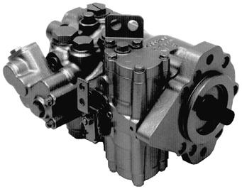
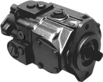
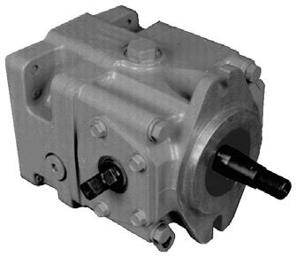
6 General description Series 40 family of pumps and motors Series 40 is a family of hydrostatic pumps and motors for medium power applications with maximum loads of 345 bar [5000 psi]. These pumps and motors can be applied together or combined with other products in a system to transfer and control hydraulic power. Series 40 pump + motor transmissions provide an infinitely variable speed range between zero and maximum in both forward and reverse modes of operation. The pumps and motors each come in four frame sizes: M25, M35, M44, and M46. Series 40 pumps are compact, high power density units. All models use the parallel axial piston / slipper concept in conjunction with a tiltable swashplate to vary the pump s displacement. Reversing the angle of the swashplate reverses the flow of fluid from the pump, reversing the direction of rotation of the motor output. Series 40 - M35, M44, and M46 pumps may include an integral charge pump to provide system replenish ing and cooling fluid flow, as well as servo control fluid flow on M46 pumps. M25 pumps are designed to receive charge flow from an auxiliary circuit or from a gear pump mounted on the auxiliary mounting pad. Series 40 pumps feature a range of auxiliary mounting pads to accept auxiliary hydraulic pumps for use in complementary hydraulic systems. Series 40 - M46 pumps offer proportional controls with either manual, hydraulic, or electronic actuation. An electric three-position control is also available. The M25, M35, and M44 pumps include a trunnion style direct displacement control. Series 40 motors also use the parallel axial piston / slipper design in conjunction with a fixed or tiltable swashplate. The family includes M25, M35, M44 fixed motor units and M35, M44, M46 variable motor units. For complete technical information on Series 40 motors, refer to Series 40 Motors, 520L0636. The M35 and M44 variable motors feature a trunnion style swashplate and direct displacement control. The M46 variable motors use a cradle swashplate design and a two-position hydraulic servo control. The M46 variable motor is available in a cartridge flange version, which is designed to be compatible with CW and CT compact planetary gearboxes. This combination provides a short final drive length for applications with space limitations. 6
7 General description Key features 4 sizes of variable displacement pumps 4 sizes of tandem pumps 3 sizes of variable displacement motors 3 sizes of fixed displacement motors Efficient axial piston design Complete family of control systems Proven reliability and performance Compact, lightweight Worldwide sales and service 7
8 General description M25 variable pump Auxiliary pad Trunnion Input shaft Valve plate Cylinder block Ball bearing Charge check and high pressure relief valve with bypass Charge relief valve Piston Swashplate P E M35 variable pump (M44 similar) Charge check and high pressure relief valve with bypass Charge relief valve Charge pump Valve plate Piston Ball bearing Auxiliary pad Trunnion Input shaft Cylinder block Swashplate P E M46 variable pump Charge check/ high pressure relie f va lv e Bypass va lv e Charge relie f va lv e Co ntro l Input shaf t Va lv e plat e Charge pum p Cy linder bloc k Cradl e swashplat e A uxilia ry pad Piston Ball bearin g P E 8
9 General description System circuit diagram Control handle Heat exchanger bypass Reservoir Filter Cylinder block assembly Displacement control valve Heat exchanger Charge relief valve Fixed displacement motor Cylinder block assembly Bypass valve Input shaft Variable displacement pump Check valves w/ high pressure relief valve Charge pump Loop flushing module Suction flow Charge pressure Servo pressure High pressure Case flow Output shaft P E A Series 40 - M46 variable pump is shown in a hydraulic circuit with a Series 40 - M35 fixed motor. The pump shown features manual displacement control. The circuit features suction filtration and heat exchanger. M46 Pump schematic diagram B N A E M3 M4 M5 A M1 L2 M2 B L1 S P E 9
10 Technical Specifications Overview Specifications and operating parameters are shown below. For additional information, see Operating parameters, page 13, System design parameters, page 16, Product coding, page 23, Features and options, page 25 and Control options, page 41. General Product line Series 40 Pumps Pump type In-line, axial piston, variable, positive displacement pumps Direction rotation Installation position Filtration configuration Other system requirements Clockwise (CW) or counterclockwise (CCW) available Discretionary, the housing must be filled with hydraulic fluid Suction or charge pressure filtration Independent braking system, suitable reservoir and heat exchanger Features Model Unit M25 PV M35 PV M44 PV M46 PV M25 PT M35 PT M44 PT M46 PT Type of mounting SAE B SAE B SAE B SAE B SAE B SAE B SAE B SAE B Port connections Twin Twin Twin Twin Twin Twin Twin Twin Integral charge cm 3 /rev pump (std) [in 3 /rev] [0.72] [0.72] [0.85] [1.00] [1.00] [1.40] Charge relief valve setting bar [psi] 14.0 [200] 14.0 [200] 14.0 [200] 19.5 [285] 14.0 [200] 14.0 [200] 14.0 [200] 19.5 [285] System pressure bar [psi] regulation [ ] Displacement limiters Option Option Input shaft option Splined, Tapered, or Straight Key Auxiliary mounting SAE A SAE A SAE A SAE A SAE A SAE A SAE A SAE A pad SAE B SAE B SAE B SAE B SAE B SAE B MDC, MDC, Control options DDC DDC DDC HDC, HDC, DDC DDC DDC EDC, EDC, FNR FNR Filtration Suction Filtration or Remote Charge Pressure Filtration configuration Specifications Model Unit M25 PV M35 PV M44 PV M46 PV M25 PT M35 PT M44 PT M46 PT Pump configuration Single variable pump Tandem variable pump Displacement cm 3 /rev [in 3 /rev] 24.6 [1.50] 35.0 [2.14] 43.5 [2.65] 46.0 [2.81] 24.6 x 2 [1.50 x 2] 35.0 x 2 [2.14 x 2] 43.5 x 2 [2.65 x 2] 46.0 x 2 [2.81 x 2] Weight kg [lb] 19 [41.5] 25 [55] 25 [55] 33 [73] 24 [56] 45 [99] 45 [99] 59 [131] Mass moment of inertia kg m 2 [slug ft 2 ] [0.0014] [0.0024] [0.0023] [0.0037] [0.0028] [0.0048] [0.0047] [0.0073] 10
11 Technical Specifications Operating parameters Model Unit M25 PV M35 PV M44 PV M46 PV M25 PT M35 PT M44 PT M46 PT Case pressure Continuous bar [psi] 1.7 [25] Maximum bar [psi] 5.2 [75] Speed limits max angle min -1 (rpm) max angle min -1 (rpm) Minimum min -1 (rpm) System pressure Continuous bar [psi] 210 [3000] Maximum bar [psi] 345 [5000] Theoretical max flow l/min at rated speed [US gal/min] [26.0] [33.4] [38.3] [48.6] [26.0] [33.4] [38.3] [48.6] (per pump) Inlet pressure bar absolute Continuous [in Hg vacuum] 0.8 [6.3] Maximum bar absolute [in Hg vacuum] 0.7 [9.2] Fluid specifications Parameter Unit Minimum Continuous Maximum Viscosity mm 2 /sec (cst) [SUS] [47] [70-278] [7500] Ratings and data are based Temperature C [ F] -40 [-40] 82 [180] 104 [220] on operation with premium Cleanliness ISO 4406 Class 18/13 or better petroleum-based hydraulic Filtration efficiency suction filtration β fluids containing oxidation, =75 (β ) charge filtration β rust, and foam inhibitors =75 (β 10 10) 11
12 Technical Specifications Performance The following performance graph provides typical volumetric and overall efficiencies for Series 40 pumps. These efficiencies apply for all Series 40 pumps. Pump performance as a function of operating speed 100 Efficienc y - % V o l u m e t r i c ef i f i c e n c y b a r [ p s i] V o l u m e t r i c ef f i c i e n c y b ar [ p si ] O v e r a l l ef f i c i e n c y ba r [5000 p s i ] O v e r 0 p s i ] a l l ef f i c i e n c y b a r [ Speed - % of rated speed T E The performance map provides typical pump overall efficiencies at various operating parameters. These efficiencies also apply for all Series 40 pumps. Pump performance as a function of operating speed and system pressure System pressure bar psi % 8 5 % 8 8 % 8 8 % 8 7 % 8 7 % 8 5 % 8 0 % Speed - % of rated speed T E 12
13 Operating parameters Fluids Ratings and performance data are based on operating with premium hydraulic fluids containing oxidation, rust, and foam inhibitors. These include premium turbine oils, API CD engine oils per SAE J183, M2C33F or G automatic transmission fluids (ATF), Dexron II (ATF) meeting Allison C-3 or Caterpillar T0 2 requirements, and certain specialty agricultural tractor fluids. For more information on hydraulic fluid selection, see Sauer- Danfoss publications: 520L0463, Hydraulic Fluids and Lubricants,, and 520L465, Experience with Biodegradable Hydraulic Fluids,. Viscosity Maintain fluid viscosity within the recommended range for maximum efficiency and bearing life. Minimum viscosity is acceptable only during brief occasions of maximum ambient temperature and severe duty cycle. Maximum viscosity is acceptable only at cold start: Limit speeds until the system warms up. See Sauer-Danfoss publications: 520L0463, Hydraulic Fluids and Lubricants, Fluid viscosity limits Condition mm 2 /s (cst) SUS Minimum 7 47 Continuous Maximum Temperature Maintain fluid temperature within the limits shown in the table. Minimum temperature relates to the physical properties of the component materials. Cold oil will not affect the durability of the motor components. However, it may affect the ability of the motor to transmit Temperature limits Minimum (intermittent, cold start) - 40 C [- 40 F] Continuous 82.2 C [180 F] Maximum C [220 F] power. Maximum temperature is based on material properties: Don t exceed it. Measure maximum temperature at the hottest point in the system. This is usually the case drain. Ensure fluid temperature and viscosity limits are concurrently satisfied. Charge pressure All systems require a charge (positive pressure) in the low side of the system loop for proper lubrication and rotating group operation. Maintain low loop (charge) pressure at a minimum of 6 bar [87 psi] above case pressure. For more information, refer to Charge Pump, page 25. Case pressure Maintain case pressure within the limits shown in the table. Ensure housing is filled with hydraulic fluid. Case pressure limits Maximum (continuous) Intermittent (cold start) 1.7 bar [25 psi] 5.2 bar [75 psi] C Caution Operating outside of charge and case pressure limits will damage the pump. To minimize this risk, use full size inlet and case drain plumbing, and limit line lengths. 13
14 Operating parameters Pressure ratings The table, Operating parameters, page 11, gives maximum and continuous pressure ratings for each displacement. Not all displacements operate under the same pressure limits. Definitions of the operating pressure limits appear below. System pressure is the differential pressure between system ports A and B. It is the dominant operating variable affecting hydraulic unit life. High system pressure, which results from high load, reduces expected life. Maintain system pressure at or below continuous working pressure during normal operation to achieve expected life. Continuous working pressure is the average, regularly occurring operating pressure. Operate at or below continuous working pressure for satisfactory product life. Maximum (peak) working pressure is the highest intermittent pressure allowed. Do not allow machine load to exceed maximum (peak) working pressure. All pressure limits are differential pressures referenced to low loop (charge) pressure. Subtract low loop pressure from gauge readings to compute the differential. System pressure limits Pressure Limits bar psi Continuous Maximum Speed ratings The table, Operating parameters, page 11, gives rated and maximum speeds for each displacement. Not all displacements operate under the same speed limits. Definitions of these speed limits appear below. Continuous speed is the maximum recommended operating speed at full power condition. Operating at or below this speed should yield satisfactory product life. Do not exceed maximum motor speed during unloaded, on-road travel over level ground. Maximum speed is the highest operating speed permitted. Exceeding maximum speed reduces pump life and can cause loss of hydrostatic power and braking capacity. Never exceed the maximum speed limit under any operating conditions. W Warning Unintended vehicle or machine movement hazard. The loss of hydrostatic drive line power, in any mode of operation (forward, neutral, or reverse) may cause the system to lose hydrostatic braking capacity. You must provide a braking system, redundant to the hydrostatic transmission, sufficient to stop and hold the vehicle or machine in the event of hydrostatic drive power loss. 14
15 Operating parameters Inlet pressure Achieving acceptable pump life and performance requires proper charge pump inlet design. A continuous inlet pressure of not less than 0.8 bar abs. (not more than 6.3 in. Hg vac.) is recommended. Normal pressure less than the minimum inlet pressure of 0.7 bar abs. (greater than 9.2 in. Hg vac.) indicates inadequate inlet design or a restricted filter. Pressures less than 0.7 bar abs. (greater than 9.2 in. Hg vac.) during cold start are possible, but should improve quickly as the fluid warms. Inlet pressure bar absolute in. Hg vacuum Continuous Minimum (max) Theoretical output The theoretical maximum flow at rated speed is a simple function of pump displacement and speed. This is a good gauge for sizing a companion motor. This does not take into account losses due to leakage or variations in displacement. Refer to Performance, page 12, for volumetric and overall efficiencies at various operating conditions. 15
16 System design parameters Sizing equations Use these equations to help choose the right pump size and displacement for your application. Based on SI units Based on US units Flow Output flow Q = V g n η v 1000 (l/min) Output flow Q = V g n η v 231 (US gal/min) Torque Input torque M = V g p 20 π η m (N m) Input torque M = V g p 2 π η m (lbf in) Power M n π Q p Input power P = = (kw) η t M n π Q p Input power P = = (hp) η t Variables SI units [US units] V g = Displacement per revolution cm 3 /rev [in 3 /rev] p O = Outlet pressure bar [psi] p i = Inlet pressure bar [psi] p = p O - p i (system pressure) bar [psi] n = Speed min -1 (rpm) η v = Volumetric efficiency η m = Mechanical efficiency η t = Overall efficiency (η v η m ) 16
17 System design parameters Filtration Ensure fluid entering pump is free of contaminants to prevent damage (including premature wear) to the system. Series 40 pumps require system filtration capable of maintaining fluid cleanliness at ISO class 22/18/13 or better. Consider these factors when selecting a system filter: Cleanliness specifications Contaminant ingression rates Flow capacity Desired maintenance interval Locate filter either on the inlet (suction filtration) or discharge (charge pressure filtration) side of the charge pump. Series 40 pumps are available with provisions for either strategy. Typically, a filter with a beta ratio of β 10 = 1.5 to 2.0 is adequate. However, open circuit systems supplied from a common reservoir may have considerably higher requirements. Because each system is unique, only a thorough testing and evaluation program can fully validate the filtration system. For more information, see Sauer-Danfoss publication 520L0467, Design Guidelines for Hydraulic Fluid Cleanliness. Suction filtration The suction filter is placed in the circuit between the reservoir and the inlet to the charge pump as shown in the accompanying illustration. Suction filtration To low pressure side of loop and servo control Strainer Reservoir Filter Charge relief valve To pump case Charge pump P E 17
18 System design parameters Filtration (continued) Charge filtration Provision for charge pressure filtration is available on all Series 40 pumps. The pressure filter is remotely mounted in the circuit after the charge pump, as shown in the accompanying illustra tion. Charge filtration Reservoir Strainer Filters used in charge pressure filtration circuits must be rated to at least 34.5 bar [500 psi] pressure. A µm screen located in the reservoir or in the charge inlet line is recommended when using charge pressure fil tration. A filter bypass valve is necessary to prevent filter damage and to avoid contaminants from being forced through the filter media by high pressure differentials across the filter. In the event of high pressure drop associated with a blocked filter or cold start-up conditions, fluid will bypass the filter. Avoid working with an open bypass for an extended period. We recommend a visual or electrical bypass indicator. Proper filter maintenance is mandatory. To Low Pressure side of loop and servo control To pump case Charge relief valve Filter with bypass Charge pump P E 18
19 System design parameters Redundant braking system requirement W Warning Unintended vehicle or machine movement hazard. The loss of hydrostatic drive line power, in any mode of operation (forward, neutral, or reverse) may cause the system to lose hydrostatic braking capacity. You must provide a braking system, redundant to the hydrostatic transmission, sufficient to stop and hold the vehicle or machine in the event of hydrostatic drive power loss. Loop flushing Closed circuit systems may require loop flushing to meet temperature and cleanliness requirements. A loop flushing valve removes hot fluid from the low pressure side of the system loop for additional cooling and filtering. Ensure the charge pump provides adequate flow for loop flushing and the loop flushing valve does not cause charge pressure to drop below recommended limits. Reservoir The reservoir provides clean fluid, dissipates heat, and removes entrained air from the hydraulic fluid. It allows for fluid volume changes associated with fluid expansion and cylinder differential volumes. Minimum reservoir capacity depends on the volume needed to perform these functions. Typically, a capacity of one half the charge pump flow (per minute) is satisfactory for a closed reservoir. Open circuit systems sharing a common reservoir require greater fluid capacity. Locate the reservoir outlet (suction line) near the bottom, allowing clearance for settling foreign particles. Use a µm screen covering the outlet port. Place the reservoir inlet (return lines) below the lowest expected fluid level, as far away from the outlet as possible. Use a baffle (or baffles) between the reser voir inlet and outlet ports to promote deaeration and reduce fluid surging. Case drain usage for tandem pumps On tandem pumps, excess flow from the charge relief valve is routed into the housing of the front pump. In order to ensure adequate case flushing, it is recommended that the rear housing drain ports be used as the case drain. M43/M44 tandem pumps with the option of opposing port endcaps do not follow the above rule. 19
20 System design parameters Bearing life and external shaft loading Bearing life is a function of speed, pressure and swashplate angle plus any external loads. Other life factors include oil type and viscosity. In vehicle propulsion drives with no external loads, where the speed, pressure, and swashplate angle are often changing, normal bearing B10 (90% survival) life will exceed the hydraulic unit life. In non-propel drives, such as conveyors or fan drives, the operating speed and pressure may be nearly constant leading to a distinctive duty cycle compared to that of a propulsion drive. In these types of applications, a bearing life review is recommended. Series 40 pumps are designed with bearings that can accept some incidental external radial and thrust loads. However, any amount of external load will reduce the expected bearing life. The allowable radial shaft loads are a function of the load position, the load orientation, and the operating pressures of the hydraulic unit. All external shaft loads have an effect on bearing life. In applications where external shaft loads cannot be avoided, the impact on bearing life can be mini mized by orienting the load to the 90 or 270 degree position. The maximum allowable radial loads (R e ), based on the maximum external moment (M e ) and the distance (L) from the mounting flange to the load, may be deter mined from the tables below and drawings on the next page. The maximum allowable radial load is calculated as: R e = M e / L Avoid thrust loads in either direction. If continuously applied external radial loads are 25% or more of the maximum allowable, or thrust loads are known to occur, contact your Sauer-Danfoss representative for an evaluation of unit bearing life. Optional high capacity bearings are available. Tapered output shafts or clamp-type couplings are recommended for applications where radial shaft side loads are present. Shaft loading parameters R e Maximum radial load M e Maximum external moment L Distance from mounting flange to point of load F e Force of cylinder block T e Thrust load Maximum external shaft moments M25 M35/44 M46 M e /N m [in lbf ] 101 [890] 121 [1075] 186 [1650] 20
21 System design parameters Bearing life and external shaft loading (continued) 180 External radial shaft load FB L F b 0 Re Re CCW CW Te 90 Re 270 Re 180 Re P E Direction of external shaft load 0 Re End view of shaf t 90 Re 270 Re Axis of swashplat e rotation 180 Re P E Hydraulic unit life Hydraulic unit life is defined as the life expectancy of the hydraulic components. It is a function of speed and system pressure; however, system pressure is the dominant operating variable. High pressure, which results from high load, reduces expected life. Design the hydraulic system to a projected machine duty cycle. Know the expected percentages of time at various loads and speeds. Ask your Sauer-Danfoss representative to calculate an appropriate pressure based your hydraulic system design. If duty cycle data is not available, input power and pump displacement are used to calculate system pressure. All pressure limits are differential pressures (referenced to charge pressure) and assume normal charge pressure. Series 40 pumps will meet satisfactory life expectancy if applied within the parameters specified in this bulletin. For more detailed information on hydraulic unit life see BLN-9884, Pressure and Speed Limits. 21
22 System design parameters Mounting flange loads Shock load moment is the result of an instantaneous jolt to the system. Continuous load moments are generated by the typical vibratory movement of the application. Avoid exces sive loading of the mounting flange such as adding tandem mounted auxiliary pumps and/or sub jecting pumps to high shock loads. Design pump applications to stay within the allowable shock load moment and allowable continuous load moment. Use the following formulas to estimate overhung load moment for multiple pump mountings: M S = G S (W 1 L 1 + W 2 L W n L n ) M C = G C (W 1 L 1 + W 2 L W n L n ) Refer to Installation drawings, page 52, to find pump length (L). Refer to the table Specifications, page 10, to find pump weight (W). An exact measure of W will depend on the pump s features. The tables below show allowable overhung load moment values. If system parameters exceed these values add additional pump support. Estimated maximum and continuous acceleration factors for some typical Series 40 applications are shown. Applications which experience extreme resonant vibrations may require additional pump support. Typical continuous (vibratory) values can vary significantly due to changes in engine and pump configuration and mounting methods. Overhung loading parameters M s Shock load moment M c Continuous load moment G s Maximum shock acceleration (Gs) G c Continuous (vibratory) acceleration (Gs) W n Weight of nth pump Distance from mounting flange to center of gravity L n of nth pump Allowable overhung parameters Continuous load Shock load moment Frame moment (M c ) (M s ) size N m [in lbf ] N m [in lbf ] M25 PV 361 [3200] 617 [5470] M25 PT 361 [3200] 559 [4950] M35 PV 517 [4600] 832 [7400] M35 PT 517 [4600] 754 [6700] M46 PV 517 [4600] 832 [7400] M46 PT 517 [4600] 754 [6700] Shaft loading parameters CG Pump 2 CG Pump 1 Mounting flange G-factors for sample applications Continuous Maximum (vibratory) (shock) Application acceleration acceleration (G c ) (G s ) Skid steer loader 4 10 Trencher 3 8 L2 L1 P E (rubber tires) Asphalt paver 2 6 Windrower 2 5 Aerial lift Turf care vehicle Vibratory roller 6 10 * Applications which experience extreme resonant vibrations require addition pump support. 22
23 Product coding Model code Series 40 variable pump Name plat e Model co de Model-No/Ident-N o. Model Co de LPV 025BACCAGAACA BFFDSFFFANNN Serial-N o L Model number Serial number Made in USA Place of manufacture Model code modules Displacement C D E F G H J M P V C B A A R A G N N Product Type K L M N P R S T A A A A A B A A B H A N N N C: Swashplate group D: Seal group E: Input shaft F: Rotation G: Charge pump displacement H: Charge pressure relief setting J: Filtration K: Displacement limiters L: Bypass valve M: System pressure protection N: Control P: Control handle position R: Control orifice diameters S: Auxiliary mounting pad T: Special hardware 23
24 Product coding Model code (continued) Series 40 tandem pump Name plat e Model co de Model-No/Ident-N o. Model Co de LPV 025BACCAGAACA BFFDSFFFANNN Serial-N o L Model number Serial number Made in USA Model code modules Place of manufacture Displacement E F G H J M P T C S R A E N N Product Type Front Pump C D K L M N P R B A A A B D D D L A F F Rear Pump Q D U X V Y Z W B C A A B D D D R A F F S T C N N N E: Input shaft F: Rotation G: Charge pump displacement H: Charge pressure relief setting J: Filtration C & Q: Swashplate D: Seal group K & U: Displacement L & X: Bypass valve M & V: System pressure protection N & Y: Control P & Z: Control handle position R & W: Control orifice S: Auxiliary mounting flange T: Special hardware Revised model code The model code is a modular description of a specific product and its options. To create an order code to include the specific options desired, see the Series 40 Pump Model Code Supplement or the Series 40 Price Book. 24
25 Features and options Charge pump Charge flow is required on all Series 40 units applied in closed circuit installations to make up for internal leak age, maintain positive pressure in the main circuit, provide flow for cooling, replace any leakage losses from external valving or auxiliary systems, and on M46 units, to provide flow and pressure for the control sys tem. Maintain rated charge pressure under all conditions of operation to prevent damage to the transmission. Charge pump in series 40 - M35 PV P E All Series 40 pumps (except M25 pumps) may be equipped with integral charge pumps. These charge pump sizes have been selected to meet the needs of a majority of Series 40 applications. Many factors influence the charge flow requirements and the resulting charge pump size selection. These factors include system pressure, pump speed, pump swashplate angle, type of fluid, temperature, size of heat exchanger, length and size of hydraulic lines, control response characteristics, auxiliary flow require ments, hydraulic motor type, etc. In most Series 40 applications a general guideline is that the charge pump dis placement should be equal to or greater than 10% of the total displacement of all units in the system. The total charge flow requirement is the sum of the charge flow requirements of each of the compo nents in the system. Use the information provided on the following pages to make a charge pump selection for a given application. 25
26 Features and options Charge pump (continued) System features and conditions that may invalidate the 10% of displacement rule include (but are not limited to): Operation at low input speeds (below 1500 RPM) Shock loading Excessively long system lines Auxiliary flow requirements Use of low speed high torque motors If a charge pump of sufficient dis placement to meet the 10% of displacement rule is not available or if any of the above conditions exist which could invalidate the 10% rule, contact your Sauer-Danfoss representative. A charge pump sizing worksheet is available in BLN-9885, Selection of Driveline Components. M25 pumps do not allow for integral charge pumps. Other Series 40 pumps are also available without charge pumps. When an integral charge pump is not used, an external charge supply is required to ensure adequate charge pressure and cooling. Charge pump output flow Flow at standard charge relief setting, 70 C [160 F] inlet l/min US Gal/min M46 PT M35 PT M46 PV M35 PV Speed min (rpm) T E Charge pump power requirements Power at standard charge relief setting, 70 C [160 F] inlet kw hp Speed min (rpm) T E M46PT M46PV M35PT M35PV 26
27 Features and options Charge relief valve An integral charge pressure relief valve provides a relief outlet for charge pressure. This valve, in effect, sets charge pressure. Flow through the valve is ported to case. The charge relief valve for the M25, M35, and M44 PV/PT is a flat poppet style valve. The M46 PV/PT uses a cone-style poppet valve. The nominal charge relief setting is referenced to case pressure. It is factory set at 1800 min -1 (rpm) with the pump in neutral position. A proper charge relief setting takes into account input speeds and control requirements. The charge pressure setting for pumps without an internal charge pump is set with an externally supplied charge flow of 19 l/min [5 US gal/min] on pumps and 38 l/min [10 US gal/min] on tandem pumps. These units must have adequate charge flow supplied to the charge inlet in order to maintain charge pressure at all times. Incorrect charge pressure settings may result in the inability to build required system pressure and/or inadequate loop flushing flows. Ensure correct charge pressure under all conditions of operation to maintain pump control performance. The charge relief valve is factory set. If necessary, it can be field adjusted with shims. Charge relief valve specs M25 M35 M44 M46 Type Flat poppet valve Cone poppet valve Available setting Adjustment bar [ psi] Via shims inside of valve cartridge* *Shimming offers adustment over a limited range, a spring change may be required to make a larger adjustment bar [ psi] Charge relief valve locations M25 PV Charge Relief Valve Charge Relief Valve M46 PV M35 & M44 PV P E 27
28 Features and options Check / high pressure relief valve Charge check and high pressure relief valves maintain circuit pressure in the proper range. The check valves allow charge flow to replenish the low pressure side of the working loop. The high pressure relief valves provide pressure protection to the high pressure side of the working loop. There are two cartridge style valves to handle each side of the working loop with flow in either direction. High pressure relief valves are available in a range of settings. You may specify individual port pressure settings. If high pressure relief valves are not desired, pumps may be equipped with charge circuit check valves only. C Caution High pressure relief valves are intended for transient overpressure protection and are not intended for continuous pressure control. Flow over relief valves for extended periods of time may result in severe heat build up. High flows over relief valves may result in pressure levels exceed ing the nominal valve setting and potential damage to system compo nents. Check/high relief valve specs Type Setting Option Cartridge-style poppet valve bar ( psi) Check only - no relief valve High pressure relief valve locations M25 PV Bypass valve High pressure/check valve High pressure relief valve M46 PV M35 & M44PV P E 28
29 Features and options Displacement limiters Series 40 - M46 PV or PT units are designed with optional mechanical displacement (stroke) limiters located in the servo piston. You can limit maximum displace ment of the pump to a certain per-cent of its maximum displacement to near zero in either direction. Displacement limits are fixed physical stops inside the pump and are not externally adjustable. It is possible to configure an M46 pump with an externally adjustable displacement limiter screw on one side only. The screw is located on the side of the servo piston opposite the neutral adjustment screw. W Warning Take care in adjusting displace ment limiters to avoid an undesirable condi tion of output flow or speed. Retorque the sealing lock nut after every adjustment to prevent an unexpected change in output conditions and to prevent external leakage during pump operation. One full revolution of the adjustment screw produces a change in displacement of approximately 4 cm 3 /rev [0.24 in 3 /rev]. Full unit dis placement is attained with the adjustment screw at its maximum extension from servo cover. All pumps are shipped with the limiter set for maximum pump displacement. An anti-tamper seal sleeve is provided. Series 40 - M25, M35, and M44 pumps do not have displacement limiters. M46 Displacement limiter Neutral adjustment screw Fixed displacement limiter Adjustable displacement limiter screw P E 29
30 Features and options Auxiliary mounting pads and auxiliary pumps Auxiliary mounting pads are available on all Series 40 pumps. A sealed cover is included as standard equipment on all mounting pads. An O-ring seals the auxiliary pump mounting flange to the pad. The drive coupling is lubricated with oil from the main pump case. Spline specifications and torque ratings are shown in the accompanying table. All auxiliary mounting pads meet SAE J744 specifications. Do not exceed the maxi mum pump input shaft rating shown in the Shaft availability and torque ratings table on page 33. Applications subject to severe vibratory or high G loading require an additional structural support. This is necessary to prevent leaks and possible mounting flange damage. Refer to Mounting flange loads, p. 22, for addi tional information. Auxiliary mounting pad specs Internal spline size 9T 16/32P 11T 16/32P 13T 16/32P Pad size SAE A SAE A SAE B Continuous: Max: Continuous: Max: Continuous: Max: Torque rating N m [in lbf ] [450] [950] 90 [800] 147 [1300] 124 [1100] 248 [2200] Availability M25 M35 M44 M46 The drawing and table below show the dimensions of the auxiliary pump mounting flanges and shafts. Auxiliary pump mounting flanges and shafts with the dimen sions noted are compatible with the auxiliary mounting pads on the Series 40 pumps. Auxiliary pump mating dimensions mm [in.] Pad size P B C D E F SAE A [32.50] [0.250] [0.500] [2.29] [0.59] [0.53] SAE B [4.000] [0.380] [0.60] [2.09] [0.69] [0.56] E max Mounting flange (ref ) D max F min spline engagement for full torque rating With undercut P Dia Without undercut B max C max 0.8 [0.03] max R Coupling 2.3 [0.090] recommended cutter clearance P E 30
31 Features and options Auxilliary mounting pads and auxiliary pumps (continued) Auxiliary mounting pads on Series 40 pumps M25 PV M35 & M44 PV A Pad M35 & M44 PV B Pad M35 & M44 PV M46 PV P E 31
32 Shaft options Shaft options Series 40 pumps are available with a variety of splined, straight keyed, and tapered shaft ends. Nominal shaft sizes and torque ratings are shown in the table on the next page. Torque ratings assume no external radial loading. Continuous torque ratings for splined shafts are based on splined tooth wear, and assume the mating spline has a minimum hardness of R c 55 and full spline depth with good lubrication. Maximum torque ratings are based on shaft torsional strength and assume a maximum of 200,000 load reversals. Recommended mating splines for Series 40 splined output shafts should be in accordance with ANSIB92.1 Class 5. Sauer-Danfoss external splines are modified Class 5 Fillet Root Side Fit. The external splined Major Diameter and Circular Tooth Thickness dimensions are reduced in order to assure a clearance fit with the mating spline. Other shaft options may exist. Contact your Sauer-Danfoss representative for availability. 32
33 Shaft options M25 variable pump Code Y Description Ø mm [0.874 in] Straight keyed Maximum torque rating N m [lbf in] Torque rating Continuous torque rating N m [lbf in] Drawing 140 [1240] 6.35 [0.250] Sq. key 38.1 [1.500] long 0.38 [0.015] min. R on edges Mounting flange (ref.) 7.9 [0.31] Coupling must not protrude beyond this surface 63.5 [2.50] 2.84 max. [0.112] dia. [0.874] P E A 13-tooth 16/32 pitch (ANSI B Class 5) 140 [1240] 85 [750] 7.9 [0.31] Mounting flange (ref.) Coupling must not protrude beyond this surface max [1.312] 16.5 [0.65] Full spline length 18.8 [0.74] max dia [0.855] dia [0.8125] Pitch dia 30 pressure angle 13 teeth, 16/32 pitch fillet root side fit per ANSI B92.1 class 5 also mates with flat root side fit P E C Ø 25.4 mm [1.000 in] 1:8 taper (SAE J501) 140 [1240] 2.84 [0.112] max [1.685] 6.35 [0.250] Sq. key [0.75] long 0.38 [0.015] min. R on edges 26.9 [1.06] 3/4-16 UNF-2B thd [0.969] max. Shaft dia. Mounting f lange (ref.) 33.3 [1.311] To gauge dim [0.875] Gauge dia [1.500] taper per foot per SAE J [1.000] nominal shaft dia. except for [0.969] dia as shown coupling must not protrude beyond [1.000] max. P E Other shaft options may exist. Contact your Sauer-Danfoss representative for availability and for specific installation drawings. Dimensions in mm [in] 33
34 Shaft options M25 tandem pump Code Y Description Ø mm [0.874 in] Straight keyed Maximum torque rating N m [lbf in] Torque rating Continuous torque rating N m [lbf in] Drawing 140 [1240] 6.35 [0.250] sq. key 38.1 [1.500] long 0.38 [0.015] min. R on edges Mounting flange (ref.) 7.9 [0.31] Coupling must not protrude beyond this surface 63.5 [2.50] 2.84 max. [0.112] dia. [0.874] P E A 13-tooth 16/32 pitch (ANSI B Class 5) 140 [1240] 85 [750] 7.9 [0.31] Mounting flange (ref.) 18.8 [0.74] max. dia. Coupling must not protrude beyond this surface max. [1.312] 16.5 [0.65] full spline length [0.588] dia [0.8125] pitch dia. 30 pressure angle 13 teeth, 16/32 pitch fillet root side fit. per ANSI B92.1 class 5 also mates with flat root side fit. P E C Ø 25.4 mm [1.000 in] 1:8 taper (SAE J501) 140 [1240] 2.84 [0.112] max [1.685] 6.35 [0.250] Sq. key [0.75] long 0.38 [0.015] min. R on edges 26.9 [1.06] 3/4-16 UNF-2B thd [0.969] max. Shaft dia. Mounting f lange (ref.) 33.3 [1.311] To gauge dim [0.875] Gauge dia [1.500] taper per foot per SAE J [1.000] nominal shaft dia. except for [0.969] dia as shown coupling must not protrude beyond [1.000] max. P E Other shaft options may exist. Contact your Sauer-Danfoss representative for availability and for specific installation drawings. Dimensions in mm [in] 34
35 Shaft options M35/44 variable pump Code Y Description Ø mm [0.874 in] Straight keyed Maximum torque rating N m [lbf in] Torque rating Continuous torque rating N m [lbf in] 226 [2000] Drawing 6.35 [0.250] sq. key 38.1 [1.500] long 0.38 [0.015] min. R on edges Mounting flange (ref.) 2.85 [0.112] max [0.874] dia. 7.9 [0.31] Coupling must not protrude beyond this surface 63.5 [2.50] P E A 13-tooth 16/32 pitch (ANSI B Class 5) 126 [2000] 124 [1100] 7.9 [0.31] Mounting flange (ref) Coupling must not protrude beyond this surface 33.3 [1.31] U V T G 15-tooth 16/32 pitch (ANSI B Class 5) 362 [3200] 153 [1350] W dia pitch Y teeth, 16/32 30 pressure angle fillet root side fit per ANSI B class 5 Also mates with flat root side fit P E Shaft option Shaft dia. Full spline Major dia. Pitch dia. No. teeth T U V W Y G [0.865] 18.5 [0.73] [ [0.9375] 15 A 18.8 [.074] [0.855] [0.8125] 13 N Ø 25.4 mm [1.000 in] 1:8 taper (SAE J501) 497 [4400] 42.8 [1.685] 6.35 [0.250] Sq. key [0.75] long 0.38 [0.015] min. R on edges Mounting flange (ref.) 3/4-16 UNF-2B thd [0.112] max [0.875] Gauge dia in/ft per SAE standard J [1.000] Nom shaft dia. Coupling must not protrude beyond 25.4 [1.000] max [1.06] 33.3 [1.311] Gauge dim. P E Other shaft options may exist. Contact your Sauer-Danfoss representative for availability and for specific installation drawings. Dimensions in mm [in] 35
36 Shaft options M35/44 tandem pump Code Y Description Ø mm [0.874 in] Straight keyed Maximum torque rating N m [lbf in] Torque rating Continuous torque rating N m [lbf in] 226 [2000] Drawing 6.35 [0.250] sq. key 38.1 [1.500] long 0.38 [0.015] min. R on edges Mounting flange (ref.) 2.85 [0.112] max [0.874] dia. 7.9 [0.31] Coupling must not protrude beyond this surface 63.5 [2.50] P E A 15-tooth 16/32 pitch (ANSI B Class 5) 362 [3200] 153 [1350] 7.9 [0.31] Mounting flange (ref.) Coupling must not protrude beyond this surface [1.31] [0.053] U V T 48.9 [1.925] G 15-tooth 16/32 pitch (ANSI B Class 5) 362 [3200] 153 [1350] W dia pitch Y teeth, 16/32 30 pressure angle fillet root side fit per ANSI B class 5 Also mates with flat root side fit Option A U [1.300] Option G V T P E Shaft option Shaft dia. Full spline Major dia. Pitch dia. No. teeth T U V W Y G [0.865] 39.4 [1.55] [0.9800] [0.9375] 15 A [0.865] 18.5 [0.73] [0.9800] [0.9375] 15 N Ø 25.4 mm [1.000 in] 1:8 taper (SAE J501) 497 [4400] 2.84 [0.112] max [1.685] 6.35 [0.250] Sq. key [0.75] long 0.38 [0.015] min. R on edges 26.9 [1.06] 3/4-16 UNF-2B thd [0.969] max. Shaft dia. Mounting f lange (ref.) 33.3 [1.311] To gauge dim [0.875] Gauge dia [1.500] taper per foot per SAE J [1.000] nominal shaft dia. except for [0.969] dia as shown coupling must not protrude beyond [1.000] max. P E Other shaft options may exist. Contact your Sauer-Danfoss representative for availability and for specific installation drawings. Dimensions in mm [in] 36
37 Shaft options M46 variable pump Code V W Description Ø mm [0.999 in] Straight keyed Maximum torque rating N m [lbf in] Torque rating Continuous torque rating N m [lbf in] 362 [3200] Drawing 6.35 [0.250] Sq key 44.4 [1.75] long 0.38 [0.015] min R on edges 2.85 [0.112] max Mounting flange (ref) 25.4 [1.00] dia 7.4 [0.29] Coupling must not protrude beyond this surface 69.6 [2.74] P E N P R S Ø 25.4 mm [1.000 in] 1:8 taper (SAE J501) 497 [4400] Mounting flange (ref.) Coupling must not protrude beyond 36.3 [1.44] max [1.67] 6.35 [0.250] Sq. key [0.75] long 0.38 [0.015] min. R on edges 3/4-16 UNF-2B thd [0.112] max [0.875] gauge dia [1.06] Hex nut (option) torque nut to 149 to 190 Nm [110 to 140 Lbf.ft.] Thds to be cleaned and lubricated 26.9 [1.06] 12.7 [0.50] 1.50 taper per foot SAE standard J [1.000] nominal shaf t dia [1.311] Gauge Dim. P E Other shaft options may exist. Contact your Sauer-Danfoss representative for availability and for specific installation drawings. Dimensions in mm [in] 37
38 Shaft options M46 variable pump Torque rating Code Description Maximum torque rating N m [lbf in] Continuous torque rating N m [lbf in] Drawing G H J K A B D E X Z 13-tooth 16/32 pitch (ANSI B Class 5) 15-tooth 16/32 pitch (ANSI B Class 5) 226 [2000] 124 [1100] 362 [3200] 153 [1350] 7.4 [0.29] Mounting flange (ref.) Coupling must not protrude beyond this surface S U V T W pitch dia Y teeth,16/32 pitch 30 pressure angle fillet root side fit per ANSI B class 5 also mates with flat root side fit P E Shaft option Length Shaft dia. Full spline Major dia. Pitch dia. No. teeth S T U V W Y G, H, J [0.88] 23.4 [0.92] & K [1.485] [0.9800] [0.9375] A, B & D [0.80] [0.64] [1.297] [0.8550] [0.8125] E, & X, [0.88] [1.57] [2.155] [0.9800] [0.9375] Z [0.88] [1.45] [2.040 [0.9800] [0.9375] Other shaft options may exist. Contact your Sauer-Danfoss representative for availability and for specific installation drawings. Dimensions in mm [in] 38
39 Shaft options M46 tandem pump Code J Description Ø mm [0.999 in] Straight keyed Maximum torque rating N m [lbf in] Torque rating Continuous torque rating N m [lbf in] 362 [3200] Drawing 6.35 [0.250] sq. key [1.75] long 0.38 [0.015] min. R on edges Mounting flange (ref.) [0.999] dia [0.294] Coupling must not protrude beyond this surface [2.735] P E C Ø 25.4 mm [1.000 in] 1:8 taper (SAE J501) 497 [4400] 42.8 [1.685] 6.35 [0.250] Sq. key [0.75] long 0.38 [0.015] min. R on edges Mounting flange (ref.) UNF-2thd [0.112] max [0.875] Gauge dia. Coupling must not protrude beyond 25.4 [1.000] max [1.06] 33.3 [1.311] gauge dim 1.50 taper per foot per SAE standard J [1.000] Nominal shaft dia. P E Other shaft options may exist. Contact your Sauer-Danfoss representative for availability and for specific installation drawings. Dimensions in mm [in] 39
Series 40 Direct Displacement Pumps
 Technical Information powersolutions.danfoss.com Revision history Table of revisions Date Changed Rev July 2017 Removed outdated images 0703 January 2017 Minor updates 0702 July 2015 Minor edits 0701 February
Series 40 Direct Displacement Pumps. Technical Information
 Series 40 Direct Displacement Pumps Technical Information Revisions History of Revisions Table of Revisions Date Page Changed Rev. September 2013 5, 11 change system pressure specs FB August 2013 all Remove
Series 40 Axial Piston Motors
 Technical Information powersolutions.danfoss.com Revision history Table of revisions Date Changed Rev February 2017 Corrected document formatting 0703 October 2016 Minor updates 0702 January 2014 Danfoss
Series 40 Axial Piston Motors. Technical Information
 Series 40 Axial Piston Motors Technical Information Revisions Revisions Table of Revisions Date Page Changed Rev. November 2007 31 correction to maximum torque rating 15 and 19 tooth FB April 2007 29 Revised
Series 42 4T Axial Piston Tandem Pumps
 Technical Information Series 42 4T Axial Piston Tandem Pumps powersolutions.danfoss.com Revision history Table of revisions Date Changed Rev June 2016 converted to new layout 0101 May 2015 Converted to
Axial Piston Pumps Series 40 M46
 Technical Information Axial Piston Pumps Series 40 M46 powersolutions.danfoss.com Revision history Table of revisions Date Changed Rev March 2017 Minor updates - FNR Control options 0209 October 2016 Minor
Series 42 Axial Piston Pumps. Technical Information
 Series 42 Axial Piston Pumps Technical Information Revisions History of Revisions Table of Revisions Date Page Changed Rev. October 2009 59 Connector/Spool: 6=MS, high gain spool CC October 2009 8, 11
Series 90 Axial Piston Motors. Technical Information
 Series 90 Axial Piston Motors Technical Information HISTORY OF REVISIONS Table of Revisions Date Page Changed Rev. Fourth edition 2 520L0604 Contents GENERAL DESCRIPTION Cross section Cross section Cross
Series 20 Axial Piston Pumps. Technical Information
 Series 20 Axial Piston Pumps Technical Information General Description INTRODUCTION Sauer-Danfoss a world leader in hydraulic power systems has developed a family of axial piston pumps. DESCRIPTION Sauer-Danfoss
Series 20 Axial Piston Pumps. Technical Information
 Series 20 Axial Piston Pumps Technical Information General Description INTRODUCTION Sauer-Danfoss a world leader in hydraulic power systems has developed a family of axial piston pumps. DESCRIPTION Sauer-Danfoss
Series 42 Closed Circuit Axial Piston Pumps
 Technical Information Series 42 Closed Circuit Axial Piston Pumps www.danfoss.com Revision history Table of revisions Date Changed Rev August 2018 Minor Update 0103 December 2016 Minor Update 0102 June
Series 45 Open Circuit Axial Piston Pumps. Technical Information. Displacement Piston. Swashplate. Piston. Tapered Roller Bearing
 Series 45 Open Circuit Axial Piston Pumps Technical Information Displacement Piston Piston Swashplate Tapered Roller earing Tapered Roller earing Valve Plate Cylinder lock Kit Shaft Seal General Description
L and K Frame Variable Motors. Technical Information
 L and K Frame Variable Motors Technical Information Revisions Revisions Table of Revisions Date Page Changed Rev. April 2008 6 corrected the schematic drawings BE January 2008 17 removed displacement limiter
4T Axial Piston Pumps. Technical Information
 4T Axial Piston Pumps Technical Information Using this manual ORGANIZATION AND HEADINGS To help you quickly find information in this manual, the material is divided into sections, topics, subtopics, and
Series 90. Axial Piston Motors Technical Information
 Series 90 Axial Piston Motors Technical Information Series 90 Family of Pumps and Motors Series 90 hydrostatic pumps and motors can be applied together or combined with other products in a system to transfer
Series 90 Axial Piston Pumps. Technical Information
 Series 90 Axial Piston Pumps Technical Information Revisions History of Revisions Table of Revisions Date Page Changed Rev. March 2010 Various Fix O-ring dimensions in dimension drawings FE December 2009
Series 40 Axial Piston Motors Technical Information
 Series 40 Axial Piston Motors Technical Information Series 40 Family of Pumps and Motors Series 40 is a family of hydrostatic pumps and motors for "medium power" applications with maximum loads of 345
Axial Piston Pumps Series 40
 Series 40 Family of Pumps and Motors Series 40 is a family of hydrostatic pumps and motors for "medium power" applications with maximum loads of 345 bar (0 psi). These pumps and motors can be applied together
Series TMM Axial Piston Motor. Technical Information
 Series TMM Axial Piston Motor Technical Information General Description GENERAL DESCRIPTION These motors are designed primarily to be combined with other products in closed circuit systems to transfer
Technical Information Series 45 G Frame powersolutions.danfoss.com
 MAKING MODERN LIVING POSSIBLE Technical Information Series 45 G Frame powersolutions.danfoss.com Contents Frame G Design... 4 Specifications... 5 Performance G74B... 6 Performance G9C... 7 Order code...
Series 45 Frame J Axial Piston Open Circuit Pumps. Technical Information
 Series 45 Frame J Axial Piston Open Circuit Pumps Technical Information Using this manual ORGANIZATION AND HEADINGS To help you quickly find information in this manual, the material is divided into sections,
Series 90 Axial Piston Pumps. Technical Information
 Series 90 Axial Piston Pumps Technical Information Using this manual ORGANIZATION AND HEADINGS To help you quickly find information in this manual, the material is divided into sections, topics, subtopics,
Series 45 Axial Piston Open Circuit Pumps. Technical Information
 Series 45 Axial Piston Open Circuit Pumps Technical Information Revisions History of Revisions Table of Revisions Date Page Changed Rev. September 28 58-62 dimension changes for Frame J FJ June 28 78,
PM50 VARIABLE DISPLACEMENT PUMP CLOSED LOOP CIRCUIT T E C H N I C A L C A T A L O G
 PM50 VARIABLE DISPLACEMENT PUMP CLOSED LOOP CIRCUIT T E C H N I C A L C A T A L O G PM50 - Variable displacement pump POCLAIN HYDRAULICS OVERVIEW PM50 is a variable displacement, axial piston pump, with
Series 90 Axial Piston Pumps. Technical Information
 Series 90 Axial Piston Pumps Technical Information Revisions History of Revisions Table of Revisions Date Page Changed Rev. July 2011 35 Typo, 45cc should be 42cc GB July 2011 all Major update GA August
P90 VARIABLE DISPLACEMENT PUMP T E C H N I C A L C A T A L O G
 P90 VARIABLE DISPLACEMENT PUMP T E C H N I C A L C A T A L O G Variable displacement pump POCLAIN HYDRAULICS Design Slider block Swashplate hold-down Servo piston Servo arm Piston Slipper Displacement
H1 Axial Piston Pump Size 147/165, Single. Technical Information
 H1 Axial Piston Pump Size 147/165, Single Technical Information Revisions Revision History Table of revisions Date Page Changed Rev 30 Jul, 2009 First edition AA Jul, 2010 4-6, 10, 12-13 New EC directive
LPV Axial Piston Closed Circuit Pumps. Technical Information
 LPV Axial Piston Closed Circuit Pumps Technical Information Revisions History of Revisions Table of Revisions Date Page Changed Rev. October 2008 6 added serial number plate drawing AE April 2008 29 changes
shhark continuum PUMPS Group 1 l Technical Information
 shhark continuum PUMPS Group 1 l Technical Information 66M 88Y 55K 77C 33M 50C 100Y 66M 88Y 2 GROUP 1 shhark continuum PUMPS I TECHNICAL INFORMATION History of revisions Date Page Changed Rev. May 2016
H1 Axial Piston Tandem Pumps Size 045/053
 MAKING MODERN LIVING POSSIBLE Technical Information H1 Axial Piston Tandem Pumps Size 045/053 powersolutions.danfoss.com Revision history Table of revisions Date Changed Rev November 2015 Master Model
Series 20 Axial Piston Motors. Technical Information
 Series 20 xial Piston Motors Technical Information General Description INTRODUCTION Sauer-Danfoss a world leader in hydraulic power systems has developed a family of axial piston motors. DESCRIPTION Sauer-Danfoss
H1 Axial Piston Pump Size 115/130, Single. Technical Information
 H1 Axial Piston Pump Size 115/130, Single Technical Information Revisions Revision History Table of revisions Date Page Changed Rev 30 Jul, 2009 First edition AA Jun, 2010 4-6, 12, 14, New EC directive
H1 Axial Piston Pump Size 045/053, Single. Technical Information
 H1 Axial Piston Pump Size 045/053, Single Technical Information Revisions Revision History Table of revisions Date Page Changed Rev 30 Jul, 2009 First edition AA Feb 2010 various 14 teeth added BA Jun,
Series 90 Axial Piston Pumps
 MAKING MODERN LIVING POSSIBLE Series 90 Axial Piston Pumps powersolutions.danfoss.com Revision History Table of Revisions Date Changed Rev March 2014 corrections to pin assignments - page 48 FB February
Series 20 Axial Piston Motors. Technical Information
 Series 20 xial Piston Motors Technical Information General Description INTRODUCTION Sauer-Danfoss a world leader in hydraulic power systems has developed a family of axial piston motors. DESCRIPTION Sauer-Danfoss
PMV0 VARIABLE DISPLACEMENT PUMP CLOSED LOOP CIRCUIT T E C H N I C A L C A T A L O G
 PMV0 VARIABLE DISPLACEMENT PUMP CLOSED LOOP CIRCUIT T E C H N I C A L C A T A L O G PMV0 - Variable displacement pump POCLAIN HYDRAULICS OVERVIEW PMV0 is a variable displacement, axial piston pump, with
Axial Piston Pumps LPV
 Technical Information Axial Piston Pumps LPV powersolutions.danfoss.com Revision history Table of revisions Date Changed Rev September 2017 update model code 0102 July 2015 Danfoss Layout 0100 January
Distribuíção, revenda emanutenção. CatálogosOnline. (11) (11)
 (11)") Distribuíção, revenda emanutenção CatálogosOnline (11)4174-3300-(11)4765-6775 www.hmc.com.br MAKING MODERN LIVING POSSIBLE Technical Information Axial Piston Pumps Series 20 powersolutions.danfoss.com
Distribuíção, revenda emanutenção CatálogosOnline (11)4174-3300-(11)4765-6775 www.hmc.com.br MAKING MODERN LIVING POSSIBLE Technical Information Axial Piston Pumps Series 20 powersolutions.danfoss.com
Group 1 Gear Pumps Technical Information General Information
 General Information OVERVIEW The Sauer-Danfoss Group is a range of peak performance fixed-displacement gear pumps. Constructed of a high-strength extruded aluminum body with aluminum cover and flange,
P90 VARIABLE DISPLACEMENT PUMP T E C H N I C A L C A T A L O G
 P90 VARIABLE DISPLACEMENT PUMP T E C H N I C A L C A T A L O G Variable displacement pump POCLAIN HYDRAULICS Design Piston Slipper Slider block Servo piston Servo arm Displacement control Feedback linkage
DDC20 Axial Piston Variable Displacement Pump
 Technical Information DDC20 Axial Piston Variable Displacement Pump powersolutions.danfoss.com Revision history Table of revisions Date Changed Rev February 2017 Change charge pump housing 0102 January
Vane Pumps. VMQ Series Vane Pumps For Industrial and Mobile Applications Displacements to 215 cm 3/ r (13.12 in 3 /r) Pressures to 260 bar (3800 psi)
 Pressures to 260 bar (3800 psi)") Vickers Vane Pumps VMQ Series Vane Pumps For Industrial and Mobile Applications Displacements to 215 cm 3/ r (13.12 in 3 /r) Pressures to 260 bar (3800 psi) 5008.00/EN/0596/A A.25 Introduction From the
Vickers Vane Pumps VMQ Series Vane Pumps For Industrial and Mobile Applications Displacements to 215 cm 3/ r (13.12 in 3 /r) Pressures to 260 bar (3800 psi) 5008.00/EN/0596/A A.25 Introduction From the
Group 1. Gear Pumps Technical Information
 Group Gear Pumps Technical Information Group Family of Gear Pumps SAUER-SUNDSTRAND High performance gear pumps are fixed displacement pumps which consist of the pump housing, drive gear, driven gear, DU
Vickers. Vane Pumps. Double Thru-drive Vane Pumps. High speed, high pressure VQT Series for mobile equipment. Released 7/93
 Vickers Vane Pumps Double Thru-drive Vane Pumps High speed, high pressure VQT Series for mobile equipment Released 7/93 612 Introduction Double VQT high performance pumps are fixed displacement units that
T1P Transit Mixer Axial Piston Pump Size 069/089
 Technical Information T1P Transit Mixer Axial Piston Pump Size 069/089 powersolutions.danfoss.com Revision history Table of revisions Date Changed Rev May 2016 Updated to Engineering Tomorrow design. 0201
H1 Axial Piston Tandem Pumps Size 045/053/060/068
 Technical Information H1 Axial Piston Tandem Pumps Size 045/053/060/068 powersolutions.danfoss.com Revision history Table of revisions Date Changed Rev September 2017 add G6 option 0603 June 2017 minor
MP1 Axial Piston Pumps Size 28/32, 38/45
 Technical Information MP1 Axial Piston Pumps Size 28/32, 38/45 www.danfoss.com Revision history Table of revisions Date Changed Rev May 2018 add 14 tooth shaft, minor edits 0106 March 2018 update MDC control
Series T90 Transit Mixer Drive System
 MAKING MODERN LIVING POSSIBLE Technical Information Series T90 Transit Mixer Drive System powersolutions.danfoss.com Contents Series T90 Transit Mixer Drive Transit Mixer Pump Series T90 General Description...
MP1 Axial Piston Pumps Size 28/32, 38/45
 Technical Information MP1 Axial Piston Pumps Size 28/32, 38/45 powersolutions.danfoss.com Revision history Table of revisions Date Changed Rev August 2016 First Edition 0101 2 Danfoss August 2016 BC00000352en-US
Medium Duty Piston Pump Variable Displacement Closed Circuit
 Medium Duty Piston Pump Variable Displacement Closed Circuit Model 70160 Model 70360 Model 72400 20.3 cm 3 /r [1.24 in 3 /r] 40.6 cm 3 /r [2.48 in 3 /r] 40.6 cm 3 /r [2.48 in 3 /r] 23.6 cm 3 /r [1.44 in
H1 Bent Axis Variable Displacement Motors Frame Size 080 Frame Size 110. Technical Information
 H1 Bent Axis Variable Displacement Motors Frame Size 080 Frame Size 110 Technical Information Revisions History of Revisions Table of revisions Date Page Changed Rev. 1 Dec, 2008 Different pages New frame
CAST IRON GEAR PUMPS AND MOTORS Cascade Group 3 l Technical Information
 CAST IRON GEAR PUMPS AND MOTORS Cascade Group 3 l Technical Information 2 CASCADE GROUP 3 I TECHNICAL INFORMATION History of revisions Date Page Changed Rev. March 2015 - First edition - September 2016
H1 Axial Piston Pump Size 147/165, Single
 MAKING MODERN LIVING POSSIBLE Technical Information H1 Axial Piston Pump Size 147/165, Single powersolutions.danfoss.com Revision History Table of Revisions Date Changed Rev Mar 2014 Converted to Danfoss
TPV Variable Displacement Closed Loop System Axial Piston Pump THE PRODUCTION LINE OF HANSA-TMP HT 16 / M / 851 / 0813 / E
 HYDRAULIC COMPONENTS HYDROSTATIC TRANSMISSIONS GEARBOXES - ACCESSORIES THE PRODUCTION LINE OF HANSA-TMP Variable Displacement Closed Loop System CONTENTS General Information... Order Code... Manual Control
H1T 045/053/060/068 H1 Axial Piston Tandem Pumps
 Technical Information H1T 045/053/060/068 H1 Axial Piston Tandem Pumps www.danfoss.com Revision history Table of revisions Date Changed Rev July 2018 Major revision. 0801 June 2018 Angle sensor chapters
H1 Axial Piston Single Pumps Size 147/165
 MAKING MODERN LIVING POSSIBLE Technical Information H1 Axial Piston Single Pumps Size 147/165 powersolutions.danfoss.com Revision history Table of revisions Date Changed Rev September 2014 MDC, CCO, and
Series 45 Axial Piston Open Circuit Pumps Technical Information Frame F
 Design cross section LS contro l (attached to endcap) LS spoo l LS adjustmen t PC spoo l PC adjustmen t Servo piston Bias sprin g Piston Slipper Tapered roller bearing Valve plate Shaft seal Cylinder block
L and K Frame Variable Motors
 Technical Information powersolutions.danfoss.com Revision history Table of revisions Date Changed Rev April 2018 Model code minimum angle update 0204 November 2016 Minor updates 0203 June 2015 new cartridge
Transit Mixer Axial Piston Motor Size 070/084/089
 Technical Information Transit Mixer Axial Piston Motor Size 070/084/089 powersolutions.danfoss.com Revision history Table of revisions Date Changed Rev June 2017 Update to Engineering Tomorrow 0202 Mar
Solutions. We Manufacture. H y d r a u l i c s. Eaton Medium Duty Piston Pump. h y d r a u l i c s
 H y d r a u l i c s ydraulics Eaton Medium Duty Piston Pump h y d r a u l i c s Model 70122, 70422, 70423, and 70523 or -Flow Compensated Piston Pumps We Manufacture April 1997 Solutions S o l u t i o
GEAR PUMPS Group 3 l Technical Information
 GEAR PUMPS Group 3 l Technical Information 2 GROUP 3 GEAR PUMPS I TECHNICAL INFORMATION History of revisions Date Page Changed Rev. 28, June 2010 - First edition A 24, Feb 2011 1,2,11,32 Covers to blue
GEAR PUMPS Group 4 l Technical Information
 GEAR PUMPS Group 4 l Technical Information 2 GROUP 4 GEAR PUMPS I TECHNICAL INFORMATION History of revisions Date Page Changed Rev. 28, June 2010 - First edition A 30, Sept 2013 ALL Layout and options
Group 1 Gear Pumps. Technical Information. OpenCircuitGear MEMBER OF THE SAUER-DANFOSS GROUP
 Group Gear Pumps OpenCircuitGear Technical Information General Information History of revisions Table of revisions Date Page Changed Rev., June - First edition A, Feb,,, Covers to blue color, TurollaOCG
Group 3 Gear Pumps. Technical Information. OpenCircuitGear MEMBER OF THE SAUER-DANFOSS GROUP
 Group 3 Gear Pumps OpenCircuitGear Technical Information General Information History of revisions Table of revisions Date Page Changed Rev. 28, June 21 - First edition A 24, Feb 211 1,2,11, 32 Covers to
LDU20 Closed Circuit Axial Piston Transmission
 Technical Information LDU20 Closed Circuit Axial Piston Transmission powersolutions.danfoss.com Revision history Table of revisions Date Changed Rev April 2018 minor change 0102 June 2016 Converted to
Catalog HY /NA. Catalog HY /NA. Parker Hannifin Corporation Hydraulic Pump Division Marysville, Ohio USA
 Catalog HY28-6/NA PV, PVT Series Piston Pumps Variable Volume Catalog HY28-6/NA 1 Catalog HY28-6/NA Notes Series PV 2 Catalog HY28-6/NA Introduction Series PV Quick Reference Data Chart Pump Delivery Approx.
Section 5: Hydraulic Pump SAUER DANFOSS. SERVICE MANUAL Property of American Airlines. 5-5 Page 1 September 09 HYDRAULIC PUMP
 Section 5: Hydraulic Pump SAUER DANFOSS SERVICE MANUAL HYDRAULIC PUMP 5-5 Page 1 September 09 THIS PAGE INTENTIONALLY LEFT BLANK Series 45 Frame G and H Open Circuit Axial Piston Pumps Service Manual Introduction
PM45 VARIABLE DISPLACEMENT PUMP CLOSED LOOP CIRCUIT T E C H N I C A L C A T A L O G
 PM45 VRILE DISPLCEMENT PUMP CLOSED LOOP CIRCUIT T E C H N I C L C T L O G PM45 - Variable displacement pump POCLIN HYDRULICS OVERVIEW PM45 is a variable displacement, axial piston pump, with swashplate
Disc Valve Hydraulic Motors 2000 Series
 Disc Valve Hydraulic Motors 10.2014 inspired hydraulics. Änderungen und Druckfehler vorbehalten 10.2014 EN EATON_Motoren english Highlights Port A Features Three zone design for longer life and true bi-directionality.
Axial Piston Fixed Motor A2FM
 Axial Piston Fixed Motor A2FM RE 91001/06.2012 1/46 Replaces: 09.07 Data sheet Series 6 Size Nominal pressure/maximum pressure 5 315/350 bar 10 to 200 400/450 bar 250 to 1000 350/400 bar Open and closed
PM25 VARIABLE DISPLACEMENT PUMP CLOSED LOOP CIRCUIT T E C H N I C A L C A T A L O G
 PM25 VRILE DISPLCEMENT PUMP CLOSED LOOP CIRCUIT T E C H N I C L C T L O G PM25 - Variable displacement pump POCLIN HYDRULICS OVERVIEW PM25 is a variable displacement, axial piston pump, with swashplate
PM25 VARIABLE DISPLACEMENT PUMP CLOSED LOOP CIRCUIT T E C H N I C A L C A T A L O G
 PM25 VRILE DISPLCEMENT PUMP CLOSED LOOP CIRCUIT T E C H N I C L C T L O G PM25 - Variable displacement pump POCLIN HYDRULICS OVERVIEW PM25 is a variable displacement, axial piston pump, with swashplate
Technical Information Axial Piston Motors Series 20 powersolutions.danfoss.com
 MKING MODERN LIVING POSSILE Technical Information xial Piston Motors Series 20 powersolutions.danfoss.com General Information Introduction Danfoss a world leader in hydraulic power systems has developed
Series PVP Variable Volume Piston Pumps
 Series PVP Variable Volume Piston Pumps Catalog HY28-2661-CD/US zp2 hpm12-1.p65, lw, jk 1 Notes Series PVP hpm12-1.p65, lw, jk 2 Introduction Series PVP Series Sizes 6-14 Phased Out For Reference Only
D1 High Power Open Circuit Pumps Size 130/145/193/260
 Technical Information D1 High Power Open Circuit Pumps Size 130/145/193/260 Available only for APAC / EU regions powersolutions.danfoss.com Revision history Table of revisions Date Changed Rev January
Disc Valve Hydraulic Motors 4000 Compact Series
 Disc Valve Hydraulic Motors 10.2014 inspired hydraulics. Änderungen und Druckfehler vorbehalten 10.2014 EN EATON_Motoren english Port B Port A Features Shuttle Valve with Back- Pressure Relief Valve Highlights
Gear Motors Group 1, 2 and 3. Technical Information. OpenCircuitGear MEMBER OF THE SAUER-DANFOSS GROUP
 Gear Motors Group 1, 2 and 3 OpenCircuitGear Technical Information Gear Motors Group 1, 2 and 3 General Information Overview The Turolla OCG Gear Motors is a range of peak performance fixed displacement
Disc Valve Hydraulic Motors
 Disc Valve Hydraulic Motors State of the art motors benefiting from years of experience and inovating constantly to fit your demands. C-i Disc Valve Hydraulic Motors Highlights Product Description In the
AXIAL PISTON PUMPS SHPV SECTIONAL VIEW
 AXIAL PISTON PUMPS SHPV SECTIONAL VIEW 2 SYSTEM CIRCUIT PUMP AND MOTOR CIRCUIT working loop (high pressure) working loop (low pressure) control fluid suction line case drain fluid Above figure shows schematically
Axial Piston Pumps and Motors Service Manual
 Axial Piston Pumps and Motors Service Manual Introduction Introduction Use of this Manual This manual includes information for the normal operation, maintenance, and servicing of the Series 90 family of
OMEW Standard and with Low Speed Option. Orbital Motors. Technical Information
 Standard and with Low Speed Option Orbital Motors Technical Information Contents Revision History Table of Revisions Date Page Changed Rev Jan 2009 Many major change BA Mar 2010 16 Japan location BB Contents
Series 45 Axial Piston Open Circuit Pumps Technical Information
 Design Frame E cross section LS control (attached to endcap) LS spool PC spool LS adjustment PC adjustment Adjustable displacement limiter Lifting lug Displacement piston guide Displacement piston Slipper
Group 3 Gear Pumps. Technical Information. OpenCircuitGear MEMBER OF THE SAUER-DANFOSS GROUP
 Group 3 Gear Pumps OpenCircuitGear Technical Information General Information History of revisions Table of revisions Date Page Changed Rev. 28, June 21 - First edition 24, Feb 211 1,2,11, 32 Covers to
Vickers. Piston Motors. Inline Piston Motors. Fixed and Variable Displacement. Revised 5/99 691
 Vickers Piston Motors Inline Piston Motors Fixed and Variable Displacement Revised 5/99 691 Table of Contents Introduction........................................................................................
Group 1 Gear Pumps. Technical Information. OpenCircuitGear MEMBER OF THE SAUER-DANFOSS GROUP
 Group 1 Gear Pumps OpenCircuitGear Technical Information General Information History of revisions Table of revisions Date Page Changed Rev., June 1 - First edition Reference documents Literature reference
Gear Motors Group 1, 2 and 3. Technical Information. OpenCircuitGear MEMBER OF THE SAUER-DANFOSS GROUP
 Gear Motors Group 1, 2 and 3 OpenCircuitGear Technical Information Gear Motors Group 1, 2 and 3 General Information Overview The Turolla OCG Gear Motors is a range of peak performance fixed displacement
H1 Axial Piston Single Pumps Size 147/165
 Technical Information H1 Axial Piston Single Pumps Size 147/165 powersolutions.danfoss.com Revision history Table of revisions Date Changed Rev May 2017 NFPE gen. 3 changes. 0701 November 2015 Master Model
VIS (Valve-In-Star) Hydraulic Motor
 Hydraulic Motor") VIS (Valve-In-Star) Hydraulic Motor VIS 30 Series VIS 40 Series VIS 45 Series The next step in the evolution of low speed high torque (LSHT) hydraulic motors. EATON Low Speed High Torque Motors E-MOLO-MC001-E5
VIS (Valve-In-Star) Hydraulic Motor VIS 30 Series VIS 40 Series VIS 45 Series The next step in the evolution of low speed high torque (LSHT) hydraulic motors. EATON Low Speed High Torque Motors E-MOLO-MC001-E5
H1 Axial Piston Single Pumps Size 045/053
 Technical Information H1 Axial Piston Single Pumps Size 045/053 www.danfoss.com Revision history Table of revisions Date Changed Rev May 2018 Major revision. 1101 May 2017 NFPE gen. 3 changes. 1001 November
Disc Valve Hydraulic Motors Series 4000
 Disc Valve Hydraulic Motors Series 0 10.20 inspired hydraulics. Änderungen und Druckfehler vorbehalten 10.20 EN EATON_Motoren english Highlights Features 10 displacements, a variety of mounting flanges
AXIAL PISTON MOTORS SHMF
 SECTIONAL VIEW Purge relief valve High pressure relief valves (adjustable) Cylinder block assembly Shaft seal Output shaft Valve block Shuttle valve Swashplate 2 SYSTEM CIRCUIT PUMP AND MOTOR CIRCUIT working
PM10 VARIABLE DISPLACEMENT PUMP CLOSED LOOP CIRCUIT T E C H N I C A L C A T A L O G
 PM10 VRIBLE DISPLCEMENT PUMP CLOSED LOOP CIRCUIT T E C H N I C L C T L O G PM10 - Variable displacement pump POCLIN HYDRULICS OVERVIEW PM10 is a variable displacement, axial piston pump, with swashplate
Series ASC Anti Spin Control Valve
 MAKING MODERN LIVING POSSIBLE Technical Information Series ASC Anti Spin Control Valve powersolutions.danfoss.com Revision history Table of revisions Date Changed Rev March 2014 Converted to Danfoss layout
D Series Gear Motors Including Fan Drive. Technical Information
 D Series Gear Motors Including Fan Drive Technical Information Revisions History of Revisions Table of Revisions Date Page Changed Rev. February 09 - First edition AA 09 Sauer-Danfoss. All rights reserved.
H1 Axial Piston Single Pumps Size 147/165
 H1 Axial Piston Single Pumps Size 147/165 www.danfoss.com Revision history Table of revisions Date Changed Rev September 2018 MMC update for M option added. 0802 May 2018 Angle sensor for EDC; FDC note
Super Charged Piston Pumps Variable Displacement For Open Circuits. PAVC Medium Pressure
 aerospace climate control electromechanical filtration fluid & gas handling hydraulics pneumatics process control sealing & shielding PAVC Medium Pressure Super Charged Piston Pumps Variable Displacement
2/4/6.3, PAH 10/12.5, PAH 50/63/70/80/100 pumps
 Data sheet PAH pumps 2/4/6.3, PAH 10/12.5, PAH 2/4/6.3, PAH 10/12.5, PAH 20/25/32 and and PAH 50/63/70/80/100 PAH 50/63/70/80/100 pumps danfoss.high-pressurepumps.com hpp.danfoss.com Table of Contents
TPV Variable Displacement Closed Loop System Axial Piston Pump THE PRODUCTION LINE OF HANSA-TMP HT 16 / M / 852 / 0815 / E
 HYDRAULIC COMPONENTS HYDROSTATIC TRANSMISSIONS GEARBOXES - ACCESSORIES Certified Company ISO 9001-14001 ISO 9001 Via M. L. King, 6-41122 MODENA (ITALY) Tel: +39 059 415 711 Fax: +39 059 415 729 / 059 415
Closed Circuit Axial Piston Pumps H1 45/53/60/68 Tandem
 Service Manual Closed Circuit Axial Piston Pumps H1 45/53/60/68 Tandem www.danfoss.com Revision history Table of revisions Date Changed Rev June 2018 add angle sensor topics 0303 August 2017 minor edits
TPV Variable Displacement Closed Loop System Axial Piston Pump HY-TRANS THE PRODUCTION LINE OF HANSA-TMP HT 16 / M / 501 / 1009 / E
 HYDRAULIC COMPONENTS HYDROSTATIC TRANSMISSIONS GEARBOXES - ACCESSORIES HY-TRANS THE PRODUCTION LINE OF HANSA-TMP Via M. L. King, 6-41122 MODENA (ITALY) Tel: +39 059 415 711 Fax: +39 059 415 729 / 059 415