P90 VARIABLE DISPLACEMENT PUMP T E C H N I C A L C A T A L O G
|
|
|
- Lee Stevens
- 6 years ago
- Views:
Transcription

1 P90 VARIABLE DISPLACEMENT PUMP T E C H N I C A L C A T A L O G

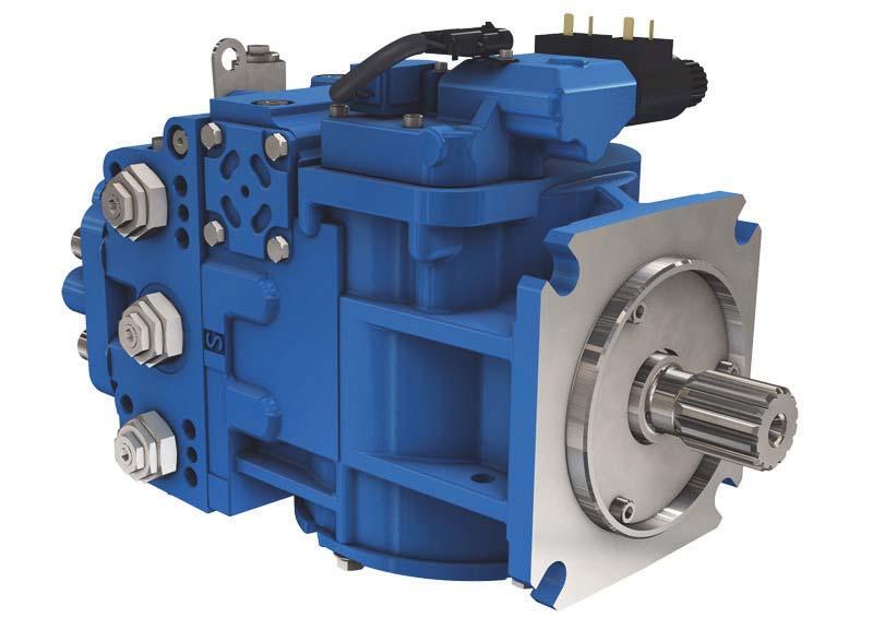
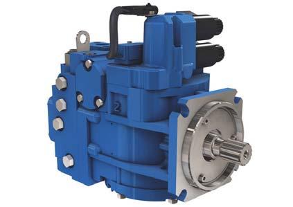
2 Variable displacement pump POCLAIN HYDRAULICS Design Piston Slipper Slider block Servo piston Servo arm Displacement control Feedback linkage Bushing Cylinder block Valve plate Cradle bearing Roller bearing Shaft seal Rear bearing Input shaf Charge pump Swashplate Cradle guide Features and options Displacement Flow at rated speed Torque at maximum displacement Mass moment of inertia of rotating component Unit cm³/rev [in³/rev.] L/min [US gal/min] N.m/bar [lbf.in/1000 PSI] kg.m² [slug.ft²] Frame [3.35] 215 [57] 0.88 [530] [0.0044] 75 [4.58] 270 [71] 1.19 [730] [0.0071] 100 [6.10] 330 [87] 1.59 [970] [0.0111] 130 [7.91] 403 [106] 2.07 [1 260] [0.0170] 180 [10.98] 468 [124] 2.87 [1 750] [0.0280] 250 [15.25] 575 [152] 3.97 [2 433] [0.0479] Weight kg [lb] 40 [88] 49 [108] 68 [150] 88 [194] 136 [300] 154 [340] Mounting (per SAE J744) C C C D E E Rotation Main ports: 4-bolt split-flange (per SAE J518 code 62) mm [in] 25.4 [1.0] 25.4 [1.0] Clockwise or Counterclockwise 25.4 [1.0] [1.25] Main port configuration Radial or axial Radial Case drain ports (SAE O-ring boss) UNF thread (in.) Other ports Shafts SAE O-ring boss [1.5] Splined, straight keyed, and tapered shafts available. Auxiliary mounting SAE SAE A, B, C SAE A, B, C, D SAE A, B, C, D, E Installation position 38.1 [1.5] Installation is recommended with control on the top or side. Consult your representative for nonconformance guidelines. The housing must remain filled with hydraulic fluid. 2 20/02/2017

3 POCLAIN HYDRAULICS Variable displacement pump CONTENT MODEL CODE 4 Model Code OPERATING PARAMETERS 9 Operating Parameters SYSTEM DESIGN PARAMETERS 13 System design Para. INSTALLATION DRAWINGS 17 Installation DrawingsI FRAME SIZE SIZE 055 FRAME SIZE FRAME SIZE FRAME SIZE FRAME SIZE FRAME SIZE OPTIONS 43 Options SIZE 250 SIZE 180 SIZE 130 SIZE 100 SIZE /02/2017 3
4 MODEL CODE Variable displacement pump POCLAIN HYDRAULICS MODEL R SIZE M P J G N Rotation Clockwise Counter clockwise R L Endcap ports Side ports 60 Twin ports 80 Displacement cm³/rev. [in³/rev.] 55 [3.35] [4.58] [6.10] [7.91] [10.98] [15.25] 250 Filtration External charge pump Pressure integral (long filter) Pressure integral (short filter) Remote pressure Remote pressure with SAE 1 1/16 thread ports for high flow Suction filtration D L P R T S Controls Solenoide control with non contact 12V feedback sensor Solenoide control with non contact 24V feedback senso* * Not compatible with SD Master and SD Premier ECU. SA SB High pressure regulation High pressure relief valves for port A and B 2 Auxiliary mounting pad SAE-A with sealed cover, 9 teeth coupling SAE-BB with sealed cover, 15 teeth coupling SAE-B with sealed cover, 13 teeth coupling SAE-C with sealed cover, 4 bolt adapter, 14 teeth coupling, (2)1/2-13 UNC SAE-D with sealed cover, 13 teeth coupling SAE-D with sealed cover, 27 teeth coupling SAE-E with sealed cover, 13 teeth coupling No auxiliary mounting pad AB BB BC CD DE DG EF NN 4 20/02/2017
5 POCLAIN HYDRAULICS Variable displacement pump CODE F L H 1 T 1 2 W Y 1 2 Z 1 2 K 1 2 Model Code Operating Parameters Displacement limitation No limiters, only for 180 C No limiters 3 Charge pressure setting 20 bar [290 PSI] bar [319 PSI] bar [348 PSI] bar [377 PSI] bar [406 PSI] bar [435 PSI] bar [464 PSI] 32 System design Para. Installation DrawingsI Shaft options Splined shaft, 21 teeth, pitch = 16/32 Splined shaft, 23 teeth, pitch = 16/32 Splined shaft, 27 teeth, pitch = 16/32 Splined shaft, 13 teeth, pitch = 8/16 Splined shaft, 14 teeth, pitch = 12/24 C6 C7 C8 F1 S1 Charging system cm³/rev. [in³/rev.] Charge pump displacement 11 [0.67] Charge pump displacement 14 [0.85] Charge pump displacement 17 [1.03] Charge pump displacement 20 [1.22] Charge pump displacement 26 [1.58] Charge pump displacement 34 [2.07] Charge pump displacement 47 [2.86] Charge pump displacement 65 [3.96] External charge pump with internal charge pressure relief valve with auxiliary mounting pad External charge pump with internal charge pressure relief valve without auxiliary mounting pad B C D E F H J K Ports (A) Servo (B) Servo Without restrictor 33 Restrictor 0,8 mm [0.031 in] A4 Restrictor 1 mm [0.039 in] P1 L N PGA PEA PGB PEB PGC PEC High pressure (Y: Setting A, Z: Setting B) bar [3770 PSI] bar [4641 PSI] bar [5076 PSI] bar [5511 PSI] bar [5801 PSI] bar [6091 PSI] Special hardware features CP valve plate and Poclain Hydraulics name tag CP valve plate, speed sensor KPPG156 and Poclain Hydraulics name tag CP valve plate (low noise) and Poclain Hydraulics name tag CP valve plate (low noise), speed sensor KPPG 156 and Poclain Hydraulics name tag CP ; additional springs on swash plate return to neutral and Poclain Hydraulics name tag CP ; additional springs on swash plate return to neutral and Poclain Hydraulics name tag with a speed sensor KPPG156 Options SIZE 250 SIZE 180 SIZE 130 SIZE 100 SIZE 075 SIZE /02/2017 5
6 Variable displacement pump POCLAIN HYDRAULICS Possible configurations Standard Not available Rotation (R1) Option Description R Clockwise L Counter clockwise Controls (M) Option Description SA Solenoid control 12V with non contact feedback sensor SB Solenoid control 24V with non contact feedback sensor High pressure regulation (P) Option Description High pressure relief valves for port A and B Auxiliary mounting pad (J) Option Description AB SAE-A with sealed cover, 9 teeth coupling BB SAE-BB with sealed cover, 15 teeth coupling BC SAE-B with sealed cover, 13 teeth coupling SAE-C with sealed cover, 4 bolt adapter, CD 14 teeth coupling, (2)1/2-13 UNC DE SAE-D with sealed cover, 13 teeth coupling DG SAE-D with sealed cover, 27 teeth coupling EF SAE-E with sealed cover, 13 teeth coupling NN No auxiliary mounting pad Endcap ports (G) Option Description Side ports Twin ports Filtration (N) Option Description D External charge pump - L Pressure integral (long filter) - - P Pressure integral (short filter) - - R Remote pressure - - T Remote pressure with SAE /16 thread ports for high flow S Suction filtration Displacement limitation (F) Option Description C No limiters, only for No limiters - Shaft options Option Description C6 Splined shaft, 21 teeth, pitch = 16/ C7 Splined shaft, 23 teeth, pitch = 16/ C8 Splined shaft, 27 teeth, pitch = 16/32Splined shaft, 27 teeth, pitch = 16/ F1 Splined shaft, 13 teeth, pitch = 8/16Splined shaft, 13 teeth, pitch = 8/ S1 Splined shaft, 14 teeth, pitch = 12/ /02/2017
7 POCLAIN HYDRAULICS Variable displacement pump Standard Not available Charging system (H) Option Description cm³/rev. [in³/rev.] B Charge pump displacement 11 [0.67] C Charge pump displacement 14 [0.85] D Charge pump displacement 17 [1.03] E Charge pump displacement 20 [1.22] F Charge pump displacement 26 [1.58] H Charge pump displacement 34 [2.07] J Charge pump displacement 47 [2.86] K Charge pump displacement 65 [3.96] L External charge pump with internal charge pressure relief valve - N External charge pump with internal charge pressure relief valve for units with no auxiliary mounting pad - - Restrictors (T) Option Ports (A) servo (B) servo Without restrictors A4 Restrictor 0,8 mm [0.031 in] P1 Restrictor 1 mm [0.039 in] Special hardwre features (W) Option Description PGA CP15 + 0,5 valve plate and Poclain Hydraulics name tag - PEA CP15 + 0,5 valve plate and Poclain Hydraulics name tag - with a speed sensor KPPG156 PGB CP30 + 4,3 and Poclain Hydraulics name tag (Low noise) PEB CP30 + 4,3 and Poclain Hydraulics name tag with speed sensor KPPG (Low noise) - - PGC CP ; additional springs on swash plate return to neutral and Poclain Hydraulics name tag PEC CP ; additional springs on swash plate return to neutral and Poclain Hydraulics name tag with a speed sensor KPPG156 High pressure (Y: setting A; Z: setting B) Option Description bar bar bar bar bar bar Charge pressure setting (K) Option Description bar bar bar bar bar bar bar Model Code Operating Parameters System design Para. Installation DrawingsI SIZE 055 Options SIZE 250 SIZE 180 SIZE 130 SIZE 100 SIZE /02/2017 7
8 Variable displacement pump POCLAIN HYDRAULICS Methodology : This document is intended for manufacturers of machines that incorporate Poclain Hydraulics products. It describes the technical characteristics of Poclain Hydraulics products and specifies installation conditions that will ensure optimum operation. This document includes important comments concerning safety. They are indicated in the following way: Safety comment. This document also includes essential operating instructions for the product and general information. These are indicated in the following way: Essential instructions. General information. Information on the model code. Weight of component without oil. Volume of oil. Units. Tightening torque. Screws. Information intended for Poclain-Hydraulics personnel. The views in this document are created using metric standards. The dimensional data is given in mm and in inches (inches are between brackets and italic) 8 20/02/2017
9 POCLAIN HYDRAULICS Variable displacement pump OPERATING PARAMETERS Operating parameters Unit Frame size Input speed Minimum 500 Continuous min -1 (rpm) Maximum System pressure Rated 420 [6000] Maximum bar [PSI] 480 [7000] Minimum low loop 10 [145] Inlet pressure (charge inlet) Minimum (continuous) bar (abs.) 0.7 [9] Minimum (cold start) [in. Hg vac.] 0.2 [24] Case pressure Continuous 3 [43] bar [PSI] Maximum (cold start) 5 [73] Overviews Maintain operating parameters within prescribed limits during all operating conditions. This section defines operating limits given in the table Operating parameters. Model Code Operating Parameters System design Para. Installation Drawings SIZE 055 Input speed Minimum speed is the lowest input speed recommended during engine idle condition. Operating below minimum speed limits the pump s ability to maintain adequate flow for lubrication and power transmission. Continuous speed is the highest input speed recommended at full power condition. Operating at or below this speed should yield satisfactory product life. Maximum speed is the highest operating speed permitted. Exceeding maximum speed reduces product life and can cause loss of hydrostatic power and braking capacity. Never exceed the maximum speed limit under any operating conditions. Exceeding maximum speed may cause a loss of hydrostatic drive line power and braking capacity. You must provide a braking system, redundant to the hydrostatic transmission, sufficient to stop and hold the vehicle or machine in the event of hydrostatic drive power loss. System pressure System pressure is the differential pressure between system ports A and B. It is the dominant operating variable affecting hydraulic unit life. High system pressure, which results from high load, reduces expected life. System pressure must remain at or below continuous pressure during normal operation to achieve expected life. Continuous pressure is the average, regularly occurring operating pressure. Operating at or below this pressure should yield satisfactory product life. Maximum pressure is the highest intermittent pressure allowed. Maximum machine load should never exceed this pressure. For all applications, the load should move below this pressure. All pressure limits are differential pressures referenced to low loop (charge) pressure. Substract low loop pressure from gauge readings to compute the differential. Options SIZE 250 SIZE 180 SIZE 130 SIZE 100 SIZE /02/2017 9
10 Variable displacement pump POCLAIN HYDRAULICS Case pressure Under normal operating conditions, the maximum continuous case pressure must not exceed 3 bar [44 PSI]. Maximum allowable intermittent case pressure during cold start must not exceed 5 bar [73 PSI]. Size drain plumbing accordingly. Operation with case pressure in excess of these limits may damage seals, gaskets, and/or housings, causing external leakage. Performance may also be affected since charge and system pressure are additive to case pressure. Fluid specifications Viscosity Unit Minimum 7 [49] Continuous mm²/sec (cst) [SUS] [70-370] Maximum 1600 [7500] Temperature Minimum -40 [-40] Continuous C [ F] 104 [220] Maximum 115 [240] Filtration Hydraulic Fluids Unit Cleanliness 18/13 or better per ISO 4406 Efficiency (suction filtration) =75 ( 10 2) Efficiency (charge filtration) =75 ( 10 10) Recommended inlet screen size m [ in] General Recommendations Poclain hydraulics recommends the use of hydraulic fluids defined by the ISO and ISO standards. For temperate climates, the following types are recommended. HM 46 or HM 48 for fixed installations. HV 46 or HV 68 for mobile installations. HEES 46 for mobile installations. These specifications correspond to category 91H of the CETOP standard, parts 1, 2 and 3 of the DIN standard, and grades VG32, VG 46 and VG68 of the ISO standards. It is also possible to use ATF, HD, HFB, HFC or HFD type hydraulic fluid upon Poclain Hydraulics specific approval of the components operating conditions. Standardized designations for the fluids HM : Mineral fluids having specific antioxidant, anticorrosion and antiwear properties (HLP equivalent to DIN parts 1 and 2). HV : HM mineral fluids providing improved temperature and viscosity properties (DIN part 3). HEES :Biodegradable fluids based on organic esters. It is also possible to use a fluid that meets the biodegradability criteria and is compatible in the event of accidental food contact. The BIOHYDRAN FG 46 fluid designed by the company Total has undergone testing of its properties and performance on our test benches. Since this type of fluid has not yet been categorized, it is the responsibility of machine manufacturers to validate its compatibility with all of the components used in order to guarantee that the intended functions will be fulfilled (specifically the brakes' hold on a slope and emergency braking) and this for the desired life time of all equipment items. For biodegradable fluids, consult your Poclain Hydraulics application engineer Class32 (ISO VG 32) : Viscosity of 32 cst at 40 C. Class46 (ISO VG 46) : Viscosity of 46 cst at 40 C. Class68 (ISO VG 68) : Viscosity of 68 cst at 40 C. During operation, the temperature of the motors must be between 0 C [32 F] and 80 C [176 F]; the minimum and maximum temperatures may be exceeded momentarily by ± 20 C [± 68 F] for a duration of less than 30 minutes. For all applications outside these limits, please consult with your Poclain Hydraulics application engineer /02/2017
11 POCLAIN HYDRAULICS Variable displacement pump Efficiency Pump performance as a function of operating speed The figure below shows typical overall and volumetric efficiencies for P90 pumps with system pressures of 210 and 420 bar [3000 and 6000 PSI], speed as percent of rated speed, and a fluid viscosity of 8 mm 2 /s (cst) [50 SUS]. Rendement global et rendement volumétrique à la cylindrée maximaleoverall efficiency ( t ) and volumetric efficiency ( v ) at maximum displacement Efficiency % SIZE 055 System design Para. Model Code Installation Drawings Operating Parameters Pump performance as a function of pressure and speed The following performance maps show typical overall efficiencies for P90 pumps with system pressures from 70 to 420 bar [1 000 to PSI] at 2/3 of rated speed varying between 1/4 to maximum displacement. These efficiency maps apply to all frame sizes. Overall efficiency at maximum displacement PSI bar Speed % of rated continuous speed Speed % of rated continuous speed System pressure PSI Pump overall ( t ) efficiency at 2/3 rated speed Options SIZE 250 SIZE 180 SIZE 130 SIZE 100 SIZE 075 bar Percent of maximum displacement 20/02/
12 Variable displacement pump POCLAIN HYDRAULICS 12 20/02/2017
13 POCLAIN HYDRAULICS Variable displacement pump SYSTEM DESIGN PARAMETERS Fluid and filtration To prevent premature wear, it is imperative that only clean fluid enter the hydrostatic transmission circuit. A filter capable of controlling the fluid cleanliness to ISO 4406 class 22/18/13 (SAE J1165) or better under normal operating conditions is recommended. The filter may be located either on the inlet (suction filtration) or discharge (charge pressure filtration) side of the charge pump. The selection of a filter depends on a number of factors including the contaminant ingression rate, the generation of contaminants in the system, the required fluid cleanliness, and the desired maintenance interval. Filters are selected to meet the above requirements using rating parameters of efficiency and capacity. Filter efficiency may be measured with a Beta ratio 1 ( X ). For simple suction-filtered closed circuit transmissions and open circuit transmissions with return line filtration, a filter with a -ratio within the range of = 75 ( 10 2) or better has been found to be satisfactory. For some open circuit systems, and closed circuits with cylinders being supplied from the same reservoir, a considerably higher filter efficiency is recommended. This also applies to systems with gears or clutches using a common reservoir. For these systems, a charge pressure or return filtration system with a filter -ratio in the range of = 75 ( 10 10) or better is typically required. Because each system is unique, only a thorough testing and evaluation program can fully validate the filtration system. Charge pressure The charge pressure setting listed in the model code is based on the charge flow across the charge pressure relief valve at fluid temperature of 50 C [120 F]. Independent braking system The loss of hydrostatic drive line power, in any mode of operation (forward, neutral, or reverse) may cause the system to lose hydrostatic braking capacity. You must provide a braking system, redundant to the hydrostatic transmission, sufficient to stop and hold the vehicle or machine in the event of hydrostatic drive power loss. Reservoir The reservoir should be designed to accommodate maximum volume changes during all system operating modes and to promote deaeration of the fluid as it passes through the tank. A suggested minimum total reservoir volume is 5/8 of the maximum charge pump flow per minute with a minimum fluid volume equal to 1/2 of the maximum charge pump flow per minute. This allows 30 seconds fluid dwell for removing entrained air at the maximum return flow. This is usually adequate to allow for a closed reservoir (no breather) in most applications. Locate the reservoir outlet (charge pump inlet) above the bottom of the reservoir to take advantage of gravity separation and prevent large foreign particles from entering the charge inlet line. A 125 μm screen over the outlet port is recommended. Position the reservoir inlet (fluid return) to discharge below the normal fluid level, toward the interior of the tank. A baffle (or baffles) will further promote de-aeration and reduce surging of the fluid. 1 Filter x-ratio is a measure of filter efficiency defined by ISO It is defined as the ratio of the number of particles greater than a given diameter ( x in microns) upstream of the filter to the number of these particles. Model Code Operating Parameters System design Para. Installation Drawings SIZE 055 Options SIZE 250 SIZE 180 SIZE 130 SIZE 100 SIZE /02/
14 Variable displacement pump POCLAIN HYDRAULICS Case drain A case drain line must be connected to one of the case outlets (L1 or L2) to return internal leakage to the system reservoir. The higher of the two case outlets should be used to promote complete filling of the case. Since case drain fluid is typically the hottest fluid in the system, it is advantageous to return this flow through the heat exchanger. Sizing equations The following equations are helpful when sizing hydraulic pumps. Generally, the sizing process is initiated by an evaluation of the machine system to determine the required motor speed and torque to perform the necessary work function. First, the motor is sized to transmit the maximum required torque. The pump is then selected as a flow source to achieve the maximum motor speed. SI units V g.n. v Output flow Q = (l/min) V g = 1000 Displacement per revolution (cm 3 /tr) Input torque M = V g. p (N.m) p = p o - p i (system pressure) 20.. m (bar) Input power P = n = M. n. Q. p Speed (tr/mn) = (kw) v = Volumetric efficiency t m = Mechanical efficiency t = Overall efficiency ( v. m) US units V g.n. v Output flow Q = (US gal/min) V g = 231 Displacement per revolution (in 3 /rev) Input torque M = V g. p (lbf.in) p = p o - p i (system pressure) 2.. m (bar) Input power P = n = Speed (rpm) M.n. Q. p = (hp) v = Volumetric efficiency t m = Mechanical efficiency t = Overall efficiency ( v. m) 14 20/02/2017
15 POCLAIN HYDRAULICS Variable displacement pump Shaft Loads Normal bearing life in B 10 hours is shown in the table below. The figures reflect a continuous differential pressure of 240 bar [3500 PSI], 1800 min -1 (rpm) shaft speed, maximum displacement, and no external shaft side load. The data is based on a 50% forward, 50% reverse duty cycle, standard charge pump size, and standard charge pressure. P90 pumps are designed with bearings that can accept external radial and thrust loads. The external radial shaft load limits are a function of the load position and orientation, and the operating conditions of the unit. The maximum allowable radial load (Re), is based on the maximum external moment (Me), and the distance (L) from the mounting flange to the load. It may be determined using the table and formula below. Thrust (axial) load limits are also shown. Re = Me / L All external shaft loads affect bearing life. In applications with external shaft loads, minimize the impact by positioning the load at 90 or 270 as shown in the figure. Contact your Poclain Hydraulics representative for an evaluation of unit bearing life if: continuously applied external loads exceed 25 % of the maximum allowable radial load (Re). the pump swashplate is positioned on one side of center all or most of the time. the unit bearing life (B 10 ) is critical. Bearing life Frame size Bearing life B 10 hrs Radial and thrust load position Parameter External moment (Me) N.m [lbf.in] Maximum shaft thrust in (T in ) N [lbf] Maximum shaft thrust out (T out ) N [lbf] 90 Re 0 Re 180 Re Allowable external shaft load Frame size [893] 3340 [750] 910 [204] 270 Re 118 [1044] 4300 [966] 930 [209] T out T in 126 [1115] 5160 [1160] 1000 [224] Re L Pump swashplate 140 [1239] 5270 [1184] 688 [154] 161 [1425] 7000 [1573] 1180 [265] 176 [1557] 7826 [1759] 1693 [380] Model Code Operating Parameters System design Para. Installation Drawings SIZE 055 Options SIZE 250 SIZE 180 SIZE 130 SIZE 100 SIZE /02/
16 Variable displacement pump POCLAIN HYDRAULICS 16 20/02/2017
17 POCLAIN HYDRAULICS Variable displacement pump Pump INSTALLATION DRAWINGS SB1 Model Code Operating Parameters Vbp A B P T SB2 M4 M5 S2 S1 M1 A M3 System design Para. Installation Drawings By-pass valve (Vbp) and restrictors are in option By-pass Valve : KV-4/2-3KO-6-1B-12DC (P/N ) B SIZE 055 In case of electronic failure: The valve is not powered. The pump is able to return to its neutral position slowly to avoid machine jerk. During normal operating or shifting: The valve is powered. The pump has a very short response time to allow soft shifting of Poclain Hydraulics motors. Orifices are by passed to bring maximum flow directly to the servo cylinders. Ports Ports size S Frame size L1 L2 M A and B 1 0flange SAE J518 code /4 flange SAE J518 code /2 flange SAE J518 code 62 S 1-5/16-12 UN 2B 1-5/8-12 UN 2B 1-1/2 flange SAE J518 code 61 L1 and L2 1-1/16-12 UN 2B 1-5/16-12 UN 2B 1-5/8-12 UN 2B M1, M2 and M3 9/16-18 UNF 2B M4 and M5 7/16-20 UNF 2B 9/16-18 UNF 2B A et B : Main system of the loop (input / output) S : charge (feed) inlet L1 and L2 : case drain M1 and M2 : A and B ports pressure gauge M3 : charge (feed) pressure gauge M4 and M5 : control pressure gauge Options SIZE 250 SIZE 180 SIZE 130 SIZE 100 SIZE /02/
18 Variable displacement pump POCLAIN HYDRAULICS SA or SB control Features : Proportional electronic control driven by the Poclain Hydraulics electronic boxes. Our electronic control boxes control the displacement and the direction of the flow while monitoring permanently the functioning parameters of the engine and of the complete hydraulic system. Two contamination resistant (IP65) solenoid valves controls the displacement and the direction of the flow. A sensor linked to the swash plate monitors permanently the actual displacement setting. For SD Master and SD Premier ECU use SA control whatever the supply voltage (12V or 24V). Shaft rotation Clockwise counter clockwise Actuated solenoid S1 S2 S1 S2 Servo cylinder M5 M4 M5 M4 Port A flow outlet inlet inlet outlet Port B flow inlet outlet outlet inlet Control (pump size 055) - Mating connector: X* - Supply voltage: 12 V DC max. (SA control) 24 V DC max. (SB control) - Intensity: A max. (SA control) A max. (SB control) Control (pump size from 075 to 250) - Mating connector: Z - Supply voltage: 5V DC max. *DIN A must be without integrated diode. Position sensor Pump displacement Feedback angle for max displacement / Hydraulic symbol : Position sensor C +5V B Signal A Ground 18 20/02/2017
19 POCLAIN HYDRAULICS Control SA or SB, Side ports FRAME SIZE 055 Variable displacement pump View "Z" Model Code Gauge port M2 system pressure B Coupling may not protrude beyond this surface Length of full spline Operating Parameters Splined shaft option S1 Installation Drawings System design Para. Gauge port M1 system pressure A Approximate center of gravity Port L1 case drain use highest port as outlet 1-1/16-12UN-2B View "Y" Gauge port M5 Servo pressure 7/16-20UNF-2B Ports A and B psi split flange boss per SAE J518 (Code 62) 7/16-14UNC-2B except 21 [0.83] minimum full thread Gauge port M4 servo pressure 7/16-20UNF-2B Approximate Shaft spline data: center of gravity Pitch diameter = [1.1667] Pressure angle = 30 Number of teeth = 14 Pitch = 12/24 ANSI B , class 5, Coupling may not protrude beyond this surface Length of full spline High pressure relief valve Shaft spline data: : Pitch diameter= [1.3125] Pressure angle = 30 Number of teeth= 21 Pitch = 16/32 ANSI B , class 5, Fillet Root side fit Splined shaft option C6 Gauge port M3 charge pressure High pressure relief valve Charge pressure relief valve Port S: Charge pump inlet 1-5/16-12UN-2B Options SIZE 250 SIZE 180 SIZE 130 SIZE 100 SIZE 075 SIZE 055 Port L2 case drain 1-1/16-12UN-2B 20/02/
20 Variable displacement pump POCLAIN HYDRAULICS Control SA or SB, Twin ports Gauge port M2 system pressure B Port S: charge pump inlet 1-5/16-12UN-2B Ports A and B psi split flange boss per SAE J518 (code 62) 7/16-14UNC-2B 21 [0.83] minimum full thread Gauge port M1: system pressure A View "Y" port S 20 20/02/2017
21 POCLAIN HYDRAULICS Variable displacement pump SAE A (option AB), Side ports Coupling spline data: Pitch diameter = [0.5625] Pressure angle = 30 Number of teeth = 9 Pitch = 16/32 ANSI B , class 6, Length of spline = [1.46] Model Code System design Para. Operating Parameters Installation Drawings See table in page 41 for O-ring size. 4 threads 3/8-16UNC-2B 17 [0.67] deep SIZE 055 SAE B (option BC), Side ports Coupling spline data: Pitch diameter = [0.8125] Pressure angle = 30 Number of teeth = 13 Pitch = 16/32 ANSI B , class 6, Length of spline = [1.16] See table in page 41 for O-ring size. 4 threads 1/2-13UNC-2B 22.8 [0.89] deep Options SIZE 250 SIZE 180 SIZE 130 SIZE 100 SIZE /02/
22 Variable displacement pump POCLAIN HYDRAULICS SAE C (option CD), Side ports Coupling spline data: Pitch diameter = [1.167] Pressure angle = 30 Number of teeth = 14 Pitch = 12/24 ANSI B , class 6, Length of spline = [0.747] See table in page 41 for O-ring size. 4 threads 1/2-13UNC-2B 22 [0.87] deep SAE B-B (option BB), Side ports Coupling spline data: : Pitch diameter = [0.9375] Pressure angle = 30 Number of teeth = 15 Pitch = 16/32 ANSI B , class 6, Length of spline = [0.96] See table in page 41 for O-ring size. 4 threads 1/2-13UNC-2B 22 [0.87] deep 22 20/02/2017
23 POCLAIN HYDRAULICS Control SA or SB, Side ports Gauge port M2 system pressure B FRAME SIZE 075 Coupling may not protrude beyond this surface Length of full spline Splined shaft option S1 Variable displacement pump View "Z" Model Code ,05 0 [ 5-0,002 ] System design Para. Operating Parameters Gauge port M1 system pressure A Approximate center of gravity Shaft spline data: : Pitch diameter = [1.1667] Pressure angle = 30 Number of teeth = 14 Pitch = 12/24 ANSI B , class 5, Approximate center of gravity Port L2 case drain 1-1/16-12UN-2B Installation Drawings SIZE 055 Port L1 case drain use highest port as outlet 1-1/16-12UN-2B Ports A and B psi split flange boss per SAE J518 (Code 62) 7/16-14UNC-2B minimum full thread View "Y" Gauge port M5 servo pressure Gauge port M4 servo pressure Coupling may not protrude beyond this surface Length of full spline Splined shaft option C7 High pressure relief valve Gauge port M3 charge pressure High pressure relief valve Shaft spline data: : Pitch diameter = [1.4375] Pressure angle = 30 Number of teeth = 23 Pitch = 16/32 ANSI B , class 5, Fillet Root side fit Charge pressure relief valve Port S: Charge pump inlet 1-5/16-12UN-2B Options SIZE 250 SIZE 180 SIZE 130 SIZE 100 SIZE /02/
24 Variable displacement pump POCLAIN HYDRAULICS Control SA or SB, Twin ports Gauge port M2 system pressure B Port S: charge pump inlet 1-5/16-12UN-2B Ports A and B psi split flange boss per SAE J518 (Code 62) 7/16-14UNC-2B except 20.8 [0.82] minimum full thread Gauge port M1: system pressure A View "Y" 24 20/02/2017
25 POCLAIN HYDRAULICS Variable displacement pump SAE A (option AB), Side ports Coupling spline data: : Pitch diameter = [0.5625] Pressure angle = 30 Number of teeth = 9 Pitch = 16/32 ANSI B , class 6, Length of spline = [1.46] Model Code System design Para. Operating Parameters Installation Drawings See table in page 41 for O-ring size. 4 threads 3/8-16UNC-2B 17 [0.67] deep SIZE 055 SAE B (option BC), Side ports Coupling spline data: : Pitch diameter = [0.8125] Pressure angle = 30 Number of teeth = 13 Pitch = 16/32 ANSI B , class 6, Length of spline = [1.16] See table in page 41 for O-ring size. 4 threads 1/2-13UNC-2B 22 [0.87] deep Options SIZE 250 SIZE 180 SIZE 130 SIZE 100 SIZE /02/
26 Variable displacement pump POCLAIN HYDRAULICS SAE C (option CD), Side ports Coupling spline data: Pitch diameter = [1.167] Pressure angle = 30 Number of teeth = 14 Pitch = 12/24 ANSI B , class 6, Length of spline = [0.747] See table in page 41 for O-ring size. 6 threads 1/2-13UNC-2B 22 [0.87] deep SAE B-B (option BB), side ports Coupling spline data: : Pitch diameter = [0.9375] Pressure angle = 30 Number of teeth = 15 Pitch = 16/32 ANSI B , class 6, Length of spline = [0.96] See table in page 41 for O-ring size. 4 threads 1/2-13UNC-2B 22 [0.87] deep 26 20/02/2017
27 POCLAIN HYDRAULICS Variable displacement pump Control SA or SB, Side ports FRAME SIZE 100 Model Code Gauge port M2 system pressure B port A port B port L1 Coupling may not protrude beyond this surface Length of full Splined shaft option F1 port L2 View "Z" Operating Parameters System design Para. Installation Drawings Gauge port M1 system pressure A Port L1 case drain use highest port as outlet 1-1/16-12UN-2B Ports A and B psi split flange boss per SAE J518 (Code 62) 7/16-14UNC-2B minimum full thread Approximate center of gravity port S View "Y" port L2 Gauge port M4 servo pressure Gauge port M5 Servo pressure Shaft spline data: Pitch diameter = [1.625] Pressure angle = 30 Number of teeth = 13 Pitch = 8/16 ANSI B , class 5, Coupling may not protrude beyond this surface Length of full spline Splined shaft option C7 Approximate center of gravity High pressure relief valve Gauge port M3 charge pressure High pressure relief valve Shaft spline data: Pitch diameter= [1.4375] Pressure angle= 30 Number of teeth= 23 Pitch = 16/32 ANSI B , class 5, Fillet Root side fit Charge pressure relief valve Port S: Charge pump inlet 1-5/8-12UN-2B Port L2 case drain 1-1/16-12UN-2B Options SIZE 250 SIZE 180 SIZE 130 SIZE 100 SIZE 075 SIZE /02/
28 Variable displacement pump POCLAIN HYDRAULICS Control SA or SB, Twin ports Gauge port M2 system pressure B Coupling may not protrude beyond this surface Length of full spline Port S: charge pump inlet 1-5/8-12UN-2B Splined shaft option S1 Ports A and B psi split flange boss per SAE J518 (Code 62) 7/16-14UNC-2B 21 [0.83] minimum full thread Gauge port M1: system pressure A View "Y" Shaft spline data: Pitch diameter= [1.1667] Pressure angle= 30 Number of teeth= 14 Pitch = 12/24 ANSI B , class 5, Fillet Root side fit port S 28 20/02/2017
29 POCLAIN HYDRAULICS Variable displacement pump Control SA or SB, Twin ports Gauge port M2 system pressure B Port S: charge pump inlet 1-5/8-12UN-2B FRAME SIZE 130 Coupling may not protrude beyond this surface Length of full spline Splined shaft option F1 View "Z" Model Code port L2 Installation Drawings port L1 System design Para. Operating Parameters Ports A and B 1-1/ psi split flange boss per SAE J518 (Code 62) 1/2-13UNC-2B 23 [0.906] minimum full thread Gauge port M1 system pressure A Approximate center of gravity View "Y" Gauge port M4 servo pressure Gauge port M5 servo pressure Port L1 case drain use highest port as outlet 1-5/16-12UN-2B port L2 Shaft spline data: Pitch diameter= [1.625] Pressure angle= 30 Number of teeth= 13 Pitch = 8/16 ANSI B , class 5, Coupling may not protrude beyond this surface Length of full spline Splined shaft option C8 High pressure relief valve Approximate center of gravity Gauge port M3 charge pressure High pressure relief valve Shaft spline data: Pitch diameter= [1.6875] Pressure angle= 30 Number of teeth= 27 Pitch= 16/32 ANSI B , class 5, Fillet Root side fit Charge pressure relief valve Options SIZE 250 SIZE 180 SIZE 130 SIZE 100 SIZE 075 SIZE 055 Port L2 case drain 1-5/16-12UN-2B 20/02/
30 Variable displacement pump POCLAIN HYDRAULICS SAE A (option AB), Twin ports Coupling spline data: Pitch diameter = [0.5625] Pressure angle = 30 Number of teeth = 9 Pitch = 16/32 ANSI B , class 6, Length of spline = 22.4 [0.88] See table in page 41 for O-ring size. 4 threads 3/8-16UNC-2B 17 [0.67] deep SAE B (option BC), Twin ports Coupling spline data: Pitch diameter = [0.8125] Pressure angle = 30 Number of teeth = 13 Pitch = 16/32 ANSI B , class 6, Length of spline = [1.1] See table in page 41 for O-ring size. 4 threads 1/2-13UNC-2B 22 [0.87] deep 30 20/02/2017
31 POCLAIN HYDRAULICS Variable displacement pump SAE C (option CD), Twin ports Coupling spline data: Pitch diameter = [1.167] Pressure angle = 30 Number of teeth = 14 Pitch = 12/24 ANSI B , class 6, Length of spline = [1.18] Model Code System design Para. Operating Parameters Installation Drawings See table in page 41 for O-ring size. 6 threads 1/2-13UNC-2B 22 [0.87] deep SIZE 055 SAE D (option DE), Twin ports Coupling spline data: Pitch diameter = [1.625] Pressure angle = 30 Number of teeth = 13 Pitch = 8/16 ANSI B , class 6, Length of spline = [0.993] See table in page 41 for O-ring size. 4 threads 3/4-10UNC-2B 41 [1.6] deep Options SIZE 250 SIZE 180 SIZE 130 SIZE 100 SIZE /02/
32 Variable displacement pump POCLAIN HYDRAULICS SAE B-B (option BB), Twin ports Coupling spline data: Pitch diameter = [0.9375] Pressure angle = 30 Number of teeth = 15 Pitch = 16/32 ANSI B , class 6, Length of spline = [0.96] See table in page 41 for O-ring size. 4 threads 1/2-13UNC-2B 22 [0.87] deep 32 20/02/2017
33 POCLAIN HYDRAULICS Variable displacement pump Control SA or SB, Twin ports FRAME SIZE 180 Model Code Gauge port M2 system pressure B Port S: charge pump inlet 1-5/8-12UN-2B port L1 Coupling may not protrude beyond this surface Length of full spline Splined shaft option F1 View "Z" port L2 Operating Parameters System design Para. Installation Drawings Ports A and B 1-1/ psi split flange boss per SAE J518 (Code 62) 1/2-13UNC-2B 23 [0.906] minimum full thread Gauge port M1 system pressure A Approximate center of gravity View "Y" Port L1 case drain use highest port as outlet 1-5/8-12UN-2B port L2 Gauge port M4 servo pressure Gauge port M5 servo pressure Shaft spline data: Pitch diameter= [1.625] Pressure angle= 30 Approximate Number of teeth= 13 center Pitch= 8/16 of gravity ANSI B , class 5, Coupling may not protrude beyond this surface Length of full spline Splined shaft option C8 High pressure relief valve Gauge port M3 charge pressure High pressure relief valve Shaft spline data: Pitch diameter= [1.6875] Pressure angle= 30 Number of teeth= 27 Pitch= 16/32 ANSI B , class 5, Fillet Root side fit Port L2 case drain 1-5/8-12UN-2B SIZE 055 Options SIZE 250 SIZE 180 SIZE 130 SIZE 100 SIZE /02/
34 Variable displacement pump POCLAIN HYDRAULICS SAE A (option AB), Twin ports Coupling spline data: Pitch diameter = [0.5625] Pressure angle = 30 Number of teeth = 9 Pitch = 16/32 ANSI B , class 6, Length of spline = 17.8 [0.70] See table in page 41 for O-ring size. 4 threads 3/8-16UNC-2B 17.8 [0.70]deep SAE B (option BC), Twin ports Coupling spline data: Pitch diameter = [0.8125] Pressure angle = 30 Number of teeth = 13 Pitch = 16/32 ANSI B , class 6, Length of spline = 29.5 [1.16] See table in page 41 for O-ring size. 4 threads 1/2-13UNC-2B 22 [0.87] deep 34 20/02/2017
35 POCLAIN HYDRAULICS Variable displacement pump SAE C (option CD), Twin ports Coupling spline data: Pitch diameter = [1.167] Pressure angle = 30 Number of teeth = 14 Pitch = 12/24 ANSI B , class 6, Length of spline = 22.1 [0.87] Model Code Operating Parameters Installation Drawings System design Para. See table in page 41 for O-ring size. 6 threads 1/2-13UNC-2B 22 [0.87] deep SIZE 055 SAE D (option DE), Twin ports Coupling spline data: Pitch diameter = [1.625] Pressure angle = 30 Number of teeth = 13 Pitch = 8/16 ANSI B , class 6, Length of spline = 25.9 [1.02] See table in page 41 for O-ring size. 4 threads 3/4-10UNC-2B 41 [1.61] deep Options SIZE 250 SIZE 180 SIZE 130 SIZE 100 SIZE /02/
36 Variable displacement pump POCLAIN HYDRAULICS SAE E (option EF), Twin ports Coupling spline data: Pitch diameter = [1.625] Pressure angle = 30 Number of teeth = 13 Pitch = 8/16 ANSI B , class 6, Length of spline = 25.9 [1.02] See table in page 41 for O-ring size. 4 threads 3/4-10UNC-2B 41 [1.61] deep SAE B-B (option BB), Twin ports Coupling spline data: Pitch diameter = [0.9375] Pressure angle = 30 Number of teeth = 15 Pitch = 16/32 ANSI B , class 6, Length of spline = [0.96] See table in page 41 for O-ring size. 4 threads 1/2-13UNC-2B 22 [0.87] deep 36 20/02/2017
37 POCLAIN HYDRAULICS Control SA or SB, Twin ports FRAME SIZE 250 Variable displacement pump Model Code Coupling may not protrude beyond this surface Length of full spline Splined shaft option F1 View "Z" port L1 Operating Parameters System design Para. Port S charge pump Inlet 1-1/ psi split flange boss per SAE J518 (Code 61) 1/2-13UNC-2B 24 [0.94] minimum full thread Ports A and B 1-1/ psi split flange boss per SAE J518 (Code 62) 5/8-11UNC-2B 25 [0.98] minimum full thread Approximate center of gravity View "Y" Port L1 case drain use highest port as outlet 1-5/8-12UN-2B port L2 Gauge port M4 servo pressure Gauge port M5 servo pressure Shaft spline data: Pitch diameter= [1.625] Pressure angle= 30 Approximate Number of teeth= 13 center Pitch= 8/16 of gravity ANSI B , class 5, Coupling may not protrude beyond this surface Length of full spline High pressure relief valve Gauge port M3 charge pressure Shaft spline data: Pitch diameter= [1.6875] Pressure angle= 30 Number of teeth= 27 Pitch= 16/32 ANSI B , class 5, Fillet Root side fit Splined shaft option C8 High pressure relief valve port L2 Charge pressure relief valve Gauge port M10 charge pump inlet Port L2 case drain 1-5/8-12UN-2B Gauge port M2 system pressure B Gauge port M1 system pressure A Installation Drawings SIZE 055 Options SIZE 250 SIZE 180 SIZE 130 SIZE 100 SIZE /02/
38 Variable displacement pump POCLAIN HYDRAULICS SAE A (option AB), Twin ports Coupling spline data: Pitch diameter= [0.5625] Pressure angle= 30 Number of teeth= 9 Pitch= 16/32 ANSI B , class 6, Length of spline= 17.8 [0.70] See table in page 41 for O-ring size. 4 threads 3/8-16UNC-2B 17.8 [0.70] deep SAE B (option BC), Twin ports Coupling spline data: Pitch diameter= [0.8125] Pressure angle= 30 Number of teeth= 13 Pitch= 16/32 ANSI B , class 6, Length of spline= 29.5 [1.16] See table in page 41 for O-ring size. 4 threads 1/2-13UNC-2B 22 [0.87] deep 38 20/02/2017
39 POCLAIN HYDRAULICS Variable displacement pump SAE C (option CD), Twin ports Coupling spline data: Pitch diameter= [1.167] Pressure angle= 30 Number of teeth= 14 Pitch= 12/24 ANSI B , class 6, Length of spline= 22.1 [0.87] Model Code Operating Parameters System design Para. Installation Drawings See table in page 41 for O-ring size. 6 threads 1/2-13UNC-2B 22 [0.87] deep SIZE 055 SAE D (option DE), Twin ports Coupling spline data: Pitch diameter= [1.625] Pressure angle= 30 Number of teeth= 13 Pitch= 8/16 ANSI B , class 6, Length of spline= 25.9 [1.02] See table in page 41 for O-ring size. 4 threads 3/4-10UNC-2B 41 [1.61] deep Options SIZE 250 SIZE 180 SIZE 130 SIZE 100 SIZE /02/
![Variable displacement pump POCLAIN HYDRAULICS SAE E (option EF), Twin ports Coupling spline data: Pitch diameter= 41.275 [1.625] Pressure angle= 30 Number of teeth= 13 Pitch= 8/16 ANSI B92.](/docs-images/73/68148943/images/40-0.jpg "1-1970, class 6, Length of spline= 25.9 [1.02] See table in page 41 for O-ring size. 4 threads 3/4-10UNC-2B 41 [1.61] deep SAE B-B (option BB), Twin ports Coupling spline data: Pitch diameter= 23.")
40 Variable displacement pump POCLAIN HYDRAULICS SAE E (option EF), Twin ports Coupling spline data: Pitch diameter= [1.625] Pressure angle= 30 Number of teeth= 13 Pitch= 8/16 ANSI B , class 6, Length of spline= 25.9 [1.02] See table in page 41 for O-ring size. 4 threads 3/4-10UNC-2B 41 [1.61] deep SAE B-B (option BB), Twin ports Coupling spline data: Pitch diameter= [0.9375] Pressure angle= 30 Number of teeth= 15 Pitch= 16/32 ANSI B , class 6, Length of spline= [0.96] See table in page 41 for O-ring size. 4 threads 1/2-13UNC-2B 22 [0.87] deep 40 20/02/2017
41 POCLAIN HYDRAULICS Variable displacement pump O-ring size according to flange type Flange type O-ring size O-ring material P/N SAE A 82.22x2.62 FPM 70 shore A B SAE B and SAE B-B 94.92x2.62 FPM 70 shore A A25721H SAE C x2.62 FPM 70 shore A B SAE D 150x3 FPM 80 shore A A19528B SAE E x2.62 FPM 80 shore A A19530D System design Para. Model Code Operating Parameters Options SIZE 250 SIZE 180 SIZE 130 SIZE 100 SIZE 075 SIZE 055 Installation Drawings 20/02/
42 Variable displacement pump POCLAIN HYDRAULICS 42 20/02/2017

43 POCLAIN HYDRAULICS Variable displacement pump OPTIONS Model Code Shaft availability and torque ratings Fixing kit Operating Parameters Next pump Rear pump Front pump System design Para. M e2 for the second pump M e3 for the next pump M e1 for the first pump M e imput torque Installation Drawings Torque required by auxiliary pumps is additive. Ensure requirements don t exceed shaft torque ratings. SIZE 055 Shaft availability and torque ratingstypes d arbres disponibles et couples nominaux N.m [lbf.in] Shaft description Option Frame size code teeth 16/32 pitch spline C6 23 teeth 16/32 pitch spline C [10 000] Contact your Poclain Hydraulics representative for other shafts ends [14 000] 27 teeth 16/32 pitch spline C8 13 teeth 8/16 pitch spline F1 14 teeth 12/24 pitch spline S1 735 [6 500] 735 [6 500] 1580 [14 000] 1810 [16 000] Not available Not recommended for front pump in tandem configurations Rear pump Tandem pump fixing kit Front pump 2938 [26 000] 2938 [26 000] 2938 [26 000] [16 000] + [16 000] [6 500] Kit Not applicable 4 x SCREW-HEX HD,1/2-13UNC X 1.1/4 GRADE 5 (ANSI B18.2.1, SAE J429) + 4 x WASHER DIN C x O-RING120.32x2.62 N-FPM80 4 x SCREW-HEX HD, 3/4-10 UNC X 2.1/4 GRADE 5 (ANSI B18.2.1, SAE J429) + 4 x WASHER-.797 X X.184 HARDENED HRC + 1 x O-RING150.00x3.00 N-FPM80 4 x SCREW-HEX HD, 3/4-10 UNC X 2.1/ 4 GRADE 5 (ANSI B18.2.1, SAE J429) + 4 x WASHER-.797 X X.184 HARDENED HRC + 1 x O-RING164.77x2.62 N-FPM80 A19516N A19517P A19519R [16 000] + tightening torque 100 N.m 360 N.m Options SIZE 250 SIZE 180 SIZE 130 SIZE 100 SIZE /02/
44 Variable displacement pump POCLAIN HYDRAULICS Filtration options Suction filtration option S The suction filter is placed in the circuit between the reservoir and the inlet to the charge pump, as shown below. The use of a filter contamination monitor is recommended. Hydraulic fluid reservoir Manometer Filter Charge pump To low pressure loop and control Adjustable charge pressure relief valve To pump case Charge pressure filtration option R, T, P, and L The pressure filter can be mounted directly on the pump or mounted remotely for ease of servicing. A μm mesh screen, located in the reservoir or the charge inlet line, is recommended when using charge pressure filtration. This system requires a filter capable of withstanding charge pressure. Hydraulic fluid reservoir Screen Charge pump Adjustable charge pressure relief valve To low pressure side and control Filter To pump case 44 20/02/2017
45 POCLAIN HYDRAULICS Variable displacement pump High pressure relief valves When system pressure exceeds the setting of the valve, it passes oil from the high pressure system loop to the low pressure system loop. Bypass Function In some applications it is desirable to bypass fluid around the variable displacement pump when pump shaft rotation is either not possible or not desired. For example, an inoperable vehicle may be moved to a service or repair location or winched onto a trailer without operating the prime mover. To provide for this, P90 pumps are designed with a bypass function. The bypass is operated by mechanically rotating the bypass hex on both multifunction valves three (3) turns counterclockwise (CCW). This connects working loop A and B and allows fluid to circulate without rotating the pump and prime mover. Speed sensor An optional speed sensor for direct measurement of speed is available. This sensor may also be used to sense the direction of rotation. A special magnetic ring is pressed onto the outside diameter of the cylinder block and a Hall effect sensor is located in the housing. The sensor accepts supply voltage and outputs a digital pulse signal in response to the speed of the ring. The output changes its high/low state as the north and south poles of the permanently magnetized speed ring pass by the face of the sensor. The digital signal is generated at frequencies suitable for microprocessor based controls.the sensor is available with M12 connector (4 pins). P/N Supply voltage* Bypass valves are intended for moving a machine or vehicle for very short distances at very slow speeds. They are NOT intended as tow valves. Supply voltage (regulated) Required current Max. current Max. frequency Voltage output (high) Voltage output (low) Temperature range * Do not energize the 4.5 to 8.5 VDC sensor with 12 VDC battery voltage. Use a regulated power supply. If you need to energize the sensor with battery voltage, contact your Poclain Hydraulics representative for a special sensor. M12 connector (4 pins) Specifications A21674J 4.5 to 8.5 VDC 15 VDC max. 12 ma at 5 VDC, 1 Hz 20 ma at 5 VDC, 1 Hz 15 khz Supply -0.5 V min. 0.5 V max. -40 to 110 C [-40 to 230 F] Pulse frequency Frame size Pulse per revolution Mating connector Cable with right angle M12 connector (lenght 5 m) Cable with straight M12 connector (lenght 5 m) Pin Function Colour 1 Supply Brown 2 NC White 3 Signal Blue 4 Ground black P/N A04999J A07468S Keyway (Ref) Model Code Operating Parameters System design Para. Installation Drawings SIZE 055 Options SIZE 250 SIZE 180 SIZE 130 SIZE 100 SIZE /02/
46 Variable displacement pump POCLAIN HYDRAULICS Charge Pump Charge flow is required on all P90 pumps applied in closed circuit installations. The charge pump provides flow to make up internal leakage, maintain a positive pressure in the main circuit, provide flow for cooling and filtration, replace any leakage losses from external valving or auxiliary systems, and to provide flow and pressure for the control system. Many factors influence the charge flow requirements. These factors include system pressure, pump speed, pump swashplate angle, type of fluid, temperature, size of heat exchanger, length and size of hydraulic lines, control response characteristics, auxiliary flow requirements, hydrostatic motor type, etc. Unusual application conditions may require a more detailed review of charge pump sizing. Charge pressure must be maintained at a specified level under all operating conditions to prevent damage to the transmission. Poclain Hydraulics recommends testing under actual operating conditions to verify this. Charge pump sizing/selection.in most applications a general guideline is that the charge pump displacement should be at least 10% of the total displacement of all components in the system. Unusual application conditions may require a more detailed review of charge flow requirements. System features and conditions which may invalidate the 10% guideline include (but are not limited to): Continuous operation at low input speeds (< 1500 min -1 (rpm)) High shock loading Excessively long system lines (> 3m [9.8 ft]) Auxiliary flow requirements Use of low speed high torque motors Contact your Poclain Hydraulics representative for application assistance if your application includes any of these conditions. Available charge pump sizes and speed limits Option code Displacement cm³/rev [in³/rev] Rated speedmin -1 (rpm) B 11 [0.68] 4200 C 14 [0.86] 4200 D 17 [1.03] 3900 E 20 [1.20] 3600 F 26 [1.60] 3300 G 26 [1.60] 3100 (130 cm 3 pump) H 34 [2.07] 3100 J 47 [2.86] 2600 K 65 [3.96] 2300 Charge pump output flow Charge pump power requirements US gal/min L/min US gal/min kw Speed min -1 (rpm) Speed min -1 (rpm) Charge pump flow and power curves :Charge pressure: 20 bar [290 PSI] :Case drain: 80 C (8.2 cst) 180 F (53 SUS) :Reservoir temperature: 70 C (11 cst) 160 F (63 SUS) 46 20/02/2017
47 POCLAIN HYDRAULICS Variable displacement pump Auxiliary Mounting Pads * For the 055 pump the rated torque is limited to 445 N.m[3 830 lbf.in] Mating pump requirements The accompanying drawing provides the dimensions for the auxiliary pump mounting flange and shaft. Pump mounting flanges and shafts with the dimensions noted below are compatible with the auxiliary mounting pads on the P90 pumps. Auxiliary pump mounting flange and shaft Auxiliary mounting pads specifications Mounting pad size Option code Internal spline size SAE A SAE B AB BC 9 teeth 16/32 pitch 13 teeth 16/32 pitch 15 teeth SAE B-B BB 16/32 pitch SAE C CD 14 teeth 12/24 pitch SAE D SAE D SAE E DE DG EF 13 teeth 8/16 pitch 27 teeth 16/32 pitch 13 teeth 8/16 pitch Minimum spline engagement mm [in] 13.5 [0.53] 14.2 [0.56] 16.1 [0.63] 18.3 [0.72] 20.8 [0.82] 27.0 [1.06] 20.8 [0.82] Rated torque N.m [lbf.in] 107 [947] 256 [2 265] 347 [3 071] 663 * [5 868] * [10 500] [19 790] [14 489] Auxiliary pump dimensions Flange size Units P diameter B maximum D F minimum SAE A [3.25] 17.4 [0.29] 32 [1.26] 13.5 [0.53] SAE B [4.00] 10.7 [0.42] 41 [1.61] 14.2 [0.56] SAE B-B [4.00] 10.7 [0.42] 46 [1.81] 16.1 [0.63] mm [in] SAE C [5.00] 14.3 [0.56] 56 [2.20] 18.3 [0.72] SAE D [6.00] 14.3 [0.56] 75 [2.95] 20.8 [0.82] SAE E 13 teeth [6.50] 18.0 [0.71] 75 [2.95] 20.8 [0.82] Mounting flange (Ref) Minimum spline engagement Coupling preferred Model Code Operating Parameters System design Para. Installation Drawings SIZE 055 Options SIZE 250 SIZE 180 SIZE 130 SIZE 100 SIZE /02/

48 Variable displacement pump POCLAIN HYDRAULICS Mounting Flange Loads Adding tandem mounted auxiliary pumps and/or subjecting pumps to high shock loads may result in excessive loading of the mounting flange. The overhung load moment for multiple pump mounting may be estimated as shown in the accompanying figure. Overhung load example Auxiliary pad Mounting flange CG pump 2 CG pump 1 L1 L2 Estimating overhung load moments W = Weight of pump (kg) L = Distance from mounting flange to pump center of gravity (m) (refer to pump installation drawings) M R = G R (W 1 L 1 + W 2 L W n L n ) M S = G S (W 1 L 1 + W 2 L W n L n ) Where: M R = Rated load moment (N.m) M S = Shock load moment (N.m) G R = Rated (vibratory) acceleration (G s) * (m/sec²) G S = Maximum shock acceleration (G s) * (m/sec²) * Calculations will be carried out by multiplying the gravity (g = 9.81 m/sec²) with a given factor. This factor depends on the application. Allowable overhung load moment values are shown in the accompanying table. Exceeding these values requires additional pump support. Allowable overhung load moments Frame size Rated moment (M R ) N.m [lbf.in] Shock load moment (M S ) N.m [lbf.in] [14 000] [50 000] [14 000] [50 000] [14 000] [50 000] [28 000] [95 000] [54 000] [ ] [54 000] [ ] 48 20/02/2017
49 POCLAIN HYDRAULICS Variable displacement pump Integral Pressure Filter (option P and L) Gauge port M6 charge pressure before filter 9/16-18UNF Ø 94.2 maximum Ø [3.71 minimum] Flow capacity l/min [GPM] Long filter (L) 105 [27.7] Short filter (P) 60 [15.9] Model Code Operating Parameters System design Para. Gauge port M3 charge pressure after filter 9/16-18UNF F4 maximum Remote pressure without filter (option R and T) 20.3 maximum [0.80 minimum] Frame size = option P Frame size = option L F1 = short filter cartridge (option P) F2 = long filter cartridge (option L) Installation Drawings SIZE 055 Port E fromfilter 7/8-14UNF (option R) 1 1/16-12UN (option T) Port D to filter 7/8-14UNF (option R) 1 1/16-12UN (option T) F5 maximum F6 maximum F7 maximum Frame size = option R Frame size = option T Gauge port M3 charge pressure after filter 9/16-18UNF Dimensions mm [in] Frame size F1 F2 F3 F4 max. F5 max. F6 max. F7 max [6.87] [10.34] [8.19] [8.25] [4.50] [6.07] [6.68] [6.87] [10.34] [9.67] [8.44] [4.69] [6.26] [6.86] [6.87] [10.34] [11.05] [8.78] [5.03] [6.60] [7.20] [6.87] [10.34] [11.81] [9.17] [5.03] [6.99] [7.60] [12.90] [7.16] [9.32] [10.2] [13.49] [7.16] [9.32] [10.2] Options SIZE 250 SIZE 180 SIZE 130 SIZE 100 SIZE /02/
50 Variable displacement pump POCLAIN HYDRAULICS 50 20/02/2017
51 POCLAIN HYDRAULICS Variable displacement pump Options SIZE 250 SIZE 180 SIZE 130 SIZE 100 SIZE 075 SIZE 055 Installation Drawings System design Para. Operating Parameters Model Code 20/02/

52 Poclain Hydraulics reserves the right to make any modifications it deems necessary to the products described in this document without prior notification.the information contained in this document must be confirmed by Poclain Hydraulics before any order is submitted. Illustrations are not binding. The Poclain Hydraulics brand is the property of Poclain Hydraulics S.A. 20/02/2017 A18260X A18586C
P90 VARIABLE DISPLACEMENT PUMP T E C H N I C A L C A T A L O G
 P90 VARIABLE DISPLACEMENT PUMP T E C H N I C A L C A T A L O G Variable displacement pump POCLAIN HYDRAULICS Design Slider block Swashplate hold-down Servo piston Servo arm Piston Slipper Displacement
PM50 VARIABLE DISPLACEMENT PUMP CLOSED LOOP CIRCUIT T E C H N I C A L C A T A L O G
 PM50 VARIABLE DISPLACEMENT PUMP CLOSED LOOP CIRCUIT T E C H N I C A L C A T A L O G PM50 - Variable displacement pump POCLAIN HYDRAULICS OVERVIEW PM50 is a variable displacement, axial piston pump, with
MOTORS MV HYDRAULIC MOTORS T E C H N I C A L C A T A L O G
 OTORS V HYDRAULIC OTORS T E C H N I C A L C A T A L O G otors V - Hydraulic otors POCLAIN HYDRAULICS OVERVIEW Displacement Speed V2 V3 aximum cm³/rev [in³/rev.] From 3 [2.14] to 3 [3.23] From [3.3] to
PMV0 VARIABLE DISPLACEMENT PUMP CLOSED LOOP CIRCUIT T E C H N I C A L C A T A L O G
 PMV0 VARIABLE DISPLACEMENT PUMP CLOSED LOOP CIRCUIT T E C H N I C A L C A T A L O G PMV0 - Variable displacement pump POCLAIN HYDRAULICS OVERVIEW PMV0 is a variable displacement, axial piston pump, with
Series 90 Axial Piston Pumps. Technical Information
 Series 90 Axial Piston Pumps Technical Information Revisions History of Revisions Table of Revisions Date Page Changed Rev. March 2010 Various Fix O-ring dimensions in dimension drawings FE December 2009
PM45 VARIABLE DISPLACEMENT PUMP CLOSED LOOP CIRCUIT T E C H N I C A L C A T A L O G
 PM45 VRILE DISPLCEMENT PUMP CLOSED LOOP CIRCUIT T E C H N I C L C T L O G PM45 - Variable displacement pump POCLIN HYDRULICS OVERVIEW PM45 is a variable displacement, axial piston pump, with swashplate
Series 40 Axial Piston Motors
 Technical Information powersolutions.danfoss.com Revision history Table of revisions Date Changed Rev February 2017 Corrected document formatting 0703 October 2016 Minor updates 0702 January 2014 Danfoss
PM25 VARIABLE DISPLACEMENT PUMP CLOSED LOOP CIRCUIT T E C H N I C A L C A T A L O G
 PM25 VRILE DISPLCEMENT PUMP CLOSED LOOP CIRCUIT T E C H N I C L C T L O G PM25 - Variable displacement pump POCLIN HYDRULICS OVERVIEW PM25 is a variable displacement, axial piston pump, with swashplate
Series 20 Axial Piston Pumps. Technical Information
 Series 20 Axial Piston Pumps Technical Information General Description INTRODUCTION Sauer-Danfoss a world leader in hydraulic power systems has developed a family of axial piston pumps. DESCRIPTION Sauer-Danfoss
PM25 VARIABLE DISPLACEMENT PUMP CLOSED LOOP CIRCUIT T E C H N I C A L C A T A L O G
 PM25 VRILE DISPLCEMENT PUMP CLOSED LOOP CIRCUIT T E C H N I C L C T L O G PM25 - Variable displacement pump POCLIN HYDRULICS OVERVIEW PM25 is a variable displacement, axial piston pump, with swashplate
AXIAL PISTON PUMPS SHPV SECTIONAL VIEW
 AXIAL PISTON PUMPS SHPV SECTIONAL VIEW 2 SYSTEM CIRCUIT PUMP AND MOTOR CIRCUIT working loop (high pressure) working loop (low pressure) control fluid suction line case drain fluid Above figure shows schematically
Series 20 Axial Piston Pumps. Technical Information
 Series 20 Axial Piston Pumps Technical Information General Description INTRODUCTION Sauer-Danfoss a world leader in hydraulic power systems has developed a family of axial piston pumps. DESCRIPTION Sauer-Danfoss
AXIAL PISTON MOTORS SHMF
 SECTIONAL VIEW Purge relief valve High pressure relief valves (adjustable) Cylinder block assembly Shaft seal Output shaft Valve block Shuttle valve Swashplate 2 SYSTEM CIRCUIT PUMP AND MOTOR CIRCUIT working
Series 90 Axial Piston Pumps. Technical Information
 Series 90 Axial Piston Pumps Technical Information Using this manual ORGANIZATION AND HEADINGS To help you quickly find information in this manual, the material is divided into sections, topics, subtopics,
PM10 VARIABLE DISPLACEMENT PUMP CLOSED LOOP CIRCUIT T E C H N I C A L C A T A L O G
 PM10 VRIBLE DISPLCEMENT PUMP CLOSED LOOP CIRCUIT T E C H N I C L C T L O G PM10 - Variable displacement pump POCLIN HYDRULICS OVERVIEW PM10 is a variable displacement, axial piston pump, with swashplate
Series 90 Axial Piston Motors. Technical Information
 Series 90 Axial Piston Motors Technical Information HISTORY OF REVISIONS Table of Revisions Date Page Changed Rev. Fourth edition 2 520L0604 Contents GENERAL DESCRIPTION Cross section Cross section Cross
PW/PWE HEAVY-DUTY HYDROSTATIC PUMP T E C H N I C A L C A T A L O G
 PW/PWE 85-96 HEAVY-DUTY HYDROSTATIC PUMP T E C H N I C A L C A T A L O G Heavy-duty pump PW/PWe 85-96 POCLAIN HYDRAULICS OVERVIEW PWe85/PWe96 is a compact unit able to be directy mounted on the main internal
Technical Information Series 45 G Frame powersolutions.danfoss.com
 MAKING MODERN LIVING POSSIBLE Technical Information Series 45 G Frame powersolutions.danfoss.com Contents Frame G Design... 4 Specifications... 5 Performance G74B... 6 Performance G9C... 7 Order code...
H1 Axial Piston Tandem Pumps Size 045/053
 MAKING MODERN LIVING POSSIBLE Technical Information H1 Axial Piston Tandem Pumps Size 045/053 powersolutions.danfoss.com Revision history Table of revisions Date Changed Rev November 2015 Master Model
AXIAL PISTON PUMPS SHPV SECTIONAL VIEW
 AXIAL PISTON PUMPS SHPV SECTIONAL VIEW 2 AXIAL PISTON PUMPS SHPV SYSTEM CIRCUIT PUMP AND MOTOR CIRCUIT working loop (high pressure) working loop (low pressure) control fluid suction line case drain fluid
AXIAL PISTON PUMPS AND MOTORS
 HPV-HMF SERIES SECTIONA VIEW AXIA PISTON VARIABE DISPACEMENT PUMP AXIA PISTON FIXED DISPACEMENT MOTOR Purge relief valve High pressure relief valves (adjustable) Cylinder block assembly Shaft seal Output
TPV Variable Displacement Closed Loop System Axial Piston Pump THE PRODUCTION LINE OF HANSA-TMP HT 16 / M / 852 / 0815 / E
 HYDRAULIC COMPONENTS HYDROSTATIC TRANSMISSIONS GEARBOXES - ACCESSORIES Certified Company ISO 9001-14001 ISO 9001 Via M. L. King, 6-41122 MODENA (ITALY) Tel: +39 059 415 711 Fax: +39 059 415 729 / 059 415
Series 90. Axial Piston Motors Technical Information
 Series 90 Axial Piston Motors Technical Information Series 90 Family of Pumps and Motors Series 90 hydrostatic pumps and motors can be applied together or combined with other products in a system to transfer
Series T90 Transit Mixer Drive System
 MAKING MODERN LIVING POSSIBLE Technical Information Series T90 Transit Mixer Drive System powersolutions.danfoss.com Contents Series T90 Transit Mixer Drive Transit Mixer Pump Series T90 General Description...
Series 40 Direct Displacement Pumps
 Technical Information powersolutions.danfoss.com Revision history Table of revisions Date Changed Rev July 2017 Removed outdated images 0703 January 2017 Minor updates 0702 July 2015 Minor edits 0701 February
Axial piston variable pump A4VG Series 32. Europe. RE-E Edition: Replaces:
 Axial piston variable pump A4VG Series 32 Europe RE-E 92003 Edition: 04.2016 Replaces: 06.2012 High-pressure pump for applications in a closed circuit Size 28 to 125 Nominal pressure 400 bar Maximum pressure
Series 20 Axial Piston Motors. Technical Information
 Series 20 xial Piston Motors Technical Information General Description INTRODUCTION Sauer-Danfoss a world leader in hydraulic power systems has developed a family of axial piston motors. DESCRIPTION Sauer-Danfoss
TPV Variable Displacement Closed Loop System Axial Piston Pump THE PRODUCTION LINE OF HANSA-TMP HT 16 / M / 851 / 0813 / E
 HYDRAULIC COMPONENTS HYDROSTATIC TRANSMISSIONS GEARBOXES - ACCESSORIES THE PRODUCTION LINE OF HANSA-TMP Variable Displacement Closed Loop System CONTENTS General Information... Order Code... Manual Control
H1 Axial Piston Pump Size 045/053, Single. Technical Information
 H1 Axial Piston Pump Size 045/053, Single Technical Information Revisions Revision History Table of revisions Date Page Changed Rev 30 Jul, 2009 First edition AA Feb 2010 various 14 teeth added BA Jun,
Series 40 Axial Piston Motors. Technical Information
 Series 40 Axial Piston Motors Technical Information Revisions Revisions Table of Revisions Date Page Changed Rev. November 2007 31 correction to maximum torque rating 15 and 19 tooth FB April 2007 29 Revised
H1 Axial Piston Pump Size 115/130, Single. Technical Information
 H1 Axial Piston Pump Size 115/130, Single Technical Information Revisions Revision History Table of revisions Date Page Changed Rev 30 Jul, 2009 First edition AA Jun, 2010 4-6, 12, 14, New EC directive
Series 90 Axial Piston Pumps. Technical Information
 Series 90 Axial Piston Pumps Technical Information Revisions History of Revisions Table of Revisions Date Page Changed Rev. July 2011 35 Typo, 45cc should be 42cc GB July 2011 all Major update GA August
MP1 Axial Piston Pumps Size 28/32, 38/45
 Technical Information MP1 Axial Piston Pumps Size 28/32, 38/45 www.danfoss.com Revision history Table of revisions Date Changed Rev May 2018 add 14 tooth shaft, minor edits 0106 March 2018 update MDC control
Series 90 Axial Piston Pumps
 MAKING MODERN LIVING POSSIBLE Series 90 Axial Piston Pumps powersolutions.danfoss.com Revision History Table of Revisions Date Changed Rev March 2014 corrections to pin assignments - page 48 FB February
2.3 MEDIUM HEAVY DUTY SERIES
 2 2.3 MEDIUM HEAVY DUTY SERIES CONTENTS PPV11 Ordering Code 2.3.1 Medium Heavy Duty Series 2.3.2 Torque limiter settings Technical Information 2.3.3 Specifications 2.3.4 Hydraulic fluids 2.3.5 Viscosity
Distribuíção, revenda emanutenção. CatálogosOnline. (11) (11)
 (11)") Distribuíção, revenda emanutenção CatálogosOnline (11)4174-3300-(11)4765-6775 www.hmc.com.br MAKING MODERN LIVING POSSIBLE Technical Information Axial Piston Pumps Series 20 powersolutions.danfoss.com
Distribuíção, revenda emanutenção CatálogosOnline (11)4174-3300-(11)4765-6775 www.hmc.com.br MAKING MODERN LIVING POSSIBLE Technical Information Axial Piston Pumps Series 20 powersolutions.danfoss.com
H1 Axial Piston Tandem Pumps Size 045/053/060/068
 Technical Information H1 Axial Piston Tandem Pumps Size 045/053/060/068 powersolutions.danfoss.com Revision history Table of revisions Date Changed Rev September 2017 add G6 option 0603 June 2017 minor
Axial Piston Variable Pump AA4VG
 Electric Drives and Controls Hydraulics Linear Motion and Assembly Technologies Pneumatics Service Axial Piston Variable Pump AA4VG RA 92003-A/06.09 1/64 Replaces: 03.09 Data sheet Series 32 Size 28...
Series TMM Axial Piston Motor. Technical Information
 Series TMM Axial Piston Motor Technical Information General Description GENERAL DESCRIPTION These motors are designed primarily to be combined with other products in closed circuit systems to transfer
L and K Frame Variable Motors. Technical Information
 L and K Frame Variable Motors Technical Information Revisions Revisions Table of Revisions Date Page Changed Rev. April 2008 6 corrected the schematic drawings BE January 2008 17 removed displacement limiter
Series 20 Axial Piston Motors. Technical Information
 Series 20 xial Piston Motors Technical Information General Description INTRODUCTION Sauer-Danfoss a world leader in hydraulic power systems has developed a family of axial piston motors. DESCRIPTION Sauer-Danfoss
2.4 HEAVY DUTY SERIES
 2 2.4 HEAVY DUTY SERIES CONTENTS PPV102 Ordering Code 2.4.1 Heavy Duty Series 2.4.2 Heavy Duty Series compensator 2.4.3 Standard gear pump models Technical Information 2.4.4 Specifications 2.4.5 Hydraulic
Series 45 Axial Piston Open Circuit Pumps Technical Information Frame F
 Design cross section LS contro l (attached to endcap) LS spoo l LS adjustmen t PC spoo l PC adjustmen t Servo piston Bias sprin g Piston Slipper Tapered roller bearing Valve plate Shaft seal Cylinder block
Series 40 Axial Piston Motors Technical Information
 Series 40 Axial Piston Motors Technical Information Series 40 Family of Pumps and Motors Series 40 is a family of hydrostatic pumps and motors for "medium power" applications with maximum loads of 345
H1 Axial Piston Pump Size 147/165, Single. Technical Information
 H1 Axial Piston Pump Size 147/165, Single Technical Information Revisions Revision History Table of revisions Date Page Changed Rev 30 Jul, 2009 First edition AA Jul, 2010 4-6, 10, 12-13 New EC directive
Series 45 Frame J Axial Piston Open Circuit Pumps. Technical Information
 Series 45 Frame J Axial Piston Open Circuit Pumps Technical Information Using this manual ORGANIZATION AND HEADINGS To help you quickly find information in this manual, the material is divided into sections,
Series 42 Axial Piston Pumps. Technical Information
 Series 42 Axial Piston Pumps Technical Information Revisions History of Revisions Table of Revisions Date Page Changed Rev. October 2009 59 Connector/Spool: 6=MS, high gain spool CC October 2009 8, 11
MP1 Axial Piston Pumps Size 28/32, 38/45
 Technical Information MP1 Axial Piston Pumps Size 28/32, 38/45 powersolutions.danfoss.com Revision history Table of revisions Date Changed Rev August 2016 First Edition 0101 2 Danfoss August 2016 BC00000352en-US
GEAR PUMPS Group 3 l Technical Information
 GEAR PUMPS Group 3 l Technical Information 2 GROUP 3 GEAR PUMPS I TECHNICAL INFORMATION History of revisions Date Page Changed Rev. 28, June 2010 - First edition A 24, Feb 2011 1,2,11,32 Covers to blue
4T Axial Piston Pumps. Technical Information
 4T Axial Piston Pumps Technical Information Using this manual ORGANIZATION AND HEADINGS To help you quickly find information in this manual, the material is divided into sections, topics, subtopics, and
Series 42 4T Axial Piston Tandem Pumps
 Technical Information Series 42 4T Axial Piston Tandem Pumps powersolutions.danfoss.com Revision history Table of revisions Date Changed Rev June 2016 converted to new layout 0101 May 2015 Converted to
TPV Variable Displacement Closed Loop System Axial Piston Pump HY-TRANS THE PRODUCTION LINE OF HANSA-TMP HT 16 / M / 501 / 1009 / E
 HYDRAULIC COMPONENTS HYDROSTATIC TRANSMISSIONS GEARBOXES - ACCESSORIES HY-TRANS THE PRODUCTION LINE OF HANSA-TMP Via M. L. King, 6-41122 MODENA (ITALY) Tel: +39 059 415 711 Fax: +39 059 415 729 / 059 415
shhark continuum PUMPS Group 1 l Technical Information
 shhark continuum PUMPS Group 1 l Technical Information 66M 88Y 55K 77C 33M 50C 100Y 66M 88Y 2 GROUP 1 shhark continuum PUMPS I TECHNICAL INFORMATION History of revisions Date Page Changed Rev. May 2016
Medium Duty Piston Pump Variable Displacement Closed Circuit
 Medium Duty Piston Pump Variable Displacement Closed Circuit Model 70160 Model 70360 Model 72400 20.3 cm 3 /r [1.24 in 3 /r] 40.6 cm 3 /r [2.48 in 3 /r] 40.6 cm 3 /r [2.48 in 3 /r] 23.6 cm 3 /r [1.44 in
Series 42 Closed Circuit Axial Piston Pumps
 Technical Information Series 42 Closed Circuit Axial Piston Pumps www.danfoss.com Revision history Table of revisions Date Changed Rev August 2018 Minor Update 0103 December 2016 Minor Update 0102 June
H1T 045/053/060/068 H1 Axial Piston Tandem Pumps
 Technical Information H1T 045/053/060/068 H1 Axial Piston Tandem Pumps www.danfoss.com Revision history Table of revisions Date Changed Rev July 2018 Major revision. 0801 June 2018 Angle sensor chapters
Series 45 Open Circuit Axial Piston Pumps. Technical Information. Displacement Piston. Swashplate. Piston. Tapered Roller Bearing
 Series 45 Open Circuit Axial Piston Pumps Technical Information Displacement Piston Piston Swashplate Tapered Roller earing Tapered Roller earing Valve Plate Cylinder lock Kit Shaft Seal General Description
VARIABLE DISPLACEMENT AXIAL PISTON PUMPS
 VARIABLE DISPLACEMENT AXIAL PISTON PUMPS FEATURES Variable displacement axial piston pumps swash plate design ideally suited for medium and high pressure open circuit applications. The compact design allows
Radial piston hydraulic motor Hägglunds CAb
 Radial piston hydraulic motor Hägglunds CAb RE 15354 Edition: 12.2016 Replace: 01.2015 Frame Size: CAb 10, 20, 30, 40 Displacement: 503 2 513 cm 3 /rev [31-153 in 3 /rev] Specific torque: 8 40 Nm/bar [407
T1P Transit Mixer Axial Piston Pump Size 069/089
 Technical Information T1P Transit Mixer Axial Piston Pump Size 069/089 powersolutions.danfoss.com Revision history Table of revisions Date Changed Rev May 2016 Updated to Engineering Tomorrow design. 0201
Series 40 Axial Piston Pumps. Technical Information
 Series 40 Axial Piston Pumps Technical Information Revisions History of Revisions Table of Revisions Date Page Changed Rev. October 2010 last new last page EJ February 2010 last Fix Osaka address EI June
Catalog HY /NA. Catalog HY /NA. Parker Hannifin Corporation Hydraulic Pump Division Marysville, Ohio USA
 Catalog HY28-6/NA PV, PVT Series Piston Pumps Variable Volume Catalog HY28-6/NA 1 Catalog HY28-6/NA Notes Series PV 2 Catalog HY28-6/NA Introduction Series PV Quick Reference Data Chart Pump Delivery Approx.
Series 45 Axial Piston Open Circuit Pumps. Technical Information
 Series 45 Axial Piston Open Circuit Pumps Technical Information Revisions History of Revisions Table of Revisions Date Page Changed Rev. September 28 58-62 dimension changes for Frame J FJ June 28 78,
Variable displacement axial piston pumps,
 LVP 04 T E Variable displacement axial piston pumps, Edition: 04/04.2000 Replaces: 04/10.99 DISPLACEMENTS From To PRESSURE Max. continuous Max. intermittent Max. peak 29 cm 3 /rev 73 cm 3 /rev 280 bar
Series 45 Axial Piston Open Circuit Pumps Technical Information
 Design Frame E cross section LS control (attached to endcap) LS spool PC spool LS adjustment PC adjustment Adjustable displacement limiter Lifting lug Displacement piston guide Displacement piston Slipper
D1 High Power Open Circuit Pumps Size 130/145/193/260
 Technical Information D1 High Power Open Circuit Pumps Size 130/145/193/260 Available only for APAC / EU regions powersolutions.danfoss.com Revision history Table of revisions Date Changed Rev January
Group 3 Gear Pumps. Technical Information. OpenCircuitGear MEMBER OF THE SAUER-DANFOSS GROUP
 Group 3 Gear Pumps OpenCircuitGear Technical Information General Information History of revisions Table of revisions Date Page Changed Rev. 28, June 21 - First edition A 24, Feb 211 1,2,11, 32 Covers to
Series 2 Variable Displacement Piston Pump
 Series 2 Variable Displacement Piston Pump ACL 64-105cm 3 /r (3.9-6.4in 3 /r) 2 eaton Series 2 Variable Displacement Piston Pump E-PUPI-MC004-E1 January 2010 Series 2 Variable Displacement Piston Pump
H1 Axial Piston Single Pumps Size 147/165
 MAKING MODERN LIVING POSSIBLE Technical Information H1 Axial Piston Single Pumps Size 147/165 powersolutions.danfoss.com Revision history Table of revisions Date Changed Rev September 2014 MDC, CCO, and
Variable Displacement Pump A4VG for closed circuits
 RE 92 003/05.99 RE 92 003/05.99 replaces: 02.98 Variable Displacement Pump A4VG for closed circuits Sizes 28...250 Series 3 Nominal pressure 400 bar Peak pressure 450 bar A4VG...EP Index Features 1 Ordering
Series PVP Variable Volume Piston Pumps
 Series PVP Variable Volume Piston Pumps Catalog HY28-2661-CD/US zp2 hpm12-1.p65, lw, jk 1 Notes Series PVP hpm12-1.p65, lw, jk 2 Introduction Series PVP Series Sizes 6-14 Phased Out For Reference Only
RE 91808/ AA4VSE Plug-in dual displacement motor. High pressure range. Series 10 Axial piston swashplate design, SAE model
 AA4VSE Plug-in dual displacement motor Series Axial piston swashplate design, SAE model RE 91808/09.90 RE 91808/09.90 Brueninghaus Hydromatik Size 250 Nominal pressure 350 bar Peak pressure 400 bar High
Kawasaki Motors Corp., U.S.A. Precision Machinery Division. Staffa Fixed Displacement Hydraulic Motor
 Kawasaki Motors Corp., U.S.A. Precision Machinery Division HM(HD)B 270 Staffa Fixed Displacement Hydraulic Motor CONTENTS Page 1. General Description... 2 2. Functional Symbols... 2 3. Model Code... 3
Variable displacement axial piston pumps,
 Variable displacement axial piston pumps, Edition: 04/04.2000 Replaces: 04/10.99 DISPLACEMENTS From To PRESSURE Max. continuous Max. intermittent Max. peak 29 cm 3 /rev 73 cm 3 /rev 280 bar 315 bar 350
Variable displacement axial piston pumps,
 ariable displacement axial piston pumps, for open circuit DISPLACEMENTS From To 2.75 in 3 /rev (45 cm 3 /rev) 5.12 in 3 /rev (84 cm 3 /rev) MAX SPEED 3000 min -1 PRESSURE Max. continuous Max. intermittent
Kawasaki Motors Corp., U.S.A. Precision Machinery Division HMB 325. Staffa Fixed Displacement Hydraulic Motor
 Kawasaki Motors Corp., U.S.A. Precision Machinery Division HMB 325 Staffa Fixed Displacement Hydraulic Motor CONTENTS Page 1. General Description... 2 2. Functional Symbols... 2 3. Model Code... 3 4. Performance
Axial Piston Pumps Series 40 M46
 Technical Information Axial Piston Pumps Series 40 M46 powersolutions.danfoss.com Revision history Table of revisions Date Changed Rev March 2017 Minor updates - FNR Control options 0209 October 2016 Minor
Solutions. We Manufacture. H y d r a u l i c s. Eaton Medium Duty Piston Pump. h y d r a u l i c s
 H y d r a u l i c s ydraulics Eaton Medium Duty Piston Pump h y d r a u l i c s Model 70122, 70422, 70423, and 70523 or -Flow Compensated Piston Pumps We Manufacture April 1997 Solutions S o l u t i o
Vickers. Vane Pumps. Double Thru-drive Vane Pumps. High speed, high pressure VQT Series for mobile equipment. Released 7/93
 Vickers Vane Pumps Double Thru-drive Vane Pumps High speed, high pressure VQT Series for mobile equipment Released 7/93 612 Introduction Double VQT high performance pumps are fixed displacement units that
Pump model PVPP-*-3023 PVPP-*-3033 PVPP-*-4048 PVPP-*-5060 PVPP-* Max flow at 1500 rpm and 7 bar [l/min]
![Pump model PVPP-*-3023 PVPP-*-3033 PVPP-*-4048 PVPP-*-5060 PVPP-* Max flow at 1500 rpm and 7 bar [l/min]](/thumbs/75/72457269.jpg "Pump model PVPP-*-3023 PVPP-*-3033 PVPP-*-4048 PVPP-*-5060 PVPP-* Max flow at 1500 rpm and 7 bar [l/min]") 900 Table A0obs/E Axial piston pumps type PVPP, variable displacement, high pressure operation Hydraulic and electrohydraulic control obsolete components - availability on request PVPP-SLER-08/D PVPP are
900 Table A0obs/E Axial piston pumps type PVPP, variable displacement, high pressure operation Hydraulic and electrohydraulic control obsolete components - availability on request PVPP-SLER-08/D PVPP are
CDM CREEPDRIVE MOTOR
 CDM 222-050 CREEPDRIVE MOTOR T E C H N I C A L C A T A L O G FOREWORD Product description The vehicle equipped with CDM 222-050 motor features two independent transmission types : hydrostatic and, mechanical.
Technical Information Axial Piston Motors Series 20 powersolutions.danfoss.com
 MKING MODERN LIVING POSSILE Technical Information xial Piston Motors Series 20 powersolutions.danfoss.com General Information Introduction Danfoss a world leader in hydraulic power systems has developed
Transit Mixer Axial Piston Motor Size 070/084/089
 Technical Information Transit Mixer Axial Piston Motor Size 070/084/089 powersolutions.danfoss.com Revision history Table of revisions Date Changed Rev June 2017 Update to Engineering Tomorrow 0202 Mar
Kawasaki Motors Corp., U.S.A. Precision Machinery Division HMB 100. Staffa Fixed Displacement Hydraulic Motor
 Kawasaki Motors Corp., U.S.A. Precision Machinery Division HMB 100 Staffa Fixed Displacement Hydraulic Motor CONTENTS Page 1. General Description... 2 2. Functional Symbols... 2 3. Model Code... 3 4. Performance
DDC20 Axial Piston Variable Displacement Pump
 Technical Information DDC20 Axial Piston Variable Displacement Pump powersolutions.danfoss.com Revision history Table of revisions Date Changed Rev February 2017 Change charge pump housing 0102 January
Series 40 Direct Displacement Pumps. Technical Information
 Series 40 Direct Displacement Pumps Technical Information Revisions History of Revisions Table of Revisions Date Page Changed Rev. September 2013 5, 11 change system pressure specs FB August 2013 all Remove
H1 Axial Piston Single Pumps Size 147/165
 Technical Information H1 Axial Piston Single Pumps Size 147/165 powersolutions.danfoss.com Revision history Table of revisions Date Changed Rev May 2017 NFPE gen. 3 changes. 0701 November 2015 Master Model
External Gear Pumps Series F
 External Gear Pumps Series F RA 10089/08.11 Replaces: RA 10097 1/60 AZPF-... Fixed pumps Size 4.0...28 cm 3 /rev (.25-1.71 in 3 /rev) Overview of contents Contents Page General 2 Product overview 3 single
SCM SAE. Other advantages: Sunfab s SCM SAE is a range of robust axial piston motors especially suitable for mobile hydraulics.
 Sunfab s SCM 010-130 SAE is a range of robust axial piston motors especially suitable for mobile hydraulics. SCM 010-130 SAE is of the bent-axis type with spherical pistons. The design results in a compact
Gear Motors Group 1, 2 and 3. Technical Information. OpenCircuitGear MEMBER OF THE SAUER-DANFOSS GROUP
 Gear Motors Group 1, 2 and 3 OpenCircuitGear Technical Information Gear Motors Group 1, 2 and 3 General Information Overview The Turolla OCG Gear Motors is a range of peak performance fixed displacement
Disc Valve Hydraulic Motors 4000 Compact Series
 Disc Valve Hydraulic Motors 10.2014 inspired hydraulics. Änderungen und Druckfehler vorbehalten 10.2014 EN EATON_Motoren english Port B Port A Features Shuttle Valve with Back- Pressure Relief Valve Highlights
CAST IRON GEAR PUMPS AND MOTORS Cascade Group 3 l Technical Information
 CAST IRON GEAR PUMPS AND MOTORS Cascade Group 3 l Technical Information 2 CASCADE GROUP 3 I TECHNICAL INFORMATION History of revisions Date Page Changed Rev. March 2015 - First edition - September 2016
Disc Valve Hydraulic Motors Series 4000
 Disc Valve Hydraulic Motors Series 0 10.20 inspired hydraulics. Änderungen und Druckfehler vorbehalten 10.20 EN EATON_Motoren english Highlights Features 10 displacements, a variety of mounting flanges
Group 1 Gear Pumps. Technical Information. OpenCircuitGear MEMBER OF THE SAUER-DANFOSS GROUP
 Group Gear Pumps OpenCircuitGear Technical Information General Information History of revisions Table of revisions Date Page Changed Rev., June - First edition A, Feb,,, Covers to blue color, TurollaOCG
Axial Piston Pumps Series 40
 Series 40 Family of Pumps and Motors Series 40 is a family of hydrostatic pumps and motors for "medium power" applications with maximum loads of 345 bar (0 psi). These pumps and motors can be applied together
Axial piston pumps type PVPC variable displacement, by a full line of mechanical controls
 www.atos.com Table A600/E Axial piston pumps type PVPC variable displacement, by a full line of mechanical controls PVPCCH4046 PVPC are variable displacement axial piston pumps for high pressure operation,
Group 1. Gear Pumps Technical Information
 Group Gear Pumps Technical Information Group Family of Gear Pumps SAUER-SUNDSTRAND High performance gear pumps are fixed displacement pumps which consist of the pump housing, drive gear, driven gear, DU
Mobile Hydraulic Pumps T6G, T67G, T6ZC. Denison Vane Technology, fixed displacement
 Mobile Hydraulic Pumps T6G, T67G, T6ZC Denison Vane Technology, fixed displacement aerospace climate control electromechanical filtration fluid & gas handling hydraulics pneumatics process control sealing
Heavy Duty Hydrostatic Transmissions
 Heavy Duty Hydrostatic Transmissions Features and Benefits Typical Applications Construction Transit Mixer Road Roller Paver Motor Grader Loader Dozer Material Handling & Utility Crane Sweeper Lift Truck
THE PRODUCTION LINE OF PONAR WADOWICE
 PONAR Wadowice S.A. ul. Wojska Polskiego 29 34-100 Wadowice Tel.: +48 33 488 21 00 Fax: +48 33 488 21 03 E-mail: ponar@ponar-wadowice.pl Web: www.ponar-wadowice.pl THE PRODUCTION LINE OF PONAR WADOWICE