H1T 045/053/060/068 H1 Axial Piston Tandem Pumps
|
|
|
- Daisy Harris
- 5 years ago
- Views:
Transcription

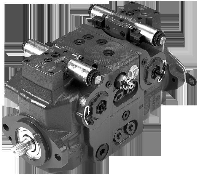

1 Technical Information H1T 045/053/060/068 H1 Axial Piston Tandem Pumps
2 Revision history Table of revisions Date Changed Rev July 2018 Major revision June 2018 Angle sensor chapters added September 2017 add G6 option 0603 June 2017 minor edit page April 2017 add November 2015 Master Model Code changes Various changes. BA-EA Jul 2009 First edition AA 2 Danfoss July 2018 BC en-US0801
3 Contents Technical specifications H1 Pumps General Specification...4 Technical Data for H1 Tandem Pumps... 4 Operating parameters H1 Tandem Pumps... 5 Fluid Specifications...6 External radial shaft loads H1 Tandem... 6 Bearing Life... 7 Mounting flange loads H1T 045/ Mounting flange loads H1T 060/ Case drain...8 Master model code H1 Tandem H1T Master Model Code...9 Control Options Port Locations Dimensions Electrical Displacement Control (EDC) EDC Solenoid Data Manual Displacement Control (MDC)...17 Forward-Neutral-Reverse Control (FNR) Control Response...24 Non Feedback Proportional Electric Control (NFPE) Manual Over Ride (MOR) Swash Plate Angle Sensor for EDC Controls...28 Swash Plate Angle Sensor Parameters (EDC)...28 Swash Plate Angle Sensor Connector Interface with ECU...29 Swash plate angle sensor for NFPE and AC2 controls Swash Plate Angle Sensor Parameters (NFPE/AC) Swash Plate Angle Sensor Connector Interface with ECU...31 Control-Cut-Off (CCO) and Brake Release Valves Displacement limiter...34 Port Locations H1P 045/053 Tandem Port Locations H1P 060/068 Tandem Dimensions H1T 045/053 Tandem Dimensions H1T 060/068 Tandem Input shaft, option G1 (SAE C, 14 teeth) (045/053/060/068)...42 Input shaft, option G5 (SAE B-B, 15 teeth) (045/053 only) Input shaft, option G6, (19 teeth-long) (045/053 only) Input shaft, option F1, (060/068 only) Auxiliary mounting pads /068 Control dimensions /053 Control dimensions Center section coupling, torque rating...61 Control Cut Off (CCO) /053 CCO /068 CCO Displacement limiter, H1 Tandem, option B Danfoss July 2018 BC en-US0801 3
4 Technical specifications H1 Pumps General Specification Axial piston closed circuit variable displacement pump of cradle swash-plate design with clockwise or counterclockwise direction of rotation. Pipe connections Main pressure ports H1P 045/053: SAE straight thread O-ring boss Main pressure ports H1P 060/068: ISO split flange boss Remaining ports: SAE straight thread O-ring boss Recommended installation position Pump installation position is discretionary, however the recommended control position is on the top or at the side with the top position preferred. If the pump is installed with the control at the bottom, flushing flow must be provided through port M14 located on the EDC, FNR and NFPE control. Vertical input shaft installation is acceptable. If input shaft is at the top, 1 bar case pressure must be maintained during operation. The housing must always be filled with hydraulic fluid. Recommended mounting for a multiple pump stack is to arrange the highest power flow towards the input source. Consult Danfoss for nonconformance to these guidelines. Auxiliary cavity pressure Auxiliary cavity pressure will be inlet pressure with internal charge pump or case pressure with external charge supply. For reference see Operating parameters H1 Tandem Pumps on page 5. Please verify mating pump shaft seal capability. Technical Data for H1 Tandem Pumps Feature Unit Size 045 Size 053 Size 060 Size 068 Displacement cm 3 Flow at rated (continuous) speed * Torque at maximum displacement (theoretical) [in 3 ] Mass moment of inertia of rotating components kg m 2 Mass (weight dry, without charge pump or auxiliary flange) l/min [US gal/min] N m/bar [lbf in/1000 psi] [slug ft 2 ] 45.0 [2.75] 153 [40] 0.8 [488] [ ] 53.8 [3.28] 183 [48] 0.9 [549] [ ] 60.4 [3.69] 210 [55.5] 0.96 [590] [ ] kg [lb] 65 [143] 96.2 [212] Oil volume l [US gal] 2.3 [0.61] 4.2 [1.1] Mounting flange per ISO Flange (SAE B), Special bolt diameter Input shaft outer diameter, splines per ISO Outer Ø25 mm - 4 (SAE B-B, 15 teeth) Outer Ø32 mm - 4 (SAE-C, 14 teeth) Outer Ø31 mm - 4 (19 teeth) 68.0 [4.15] 238 [62.8] 1.08 [610] Flange (SAE C) [ ] Outer Ø32 mm - 4 (SAE C, 14 teeth)o uter Ø35 mm - 4 (SAE-C, 21 teeth) 4 Danfoss July 2018 BC en-US0801
5 Technical specifications Feature Unit Size 045 Size 053 Size 060 Size 068 Auxiliary mounting flange with metric fasteners, shaft outer diameter and splines per ISO Charge inlet port per ISO (SAE O-ring boss) Main port configuration Case drain port L3 per ISO (use for cooling purposes) Other ports Customer interface threads * Applies for each rotating group. Flange 82-2: outer Ø16 mm - 4 (SAE A, 9 teeth) outer Ø19 mm - 4 (SAE A, 11 teeth) Flange 101-2: outer Ø22 mm - 4 (SAE B, 13 teeth) outer Ø25 mm - 4 (SAE B-B, 15 teeth) ISO : (SAE O-ring boss) Flange 101-2: outer Ø22 mm - 4 (SAE B, 13 teeth) outer Ø25 mm - 4 (SAE B-B, 15 teeth) ISO 6162: M12 x 1.75 (Split flange) (SAE O-ring boss) (SAE O-ring boss) SAE O-ring boss Metric fasteners Operating parameters H1 Tandem Pumps Feature Size 045 Size 053 Size 060 Size 068 Input speed (at minimum charge/control pressure) Minimum for external charge supply 1) 500 min -1 (rpm) Rated 3400 min -1 (rpm) 3500 min -1 (rpm) Maximum 3500 min -1 (rpm) 4000 min -1 (rpm) System pressure Maximum working pressure 420 bar [6090 psi] 380 bar [5510 psi] 420 bar [6090 psi] 380 bar [5510 psi] Maximum pressure 450 bar [6527 psi] 400 bar [5800 psi] 450 bar [6527 psi] 400 bar [5800 psi] Maximum low loop Minimum low loop pressure 45 bar [650 psi] 10 bar [145 psi] Charge pressure Minimum without CCO valve 16 bar [232 psi] Minimum with CCO valve Maximum 18 bar [265 psi] 34 bar [435 psi] Control pressure Min. at corner power (EDC, MDC, FNR) 21.5 bar [312 psi] 18.5 bar [268 psi] Maximum 40 bar [580 psi] Case pressure Rated 3 bar [44 psi] Maximum Lip seal external maximum pressure 1) Full performance (pressure and displacement) possible at minimum charge and control pressure supply. 5 bar [73 psi] 0.4 [5.8 psi] Danfoss July 2018 BC en-US0801 5
6 Technical specifications Fluid Specifications Viscosity Intermittent 1) Minimum Recommended range Maximum 5 mm 2 /s [42 SUS] 7 mm 2 /s [49 SUS] mm 2 /s [ SUS] 1600 mm 2 /s [7500 SUS] 1) Intermittent = Short term t < 1 min per incident and not exceeding 2 % of duty cycle based load-life Temperature Minimum (cold start) Rated Recommended range * Maximum Intermittent -40 C [-40 F] 104 C [220 F] C [ F] 115 C [240 F] * At the hottest point, normally case drain port Filtration, Cleanliness level and Efficiency β x -ratio ( Recommended Minimum) Cleanliness per ISO /18/13 Efficiency β x (charge pressure filtration) β = 75 (β 10 10) Efficiency β x (suction and return line filtration) β = 75 (β 10 2) Recommended inlet screen mesh size µm External radial shaft loads H1 Tandem External radial shaft loads H1 pumps are designed with bearings that can accept some external radial loads. The external radial shaft load limits are a function of the load position and orientation, and the operating conditions of the unit. External radial shaft loads impact lifetime. For lifetime calculations please contact Danfoss representative. The maximum allowable radial load (R e ) is based on the maximum external moment (M e ) and the distance (L) from the mounting flange to the load. R e = It may be determined using the following formula: M e L Radial load position (045/053 shown) 0 R e L R e 270 R e CCW Rotation CW Rotation 90 R e M e 180 R e P E M e = shaft moment L = flange distance R e = external force to the shaft Thrust loads should be avoided. Contact factory in the event thrust loads are anticipated. 6 Danfoss July 2018 BC en-US0801
7 Technical specifications Bearing Life Maximum external shaft load based on shaft deflection External radial moment Unit Size 045 / 053 Size 060 / 068 M e N m [lbf in] 104 [920] 104 [920] All external shaft loads affect bearing life. In applications with external shaft loads, minimize the impact by positioning the load at 0 or 180 as shown in the figure. Danfoss recommends clamp-type couplings for applications with radial shaft loads. Contact your Danfoss representative for an evaluation of unit bearing life if you have continuously applied external loads exceeding 25 % of the maximum allowable radial load (Re) or the pump swashplate is positioned on one side of center all or most of the time. Mounting flange loads H1T 045/053 H1 tandem pump front flange load Mounting flange loads H1T 045/053, Controls on top M R M S P The moments shown below apply for the control orientation on top or side. Mounting Control on flange top loads, Control on top Mounting flange loads, Control on side Control on side P a Rated moment: M R = 2020 N m [ lbf in] Shock load moment: M S = 4110 N m [ lbf in] P b Rated moment: M R = 1300 N m [ lbf in] Shock load moment: M S = 2930 N m [ lbf in] For more information, see H1 Axial Piston Pumps, Basic Information, BC , the section Mounting flange loads. Danfoss July 2018 BC en-US0801 7
8 Technical specifications Mounting flange loads H1T 060/068 H1 tandem pump front flange load Mounting flange loads H1T 060/068, Controls on top Rated moment: M R = 2190 N m [ lbf in] Shock load moment: M S = 6560 N m [ lbf in] M R M S P The moments shown apply for the control orientation on top or side. For more information, see H1 Axial Piston Pumps, Basic Information, BC , the section Mounting flange loads. Case drain The tandem housings are connected through the center section via a drilled hole. The charge relief valve discharges oil into the front housing. In order to provide positive flow through both housings, use of the rear housing case drain is required. The front housing case pressure ports should only be used if the pump is used as a common drain manifold for the vehicle where external drain flow is brought into the rear housing and discharged out the front. The allowable case pressures must be met accordingly. 8 Danfoss July 2018 BC en-US0801
9 Master model code H1 Tandem H1T Master Model Code Displacement (Front pump, second pump see C ) cm 3 [2.75 in 3 ] cm 3 [3.28 in 3 ] cm 3 [3.66 in 3 ] cm 3 [4.15 in 3 ] A Rotation L Left hand (counter clockwise) R Right hand (clockwise) B Product version A Revision code Z Port configuration A Inch, Customer O-ring port sealing according to ISO C Second pump size N Frame size of rear stage equal front stage (default) A Rear stage kit 45cc/rev (only use with 53cc/rev front stage) B Rear stage kit 60cc/rev (only use with 68cc/rev front stage) D Controls Code Control type Voltage Miscellaneous options Connector A2 EDC 12 V DEUTSCH A3 EDC 24 V DEUTSCH A4 EDC 12 V MOR DEUTSCH A5 EDC 24 V MOR DEUTSCH A9 FNR 12 V MOR DEUTSCH H3 EDC 24 V Angle sensor DEUTSCH H4 MDC front unit Gain 0.52 with NSS FNR rear unit 12 V Gain 0.52 with MOR DEUTSCH H6 EDC 12 V Angle sensor + MOR DEUTSCH H7 EDC 24 V Angle sensor + MOR DEUTSCH B1 FNR 24 V MOR DEUTSCH FNR front unit 12 V DEUTSCH B6 EDC rear unit 12 V Gain 0.52 DEUTSCH D7 EDC front unit 12 V MOR DEUTSCH FNR rear unit 12 V MOR DEUTSCH Danfoss July 2018 BC en-US0801 9
10 Master model code H1 Tandem D Controls (continued) Code Control type Voltage Miscellaneous options Connector D9 MDC front unit Gain 0.52 with NSS MDC rear unit Gain 0.52 DEUTSCH N1 NFPE 1) 12 V MOR DEUTSCH N2 NFPE 1) 24 V MOR DEUTSCH N5 NFPE 1) 12 V Angle sensor + MOR DEUTSCH N6 NFPE 1) 24 V Angle sensor + MOR DEUTSCH M1 MDC M2 MDC NSS 1) Align with options: E: Displacement limiters and W: Special hardware. F Orifices (mm) Code Tank (A+B) P A / B Note C3 No orifice Not to be used for FDC controls and mobile applications. C1 0.8 Not to be used for FDC controls. C6 1 C7 1.3 C C D To be used for MDC controls only. D D D D E Displacement limiter N None C No limiters, with nested springs, required for NFPE B Adjustable externally D Adjustable externally with nested springs, required for NFPE G Endcap options Code Description 045/ /068 E7 Tandem same-sided SAE O-ring boss ports, (HPRV only) standard D1 Tandem same-sided SAE O-ring boss ports with Control Cut Off (HPRV only), 12 V F7 Tandem same-sided SAE O-ring boss ports with Control Cut Off (HPRV only), 24 V H3 Tandem Opp. Port Code 62, 12V CCO & Brake H4 Tandem Opp. Port Code 62, 24V CCO & Brake H5 Tandem Opp. Port Code 62, 12V CCO H6 Tandem Opp. Port Code 62, 24V CCO 10 Danfoss July 2018 BC en-US0801
11 Master model code H1 Tandem G Endcap options (continued) Code Description 045/ /068 H7 Tandem Opp. Port Code 62 H8 Tandem Opp Port Code 62, Opposite Charge Inlet H Mounting F ISO , flange SAE B (045/053) H ISO , flange SAE C (060/068) J ISO , flange SAE B and speed sensor (045/053) J Input shaft Code Description 045/ /068 G1 ISO , outer Ø32 mm - 4 (SAE C, 14 teeth splined shaft 12/24 pitch) G5 ISO , outer Ø25 mm - 4 (SAE B-B, 15 teeth splined shaft 16/32 pitch) G6 ISO , outer Ø31 mm - 4 (19 teeth splined shaft 16/32 pitch) (45/53 only) F1 ISO outer diameter 35mm -4 (SAE C, 21 teeth splined shaft 16/32 pitch) (60/68 only) K Auxiliary mounting pad ISO without charge pump, with shipping cover Code Description 045/ /068 NN No auxiliary mounting pad, No shipping cover H2 Flange 82-2, outer Ø16 mm - 4 (SAE A, 9 teeth 16/32 coupling) (45/53) H1 Flange 82-2, outer Ø19 mm - 4 (SAE A, 11 teeth 16/32 coupling) (45/53) H3 Flange 101-2, outer Ø22 mm - 4 (SAE B, 13 teeth 16/32 coupling) H5 Flange 101-2, outer Ø25 mm - 4 (SAE B-B, 15 teeth 16/32 coupling) Align with options: S Charge pump and Y Special settings. M High pressure relief valve setting, NO bypass, side A (front pump) N High pressure relief valve setting, NO bypass side B (front pump) P High pressure relief valve setting, NO bypass, side C (rear pump) R High pressure relief valve setting, NO bypass, side D (rear pump) Code Pressure setting (Use the selection for ports A, B, C and D) bar [1885 psi] bar [2175 psi] bar [2610 psi] bar [2900 psi] bar [3336 psi] bar [3630 psi] bar [4061 psi] bar [4350 psi] bar [4786 psi] Danfoss July 2018 BC en-US
12 Master model code H1 Tandem M High pressure relief valve setting, NO bypass, side A (front pump) N High pressure relief valve setting, NO bypass side B (front pump) P High pressure relief valve setting, NO bypass, side C (rear pump) R High pressure relief valve setting, NO bypass, side D (rear pump) (continued) Code Pressure setting (Use the selection for ports A, B, C and D) bar [5080 psi] bar [5510 psi] bar [5800 psi] bar [5946 psi] bar [6090 psi] = available option, = not available option Pressure limiter 060/068 Code Pressure setting (Use the selection for ports A, B, C and D) AE 150 bar PL / 200 bar HPRV AH 180 bar PL / 250 bar HPRV BK 200 bar PL / 250 bar HPRV BC 230 bar PL / 280 bar HPRV BE 250 bar PL / 300 bar HPRV BH 280 bar PL / 330 bar HPRV CK 300 bar PL / 350 bar HPRV CC 330 bar PL / 380 bar HPRV CE 350 bar PL / 400 bar HPRV CH 380 bar PL / 430 bar HPRV DK 400 bar PL / 450 bar HPRV - DA 410 bar PL / 450 bar HPRV - DB 420 bar PL / 450 bar HPRV - S Charge pump N No charge pump, external charge supply (Align with options: T Filtration) T Filtration P E Remote full charge flow filtration (045/053 only) External charge filtration (060/068 only) V Charge pressure relief setting bar [261 psi] bar [290 psi] bar [319 psi] bar [348 psi] Not to be used for NFPE controls. 12 Danfoss July 2018 BC en-US0801
13 Master model code H1 Tandem V Charge pressure relief setting (continued) bar [377 psi] bar [406 psi] bar [435 psi] bar [464 psi] bar [493 psi] W Special hardware features PN EDC/FNR/MDC valve plate (without a handle) P1 NFPE valve plate (Align with options: D Control selection and E Displacement limiters) P4 EDC/FNR/MDC Valve Plate and Speed Ring (045/053 only) H1 EDC/FNR/MDC Valve Plate, included MDC Handle (All frames) H2 EDC/FNR/MDC Valve Plate, MDC Handle Front, System Loop Bypass (045/053 only) X Paint and nametag NNN Black paint and Danfoss nametag Y Special settings NNN None M00 MDC (handle in standard position) Danfoss July 2018 BC en-US
14 Control Options Electrical Displacement Control (EDC) The Electrical Displacement Control (EDC) consists of a pair of proportional solenoids on each side of a three-position, four-way porting spool. The proportional solenoid applies a force input to the spool, which ports hydraulic pressure to either side of a double acting servo piston. Differential pressure across the servo piston rotates the swash-plate, changing the pump s displacement from full displacement in one direction to full displacement in the opposite direction. A serviceable 125 μm screen is located in the supply line immediately before the control porting spool. Under some circumstances, such as contamination, the control spool could stick and cause the pump to stay at some displacement. Electrical Displacement Control EDC schematic, feedback from swash-plate M14 C1 C2 F00B F00A Feedback from Swash plate T P P E P EDC Control Signal Requirements Pump displacement vs. control current 100 % Displacement -b -a "0" a Current ma b 100 % 14 Danfoss July 2018 BC en-US0801
15 Control Options EDC Control minimum current to stroke pump Voltage a * b Pin connections 12 V 640 ma 1640 ma any order 24 V 330 ma 820 ma * Factory test current, for vehicle movement or application actuation expect higher or lower value. Connector 1 2 P Connector ordering data Description Quantity Ordering data Mating connector 1 DEUTSCH DT06-2S Wedge lock 1 DEUTSCH W2S Socket contact (16 and 18 AWG) 2 DEUTSCH Danfoss mating connector kit 1 K29657 EDC Solenoid Data Description 12 V 24 V Maximum current 1800 ma 920 ma Nominal coil 20 C [68 F] 3.66 Ω C [176 F] 4.52 Ω Ω Inductance 33 mh 140 mh PWM signal frequency Range Hz Recommended * 200 Hz IP Rating IEC IP 67 DIN , part 9 IP 69K with mating connector Connector color Black * PWM signal required for optimum control performance. Pump output flow direction vs. control signal Shaft rotation CW CCW Front Rear Front Rear Coil energized * C2 C1 C2 C1 C2 C1 C2 C1 Port A in out out in Port B out in in out Port C in out out in Port D out in in out Servo port pressurized * For coil location see Installation drawings. M5 M4 M5 M4 M5 M4 M5 M4 Danfoss July 2018 BC en-US
16 Control Options Control Response H1 controls are available with optional control passage orifices to assist in matching the rate of swashplate response to the application requirements. The time required for the pump output flow to change from zero to full flow (acceleration) or full flow to zero (deceleration) is a net function of spool porting, orifices, and charge pressure. H1 pumps are limited in mechanical orifice combinations. Mechanical servo orifices are to be used only for fail-safe return to neutral in a case of an electrical failure. A swash-plate response times table is available for each frame size. Testing should be conducted to verify the proper orifice selection for the desired response. Typical response times at the following conditions: p = 250 bar [3626 psi] Charge pressure = 20 bar [290 psi] Viscosity and temperature = 30 mm²/s [141 SUS] and 50 C [122 F] Speed = 1800 min -1 (rpm) Response time, EDC 045/053 Stroking direction 0.8 mm [0.03 in] orifice 1.3 mm [0.05 in] orifice No orifice Neutral to full flow 1.7 s 0.9 s 0.5 s Full flow to neutral 1.1 s 0.6 s 0.3 s Response time, EDC 060/068 Stroking direction 0.8 mm [0.03 in] Orifice 1.3 mm [0.05 in] Orifice No orifice Neutral to full flow 2.6 s 1.2 s 0.8 s Full flow to neutral 1.7 s 0.8 s 0.4 s 16 Danfoss July 2018 BC en-US0801
17 Control Options Manual Displacement Control (MDC) A Manual proportional Displacement Control (MDC) consists of a handle on top of a rotary input shaft. The shaft provides an eccentric connection to a feedback link. This link is connected on its one end with a porting spool. On its other end the link is connected the pumps swash-plate. This design provides a travel feedback without spring. When turning the shaft the spool moves thus providing hydraulic pressure to either side of a double acting servo piston of the pump. Differential pressure across the servo piston rotates the swash plate, changing the pump s displacement. Simultaneously the swash-plate movement is fed back to the control spool providing proportionality between shaft rotation on the control and swash-plate rotation. The MDC changes the pump displacement between no flow and full flow into opposite directions. Under some circumstances, such as contamination, the control spool could stick and cause the pump to stay at some displacement. A serviceable 125 μm screen is located in the supply line immediately before the control porting spool. The MDC is sealed by means of a static O-ring between the actuation system and the control block. Its shaft is sealed by means of a special O-ring which is applied for low friction. The special O-ring is protected from dust, water and aggressive liquids or gases by means of a special lip seal. Manual Displacement Control Pump displacement vs. control lever rotation 100 % Displacement -d -b "A" -c -a "0" a Lever rotation d "B" b c P % Legend: Deadband on B side a = 3 ±1 Maximum pump stroke b = 30 +2/-1 Required customer end stop c = 36 ±3 Internal end stop d = 40 P MDC General Information In difference to other controls the MDC provides a mechanical deadband. This is required to overcome the tolerances in the mechanical actuation. The MDC contains an internal end stop to prevent over travel. The restoring moment is appropriate for turning the MDC input shaft back to neutral only. Any linkages or cables may prevent the MDC from returning to neutral. The MDC is designed for a maximum case pressure of 5 bar and a rated case pressure of 3 bar. If the case pressure exceeds 5 bar there is a risk of an insufficient restoring moment. In addition a high case pressure can cause the NSS to indicate that the control is not in neutral. High case pressure may cause excessive wear. Customers can apply their own handle design but they must care about a robust clamping connection between their handle and the control shaft and avoid overload of the shaft. Danfoss July 2018 BC en-US
18 Control Options Customers can connect two MDC s on a tandem unit in such a way that the actuation force will be transferred from the pilot control to the second control but the kinematic of the linkages must ensure that either control shaft is protected from torque overload. To avoid an overload of the MDC, customers must install any support to limit the setting range of the Bowden cable. C Caution Using the internal spring force on the input shaft is not an appropriate way to return the customer connection linkage to neutral. MDC Torque Description Value Torque required to move handle to maximum displacement 1.4 N m [12.39 lbf in ] Torque required to hold handle at given displacement Maximum allowable input torque 0.6 N m [5.31 lbf in] 20 N m [177 lbf in] C Caution Volumetric efficiencies of the system will have impacts on the start and end input commands. MDC Shaft Rotation CCW CW P MDC shaft rotation data Pump shaft rotation * Clock Wise (CW) Counter Clock Wise (CCW) MDC shaft rotation CW CCW CW CCW Port A in (low) out (high) out (high) in (low) Port B out (high) in (low) in (low) out (high) Servo port high pressure M5 M4 M5 M4 * As seen from shaft side. Control Response H1 controls are available with optional control passage orifices to assist in matching the rate of swashplate response to the application requirements. The time required for the pump output flow to change from zero to full flow (acceleration) or full flow to zero (deceleration) is a net function of spool porting, orifices, and charge pressure. H1 pumps are limited in mechanical orifice combinations. Mechanical servo orifices are to be used only for fail-safe return to neutral in a case of an electrical failure. 18 Danfoss July 2018 BC en-US0801
19 Control Options A swash-plate response times table is available for each frame size. Testing should be conducted to verify the proper orifice selection for the desired response. Typical response times at the following conditions: p = 250 bar [3626 psi] Charge pressure = 20 bar [290 psi] Viscosity and temperature = 30 mm²/s [141 SUS] and 50 C [122 F] Speed = 1800 min -1 (rpm) Response time, MDC 045/053 Code Orifice description (mm) Stroking direction (sec) P A B Tank (A+B) Neutral to full flow Full flow to neutral C C C C C D D D D D Response time, MDC 060/068 Code Orifice description (mm) Stroking direction (sec) P A B Tank (A+B) Neutral to full flow Full flow to neutral C C C C C D D D D D Neutral Start Switch (NSS) The Neutral Start Switch (NSS) contains an electrical switch that provides a signal of whether the control is in neutral. The signal in neutral is Normally Closed (NC). Danfoss July 2018 BC en-US
20 Control Options Neutral Start Switch schematic M14 M5 M4 M3 P Neutral Start Switch data Max. continuous current with switching Max. continuous current without switching Max. voltage Electrical protection class 8.4 A 20 A 36 V DC IP67 / IP69K with mating connector Case Gauge Port M14 The drain port should be used when the control is mounted on the unit s bottom side to flush residual contamination out of the control. MDC schematic diagram M14 M5 M4 M3 P Danfoss July 2018 BC en-US0801
21 Control Options Lever MDC controls are available with optional lever/handle. Align with Settings: Y module in the model code. Standard orientation 90 from input shaft P Danfoss July 2018 BC en-US
22 Control Options Forward-Neutral-Reverse Control (FNR) The 3-position FNR control options A9 (12 V) and B1 (24 V) uses an electric input signal to switch the pump to a full stroke position. A serviceable 125 μm screen is located in the supply line immediately before the control porting spool. Forward-Neutral-Reverse electric control (FNR) FNR hydraulic schematic M14 C1 C2 F00B F00A T P P P Pump displacement vs. electrical signal 100 % Displacement 0 Voltage VDC 100 % Under some circumstances, such as contamination, the control spool could stick and cause the pump to stay at some displacement. Control current Voltage 12 V DC 24 V DC Min. current to stroke pump 750 ma 380 ma Pin connections any order 22 Danfoss July 2018 BC en-US0801
23 Control Options Connector 1 2 P Connector ordering data Description Quantity Ordering data Mating connector 1 DEUTSCH DT06-2S Wedge lock 1 DEUTSCH W2S Socket contact (16 and 18 AWG) 2 DEUTSCH Danfoss mating connector kit 1 K29657 Solenoid data Voltage 12 V DC 24 V DC Minimum supply voltage 9.5 V DC 19 V DC Maximum supply voltage (continuous) 14.6 V DC 29 V DC Bi-directional diode cut off voltage 28 V DC 53 V DC Maximum current 1050 ma 500 ma Nominal coil 20 C 8.4 Ω 34.5 Ω PWM Range Hz PWM Frequency (preferred) * 100 Hz IP Rating (IEC ) + DIN IP 67/IP 69K (part 9 with mating connector) * PWM signal required for optimum control performance. Pump output flow direction vs. control signal Shaft rotation CW CCW Front Rear Front Rear Coil energized * C1 C2 C1 C2 C1 C2 C1 C2 Port A in out out in Port B out in in out Port C in out out in Port D out in in out Servo port pressurized * For coil location see installation drawings. M5 M4 M5 M4 M5 M4 M5 M4 Danfoss July 2018 BC en-US
24 Control Options Control Response H1 controls are available with optional control passage orifices to assist in matching the rate of swashplate response to the application requirements. The time required for the pump output flow to change from zero to full flow (acceleration) or full flow to zero (deceleration) is a net function of spool porting, orifices, and charge pressure. H1 pumps are limited in mechanical orifice combinations. Mechanical servo orifices are to be used only for fail-safe return to neutral in a case of an electrical failure. A swash-plate response times table is available for each frame size. Testing should be conducted to verify the proper orifice selection for the desired response. Typical response times at the following conditions: p = 250 bar [3626 psi] Charge pressure = 20 bar [290 psi] Viscosity and temperature = 30 mm²/s [141 SUS] and 50 C [122 F] Speed = 1800 min -1 (rpm) Response Time, FNR Stroking direction Size combo 0.8 [0.03] orifice 1.3 [0.05] orifice No orifice Neutral to full flow 045/ s 0.9 s 0.5 s 060/ s 1.3 s 0.8 s Full flow to neutral 045/ s 0.8 s 0.4 s 060/ s 1.1 s 0.5 s 24 Danfoss July 2018 BC en-US0801
25 Control Options Non Feedback Proportional Electric Control (NFPE) The Non Feedback Proportional Electric (NFPE) control is an electrical automotive control in which an electrical input signal activates one of two proportional solenoids that port charge pressure to either side of the pump servo cylinder. The NFPE control has no mechanical feedback mechanism. A serviceable 170 μm screen is located in the supply line immediately before the control porting spool. Under some circumstances, such as contamination, the control spool could stick and cause the pump to stay at some displacement. Non Feedback Proportional Electric Control NFPE schematic M14 C1 C2 F00B F00A T P P P Control signal requirements, NFPE 045/053 Tandem Control current Voltage a * ma b ma c ma Pin connections 12 V any order 24 V * Factory test current, for vehicle movement or application actuation expect higher or lower value. Connector 1 2 P Connector ordering data Description Quantity Ordering data Mating connector 1 DEUTSCH DT06-2S Wedge lock 1 DEUTSCH W2S Socket contact (16 and 18 AWG) 2 DEUTSCH Danfoss mating connector kit 1 K29657 Danfoss July 2018 BC en-US
26 Control Options Description 12 V 24 V Maximum current 1800 ma 920 ma Nominal coil 20 C [68 F] 3.66 Ω C [176 F] 4.52 Ω Ω Inductance 33 mh 140 mh PWM signal frequency Range Hz Recommended * 200 Hz IP Rating IEC IP 67 DIN , part 9 IP 69K with mating connector Connector color Black * PWM signal required for optimum control performance. Pump output flow direction vs. control signal Shaft rotation CW CCW Coil energized * C1 C2 C1 C2 Port A in out out in Port B out in in out Servo port pressurized M5 M4 M5 M4 * For coil location see Installation drawings. Control Response H1 controls are available with optional control passage orifices to assist in matching the rate of swashplate response to the application requirements. The time required for the pump output flow to change from zero to full flow (acceleration) or full flow to zero (deceleration) is a net function of spool porting, orifices, and charge pressure. H1 pumps are limited in mechanical orifice combinations. Mechanical servo orifices are to be used only for fail-safe return to neutral in a case of an electrical failure. A swash-plate response times table is available for each frame size. Testing should be conducted to verify the proper orifice selection for the desired response. Typical response times at the following conditions: p = 250 bar [3626 psi] Charge pressure = 20 bar [290 psi] Viscosity and temperature = 30 mm²/s [141 SUS] and 50 C [122 F] Speed = 1800 min -1 (rpm) Response Time, NFPE Stroking direction Size combo 0.8 [0.03] orifice 1.3 [0.05] orifice No orifice Neutral to full flow 045/ s 1.2 s 0.8 s 060/ s 1.6 s 1.0 s Full flow to neutral 045/ s 0.7 s 0.4 s 060/ s 0.8 s 0.4 s 26 Danfoss July 2018 BC en-US0801
27 Control Options Manual Over Ride (MOR) All controls are available with a Manual Over Ride (MOR) either standard or as an option for temporary actuation of the control to aid in diagnostics. Forward-Neutral-Reverse (FNR) and Non Feedback Proportional Electric (NFPE) controls are always supplied with MOR functionality. Manual OverRide (MOR) MOR schematic diagram (EDC shown) M14 P C1 C2 F00B Feedback from Swash plate F00A T P P E Unintended MOR operation will cause the pump to go into stroke. The vehicle or device must always be in a safe condition when using the MOR function. (Example: vehicle lifted off the ground) The MOR plunger has a 4 mm diameter and must be manually depressed to be engaged. Depressing the plunger mechanically moves the control spool which allows the pump to go on stroke. The MOR should be engaged anticipating a full stroke response from the pump. W Warning An o-ring seal is used to seal the MOR plunger where initial actuation of the function will require a force of 45 N to engage the plunger. Additional actuation typically require less force to engage the MOR plunger. Proportional control of the pump using the MOR should not be expected. Refer to control flow table for the relationship of solenoid to direction of flow. Danfoss July 2018 BC en-US
28 Control Options Swash Plate Angle Sensor for EDC Controls The angle sensor detects the swash plate position with an accuracy dependent upon the calibration effort done for the application and direction of rotation from the neutral position. At minimum the sensor can be used for forward, neutral and reverse (FNR) detection. The sensor works on the hall-effect technology. The implemented technology is based on a measurement of the magnetic field direction in parallel to the chip surface. This field direction is converted to a voltage signal at the output. Enhanced calibration of the non-linear behavior leads to more exact calculation of the pump swash plate angle. The 4-pin DEUTSCH connector is part of the sensor housing. The swash plate angle sensor is available for all EDC controls for 12 V and 24 V. Swash plate angle vs. output of supply voltage Sensor output, % of supply voltage 100% 90% 80% 70% 60% 50% 40% 30% 20% 10% 0% Swashplate angle Strong magnetic fields in the proximity of the sensor can influence the sensor signal and must be avoided. Contact your Danfoss representative in case the angle sensor will be used for safety functions. Swash Plate Angle Sensor Parameters (EDC) Parameter Minimum Typical Maximum Supply voltage range 4.5 V DC 5 V DC 5.5 V DC Supply protection 18 V DC Pump neutral output (% of supply voltage) 50% Working range (swash plate angle) Required supply current 30 ma Output current signal 9 ma 11 ma Working temperature 40 C 80 C 115 C Protection Class IP rating IEC IP 67 IP rating DIN 40050, part 9 EMC Immunity (ISO ) IP 69K with mating connector 100 V/m 28 Danfoss July 2018 BC en-US0801
29 Control Options Calibration of the sensor output within the software is mandatory. Vehicle neutral thresholds in the software (±0.5 ) are vehicle dependent and must consider different conditions, example: system temperature, system pressure and/or shaft speed. For safety function: If the sensor fails (invalid signal <10% or >90% of supply voltage), it must be sure that the ECU will go into a diagnostic mode and shift into limited mode in order for the driver to take the full control or the mechanical breaks should be activated. Strong magnetic fields in the proximity of the sensor can influence the sensor signal and must be avoided. Swash Plate Angle Sensor Connector DEUTSCH 4-pin connector 4 1 Legend: 1. Ground (GND) 2. Not connected 3. Output signal 1 (SIG 1) 4. Supply (V+) 3 2 Connector order numbers Description Quantity Order number Mating connector DTM06-4S-E Wedge lock WM-4S 1 Socket contact not available Interface with ECU Interface with ECU diagram Supply 100 nf ECU Signal 100 nf 20 kω OUT VCC GND GND Danfoss July 2018 BC en-US
30 Control Options Swash plate angle sensor for NFPE and AC2 controls The angle sensor detects the swash plate angle position and direction of rotation from the zero position. The swash angle sensor works on the AMR sensing technology. Under the saturated magnetic field, the resistance of the element varies with the magnetic field direction. The output signal give a linear output voltage for the various magnet positions in the sensing range. P Swash plate angle vs. output voltage Swashplate angle vs. output voltage (calibrated at 50 C) 5 Signal 1 (nominal) Signal 2 (redundant) Output voltage (V) Swashplate angle P E Swash Plate Angle Sensor Parameters (NFPE/AC) Parameter Minimum Typical Maximum Supply voltage range 4.75 V 5 V 5.25 V Supply protection 28 V Supply current 22 ma 25 ma Output current (Signal 1, 2) 0.1 ma Short circuit output current to supply or GND 1) 7.5 ma 30 Danfoss July 2018 BC en-US0801
31 Control Options Parameter Minimum Typical Maximum Sensitivity 70.0 mv/deg 78.0 mv/deg 85.8 mv/deg Working range (swash plate angle) Correlation between signals 1 and 2 2) 475 mv 500 mv 525 mv 1) Up to duration of 2.5 seconds at 25 C 2) Signal 1 (nominal) is lower than signal 2 (redundant) Swash Plate Angle Sensor Connector DEUTSCH 4-pin connector Pin Legend: 1. Ground (GND) 2. Output Signal 2 (SIG2) Secondary (redundant) 3. Output Signal 1 (SIG1) Primary (nominal) 4. Supply (V+) 3 2 Connector order numbers Description Quantity Order number Mating connector DTM06-4S-E Wedge lock W4S Socket contact (16-18 AWG) K02325 Interface with ECU Interface with ECU schematic V+ E1 0.1uF ECU Sig1 Sig2 E2 340R 340R 5.6 nf E3 340R 340R 5.6 nf VCC Out 1 Gnd VCC Out 2 Gnd Gnd Minimum recommended load resistance is 100 kω. Danfoss July 2018 BC en-US
32 Control Options Control-Cut-Off (CCO) and Brake Release Valves The H1 tandem pumps offer an optional Control-Cut-Off valve integrated into the pump center section and a separate brake release valve allowing the controls to be activated before activating any auxiliary functions. The CCO valve shunts charge pressure from the pump controls allowing the servo springs to de-stroke both pumps. The valve is normally open for fail-safe operation. The solenoid must be energized for the pump to operate. When the machine control circuits energize the CCO solenoid, it connects charge supply from the charge gallery to the pump controls. The 45/53cc tandem also supplies charge pressure to the port X7 for auxiliary operation of devices such as spring applied/pressure released brakes. The control cut off valve also shunts pressure away from port X7. The 60/68 tandem offers a separate brake release valve that operates independently of the CCO valve allowing the controls to be activated before activating any auxiliary functions. When the 60/68 brake valve is deactivated the X7 port shunts to case. CCO schematic 045/053 tandem M14 M14 C1 C2 C1 C2 MB X7 M3 MC L3 F00B F00A F00B F00A M4 CW PTO M5 M5 M4 MA A B E C D MD 32 Danfoss July 2018 BC en-US0801
33 Control Options CCO schematic 060/068 tandem CONTROL SOLENOID C1 CONTROL SOLENOID C2 CONTROL SOLENOID C2 CONTROL SOLENOID C1 1 2 Supply/Ground Ground/Supply M14 Supply/Ground Ground/Supply 1 2 CCO SOLENOID Supply/Ground Ground/Supply 1 2 BRAKE SOLENOID Supply/Ground Ground/Supply Supply/Ground Ground/Supply Supply/Ground Ground/Supply M C1 C2 A MA M3 E MD D C2 C1 flow out B flow out D L3 ccw H1 Tandem M5 M4 B MB X7 C MC M4 M5 L1 P Solenoid data Description 12 V 24 V Minimum supply voltage 9 V DC 18 V DC Maximum supply voltage (continuous) 16 V DC 32 V DC IP Rating IEC IP 67 DIN , part 9 IP 69K with mating connector Pin connector any order For additional information, please contact Danfoss. CCO connector 1 2 Connector ordering data Description Quantity Ordering number Mating connector 1 DEUTSCH DT06-2S Wedge lock 1 DEUTSCH W2S Socket contact (16 and 18 AWG) 2 DEUTSCH Danfoss July 2018 BC en-US
34 Control Options Displacement limiter H1 pumps are designed with optional mechanical displacement (stroke) limiters factory set to max. displacement. The maximum displacement of the pump can be set independently for forward and reverse using the two adjustment screws to mechanically limit the travel of the servo piston down to 50 % displacement. Adjustments under operating conditions may cause leakage. The adjustment screw can be completely removed from the threaded bore if backed out to far. P Displacement change (approximately) Parameter Size 045 Size 053 Size 060 Size Turn of displacement limiter screw Internal wrench size External wrench size Torque for external hex seal lock nut 5.1 cm 3 [0.31 in 3 ] 6.0 cm 3 [0.37 in 3 ] 5.9 cm 3 [0.36 in 3 ] 6.6 cm 3 [0.40 in 3 ] 4 mm 13 mm 23 N m [204 lbf in] For more information, see H1 Axial Piston Pumps, Service Manual, AX , the section Displacement Limiter Adjustment. 34 Danfoss July 2018 BC en-US0801
35 Port Locations Port Locations H1P 045/053 Tandem L3 M5 M4 Lx MB AM3 MC C D A B E M14 M5 M4 M14 MD MA L3 M3 P Mounting flange, shaft and connector surfaces to be paint free. Ports description, ISO Ports Description Sizes A, B, C, D System ports: A, B, C and D; Ø48.5 max. clearance for fitting MA, MB, MC, MD System gauge ports A, B, C and D; Ø28 max. clearance for fitting E Charge filtration inlet port from filter; Ø36 max. clearance for fitting L3, Lx Case drain port; Ø48.5 max. clearance for fitting M3 Charge gauge / constr. port; Ø28 max. clearance for fitting M4, M5 Servo gauge ports; Ø24.5 max. clearance for fitting M14 Case gauge port; Ø21 max. clearance for fitting (EDC, MDC, FNR, NFPE) AM3 Alternate charge pressure port Danfoss July 2018 BC en-US
36 Port Locations Without CCO (Control Cut Off) MB MC With CCO (Control Cut Off) MB MC Mx M14 Mx M14 Mx M5 4x Connector: Deutsch DT04-2P M4 Lx M3 P Mounting flange, shaft and connector surfaces to be paint free. Ports description, ISO Ports Description Sizes A, B, C, D System ports: A, B, C and D; Ø48.5 max. clearance for fitting MA, MB, MC, MD System gauge ports A, B, C and D; Ø28 max. clearance for fitting E Charge filtration inlet port from filter; Ø36 max. clearance for fitting Lx Case pressure port; Ø48.5 max. clearance for fitting M3 / Mx Charge gauge / constr. port; Ø28 max. clearance for fitting M4, M5 Servo gauge ports; Ø24.5 max. clearance for fitting M14 Case gauge port; Ø21 max. clearance for fitting (EDC, MDC, FNR, NFPE) X7 Brake gauge port Please contact Danfoss representative for specific installation drawings. 36 Danfoss July 2018 BC en-US0801
37 Port Locations Port Locations H1P 060/068 Tandem M5 AM3 M4 L1 M5 M3 M4 L2 E D C L2 B A L1 MC MA M14 M14 MB MD P Ports description, ISO Ports Description Size A, B, C, D System ports: A, B, C and D Split flange, M12 x 1.75 MA, MB, MC, MD System gauge ports A, B, C and D E Charge filtration inlet port from filter L3 Case drain port M3 / Mx Charge gauge / constr. port M4, M5 Servo gauge ports M14 Case gauge port; (EDC, MDC, FNR, NFPE) X7 Brake gauge port Danfoss July 2018 BC en-US
38 Dimensions Dimensions H1T 045/053 Tandem ±1.0 [4.35 ±0.04] ±1.0 [3.94 ±0.04] 89.0 ±1.0 [3.5 ±0.04] 2x 74.4 ±1.0 [2.93 ±0.04] Z ±1.0 [2.08 ±0.04] 39.5 ±1.0 [1.56 ±0.04] 3.35 ±1.0 [0.13 ±0.04] max. [15.98] ±1.0 [13.49 ±0.04] max. [15.41] A A ±1.0 [9.74 ±0.04] both sides ±1.0 [8.22 ±0.04] ±1.0 [6.88 ±0.04] ±1.0 [6.61 ±0.04] ±1.0 [5.36 ±0.04] both sides C C B B 41.0 ±1.0 [1.61 ±0.04] 19.8 ±2.1 [0.78 ±0.083] [ ] 45 ±5 R 0.8 max. [0.031] 1.0 ±0.5 [0.04 ±0.02] [ ] A-A (4x) 85.5 ±1.0 [3.37 ±0.04] Shaft Lc B-B 91.2 ±1.0 [3.59 ±0.04] Shaft Lc C-C 85.5 ±1.0 [3.37 ±0.04] Shaft Lc P L3 case drain port must be used (see the section Case drain on page 8 for more details). Please contact Danfoss representative for specific installation drawings. 38 Danfoss July 2018 BC en-US0801
39 Dimensions ( ) 206 ± ± 0.8 D 2x 14.5 ±0.7 a 5.0 ± 0.3 2x ± ± ± ±1.2 ( 193 ) a 2x 75 ± ±1.0 Shaft lc 37.5 ±0.8 4x 64.2 ± ± ±0.3 ( 37 ) D 2x 25.0 ± ± 3 b D-D 58 ± ± ± ± ±1.0 P Notes in the drawing: a Approximate center of gravity b Lifting holes weight limit not to exeed 75 kg [165 lb] Please contact Danfoss representative for specific installation drawings. Danfoss July 2018 BC en-US
40 Dimensions MD 380 ± ± ±1.2 MA 2x 25 ± ± 0.8 E E CCW CW 2x x 73.0 ±0.25 E-E M12 x H Thd. 18 min. 84 ± 0.8 P Mounting bolt holes are sized for 14 mm fasteners. M12 or ½ inch can be used, but require a hardened washer. Please contact Danfoss representative for specific installation drawings. 40 Danfoss July 2018 BC en-US0801
41 Dimensions Dimensions H1T 060/068 Tandem ± ± ± ± ± ± ±1.2 (2x) ±1.2 (2x) ±1.2 (2x) ±1.2 (2x) ±1.2 (2x) 13.9 ±0.25 (4x) ±1.2 (2x) 71.8 ± ±0.25 (4x) ±0.25 (65) 75 ±0.8 (2x) 75 ±0.8 (2x) 65 (2x) 110 ±0.8 (145.4) ±1.2 (4x) 117 ±0.8 (4x) 110 ± ±0.8 (179.2) (192.5) ±1.2 (2x) 13.9 ±0.25 (4x) 28.6 ±0.25 (4x) 28.6 ±0.25 (4x) ±1.2 (242.5) (255.7) ±1.2 (255.7) (2x) ±1.2 (197.2) (2x) 69.2 ± ± (4x) 60 ± ± ± ±0.8 System ports System ports C and D A and B 60 ±0.8 (2x) ± ±1.2 Danfoss July 2018 BC en-US
42 Dimensions Input shaft, option G1 (SAE C, 14 teeth) (045/053/060/068) Option G ±0.68 [1.89 ±0.03] Mounting flange surface Flange per ISO to be paint free Ø31.58 ±0.08 [1.24 ±0.003] Spline data Number of teeth : 14 Pitch fraction : 12/24 Pressure angle : 30 Pitch-Ø : [1.167] Typ of fit : Fillet root side per : Ansi B92.1b class 6e Ø25.84 max. [1.02] 8.0 ±0.8 [0.31 ±0.03] 30.6 ±0.15 [1.2 ±0.01] Coupling must not protrude beyond this point Specifications Option Spline Min. active spline length 1) G1 14 teeth, 12/24 pitch 30.6 mm [1.205 in] Torque rating 2) Rated 534 N m [4720 lbf in] Maximum 1) Minimum active spline length for the specified torque ratings. 592 N m [5240 lbf in] 2) For definitions of maximum and rated torque values, refer to Basic Information , section Shaft Torque Ratings and Spline Lubrication. 42 Danfoss July 2018 BC en-US0801
43 Dimensions Input shaft, option G5 (SAE B-B, 15 teeth) (045/053 only) Option G ±0.68 [1.5 ±0.03] Mounting flange surface Flange per ISO to be paint free Ø25.23 ±0.08 [0.99 ±0.003] Spline data Number of teeth : 15 Pitch fraction : 16/32 Pressure angle : 30 Pitch-Ø : [0.938] Typ of fit : Fillet root side per : Ansi B92.1b class 6e Ø22.62 max. [0.89] 8.0 ±0.8 [0.31 ±0.03] 22.0 ±0.15 [0.87 ±0.01] Coupling must not protrude beyond this point Specifications Option Spline Min. active spline length 1) G5 15 teeth, 16/32 pitch 22 mm [0.866 in] Torque rating 2) Rated 277 N m [2450 lbf in] Maximum 1) Minimum active spline length for the specified torque ratings. 370 N m [3270 lbf in] 2) For definitions of maximum and rated torque values, refer to Basic Information , section Shaft Torque Ratings and Spline Lubrication. Danfoss July 2018 BC en-US
44 Dimensions Input shaft, option G6, (19 teeth-long) (045/053 only) Option G6, 045/ ±0.68 Spline data Number of teeth : 19 Pitch fraction : 16/32 Pressure angle : 30 Pitch : Type of fit : Fillet root side Per : ANSI B92.1b CLASS 6e 27.7 ± ± ±0.15 Paint free ±0.09 Mating couling must not protrude beyond this point Mounting flange Flange Per ISO (SAE J744 B) 74.3 min. dia. for coupling clearance Specifications Option Spline Min. active spline length 1) G6 19 teeth, 16/32 pitch 34.8 mm [1.370 in] Torque rating 2) Rated 563 N m [4980 lbf in] Maximum 1) Minimum active spline length for the specified torque ratings. 732 N m [6478 lbf in] 2) For definitions of maximum and rated torque values, refer to Basic Information , section Shaft Torque Ratings and Spline Lubrication. 44 Danfoss July 2018 BC en-US0801
45 Dimensions Input shaft, option F1, (060/068 only) Option F1, ISO , outer dia 32 mm-4 (SAE C, 21 teeth) 48 ±0.5 Spline data Number of teeth : 21 Pitch fraction : 16/32 Pressure angle : 30 Pitch : Type of fit : Fillet root side Per : ANSI B CLASS 6 31 ± ±0.15 Paint free 29.4 ± max coupling diameter 8 ±0.8 Mating couling must not protrude beyond this point Flange Mounting flange Per ISO (SAE C) P Specifications Option Spline Min. active spline length 1) F1 21 teeth, 16/32 pitch 31.5 mm [1.358 in] Torque rating 2) Rated 760 N m [6730 lb in] Maximum 1) Minimum active spline length for the specified torque ratings N m [10060 lb in] 2) For definitions of maximum and rated torque values, refer to Basic Information , section Shaft Torque Ratings and Spline Lubrication. Danfoss July 2018 BC en-US
H1 Axial Piston Tandem Pumps Size 045/053/060/068
 Technical Information H1 Axial Piston Tandem Pumps Size 045/053/060/068 powersolutions.danfoss.com Revision history Table of revisions Date Changed Rev September 2017 add G6 option 0603 June 2017 minor
H1 Axial Piston Tandem Pumps Size 045/053
 MAKING MODERN LIVING POSSIBLE Technical Information H1 Axial Piston Tandem Pumps Size 045/053 powersolutions.danfoss.com Revision history Table of revisions Date Changed Rev November 2015 Master Model
H1 Axial Piston Single Pumps Size 045/053
 Technical Information H1 Axial Piston Single Pumps Size 045/053 www.danfoss.com Revision history Table of revisions Date Changed Rev May 2018 Major revision. 1101 May 2017 NFPE gen. 3 changes. 1001 November
H1 Axial Piston Single Pumps Size 147/165
 H1 Axial Piston Single Pumps Size 147/165 www.danfoss.com Revision history Table of revisions Date Changed Rev September 2018 MMC update for M option added. 0802 May 2018 Angle sensor for EDC; FDC note
H1 Axial Piston Single Pumps Size 147/165
 Technical Information H1 Axial Piston Single Pumps Size 147/165 powersolutions.danfoss.com Revision history Table of revisions Date Changed Rev May 2017 NFPE gen. 3 changes. 0701 November 2015 Master Model
H1 Axial Piston Single Pumps Size 147/165
 MAKING MODERN LIVING POSSIBLE Technical Information H1 Axial Piston Single Pumps Size 147/165 powersolutions.danfoss.com Revision history Table of revisions Date Changed Rev September 2014 MDC, CCO, and
H1 Axial Piston Single Pumps Size 045/053
 MAKING MODERN LIVING POSSIBLE Technical Information H1 Axial Piston Single Pumps Size 045/053 powersolutions.danfoss.com Revision history Table of revisions Date Changed Rev August 2015 Master model code
H1 Axial Piston Single Pumps Size 089/100
 MAKING MODERN LIVING POSSIBLE Technical Information H1 Axial Piston Single Pumps Size 089/100 powersolutions.danfoss.com Revision history Table of revisions Date Changed Rev September 2014 MDC, CCO, and
T1P Transit Mixer Axial Piston Pump Size 069/089
 Technical Information T1P Transit Mixer Axial Piston Pump Size 069/089 powersolutions.danfoss.com Revision history Table of revisions Date Changed Rev May 2016 Updated to Engineering Tomorrow design. 0201
H1 Axial Piston Pump Size 115/130, Single. Technical Information
 H1 Axial Piston Pump Size 115/130, Single Technical Information Revisions Revision History Table of revisions Date Page Changed Rev 30 Jul, 2009 First edition AA Jun, 2010 4-6, 12, 14, New EC directive
H1 Axial Piston Pump Size 045/053, Single. Technical Information
 H1 Axial Piston Pump Size 045/053, Single Technical Information Revisions Revision History Table of revisions Date Page Changed Rev 30 Jul, 2009 First edition AA Feb 2010 various 14 teeth added BA Jun,
MP1 Axial Piston Pumps Size 28/32, 38/45
 Technical Information MP1 Axial Piston Pumps Size 28/32, 38/45 www.danfoss.com Revision history Table of revisions Date Changed Rev May 2018 add 14 tooth shaft, minor edits 0106 March 2018 update MDC control
H1 Axial Piston Pump Size 147/165, Single
 MAKING MODERN LIVING POSSIBLE Technical Information H1 Axial Piston Pump Size 147/165, Single powersolutions.danfoss.com Revision History Table of Revisions Date Changed Rev Mar 2014 Converted to Danfoss
H1 Axial Piston Pump Size 147/165, Single. Technical Information
 H1 Axial Piston Pump Size 147/165, Single Technical Information Revisions Revision History Table of revisions Date Page Changed Rev 30 Jul, 2009 First edition AA Jul, 2010 4-6, 10, 12-13 New EC directive
MP1 Axial Piston Pumps Size 28/32, 38/45
 Technical Information MP1 Axial Piston Pumps Size 28/32, 38/45 powersolutions.danfoss.com Revision history Table of revisions Date Changed Rev August 2016 First Edition 0101 2 Danfoss August 2016 BC00000352en-US
Variable Displacement Pumps MP1
 Service Manual Variable Displacement Pumps powersolutions.danfoss.com Revision history Table of revisions Date Changed Rev January 2018 update control current table 0106 November 2017 Add NFPE 0105 October
H1 Axial Piston Pumps Single and Tandem
 Basic Information H1 Axial Piston Pumps Single and Tandem powersolutions.danfoss.com Revision history Table of revisions Date Changed Rev April 2017 NFPE and AC controls added. 0602 May 2016 Updated to
Closed Circuit Axial Piston Pumps H1 45/53/60/68 Tandem
 Service Manual Closed Circuit Axial Piston Pumps H1 45/53/60/68 Tandem www.danfoss.com Revision history Table of revisions Date Changed Rev June 2018 add angle sensor topics 0303 August 2017 minor edits
Technical Information Series 45 G Frame powersolutions.danfoss.com
 MAKING MODERN LIVING POSSIBLE Technical Information Series 45 G Frame powersolutions.danfoss.com Contents Frame G Design... 4 Specifications... 5 Performance G74B... 6 Performance G9C... 7 Order code...
Closed Circuit Axial Piston Pumps H1-045/053/060/068
 Service Manual Closed Circuit Axial Piston Pumps H1-045/053/060/068 www.danfoss.com Revision history Table of revisions Date Changed Rev April 2018 add EDC with angle sensor 0303 September 2014 add MDC
Series 90 Axial Piston Motors. Technical Information
 Series 90 Axial Piston Motors Technical Information HISTORY OF REVISIONS Table of Revisions Date Page Changed Rev. Fourth edition 2 520L0604 Contents GENERAL DESCRIPTION Cross section Cross section Cross
Series 90 Axial Piston Pumps. Technical Information
 Series 90 Axial Piston Pumps Technical Information Revisions History of Revisions Table of Revisions Date Page Changed Rev. March 2010 Various Fix O-ring dimensions in dimension drawings FE December 2009
Series 90 Axial Piston Pumps. Technical Information
 Series 90 Axial Piston Pumps Technical Information Revisions History of Revisions Table of Revisions Date Page Changed Rev. July 2011 35 Typo, 45cc should be 42cc GB July 2011 all Major update GA August
Axial piston variable pump A4VG Series 32. Europe. RE-E Edition: Replaces:
 Axial piston variable pump A4VG Series 32 Europe RE-E 92003 Edition: 04.2016 Replaces: 06.2012 High-pressure pump for applications in a closed circuit Size 28 to 125 Nominal pressure 400 bar Maximum pressure
Series 20 Axial Piston Pumps. Technical Information
 Series 20 Axial Piston Pumps Technical Information General Description INTRODUCTION Sauer-Danfoss a world leader in hydraulic power systems has developed a family of axial piston pumps. DESCRIPTION Sauer-Danfoss
Axial Piston Variable Pump AA4VG
 Electric Drives and Controls Hydraulics Linear Motion and Assembly Technologies Pneumatics Service Axial Piston Variable Pump AA4VG RA 92003-A/06.09 1/64 Replaces: 03.09 Data sheet Series 32 Size 28...
Series 20 Axial Piston Pumps. Technical Information
 Series 20 Axial Piston Pumps Technical Information General Description INTRODUCTION Sauer-Danfoss a world leader in hydraulic power systems has developed a family of axial piston pumps. DESCRIPTION Sauer-Danfoss
Series 90 Axial Piston Pumps. Technical Information
 Series 90 Axial Piston Pumps Technical Information Using this manual ORGANIZATION AND HEADINGS To help you quickly find information in this manual, the material is divided into sections, topics, subtopics,
Series 90 Axial Piston Pumps
 MAKING MODERN LIVING POSSIBLE Series 90 Axial Piston Pumps powersolutions.danfoss.com Revision History Table of Revisions Date Changed Rev March 2014 corrections to pin assignments - page 48 FB February
H1 Bent Axis Variable Displacement Motors Frame Size 080 Frame Size 110. Technical Information
 H1 Bent Axis Variable Displacement Motors Frame Size 080 Frame Size 110 Technical Information Revisions History of Revisions Table of revisions Date Page Changed Rev. 1 Dec, 2008 Different pages New frame
Closed Circuit Axial Piston Pumps H1 115/130 cc
 MAKING MODERN LIVING POSSIBLE Conversion Manual Closed Circuit Axial Piston Pumps H1 115/130 cc powersolutions.danfoss.com Revision history Table of revisions Date Changed Rev December 2015 First edition
Axial Piston Pumps H1-069/078, 089/100, 115/130, 147/165, 210/250
 Service Manual Axial Piston Pumps H1-069/078, 089/100, 115/130, 147/165, 210/250 www.danfoss.com Revision history Table of revisions Date Changed Rev May 2018 add angle sensor 0308 January 20187 add seal
TPV Variable Displacement Closed Loop System Axial Piston Pump THE PRODUCTION LINE OF HANSA-TMP HT 16 / M / 852 / 0815 / E
 HYDRAULIC COMPONENTS HYDROSTATIC TRANSMISSIONS GEARBOXES - ACCESSORIES Certified Company ISO 9001-14001 ISO 9001 Via M. L. King, 6-41122 MODENA (ITALY) Tel: +39 059 415 711 Fax: +39 059 415 729 / 059 415
Series 45 Axial Piston Open Circuit Pumps Technical Information
 Design Frame E cross section LS control (attached to endcap) LS spool PC spool LS adjustment PC adjustment Adjustable displacement limiter Lifting lug Displacement piston guide Displacement piston Slipper
P90 VARIABLE DISPLACEMENT PUMP T E C H N I C A L C A T A L O G
 P90 VARIABLE DISPLACEMENT PUMP T E C H N I C A L C A T A L O G Variable displacement pump POCLAIN HYDRAULICS Design Slider block Swashplate hold-down Servo piston Servo arm Piston Slipper Displacement
Series 40 Axial Piston Motors
 Technical Information powersolutions.danfoss.com Revision history Table of revisions Date Changed Rev February 2017 Corrected document formatting 0703 October 2016 Minor updates 0702 January 2014 Danfoss
Series 45 Axial Piston Open Circuit Pumps Technical Information Frame F
 Design cross section LS contro l (attached to endcap) LS spoo l LS adjustmen t PC spoo l PC adjustmen t Servo piston Bias sprin g Piston Slipper Tapered roller bearing Valve plate Shaft seal Cylinder block
Series 40 Pumps Model Code Supplement Variable pumps model code
 odel Code Supplement Single pump model code Product A B C D E F G H J K L 1 2 3 N P 1 2 S T P Product series Code Description P Series 40 variable pump A Displacement 025 24.6 cm³/rev [1.50 in³/rev] 035
Series 42 4T Axial Piston Tandem Pumps
 Technical Information Series 42 4T Axial Piston Tandem Pumps powersolutions.danfoss.com Revision history Table of revisions Date Changed Rev June 2016 converted to new layout 0101 May 2015 Converted to
Axial Piston Pumps Series 40 M46
 Technical Information Axial Piston Pumps Series 40 M46 powersolutions.danfoss.com Revision history Table of revisions Date Changed Rev March 2017 Minor updates - FNR Control options 0209 October 2016 Minor
Axial Piston Variable Pump A4VG
 Electric Drives and Controls Hydraulics Linear Motion and Assembly Technologies Pneumatics Service Axial Piston Variable Pump A4VG RE 92003/03.09 1/64 Replaces: 09.07 Data sheet Series 32 Sizes 28...250
Series TMM Axial Piston Motor. Technical Information
 Series TMM Axial Piston Motor Technical Information General Description GENERAL DESCRIPTION These motors are designed primarily to be combined with other products in closed circuit systems to transfer
DDC20 Axial Piston Variable Displacement Pump
 Technical Information DDC20 Axial Piston Variable Displacement Pump powersolutions.danfoss.com Revision history Table of revisions Date Changed Rev February 2017 Change charge pump housing 0102 January
P90 VARIABLE DISPLACEMENT PUMP T E C H N I C A L C A T A L O G
 P90 VARIABLE DISPLACEMENT PUMP T E C H N I C A L C A T A L O G Variable displacement pump POCLAIN HYDRAULICS Design Piston Slipper Slider block Servo piston Servo arm Displacement control Feedback linkage
AXIAL PISTON PUMPS SHPV SECTIONAL VIEW
 AXIAL PISTON PUMPS SHPV SECTIONAL VIEW 2 SYSTEM CIRCUIT PUMP AND MOTOR CIRCUIT working loop (high pressure) working loop (low pressure) control fluid suction line case drain fluid Above figure shows schematically
Distribuíção, revenda emanutenção. CatálogosOnline. (11) (11)
 (11)") Distribuíção, revenda emanutenção CatálogosOnline (11)4174-3300-(11)4765-6775 www.hmc.com.br MAKING MODERN LIVING POSSIBLE Technical Information Axial Piston Pumps Series 20 powersolutions.danfoss.com
Distribuíção, revenda emanutenção CatálogosOnline (11)4174-3300-(11)4765-6775 www.hmc.com.br MAKING MODERN LIVING POSSIBLE Technical Information Axial Piston Pumps Series 20 powersolutions.danfoss.com
PM50 VARIABLE DISPLACEMENT PUMP CLOSED LOOP CIRCUIT T E C H N I C A L C A T A L O G
 PM50 VARIABLE DISPLACEMENT PUMP CLOSED LOOP CIRCUIT T E C H N I C A L C A T A L O G PM50 - Variable displacement pump POCLAIN HYDRAULICS OVERVIEW PM50 is a variable displacement, axial piston pump, with
Series 42 Closed Circuit Axial Piston Pumps
 Technical Information Series 42 Closed Circuit Axial Piston Pumps www.danfoss.com Revision history Table of revisions Date Changed Rev August 2018 Minor Update 0103 December 2016 Minor Update 0102 June
TPV Variable Displacement Closed Loop System Axial Piston Pump THE PRODUCTION LINE OF HANSA-TMP HT 16 / M / 851 / 0813 / E
 HYDRAULIC COMPONENTS HYDROSTATIC TRANSMISSIONS GEARBOXES - ACCESSORIES THE PRODUCTION LINE OF HANSA-TMP Variable Displacement Closed Loop System CONTENTS General Information... Order Code... Manual Control
Series 40 Direct Displacement Pumps
 Technical Information powersolutions.danfoss.com Revision history Table of revisions Date Changed Rev July 2017 Removed outdated images 0703 January 2017 Minor updates 0702 July 2015 Minor edits 0701 February
Axial piston variable pump A4VG Series 40
 Axial piston variable pump A4VG eries 40 RE 92004 Edition: 07.2016 Replaces: 06.2012 High-pressure pump for applications in a closed circuit up to 500 bar ize 110...280 Nominal pressure 450 bar Maximum
H1 Bent Axis Motors Size 060/080/110/160/210/250
 Technical Information H1 Bent Axis Motors Size 060/080/110/160/210/250 powersolutions.danfoss.com Revision history Table of revisions Date Changed Rev March 2018 Model code and ports update. 1108 February
Series 45 Axial Piston Open Circuit Pumps. Technical Information
 Series 45 Axial Piston Open Circuit Pumps Technical Information Revisions History of Revisions Table of Revisions Date Page Changed Rev. September 28 58-62 dimension changes for Frame J FJ June 28 78,
Series 42 Axial Piston Pumps. Technical Information
 Series 42 Axial Piston Pumps Technical Information Revisions History of Revisions Table of Revisions Date Page Changed Rev. October 2009 59 Connector/Spool: 6=MS, high gain spool CC October 2009 8, 11
Axial Piston Variable Double Pump A8VO
 Axial Piston Variable Double Pump A8VO RE 93010/03.09 1/40 Replaces: 11.07 Data sheet Series 61 / 63 Sizes 55...200 Nominal pressure 350 bar Peak pressure 400 bar for open circuit Contents Ordering Code
Heavy Duty Hydrostatic Transmissions
 Heavy Duty Hydrostatic Transmissions Features and Benefits Typical Applications Construction Transit Mixer Road Roller Paver Motor Grader Loader Dozer Material Handling & Utility Crane Sweeper Lift Truck
Variable Displacement Pump A4VG for closed circuits
 RE 92 003/05.99 RE 92 003/05.99 replaces: 02.98 Variable Displacement Pump A4VG for closed circuits Sizes 28...250 Series 3 Nominal pressure 400 bar Peak pressure 450 bar A4VG...EP Index Features 1 Ordering
Series 2 Variable Displacement Piston Pump
 Series 2 Variable Displacement Piston Pump ACL 64-105cm 3 /r (3.9-6.4in 3 /r) 2 eaton Series 2 Variable Displacement Piston Pump E-PUPI-MC004-E1 January 2010 Series 2 Variable Displacement Piston Pump
Series T90 Transit Mixer Drive System
 MAKING MODERN LIVING POSSIBLE Technical Information Series T90 Transit Mixer Drive System powersolutions.danfoss.com Contents Series T90 Transit Mixer Drive Transit Mixer Pump Series T90 General Description...
Axial piston variable pump A4VG Series 40
 Axial piston variable pump A4VG eries 40 RE 92004 Edition: 02.2017 Replaces: 07.2016 High-pressure pump for applications in a closed circuit up to 500 bar ize 110...280 Nominal pressure 450 bar Maximum
4T Axial Piston Pumps. Technical Information
 4T Axial Piston Pumps Technical Information Using this manual ORGANIZATION AND HEADINGS To help you quickly find information in this manual, the material is divided into sections, topics, subtopics, and
Axial piston variable pump A4VG Series 40. Americas. RE-A Edition: Replaces:
 Axial piston variable pump A4VG eries 40 Americas RE-A 92004 Edition: 09.2017 Replaces: 06.2012 High-pressure pump for applications in a closed circuit up to 7250 psi (500 bar) ize 110 280 Nominal pressure
Axial Piston Variable Pump A4VG
 Axial Piston Variable Pump A4VG RE 92003/06.09 1/64 Replaces: 03.09 Data sheet Series 32 Sizes 28...250 Nominal 400 bar Peak 450 bar Closed circuit Contents Ordering Code / Standard Program 2 Technical
MCV106A. Hydraulic Displacment Control-PV DESCRIPTION FEATURES ORDERING INFORMATION. BLN Issued: March 1991
 DESCRIPTION MCV106A Hydraulic Displacment Control-PV Issued: March 1991 The MCV106A Hydraulic Displacement Control (HDC) is a costeffective hydraulic pump stroke control which uses mechanical feedback
Series 45 Frame J Axial Piston Open Circuit Pumps. Technical Information
 Series 45 Frame J Axial Piston Open Circuit Pumps Technical Information Using this manual ORGANIZATION AND HEADINGS To help you quickly find information in this manual, the material is divided into sections,
D1 High Power Open Circuit Pumps Size 130/145/193/260
 Technical Information D1 High Power Open Circuit Pumps Size 130/145/193/260 Available only for APAC / EU regions powersolutions.danfoss.com Revision history Table of revisions Date Changed Rev January
AXIAL PISTON PUMPS AND MOTORS
 HPV-HMF SERIES SECTIONA VIEW AXIA PISTON VARIABE DISPACEMENT PUMP AXIA PISTON FIXED DISPACEMENT MOTOR Purge relief valve High pressure relief valves (adjustable) Cylinder block assembly Shaft seal Output
TPV Variable Displacement Closed Loop System Axial Piston Pump HY-TRANS THE PRODUCTION LINE OF HANSA-TMP HT 16 / M / 501 / 1009 / E
 HYDRAULIC COMPONENTS HYDROSTATIC TRANSMISSIONS GEARBOXES - ACCESSORIES HY-TRANS THE PRODUCTION LINE OF HANSA-TMP Via M. L. King, 6-41122 MODENA (ITALY) Tel: +39 059 415 711 Fax: +39 059 415 729 / 059 415
Produktová rada MP1. Miroslav Chmatil.
 Produktová rada MP1 Miroslav Chmatil www.powersolutions.danfoss.com 28/32cc 38/45cc 11x male pistons MP1 Pump Initial Option Portfolio (IOP) Feature Details Mounting Flange SAE B, 2 bolt Input Shafts 13T,
Transit Mixer Axial Piston Pump Size 070/089
 Service Manual Transit Mixer Axial Piston Pump Size 070/089 powersolutions.danfoss.com Revision history Table of revisions Date Changed Rev July 2017 Updated to Engineering Tomorrow 0203 Mar 2014 Converted
Series 45 Open Circuit Axial Piston Pumps. Technical Information. Displacement Piston. Swashplate. Piston. Tapered Roller Bearing
 Series 45 Open Circuit Axial Piston Pumps Technical Information Displacement Piston Piston Swashplate Tapered Roller earing Tapered Roller earing Valve Plate Cylinder lock Kit Shaft Seal General Description
Variable Plug-in Motor A6VE
 Variable Plug-in Motor 6VE RE 91616/01.12 1/52 Data sheet Series 71 Sizes 60 to 170 Nominal pressure 450 bar Maximum pressure 500 bar Open and closed circuits Contents Ordering code for standard program
AXIAL PISTON MOTORS SHMF
 SECTIONAL VIEW Purge relief valve High pressure relief valves (adjustable) Cylinder block assembly Shaft seal Output shaft Valve block Shuttle valve Swashplate 2 SYSTEM CIRCUIT PUMP AND MOTOR CIRCUIT working
PMV0 VARIABLE DISPLACEMENT PUMP CLOSED LOOP CIRCUIT T E C H N I C A L C A T A L O G
 PMV0 VARIABLE DISPLACEMENT PUMP CLOSED LOOP CIRCUIT T E C H N I C A L C A T A L O G PMV0 - Variable displacement pump POCLAIN HYDRAULICS OVERVIEW PMV0 is a variable displacement, axial piston pump, with
Transit Mixer Axial Piston Motor Size 070/084/089
 Technical Information Transit Mixer Axial Piston Motor Size 070/084/089 powersolutions.danfoss.com Revision history Table of revisions Date Changed Rev June 2017 Update to Engineering Tomorrow 0202 Mar
Eaton Fixed Displacement HHD Motor and Variable ACA Pump
 Eaton Fixed Displacement HHD Motor and Variable ACA Pump www.hydpump.com Pump Eaton 3923 4623 5423 6423 7620 7640 Motor Eaton 3933 4633 5433 6433 7630 Eaton ACA Pump Technical Data Table of values (theoretical
H1B 060/080/110/160/210/250 H1 Bent Axis Motors
 H1B 060/080/110/160/210/250 H1 Bent Axis Motors www.danfoss.com Revision history Table of revisions Date Changed Rev August 2018 update adjustment chapter 0504 April 2018 Major layout update, QF080 to
Axial piston variable pump A4VG Series 40
 Axial piston variable pump A4VG eries 40 RE 92004 Edition: 09.2017 Replaces: 02.2017 High-pressure pump for applications in a closed circuit up to 500 bar ize 110 280 Nominal pressure 450 bar Maximum pressure
Series 40 Axial Piston Motors. Technical Information
 Series 40 Axial Piston Motors Technical Information Revisions Revisions Table of Revisions Date Page Changed Rev. November 2007 31 correction to maximum torque rating 15 and 19 tooth FB April 2007 29 Revised
Variable Plug-In Motor A6VE
 Electric Drives and Controls Hydraulics Linear Motion and Assembly Technologies Pneumatics Service Variable Plug-In Motor A6VE RE 91 606/10.07 1/16 Replaces: 06.05 Technical data sheet Series 6 Size Nominal
AXIAL PISTON PUMPS SHPV SECTIONAL VIEW
 AXIAL PISTON PUMPS SHPV SECTIONAL VIEW 2 AXIAL PISTON PUMPS SHPV SYSTEM CIRCUIT PUMP AND MOTOR CIRCUIT working loop (high pressure) working loop (low pressure) control fluid suction line case drain fluid
L and K Frame Variable Motors. Technical Information
 L and K Frame Variable Motors Technical Information Revisions Revisions Table of Revisions Date Page Changed Rev. April 2008 6 corrected the schematic drawings BE January 2008 17 removed displacement limiter
Vickers. Vane Pumps. Double Thru-drive Vane Pumps. High speed, high pressure VQT Series for mobile equipment. Released 7/93
 Vickers Vane Pumps Double Thru-drive Vane Pumps High speed, high pressure VQT Series for mobile equipment Released 7/93 612 Introduction Double VQT high performance pumps are fixed displacement units that
Technical Information Series 45 H Frame powersolutions.danfoss.com
 MAKING MODERN LIVING POILE Technical Information eries 45 H Frame powersolutions.danfoss.com Contents Frame H Design... 4 pecifications... 5 Performance H57... 6 Performance H75D... 7 Order code... 8 Controls...
Medium Duty Piston Pump Variable Displacement Closed Circuit
 Medium Duty Piston Pump Variable Displacement Closed Circuit Model 70160 Model 70360 Model 72400 20.3 cm 3 /r [1.24 in 3 /r] 40.6 cm 3 /r [2.48 in 3 /r] 40.6 cm 3 /r [2.48 in 3 /r] 23.6 cm 3 /r [1.44 in
Series 40 Axial Piston Pumps. Technical Information
 Series 40 Axial Piston Pumps Technical Information Revisions History of Revisions Table of Revisions Date Page Changed Rev. October 2010 last new last page EJ February 2010 last Fix Osaka address EI June
Axial piston variable motor A6VM series 71
 xial piston variable motor 6VM series 71 RE 91610 Edition: 06.2014 Replaces: 04.2013 Sizes 60 to 215 Nominal pressure 450 bar Maximum pressure 500 bar Open and closed circuits Features Variable motor with
Axial Piston Closed Circuit Pumps Series 42
 MAKING MODERN LIVING POSSIBLE Service Manual Axial Piston Closed Circuit Pumps Series 42 powersolutions.danfoss.com Revision history Table of revisions Date Changed Rev July 2015 Danfoss layout 0300 Nov
RE 91808/ AA4VSE Plug-in dual displacement motor. High pressure range. Series 10 Axial piston swashplate design, SAE model
 AA4VSE Plug-in dual displacement motor Series Axial piston swashplate design, SAE model RE 91808/09.90 RE 91808/09.90 Brueninghaus Hydromatik Size 250 Nominal pressure 350 bar Peak pressure 400 bar High
Series 20 Axial Piston Motors. Technical Information
 Series 20 xial Piston Motors Technical Information General Description INTRODUCTION Sauer-Danfoss a world leader in hydraulic power systems has developed a family of axial piston motors. DESCRIPTION Sauer-Danfoss
PW/PWE HEAVY-DUTY HYDROSTATIC PUMP T E C H N I C A L C A T A L O G
 PW/PWE 85-96 HEAVY-DUTY HYDROSTATIC PUMP T E C H N I C A L C A T A L O G Heavy-duty pump PW/PWe 85-96 POCLAIN HYDRAULICS OVERVIEW PWe85/PWe96 is a compact unit able to be directy mounted on the main internal
LDU20 Closed Circuit Axial Piston Transmission
 Technical Information LDU20 Closed Circuit Axial Piston Transmission powersolutions.danfoss.com Revision history Table of revisions Date Changed Rev April 2018 minor change 0102 June 2016 Converted to
AXIAL PISTON PUMPS VARIABLE DISPLACEMENT
 FEATURES The Series is a family of variable displacement axial piston pumps for use in closed circuits. The displacement is continuously variable by means of a tilting swash plate and the oil flow direction
VARIABLE PUMPS FOR CLOSED LOOP OPERATION type HV-02
 Design characteristics 1-control device modular design, precise and load-independent 2-swash plate hydrostatic bearing 3-piston-slipper assembly 21 swash angle 4-housing monoshell for high rigidity 5-valve
Catalog HY /NA. Catalog HY /NA. Parker Hannifin Corporation Hydraulic Pump Division Marysville, Ohio USA
 Catalog HY28-6/NA PV, PVT Series Piston Pumps Variable Volume Catalog HY28-6/NA 1 Catalog HY28-6/NA Notes Series PV 2 Catalog HY28-6/NA Introduction Series PV Quick Reference Data Chart Pump Delivery Approx.
PISTON MOTORS FOR CLOSED LOOP SYSTEMS types HMF/A/V/R-02
 1-control optional swashing to 0 cc /rev 2-swash plate hydrostatic bearing 3-piston-slipper assembly 21 swash angle 4-housing monoshell for high rigidity 5-valve plate housing highly integrated 6-control
Axial Piston Variable Motor A6VM
 Electric Drives and Controls Hydraulics Linear Motion and ssembly Technologies Pneumatics Service xial Piston Variable Motor 6VM RE 91610/07.09 1/80 Replaces: 03.09 Data sheet Series 71 Sizes N60 to 280
Series 20 Axial Piston Motors. Technical Information
 Series 20 xial Piston Motors Technical Information General Description INTRODUCTION Sauer-Danfoss a world leader in hydraulic power systems has developed a family of axial piston motors. DESCRIPTION Sauer-Danfoss
Series PVP Variable Volume Piston Pumps
 Series PVP Variable Volume Piston Pumps Catalog HY28-2661-CD/US zp2 hpm12-1.p65, lw, jk 1 Notes Series PVP hpm12-1.p65, lw, jk 2 Introduction Series PVP Series Sizes 6-14 Phased Out For Reference Only
Series 90. Axial Piston Motors Technical Information
 Series 90 Axial Piston Motors Technical Information Series 90 Family of Pumps and Motors Series 90 hydrostatic pumps and motors can be applied together or combined with other products in a system to transfer