Series 90 Axial Piston Motors. Technical Information
|
|
|
- Justina Fox
- 5 years ago
- Views:
Transcription


1 Series 90 Axial Piston Motors Technical Information
2 HISTORY OF REVISIONS Table of Revisions Date Page Changed Rev. Fourth edition 2 520L0604
3 Contents GENERAL DESCRIPTION Cross section Cross section Cross section Pictorial circuit diagram 9 9 TECHNICAL SPECIFICATIONS OPERATING PARAMETERS SYSTEM DESIGN PARAMETERS Case drain Sizing equations Shaft loading External shaft load orientation FEATURES AND OPTIONS Control schematic diagram Legend 520L0604 3
4 Contents FEATURES AND OPTIONS (continued) Equation Where INSTALLATION DRAWINGS 4 520L0604
5 SERIES 90 FAMILY OF PUMPS AND MOTORS Series 90 variable displacement pumps Series 90 motors 520L0604 5
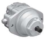
6 FIXED DISPLACEMENT MOTOR Cross section Loop flushing valve Valve plate Piston Roller bearing Output shaft P E Fixed swashplate Cylinder block Name plate Model Code Model-No./Ident-No. Model Code Serial-No A Model Number Serial Number Made in USA P E Place of Manufacture 6 520L0604
7 VARIABLE DISPLACEMENT MOTOR Cross section Valve plate Piston Roller bearing Minimum angle control piston Cradle swashplate Output shaft Cradle swashplate Cylinder block Maximum angle control piston Control valve P E Name plate Model Code Model-No./Ident-No. Model Code Serial-No A Model Number Serial Number Made in USA P E Place of Manufacture 520L0604 7
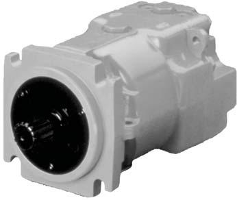
8 FIXED DISPLACEMENT MOTOR, CARTRIDGE MOUNT Cross section Charge relief valve Cylinder block Piston Roller bearing Loop flushing valve Output shaft Valve plate P E Swashplate Name plate Model Code Model-No./Ident-No. Model Code Serial-No A Model Number Serial Number Made in USA P E Place of Manufacture 8 520L0604
9 PICTORIAL CIRCUIT DIAGRAM Control handle Displacement control valve Heat exchanger bypass valve Orificed check valve Reservoir Vacuum gauge Reversible variable displacement pump Servo control cylinder Heat exchanger Charge pressure relief valve Multi-function valve Purge relief valve P Fixed displacement motor Servo pressure relief valves To pump case Charge pump Input shaft Multi-function valve Motor swashplate Output shaft Pump swashplate Servo control cylinder Loop flushing valve Working loop (high pressure) Working loop (low pressure) Suction line Control fluid Case drain fluid SYSTEM SCHEMATIC M3 A A L2 M3 M1 M1 M4 M5 M M2 S L2 B B L1 M2 P E 520L0604 9
10 OVERVIEW Operating Parameters Features and Options 9 Series 90 Model Code Supplement FEATURES AND OPTIONS Motor type Direction of rotation Installation position Other system requirements Parameter 042 MF 055 MF 055 MV 075 MF 100 MF 130 MF SAE C Port connections straight straight straight Standard SPECIFICATIONS Parameter 042 MF 055 MF 055 MV 075 MF 100 MF 130 MF Fixed Fixed Fixed Fixed Fixed Theoretical torque Weight Mass moment of inertia SAE Cartridge L0604
11 OPERATING PARAMETERS Parameter Unit 042 MF 055 MF 055 MV 075 MF 100 MF 130 MF Speed limits min System pressure Continuous Maximum Flow ratings Case pressure Continuous FLUID SPECIFICATIONS Viscosity Minimum Continuous Maximum Temperature Minimum Continuous Maximum Filtration Cleanliness β β β β μ 520L
12 EFFICIENCY GRAPHS Motor performance as a function of operating speed Efficiency vs. speed 100 v = 210 bar (3000 psi) Efficiency (%) t = 210 bar (3000 psi) v = 420 bar (6000 psi) t = 420 bar (6000 psi) Speed (% of rated continuous speed) P E Motor performance as a function of pressure and speed Efficiency plotted at various pressures and speeds % % % psi 3000 bar % Speed % of rated continuous speed P E L0604
13 OVERVIEW Operating parameters SPEED LIMITS Continuous speed Maximum speed Consult Pressure and speed limits SYSTEM PRESSURE W Warning Unintended vehicle or machine movement hazard. System pressure Continuous pressure Maximum pressure CASE PRESSURE C Caution Possible component damage or leakage 520L
14 HYDRAULIC FLUIDS TEMPERATURE AND VISCOSITY Fluid specifications rated temperature maximum temperature minimum temperature recommended operating range minimum viscosity maximum viscosity L0604
15 FLUID AND FILTRATION ¹ β X β β β β β β Design Guidelines for Hydraulic Fluid Cleanliness,, INDEPENDENT BRAKING SYSTEM W Warning Unintended vehicle or machine movement hazard. RESERVOIR Filter β x 520L
16 RESERVOIR (continued) OVERPRESSURE PROTECTION CASE DRAIN L0604
17 SIZING EQUATIONS Selection of drive line components Based on SI units V g η Based on US units V g η V g Δ η m π V g Δ η m π Δ η t Δ η t η V g η V g Variables V g O i Δ O i η η m η t η η m 520L
18 EXTERNAL SHAFT LOADING AND BEARING LIFE are maintained and no external loads are Shaft loading L e T in T out External radial forces on the shaft transfer Allowable shaft loading External shaft load orientation Re = Me /L Shaft loading parameters R e Maximum radial side load Maximum external moment M e L T in T out External shaft load orientation 0 e of shaft 90 e e orientating the external load so that it is rotation e Allowable shaft loading Frame size Parameter Unit M e at 0 M e T in T out L0604
19 TWO-POSITION HYDRAULIC CONTROL (PT) Control schematic diagram L2 M3 A Vg max M1 Legend B L1 X1 P E M2 TWO-POSITION ELECTROHYDRAULIC DISPLACEMENT CONTROL (NA, NB, NC, ND) Control schematic diagram A B L1 L2 M3 Vgmax M1 M2 Legend Coil and connector options Option NB 12V Packard Weather Pack (part no ) Option ND 24V Packard Weather Pack (part no ) Option NA or NC 12 or 24V MS connector (part no ) Mating parts kit Part no. K03383 Ident # (female terminals) Mating parts kit Part no. K03377 Ident # (male terminals) Mating parts kit Part no. MS3101AIOSL-4P (female terminals) P E 520L
20 LOOP FLUSHING W Warning Unintended vehicle or machine movement hazard. under all conditions of Equation Where Flush = Flush Charge Mo Charge Mo or external consumers Recommended charge pump displacement Orifice option Charge pump displacement F0 H0 Schematic diagram of loop flushing valve A Loop flushing flow curves F0 H0 Loop flushing valve cross section L0604
21 SPEED SENSOR digital signal is generated at frequencies Speed Sensor Magnetic ring Specifications Supply voltage* Supply voltage (regulated) Required current Max. current Max. frequency Voltage output (high) Voltage output (low) Temperature range Pulse frequency Speed sensor with Turck Eurofast connector Turck Eurofast Connector 4 pin Mating Connector straight right angle Speed sensor with Packard Weather-Pack connector Red White Black Green Packard Weather-Pack 4 pin Mating Connector A C 520L
22 SHAFT OPTIONS Series 90 shaft options Shaft description Option code Torque rating Frame size availability L0604
23 DISPLACEMENT LIMITERS (055MV ONLY) Motor shaft rotation Shaft direction Flow direction Port A in out out in Displacement limiter adjustment screws W Undesirable vehicle or machine speed hazard. 520L
24 90M42 FIXED MOTOR SAE MOUNT Case drain 0 Vi Port s Port Vi mm L0604
25 90M42 FIXED MOTOR SAE MOUNT (continued) Splined output shaft options Output shaft option Shaft diameter T Full spline length U Major diameter V Length X Pitch diameter W Number of teeth Y Pitch Z Flow direction Shaft rotation Flow direction Port A Port B Out In In Out 99 Vi mm 520L
26 90K55 FIXED MOTOR CARTRIDGE MOUNT Port Vi Port Port Vi ring seal 99 Port Port Axial rted C = T =T =Tn minimum full thread Port Port Vi mm L0604
27 90K55 FIXED MOTOR CARTRIDGE MOUNT (continued) Splined output shaft options Output shaft option Shaft diameter T Full spline length U Major diameter V Pitch diameter W Number of teeth Y Pitch Z Flow direction Shaft rotation Flow direction Port A Port B Out In In Out aces CCW CW case outlet C this surface case outlet Port Vi C ximum x Shaft 9 mm 520L
28 90M55 FIXED MOTOR SAE MOUNT Port Vi Port 99 Port flushing "Y" Vi "X" "Z" 0 0 rts Port Port Vi Axial rted "W" Port e Port Vi mm L0604
29 90M55 FIXED MOTOR SAE MOUNT (continued) Splined output shaft options Output shaft option Shaft diameter T Full spline length U Major diameter V Pitch diameter W Number of teeth Y Pitch Z Flow direction Shaft rotation Flow direction Port A Port B Out In In Out case outlet aces CCW aces CW minimum aces C this surface case outlet Port Port center of Vi aces aces C 0 x P mm 520L
30 90M55 VARIABLE MOTOR CARTRIDGE MOUNT Str Thd O-Ring Boss System Pressure Gage Port M1* Charge Pressure Relief Valve 18.8 [.74] Both Sides Str Thd O-Ring Boss System Pressure Gage Port M2* Max Displacement Limiter Motor Shift Solenoid Valve 75.2 [2.96] Both Sides Str Thd O-Ring Boss Case Outlet Port L1* Motor Shift Hydraulic Control Valve Str Thd O-Ring Boss Charge Pressure Gage Port M3* (On Vertical C L) Port X Str Thd O-Ring Boss [4.63] 6.23 [158.3] "Y" View "Y" (top view) 98.8 [3.89] Max O-Ring Seal [4.66] [4.87] 91.4 [3.60] Split Flange 73.9 [2.91] Case Outlet 86.1 [3.39] Alternate Case Outlet 125 [4.92] Max 109 [4.29] Dia [7.39] Dia Max "X" ± [ ± 0.001] Dia 158 [6.22] "W" 19 [.75] (2) Places 64 [2.52] LEFT SIDE VIEW Min Displacement Limiter Port "B" [1.645] (2) Places Endcap Ports Options 1 = Twin Code 61 8 = Twin Code 62 Twin Ported 1.00 Dia psi (4) Bolt Split Flange Type per SAE J518 (Code 62) Except 20.8 [0.82] Min Full Depth Port "A" Str Thd O-Ring Boss Case Outlet Port L2* [4.95] View "W" (Bottom view) P E mm L0604
31 90M55 VARIABLE MOTOR CARTRIDGE MOUNT (continued) Splined output shaft option Output shaft option Shaft diameter T Full spline length U Major diameter V Pitch diameter W Number of teeth Y Pitch Z Flow direction Shaft rotation Flow direction Port A Port B in out out in 164 [5.75] [10.43] Dia 105 [4.14] [3.95] 35 (4) Places 84.8 [3.34] Dia Min [5.512] [3.908] Coupling must not protrude beyond this surface "U" "W" Pitch Dia 30 Pressure Angle "Y" teeth, "Z" pitch Fillet root side fit per "R" "T" Dia Max [4.409] (2) Places [8.18] Dia R [10] Max "V" Dia [0.875] Dia (2) Places Speed Sensor Connector View "X" (Front View) Splined shaft options (see table) P E mm 520L
32 90V55 VARIABLE MOTOR SAE MOUNT Str Thd O-Ring Boss System Pressure Gage Port M1* Charge Pressure Relief Valve [6.56] Both Sides Str Thd O-Ring Boss Case Outlet Port L1* Str Thd O-Ring Boss System Pressure Gage Port M2* 18.8 [0.74] Both Sides Max Displacement Limiter Motor Shift Hydraulic Control Valve Motor Shift Solenoid Valve Str Thd O-Ring Boss Charge Pressure Gage Port M3* (On Vertical C ) [4.66] 91.4 [3.60] Split Flange [4.87] 72.9 [2.91] Case Outlet Port X Str Thd O-Ring Boss View "Y" (Top View) "Y" 86.1 [3.39] Alternate Case Outlet Min Displacement Limiter Port "B" Endcap Ports Option: 8 = Twin Ported 1.00 DIA psi Split Flange Boss per SAE J518 (Code 62) Except 20.8 [.082] Min Full Thd [1.645] (2) Places Left Side View 209 [8.23] [9.83] [9.82] [9.83] "W" 12.7 [0.50] , [5.000 Dia ] R.5 [0.02] [.56] (4) Places Str Thd O-Ring Boss Servo Pressure Gage Port for Min Displacement 0.64 [0.025] Str Thd O-Ring Boss Case Outlet Port L2* "X" Port "A" View "W" (Bottom View) P E mm L0604
33 90V55 VARIABLE MOTOR SAE MOUNT (continued) Splined output shaft option Output shaft option Shaft diameter T Full spline length U Major diameter V Pitch diameter W Number of teeth Y Pitch Z Flow direction Shaft rotation Flow direction Port A Port B in out out in Str Thd O-Ring Boss per SAE J514 Servo Pressure Gage Port for Max Displacement 146 [5.75] 97 [3.80] 84.8 Min [3.34] Dia Coupling must not protrude beyond this surface 7.9 [.310] "U" "S" "W" Pitch Dia 30 Pressure Angle "Y" Teeth, "Z" Pitch Fillet Root Side Fit per "R" "T" Max Dia "V" Dia 73.2 [2.88] (2) Places [2.254] (4) Places [7.68] Dia R [10] Max (2) Places [14.27].562 Dia (4) Places [2.254] (4) Places 73.2 [2.88] (2) Places Speed Sensor Connector View "X" (front view) Splined shaft options (see table) P E mm 520L
34 90K75 FIXED MOTOR CARTRIDGE MOUNT rted ex minimum full rt case outlet gauge rt Port V rted Port rt Lo e V Mounting flange change relief Ports change relief maximum Port V rted Port rted rted Left rt ex Port maximum shaf rt rt ex Port rt V mm L0604
35 90K75 FIXED MOTOR CARTRIDGE MOUNT (continued) Splined output shaft options Output shaft option Shaft diameter T Full spline length U Major diameter V Pitch diameter W Number of teeth Y Pitch Z Flow direction Shaft rotation Flow direction Port A Port B Out In In Out CCW CW case outlet maximum Co this surface length case outlet maximum Port V tor Port 0 Mounting flange reference Co Shaf mm 520L
36 90M75 FIXED MOTOR SAE MOUNT rt rt t e rt rts Port Port V rted V rted Port Port e rt Por charge relief charge relief rted Lo e rt Lo flushing e rted V "Y" Left oximate maximum 0 rted Port shaf rt Port V rt mm L0604
37 90M75 FIXED MOTOR SAE MOUNT (continued) Splined output shaft options Output shaft option Shaft diameter T Full spline length U Major diameter V Pitch diameter W Number of Teeth Y Pitch Z Flow direction Shaft rotation Flow direction Port A Port B Out In In Out 3.25 [82.6] case outlet case outlet Port CCW CW V tor Port minimum oximate center of gra "U" maximum Co this surface maximum Co 0 Shaf 9 mm 520L
38 90M100 FIXED MOTOR SAE MOUNT [1.645] [1.645] End cap ports 1.00 dia psi (4) bolt split flange type per SAE J518 (code 62) except 20.8 [0.82] minimum full thread depth straight thread O-ring boss per SAE J514 system pressure gauge port M straight thread O-ring boss per SAE J514 case outlet port L [5.04] Loop flushing valve [4.10] [0.510] straight thread O-ring boss per SAE J514 system pressure gauge port M2 1 Port "A" Port "B" [4.08] ports "A" & "B" 92.2 [3.63] Port "A" View "Z" (rear view) axial ported [1.95] [1.95] View "Z" (rear view) twin ported 92.2 [3.63] Port "B" straight thread O-ring boss charge pressure gauge port M [4.31] with charge 93.7 relief [3.69] without charge relief "Z" straight thread O-ring boss per SAE J514 auxiliary systems ports module E only [10.76] Ports "A" & "B" Axial ported Loop flushing valve 6.4 [0.25] Port "B" Twin ported "Y" [10.46] "W" [10.72] View "Y" (top view) [6.06] Approximate center of gravity 14.2 [0.56] (4) places Left side view [9.09] 12.7 [ ] 127 [ R. 0.8 [0.03] maximum ] "X" End cap ports psi (4) bolt split flange type per SAE J518 (Code 62) except 20.8 [0.82] minimum full thread depth [1.645] [1.645] Port "A" straight thread O-ring boss per SAE J514 case outlet port L2 1 View "W" (bottom view) 128 [5.04] P mm L0604
39 90M100 FIXED MOTOR SAE MOUNT (continued) Splined output shaft options Output shaft option shaft diameter T Full spline length U Major diameter V Pitch diameter W Number of teeth Y Pitch Z Length S Flow direction Shaft rotation Flow direction Port A Port B Out In In Out 95 [3.74] case outlet 92.2 [3.63] case outlet (alternative position) [2.254] (2) places Port "B" View "X" (front view) Speed sensor connector Port "A" 73.2 [2.88] (2) places Ø100.6 [Ø3.96] minimum 73.2 [2.88] (2) places [2.254] (2) places R ± 0.76 [0.29 ± 0.03] (4) places Approximate center of gravity 7.87 [0.31] ± 0.64 [2.435 ± 0.025] "T" dia. maximum Coupling must not protrude beyond this surface "S" ± 0.64 [± 0.025] "U" ±0.5 [± 0.02] "F" maximum Ø"V" ± 0.09 [± ] "E" thread R. 2.5 [0.10] maximum Splined shaft options (see chart) Coupling must not protrude beyond 2.33 maximum ± [1.749 ± 0.001] square key x 38.1 long +0.0 [ ] [1.5] Shaft option K3 (keyed) P mm 520L
40 90M130 FIXED MOTOR SAE MOUNT [4.62] with charge relief [4.25] without charge relief [4.40] split flange [4.10] straight thread O-ring boss per SAE J514 charge pressure gauge port M3 1 (to be used as gauge port only) View "Z" (rear view) [4.10] straight thread O-ring boss system pressure gauge port M1 1 Loop flushing valve straight thread O-ring boss system pressure gauge port M [3.80] case drain both sides 51.9 [2.043] (2) places "Z" Port "B" A B View "Y" (top view) "Y" 146 [5.75] both sides "W" Left side view [11.76] 259 [10.20] straight thread O-ring boss case outlet Port L1 1 R. 0.8 [0.03] maximum [ dia.] 12.7 [0.50] 17.4 [0.69] (4) places "X" Port "A" P End cap ports 1.25 dia psi split flange boss 1 per SAE J518 (Code 62) 1/2-13UNC-2B except 23.6 View "W" [0.93] minimum full thread (bottom view) straight thread O-ring boss per SAE J514 case outlet port L2 1 (optional shaft speed sensor location) mm L0604
41 90M130 FIXED MOTOR SAE MOUNT (continued) Splined output shaft options Output shaft option Shaft diameter T Full spline length U Major diameter V Pitch diameter W Number of teeth Y Pitch Z Length S minimum Co ond this surface maximum CCW CW maximum 0 Flow direction Shaft rotation Flow direction Port A Port B Out In In Out mm 520L
42 Notes L0604
43 Notes 520L
44 OUR PRODUCTS Sensors Sauer-Danfoss Mobile Power and Control Systems Market Leaders Worldwide ünster ü 520L0604
Series 90. Axial Piston Motors Technical Information
 Series 90 Axial Piston Motors Technical Information Series 90 Family of Pumps and Motors Series 90 hydrostatic pumps and motors can be applied together or combined with other products in a system to transfer
Series 20 Axial Piston Pumps. Technical Information
 Series 20 Axial Piston Pumps Technical Information General Description INTRODUCTION Sauer-Danfoss a world leader in hydraulic power systems has developed a family of axial piston pumps. DESCRIPTION Sauer-Danfoss
Series 20 Axial Piston Pumps. Technical Information
 Series 20 Axial Piston Pumps Technical Information General Description INTRODUCTION Sauer-Danfoss a world leader in hydraulic power systems has developed a family of axial piston pumps. DESCRIPTION Sauer-Danfoss
Series 40 Axial Piston Motors
 Technical Information powersolutions.danfoss.com Revision history Table of revisions Date Changed Rev February 2017 Corrected document formatting 0703 October 2016 Minor updates 0702 January 2014 Danfoss
Series 20 Axial Piston Motors. Technical Information
 Series 20 xial Piston Motors Technical Information General Description INTRODUCTION Sauer-Danfoss a world leader in hydraulic power systems has developed a family of axial piston motors. DESCRIPTION Sauer-Danfoss
Series 40 Axial Piston Motors. Technical Information
 Series 40 Axial Piston Motors Technical Information Revisions Revisions Table of Revisions Date Page Changed Rev. November 2007 31 correction to maximum torque rating 15 and 19 tooth FB April 2007 29 Revised
Distribuíção, revenda emanutenção. CatálogosOnline. (11) (11)
 (11)") Distribuíção, revenda emanutenção CatálogosOnline (11)4174-3300-(11)4765-6775 www.hmc.com.br MAKING MODERN LIVING POSSIBLE Technical Information Axial Piston Pumps Series 20 powersolutions.danfoss.com
Distribuíção, revenda emanutenção CatálogosOnline (11)4174-3300-(11)4765-6775 www.hmc.com.br MAKING MODERN LIVING POSSIBLE Technical Information Axial Piston Pumps Series 20 powersolutions.danfoss.com
Technical Information Series 45 G Frame powersolutions.danfoss.com
 MAKING MODERN LIVING POSSIBLE Technical Information Series 45 G Frame powersolutions.danfoss.com Contents Frame G Design... 4 Specifications... 5 Performance G74B... 6 Performance G9C... 7 Order code...
Series TMM Axial Piston Motor. Technical Information
 Series TMM Axial Piston Motor Technical Information General Description GENERAL DESCRIPTION These motors are designed primarily to be combined with other products in closed circuit systems to transfer
Series 20 Axial Piston Motors. Technical Information
 Series 20 xial Piston Motors Technical Information General Description INTRODUCTION Sauer-Danfoss a world leader in hydraulic power systems has developed a family of axial piston motors. DESCRIPTION Sauer-Danfoss
Series 90 Axial Piston Pumps. Technical Information
 Series 90 Axial Piston Pumps Technical Information Revisions History of Revisions Table of Revisions Date Page Changed Rev. March 2010 Various Fix O-ring dimensions in dimension drawings FE December 2009
L and K Frame Variable Motors. Technical Information
 L and K Frame Variable Motors Technical Information Revisions Revisions Table of Revisions Date Page Changed Rev. April 2008 6 corrected the schematic drawings BE January 2008 17 removed displacement limiter
Series 45 Axial Piston Open Circuit Pumps Technical Information Frame F
 Design cross section LS contro l (attached to endcap) LS spoo l LS adjustmen t PC spoo l PC adjustmen t Servo piston Bias sprin g Piston Slipper Tapered roller bearing Valve plate Shaft seal Cylinder block
AXIAL PISTON PUMPS AND MOTORS
 HPV-HMF SERIES SECTIONA VIEW AXIA PISTON VARIABE DISPACEMENT PUMP AXIA PISTON FIXED DISPACEMENT MOTOR Purge relief valve High pressure relief valves (adjustable) Cylinder block assembly Shaft seal Output
Technical Information Axial Piston Motors Series 20 powersolutions.danfoss.com
 MKING MODERN LIVING POSSILE Technical Information xial Piston Motors Series 20 powersolutions.danfoss.com General Information Introduction Danfoss a world leader in hydraulic power systems has developed
Series 40 Axial Piston Pumps. Technical Information
 Series 40 Axial Piston Pumps Technical Information Revisions History of Revisions Table of Revisions Date Page Changed Rev. October 2010 last new last page EJ February 2010 last Fix Osaka address EI June
Series 40 Axial Piston Motors Technical Information
 Series 40 Axial Piston Motors Technical Information Series 40 Family of Pumps and Motors Series 40 is a family of hydrostatic pumps and motors for "medium power" applications with maximum loads of 345
H1 Axial Piston Pump Size 147/165, Single. Technical Information
 H1 Axial Piston Pump Size 147/165, Single Technical Information Revisions Revision History Table of revisions Date Page Changed Rev 30 Jul, 2009 First edition AA Jul, 2010 4-6, 10, 12-13 New EC directive
Series 90 Axial Piston Pumps. Technical Information
 Series 90 Axial Piston Pumps Technical Information Using this manual ORGANIZATION AND HEADINGS To help you quickly find information in this manual, the material is divided into sections, topics, subtopics,
T1P Transit Mixer Axial Piston Pump Size 069/089
 Technical Information T1P Transit Mixer Axial Piston Pump Size 069/089 powersolutions.danfoss.com Revision history Table of revisions Date Changed Rev May 2016 Updated to Engineering Tomorrow design. 0201
Series 40 Direct Displacement Pumps
 Technical Information powersolutions.danfoss.com Revision history Table of revisions Date Changed Rev July 2017 Removed outdated images 0703 January 2017 Minor updates 0702 July 2015 Minor edits 0701 February
Series 40 Direct Displacement Pumps. Technical Information
 Series 40 Direct Displacement Pumps Technical Information Revisions History of Revisions Table of Revisions Date Page Changed Rev. September 2013 5, 11 change system pressure specs FB August 2013 all Remove
P90 VARIABLE DISPLACEMENT PUMP T E C H N I C A L C A T A L O G
 P90 VARIABLE DISPLACEMENT PUMP T E C H N I C A L C A T A L O G Variable displacement pump POCLAIN HYDRAULICS Design Slider block Swashplate hold-down Servo piston Servo arm Piston Slipper Displacement
H1 Axial Piston Pump Size 045/053, Single. Technical Information
 H1 Axial Piston Pump Size 045/053, Single Technical Information Revisions Revision History Table of revisions Date Page Changed Rev 30 Jul, 2009 First edition AA Feb 2010 various 14 teeth added BA Jun,
H1 Axial Piston Pump Size 115/130, Single. Technical Information
 H1 Axial Piston Pump Size 115/130, Single Technical Information Revisions Revision History Table of revisions Date Page Changed Rev 30 Jul, 2009 First edition AA Jun, 2010 4-6, 12, 14, New EC directive
Series 45 Open Circuit Axial Piston Pumps. Technical Information. Displacement Piston. Swashplate. Piston. Tapered Roller Bearing
 Series 45 Open Circuit Axial Piston Pumps Technical Information Displacement Piston Piston Swashplate Tapered Roller earing Tapered Roller earing Valve Plate Cylinder lock Kit Shaft Seal General Description
H1 Axial Piston Tandem Pumps Size 045/053
 MAKING MODERN LIVING POSSIBLE Technical Information H1 Axial Piston Tandem Pumps Size 045/053 powersolutions.danfoss.com Revision history Table of revisions Date Changed Rev November 2015 Master Model
Series 90 Axial Piston Pumps. Technical Information
 Series 90 Axial Piston Pumps Technical Information Revisions History of Revisions Table of Revisions Date Page Changed Rev. July 2011 35 Typo, 45cc should be 42cc GB July 2011 all Major update GA August
Technical Information Series 45 H Frame powersolutions.danfoss.com
 MAKING MODERN LIVING POILE Technical Information eries 45 H Frame powersolutions.danfoss.com Contents Frame H Design... 4 pecifications... 5 Performance H57... 6 Performance H75D... 7 Order code... 8 Controls...
H1 Axial Piston Pump Size 147/165, Single
 MAKING MODERN LIVING POSSIBLE Technical Information H1 Axial Piston Pump Size 147/165, Single powersolutions.danfoss.com Revision History Table of Revisions Date Changed Rev Mar 2014 Converted to Danfoss
Series T90 Transit Mixer Drive System
 MAKING MODERN LIVING POSSIBLE Technical Information Series T90 Transit Mixer Drive System powersolutions.danfoss.com Contents Series T90 Transit Mixer Drive Transit Mixer Pump Series T90 General Description...
AXIAL PISTON MOTORS SHMF
 SECTIONAL VIEW Purge relief valve High pressure relief valves (adjustable) Cylinder block assembly Shaft seal Output shaft Valve block Shuttle valve Swashplate 2 SYSTEM CIRCUIT PUMP AND MOTOR CIRCUIT working
Series 42 Axial Piston Pumps. Technical Information
 Series 42 Axial Piston Pumps Technical Information Revisions History of Revisions Table of Revisions Date Page Changed Rev. October 2009 59 Connector/Spool: 6=MS, high gain spool CC October 2009 8, 11
Series 45 Frame J Axial Piston Open Circuit Pumps. Technical Information
 Series 45 Frame J Axial Piston Open Circuit Pumps Technical Information Using this manual ORGANIZATION AND HEADINGS To help you quickly find information in this manual, the material is divided into sections,
Series 45 Axial Piston Open Circuit Pumps Technical Information
 Design Frame E cross section LS control (attached to endcap) LS spool PC spool LS adjustment PC adjustment Adjustable displacement limiter Lifting lug Displacement piston guide Displacement piston Slipper
Series 90 Axial Piston Pumps
 MAKING MODERN LIVING POSSIBLE Series 90 Axial Piston Pumps powersolutions.danfoss.com Revision History Table of Revisions Date Changed Rev March 2014 corrections to pin assignments - page 48 FB February
H1 Axial Piston Single Pumps Size 147/165
 MAKING MODERN LIVING POSSIBLE Technical Information H1 Axial Piston Single Pumps Size 147/165 powersolutions.danfoss.com Revision history Table of revisions Date Changed Rev September 2014 MDC, CCO, and
Series 45 Axial Piston Open Circuit Pumps. Technical Information
 Series 45 Axial Piston Open Circuit Pumps Technical Information Revisions History of Revisions Table of Revisions Date Page Changed Rev. September 28 58-62 dimension changes for Frame J FJ June 28 78,
AXIAL PISTON PUMPS SHPV SECTIONAL VIEW
 AXIAL PISTON PUMPS SHPV SECTIONAL VIEW 2 SYSTEM CIRCUIT PUMP AND MOTOR CIRCUIT working loop (high pressure) working loop (low pressure) control fluid suction line case drain fluid Above figure shows schematically
H1 Axial Piston Tandem Pumps Size 045/053/060/068
 Technical Information H1 Axial Piston Tandem Pumps Size 045/053/060/068 powersolutions.danfoss.com Revision history Table of revisions Date Changed Rev September 2017 add G6 option 0603 June 2017 minor
L and K Frame Variable Motors
 Technical Information powersolutions.danfoss.com Revision history Table of revisions Date Changed Rev April 2018 Model code minimum angle update 0204 November 2016 Minor updates 0203 June 2015 new cartridge
H1T 045/053/060/068 H1 Axial Piston Tandem Pumps
 Technical Information H1T 045/053/060/068 H1 Axial Piston Tandem Pumps www.danfoss.com Revision history Table of revisions Date Changed Rev July 2018 Major revision. 0801 June 2018 Angle sensor chapters
AXIAL PISTON PUMPS SHPV SECTIONAL VIEW
 AXIAL PISTON PUMPS SHPV SECTIONAL VIEW 2 AXIAL PISTON PUMPS SHPV SYSTEM CIRCUIT PUMP AND MOTOR CIRCUIT working loop (high pressure) working loop (low pressure) control fluid suction line case drain fluid
PM50 VARIABLE DISPLACEMENT PUMP CLOSED LOOP CIRCUIT T E C H N I C A L C A T A L O G
 PM50 VARIABLE DISPLACEMENT PUMP CLOSED LOOP CIRCUIT T E C H N I C A L C A T A L O G PM50 - Variable displacement pump POCLAIN HYDRAULICS OVERVIEW PM50 is a variable displacement, axial piston pump, with
Series 42 4T Axial Piston Tandem Pumps
 Technical Information Series 42 4T Axial Piston Tandem Pumps powersolutions.danfoss.com Revision history Table of revisions Date Changed Rev June 2016 converted to new layout 0101 May 2015 Converted to
P90 VARIABLE DISPLACEMENT PUMP T E C H N I C A L C A T A L O G
 P90 VARIABLE DISPLACEMENT PUMP T E C H N I C A L C A T A L O G Variable displacement pump POCLAIN HYDRAULICS Design Piston Slipper Slider block Servo piston Servo arm Displacement control Feedback linkage
H1 Axial Piston Single Pumps Size 147/165
 Technical Information H1 Axial Piston Single Pumps Size 147/165 powersolutions.danfoss.com Revision history Table of revisions Date Changed Rev May 2017 NFPE gen. 3 changes. 0701 November 2015 Master Model
H1 Bent Axis Variable Displacement Motors Frame Size 080 Frame Size 110. Technical Information
 H1 Bent Axis Variable Displacement Motors Frame Size 080 Frame Size 110 Technical Information Revisions History of Revisions Table of revisions Date Page Changed Rev. 1 Dec, 2008 Different pages New frame
DDC20 Axial Piston Variable Displacement Pump
 Technical Information DDC20 Axial Piston Variable Displacement Pump powersolutions.danfoss.com Revision history Table of revisions Date Changed Rev February 2017 Change charge pump housing 0102 January
LPV Axial Piston Closed Circuit Pumps. Technical Information
 LPV Axial Piston Closed Circuit Pumps Technical Information Revisions History of Revisions Table of Revisions Date Page Changed Rev. October 2008 6 added serial number plate drawing AE April 2008 29 changes
Series 42 Closed Circuit Axial Piston Pumps
 Technical Information Series 42 Closed Circuit Axial Piston Pumps www.danfoss.com Revision history Table of revisions Date Changed Rev August 2018 Minor Update 0103 December 2016 Minor Update 0102 June
H1 Axial Piston Single Pumps Size 045/053
 Technical Information H1 Axial Piston Single Pumps Size 045/053 www.danfoss.com Revision history Table of revisions Date Changed Rev May 2018 Major revision. 1101 May 2017 NFPE gen. 3 changes. 1001 November
H1 Axial Piston Single Pumps Size 045/053
 MAKING MODERN LIVING POSSIBLE Technical Information H1 Axial Piston Single Pumps Size 045/053 powersolutions.danfoss.com Revision history Table of revisions Date Changed Rev August 2015 Master model code
Axial Piston Pumps LPV
 Technical Information Axial Piston Pumps LPV powersolutions.danfoss.com Revision history Table of revisions Date Changed Rev September 2017 update model code 0102 July 2015 Danfoss Layout 0100 January
Bent Axis Variable Displ. Motors Series 51 and 51-1
 Technical Information ent xis Variable Displ. Motors Series 51 and 51-1 powersolutions.danfoss.com Revision history Table of revisions Date Changed Rev October 2017 Modified theor. corner power ratings
Axial Piston Pumps Series 40 M46
 Technical Information Axial Piston Pumps Series 40 M46 powersolutions.danfoss.com Revision history Table of revisions Date Changed Rev March 2017 Minor updates - FNR Control options 0209 October 2016 Minor
Group 1 Gear Pumps Technical Information General Information
 General Information OVERVIEW The Sauer-Danfoss Group is a range of peak performance fixed-displacement gear pumps. Constructed of a high-strength extruded aluminum body with aluminum cover and flange,
4T Axial Piston Pumps. Technical Information
 4T Axial Piston Pumps Technical Information Using this manual ORGANIZATION AND HEADINGS To help you quickly find information in this manual, the material is divided into sections, topics, subtopics, and
D Series Gear Motors Including Fan Drive. Technical Information
 D Series Gear Motors Including Fan Drive Technical Information Revisions History of Revisions Table of Revisions Date Page Changed Rev. February 09 - First edition AA 09 Sauer-Danfoss. All rights reserved.
MP1 Axial Piston Pumps Size 28/32, 38/45
 Technical Information MP1 Axial Piston Pumps Size 28/32, 38/45 www.danfoss.com Revision history Table of revisions Date Changed Rev May 2018 add 14 tooth shaft, minor edits 0106 March 2018 update MDC control
H1 Axial Piston Single Pumps Size 147/165
 H1 Axial Piston Single Pumps Size 147/165 www.danfoss.com Revision history Table of revisions Date Changed Rev September 2018 MMC update for M option added. 0802 May 2018 Angle sensor for EDC; FDC note
MOTORS M HYDRAULIC MOTORS
 MOTORS M HYDRAULIC MOTORS T E C H N I C A L C A T A L O G Fixed displaced axial piston motors POCLAIN HYDRAULICS Displacement cm³/rev [in³/rev.] M0 M1 M2 M3 From 7,07 [0.43] to 17,84 [1.09] From 9,08 [0.55]
PMV0 VARIABLE DISPLACEMENT PUMP CLOSED LOOP CIRCUIT T E C H N I C A L C A T A L O G
 PMV0 VARIABLE DISPLACEMENT PUMP CLOSED LOOP CIRCUIT T E C H N I C A L C A T A L O G PMV0 - Variable displacement pump POCLAIN HYDRAULICS OVERVIEW PMV0 is a variable displacement, axial piston pump, with
Medium Duty Piston Pump Variable Displacement Closed Circuit
 Medium Duty Piston Pump Variable Displacement Closed Circuit Model 70160 Model 70360 Model 72400 20.3 cm 3 /r [1.24 in 3 /r] 40.6 cm 3 /r [2.48 in 3 /r] 40.6 cm 3 /r [2.48 in 3 /r] 23.6 cm 3 /r [1.44 in
TPV Variable Displacement Closed Loop System Axial Piston Pump THE PRODUCTION LINE OF HANSA-TMP HT 16 / M / 851 / 0813 / E
 HYDRAULIC COMPONENTS HYDROSTATIC TRANSMISSIONS GEARBOXES - ACCESSORIES THE PRODUCTION LINE OF HANSA-TMP Variable Displacement Closed Loop System CONTENTS General Information... Order Code... Manual Control
Hydraulic Motor/Pump Series F11/F12 zp12
 Hydraulic Motor/Pump zp12 Fixed Displacement zp11 Catalogue HY17-8249/US March 2004 Conversion factors 1 kg... 2.20 lb 1 N... 0.225 lbf 1 Nm... 0.738 lbf ft 1 bar...14.5 psi 1 l...0.264 US gallon 1 cm
Axial Piston Pumps and Motors Service Manual
 Axial Piston Pumps and Motors Service Manual Introduction Introduction Use of this Manual This manual includes information for the normal operation, maintenance, and servicing of the Series 90 family of
Eaton Fixed Displacement HHD Motor and Variable ACA Pump
 Eaton Fixed Displacement HHD Motor and Variable ACA Pump www.hydpump.com Pump Eaton 3923 4623 5423 6423 7620 7640 Motor Eaton 3933 4633 5433 6433 7630 Eaton ACA Pump Technical Data Table of values (theoretical
MP1 Axial Piston Pumps Size 28/32, 38/45
 Technical Information MP1 Axial Piston Pumps Size 28/32, 38/45 powersolutions.danfoss.com Revision history Table of revisions Date Changed Rev August 2016 First Edition 0101 2 Danfoss August 2016 BC00000352en-US
H1 Axial Piston Single Pumps Size 089/100
 MAKING MODERN LIVING POSSIBLE Technical Information H1 Axial Piston Single Pumps Size 089/100 powersolutions.danfoss.com Revision history Table of revisions Date Changed Rev September 2014 MDC, CCO, and
Closed Circuit Axial Piston K and L Frame Variable Motors, SAE Mount
 MAKING MODERN LIVING POSSIBLE Service Manual Closed Circuit Axial Piston K and L Frame Variable Motors, SAE Mount powersolutions.danfoss.com Revision history Table of revisions Date Changed Rev November
D1 High Power Open Circuit Pumps Size 130/145/193/260
 Technical Information D1 High Power Open Circuit Pumps Size 130/145/193/260 Available only for APAC / EU regions powersolutions.danfoss.com Revision history Table of revisions Date Changed Rev January
Transit Mixer Axial Piston Motor Size 070/084/089
 Technical Information Transit Mixer Axial Piston Motor Size 070/084/089 powersolutions.danfoss.com Revision history Table of revisions Date Changed Rev June 2017 Update to Engineering Tomorrow 0202 Mar
H1B 060/080/110/160/210/250 H1 Bent Axis Motors
 H1B 060/080/110/160/210/250 H1 Bent Axis Motors www.danfoss.com Revision history Table of revisions Date Changed Rev August 2018 update adjustment chapter 0504 April 2018 Major layout update, QF080 to
AXIAL PISTON MOTORS MF S E R I E S 2 0 C L O S E D C I R C U I T
 AXIAL PISTON MOTORS MF GENERAL DESCRIPTION Axial piston fixed displacement motors, Series 20, are of swash plate construction with preset displacement, and are intendent for closed circuit operation. The
Axial Piston Pumps Series 40
 Series 40 Family of Pumps and Motors Series 40 is a family of hydrostatic pumps and motors for "medium power" applications with maximum loads of 345 bar (0 psi). These pumps and motors can be applied together
Vickers. Vane Pumps. V Series - Low Noise Vane Pumps High Performance Intravane Pumps For Industrial Applications.
 Vickers Vane Pumps V Series - Low Noise Vane Pumps High Performance Intravane Pumps For Industrial Applications Revised 6/95 560 Introduction Vickers offers the most complete line of hydraulic intravane
Series 40 Pumps Model Code Supplement Variable pumps model code
 odel Code Supplement Single pump model code Product A B C D E F G H J K L 1 2 3 N P 1 2 S T P Product series Code Description P Series 40 variable pump A Displacement 025 24.6 cm³/rev [1.50 in³/rev] 035
H1 Bent Axis Motors Size 060/080/110/160/210/250
 Technical Information H1 Bent Axis Motors Size 060/080/110/160/210/250 powersolutions.danfoss.com Revision history Table of revisions Date Changed Rev March 2018 Model code and ports update. 1108 February
Hydraulic Motor/Pump. Series F11/F12 Fixed Displacement
 Hydraulic Motor/Pump Series F11/F12 Fixed Displacement Series F11/F12 Torque (M) M = D x p x η hm 63 [Nm] Conversion factors 1 kg... 2.20 lb 1 N... 0.225 lbf 1 Nm... 0.738 lbf ft 1 bar...14.5 psi 1 l...0.264
Disc Valve Hydraulic Motors 2000 Series
 Disc Valve Hydraulic Motors 10.2014 inspired hydraulics. Änderungen und Druckfehler vorbehalten 10.2014 EN EATON_Motoren english Highlights Port A Features Three zone design for longer life and true bi-directionality.
RE 91808/ AA4VSE Plug-in dual displacement motor. High pressure range. Series 10 Axial piston swashplate design, SAE model
 AA4VSE Plug-in dual displacement motor Series Axial piston swashplate design, SAE model RE 91808/09.90 RE 91808/09.90 Brueninghaus Hydromatik Size 250 Nominal pressure 350 bar Peak pressure 400 bar High
Closed Circuit Axial Piston Pumps H1 115/130 cc
 MAKING MODERN LIVING POSSIBLE Conversion Manual Closed Circuit Axial Piston Pumps H1 115/130 cc powersolutions.danfoss.com Revision history Table of revisions Date Changed Rev December 2015 First edition
Axial Piston Variable Pump AA4VG
 Electric Drives and Controls Hydraulics Linear Motion and Assembly Technologies Pneumatics Service Axial Piston Variable Pump AA4VG RA 92003-A/06.09 1/64 Replaces: 03.09 Data sheet Series 32 Size 28...
Hydraulic Motor/Pump. Series F11/F12 Fixed Displacement. parker.com/pmde
 Hydraulic Motor/Pump Series F11/F12 Fixed Displacement parker.com/pmde Series F11/F12 Torque (M) M = D x p x η hm 63 [Nm] Conversion factors 1 kg... 2.20 lb 1 N... 0.225 lbf 1 Nm... 0.738 lbf ft 1 bar...14.5
Fixed Displacement Pump A4FO Series 10 Axial Piston Unit, Swashplate Design
 Fixed Displacement Pump A4FO Series 10 Axial Piston Unit, Swashplate Design Sizes 71 0 Nominal pressure 3 bar Peak pressure 400 bar RE 91455/01.94 RE 91455/01.94 Replaces 07.88 Other fixed displacement
Heavy Duty Hydrostatic Transmissions
 Heavy Duty Hydrostatic Transmissions Features and Benefits Typical Applications Construction Transit Mixer Road Roller Paver Motor Grader Loader Dozer Material Handling & Utility Crane Sweeper Lift Truck
Series 2 Variable Displacement Piston Pump
 Series 2 Variable Displacement Piston Pump ACL 64-105cm 3 /r (3.9-6.4in 3 /r) 2 eaton Series 2 Variable Displacement Piston Pump E-PUPI-MC004-E1 January 2010 Series 2 Variable Displacement Piston Pump
GEAR MOTORS D Series Gear Motors including Fan Drive l Technical Information
 GEAR MOTORS D Series Gear Motors including Fan Drive l Technical Information 2 D SERIES GEAR MOTORS I TECHNICAL INFORMATION History of revisions Date Page Changed Rev. Feb. 2009 - First edition AA Nov.
Vane Pumps. VMQ Series Vane Pumps For Industrial and Mobile Applications Displacements to 215 cm 3/ r (13.12 in 3 /r) Pressures to 260 bar (3800 psi)
 Pressures to 260 bar (3800 psi)") Vickers Vane Pumps VMQ Series Vane Pumps For Industrial and Mobile Applications Displacements to 215 cm 3/ r (13.12 in 3 /r) Pressures to 260 bar (3800 psi) 5008.00/EN/0596/A A.25 Introduction From the
Vickers Vane Pumps VMQ Series Vane Pumps For Industrial and Mobile Applications Displacements to 215 cm 3/ r (13.12 in 3 /r) Pressures to 260 bar (3800 psi) 5008.00/EN/0596/A A.25 Introduction From the
Hydraulic Motor/Pump. Series F11/F12 Fixed Displacement. parker.com/pmde
 Hydraulic Motor/Pump Series F11/F12 Fixed Displacement parker.com/pmde Series F11/F12 Torque (M) M = D x p x η hm 63 [Nm] Conversion factors 1 kg... 2.20 lb 1 N... 0.225 lbf 1 Nm... 0.738 lbf ft 1 bar...14.5
Fixed Displacement Motor A10FM A10FE
 Electric Drives and Controls Hydraulics inear Motion and ssembly Technologies Pneumatics Service Fixed Displacement Motor 10FM 10FE RE 91 172/06.06 1/24 Replaces: 01.03 Technical Data Sheet Size 10...63
PM45 VARIABLE DISPLACEMENT PUMP CLOSED LOOP CIRCUIT T E C H N I C A L C A T A L O G
 PM45 VRILE DISPLCEMENT PUMP CLOSED LOOP CIRCUIT T E C H N I C L C T L O G PM45 - Variable displacement pump POCLIN HYDRULICS OVERVIEW PM45 is a variable displacement, axial piston pump, with swashplate
Vickers. Vane Pumps. Double Thru-drive Vane Pumps. High speed, high pressure VQT Series for mobile equipment. Released 7/93
 Vickers Vane Pumps Double Thru-drive Vane Pumps High speed, high pressure VQT Series for mobile equipment Released 7/93 612 Introduction Double VQT high performance pumps are fixed displacement units that
Axial piston variable pump A4VG Series 32. Europe. RE-E Edition: Replaces:
 Axial piston variable pump A4VG Series 32 Europe RE-E 92003 Edition: 04.2016 Replaces: 06.2012 High-pressure pump for applications in a closed circuit Size 28 to 125 Nominal pressure 400 bar Maximum pressure
Variable Displacement Pump A4VG for closed circuits
 RE 92 003/05.99 RE 92 003/05.99 replaces: 02.98 Variable Displacement Pump A4VG for closed circuits Sizes 28...250 Series 3 Nominal pressure 400 bar Peak pressure 450 bar A4VG...EP Index Features 1 Ordering
Hydraulic Motor/Pump. Series F11/F12 Fixed Displacement. parker.com/pmde
 Hydraulic Motor/Pump Series F11/F12 Fixed Displacement parker.com/pmde Series F11/F12 Torque (M) M = D x p x η hm 63 [Nm] Conversion factors 1 kg... 2.20 lb 1 N... 0.225 lbf 1 Nm... 0.738 lbf ft 1 bar...14.5
TPV Variable Displacement Closed Loop System Axial Piston Pump THE PRODUCTION LINE OF HANSA-TMP HT 16 / M / 852 / 0815 / E
 HYDRAULIC COMPONENTS HYDROSTATIC TRANSMISSIONS GEARBOXES - ACCESSORIES Certified Company ISO 9001-14001 ISO 9001 Via M. L. King, 6-41122 MODENA (ITALY) Tel: +39 059 415 711 Fax: +39 059 415 729 / 059 415
ENGINEERING DATA. High Torque, Low Speed Motors H, S, 2000, 6000, and 10,000 Series. w w w. F l u i D y n e F P. c o m
 ENGINEERING DATA High Torque, Low Speed Motors H, S, 2000, 6000, and 10,000 Series Interchangeable with: Charlynn White Ross Parker Danfoss w w w. INDEX Cross Reference Guide...2 Introduction...3 H-Series...4
Disc Valve Hydraulic Motors 4000 Compact Series
 Disc Valve Hydraulic Motors 10.2014 inspired hydraulics. Änderungen und Druckfehler vorbehalten 10.2014 EN EATON_Motoren english Port B Port A Features Shuttle Valve with Back- Pressure Relief Valve Highlights