Series 90. Axial Piston Motors Technical Information
|
|
|
- Berenice Hall
- 5 years ago
- Views:
Transcription


1 Series 90 Axial Piston Motors Technical Information
2 Series 90 Family of Pumps and Motors Series 90 hydrostatic pumps and motors can be applied together or combined with other products in a system to transfer and control hydraulic power. They are intended for closed circuit applications. Series 90 variable displacement pumps are compact, high power density units. All models utilize the parallel axial piston / slipper concept in conjunction with a tiltable swashplate to vary the pump s displacement. Reversing the angle of the swashplate reverses the flow of oil from the pump and thus reverses the direction of rotation of the motor output. Series 90 pumps include an integral charge pump to provide system replenishing and cooling oil flow, as well as control fluid flow. Series 90 pumps also feature a range of auxiliary mounting pads to accept auxiliary hydraulic pumps for use in complementary hydraulic systems. A complete family of control options is available to suit a variety of control systems (mechanical, hydraulic, electric). Series 90 motors also use the parallel axial piston / slipper design in conjunction with a fixed or tiltable swashplate. They can intake/discharge fluid through either port; they are bidirectional. They include an optional loop flushing feature that provides for additional cooling and cleaning of fluid in the working loop. In the variable motors, hydraulic or solenoid-operated two-position control valves move the swashplate between minimum and maximum displacement positions. Series 90 Advanced Technology Today 7 Sizes of Variable Displacement Pumps 5 Sizes of Fixed Displacement Motors 2 Sizes of Variable Displacement Motors SAE and Cartridge Mount Configurations Electric and Hydraulic Controls for Variable Motors Efficient Axial Piston Design Complete Family of Control Systems Proven Reliability and Performance Compact, Lightweight Worldwide Sales and Service Copyright 1988, 1989, 1990, 1991, 1994, 1997, Sauer-Sundstrand Company. All rights reserved. Contents subject to change. All trademarks property of their respective owners. Printed in U.S.A. 1198H 2
3 Contents Series 90 Family of Pumps and Motors... 2 Sectional Views... 4 System Circuit Description... 5 Motor Circuit Description... 5 Technical Specifications... 6 Model Code... 8 Hydraulic Equations Helpful for Motor Selection... 9 System Parameters Case Pressure Speed Limits Pressure Limits...11 Fluid Specifications Hydraulic Fluid Temperature and Viscosity Fluid And Filtration System Requirements Brake Warning Reservoir Overpressure Protection Case Drain Charge Flow Requirements Product Features and Options Loop Flushing Displacement Limiters Speed Sensor Options Two-Position Hydraulic Control PT Two-Position Electrohydraulic Displacement Control NA, NB, NC, ND Loading, Life, and Efficiency External Loading and Bearing Life Efficiency Graphs Series MF SAE Flange Dimensions Series MF Cartridge Dimensions Series MF Cartridge Dimensions Series MF SAE Flange Dimensions Series MV Cartridge Dimensions Series MV SAE Flange Dimensions Series MF Cartridge Dimensions Series MF SAE Flange Dimensions Series MV Cartridge Dimensions Series MV SAE Flange Dimensions Series MF SAE Flange Dimensions Series MF SAE Flange Dimensions
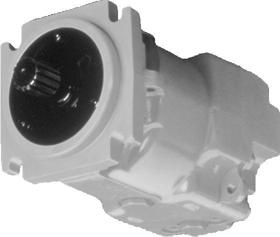
4 Sectional Views Valve Plate Piston Roller Bearing Output Loop Flushing Valve Fixed Swashplate Cylinder Block Series 90 Fixed Displacement Motor Cross Section P E Valve Plate Piston Roller Bearing Minimum Angle Control Piston Cradle Swashplate Output Cylinder Block Electric 2-Position Control (Option) (4-Way, 2 Position Valve) Cradle Swashplate Series 90 Variable Displacement Motor Cross Section (Partial Section with Cradle Swashplate in Full Displacement Position) Maximum Angle Control Piston P E 4
5 System Circuit Description A hydrostatic transmission is shown made up of a Series 90 Fixed Motor (right) and a Series 90 Variable Pump. The shaded half of the circuit includes Control Handle Reversible Variable Displacement Pump Displacement Control Valve Orificed Check Valve Servo Control Cylinder Heat Exchanger Bypass Valve Heat exchanger Multi-Function Valve servo pressure relief valve Pump Charge Relief Valve to pump case motor features. A suction filtration configuration is shown. Pressure limiters are included on the pump. Note the position of the reservoir and heat exchanger. Reservoir Vacuum Gauge Loop Flushing Relief Valve Charge Pressure Case Flow High Pressure Control Pressure Suction Flow Fixed Displacement Motor Input Pump Swashplate Servo Control Cylinder Charge Pump Multi-Function Valve Loop Flushing Valve Motor Swashplate Output Pump Motor P E Motor Circuit Description Circuit schematics are shown for the fixed and variable motors. The system ports "A" and "B" hook up to the high pressure work lines. The motor receives high pressure fluid at its inlet port and discharges lower pressure fluid through the outlet port. Either port can act as inlet or outlet; flow can be bidirectional. System port pressure can be gauged through ports M1 and M2. The motor has two case drains (L1 and L2). The higher case drain should be used to ensure complete filling of the case. The motor may or may not include loop flushing. Loop flushing provides additional cooling and filtration to the working group. The variable motor circuit includes a two-position hydraulic or electrohydraulic control. A L2 M3 Vg max M1 Ports: A, B = Main pressure lines L1, L2 = Case drain lines M1, M2 = Gauge ports for ports "A" and "B" M3 = Gauge port for charge pressure X1 = Motor shift pressure A L2 M3 M1 X1 B L1 M2 Hydraulic Electrohydraulic P E Variable Motor Circuit Schematic B L1 M2 Fixed Motor Circuit Schematic P
6 Technical Specifications Specifications for Series 90 motors are listed on these two pages. For definitions of the various specifications, see the related section in this publication. Not all hardware options are available for all configurations; consult the Series 90 Motor Model Code Supplement or Price Book for more information. General Specifications Product Line Motor Type Direction of Rotation Installation Position Other System Requirements Series 90 Motors In-line, axial piston, closed loop, positive displacement motors. Bidirectional, see outline drawings for rotation vs flow direction information Discretionary, but the housing must be filled with hydraulic fluid. Independent braking system, overpressure protection, suitable reservoir, proper filtration Hardware Specifications Model Swashplate 042 MF 055 MF 075 MF 100 MF 130 MF 055 MV 075 MV Fixed Fixed Fixed Fixed Fixed Variable T E Variable Displacement cm 3 3 / rev (in /rev) M aximum 42 (2.56) 55 (3.35) 75 (4.57) 100 (6.10) 130 (7.93) 55 (3.35) 75 (4.57) Minimum (1.16) 26 (1.59) Weight kg S AE 15 (34) 22 (49) 26 (57) 34 (74) 45 (99) 39 (86) 44 (98) (lb) C artridge* 21 (46) 26 (57) 33 (72) (88) 46 (101) Moment of Inertia k g m ( lb ft ) 3.9 (92.6) 6.0 (142) 9.6 (228) 15.0 (356) 23.0 (546) 6.0 (142) 9.6 (228) Hardware Options T E Model 042 MF 055 MF 075 MF 100 MF 130 MF 055 MV 075 MV Types of Mounting SAE B, SAE C, SAE C, SAE C, SAE C, (SAE flange size SAE C SAE D Cartridge* Cartridge* Cartridge* Cartridge* Cartridge* per SAE J744) Port Connections Twin Twin, Twin, Twin, Twin, Axial Axial Axial Axial Twin Twin Output Options Spline Spline, Tapered, Straight Spline, Tapered, Straight Spline, Tapered, Straight Spline Spline Spline Two-Position Electrohydraulic Control Options Control, Two-Position Hydraulic Control Loop Flushing l l l l l l l Charge Relief Valve l l l l l l l Displacement Limiters l l Speed Sensor - m m m m m m T E l standard m optional - not available / not applicable * Cartridge design motors are compatible with Fairfield CT and CW planetary wheel drives. See dimensional drawings for flange dimensions. 6
7 System Parameters Model Speed Limits Fluid Specifications rev/min *Temperature measured at hottest point in the system, usually the motor case drain line. **Special hardware is required. Contact Sauer-Sundstrand representative. 042 MF 055 MF 075 MF 100 MF 130 MF 055 MV 075 MV Rated at max disp Maximum at max disp Max. Attainable** Rated at min disp Maximum at min disp S ystem Pressure bar (psi) R ated 420 (6000) M aximum 480 (7000) F low at Rated Speed l /min (gpm) 193 (51) 234(62) 296 (78) 365 (96) 442 (117) 234 (62) 296 (78) M ax Corner Power k W (hp) 155 (208) 187 (251) 237 (318) 292 (392) 354 (475) 187 (251) 237 (318) C ase Pressure bar (psi) C ontinuous 3 (44) M aximum ( cold start) 5 (72) Hydraulic Fluid Viscosity mm 2 /s or cst (SUS) Ratings and data are based on operation with premium petroleum-based, anti-wear, hydraulic fluids containing oxidation, rust, and foam inhibitors. See SAS publications BLN-9887 or for more information. See page 11. Rec. Range (66-278) M inimum ( intermitant) 7 (49) M aximum ( cold start) 1600 (7500) T emperature* C ( F) M inimum ( cold start) - 40 (-40) Continuous 104 (220) Maximum 115 (240) Fluid Cleanliness Level ISO 4406 Class 18/13 Recommended Filtration Efficiency Suction Filtration β = 75 (β ) Charge Filtration β = 75 ( β ) T E T E 7
8 Model Code The model code is a modular description of a specific product and its options. To create a model code to include the specific options desired, see the Series 90 Model Code Supplement or the Series 90 Price Book. Name Plate Name Plate Model Number Serial Number saue Ames, Iowa, U.S.A. Model Code 90M055 NC 0 N 8 N 0 C6 C W 00 NNN Model No. Neumünster, Germany Typ Ident Nr N Serial No. Fabr Nr MADE IN GERMANY Model Code Ident. Number Model Number Serial Number saue Ames, Iowa, U.S.A. Model Code 90V055 NB N 4 S1 W 00 NNN Model No. Neumünster, Germany Typ Ident Nr A Serial No. Fabr Nr MADE IN U.S.A. Model Code Ident. Number 9 0 Place of Manufacture Place of Manufacture M N C 0 N 7 N 0 C 6 W 0 0 N N N Series Charge Pressure Setting Type Not Applicable Size (cc) Fixed - Not Applicable Variable - Servo Orifices Fixed - Not Applicable Variable - Control Type Special Hardware Fixed - Not Applicable Variable - Unit Type Fixed - Not Applicable Variable - Control Supply Orifice Not Applicable Charging System End Cap Ports Output Fixed - Not Applicable Variable - Maximum Displacement Setting Fixed - Not Applicable Variable - Minimum Displacement Setting P E 8
9 Hydraulic Equations Helpful for Motor Selection The following equations are helpful when sizing hydraulic motors. Generally, the sizing process is initiated by an evaluation of the machine system to determine the required motor speed and torque to perform the necessary work function. Refer to Metric System: Vg n Input flow Q e = l/min 1000 η v BLN-9885, "Selection of Driveline Components," for a more complete description of hydrostatic driveline sizing. First, the motor is sized to transmit the maximum required torque. The pump is then selected as a flow source to achieve the maximum motor speed. Inch System: MD MS Input flow Q e = gpm 231 EV Vg p η m Output torque M e = Nm 20 π Output torque MT = MD p ET 2 π lbf in Vg n p η m Output power P e = kw MD MS p ET Output power P = hp Q e 1000 η v Motor Speed n = min -1 (rpm) Vg Motor Speed MS = Q e 231 EV MD min -1 (rpm) Vg = Motor displacement per rev. cm 3 n = Hydrostatic motor speed min -1 (rpm) p = Differential hydraulic pressure bar MD = Motor displacement per rev. in 3 MS = Hydrostatic motor speed min -1 (rpm) p = Differential hydraulic pressure psi η v = Motor volumetric efficiency η m = Motor mechanical efficiency EV = ET = Motor volumetric efficiency Motor mechanical efficiency 9
10 System Parameters Case Pressure Under normal operating conditions, case pressure must not exceed the continuous case pressure rating. Momentary case pressures exceeding this rating are acceptable under cold start conditions, but still must stay below the maximum case pressure rating. Operation with case pressure in excess of Speed Limits Rated Speed is the speed limit recommended at full power condition, and is the highest value at which normal life can be expected. In a machine propel application, maximum motor speed during unloaded, on-road travelling on level ground should not exceed this limit. Maximum Speed is the highest operating speed permitted and cannot be exceeded without reducing product life and risking immediate failure and loss of hydrostatic power (which may create a safety hazard). In a machine propel application, maximum motor speed must never exceed this limit during any these limits may result in external leakage due to damage to seals, gaskets, and/or housings. Case Pressure bar psi Continuous 3 44 Maximum (cold start) 5 72 T E condition (i.e., top speed downhill). In addition, applications must have a braking system, redundant to the hydrostatic transmission, which will stop and hold the vehicle should hydrostatic control be lost. Maximum with Special Hardware requires approval from Sauer-Sundstrand Application Engineering. Special unit hardware and/or special operating conditions may be required. Consult Bulletin BLN-9884 ( Pressure and Speed Limits ) when determining speed limits for a particular application. Speed Limits rev/min 042 MF 055 MF 075 MF 100 MF 130 MF 055 MV 075 MV Rated at max disp Maximum at max disp Max w/ Spec Hardware Rated at min disp Maximum at min disp T E 10
11 Pressure Limits System pressure is the differential pressure between system ports A and B. It is a dominant operating variable affecting hydraulic unit life. High pressure, which results from high load, reduces expected life in a manner similar to many mechanical assemblies such as engines and gear boxes. There are load-to-life relationships for the rotating group and life predictions can be performed by Sauer- Sundstrand Application Engineering. Rated system pressure is the highest normally occurring system pressure which should be encountered during normal machine use. Motors should be sized so that the peak machine load can be developed at or below this pressure. In most applications, the pump pressure limiter setting should not exceed this value. Adequate hydrostatic system life will not be achieved if the system is runs at or near this pressure continuously. Maximum system pressure is the highest intermittent pressure allowed. It is determined by the maximum machine load demand, usually during acceleration or load spikes. Maximum pressure is assumed to occur usually less than 2% of the total operating time. Both the maximum and rated pressure limits must be satisfied to achieve the expected life. Continuous pressure is the pressure at which the hydrostatic system could operate continuously and still achieve acceptable hydrostatic life. This pressure level varies depending on operating speed, and on the life requirements for a particular application. While most mobile applications require system pressure to vary widely during operation, a "weighted average" pressure can be derived from a machine duty cycle. (A duty cycle is a means of quantifying the pressure and speed demands of a particular system on a percent time basis.) Once a duty cycle has been determined or estimated for a specific application, contact Sauer-Sundstrand Application Engineering for system life ratings for the application. All pressure limits are differential pressures (referenced to charge pressure) and assume normal charge pressure and no externally applied shaft loads. Pressure Limits bar psi Maximum Rated T E 11
12 Fluid Specifications Hydraulic Fluid Ratings and data for Series 90 products are based on operating with premium hydraulic fluids containing oxidation, rust and foam inhibitors. These fluids must possess good thermal and hydrolytic stability to prevent wear, erosion and corrosion of the internal components. These include premium turbine oils, API CD engine oils per SAE J183, M2C33F or G automatic transmission fluids, Dexron II or IIE (not Dexron III) meeting Allison C3 or Caterpillar TO-2 and certain agricultural tractor fluids. Hydraulic fluids per DIN 51524, part 2 (HLP) and part 3 (HVLP) are suitable. Fire resistant fluids are also suitable at modified operating conditions. For more information see Sauer-Sundstrand publication BLN-9887 or Refer to publication ATI-E 9101 for information relating to biodegradable fluids. It is not permissible to mix hydraulic fluids. Contact your Sauer-Sundstrand representative for more information. Temperature and Viscosity Temperature and viscosity requirements must be concurrently satisfied. The data shown at right assumes petroleum/mineral based fluids. The high temperature limits apply at the hottest point in the transmission, which is normally the motor case drain. The motor should generally be run at or below the continuous temperature. The maximum temperature is based on material properties and should never be exceeded. Cold oil will generally not affect durability of the transmission components, but it may affect the ability to flow oil and transmit power; therefore temperatures should remain 16 C (30 F) above the pour point of the hydraulic fluid. The minimum temperature relates to the physical properties of component materials. For maximum unit efficiency and bearing life the fluid viscosity should remain in the recommended viscosity range. The minimum viscosity should be encountered only during brief occasions of maximum ambient temperature and severe duty cycle operation. The maximum viscosity should be encountered only at cold start. Heat exchangers should be sized to keep the fluid within these limits. Testing to verify that these temperature limits are not exceeded is recommended. Viscosity mm 2 / s (cst) SUS Recommended Range Minimum (intermittent) 7 49 Maximum (cold start) T E Temperature C F Minimum Continuous Maximum T E 12
13 Fluid And Filtration To prevent premature wear, it is imperative that only clean fluid enter the hydrostatic transmission circuit. A filtration system capable of controlling the fluid cleanliness to ISO 4406 Class 18/13 (SAE J1165) or better, under normal operating conditions, is recommended. The selection of a filter depends on a number of factors including the contaminant ingression rate, the generation of contaminants in the system, the required fluid cleanliness, and the desired maintenance interval. Filters are selected to meet the above requirements using rating parameters of efficiency and capacity. Filter efficiency may be measured with a Beta ratio 1 (β x ). For simple closed circuit transmissions with controlled reservoir ingression, a filter with a (β 10 ) ratio of 1.5 to 2 has been found to be satisfactory. For some open circuit systems, and closed circuits with cylinders being supplied from the same reservoir, a considerably higher filter efficiency is recommended. This also applies to systems with gears or clutches using a common reservoir. For these systems, (β x ) ratios of 10 to 20 are typically required. Since each system is unique, the filtration requirement for that system will be unique and must be determined by test in each case. It is essential that monitoring of prototypes and evaluation of components and performance throughout the test program be the final criteria for judging the adequacy of the filtration system. See publication BLN-9887 or for more information. Fluid Cleanliness Level ISO 4406 Class 18/13 Recommended Filtration Efficiency Suction Filtration β = 75 (β ) Charge Filtration β = 75 ( β ) T E 1 Filter β x -ratio is a measure of filter efficiency defined by ISO It is defined as the ratio of the number of particles greater than a given diameter ("x" in microns) upstream of the filter to the number of these particles downstream of the filter. 13
14 System Requirements Brake Warning The loss of hydrostatic drive line power in any mode of operation (e.g., forward, reverse, or "neutral" mode) may cause the loss of hydrostatic braking capacity. A braking system, redundant to the hydrostatic transmission and adequate to stop and hold the machine, must therefore be provided in case the condition should develop. Reservoir The reservoir should be designed to accommodate maximum volume changes during all system operating modes and to promote de-aeration of the fluid as it passes through the tank. A suggested minimum total reservoir volume is 5/8 of the maximum charge pump flow per minute with a minimum fluid volume equal to 1/2 of the maximum charge pump flow per minute. This allows 30 seconds fluid dwell for removing entrained air at the maximum return flow. This is usually adequate to allow for a closed reservoir (no breather) in most applications. Overpressure Protection Series 90 motors (as well as other system components) have pressure limitations. As Series 90 motors are not equipped with overpressure protection, it is necessary that relief valves or pressure limiters are present elsewhere in the high pressure circuit to protect components from excessive pressures. Series 90 pumps are designed with a sequenced pressure limiting system and high pressure relief valves. When the preset pressure is reached, the pressure limiter system acts to rapidly de-stroke the pump in order to limit the system pressure. For unusually rapid load application, the high pressure relief valve function is available to also limit the pressure level. Refer to publication BLN for more information. The reservoir outlet to the charge pump inlet should be above the bottom of the reservoir to take advantage of gravity separation and prevent large foreign particles from entering the charge inlet line. A 125 µm screen over the outlet port is recommended. The reservoir inlet (fluid return) should be positioned so that flow to the reservoir is discharged below the normal fluid level, and also directed into the interior of the reservoir for maximum dwell and efficient deaeration. A baffle (or baffles) between the reservoir inlet and outlet ports will promote de-aeration and reduce surging of the fluid. NOTE: For systems with relief valves only, high pressure relief valves are intended for transient overpressure protection and are not intended for continuous pressure control. Operation over relief valves for extended periods of time may result in severe heat build up. High flows over relief valves may result in pressure levels exceeding the nominal valve setting and potential damage to system components. Case Drain A case drain line must be connected to one of the case outlets (L1 or L2) to return internal motor leakage and loop flushing flow to the system reservoir. The higher of the two case outlets should be used to promote complete filling of the motor case. Since the motor case drain fluid is typically the hottest fluid in the system, it is advantageous to return this flow through the heat exchanger. 14
15 Charge Flow Requirements (A) Charge Flow Requirement - Pump Refer to the product information for the specific pump being used in the circuit to determine the charge flow requirement, QP. (B) Charge Flow Requirement - Motor Determine the motor speeds and the maximum system pressure. Referring to the accompanying figure, "Charge Flow Requirement - Series 90 Motor," determine the flow factor of the motor, FM Using the following equation, determine charge flow requirement for the Motor: QM = QM = FM x Frame Size 75 FM x Frame Size = Charge Flow Req d - Motor (gpm) = Charge Flow Req d -Motor (lpm) Flow Factor Fm min-1 (rpm) 3600 min-1 (rpm) 3000 min-1 (rpm) 2000 min -1 (rpm) 1000 min-1 (rpm) p psi p bar System Pressure P E (C) Total Charge Flow Requirements The total charge flow requirement (QT) is the sum of the flow requirements of each of the components in the system; namely: QT = QP + QM 1 + QM Q Auxiliary = Total Charge Flow Req'd 15
16 Product Features and Options Loop Flushing Series 90 motors may incorporate an integral loop flushing valve. Installations that require additional fluid to be removed from the main hydraulic circuit because of fluid cooling requirements, or circuits requiring the removal of excessive contamination, will benefit from loop flushing. A loop flushing valve will remove heat and contaminants from the main loop at a rate faster than otherwise possible. In series 90 motors, the current loop flushing relief valve design includes an orifice which controls flushing flow under most conditions. A combination of orifice size and charge pressure relief setting will produce a specific flushing flow. A number of orifice sizes are available, resulting in several different flushing flow rates as illustrated in the accompanying graph. Loop flushing flow between gpm (5 and 15 l/min) is generally suitable for most applications, but specific operating conditions may require more flow. The specific rate of flushing flow selected for an application will depend on the amount of fluid volume in the working loop, the number of motors in the circuit, and possibly other factors. Motor loop flushing flow must be considered in the calculation of total pump charge flow required, to ensure that charge pressure is not reduced excessively in any operating condition. See section titled "Charge Flow Requirements." WARNING Excessive motor loop flushing flow may result in the inability to build required system pressure in some conditions. Correct charge pressure must be maintained under all conditions of operation to maintain pump control performance in hydrostatic systems. NOTE: Consult your Sauer-Sundstrand representative if loop flushing will be required in a circuit which contains a flow divider / combiner. A remote loop flushing valve may be required. Loop Flushing Shuttle Valve Charge Relief Valve Flushing Flow (US gal/min) (bar) Low Loop Pressure (psi ) (l/min) Loop Flushing Valve P E Loop Flushing Flow Rates T E 175 F (80 C) 10.5 cst Fluid 16
17 Displacement Limiters Series 90 variable motors include mechanical displacement (stroke) limiters. Both maximum and minimum displacement of the motor can be limited. Motor Rotation Flow Direction P ort "A" Port "B" Adjustments can be made by loosening the seal lock nut and rotating the limiter screw. The seal lock nut must be re-torqued after any adjustment. Clockwise (CW) Counterclockwise (CCW) OUT IN IN OUT Series 90 variable motors are shipped with the minimum displacement limiter set at the lowest displacement setting and the maximum displacement setting set at full displacement. WARNING Care should be taken in adjusting displacement limiters to avoid an undesirable condition of output flow or speed. The sealing lock nut must be re-torqued after every adjustment to prevent an unexpected change in output conditions and to prevent external leakage Tamper-Resistant Cap Seal Lock Nut Maximum Displacement Limiter Screw T E Minimum Displacement Limiter Screw Seal Lock Nut Tamper-Resistant Cap Displacement Limiters SAE Flange Version shown (Cartridge Version similar) E E 17
18 Speed Sensor Series 90 motors are available with an optional speed sensor for direct measurement of motor output speed. This sensor may also be used to sense the direction of motor rotation. A special magnetic speed ring is pressed onto the outside diameter of the cylinder block and a Hall effect pulse pickup sensor is located in the motor housing. The sensor accepts supply voltage and outputs a digital pulse signal in response to the speed of the ring. The output changes its high/low state as the north and south poles of the permanently magnetized speed ring pass by the face of the sensor. The digital signal is generated at frequencies suitable for microprocessor based controls. This sensor will operate with a supply voltage of 4.5 to 15 VDC, and requires a current of 12 ma at 5.0 VDC under no load. Maximum operating current is 20 ma at 5VDC. Maximum operating frequency is 15 khz. Output voltage in High State (VOH) is sensor supply voltage minus 0.5 VDC, minimum. Output voltage in Low State (VOL) is 0.5 VDC, maximum. NOTE: It is not acceptable to energize the VDC ppu with 12VDC battery voltage; it must be energized by a regulated power supply. If it is desirable to energize the sensor with battery voltage, contact Sauer-Sundstrand for an optional speed sensor. Refer to PIB 9602M. The sensor is available with a Packard Weather- Pack 4-pin sealed connector or Turck Eurofast M12x1 4-pin connector. NOTE: Strain relieve and / or protective cover installation with this device is required by the customer. NOTE: System FMEA must be done by the customer for each application with the help of Sauer- Sundstrand Application Engineering. Supply Voltage Required Current Max Max VOH VOL Current Frequency Pulse/Rev Connector (standard) Speed Sensor Magnetic Ring Cylinder Block Speed Sensor Specs Red White Black Green 42cc VDC 12mA at 5 VDC (no load) 20 ma at 5VDC & 1kH 15kHz Supply VDC VDC 55cc VDC Max 75cc cc 63 Packard Weather-Pack 4-pin SAUER-SUNDSTRAND Mating Parts Kit Part No. K03379 (4 pin) Packard Weather-Pack 4 Socket Tower Connector A B C D 130cc 69 Supply Voltage + Speed Signal Gnd Common Direction SAUER-SUNDSTRAND Mating Parts Kit Part No. K14956 or Ident. No (straight) Part No. K14957 or Ident. No (right angle) Turck Eurofast 4 Pin Connector Key (Ref) Pin 2 Direction Pin 1 Supply Voltage + "Y" Pin 3 Speed Signal Speed sensor T E Pin 4 Gnd Common 12,7 [0.50] Wrench Flats View "Y" P E P E Cross-Section of Speed Sensor on Cylinder Kit 18
19 Options Series 90 motors are available with a variety of splined, straight keyed, and tapered shaft ends. Nominal shaft sizes and torque ratings are shown in the accompanying table. Torque ratings assume no external radial loading. Continuous torque ratings for splined shafts are based on spline tooth wear, and assume the mating Description 13 Tooth 15 Tooth, 16/32 Pitch Spline 15 Tooth, 16/32 Pitch Spline (long) mm (1.375 in) Dia 1 1 mm/8 mm (1.5 in/ft) Taper 38.1 mm (1.50 in) Dia 2 1 mm/8 mm (1.5 in/ft) Taper 34.9 mm (1.374 in) Dia 1 Straight Keyed mm (1.499 in) Dia 2 Straight Keyed mm (1.749 in) Dia 3 Straight Keyed l available m not recommended in all applications - not available * based on external moment load on shaft equal to half the maximum torque value NOTE: Other splined shaft options may exist. Contact your Sauer-Sundstrand representative for availability. Availability and Torque Ratings Option Code C2 (SAE) C3 (SAE) C4 (Cartridge) 21 Tooth, 16/32 Pitch Spline C6 23 Tooth, 16/32 Pitch Spline C7 27 Tooth, 16/32 Pitch Spline C8 13 Tooth, 8/16 Pitch Spline F1 13 Tooth, 8/16 Pitch Spline (long) F2 14 Tooth, 12/24 Pitch Spline S1 17 Tooth, 12/24 Pitch Spline S5 14 Tooth, 12/24 Pitch Spline S7 (Cartridge) spline has a minimum hardness of R c 55 and full spline depth with initial lubrication. Maximum torque ratings are based on fatigue and assume load reversals. The permissible continuous torque may approach the maximum rating if the spline is immersed in circulating oil. Torque Maximum: Continuous: Maximum: Continuous: Maximum: Continuous: Maximum: Continuous: Maximum: Continuous: Maximum: Continuous: Maximum: Continuous: Maximum: Continuous: Maximum: Continuous: Maximum: Continuous: Maximum: Continuous: Rating Nm Frame Size Availability ( in lbf) (3000) (1700) (2500) (1100) (10,000) (3400) (14,000) (4500) (26,000) (7200) (16,000) (6600) (16,000) (6600) (6500) (2500) (15 000) (5300) (6500) (2500) T E l m l l l l l l l l l - - l l m l - - l l - - T Maximum: 768 ( 6800) * - l T Maximum: 1130 ( ) * - - l l - K Maximum: 768 ( 6800) * - l K Maximum: 1130 ( ) * - - l - - K Maximum: 1582 ( ) * l - NOTE: Recommended mating splines for Series 90 splined output shafts should be in accordance with ANSI B92.1 Class 5. Sauer- Sundstrand external splines are modified Class 5 Fillet Root Side Fit. The external spline Major Diameter and Circular Tooth Thickness dimensions are reduced in order to assure a clearance fit with the mating spline. 19
20 Two-Position Hydraulic Control PT Displacement can be changed hydraulically under load from maximum displacement to minimum displacement and vice-versa, by applying a hydraulic signal to port X1. The "slow" orifice option will give an appropriate motor shift rate. More abrupt shifts can be achieved with a "fast" orifice option. The fast orifice option may be required on "dual path" (differential steer) applications to prevent steering errors during shift. L2 M3 A M1 Ports: B L1 X1 Vg max M2 P E A, B = Main pressure lines M3 = Charge pressure gage port L1, L2 = Drain lines M1, M2 = Gauge port for port "A" & "B" X1 = Control pressure port Port X1 pressurized = Min. displacement Port X1 drained = Max. displacement Min. Required Pressure: 60psi over case pressure Two-Position Electrohydraulic Displacement Control NA, NB, NC, ND Displacement can be changed electrohydraulically under load from maximum displacement to minimum displacement and vice-versa, by using a built-in solenoid valve. The "slow" orifice option will give an appropriate motor shift rate. More abrupt shifts can be achieved with a "fast" orifice option. The fast orifice option may be required on "dual path" (differential steer) applications to prevent steering errors during shift. 20 A B L1 L2 M3 Vg max P E Ports: A, B = Main pressure lines M3 = Charge pressure gage port L1, L2 = Drain lines M1, M2 = Gauge port for port "A" & "B" Coil energized: Min. Displacement Coil de-energized: Max. Displacement NOTE: Either polarity of control voltage is acceptable. M1 M2 Electrical Connector Options: Sauer-Sundstrand Mating Parts Kit Part No K03383 IDENT # (Female Terminals) Option NB 12V w/ Packard WeatherPack (Part # ) 2-Way Shroud Connector (Male Terminals) Sauer-Sundstrand Mating Parts Kit Part No K03377 IDENT # (Male Terminals) Option ND 24V w/ Packard WeatherPack (Part # ) 2-Way Tower Connector (Female Terminals) Option NA or NC 12V or 24V w/ MS Connector (Part # MS3101AI0SL-4P) P
21 Loading, Life, and Efficiency External Loading and Bearing Life Bearing life is a function of several operating conditions including shaft speed, system pressure, swashplate angle, fluid viscosity, fluid cleanliness and external loading. The bearing will not limit motor life to less than hours (B-10) at rated speeds for any duty cycle assuming proper fluid conditions are maintained and no external loads are present. Particle contamination and poor viscosity reduce the life of bearings. External radial forces on the shaft transfer to the bearing and are additive to the internal bearing loads. The net effect on bearing life is thus a function of the orientation as well as the magnitude of the external shaft load. Maximum allowable external shaft load (R e ) is determined from the maximum allowable bending moment (M e ) in the Allowable Loading Table, given as a function of orientation per External Load Orientation figure. R e M e L T in T out Loading Parameters Maximum Radial Side Load Maximum External Moment Distance from Mounting Flange to Point of Load Maximum Thrust Inward Maximum Thrust Outward L R e T in T out T E R e = M e /L Although shaft deflection increases, bearing life can be optimized by orientating the external load so that it is not additive to the internal loading. To offset the internal bearing loads and optimize bearing life, the external load should be oriented at around 180 if possible. Loading 0 Re End View of 90 Re 270 Re P E External overhung adapters (or outboard bearings) are recommended for installations with high radial and/or axial loads. Tapered input shafts or "clamp type" couplings are recommended for installations where radial shaft loads are present. Splined shafts are typically not recommended installations where radial loads are present. Please contact your Sauer-Sundstrand representative for a bearing life analysis if: continuously applied external radial load exceeds 25% of the maximum allowable. design life is greater than hours. Provide information on location and direction of the external load. Frame Size M e at 0 M e at 90, 180, 270 Axis of Swashplate Rotation 180 Re External Load Orientation Allowable Loading Nm ( in lbf) Nm ( in lbf) N T in (lbf) N T out (lbf) P E (1560) 535 (4710) 1779 (400) 489 (110) 351 (3090) 614 (5410) 2224 (500) 801 (180) 364 (3210) 851 (7500) 3002 (675) 890 (200) 158 (1400) 282 (2500) 5207 (1170) 667 (150) T E 21
22 Efficiency Graphs The following performance graph provides typical volumetric and overall efficiencies for Series 90 motors. These efficiencies apply for all Series 90 motors. Motor Performance as a Function of Operating Speed The performance map provides typical motor overall efficiencies at various operating parameters. These efficiencies also apply for all Series 90 motors. Motor Performance at Select Operating Parameters η v = 210 bar (3000 psi) η t = 210 bar (3000 psi) % 90% Efficiency % η v = 420 bar (6000 psi) η t = 420 bar (6000 psi) psi bar % 93% Speed - % of Rated Continuous Speed Speed % of Rated Continuous Speed T E T E 22
23 Series MF SAE Flange Dimensions 90 M42: Motor in. [mm] SYSTEM PRESSURE "A" GAGE PORT M1* 9/16-18UNF-2B SYSTEM PRESSURE "B" GAGE PORT M2* 9/16-18UNF-2B 7.5 [190.5] CASE DRAIN* 7/8-14UNF-2B 2.64 [67.00] 0.49 [12.5] 0.38 [9.7] "Z" "X" 4 DIA [ ] 2.52 DIA [64] 6.14 [156] VIEW "Z" (REAR VIEW) "Wa" 7.46 [189.5] LEFT SIDE VIEW 3.39 [86] PORT "A" 1.65 [42.00] 1.65 [42.00] 1.00 [25.40] (4) PLACES 0.94 [23.80] MAIN PORT 3/4 DIA PSI SPLIT FLANGE BOSS PER SAE J518 3/8-16UNC-2B [20] MIN FULL THREAD DEPTH VIEW "Wa" (BOTTOM PORT VIEW) TWIN PORTS *All SAE straight thread O-Ring ports per SAE J1926 (Fittings per SAE 514). rotation is determined by viewing motor from output shaft end. Contact your SAUER-SUNDSTRAND representative for specific installation drawings. P E 23
24 90 M42: Mounting Flange, in. [mm] Splined Output Options Output Option Diameter T Full Spline Length U Major Dia. V Length X Pitch Dia. W Number of Teeth Y Pitch Z C (18.67) (19.0) (21.72) 1.3 (33) ( ) 13 16/32 C (19.9) 0.98 (25) (25.27) 1.3 (33) ( ) 15 16/32 T E CHARGE PRESSURE RELIEF VALVE 0.31 [8] "X" 7.21 MAX [183.2] "U" 0.56 [14.3] "T" "V" 5.75 [146] 6.85 [174] VIEW "X" (FRONT VIEW) Motor Rotation Flow Direction P ort "A" Port "B" Clockwise (CW) Counterclockwise (CCW) Out In In Out T E *All SAE straight thread O-Ring ports per SAE J1926 (Fittings per SAE 514). rotation is determined by viewing motor from output shaft end. Contact your SAUER-SUNDSTRAND representative for specific installation drawings. 24 P E
25 Series MF Cartridge Dimensions 90 K42: Motor in. [mm] SYSTEM PRESSURE "A" GAGE PORT M1* 9/16-18 UNF-2B PORT CHARGE PRESSURE RELIEF VALVE SYSTEM PRESSURE "B" GAGE PORT M2* 9/16-18 UNF-2B PORT 3.96 [100.60] 1.02 [26.00] 0.67 [17.00] 0.51 [13.00] 0.36 [9.20] 0.20 [5.00] 6.30±.001 DIA [159.98±.025] PORT L1: CASE DRAIN* 7/8-14 UNF-2B 3.82 [97.00] 4.33 DIA [110.00] "Z" 3.31 [84.00] 4.72 DIA [120.00] "X" PORT "A" 6.14 [156.00] VIEW "Z" (REAR VIEW) 1.65 [42.00] 1.65 [42.00] "Wa" 1.00 [25.40] (4) PLACES 0.94 [23.80] 1.06 [27.00] 2.17 [55.00] 2.87 [73.00] 3.90 [99.00] 5.02 [127.50] LEFT SIDE VIEW 6.12 DIA [155.40] MAIN PORT 3/4 DIA PSI SPLIT FLANGE BOSS PER SAE J518 3/8-16UNC-2B [20] MIN FULL THREAD DEPTH VIEW "Wa" (BOTTOM PORT VIEW) TWIN PORTS *All SAE straight thread O-Ring ports per SAE J1926 (Fittings per SAE 514). rotation is determined by viewing motor from output shaft end. Cartridge design motors are compatible with Fairfield CT and CW planetary wheel drives. Contact your SAUER-SUNDSTRAND representative for specific installation drawings. P E 25
26 90 K42: Mounting Flange, in. [mm] Splined Output Options Output Option Diameter T Full Spline Length U Major Dia. V Pitch Dia. W Number of Teeth Y Pitch Z DIA [230.00].71 DIA [18.00] C (21.34) 0.58 (14.75) 1.00 (25.4) (23.813) 15 16/32 T E 7.87 [200.0] T V DIA [180.00] 3.94 [100.00] W VIEW "X" (FRONT VIEW) Motor Rotation Flow Direction P ort "A" Port "B" Clockwise (CW) Counterclockwise (CCW) Out In In Out T E *All SAE straight thread O-Ring ports per SAE J1926 (Fittings per SAE 514). rotation is determined by viewing motor from output shaft end. Contact your SAUER-SUNDSTRAND representative for specific installation drawings. 26 P E
27 Series MF Cartridge Dimensions 90 K55: Motor, End Caps in. [mm] 1.64 [41.8] 1.64 [41.8] END CAP PORTS 1.00 DIA PSI (4) BOLT SPLIT FLANGE TYPE PER SAE J518 (CODE 62) EXCEPT 0.82 [20.8] MIN FULL DEPTH.44 [11.2] SYSTEM PRESSURE GAGE PORT M1*.74 [18.8].875 STR THD CASE OUTLET PORT L1* 2.51 [63.7] [130.80] [83.14] PORT "A" VIEW "Z" (REAR VIEW) AXIAL PORTED 3.24 [82.3] 3.24 [82.3] SYSTEM PRESSURE GAGE PORT M2* 6.05 [153.7] PORTS "A" & "B" CHARGE PRESSURE RELIEF VALVE VIEW "Y" (TOP VIEW) 5.78 [146.8] "Y".512 [13].248 [6.3] O-RING SEAL 3.60 [91.4] PORTS "A" & "B" 3.66 [93] "Z" "X" 6.00 DIA [152.4] ±0.001 DIA 4.25 DIA [ ±0.025] [108] PORT "A" CHARGE PRESSURE GAGE PORT M3* VIEW "Z" (REAR VIEW) TWIN PORTED AXIAL PORTED END CAP PORTS: OPTIONS: C = TWIN-NO LOOP FLUSH 1 = TWIN CODE 61 8 = TWIN 1.00 DIA PSI (4) BOLT SPLIT FLANGE TYPE PER SAE J518 (CODE 62) EXCEPT 0.82 [20.8] [41.78].74 MIN FULL DEPTH [18.8] [41.78] 2.04 [51.8] TWIN PORTED "W" LEFT SIDE VIEW 3.40 [86.4] R. 00 MAX [0.0] SHAFT SPEED SENSING PORT* PORT "A" 4.50 [114.31] *All SAE straight thread O-Ring ports per SAE J1926 (Fittings per SAE 514). rotation is determined by viewing motor from output shaft end. Cartridge design motors are compatible with Fairfield CT and CW planetary wheel drives. Contact your SAUER-SUNDSTRAND representative for specific installation drawings..67 [17] 2.51 [63.71] VIEW "W" (BOTTOM VIEW) STR THD CASE OUTLET PORT L2* P E 27
28 90 K55: Mounting Flange, s Splined Output Options in. [mm] Output Option Diameter T Full Spline Length U Major Dia. V Pitch Dia. W Number of Teeth Y Pitch Z S (24.9) 1.10 (27.9) (31.13) (29.634) 14 12/24 C (29) 1.28 (32.5) (34.42) (33.338) 21 16/32 COUPLING MUST NOT PROTRUDE BEYOND THIS SURFACE "U" T E "V" DIA "T" DIA MAX R. 10 MAX [2.5] SPLINED SHAFT OPTIONS (SEE TABLE) 35 (4) PLACES 9.06 DIA [230] 6.93 DIA [176].67 DIA [17.1] 3.94 [100] CCW CW 3.94 [100] PORT "A" SPEED SENSOR CONNECTOR Motor Rotation VIEW "X" (FRONT VIEW) Flow Direction 3.37 DIA [85.5] P ort "A" Port "B" 3.15 [80] CASE OUTLET 3.39 [86.1] CASE OUTLET (ALTERNATE POSITION) TAPER PER FOOT COMPATIBLE WITH SAE STANDARD J [61.86] [57.28].88 GAGE DIM [22.4] SHAFT OPTION T DIA [34.93] DIA [31.75] GAGE.50 [12.7].75 [19] COUPLING MUST NOT PROTRUDE BEYOND 1.88 MAX [47.8].375 WIDE X 1.50 [9.525] [38.1] WOODRUFF KEY COUPLING MUST NOT PROTRUDE BEYOND 2.29 MAX [58.1].3125 SQ KEY X 1.5 LONG [7.938] [38.1] 1.50 HEX [38.1] THD TORQUE NUT TO LB FT [ N m] THDS TO BE CLEANED AND LUBRICATED Clockwise (CW) Counterclockwise (CCW) OUT IN IN OUT DIA [34.900] T E SHAFT OPTION K1 *All SAE straight thread O-Ring ports per SAE J1926 (Fittings per SAE 514). rotation is determined by viewing motor from output shaft end. Contact your SAUER-SUNDSTRAND representative for specific installation drawings. 28 P E
29 Series MF SAE Flange Dimensions 90M55: Motor, End Caps in. [mm] END CAP PORTS 1.00 DIA PSI (4) BOLT SPLIT FLANGE TYPE PER SAE J518 (CODE 62) EXCEPT 0.82 [20.8] MIN FULL DEPTH 3.48 [88.4] PORT "A" 3.24 [82.3] [41.78] [41.78] VIEW "Z" (REAR VIEW) AXIAL PORTED 3.24 [82.3].44 [11.2] SYSTEM PRESSURE GAGE PORT M1* CHARGE PRESSURE RELIEF VALVE SYSTEM PRESSURE GAGE PORT M2* 9.01 [228.9] PORTS "A" & "B" STR THD CASE OUTLET PORT L1* 8.99 [228.3] VIEW "Y" (TOP VIEW) "Y" 8.73 [221.7] 4.08 [103.6] APPROX. CENTER OF GRAVITY.310 [7.87].50 [12.7] 3.66 [93] "X" 3.60 [91.4] PORTS "A" & "B" PORT "A" CHARGE PRESSURE GAGE PORT M3* (TO BE USED AS GAGE PORT ONLY) VIEW "Z" (REAR VIEW) TWIN PORTED "Z" AXIAL PORTED.12 [3].58 [14.7] (4) PLACES "W" 5.20 TWIN PORTED [132.1] LEFT SIDE VIEW 7.46 [189.5] DIA [127] R.03 MAX [.8] [41.78] [41.78] END CAP PORTS 1.00 DIA PSI (4) BOLT SPLIT FLANGE TYPE PER SAE J518 (CODE 62) EXCEPT 0.82 [20.8] MIN FULL DEPTH PORT "A" 4.08 [103.6] VIEW "W" (BOTTOM VIEW) STR THD CASE OUTLET PORT L2* *All SAE straight thread O-Ring ports per SAE J1926 (Fittings per SAE 514). rotation is determined by viewing motor from output shaft end. Contact your SAUER-SUNDSTRAND representative for specific installation drawings. P E 29
30 90M55 SAE Flange: Mounting Flange, s in. [mm] Output Option S1 C6 Diameter T 0.98 (24.9) 1.14 (29) Splined Output Options Full Spline Length U 1.10 (27.9) 1.28 (32.5) Major Dia. V (31.13) (34.42) Pitch Dia. W (29.634) (33.338) Number of Teeth Y Pitch Z 14 12/ /32 T E.310 [7.87] U [47.62] T DIA MAX R.10 MAX [2.5] V DIA COUPLING MUST NOT PROTRUDE BEYOND THIS SURFACE SPLINED SHAFT OPTIONS (SEE TABLE) [57.25] 2.91 [73.9] CASE OUTLET CCW 2.88 [73.2] CW 3.34 DIA [84.8] MIN 2.88 [73.2] [57.28].88 [22.4] GAGE DIM COUPLING MUST NOT PROTRUDE BEYOND 1.00 [47.8] MAX.375 WIDE X 1.50 [9.525] [38.1] WOODRUFF KEY DIA [34.92] 1.50 HEX [38.1] 3.00 [76.2] CASE OUTLET (ALTERNATE POSITION) PORT "A" [57.25] R.29 [7.4] (4) PLACES APPROX. CENTER OF GRAVITY TAPER PER FOOT COMPATIBLE WITH SAE STANDARD J501 SHAFT OPTION: T DIA [31.75] GAGE.50 [12.7].75 [19] THD TORQUE NUT TO LB FT [ N m] THDS TO BE CLEAN AND LUBRICATED VIEW "X" (FRONT VIEW) SPEED SENSOR CONNECTOR Motor Rotation Flow Direction P ort "A" Port "B" [61.85] COUPLING MUST NOT PROTRUDE BEYOND 2.29 [58.1] MAX.3125 SQ KEY X 1.5 LONG [7.938] [38.1] Clockwise (CW) Counterclockwise (CCW) OUT IN IN OUT DIA [34.9] T E SHAFT OPTION: K1 *All SAE straight thread O-Ring ports per SAE J1926 (Fittings per SAE 514). rotation is determined by viewing motor from output shaft end. Contact your SAUER-SUNDSTRAND representative for specific installation drawings. 30 P E
31 Series MV Cartridge Dimensions 90M55: Motor in. [mm] SYSTEM PRESSURE GAGE PORT M1* CHARGE PRESSURE RELIEF VALVE 2.96 [75.2] BOTH SIDES STR THD CASE OUTLET PORT L1*.74 [18.8] BOTH SIDES SYSTEM PRESSURE GAGE PORT M2* CHARGE PRESSURE GAGE PORT M3* (ON VERTICAL C L ) MAX DISPLACEMENT LIMITER MOTOR SHIFT SOLENOID VALVE PORT X STR THD 4.63 [117.6] 6.23 [158.3] "Y" VIEW "Y" (TOP VIEW) MOTOR SHIFT HYDRAULIC CONTROL VALVE 3.89 MAX [98.8] O-RING SEAL 4.66 [118.4] 4.87 [123.7] 3.60 [91.4] SPLIT FLANGE 2.91 [73.9] CASE OUTLET 3.39 [86.1] ALTERNATE CASE OUTLET "X" 4.92 Dia [125] ±0.001 Dia MAX [ ±0.025] 4.29 Dia [109] 7.39 Dia [187.7] MAX MIN DISPLACEMENT LIMITER 6.22 [158] "W" 2.52 [64] LEFT SIDE VIEW.75 [19] PORT 'B' [41.78] END CAP PORTS OPTIONS: 1 = TWIN CODE 61 8 = TWIN CODE 62 TWIN PORTED 1.00 DIA PSI (4) BOLT SPLIT FLANGE TYPE PER SAE J518 (CODE 62) EXCEPT 0.82 [20.8] MIN FULL DEPTH PORT 'A' STR THD CASE OUTLET PORT L2* 4.95 [125.7] VIEW "W" (BOTTOM VIEW) *All SAE straight thread O-Ring ports per SAE J1926 (Fittings per SAE 514). rotation is determined by viewing motor from output shaft end. Cartridge design motors are compatible with Fairfield CT and CW planetary wheel drives. Contact your SAUER-SUNDSTRAND representative for specific installation drawings. P E 31
32 90M55 Cartridge: Mounting Flange, s in. [mm] Splined Output Options Output Option Diameter T Full Spline Length U Major Dia. V Pitch Dia. W Number of Teeth Y Pitch Z S (24.9) 1.00 (25.4) (31.14) (29.634) 14 12/ [164] Dia [264.9] CCW 4.14 [105] 3.95 [100.3] CW 35 (4) PLACES 3.34 Dia [84.8] MIN [140.00] [99.26] COUPLING MUST NO PROTRUDE BEYOND T THIS SURFACE "U" "W" PITCH DIA 30 PRESSURE ANGLE "Y" TEETH, "Z" PITCH FILLET ROOT SIDE FIT PER "R" "T" DIA MAX T E [111.99] 8.18 Dia [207.81] R. 10 MAX [2.54] "V" DIA.875 Dia [22.22] SPEED SENSOR CONNECTOR VIEW "X" (FRONT VIEW) SPLINED SHAFT OPTIONS (SEE TABLE) Motor Rotation Flow Direction P ort "A" Port "B" Clockwise (CW) Counterclockwise (CCW) IN OUT OUT IN T E *All SAE straight thread O-Ring ports per SAE J1926 (Fittings per SAE 514). rotation is determined by viewing motor from output shaft end. Cartridge design motors are compatible with Fairfield CT and CW planetary wheel drives. Contact your SAUER-SUNDSTRAND representative for specific installation drawings. 32 P
33 Series MV SAE Flange Dimensions 90V55 SAE Flange: Motor in. [mm] SYSTEM PRESSURE GAGE PORT M1* CHARGE PRESSURE RELIEF VALVE 6.56 [166.6] BOTH SIDES STR THD CASE OUTLET PORT L1* STR THD SYSTEM PRESSURE GAGE PORT M2*.74 [18.8] BOTH SIDES MAX DISPLACEMENT LIMITER MOTOR SHIFT HYDRAULIC CONTROL VALVE MOTOR SHIFT SOLENOID VALVE STD THD CHARGE PRESSURE GAGE PORT M3* (ON VERTICAL C L) PORT X STR THD VIEW "Y" (TOP VIEW) "Y" 8.23 [209] 9.83 [249.7].50 [12.7] STR THD SERVO PRESSURE GAGE PORT FOR MIN DISPLACEMENT* 4.87 [123.7] 4.66 [118.4] 3.60 [91.4] SPLIT FLANGE 2.91 [72.9] CASE OUTLET 3.39 [86.1] ALTERNATE CASE OUTLET LEFT SIDE VIEW 9.82 [249.4] "W" DIA [127] [0.64] 25 R.02 [0.5].56 [14.2] (4) PLACES "X" MIN DISPLACEMENT LIMITER 8.54 [216.9] STR THD CASE OUTLET PORT L2* END CAP PORTS OPTION: 8 = TWIN PORTED 1.00 DIA PSI SPLIT FLANGE BOSS PER SAE J518 (CODE 62) EXCEPT 0.82 [20.8] MIN FULL THD [41.78] PORT "A" VIEW "W" (BOTTOM VIEW) *All SAE straight thread O-Ring ports per SAE J1926 (Fittings per SAE 514). rotation is determined by viewing motor from output shaft end. Contact your SAUER-SUNDSTRAND representative for specific installation drawings. P E 33
34 90V55 SAE Flange: Mounting Flange, in. [mm] Splined Output Options Output Option Diameter T Full Spline Length U Major Dia. V Pitch Dia. W Number of Teeth Y Pitch Z S (24.9) 1.10 (27.9) (31.13) (29.634) 14 12/24 T E STR THD PER SAE J514 SERVO PRESSURE GAGE PORT FOR MAX DISPLACEMENT 5.75 [146] CCW CW 3.80 [97] 3.34 DIA [84.8] MIN COUPLING MUST NOT PROTRUDE BEYOND THIS SURFACE.310 [7.9] "U" "S" "W" PITCH DIA 30 PRESSURE ANGLE "Y" TEETH, "Z" PITCH FILLET ROOT SIDE FIT PER "R" "T" MAX DIA "V" DIA [57.25] [73.2] (4) PLACES 7.68 DIA [195.1] R.10 MAX [2.54].562 DIA [14.27] (4) PLACES [57.25] (4) PLACES 2.88 [73.2] SPLINED SHAFT OPTIONS (SEE TABLE) SPEED SENSOR CONNECTOR VIEW "X" (FRONT VIEW) Motor Rotation Flow Direction P ort "A" Port "B" Clockwise (CW) Counterclockwise (CCW) IN OUT OUT IN T E *All SAE straight thread O-Ring ports per SAE J1926 (Fittings per SAE 514). rotation is determined by viewing motor from output shaft end. Contact your SAUER-SUNDSTRAND representative for specific installation drawings. 34 P E
35 Series MF Cartridge Dimensions 90K75 Cartridge: Motor, End Caps in. [mm].465 [11.81] [41.78] [41.78] STR THD CASE OUTLET PORT L1* END CAP PORTS SYSTEM PRESSURE AXIAL PORTED GAGE PORT M1* 1.00 DIA PSI (4) BOLT SPLIT FLANGE TYPE PER SAE J518 (CODE 62) EXCEPT 0.82 [20.8] MIN FULL THD DEPTH 2.68 [68.1] [140.04] [92.37] PORT"A" VIEW "Z" (REAR VIEW) AXIAL PORTED 3.24 [82.3] 3.24 [82.3] SYSTEM PRESSURE GAGE PORT M2* CHARGE PRESSURE GAGE POINT M3* 6.37 [161.7] PORTS "A" & "B" CHARGE PRESSURE RELIEF VALVE VIEW "Y" (TOP VIEW) 6.09 [154.8] "Y" MTG FLANGE 3.79 [96.2] [13] [6.3] O-RING SEAL 3.92 [99.6] WITH CHG RLF 3.81 [96.8] PORTS "A" & "B" 3.83 [97.30] 3.55 [90.17] W/O CHG RLF 4.49 [114] "Z" 4.43 DIA [112.5] MAX 6.48 DIA [164.6] "X" PORT "A" VIEW "Z" (REAR VIEW) TWIN PORTED AXIAL POR TED END CAP PORTS TWIN PORTED 1.00 DIA PSI (4) BOLT SPLIT FLANGE TYPE PER SAE J518 (CODE 62) EXCEPT 0.82 [20.8] MIN FULL THD DEPTH [41.78] [41.78].83 [21] PORT "A" TWIN PORTED "W" LEFT SIDE VIEW 2.68 [68.1] 4.89 [124.3] VIEW "W" (BOTTOM VIEW) *All SAE straight thread O-Ring ports per SAE J1926 (Fittings per SAE 514). rotation is determined by viewing motor from output shaft end. Cartridge design motors are compatible with Fairfield CT and CW planetary wheel drives. Contact your SAUER-SUNDSTRAND representative for specific installation drawings. R.03 [0.8].75 [19] ± DIA [ ±0.025] MAX [56.6] [61.5] SHAFT SPEED SENSING PORT* STR THD CASE OUTLET PORT L2* P E 35
36 90K75 Cartridge: Mounting Flange, s in. [mm] Splined Output Options Output Option Diameter T Full Spline Length U Major Dia. V Pitch Dia. W Number of Teeth Y Pitch Z S (24.9) 1.10 (27.9) (31.13) (29.634) 14 12/24 C (29) 1.28 (32.5) (24.42) (33.338) 21 16/32 C (32.3) 1.37 (34.8) (37.59) (36.513) COUPLING MUST NOT PROTRUDE BEYOND.98 DIA THIS SURFACE [24.9] MAX 1.10 [27.9] FULL SPLINE LENGTH 23 16/32 T E DIA [31.135] 8.11 DIA [206] 35 (4) PLACES.87 DIA [22.2] 4.41 [112] CCW CW 4.41 [112] 3.58 DIA [91] 3.36 [85.3] CASE OUTLET R.10 MAX [2.51] SPLINED SHAFT OPTIONS (SEE TABLE) COUPLING MUST NOT PROTRUDE BEYOND 1.88 MAX [47.8].88 DIA [22.4].375 WIDE X 1.50 DIA [9.525] [38.1] WOODRUFF KEY 1.50 HEX [38.10] DIA [265] PORT "A" VIEW "X" (FRONT VIEW) SPEED SENSOR CONNECTOR Motor Rotation Flow Direction P ort "A" Port "B" 3.65 [92.8] CASE OUTLET (ALTERNATE POSITION) TAPER PER FOOT COMPATIBLE WITH SAE STANDARD J501 MTG FLG REF DIA [38.10] 1.37 DIA [34.92] GAGE.50 [12.7].75 [19] 5.59 SHAFT OPTION T2.375 SQ KEY X 1.5 LONG [9.525] [38.1] DIA [38.075] THD TORQUE NUT TO LB FT [ N m] THDS TO BE CLEAN AND LUBRICATED Clockwise (CW) Counterclockwise (CCW) OUT IN IN OUT T E MTG FLG REF COUPLING MUST NOT PROTRUDE BEYOND 2.22 MAX 7.84 [7.84] SHAFT OPTIONS K2 *All SAE straight thread O-Ring ports per SAE J1926 (Fittings per SAE 514). rotation is determined by viewing motor from output shaft end. Cartridge design motors are compatible with Fairfield CT and CW planetary wheel drives. Contact your SAUER-SUNDSTRAND representative for specific installation drawings. 36 P E
37 Series MF SAE Flange Dimensions 90M75: Motors, End Caps in. [mm] [41.78] [41.78] END CAP PORTS: AXIAL PORTED 1.00 DIA PSI (4) BOLT SPLIT FLANGE TYPE PER SAE J518 (CODE 62) EXCEPT 0.82 [20.8] MIN FULL THD DEPTH SYSTEM PRESSURE GAGE PORT M1* STR THD CASE OUTLET PORT L1* 4.48 [113.8] 3.82 [97] 3.81 [96.8] PORTS "A" & "B" PORT "A" VIEW "Z" (REAR VIEW) AXIAL PORTED 3.24 [82.3] 3.24 [82.3] PORT "A" VIEW "Z" (REAR VIEW) TWIN PORTED CHARGE PRESSURE RELIEF VALVE SYSTEM PRESSURE GAGE PORT M2* CHARGE PRESSURE GAGE PORT M3* 9.69 [246.1] PORTS "A" & "B" 3.92 [99.6] W/ CHG 3.55 RLF [90.2] W/O CHG RLF.465 [11.81] "Z" AXIAL POR TED VIEW "Y" (TOP VIEW) "Y" 9.44 [239.8] 9.41 [239] "W" TWIN PORTED LEFT SIDE VIEW.58 [14.7] (4) PLACES 5.56 [141.2].50 [12.7] APPROX CENTER OF GRAVITY DIA [127] [3.8] R.03 MAX [0.8] "X" END CAP PORTS: TWIN PORTED 1.00 DIA PSI (4) BOLT SPLIT FLANGE TYPE PER SAE J518 (CODE 62) EXCEPT 0.82 [20.8] MIN FULL THD DEPTH [41.78] [41.78] 8.22 [208.8] SHAFT SPEED SENSOR PORT* PORT "A" 4.48 [113.8] VIEW "W" (BOTTOM VIEW) STR THD CASE OUTLET PORT L2* *All SAE straight thread O-Ring ports per SAE J1926 (Fittings per SAE 514). rotation is determined by viewing motor from output shaft end. Contact your SAUER-SUNDSTRAND representative for specific installation drawings. P E 37
38 90M75 SAE Flange: Mounting Flange, s Splined Output Options in. [mm] Output Option S1 C6 C7 Diameter T 0.98 (24.9) 1.14 (29) 1.27 (32.3).310 [7.87] "U" Full Spline Length U 1.10 (27.9) 1.28 (32.5) 1.37 (34.8) COUPLING MUST NOT PROTRUDE BEYOND THIS SURFACE [47.62] "E" MAX Major Dia. V (31.13) (24.42) (37.59) Pitch Dia. W (29.634) (33.338) (36.513) Number of Teeth Y Pitch Z 14 12/ / /32 T E "V" DIA "T" DIA MAX "D" THD R.10 MAX [2.5] SPLINED SHAFT OPTIONS (SEE TABLE) [57.25] 3.25 [82.6] CASE OUTLET 3.25 [82.6] CASE OUTLET (ALTERNATE POSITION) CCW 2.88 [73.2] 3.70 DIA [94] MIN CW PORT "A" VIEW "X" (FRONT VIEW) SPEED SENSOR CONNECTOR 2.88 [73.2] [57.25] APPROX CENTER OF GRAVITY.29 [7.4] (4) PLACES TAPER PER FOOT COMPATIBLE WITH SAE STANDARD J [57.28] [61.85].88 [22.4] COUPLING MUST NOT PROTRUDE BEYOND 1.88 [47.8] MAX.375 WIDE X 1.50 DIA [9.525] [38.1] WOODRUFF KEY DIA [38.1] [34.92] GAGE.75 [19] SHAFT OPTION T2.50 [12.7] COUPLING MUST NOT PROTRUDE BEYOND 2.22 MAX 1.50 HEX [38.1] THD TORQUE NUT TO LB FT [ N m] THDS TO BE CLEAN AND LUBRICATED Motor Rotation Flow Direction P ort "A" Port "B" DIA [38.075] Clockwise (CW) OUT IN Counterclockwise (CCW) IN OUT T E.375 SQ KEY X 1.5 LONG [9.525] [38.1] SHAFT OPTION K2 *All SAE straight thread O-Ring ports per SAE J1926 (Fittings per SAE 514). rotation is determined by viewing motor from output shaft end. Contact your SAUER-SUNDSTRAND representative for specific installation drawings. 38 P E
39 Series MV Cartridge Dimensions 90C75: Motors SYSTEM PRESSURE GAGE PORT M1* STR THD CASE OUTLET PORT L1* 3.19 [81] BOTH SIDES in. [mm] CHARGE PRESSURE RELIEF VALVE.83 [21.1] BOTH SIDES SYSTEM PRESSURE GAGE PORT M2* CHARGE PRESSURE GAGE PORT M3* (ON VERTICAL C L ) MAX DISPLACEMENT LIMITER MOTOR SHIFT SOLENOID VALVE PORT X STR THD 6.56 [166.6] 4.63 [117.6] "Y" VIEW "Y" (TOP VIEW) 4.23 MAX [107.4] 2.56 MAX [65] MOTOR SHIFT HYDRAULIC CONTROL VALVE 2.00 MAX [50.8] 4.92 [125] 5.15 [130.81] 3.12 [79.2] CASE OUTLET 3.70 [94] ALTERNATIVE 3.81 CASE [96.8] OUTLET SPLIT FLANGE DIA [142.7] MAX 4.76 DIA [120.9] 8.16 DIA [207.3] MAX "X" ±0.001 DIA [ ±0.025] "W".82 [20.81] 6.55 [166.4] O-RING SEAL 2.61 [56.3] LEFT SIDE VIEW MIN DISPLACEMENT LIMITER [41.78] END CAP PORTS OPTIONS: 1 = TWIN CODE 61 2 = TWIN 1.00 DIA PSI SPLIT FLANGE BOSS PER SAE J518 (CODE 62) EXCEPT 0.82 [20.8] MIN FULL THD PORT "A" STR THD CASE OUTLET PORT L2* 5.36 [136.1] VIEW "W" (BOTTOM VIEW) *All SAE straight thread O-Ring ports per SAE J1926 (Fittings per SAE 514). rotation is determined by viewing motor from output shaft end. Cartridge design motors are compatible with Fairfield CT and CW planetary wheel drives. Contact your SAUER-SUNDSTRAND representative for specific installation drawings. P E 39
40 90C75 Cartridge: Mounting Flange, s in. [mm] Splined Output Options Output Option Diameter T Full Spline Length U Major Dia. V Pitch Dia. W Number of Teeth Y Pitch Z S (24.9) 1.00 (24.9) (31.14) (29.634) 14 12/ DIA [285.5] 5.75 [146.05] 4.38 [111.3] 3.70 DIA [94] MIN 35 (4) PLACES T E [140.00] [102.74] COUPLING MUST NOT PROTRUDE BEYOND THIS SURFACE CCW CW "U" "W" PITCH DIA 30 PRESSURE ANGLE "Y" TEETH, "Z" PITCH FILLETROOT SIDE FIT PER "R" "V" DIA 5.02 [127.5] 8.96 DIA [227.6] R. 10 MAX [2.54] "T" DIA MAX 7.80 DIA [198.1] MAX.938 DIA [23.83] VIEW "X" (FRONT VIEW) SPEED SENSOR CONNECTOR SPLINED SHAFT OPTIONS (SEE TABLE) Motor Rotation Flow Direction P ort "A" Port "B" Clockwise (CW) Counterclockwise (CCW) IN OUT OUT IN T E *All SAE straight thread O-Ring ports per SAE J1926 (Fittings per SAE 514). rotation is determined by viewing motor from output shaft end. Cartridge design motors are compatible with Fairfield CT and CW planetary wheel drives. Contact your SAUER-SUNDSTRAND representative for specific installation drawings. 40 P E
41 Series MV SAE Flange Dimensions 90V75: Motors in. [mm] STR THD CASE OUTLET PORT L1* SYSTEM PRESSURE GAGE PORT M1* CHARGE PRESSURE RELIEF VALVE.83 [21.1] BOTH SIDES SYSTEM PRESSURE GAGE PORT M2* MAX DISPLACEMENT LIMITER MOTOR SHIFT SOLENOID VALVE PORT X STR THD VIEW "Y" (TOP VIEW) 8.36 [212.3] 6.92 [175.8] BOTH SIDES MOTOR SHIFT HYDRAULIC CONTROL VALVE CHARGE PRESSURE GAGE PORT M3* (ON VERTICAL C L ) [261.4] "Y" SERVO PRESSURE GAGE PORT FOR MIN DISPLACEMENT* STR THD [12.7] PER 5.15 [130.8] 3.12 [79.2] CASE OUTLET L [96.8] SPLIT FLANGE 4.92 [125] 3.70 [94] ALTERNATE CASE OUTLET l [261.1] "W" LEFT SIDE VIEW "X" DIA [127] [0.64] 25 R.02 [0.5].56 [14.2] (4) PLACES MIN DISPLACEMENT LIMITER [41.78] END CAP PORTS 1.00 DIA PSI SPLIT FLANGE BOSS PER SAE J518 (CODE 62) 7/16-14UNC-2B EXCEPT 0.82 [20.8] MIN. FULL THD PORT "A" 9.09 [230.9] VIEW "W" (BOTTOM VIEW) STR THD CASE OUTLET PORT L2* *All SAE straight thread O-Ring ports per SAE J1926 (Fittings per SAE 514). rotation is determined by viewing motor from output shaft end. Contact your SAUER-SUNDSTRAND representative for specific installation drawings. P E 41
42 90V75 SAE Flange: Mounting Flange, s in. [mm] Splined Output Options Output Option Diameter T Full Spline Length U Major Dia. V Pitch Dia. W Number of Teeth Y Pitch Z S (24.9) 1.10 (27.9) (31.13) (29.634) 14 12/24 T E SERVO PRESSURE GAGE PORT FOR MAX DISPLACEMENT STR THD PER SAE J514 CCW CW 4.34 [110.4] 3.70 DIA [94] MIN.310 [7.9] "U" COUPLING MUST NOT PROTRUDE BEYOND THIS SURFACE "S" "W" PITCH DIA 30 PRESSURE ANGLE "Y" TEETH, "Z" PITCH FILLET ROOT SIDE FIT PER "R" "V" DIA [57.25] [73.2] (4) PLACES 8.46 DIA [214.9] R.10 MAX [2.54] "T" DIA MAX.562 DIA [14.27] (4) PLACES [57.25] (4) PLACES 2.88 [73.2] 5.75 [146] SPEED SENSOR CONNECTOR VIEW "X" (FRONT VIEW) SPLINED SHAFT OPTION (SEE CHART) Motor Rotation Flow Direction P ort "A" Port "B" Clockwise (CW) Counterclockwise (CCW) IN OUT OUT IN T E *All SAE straight thread O-Ring ports per SAE J1926 (Fittings per SAE 514). rotation is determined by viewing motor from output shaft end. Contact your SAUER-SUNDSTRAND representative for specific installation drawings. 42 P E
43 Series MF SAE Flange Dimensions 90M100 SAE Flange: Motor, End Caps in. [mm] [41.78] [41.78] END CAP PORTS 1.00 DIA PSI (4) BOLT SPLIT FLANGE TYPE PER SAE J518 (CODE 62) EXCEPT 0.82 [20.8] MIN FULL THD DEPTH SYSTEM PRESSURE GAGE PORT M1* STR THD CASE OUTLET PORT L1* 5.04 [128] 4.10 [104.1] PORT "A".510 [12.95] CHARGE PRESSURE RELIEF VALVE SYSTEM PRESSURE GAGE PORT M2* 4.08 [103.6] PORTS "A" & "B" 3.63 [92.2] VIEW "Z" (REAR VIEW) AXIAL PORTED PORT "A" VIEW "Z" (REAR VIEW) TWIN PORTED 3.63 [92.2] CHARGE PRESSURE GAGE PORT M3* 4.06 [103.1] W/ CHG RLF 3.69 [93.7] W/O CHG RLF "Z" [273.3] PORTS "A" & "B" AXIAL POR TED.25 [6.4] "Y" [272.3] [265.7] VIEW "Y" (TOP VIEW) APPROX CENTER OF GRAVITY.56 [14.2] 6.06 (4) PLACES TWIN PORTED ] "W" LEFT SIDE VIEW.50 [12.7] [127] R.03 MAX [0.8] "X" END CAP PORTS 1.00 DIA PSI (4) BOLT SPLIT FLANGE TYPE PER [41.78] SAE J518 (CODE 62) EXCEPT 0.82 [20.8] MIN FULL THD DEPTH 9.09 [230.9] [41.78] PORT "A" STR THD CASE OUTLET PORT L2* 5.04 [128] VIEW "W" (BOTTOM VIEW) *All SAE straight thread O-Ring ports per SAE J1926 (Fittings per SAE 514). rotation is determined by viewing motor from output shaft end. Contact your SAUER-SUNDSTRAND representative for specific installation drawings. P E 43
44 90M100 SAE Flange: Mounting Flange, s.31 [7.87] Output Option S1 C7 F1 F2 Diameter T 0.98 (24.9) 1.27 (32.3) 1.36 (34.5) 1.36 (34.5) COUPLING MUST NOT PROTRUDE BEYOND THIS SURFACE "S" "U" "F" MAX Splined Output Options Full Spline Length U 1.10 (27.9) 1.37 (34.8) 1.53 (38.9) 1.53 (38.9) Major Dia. V (31.13) (37.59) (43.94) (43.94) Pitch Dia. W (29.634) (36.513) (41.275) (41.275) Number of Teeth Y Pitch Z 14 12/ / / /16 in. [mm] Length S (47.6) (66.7) 3.32 (84.3) T E "V" DIA "T" DIA MAX "E" THD 3.74 [95] CASE OUTLET [57.25] 3.63 [92.2] CASE OUTLET (ALTERNATIVE POSITION) CCW CW PORT "A" VIEW "X" (FRONT VIEW) SPEED SENSOR CONNECTOR 2.88 [73.2] 3.96 DIA [100.6] MIN 2.88 [73.2] [57.25] R.29 [7.4] (4) PLACES APPROX CENTER OF GRAVITY R.10 MAX [2.5] SPLINED SHAFT OPTIONS (SEE CHART) [67.28] TAPER PER FOOT COMPATIBLE WITH SAE STANDARD J [61.85].880 [22.35] GAGE DIM 1.50 DIA [38.1] SHAFT OPTION T [34.92] GAGE.50 [12.7].75 [19] COUPLING MUST NOT PROTRUDE BEYOND 1.88 [47.8] MAX.375 WIDE X 1.50 DIA [9.525] [38.1] WOODRUFF KEY COUPLING MUST NOT PROTRUDE BEYOND 2.33 MAX HEX [38.1] THD TORQUE NUT TO LB FT [ N m] THDS TO BE CLEAN AND LUBRICATED Motor Rotation Clockwise (CW) Counterclockwise (CCW) Flow Direction P ort "A" Port "B" OUT IN *All SAE straight thread O-Ring ports per SAE J1926 (Fittings per SAE 514). rotation is determined by viewing motor from output shaft end. IN OUT T E [44.425].375 SQ KEY X 1.5 LONG [9.525] [38.1] SHAFT OPTION K3 Contact your SAUER-SUNDSTRAND representative for specific installation drawings. 44 P E
45 Series MF SAE Flange Dimensions 90M130 SAE Flange: Motors in. [mm] SYSTEM PRESSURE GAGE PORT M1* A CHARGE PRESSURE RELIEF VALVE B CHARGE PRESSURE GAGE PORT M3* (TO BE USED AS GAGE PORT ONLY) SYSTEM PRESSURE GAGE PORT M2* 5.75 [146] BOTH SIDES VIEW "Y" (TOP VIEW) "Y" STR THD CASE OUTLET PORT L1* 4.62 [117.3] W/ CHG RLF 4.25 [107.9] W/O CHG RLF 4.40 [111.8] SPLIT FLANGE 3.80 [96.5] CASE DRAIN BOTH SIDES "Z" R.03 MAX [0.8] DIA [152.4] "X" 4.10 [104.2] VIEW "Z" (REAR VIEW) 4.10 [104.2] [298.6] [259] "W" LEFT SIDE VIEW.50 [12.7].69 [17.4] (4) PLACES [51.9] PORT "A" B A END CAP PORTS 1.25 DIA PSI SPLIT FLANGE BOSS* (CODE 62) 1/2-13UNC-2B EXCEPT [23] MIN. FULL THD VIEW "W" (BOTTOM VIEW) *All SAE straight thread O-Ring ports per SAE J1926 (Fittings per SAE 514). rotation is determined by viewing motor from output shaft end STR THD CASE OUTLET PORT L2* (OPTIONAL SHAFT SPEED SENSOR LOCATION) Contact your SAUER-SUNDSTRAND representative for specific installation drawings. P E 45
46 90M130 SAE Flange: Mounting Flange, in. [mm] Splined Output Options Output Option F1 C8 Diameter T 1.36 (34.5) 1.48 (37.5) Full Spline Length U 1.67 (42.5) 1.67 (42.5) Major Dia. V (43.94) (43.94) Pitch Dia. W (41.275) (42.862) Number of Teeth Y Pitch Z 13 8/ /32 Length S (66.7) (66.7) T E 4.45 DIA [113] MIN 3.94 [100] [80.8] R.41 [10.5] (4) PLACES COUPLING MUST NOT PROTRUDE BEYOND THIS SURFACE.310 [7.9] R.03 MAX [0.8] "S" CCW CW [80.8] (4) PLACES "U" "T" DIA MAX "V" DIA 4.88 [123.95] 3.94 [100] R.09 MAX [2.3] SPEED SENSOR CONNECTOR SPLINED SHAFT OPTIONS (SEE TABLE) VIEW "X" (FRONT VIEW) Motor Rotation Flow Direction P ort "A" Port "B" Clockwise (CW) Counterclockwise (CCW) OUT IN IN OUT T E *All SAE straight thread O-Ring ports per SAE J1926 (Fittings per SAE 514). rotation is determined by viewing motor from output shaft end. Contact your SAUER-SUNDSTRAND representative for specific installation drawings. 46 P E
47 Notes 47


48 Hydraulic Power Systems SAUER-SUNDSTRAND Hydraulic Power Systems - Market Leaders Worldwide SAUER-SUNDSTRAND is a world leader in the design and manufacture of Hydraulic Power Systems. Research and development resources in both North America and Europe enable SAUER-SUNDSTRAND to offer a wide range of design solutions utilizing hydraulic power system technology. SAUER-SUNDSTRAND specializes in integrating a full range of system components to provide vehicle designers with the most advanced total-design system. SAUER-SUNDSTRAND is Your World Source for Controlled Hydraulic Power Systems. Heavy Duty Axial Piston Pumps and Motors Heavy Duty Bent Axis Variable Motors Cartridge Motors/ Compact Wheel Drives Medium Duty Axial Piston Pumps and Motors Microcontrollers and Electrohydraulic Controls Hydrostatic Transmission Packages Open Circuit Axial Piston Pumps Gear Pumps and Motors Genuine Service Parts Worldwide Service Support SAUER-SUNDSTRAND provides comprehensive worldwide service for its products through an extensive network of Authorized Service Centers strategically located in all parts of the world. Look to SAUER-SUNDSTRAND for the best in WORLDWIDE SERVICE. BLN Revision C October 1998 SAUER-SUNDSTRAND COMPANY 2800 East 13th Street Ames IA U.S.A. Phone: (515) FAX: (515) SAUER-SUNDSTRAND GMBH & CO. Postfach 2460 D Neumünster Krokamp 35 D Neumünster Germany Phone: (04321) FAX: (04321)
Series 40 Axial Piston Motors Technical Information
 Series 40 Axial Piston Motors Technical Information Series 40 Family of Pumps and Motors Series 40 is a family of hydrostatic pumps and motors for "medium power" applications with maximum loads of 345
Series 90 Axial Piston Motors. Technical Information
 Series 90 Axial Piston Motors Technical Information HISTORY OF REVISIONS Table of Revisions Date Page Changed Rev. Fourth edition 2 520L0604 Contents GENERAL DESCRIPTION Cross section Cross section Cross
Series 40 Axial Piston Motors
 Technical Information powersolutions.danfoss.com Revision history Table of revisions Date Changed Rev February 2017 Corrected document formatting 0703 October 2016 Minor updates 0702 January 2014 Danfoss
Series 40 Axial Piston Motors. Technical Information
 Series 40 Axial Piston Motors Technical Information Revisions Revisions Table of Revisions Date Page Changed Rev. November 2007 31 correction to maximum torque rating 15 and 19 tooth FB April 2007 29 Revised
Series 90 Axial Piston Pumps. Technical Information
 Series 90 Axial Piston Pumps Technical Information Revisions History of Revisions Table of Revisions Date Page Changed Rev. March 2010 Various Fix O-ring dimensions in dimension drawings FE December 2009
P90 VARIABLE DISPLACEMENT PUMP T E C H N I C A L C A T A L O G
 P90 VARIABLE DISPLACEMENT PUMP T E C H N I C A L C A T A L O G Variable displacement pump POCLAIN HYDRAULICS Design Slider block Swashplate hold-down Servo piston Servo arm Piston Slipper Displacement
Series 40 Direct Displacement Pumps
 Technical Information powersolutions.danfoss.com Revision history Table of revisions Date Changed Rev July 2017 Removed outdated images 0703 January 2017 Minor updates 0702 July 2015 Minor edits 0701 February
Group 1. Gear Pumps Technical Information
 Group Gear Pumps Technical Information Group Family of Gear Pumps SAUER-SUNDSTRAND High performance gear pumps are fixed displacement pumps which consist of the pump housing, drive gear, driven gear, DU
Series 45 Open Circuit Axial Piston Pumps. Technical Information. Displacement Piston. Swashplate. Piston. Tapered Roller Bearing
 Series 45 Open Circuit Axial Piston Pumps Technical Information Displacement Piston Piston Swashplate Tapered Roller earing Tapered Roller earing Valve Plate Cylinder lock Kit Shaft Seal General Description
Series 90 Axial Piston Pumps. Technical Information
 Series 90 Axial Piston Pumps Technical Information Using this manual ORGANIZATION AND HEADINGS To help you quickly find information in this manual, the material is divided into sections, topics, subtopics,
Series TMM Axial Piston Motor. Technical Information
 Series TMM Axial Piston Motor Technical Information General Description GENERAL DESCRIPTION These motors are designed primarily to be combined with other products in closed circuit systems to transfer
L and K Frame Variable Motors. Technical Information
 L and K Frame Variable Motors Technical Information Revisions Revisions Table of Revisions Date Page Changed Rev. April 2008 6 corrected the schematic drawings BE January 2008 17 removed displacement limiter
Series 20 Axial Piston Pumps. Technical Information
 Series 20 Axial Piston Pumps Technical Information General Description INTRODUCTION Sauer-Danfoss a world leader in hydraulic power systems has developed a family of axial piston pumps. DESCRIPTION Sauer-Danfoss
Series 20 Axial Piston Pumps. Technical Information
 Series 20 Axial Piston Pumps Technical Information General Description INTRODUCTION Sauer-Danfoss a world leader in hydraulic power systems has developed a family of axial piston pumps. DESCRIPTION Sauer-Danfoss
shhark continuum PUMPS Group 1 l Technical Information
 shhark continuum PUMPS Group 1 l Technical Information 66M 88Y 55K 77C 33M 50C 100Y 66M 88Y 2 GROUP 1 shhark continuum PUMPS I TECHNICAL INFORMATION History of revisions Date Page Changed Rev. May 2016
P90 VARIABLE DISPLACEMENT PUMP T E C H N I C A L C A T A L O G
 P90 VARIABLE DISPLACEMENT PUMP T E C H N I C A L C A T A L O G Variable displacement pump POCLAIN HYDRAULICS Design Piston Slipper Slider block Servo piston Servo arm Displacement control Feedback linkage
Axial Piston Pumps Series 40
 Series 40 Family of Pumps and Motors Series 40 is a family of hydrostatic pumps and motors for "medium power" applications with maximum loads of 345 bar (0 psi). These pumps and motors can be applied together
Series 90 Axial Piston Pumps. Technical Information
 Series 90 Axial Piston Pumps Technical Information Revisions History of Revisions Table of Revisions Date Page Changed Rev. July 2011 35 Typo, 45cc should be 42cc GB July 2011 all Major update GA August
Series 40 Axial Piston Pumps. Technical Information
 Series 40 Axial Piston Pumps Technical Information Revisions History of Revisions Table of Revisions Date Page Changed Rev. October 2010 last new last page EJ February 2010 last Fix Osaka address EI June
Series ASC Anti Spin Control Valve
 MAKING MODERN LIVING POSSIBLE Technical Information Series ASC Anti Spin Control Valve powersolutions.danfoss.com Revision history Table of revisions Date Changed Rev March 2014 Converted to Danfoss layout
H1 Axial Piston Pump Size 115/130, Single. Technical Information
 H1 Axial Piston Pump Size 115/130, Single Technical Information Revisions Revision History Table of revisions Date Page Changed Rev 30 Jul, 2009 First edition AA Jun, 2010 4-6, 12, 14, New EC directive
Series 40 Direct Displacement Pumps. Technical Information
 Series 40 Direct Displacement Pumps Technical Information Revisions History of Revisions Table of Revisions Date Page Changed Rev. September 2013 5, 11 change system pressure specs FB August 2013 all Remove
Series 90 Axial Piston Pumps
 MAKING MODERN LIVING POSSIBLE Series 90 Axial Piston Pumps powersolutions.danfoss.com Revision History Table of Revisions Date Changed Rev March 2014 corrections to pin assignments - page 48 FB February
Series 42 Axial Piston Pumps. Technical Information
 Series 42 Axial Piston Pumps Technical Information Revisions History of Revisions Table of Revisions Date Page Changed Rev. October 2009 59 Connector/Spool: 6=MS, high gain spool CC October 2009 8, 11
Series 42 Closed Circuit Axial Piston Pumps
 Technical Information Series 42 Closed Circuit Axial Piston Pumps www.danfoss.com Revision history Table of revisions Date Changed Rev August 2018 Minor Update 0103 December 2016 Minor Update 0102 June
H1 Axial Piston Pump Size 045/053, Single. Technical Information
 H1 Axial Piston Pump Size 045/053, Single Technical Information Revisions Revision History Table of revisions Date Page Changed Rev 30 Jul, 2009 First edition AA Feb 2010 various 14 teeth added BA Jun,
Series 42 4T Axial Piston Tandem Pumps
 Technical Information Series 42 4T Axial Piston Tandem Pumps powersolutions.danfoss.com Revision history Table of revisions Date Changed Rev June 2016 converted to new layout 0101 May 2015 Converted to
Series 20 Axial Piston Motors. Technical Information
 Series 20 xial Piston Motors Technical Information General Description INTRODUCTION Sauer-Danfoss a world leader in hydraulic power systems has developed a family of axial piston motors. DESCRIPTION Sauer-Danfoss
Technical Information Series 45 G Frame powersolutions.danfoss.com
 MAKING MODERN LIVING POSSIBLE Technical Information Series 45 G Frame powersolutions.danfoss.com Contents Frame G Design... 4 Specifications... 5 Performance G74B... 6 Performance G9C... 7 Order code...
Series T90 Transit Mixer Drive System
 MAKING MODERN LIVING POSSIBLE Technical Information Series T90 Transit Mixer Drive System powersolutions.danfoss.com Contents Series T90 Transit Mixer Drive Transit Mixer Pump Series T90 General Description...
PM50 VARIABLE DISPLACEMENT PUMP CLOSED LOOP CIRCUIT T E C H N I C A L C A T A L O G
 PM50 VARIABLE DISPLACEMENT PUMP CLOSED LOOP CIRCUIT T E C H N I C A L C A T A L O G PM50 - Variable displacement pump POCLAIN HYDRAULICS OVERVIEW PM50 is a variable displacement, axial piston pump, with
Series 20 Axial Piston Motors. Technical Information
 Series 20 xial Piston Motors Technical Information General Description INTRODUCTION Sauer-Danfoss a world leader in hydraulic power systems has developed a family of axial piston motors. DESCRIPTION Sauer-Danfoss
Bent Axis Variable Displ. Motors Series 51 and 51-1
 Technical Information ent xis Variable Displ. Motors Series 51 and 51-1 powersolutions.danfoss.com Revision history Table of revisions Date Changed Rev October 2017 Modified theor. corner power ratings
H1 Axial Piston Tandem Pumps Size 045/053
 MAKING MODERN LIVING POSSIBLE Technical Information H1 Axial Piston Tandem Pumps Size 045/053 powersolutions.danfoss.com Revision history Table of revisions Date Changed Rev November 2015 Master Model
H1 Axial Piston Pump Size 147/165, Single. Technical Information
 H1 Axial Piston Pump Size 147/165, Single Technical Information Revisions Revision History Table of revisions Date Page Changed Rev 30 Jul, 2009 First edition AA Jul, 2010 4-6, 10, 12-13 New EC directive
CAST IRON GEAR PUMPS AND MOTORS Cascade Group 3 l Technical Information
 CAST IRON GEAR PUMPS AND MOTORS Cascade Group 3 l Technical Information 2 CASCADE GROUP 3 I TECHNICAL INFORMATION History of revisions Date Page Changed Rev. March 2015 - First edition - September 2016
Gear Motors Group 1, 2 and 3. Technical Information. OpenCircuitGear MEMBER OF THE SAUER-DANFOSS GROUP
 Gear Motors Group 1, 2 and 3 OpenCircuitGear Technical Information Gear Motors Group 1, 2 and 3 General Information Overview The Turolla OCG Gear Motors is a range of peak performance fixed displacement
GEAR PUMPS Group 3 l Technical Information
 GEAR PUMPS Group 3 l Technical Information 2 GROUP 3 GEAR PUMPS I TECHNICAL INFORMATION History of revisions Date Page Changed Rev. 28, June 2010 - First edition A 24, Feb 2011 1,2,11,32 Covers to blue
Gear Motors Group 1, 2 and 3. Technical Information. OpenCircuitGear MEMBER OF THE SAUER-DANFOSS GROUP
 Gear Motors Group 1, 2 and 3 OpenCircuitGear Technical Information Gear Motors Group 1, 2 and 3 General Information Overview The Turolla OCG Gear Motors is a range of peak performance fixed displacement
AXIAL PISTON MOTORS SHMF
 SECTIONAL VIEW Purge relief valve High pressure relief valves (adjustable) Cylinder block assembly Shaft seal Output shaft Valve block Shuttle valve Swashplate 2 SYSTEM CIRCUIT PUMP AND MOTOR CIRCUIT working
MP1 Axial Piston Pumps Size 28/32, 38/45
 Technical Information MP1 Axial Piston Pumps Size 28/32, 38/45 www.danfoss.com Revision history Table of revisions Date Changed Rev May 2018 add 14 tooth shaft, minor edits 0106 March 2018 update MDC control
Heavy Duty Hydrostatic Transmissions
 Heavy Duty Hydrostatic Transmissions Features and Benefits Typical Applications Construction Transit Mixer Road Roller Paver Motor Grader Loader Dozer Material Handling & Utility Crane Sweeper Lift Truck
DDC20 Axial Piston Variable Displacement Pump
 Technical Information DDC20 Axial Piston Variable Displacement Pump powersolutions.danfoss.com Revision history Table of revisions Date Changed Rev February 2017 Change charge pump housing 0102 January
4T Axial Piston Pumps. Technical Information
 4T Axial Piston Pumps Technical Information Using this manual ORGANIZATION AND HEADINGS To help you quickly find information in this manual, the material is divided into sections, topics, subtopics, and
L and K Frame Variable Motors
 Technical Information powersolutions.danfoss.com Revision history Table of revisions Date Changed Rev April 2018 Model code minimum angle update 0204 November 2016 Minor updates 0203 June 2015 new cartridge
H1 Bent Axis Variable Displacement Motors Frame Size 080 Frame Size 110. Technical Information
 H1 Bent Axis Variable Displacement Motors Frame Size 080 Frame Size 110 Technical Information Revisions History of Revisions Table of revisions Date Page Changed Rev. 1 Dec, 2008 Different pages New frame
AXIAL PISTON PUMPS SHPV SECTIONAL VIEW
 AXIAL PISTON PUMPS SHPV SECTIONAL VIEW 2 SYSTEM CIRCUIT PUMP AND MOTOR CIRCUIT working loop (high pressure) working loop (low pressure) control fluid suction line case drain fluid Above figure shows schematically
Transit Mixer Axial Piston Motor Size 070/084/089
 Technical Information Transit Mixer Axial Piston Motor Size 070/084/089 powersolutions.danfoss.com Revision history Table of revisions Date Changed Rev June 2017 Update to Engineering Tomorrow 0202 Mar
Axial Piston Pumps Series 40 M46
 Technical Information Axial Piston Pumps Series 40 M46 powersolutions.danfoss.com Revision history Table of revisions Date Changed Rev March 2017 Minor updates - FNR Control options 0209 October 2016 Minor
Series 45 Frame J Axial Piston Open Circuit Pumps. Technical Information
 Series 45 Frame J Axial Piston Open Circuit Pumps Technical Information Using this manual ORGANIZATION AND HEADINGS To help you quickly find information in this manual, the material is divided into sections,
GEAR PUMPS Group 4 l Technical Information
 GEAR PUMPS Group 4 l Technical Information 2 GROUP 4 GEAR PUMPS I TECHNICAL INFORMATION History of revisions Date Page Changed Rev. 28, June 2010 - First edition A 30, Sept 2013 ALL Layout and options
Disc Valve Hydraulic Motors 2000 Series
 Disc Valve Hydraulic Motors 10.2014 inspired hydraulics. Änderungen und Druckfehler vorbehalten 10.2014 EN EATON_Motoren english Highlights Port A Features Three zone design for longer life and true bi-directionality.
Distribuíção, revenda emanutenção. CatálogosOnline. (11) (11)
 (11)") Distribuíção, revenda emanutenção CatálogosOnline (11)4174-3300-(11)4765-6775 www.hmc.com.br MAKING MODERN LIVING POSSIBLE Technical Information Axial Piston Pumps Series 20 powersolutions.danfoss.com
Distribuíção, revenda emanutenção CatálogosOnline (11)4174-3300-(11)4765-6775 www.hmc.com.br MAKING MODERN LIVING POSSIBLE Technical Information Axial Piston Pumps Series 20 powersolutions.danfoss.com
Group 1 Gear Pumps. Technical Information. OpenCircuitGear MEMBER OF THE SAUER-DANFOSS GROUP
 Group Gear Pumps OpenCircuitGear Technical Information General Information History of revisions Table of revisions Date Page Changed Rev., June - First edition A, Feb,,, Covers to blue color, TurollaOCG
Series PVP Variable Volume Piston Pumps
 Series PVP Variable Volume Piston Pumps Catalog HY28-2661-CD/US zp2 hpm12-1.p65, lw, jk 1 Notes Series PVP hpm12-1.p65, lw, jk 2 Introduction Series PVP Series Sizes 6-14 Phased Out For Reference Only
Catalog HY /NA. Catalog HY /NA. Parker Hannifin Corporation Hydraulic Pump Division Marysville, Ohio USA
 Catalog HY28-6/NA PV, PVT Series Piston Pumps Variable Volume Catalog HY28-6/NA 1 Catalog HY28-6/NA Notes Series PV 2 Catalog HY28-6/NA Introduction Series PV Quick Reference Data Chart Pump Delivery Approx.
D Series Gear Motors Including Fan Drive. Technical Information
 D Series Gear Motors Including Fan Drive Technical Information Revisions History of Revisions Table of Revisions Date Page Changed Rev. February 09 - First edition AA 09 Sauer-Danfoss. All rights reserved.
Eaton Fixed Displacement HHD Motor and Variable ACA Pump
 Eaton Fixed Displacement HHD Motor and Variable ACA Pump www.hydpump.com Pump Eaton 3923 4623 5423 6423 7620 7640 Motor Eaton 3933 4633 5433 6433 7630 Eaton ACA Pump Technical Data Table of values (theoretical
H1 Axial Piston Tandem Pumps Size 045/053/060/068
 Technical Information H1 Axial Piston Tandem Pumps Size 045/053/060/068 powersolutions.danfoss.com Revision history Table of revisions Date Changed Rev September 2017 add G6 option 0603 June 2017 minor
MP1 Axial Piston Pumps Size 28/32, 38/45
 Technical Information MP1 Axial Piston Pumps Size 28/32, 38/45 powersolutions.danfoss.com Revision history Table of revisions Date Changed Rev August 2016 First Edition 0101 2 Danfoss August 2016 BC00000352en-US
T1P Transit Mixer Axial Piston Pump Size 069/089
 Technical Information T1P Transit Mixer Axial Piston Pump Size 069/089 powersolutions.danfoss.com Revision history Table of revisions Date Changed Rev May 2016 Updated to Engineering Tomorrow design. 0201
Disc Valve Hydraulic Motors Series 4000
 Disc Valve Hydraulic Motors Series 0 10.20 inspired hydraulics. Änderungen und Druckfehler vorbehalten 10.20 EN EATON_Motoren english Highlights Features 10 displacements, a variety of mounting flanges
Disc Valve Hydraulic Motors 4000 Compact Series
 Disc Valve Hydraulic Motors 10.2014 inspired hydraulics. Änderungen und Druckfehler vorbehalten 10.2014 EN EATON_Motoren english Port B Port A Features Shuttle Valve with Back- Pressure Relief Valve Highlights
Medium Duty Piston Pump Variable Displacement Closed Circuit
 Medium Duty Piston Pump Variable Displacement Closed Circuit Model 70160 Model 70360 Model 72400 20.3 cm 3 /r [1.24 in 3 /r] 40.6 cm 3 /r [2.48 in 3 /r] 40.6 cm 3 /r [2.48 in 3 /r] 23.6 cm 3 /r [1.44 in
Vickers. Vane Pumps. Double Thru-drive Vane Pumps. High speed, high pressure VQT Series for mobile equipment. Released 7/93
 Vickers Vane Pumps Double Thru-drive Vane Pumps High speed, high pressure VQT Series for mobile equipment Released 7/93 612 Introduction Double VQT high performance pumps are fixed displacement units that
Hydraulic Motor/Pump Series F11/F12 zp12
 Hydraulic Motor/Pump zp12 Fixed Displacement zp11 Catalogue HY17-8249/US March 2004 Conversion factors 1 kg... 2.20 lb 1 N... 0.225 lbf 1 Nm... 0.738 lbf ft 1 bar...14.5 psi 1 l...0.264 US gallon 1 cm
Vane Pumps. VMQ Series Vane Pumps For Industrial and Mobile Applications Displacements to 215 cm 3/ r (13.12 in 3 /r) Pressures to 260 bar (3800 psi)
 Pressures to 260 bar (3800 psi)") Vickers Vane Pumps VMQ Series Vane Pumps For Industrial and Mobile Applications Displacements to 215 cm 3/ r (13.12 in 3 /r) Pressures to 260 bar (3800 psi) 5008.00/EN/0596/A A.25 Introduction From the
Vickers Vane Pumps VMQ Series Vane Pumps For Industrial and Mobile Applications Displacements to 215 cm 3/ r (13.12 in 3 /r) Pressures to 260 bar (3800 psi) 5008.00/EN/0596/A A.25 Introduction From the
LDU20 Closed Circuit Axial Piston Transmission
 Technical Information LDU20 Closed Circuit Axial Piston Transmission powersolutions.danfoss.com Revision history Table of revisions Date Changed Rev April 2018 minor change 0102 June 2016 Converted to
Group 2 Gear Pumps Technical Information
 Group 2 Gear Pumps Technical Information Group 2 Family of Gear Pumps SUER-SUNDSTRND High performance gear pumps are fixed displacement pumps which consist of the pump housing, drive gear, driven gear,
Group 3 Gear Pumps. Technical Information. OpenCircuitGear MEMBER OF THE SAUER-DANFOSS GROUP
 Group 3 Gear Pumps OpenCircuitGear Technical Information General Information History of revisions Table of revisions Date Page Changed Rev. 28, June 21 - First edition A 24, Feb 211 1,2,11, 32 Covers to
AXIAL PISTON PUMPS SHPV SECTIONAL VIEW
 AXIAL PISTON PUMPS SHPV SECTIONAL VIEW 2 AXIAL PISTON PUMPS SHPV SYSTEM CIRCUIT PUMP AND MOTOR CIRCUIT working loop (high pressure) working loop (low pressure) control fluid suction line case drain fluid
Technical Information Axial Piston Motors Series 20 powersolutions.danfoss.com
 MKING MODERN LIVING POSSILE Technical Information xial Piston Motors Series 20 powersolutions.danfoss.com General Information Introduction Danfoss a world leader in hydraulic power systems has developed
6000 Series Highlights
 Highlights Features 9 displacements available Presents a multitude of options that make this motor very smart and flexible to apply Benefits Very tough motor for demanding applications Can be used in a
Axial Piston Pumps and Motors Service Manual
 Axial Piston Pumps and Motors Service Manual Introduction Introduction Use of this Manual This manual includes information for the normal operation, maintenance, and servicing of the Series 90 family of
Displacements cm 3 /r [in 3 /r] Design code [21.0] 400 [24.4] 434 [26.5] 480 [29.3] 677 [41.3] HP30 Motor
![Displacements cm 3 /r [in 3 /r] Design code [21.0] 400 [24.4] 434 [26.5] 480 [29.3] 677 [41.3] HP30 Motor](/thumbs/78/77251657.jpg "Displacements cm 3 /r [in 3 /r] Design code [21.0] 400 [24.4] 434 [26.5] 480 [29.3] 677 [41.3] HP30 Motor") HP30 Motor Design code -003 Displacements cm 3 /r [in 3 /r] 344 [21.0] 400 [24.4] 434 [26.5] 480 [29.3] 677 [41.3] Engineered for performance For the past 55 years, Char-Lynn has been recognized as the
HP30 Motor Design code -003 Displacements cm 3 /r [in 3 /r] 344 [21.0] 400 [24.4] 434 [26.5] 480 [29.3] 677 [41.3] Engineered for performance For the past 55 years, Char-Lynn has been recognized as the
Group 1 Gear Pumps Technical Information General Information
 General Information OVERVIEW The Sauer-Danfoss Group is a range of peak performance fixed-displacement gear pumps. Constructed of a high-strength extruded aluminum body with aluminum cover and flange,
PMV0 VARIABLE DISPLACEMENT PUMP CLOSED LOOP CIRCUIT T E C H N I C A L C A T A L O G
 PMV0 VARIABLE DISPLACEMENT PUMP CLOSED LOOP CIRCUIT T E C H N I C A L C A T A L O G PMV0 - Variable displacement pump POCLAIN HYDRAULICS OVERVIEW PMV0 is a variable displacement, axial piston pump, with
Series 45 Axial Piston Open Circuit Pumps Technical Information Frame F
 Design cross section LS contro l (attached to endcap) LS spoo l LS adjustmen t PC spoo l PC adjustmen t Servo piston Bias sprin g Piston Slipper Tapered roller bearing Valve plate Shaft seal Cylinder block
Group 3 Gear Pumps. Technical Information. OpenCircuitGear MEMBER OF THE SAUER-DANFOSS GROUP
 Group 3 Gear Pumps OpenCircuitGear Technical Information General Information History of revisions Table of revisions Date Page Changed Rev. 28, June 21 - First edition 24, Feb 211 1,2,11, 32 Covers to
Disc Valve Hydraulic Motors
 Disc Valve Hydraulic Motors State of the art motors benefiting from years of experience and inovating constantly to fit your demands. C-i Disc Valve Hydraulic Motors Highlights Product Description In the
Series 51. Bent Axis Variable Motors Service Manual
 Series 51 Bent Axis Variable Motors Service Manual General Description Series 51 Variable Displacement Motors are bent axis design units, incorporating spherical pistons. These motors are designed primarily
Group 1 Gear Pumps. Technical Information. OpenCircuitGear MEMBER OF THE SAUER-DANFOSS GROUP
 Group 1 Gear Pumps OpenCircuitGear Technical Information General Information History of revisions Table of revisions Date Page Changed Rev., June 1 - First edition Reference documents Literature reference
Axial Piston Variable Pump AA4VG
 Electric Drives and Controls Hydraulics Linear Motion and Assembly Technologies Pneumatics Service Axial Piston Variable Pump AA4VG RA 92003-A/06.09 1/64 Replaces: 03.09 Data sheet Series 32 Size 28...
Series 1 Model Codes
 Eaton Heavy Duty Hydrostatic Transmissions No. 11-06-0866su EN 1000 (Supplement Sheet TO 11-866) Series 1 Model s Models 33 through 76 Hydrostatic Transmissions Series 1 Variable Pump Model The following
Disc Valve Hydraulic Motors Series 6000
 Disc Valve Hydraulic Motors Series 6000 10.2014 inspired hydraulics. Änderungen und Druckfehler vorbehalten 10.2014 EN EATON_Motoren english Highlights Features 9 displacements available Presents a multitude
Heavy Duty Hydrostatic Transmissions
 Heavy Duty Hydrostatic Transmissions Features and Benefits Typical Applications Construction Transit Mixer Road Roller Paver Motor Grader Loader Dozer Material Handling & Utility Crane Sweeper Lift Truck
Axial Piston Fixed Motor A2FM
 Axial Piston Fixed Motor A2FM RE 91001/06.2012 1/46 Replaces: 09.07 Data sheet Series 6 Size Nominal pressure/maximum pressure 5 315/350 bar 10 to 200 400/450 bar 250 to 1000 350/400 bar Open and closed
GEAR MOTORS D Series Gear Motors including Fan Drive l Technical Information
 GEAR MOTORS D Series Gear Motors including Fan Drive l Technical Information 2 D SERIES GEAR MOTORS I TECHNICAL INFORMATION History of revisions Date Page Changed Rev. Feb. 2009 - First edition AA Nov.
LPV Axial Piston Closed Circuit Pumps. Technical Information
 LPV Axial Piston Closed Circuit Pumps Technical Information Revisions History of Revisions Table of Revisions Date Page Changed Rev. October 2008 6 added serial number plate drawing AE April 2008 29 changes
Section 5: Hydraulic Pump SAUER DANFOSS. SERVICE MANUAL Property of American Airlines. 5-5 Page 1 September 09 HYDRAULIC PUMP
 Section 5: Hydraulic Pump SAUER DANFOSS SERVICE MANUAL HYDRAULIC PUMP 5-5 Page 1 September 09 THIS PAGE INTENTIONALLY LEFT BLANK Series 45 Frame G and H Open Circuit Axial Piston Pumps Service Manual Introduction
6000 Series. Highlights C-5. Description With torque up to 15,000 in-lb and 40 gpm continuous, this motor is packed with power operates very smoothly.
 Highlights Features 9 displacements available Presents a multitude of options that make this motor very smart and flexible to apply Benefits Very tough motor for demanding applications Can be used in a
H1 Axial Piston Pump Size 147/165, Single
 MAKING MODERN LIVING POSSIBLE Technical Information H1 Axial Piston Pump Size 147/165, Single powersolutions.danfoss.com Revision History Table of Revisions Date Changed Rev Mar 2014 Converted to Danfoss
H1T 045/053/060/068 H1 Axial Piston Tandem Pumps
 Technical Information H1T 045/053/060/068 H1 Axial Piston Tandem Pumps www.danfoss.com Revision history Table of revisions Date Changed Rev July 2018 Major revision. 0801 June 2018 Angle sensor chapters
Series 2 Variable Displacement Piston Pump
 Series 2 Variable Displacement Piston Pump ACL 64-105cm 3 /r (3.9-6.4in 3 /r) 2 eaton Series 2 Variable Displacement Piston Pump E-PUPI-MC004-E1 January 2010 Series 2 Variable Displacement Piston Pump
H1 Axial Piston Single Pumps Size 147/165
 MAKING MODERN LIVING POSSIBLE Technical Information H1 Axial Piston Single Pumps Size 147/165 powersolutions.danfoss.com Revision history Table of revisions Date Changed Rev September 2014 MDC, CCO, and
Fixed Displacement Motor A10FM A10FE
 Electric Drives and Controls Hydraulics inear Motion and ssembly Technologies Pneumatics Service Fixed Displacement Motor 10FM 10FE RE 91 172/06.06 1/24 Replaces: 01.03 Technical Data Sheet Size 10...63
VIS (Valve-In-Star) Hydraulic Motor
 Hydraulic Motor") VIS (Valve-In-Star) Hydraulic Motor VIS 30 Series VIS 40 Series VIS 45 Series The next step in the evolution of low speed high torque (LSHT) hydraulic motors. EATON Low Speed High Torque Motors E-MOLO-MC001-E5
VIS (Valve-In-Star) Hydraulic Motor VIS 30 Series VIS 40 Series VIS 45 Series The next step in the evolution of low speed high torque (LSHT) hydraulic motors. EATON Low Speed High Torque Motors E-MOLO-MC001-E5
Axial piston fixed motor A2FM series 70. Americas. RE-A Edition:
 Axial piston fixed motor A2FM series 70 Americas RE-A 91071 Edition: 05.2015 A2FMN (Sizes 90 and 107): Nominal pressure 300 bar Maximum pressure 350 bar A2FMM (Sizes 80 and 90): Nominal pressure 400 bar
Kawasaki Motors Corp., U.S.A. Precision Machinery Division HMB 100. Staffa Fixed Displacement Hydraulic Motor
 Kawasaki Motors Corp., U.S.A. Precision Machinery Division HMB 100 Staffa Fixed Displacement Hydraulic Motor CONTENTS Page 1. General Description... 2 2. Functional Symbols... 2 3. Model Code... 3 4. Performance
Axial Piston Pumps LPV
 Technical Information Axial Piston Pumps LPV powersolutions.danfoss.com Revision history Table of revisions Date Changed Rev September 2017 update model code 0102 July 2015 Danfoss Layout 0100 January