Section 5: Hydraulic Pump SAUER DANFOSS. SERVICE MANUAL Property of American Airlines. 5-5 Page 1 September 09 HYDRAULIC PUMP
|
|
|
- Mervin Powers
- 5 years ago
- Views:
Transcription
1 Section 5: Hydraulic Pump SAUER DANFOSS SERVICE MANUAL HYDRAULIC PUMP 5-5 Page 1 September 09
2 THIS PAGE INTENTIONALLY LEFT BLANK


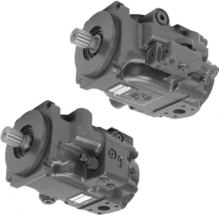
3 Series 45 Frame G and H Open Circuit Axial Piston Pumps Service Manual
4 Introduction 1. Introduction 1.1 Using This Manual This manual includes information for the normal operation, maintenance, and service of the Series 45 family of open circuit pumps. The manual includes a description of the units and their individual components, troubleshooting information, adjustment instructions and minor repair procedures. Unit warranty obligations should not be affected if maintenance, adjustment and minor repairs are performed according to the procedures described in this manual. Many service and adjustment activities can be performed without removing the unit from the vehicle or machine. However, adequate access to the unit must be available, and the unit must be thoroughly cleaned 1.2 Safety Precautions Always consider safety precautions before beginning a service procedure. Protect yourself and others from injury. Disable Work Function WARNING Certain service procedures may require the vehicle / machine to be disabled (wheels raised off the ground, work function disconnected, etc.) while performing them in order to prevent injury to the technician and bystanders. Flammable Cleaning Solvents WARNING Some cleaning solvents are flammable. To avoid possible fire, do not use cleaning solvents in an area where a source of ignition may be present. before beginning maintenance, adjustment, or repair activities. Since dirt and contamination are the greatest enemies of any type of hydraulic equipment, cleanliness requirements must be strictly followed. This is especially important when changing the system filter and during adjustment and repair activities. A worldwide network of Sauer-Sundstrand Authorized Service Centers is available should repairs be needed. Contact any Sauer-Sundstrand Authorized Service Center for details. A list of all Service Centers can be found in bulletin BLN , or in brochure SAW (Ident. No ). The following general precautions should be taken into consideration whenever servicing a hydrostatic system. Fluid Under High Pressure WARNING Use caution when dealing with hydraulic fluid under pressure. Escaping hydraulic fluid under pressure can have sufficient force to penetrate your skin causing serious injury. This fluid may also be hot enough to cause burns. Serious infection or reactions can develop if proper medical treatment is not administered immediately. Personal Safety WARNING Proper safety equipment, including safety glasses, should be used at all times. Copyright 1999, Sauer-Sundstrand Company, All Rights Reserved. 2 Printed in U.S.A. 0899H
5 Introduction Contents 1. Introduction Using This Manual Safety Precautions Symbols Used in Sauer-Sundstrand Literature Functional Description General Description and Cross Sectional Views Open Circuit Pump Design Basic Pump Operation The System Circuit Pump Features Displacement Limiters Auxiliary Mounting Pads Input Shafts Pump Control Options Pressure Compensator (PC) Control Load Sensing (LS) Control Technical Specifications General Specifications Design Type of Mounting Auxiliary Mounting Pad Options Control Options Port Connections Direction of Rotation Installation Position Circuit Diagrams Hydraulic Parameters Inlet Pressure Pressure Compensator Valve Setting Case Pressure Hydraulic Fluid Temperature Range Fluid Viscosity Limits Filtration Technical Data Pressure Measurement Required Tools Port Locations and Pressure Gauge Installation cc Frame Size cc Frame Size Initial Start-up Procedures Fluid and Filter Maintenance Troubleshooting Excessive Noise and / or Vibration System Operating Hot Actuator Response is Sluggish Low Pump Output Flow Pressure Compensator Not Reaching PC Setting High Inlet Vacuum Pressure or Flow Instability
6 Introduction Contents (continued) 8. Adjustments Pressure Compensator (PC) Control Adjustments cc Frame Size cc Frame Size Load Sensing (LS or LB) Control Adjustment cc Frame Size cc Frame Size Displacement Limiter Adjustment Minor Repair Instructions Shaft Seal Replacement Displacement Piston and Maximum Displacement Limiter Bias Piston Auxiliary Pads Control Personality Conversion, 57cc Only Pressure Compensator (PC) Control Pilot Stage and Gain Orifice cc Frame Size cc Frame Size Load Sensing (LS or LB) Control or Pressure Compensator (PC) Second Stage cc Frame Size cc Frame Size Plug and Fitting Torques cc Frame Size cc Frame Size Exploded Views cc Frame Size cc Frame Size Auxiliary Pad Adapters
7 Introduction 1.3 Symbols Used in Sauer-Sundstrand Literature DANGER! May result in injury. May result in immediate or premature damage. Lubricate with hydraulic fluid. Apply grease / petroleum jelly. Reusable part Nonreusable part, use a new part. Non-removable item OR in drawing either option may exist. Measurement required. Flatness specification Parallelism specification External hex head Internal hex head Torx head Tip, helpful suggestion The symbols above can be found in the illustrations and text of this manual. They are intended to communicate helpful information at the point where it is most useful to the reader. Apply locking compound. Inspect for wear or damage. Clean area or part. Be careful not to scratch or damage. Note correct orientation. Mark orientation for reinstallation. Torque specification Press in. Pull out with tool. Use installation sleeve / cone "bullet". In most instances, the appearance of the symbol itself denotes its meaning. The legend above is provided to define each symbol and explain its purpose. 5
8 Functional Description 2. Functional Description 2.1 General Description and Cross Sectional Views Open Circuit Pump Design Sauer-Sundstrand Series 45 open circuit pumps convert input torque into hydraulic power. A rotating cylinder block containing axial pistons which are forced in and out of their bores by the angle of a swashplate, results in a specific amount of fluid being displaced for every revolution of the cylinder block. The displacement per revolution will change as the swashplate angle changes. The swashplate angle is controlled by the displacement piston. The bias piston acts to return the pump swashplate to max angle. Tappered Roller Bearing Displacement Piston Swashplate The slipper attaches to the end of the piston by means of a ball and socket joint. This allows the slipper to tilt at any angle while maintaining contact with the swashplate. The face of the slipper pad slides on a hydrostatic fluid film which uses fluid pressure to balance internal forces. Cylinder Block Kit Tappered Roller Bearing Shaft Seal Valve Plate Slipper Bias Piston Piston P E 6
9 Functional Description 2.1 General Description and Cross Sectional Views (continued) Basic Pump Operation Series 45 pumps utilize a cradle swashplate design with a hydraulic control piston. Control is provided through a built-in compensator valve. This compensator will shift the pump displacement from maximum to minimum when the set pressure is reached. Controls are also available 2.2 The System Circuit The pump receives fluid directly from the reservoir without the requirement of a charge pump. Fluid is then pumped under pressure to the system and returns directly to the reservoir. The speed of the actuator (cylinder, hydraulic motor, etc.) depends on the volume of fluid being pumped. The operating pressure depends on the actuator load. If the actuator is to be reversed, a direction control valve is necessary as the pump swashplate operates on one side of neutral only and the pump is unidirectional. B X for remote compensators and load sensing systems. An available displacement adjustment screw allows the maximum flow to be adjusted to match system requirements. These controls are designed for low hysteresis and responsive performance. When the pump s automatic control is activated, fluid is ported to the displacement piston. This action destrokes the swashplate (reduces pump displacement) to obtain the desired pump flow. The control can position the swashplate at any angle between it s maximum and zero displacement to provide the pump flow necessary to maintain the setting of the control. From System Heat Exchanger Return Filter To System M2 L1, L2 S M4 P E 7
10 Functional Description 2.3 Pump Features To meet the requirements of various applications, the Series 45 pumps are available with various options which change the operation of the pump. Adjustment Screw Displacement Limiters Series 45 pumps are available with an optional maximum displacement limiter. This mechanical stop can limit the maximum displacement of the pump to any value from maximum to 75% displacement Auxiliary Mounting Pads Auxiliary mounting pads are available for all radial ported Series 45 pumps. These pads are typically used for mounting auxiliary hydraulic pumps. Since the auxiliary pad operates under case pressure, an o-ring must be used to seal the auxiliary pump mounting flange to the pad. The driving coupling is lubricated by oil from the main pump case. Lock Nut P E P Input Shafts Series 45 pumps are available with a variety of splined, straight keyed, and tapered end shafts. 8
11 Functional Description 2.5 Pump Control Options Pressure Compensator (PC) Control The pressure compensator control is designed to maintain a constant pressure in the hydraulic circuit as flow varies. When the system pressure at the pump outlet drops below the compensator setting, the control will increase the pump displacement to maximum (maximum flow). Once the system pressure reaches the compensator setting, the control will regulate pump displacement to produce an output flow which will maintain system pressure at the compensator setting. The pressure compensator setting is adjustable. The setting range for the pressure compensator is from 100 to 280 bar [1450 to 4060 psi]. Refer to Section 8, page 22, for adjustment procedures. Note: On 57cc pumps built after serial number A XXXXX, tamper resistant hardware is installed on the PC & second stage adjustment screws. This will allow only one complete clockwise turn from the original factory setting. 57 cc Second Stage Adjustment Screw 2 nd Gain - bar [psi] per turn 57 cc 74 cc P C [1290] [610] S tage [260] PC Adjustment Screw 74 cc PC Adjustment Screw T E P E 9
12 Functional Description 2.5 Pump Control Options (continued) Load Sensing (LS) Control The load sensing control is designed to match pump outlet flow and pressure with system demand. When the control valve is centered, the load sensing port on the pump is drained to the reservoir through a bleed orifice located either in the control valve or the pump housing. This maintains a standby pressure at the pump outlet equal to the load sense setting. When the external control valve is actuated, the load sensing port sees the load pressure. The pump control then adjusts the pump output flow to maintain a constant pressure drop (equal to the load sensing setting) across the external control valve. The pump thereby provides flow to the load as demanded by the external control valve position. The load sensing setting is adjustable. The setting range for the load sensing control is from 10 to 30 bar [145 to 435 psi]. Refer to section 8, page 24, for adjustment procedures. 57 cc LS Port LS Adjustment Screw Gain - bar [psi] per turn 57 cc 74 cc P C [1290] [610] L S [260] [250] T E Note: On 57cc pumps built after serial number A XXXXX, tamper resistant hardware is installed on both the PC & LS adjustment screws. This will allow only one complete counter clockwise turn from original factory setting. PC Adjustment Screw 74 cc LS Port PC Adjustment Screw P E 10
13 Technical Specifications 3.1 General Specifications Design Open circuit axial piston pumps of cradle swashplate design with variable displacement Type of Mounting SAE flange, Size C (SAE J744) mounting pad SAE flange, Size B optional for 57cc pump only Auxiliary Mounting Pad Options SAE flange, Size A, B, B-B, or C Control Options PC: Pressure Compensator LS: Load Sensing (with Pressure Compensator) 3.2 Circuit Diagrams Series cc variable displacement pump with pressure compensator / load sensing control M2 L1,L2 B S 3. Technical Specifications * X Port Connections Inlet and pressure ports: SAE Flange Ports, Code 61 Axial (end) ports or radial (side) ports All other: SAE straight thread o-ring boss Direction of Rotation Clockwise or counterclockwise Installation Position Installation position discretionary. The housing must always be filled with hydraulic fluid. Series cc variable displacement pump with pressure compensator / load sensing control *optional M4 L1,L2 S *optional P P M2 B * X M4 Ports: B = Main pressure line S = Suction line L1, L2 = Case drain lines X = Load sense line M2 = Gauge port for port "B" M4 = Gauge port - servo pressure Ports: B = Main pressure line S = Suction line L1, L2 = Case drain lines X = Load sense line M2 = Gauge port for port "B" M4 = Gauge port - servo pressure 11
14 Technical Specifications 3.3 Hydraulic Parameters Inlet Pressure Minimum pressure, continuous = 0.8 bar absolute [23.2 in Hg] (at reduced maximum pump speed) Minimum pressure, cold start = 0.5 bar absolute [14.8 in Hg] Pressure Compensator Valve Setting Minimum pressure: 100 bar [1450 psi] Maximum pressure: 280 bar [4060 psi] Case Pressure Maximum continuous: 0.5 bar [7 psi] Above inlet Intermittent: 2 bar [29 psi] Cold start Hydraulic Fluid Refer to Sauer-Sundstrand publication BLN-9887 or Refer to publication ATI-E 9101 for information relating to biodegradable fluids Temperature Range 1 Intermittent, cold start = - 40 C [- 40 F] Continuous = 82 C [180 F] Maximum = 104 C [220 F] (at the hottest point, i.e. drain line) 1. Hydraulic fluid viscosity must be maintained within the prescribed limits Fluid Viscosity Limits mm 2 /s (cst) SUS (Saybolt Universal Seconds) n min = 9 58 min. continuous n min = intermittent n max = max. continuous n max = intermittent, cold start Filtration Required cleanliness level: ISO 4406 Class 18/13 or better. Refer to Sauer-Sundstrand publication BLN or and ATI-E
15 Technical Specifications 3.4 Technical Data Input Speed * Refer to General Technical Specifications in Series 45 Axial Piston Open Circuit Pumps Technical Information Manual, BLN ** With pressurized inlet. Displacement Minimum Rated* Maximum* Dimension Frame Size cm 3 [ in 3 ] 57 [3.48] 74 [4.52] min - 1 ( rpm) min - 1 ( rpm) min - 1 ( rpm) 3200* * 2800* * M aximum (Peak) Working Pressure b ar [psi] 350 [5075] 350 [5075] C ontinuous Working Pressure b ar [psi] 280 [4060] 280 [4060] Flow at Rated Speed Theoretical Input Torque at Maximum Displacement Mass Moment of Inertia of the Internal Rotating Parts Weight l/min [US gal/min] Nm/bar [lbf in/1000 psi] 2 kg m [ lbf ft 2 ] [39.5] [554] [0.1014] [47.4] [720] [0.1500] A xial Ported Units k g [lb] 24 [53] 29 [63] R adial Ported Units k g [lb] 27 [60] 36 [80] T E 13
16 4.1 Required Tools 4. Pressure Measurement Pressure Measurement The service procedures described in this manual for Series 45 pumps can be performed using common mechanic s hand tools. Special tools, if required are shown. Pressure gauges should be calibrated frequently to ensure accuracy. Snubbers are recommended to protect pressure gauges. 4.2 Port Locations and Pressure Gauge Installation The following sections list the gauge ports for each frame size. The recommended pressure gauge and fitting are also specified. Outline drawings showing port locations follow the tables cc Frame Size M2 System 300 bar or 5000 psi gauge Pressure 7/16 20 o-ring Fitting M4 Control 300 bar or 5000 psi gauge Piston 7/16 20 o-ring Fitting Case Drain Port L2 Remote PC Signal Servo Pressure Gauge Port Port M4 L1 Case 10 bar or 100 psi gauge L2 Pressure 7/8 14 o-ring Fitting (057) X1 LS Signal 300 bar or 5000 psi gauge Tee into LS Signal Line 7/16 20 o-ring Fitting LS Signal Port X* *This port is plugged on pumps with PC control System Output Port B System Inlet Port S Case Drain Port L1 System Pressure Gauge Port Port M2 Base Unit Shown with PC / LS Control and Axial End Cap Ports (LH Rotation) P E 14
17 Pressure Measurement 4.2 Port Locations and Pressure Gauge Installation (continued) cc Frame Size M2 System 300 bar or 5000 psi gauge Pressure 7/16 20 o-ring Fitting M4 Control 300 bar or 5000 psi gauge Piston 7/16 20 o-ring Fitting Case Drain Port L1 LS Signal Port X LS Signal Port X1 Servo Pressure Gauge Port Port M4 System Pressure Gauge Port Port M2 L1 Case 10 bar or 100 psi gauge L2 Pressure 7/8 14 o-ring Fitting (074) X1 LS Signal 300 bar or 5000 psi gauge Tee into LS Signal Line 7/16 20 o-ring Fitting Case Drain Port L2 Base Unit with PC/LS Control and Axial End Cap Ports Shown P E 15
18 Initial Start-up Procedures 5. Initial Start-up Procedures The following start-up procedure should always be followed when starting-up a new Series 45 installation or when restarting an installation in which the pump has been removed. The inlet line leading from the pump to the reservoir must be filled prior to start up. Check inlet line for properly tightened fittings and be certain it is free of restrictions and air leaks. WARNING The following procedure may require the vehicle/machine to be disabled (wheels raised off the ground, work function disconnected, etc.) while performing the procedure in order to prevent injury to the technician and bystanders. Take necessary safety precautions before moving the vehicle/machine. Prior to installing the pump, inspect the units for damage incurred during shipping and handling. Make certain all system components (reservoir, hoses, valves, fittings, heat exchanger, etc.) are clean prior to filling with fluid. The pump should be connected to the prime mover so that the centers of both shafts are aligned. Incorrect alignment may result in eventual damage to the drive shaft, drive shaft bearings, or the drive shaft seal which can cause external oil leakage. Fill the main pump housing with clean hydraulic fluid prior to start up. Fill by pouring filtered oil directly into the upper most case drain hole. Fill the reservoir with recommended hydraulic fluid. Fluid should always be filtered through a 25 micron filter prior to entering the reservoir. Never reuse hydraulic fluid. To ensure the pump stays filled with oil, the case drain line should be installed in the upper most case drain port. Follow recommendations in the vehicle / machine operator s manual for prime mover start up procedures. Install a gauge at port M2 to monitor system pressure during start up. Jog the prime mover or run at the lowest possible speed until system pressure builds to normal levels (minimum 11 bar [160psi]). Once system pressure is established, increase the speed to full operating RPM. If system pressure is not maintained, shut down the prime mover, determine the cause, and take corrective action. Refer to Troubleshooting, page 18. Operate the hydraulic system for at least fifteen (15) minutes under light load conditions. It may be necessary to check and adjust control settings after installation. Refer to Adjustments, page 22. Shut down the prime mover and remove the pressure gauge. Check the fluid level in the reservoir, add if necessary. The pump is now ready for operation. 16
19 Fluid and Filter Maintenance 6. Fluid and Filter Maintenance To ensure optimum service life of Series 45 products, regular maintenance of the fluid and filter must be performed. Contaminated fluid is the main cause of unit failure. Care should be taken to maintain fluid cleanliness while performing any service procedure. Check the reservoir daily for proper fluid level, the presence of water (noted by a cloudy to milky appearance or free water in the bottom of the reservoir), and rancid fluid odor (indicating excessive heat). If either of these conditions occur change the fluid and filter immediately. It is recommended that the fluid and filter be changed per the vehicle / machine manufacturer s recommendations or at the following intervals: Reservoir Type Sealed Breather Maximum Oil Change Interval 2000 Hours 500 Hours T E It may be necessary to change the fluid more frequently if it becomes contaminated with foreign matter (dirt, water, grease, etc.) or if the fluid has been subjected to temperature levels greater that the recommended maximum. Never reuse hydraulic fluid. Dispose of used hydraulic fluid properly. Filters should be changed whenever the fluid is changed or whenever the filter indicator shows that it is necessary to change the filter. Replace all fluid lost during filter change. 17
20 Troubleshooting 7.1 Excessive Noise and / or Vibration 7. Troubleshooting Item 1. Check oil in reservoir. Description Insufficient hydraulic fluid will lead to cavitation. Action Fill the reservoir to proper level. 2. Check for air in system. 3. Check pump inlet pressure / vacuum. 4. Inspect shaft couplings. 5. Inspect shaft alignment. 6. Hydraulic oil improper viscosity. 7.2 System Operating Hot Item Description Action 1. Check oil in reservoir. Insufficient amount of hydraulic oil Fill the reservoir to proper level. Verify will not meet cooling demands of proper size of reservoir. system. 2. Inspect heat exchanger. 3. Check external system relief valve setting. 4. Check pump inlet pressure/vacuum. 7.3 Actuator Response is Sluggish 1. Check external system relief valve setting. Noisy, erratic control. Erratic behavior, low output flow. A loose or incorrect shaft coupling will cause excessive noise and/or vibration. Misaligned shafts will create excessive frictional noise and/or vibration. Hydraulic oil viscosity above acceptable limits will cause cavitation at start up. Heat exchanger not sufficiently cooling system. Relief valve setting below PC setting will create heat. High inlet vacuum will create heat. Low external relief valve setting will slow down system. Purge air and tighten fittings. Check inlet for leaks. Correct pump inlet pressure / vacuum conditions. Repair or replace coupling and check that correct coupling is being used. Correct shaft misalignment. Replace existing fluid with the appropriate viscosity grade fluid. See Hydraulic Fluids, Series 45 Technical Information Manual, BLN Check air flow and input air temperature for the heat exchanger. Clean, repair, or replace heat exchanger. Verify proper size of heat exchanger. Adjust external system relief valve setting. Correct inlet pressure / vacuum conditions. Item Description Action Adjust external relief valve setting. 2. Check PC and LS control setting. 3. Check LS control signal pressures. 4. PC control not operating properly. 18 Low PC setting will prevent the pump from achieving full stroke. Incorrect LS signal will not allow pump to operate correctly. PC control with abnormal wear or contamination will not operate properly. Adjust PC and LS setting. Inspect system, ensure that proper LS signal is transmitted to the pump. Flush screen in PC cartridge to remove contamination or replace abnormally worn spool.
21 Troubleshooting 7.3 Actuator Response is Sluggish (continued) Item Description Action 5. Internal system leaks. Worn internal parts will not allow the Repair as required. pump to operate properly. 6. Hydraulic oil viscosity above acceptable limits. 7. Check system valving. 8. Check pump case pressure. 9. Check pump inlet pressure High inlet vacuum will cause cavita- Correct inlet pressure conditions. / vacuum. tion and generate heat. 7.4 Low Pump Output Flow Item Description Action 1. Check oil in reservoir. Insufficient hydraulic oil level. Fill the reservoir to proper level. 2. Hydraulic oil viscosity above acceptable limits. 3. Check external system relief valve setting. 4. Check PC and LS control setting. 5. Check pump inlet pressure / vacuum. 6. Check input speed. 7. Check pump displacement limiter. Oil viscosity above acceptable limits or low oil temperature will not allow the pump to fill or control to operate properly. Malfunctioning valve may not allow system to respond. High case pressure will cause the system to be sluggish. Oil viscosity above acceptable limits or low oil temperature will not allow the pump to fill or control to operate properly. External relief valve set below PC setting will cause low flow. Low PC setting will prevent the pump from achieving full stroke. Low LS setting will prevent adequate flow. High inlet vacuum will cause cavitation and decrease flow. Low input speeds decrease flow. Pump displacement limiter may be set below desired flow rate. Allow system to warm up before operation or use fluid with the appropriate viscosity grade for expected operating temperatures. See Hydraulic Fluids, Series 45 Technical Information Manual, BLN Repair or replace system valving. Correct case drain line restrictions. Allow system to warm up before operation or use fluid with the appropriate viscosity grade for expected operating temperatures. See Hydraulic Fluids, Series 45 Technical Information Manual, BLN Correct external relief valve setting. Adjust PC and LS setting. See Adjustments, page 22. Correct inlet pressure conditions. Adjust input speed. Adjust displacement limiter to the appropriate setting. See Adjustments, page Check pump rotation. 9. Check pilot orifice in port X. 10. Verify bleed orifice plug is installed (serial numbers prior to A XXXX). Incorrect rotational configuration will cause low flow. Restricted control orifice will limit output flow. If plug is missing, control will not perform correctly. Use pump with appropriate rotational configuration. Inspect and clean control orifice. Install bleed orifice plug (C111). See Minor Repair page
22 Troubleshooting 7.5 Pressure Compensator Not Reaching PC Setting Item Description Action 1. Check PC control setting. Pump will not compensate to pressure Adjust PC to appropriate setting. settings. 2. Check external relief valve. PC control cannot be set above an external relief valve setting. Adjust the external relief valve to the appropriate setting. 3. Inspect compensator spring. 4. Inspect PC poppet (57cc), or spool (74cc) for wear. 5. Inspect compensator spool. 6. Check PC control for contamination. 7. Verify bleed orifice plug is installed (serial numbers prior to A XXXX). Replace spring. Replace PC cartridge or spool. Correct orientation of spool. Clean PC control components and rid system of contamination. Install bleed orifice plug (C111). See Minor Repair page High Inlet Vacuum Item Description Action 1. Check oil temperature. Cold oil has a higher viscosity. Allow system to warm up before operation. 2. Inspect inlet screen. 3. Check inlet piping. 4. Hydraulic oil improper viscosity. Broken, damaged, or missing spring will cause erratic operation. Abnormal wear of the PC poppet or spool will allow internal leakage in the control. Improper orientation will result in poor operation. Spool or poppet is held open by contaminants. If plug is missing, control will not perform correctly. Restriction will cause high vacuum. Too many fittings, bends, or long piping will cause high vacuum. Hydraulic oil viscosity above acceptable limits will cause cavitation. Remove restriction / blockage. Eliminate fittings to make path more direct. Replace existing fluid with the appropriate viscosity grade fluid. See Hydraulic Fluids, Series 45 Technical Information Manual, BLN Pressure or Flow Instability Item Description Action 1. Air in system. Air in system will cause erratic Activate PC, allowing system to bleed operation. air. Check inlet line for leaks. 2. Check control spools. Sticking control spools. Inspect spools for free movement in bore. Clean or replace as needed. 3. Check external relief valve and PC setting. 4. Check external relief valve. 5. Check gain orifice-plug (57 cc only). 20 Insufficient pressure differential between pump and external relief valve. Chattering external relief valves may be causing unstable feedback to pump. Obstructed gain orifice-plug option may cause instability. Adjust external relief valve or PC control settings to appropriate level. Adjust or replace relief valve. Clear or change gain orifice-plug.
23 Troubleshooting Notes: 21
24 Adjustments 8. Adjustments 8.1 Pressure Compensator (PC) Control Adjustments cc Frame Size WARNING Do not make adjustments or disconnect any hoses until all residual pressure in the system circuit has been released. Take necessary precautions to secure the work function of the machine to prevent injury while performing this procedure. The pressure compensator setting is indicated in the pump model code. Refer to the Technical Information Manual BLN for more information. Install a pressure gauge in port M2 to measure system pressure. Install a pressure gauge in drain port L1 or L2 to measure case pressure. If a remote PC control is used, disconnect the signal line, cap it, and plug the port. Refer to Pressure Measurement, page 14. Install a pilot hose (6mm [0.25 in] diameter minimum) at port X connecting to the reservoir to drain the remote PC port. Note: Failure to drain port X (spring cavity) to reservoir may cause additional back pressure on the PC spring, resulting in pressure settings above the desired specification. It is recommended that this procedure be used on all Series 45, 57cc pumps, however it is particularly vital to 1999 and newer units due to hardware changes associated with the PC cartridge. PC Adjustment Screw 13 mm PC Adjustment Seal Lock Nut 13 mm 23 Nm [17 lbf ft] Start the prime mover and run at normal speed. While securing the second stage adjustment screw, loosen the seal locknut. Turn the second stage adjustment screw 1 until a the gauge at port M2 2 reads 15 bar [220psi]. Clockwise rotation of the screw will increase pressure, counterclockwise rotation will decrease. While holding the position of the second stage adjustment screw, torque the seal locknut to 23 Nm [17 lbf ft]. Shut down the prime mover. Disconnect the pilot hose installed at port X and reinstall the plug. Start the prime mover and run at normal speed. Operate a hydraulic function to its full extension, loading the pump at maximum pressure and zero flow. While securing the PC adjustment screw, loosen the seal locknut. Turn the PC adjustment screw 1 until the desired setting is indicated on the pressure gauge at port M2 3. Clockwise rotation will increase pressure, counterclockwise rotation will decrease. If the pressure does not increase, an external system relief valve may need to be adjusted. An external system relief valve should be set above the PC setting for proper operation. While holding the position of the PC adjustment screw, torque the seal locknut to 23 Nm [17 lbf ft]. Stop the prime mover, remove the pressure gauges, and return the system to its normal operating configuration. Port X Remote PC Port Second Stage Adjustment Screw 13 mm Second Stage Adjustment Seal-Lock Nut 13 mm 23 Nm [17 lbf ft] P E 1. Pumps with serial number greater than A XXXX will have tamper resistant hardware installed on both the PC and second stage adjustments. This will only allow one complete clockwise turn from the original factory setting. 2. The second stage setting is referenced to the pressure at port X. During this procedure port X is vented to reservoir. 3. PC setting is referenced to case pressure. Subtract case pressure from system pressure to compute the actual setting. 22
25 Adjustments 8.1 Pressure Compensator (PC) Control Adjustments (continued) cc Frame Size WARNING Do not make adjustments or disconnect any hoses until all residual pressure in the system circuit has been released. Take necessary precautions to secure the work function of the machine to prevent injury while performing this procedure. Install a pressure gauge in port M2 to measure system pressure. Install a pressure gauge in case drain port L1 or L2 to measure case pressure. Refer to Pressure Measurement, page 14. Loosen the PC set screw and turn the adjustment screw counter clockwise to release the spring pressure. Turn until the end of the screw is flush with the housing. PC Set Screw 4mm 6.8 Nm [5 lbf ft] Start the prime mover and allow fluid to reach normal operating temperature. Operate the prime mover at normal speed. Operate a hydraulic function to its full extension, loading the pump at maximum pressure and zero flow. Turn the PC adjustment screw until system pressure reaches the desired value, as indicated on the gauge at port M2 1. Clockwise rotation will increase the setting, counterclockwise rotation will decrease. If the pressure does not increase, an external system relief valve may need adjustment. External system relief valve should be set above the PC setting for proper operation. While holding the position of the PC adjustment screw, torque the setscrew to 6.8 Nm [5 lbf ft]. Stop the prime mover and remove the pressure gauges installed at port M2, and case drain port L1 or L2. Replace the port plugs. PC Adjustment Screw 6mm P E 1. PC setting is referenced to case pressure. Subtract case pressure from system pressure to compute the actual setting. 23
26 Adjustments 8.2 Load Sensing (LS or LB) Control Adjustment cc Frame Size WARNING Do not make adjustments or disconnect any hoses until all residual pressure in the system circuit has been released. Take necessary precautions to secure the work function of the machine to prevent injury while performing this procedure. The LS or LB Setting is indicated in the pump model code. Refer to the Technical Information Manual BLN for more information. Install a pressure gauge in port M2 to measure system pressure. Install a pressure gauge in drain port L1 or L2 to measure case pressure. Install a pressure gauge in the remote PC port. If remote PC is used, temporarily remove the remote PC signal line and cap it. Leave the LS signal line connected. Refer to Pressure Measurement, page 14. Start the prime mover and allow fluid to reach normal operating temperature. While securing the LS adjustment screw, loosen the seal locknut. Slowly operate a hydraulic function which will demand approximately half flow from the PC Adjustment Screw 13 mm PC Adjustment Seal Lock Nut 13 mm 23 Nm [17 lbf ft] Port X LS Signal pump, but keep the system pressure below the PC set point. While watching the pressure gauges, turn the LS adjustment screw 1 until the desired pressure differential between port M2 (system pressure) and the remote PC port (LS signal) is achieved 2. Clockwise rotation will increase the setting, counterclockwise rotation will decrease. While holding the position of the adjustment screw, torque the seal locknut to 23 Nm [27 lbf ft]. Operate a hydraulic function to its full extension loading the pump at maximum pressure and zero flow. While securing the PC adjustment screw, loosen the seal locknut. Turn the PC adjustment screw 1 until the desired setting is indicated on the pressure gauge at port M2 3. Clockwise rotation will increase the setting, counterclockwise rotation will decrease. If the pressure does not increase, an external system relief valve may need to be adjusted. External system relief valve should be set above the PC setting for proper operation. While holding the position of the PC adjustment screw, torque the seal locknut to 23 Nm [17 lbf ft]. Stop the prime mover, remove the pressure gauges, and return the system to its normal operating configuration. Remote PC Port LS Adjustment Screw 13 mm LS Adjustment Seal-Lock Nut 13 mm 23 Nm [17 lbf ft] P E 1. Pumps with serial number greater than A XXXX will have tamper resistant hardware installed on both the PC and second stage adjustments. This will only allow one complete clockwise turn from the original factory setting. 2. The LS setting is a differential pressure. Subtract pilot pressure at the remote PC port from system pressure at port M2 to compute the actual setting. 3. PC setting is referenced to case pressure. Subtract case pressure from system pressure to compute the actual setting. 24
27 Adjustments 8.2 Load Sensing (LS or LB) Control Adjustment (continued) cc Frame Size WARNING Do not make adjustments or disconnect any hoses until all residual pressure in the system circuit has been released. Take necessary precautions to secure the work function of the machine to prevent injury while performing this procedure. Port X 3/16 in 12 Nm (9 lbf ft) PC Locking Set Screw 4mm 6.8 Nm (5 lbf ft) PC Adjustment Screw 6 mm The LS or LB Setting is indicated in the pump model code. Refer to the Technical Information Manual, BLN for more information. Install a pressure gauge in port M2 to measure system pressure. Install a pressure gauge in drain port L1 or L2 to measure case pressure. Install a pressure gauge in port X to measure LS signal pressure. Leave the LS signal line connected, using the opposite port for the gauge. Refer to Pressure Measurement, page 14. Start the prime mover and allow fluid to reach normal operating temperature. Loosen the LS locking set screw. Slowly operate a hydraulic function which will demand approximately half flow from the pump, but keep the system pressure below the PC set point. While watching the pressure gauges, turn the LS adjustment screw until the desired pressure differential between port M2 (system pressure) and port X (LS signal) is achieved 1. Clockwise rotation will increase the setting, counterclockwise rotation will decrease. While holding the position of the adjustment screw, torque the locking set screw to 6.8 Nm [5 lbf ft]. Operate a hydraulic function to its full extension loading the pump at maximum pressure and zero flow. While securing the PC adjustment screw, loosen the seal locknut. Turn the PC adjustment screw until the desired setting is indicated on the pressure gauge at port M2 2. Clockwise rotation will increase the setting, counterclockwise rotation will decrease. If the pressure does not increase, an external system relief valve may need to be adjusted. External system relief valve should be set above the PC setting for proper operation. While holding the position of the PC adjustment screw, torque the locking set screw to 6.8 Nm [5 lbf ft]. Stop the prime mover, remove the pressure gauges, and return the system to its normal operating configuration. LS Locking Set Screw 4mm 6.8 Nm (5 lbf ft) LS Adjustment Screw 6 mm P E 1. The LS setting is a differential pressure. Subtract pilot pressure at port X from system pressure at port M2 to compute the actual setting. 2. PC setting is referenced to case pressure. Subtract case pressure from system pressure to compute the actual setting. 25
28 Adjustments 8.3 Displacement Limiter Adjustment If equipped, the displacement limiter may be adjusted to achieve a desired maximum flow rate. The preferred method for setting the displacement limiter is to make adjustments while operating the pump at full stroke on an appropriate test apparatus equipped with a flow meter and system pressure gauge. This allows the pump to be set to a specific maximum flow rate under precise speed and pressure conditions. If test apparatus is not available, the following procedure may be used to set an approximate maximum displacement. Remember to verify that the displacement setting is appropriate by operating the pump in its application after adjustment. To adjust the displacement limiter setting remove the displacement piston bore plug with its o-ring. Loosen the seal locknut and turn the displacement limiter adjustment screw counter clockwise until the opposite end is flush with end of the displacement piston bore plug. The setting is now at maximum displacement. Replace the o-ring and install the plug into the pump housing. Torque the displacement piston plug as indicated. Displacement Piston Bore Plug See Table Displacement Limiter Adjustment Screw 6 mm Seal Locknut 19 mm 87 Nm [64 lbf ft] Turn the displacement limiter adjustment screw clockwise to set the desired maximum displacement. For 57cc pumps, the displacement is decreased by 5cc per revolution of the displacement limiter adjustment screw; for 74cc pumps, 6cc per revolution. While holding the position of the displacement limiter adjustment screw, torque the seal locknut. WARNING The seal lock nut must be torqued after every adjustment to prevent an unexpected change in pump output and to prevent external leakage during unit operation. Displacement Piston Bore Plug 57 cc 74 cc Hex Wrench Torque 1 1 / 4 in 1 3 / 8 in 230 Nm [170 lbf ft] [ lbf ft] T E (57 CC Shown) P E 26
29 Adjustments Notes: 27
30 Minor Repair 9.1 Shaft Seal Replacement A lip type shaft seal is used in the Series 45 open circuit variable pumps. This seal can be replaced without major disassembly of the unit. Replacement of the shaft seal requires removal of the pump from the machine. Remove the retaining ring (item K010) from the housing. After removing the retaining ring, carefully remove the shaft seal (item K020) from the bore in the pump housing. The face of the seal may be punctured with a sharp instrument to aid in prying the seal out, or a slide hammer type puller may be used to remove the seal. Care must be taken to avoid damaging the pump housing or shaft. Discard the shaft seal. Inspect the pump housing and the new seal for damage. Inspect the sealing area on the shaft for rust, wear, or contamination. Polish the sealing area on the shaft if necessary. Use a seal protection sleeve or wrap the end of shaft with thin plastic to prevent damage to the seal lip during installation. Lubricate the inside diameter of the new seal with petroleum jelly. Press the new seal into the housing just far enough to clear the retaining ring groove. Keep the shaft seal perpendicular to the shaft. The cupped side of the shaft seal must face the shaft bearing. Do not damage the seal during installation. CAUTION Do not press the seal into the housing farther than necessary to install the retaining ring. The seal must not contact the shaft bearing. 9. Minor Repair Instructions 5.33 mm [.21 in] K010 K020 Using the appropriate snap ring pliers, install the seal retaining ring. P
31 Minor Repair 9.2 Displacement Piston and Maximum Displacement Limiter Remove the displacement piston bore plug (item L020) with its o-ring. Discard the o-ring. Remove the displacement piston (item L010) from the pump housing. If equipped with displacement limiter, loosen the seal lock nut (item L030), remove the nut and limiter screw (item L040) from the displacement piston bore plug (item L020). Inspect the displacement piston for wear or damage. Lubricate the displacement control piston with hydraulic oil and install it into the pump housing with the hole in the end of the piston facing the bore plug. L030 L040 L020 L020 L010 Install a new o-ring on the piston bore plug and, if equipped, install the displacement limiter screw and seal locknut. Adjust the displacement limiter. See Adjustments, page 26. Install the piston bore plug into the pump housing. Torque the displacement piston plug as indicated. WARNING The seal lock nut must be torqued after every adjustment to prevent an unexpected change in pump output and to prevent external leakage during unit operation. (57cc Shown) P E 6 mm 19 mm 87 Nm [64 lbf ft] Displacement Piston Bore Plug L cc 74 cc Hex Wrench Torque 1 1 / 4 in 1 3 / 8 in 230 Nm [170 lbf ft] [ lbf ft] T E 29
32 Minor Repair 9.3 Bias Piston Remove the bias piston guide (item B081) (with the bias spring, bias piston, o-rings and backup washer) from the pump housing. Remove the bias spring (item B083) and bias piston (item B084) from the piston guide. Remove the backup washer (item K110), small o-ring (item K100), and large o-ring (item B082) from the piston guide. Inspect the bias piston, piston guide, and spring for wear or damage. K100 K110 B083 Install new o-rings and a new backup washer on the piston guide. Install the bias spring on the piston guide. Lubricate the bias piston with hydraulic oil and install it onto the piston guide. Install the piston guide assembly into the pump housing and torque as indicated. TIP To keep the bias piston in position during assembly, hold a finger over the hole in the bias piston guide when installing. B084 (57cc Shown) P E B081 B082 B081 Hex Wrench Torque Bias Piston Guide 57 cc 74 cc 1 1 / 4 in 1 3 / 8 in 230 Nm [170 lbf ft] [ lbf ft] T E 30
33 Minor Repair 9.4 Auxiliary Pads If installed, remove the screws retaining the auxiliary pump (not shown), and remove the pump with its sealing o-ring. Discard the o-ring. Remove the drive coupling (item J140). Remove the four screws (item J100) retaining the pad adapter (item J080) to the pump end cap (six screws are used for the SAE C pad). Discard the two pad adapter o-rings (items J090, J095). Install the pad adapter with new o-rings 1. Lubricate o-rings with petroleum jelly before installation. Install and torque the screws to 75 Nm [55 lbf ft]. Install the drive coupling. If equipped, install the auxiliary pump with new o-ring. J080 J090 J100 J140 J mm 75 Nm [55 lbf ft] P E 1. Units with serial number prior to A97-42-XXXX do not use item J
34 Minor Repair 9.5 Control Personality Conversion, 57cc Only On the 57cc pump, control personalities may be easily converted between load sensing (LS) and pressure compensating (PC) options. The conversion steps required are listed below. To convert from PC to LS control option: 1. Remove PC spool (C090) (orificed spool). 2. Install LS spool (C090) (non-orificed spool). 3. Add pilot orifice (G010). (Size varies from.8mm to 1.1 mm) Refer to Service Parts Manual, BLN , for orifice part numbers. C120 3/16 in. 12 Nm [9 lbf ft] C100 (PC) 3/16 in. 12 Nm [9 lbf ft] G010 (LS) 3mm 5 Nm [44 lbf in] Without orifice (LS) or Bleed Land (LB) C111 3mm 5 Nm [44 lbf ft] Refer to Minor Repair, page 35, for instructions on removal and replacement of parts referenced in this procedure. After conversion, check setting and adjust as necessary. See Adjustments, pages 22 and 24. To convert from LS to PC control option: 1. Remove LS spool (C090) (non-orificed spool) 2. Install PC spool (C090) (orificed spool) 3. Remove pilot orifice (G010) C090 7/8 in. 46 Nm [34 lbf ft] With orifice (PC) C080 C070 C060 C050 C040 C030 C010 C010 4mm C110 C020 13mm 23 Nm [17 lbf ft] C130 13mm P E 32
35 Minor Repair 9.6 Pressure Compensator (PC) Control Pilot Stage and Gain Orifice cc Frame Size Remove the PC valve cartridge assembly (with o- rings and backup washer) from the pump housing. Install the cartridge assembly into the pump housing and torque to 37 Nm [27 lbf ft]. Remove and discard the small o-ring (item K080), backup washer (item K090), and large o-ring (item D016) found on the cartridge assembly. Loosen the seal lock nut (item D015) and remove the adjustment screw 1 (item D014), spring (item D013), and poppet (item D012) from the cartridge housing (item D011). Inspect all parts for wear or damage. Install new o-rings and a new backup washer on the cartridge housing. Install the poppet, spring, and adjustment screw (with seal lock nut) into the cartridge housing. PC Valve Cartridge Assembly K080 K090 D106 D011 D012 D013 D015 D014 11/16 in. 37 Nm [27lbf ft] 4mm 13mm D Nm [17 lbf ft] D019 D018 13mm Check and adjust the pressure compensator setting before putting the pump back into operation. See Adjustments, page 22. The control gain orifice plug (item H010) and bleed orifice plug 2 (item C111) may be removed after removing the passage plugs (items K120) in the pump housing. Inspect orifice plugs for blockage, clean as necessary and reassemble. Torque orifice plugs to 5 Nm [44 lbf in], passage plugs to 12 Nm [9 lbf ft]. K120 H010 3mm 4 Nm [44 lbf in] 3/16 in. 12 Nm [9lbf ft] K120 (Not used on remote PC) 2 C111 P E 1. Pumps with serial number greater than A XXXX will have tamper resistant hardware (items D018 and D019) installed on the PC adjustment screw. This will only allow one complete clockwise turn from the original factory setting. 2. Pumps with serial number greater than A XXXX do not use bleed orifice (item C111). The port in the housing is also blocked. 33
36 Minor Repair 9.6 Pressure Compensator (PC) Control Pilot Stage and Gain Orifice (continued) cc Frame Size Remove the set screw (item C102) and the PC adjustment screw (item C138). The control springs (items C134 and C135) and spring seat (item C133) can now be removed from the cavity. Remove the plug (item C103) from the opposite end of the control and remove the control spool (item C132). Note the orientation of the control spool for reassembly. Remove the four control mounting screws (item C300). Remove the control and interface o-rings (items C200) from the housing. Remove the control gain orifice (item H010). Flush the control cavity and wash all parts with clean solvent. Air dry. (C132) (C103) 3/16 12 Nm [9 lbf ft] 4 mm 7 Nm [5 lbf ft] C300 3 mm 5 Nm [3.7 lbf ft] C200 H010 Inspect spool, cavity surfaces, and all parts for wear or damage. Remove any contamination from gain orifice. Replace damaged or worn parts as necessary. Install gain orifice, torque to 5 Nm [3.7 lbf ft]. Install control on pump housing, replacing all o-rings. Install mounting screws, torque to 7 Nm [5 lbf ft]. Install control springs and spring seat in cavity. Install adjustment screw and set screw, torque set screw to 7 Nm [5 lbf ft]. Install control spool and plug, torque to 12 Nm [9 lbf ft]. Verify orientation of spool before installation. Check PC setting and adjust as necessary. See Adjustments, page 23. (C101) 6 mm (C138) (C136) (C134) (C135) (C133) (C102) 4 mm 7 Nm [5 lbf ft] P E 34
Open Circuit Axial Piston Pumps Series 45 Frame K and L
 Service Manual Open Circuit Axial Piston Pumps Series 45 Frame K and L powersolutions.danfoss.com Revision history Table of revisions Date Changed Rev August 2016 Updated tables and Adjustments chapter
Open Circuit Axial Piston Pumps Series 45 Frame K2
 Open Circuit Axial Piston Pumps Series 45 Frame K2 powersolutions.danfoss.com Revision history Table of revisions Date Changed Rev April 2017 First edition 0101 2 Danfoss April 2017 AX00000301en-US0101
PHASED OUT PRODUCT. Series 45 H Frame Open Circuit Axial Piston Pumps. Service Manual
 Series 45 H Frame Open Circuit Axial Piston Pumps Using this manual Organization and headings To help you quickly find information in this manual, the material is divided into sections, topics, subtopics,
Closed Circuit Axial Piston Pumps Series 42 4T
 Service Manual Closed Circuit Axial Piston Pumps Series 42 4T powersolutions.danfoss.com Revision history Table of revisions Date Changed Rev April 2016 correction to port callouts pgs 13 & 37 0202 November
Axial Piston Variable Pumps Series 40 M46 Tandem
 Service Manual Axial Piston Variable Pumps Series 40 M46 Tandem powersolutions.danfoss.com Revision history Table of revisions Date Changed Rev September 2017 minor edit - Displacement limiter torque change
Axial Piston Pumps and Motors Service Manual
 Axial Piston Pumps and Motors Service Manual Introduction Introduction Use of this Manual This manual includes information for the normal operation, maintenance, and servicing of the Series 90 family of
Series 51. Bent Axis Variable Motors Service Manual
 Series 51 Bent Axis Variable Motors Service Manual General Description Series 51 Variable Displacement Motors are bent axis design units, incorporating spherical pistons. These motors are designed primarily
Axial Piston Closed Circuit Pumps Series 42
 MAKING MODERN LIVING POSSIBLE Service Manual Axial Piston Closed Circuit Pumps Series 42 powersolutions.danfoss.com Revision history Table of revisions Date Changed Rev July 2015 Danfoss layout 0300 Nov
Closed Circuit Axial Piston K and L Frame Variable Motors, SAE Mount
 MAKING MODERN LIVING POSSIBLE Service Manual Closed Circuit Axial Piston K and L Frame Variable Motors, SAE Mount powersolutions.danfoss.com Revision history Table of revisions Date Changed Rev November
Bent Axis Motors Series 51 and 51-1
 Bent Axis Motors Series 51 and 51-1 powersolutions.danfoss.com Revision history Table of revisions Date Changed Rev March 2016 minor edit 0202 June 2014 Danfoss layout BA November 2009 correction to defeated
D1 High Power Open Circuit Pumps Size 130/145/193/260
 Service Manual D1 High Power Open Circuit Pumps Size 130/145/193/260 Available only for APAC / EU regions powersolutions.danfoss.com Revision history Table of revisions Date Changed Rev October 2017 Added
Axial Piston Variable Motor Series 40 M46
 MAKING MODERN LIVING POSSIBLE Service Manual Axial Piston Variable Motor Series 40 M46 powersolutions.danfoss.com Revision history Table of revisions Date Changed Rev August 2014 Danfoss Layout BA September
BDU-10/21 Hydrostatic Transmissions Service and Repair Manual
 Hydrostatic Transmissions Service and Repair Manual BLN-50327 January 2018 Table of Contents Table of Contents Description Page Introduction... 3 General Description... 3-5 Fluids... 6 Safety Precautions...
Transit Mixer Axial Piston Pump Size 070/089
 Service Manual Transit Mixer Axial Piston Pump Size 070/089 powersolutions.danfoss.com Revision history Table of revisions Date Changed Rev July 2017 Updated to Engineering Tomorrow 0203 Mar 2014 Converted
Series 20 Axial Piston Pumps. Technical Information
 Series 20 Axial Piston Pumps Technical Information General Description INTRODUCTION Sauer-Danfoss a world leader in hydraulic power systems has developed a family of axial piston pumps. DESCRIPTION Sauer-Danfoss
Cartridge Mount Reverse Displacement Motors (RDM)
") Service Manual Cartridge Mount Reverse Displacement Motors (RDM) powersolutions.danfoss.com Revision history Table of revisions Date Changed Rev May 2016 new housing 0104 February 2015 update Port locations
Service Manual Cartridge Mount Reverse Displacement Motors (RDM) powersolutions.danfoss.com Revision history Table of revisions Date Changed Rev May 2016 new housing 0104 February 2015 update Port locations
Series 20 Axial Piston Pumps. Technical Information
 Series 20 Axial Piston Pumps Technical Information General Description INTRODUCTION Sauer-Danfoss a world leader in hydraulic power systems has developed a family of axial piston pumps. DESCRIPTION Sauer-Danfoss
Closed Circuit Axial Piston Pumps H1 45/53/60/68 Tandem
 Service Manual Closed Circuit Axial Piston Pumps H1 45/53/60/68 Tandem www.danfoss.com Revision history Table of revisions Date Changed Rev June 2018 add angle sensor topics 0303 August 2017 minor edits
H1B 060/080/110/160/210/250 H1 Bent Axis Motors
 H1B 060/080/110/160/210/250 H1 Bent Axis Motors www.danfoss.com Revision history Table of revisions Date Changed Rev August 2018 update adjustment chapter 0504 April 2018 Major layout update, QF080 to
Axial Piston Pumps H1-069/078, 089/100, 115/130, 147/165, 210/250
 Service Manual Axial Piston Pumps H1-069/078, 089/100, 115/130, 147/165, 210/250 www.danfoss.com Revision history Table of revisions Date Changed Rev May 2018 add angle sensor 0308 January 20187 add seal
LDU 20 Closed Circuit Axial Piston Transmission
 Service Manual LDU 20 Closed Circuit Axial Piston Transmission powersolutions.danfoss.com Revision history Table of revisions Date Changed Rev July 2017 Updated to Engineering Tomorrow 0202 March 2014
Axial Piston Pumps DDC20
 Service Manual Axial Piston Pumps DDC20 powersolutions.danfoss.com Revision history Table of revisions Date Changed Rev August 2017 change charge pump housing 0302 March 2015 add implement pump option
Closed Circuit Axial Piston Pumps H1-045/053/060/068
 Service Manual Closed Circuit Axial Piston Pumps H1-045/053/060/068 www.danfoss.com Revision history Table of revisions Date Changed Rev April 2018 add EDC with angle sensor 0303 September 2014 add MDC
Axial Piston Pumps DDC20
 MAKING MODERN LIVING POSSIBLE Service Manual Axial Piston Pumps DDC20 powersolutions.danfoss.com Revision history Table of revisions Date Changed Rev March 2015 add implement pump option CA March 2014
Series 42 Axial Piston Pumps Service Instructions
 Axial Piston Pumps Service Instructions Introduction 1. Introduction 1.1 Using This Manual The Adjustment and Minor Repair procedures detailed herein may be performed by trained personnel without voiding
Series 45 Open Circuit Axial Piston Pumps. Technical Information. Displacement Piston. Swashplate. Piston. Tapered Roller Bearing
 Series 45 Open Circuit Axial Piston Pumps Technical Information Displacement Piston Piston Swashplate Tapered Roller earing Tapered Roller earing Valve Plate Cylinder lock Kit Shaft Seal General Description
INSTRUCTION MANUAL INTERNAL GEAR PUMP TITAN G-4124A SERIES=> FLANGED TITAN G-124A SERIES => FLANGED MODELS:
 INSTRUCTION MANUAL INTERNAL GEAR PUMP TITAN G-4124A SERIES=> FLANGED TITAN G-124A SERIES => FLANGED MODELS: G-H, G-HL, G-K, G-KK, G-L, G-LQ, G-LL, GLS, G-Q, G-QS 1 Contents Maintenance Thrust bearing adjustment
Series 51 - HZ, HA, HB, HE, HS, H1, H2, K1, K2, HP, HC, J1, J2, J3, J4, JA Hydraulic Proportional Controls
 MAKING MODERN LIVING POSSIBLE Service Manual Series 51 - HZ, HA, HB, HE, HS, H1, H2, K1, K2, HP, HC, J1, J2, J3, J4, JA Hydraulic Proportional Controls powersolutions.danfoss.com Revision history Table
HYDRAULICS. TX420 & & lower. Hydraulic Tandem Pump Removal. 4. Remove the LH side panel (Fig. 0388).
.") TX420 & 425 240000299 & lower 4. Remove the LH side panel (Fig. 0388). Hydraulic Tandem Pump Removal Note: Cleanliness is a key factor in a successful repair of any hydraulic system. Thoroughly clean all
TX420 & 425 240000299 & lower 4. Remove the LH side panel (Fig. 0388). Hydraulic Tandem Pump Removal Note: Cleanliness is a key factor in a successful repair of any hydraulic system. Thoroughly clean all
Vickers. Overhaul Manual. Vane Pumps. Small and Large Series Combination Pumps VC(K)(S)-**-(*)*D*-6(1) VC(K)(S)-**-(*)-*-*D*-5(1)
(S)-**-(*)*D*-6(1) VC(K)(S)-**-(*)-*-*D*-5(1)") Overhaul Manual Vickers Vane Pumps Small and Large Series Combination Pumps VC(K)(S)-**-(*)*D*-6(1) VC(K)(S)-**-(*)-*-*D*-5(1) Revised 12/1/86 I-3150-S Table of Contents Section I. Introduction................................................................................
Overhaul Manual Vickers Vane Pumps Small and Large Series Combination Pumps VC(K)(S)-**-(*)*D*-6(1) VC(K)(S)-**-(*)-*-*D*-5(1) Revised 12/1/86 I-3150-S Table of Contents Section I. Introduction................................................................................
Variable Displacement Pumps MP1
 Service Manual Variable Displacement Pumps powersolutions.danfoss.com Revision history Table of revisions Date Changed Rev January 2018 update control current table 0106 November 2017 Add NFPE 0105 October
Series TMM Axial Piston Motor. Technical Information
 Series TMM Axial Piston Motor Technical Information General Description GENERAL DESCRIPTION These motors are designed primarily to be combined with other products in closed circuit systems to transfer
TWO-STAGE HYDRAULIC PUMP. RWP55-IBT-Air
 ORIGINAL INSTRUCTIONS Form No.1000458 5 SPX Corporation 5885 11th Street Rockford, IL 61109-3699 USA Tech. Services: (800) 477-8326 Fax: (800) 765-8326 Order Entry: (800) 541-1418 Fax: (800) 288-7031 Internet
L Hydrostatic Drive Axle Service and Repair Manual
 210-2500L Hydrostatic Drive Axle Service and Repair Manual BLN-50308 January 2018 Service & Repair Manual Table of Contents Description Table of Contents Introduction General Description Technical Specifications
TPV Variable Displacement Closed Loop System Axial Piston Pump THE PRODUCTION LINE OF HANSA-TMP HT 16 / M / 851 / 0813 / E
 HYDRAULIC COMPONENTS HYDROSTATIC TRANSMISSIONS GEARBOXES - ACCESSORIES THE PRODUCTION LINE OF HANSA-TMP Variable Displacement Closed Loop System CONTENTS General Information... Order Code... Manual Control
Series 20 Axial Piston Motors. Technical Information
 Series 20 xial Piston Motors Technical Information General Description INTRODUCTION Sauer-Danfoss a world leader in hydraulic power systems has developed a family of axial piston motors. DESCRIPTION Sauer-Danfoss
AIR/HYDRAULIC INJECTION GUN MODEL INSTRUCTIONS
 I. OPERATION & DESCRIPTION The Air / Hydraulic Injection Gun is a high-pressure tool that should be used with caution and according to these instructions. IMPORTANT: The Gun is 0,000 psi rated. Do not
WALKIE HIGH LIFT HYDRAULIC SYSTEM
 WALKIE HIGH LIFT HYDRAULIC SYSTEM W30-40ZA [B453]; W20-30ZR [B455]; W25-30-40ZC [B454] PART NO. 1524251 2000 SRM 1025 SAFETY PRECAUTIONS MAINTENANCE AND REPAIR When lifting parts or assemblies, make sure
Vane Pumps. VMQ Series Vane Pumps For Industrial and Mobile Applications Displacements to 215 cm 3/ r (13.12 in 3 /r) Pressures to 260 bar (3800 psi)
 Pressures to 260 bar (3800 psi)") Vickers Vane Pumps VMQ Series Vane Pumps For Industrial and Mobile Applications Displacements to 215 cm 3/ r (13.12 in 3 /r) Pressures to 260 bar (3800 psi) 5008.00/EN/0596/A A.25 Introduction From the
Vickers Vane Pumps VMQ Series Vane Pumps For Industrial and Mobile Applications Displacements to 215 cm 3/ r (13.12 in 3 /r) Pressures to 260 bar (3800 psi) 5008.00/EN/0596/A A.25 Introduction From the
LogSplitterPlans.Com
 Hydraulic Pump Basics LogSplitterPlans.Com Hydraulic Pump Purpose : Provide the Flow needed to transmit power from a prime mover to a hydraulic actuator. Hydraulic Pump Basics Types of Hydraulic Pumps
Operating instructions Form no safety definitions
 Operating instructions Form no. 1000437 safety definitions safety symbols are used to identify any action or lack of action that can cause personal injury. Your reading and understanding of these safety
Technical Information Series 45 G Frame powersolutions.danfoss.com
 MAKING MODERN LIVING POSSIBLE Technical Information Series 45 G Frame powersolutions.danfoss.com Contents Frame G Design... 4 Specifications... 5 Performance G74B... 6 Performance G9C... 7 Order code...
TPV Variable Displacement Closed Loop System Axial Piston Pump THE PRODUCTION LINE OF HANSA-TMP HT 16 / M / 852 / 0815 / E
 HYDRAULIC COMPONENTS HYDROSTATIC TRANSMISSIONS GEARBOXES - ACCESSORIES Certified Company ISO 9001-14001 ISO 9001 Via M. L. King, 6-41122 MODENA (ITALY) Tel: +39 059 415 711 Fax: +39 059 415 729 / 059 415
Series 20 Axial Piston Motors. Technical Information
 Series 20 xial Piston Motors Technical Information General Description INTRODUCTION Sauer-Danfoss a world leader in hydraulic power systems has developed a family of axial piston motors. DESCRIPTION Sauer-Danfoss
P90 VARIABLE DISPLACEMENT PUMP
 P90 VARIABLE DISPLACEMENT PUMP S E R V I C E M A N U A L POCLAIN HYDRAULICS Hydraulic Pumps CONTENT OVERVIEW 5 OPERATION 13 Operations OILS & FILTER / MAINTENANCE 19 Fluid Selection 19 Water content 22
REPAIR PROCEDURES MANUAL
 REPAIR PROCEDURES MANUAL PVX Series Vane Pumps A Design Series Step-by-Step Guide to Troubleshooting and Repairing PVX Series Vane Pumps Introduction Thank you for choosing Continental Hydraulics PVX Vane
SST Transaxle Service and Repair Manual
 SST Transaxle Service and Repair Manual BLN-0034 January, 2018 TABLE OF CONTENTS Foreword........1 Description and Operation.......2 Introduction........2 General Description... 2 Hydraulic Schematic....
Troubleshooting, Service Tips, And Major Improvements For Hydrostatic Transmissions (Special Edition){3200}
{3200}") Page 1 of 75 Troubleshooting, Service Tips, And Major Improvements For Hydrostatic Transmissions (Special Edition){3200} 943, 953, 963, 973 Loaders Introduction The hydrostatic transmissions used in 943,
Page 1 of 75 Troubleshooting, Service Tips, And Major Improvements For Hydrostatic Transmissions (Special Edition){3200} 943, 953, 963, 973 Loaders Introduction The hydrostatic transmissions used in 943,
Denison GOLD CUP Product Catalog Piston Pumps & Motors For Open & Closed Circuits
 aerospace climate control electromechanical filtration fluid & gas handling hydraulics pneumatics process control sealing & shielding Denison GOLD CUP Product Catalog Piston Pumps & Motors For Open & Closed
MCV106A. Hydraulic Displacment Control-PV DESCRIPTION FEATURES ORDERING INFORMATION. BLN Issued: March 1991
 DESCRIPTION MCV106A Hydraulic Displacment Control-PV Issued: March 1991 The MCV106A Hydraulic Displacement Control (HDC) is a costeffective hydraulic pump stroke control which uses mechanical feedback
Table 6-1. Problems and solutions with pump operations. No Fluid Delivery
 Table 6-1. and solutions with pump operations No Fluid Delivery Fluid level in the reservoir is low. Oil intake pipe or inlet filter is plugged. Air leak in the inlet line prevents priming or causes noise
Eaton Hydrostatic Variable Motors. Repair Information
 Eaton Hydrostatic Variable Motors January, 1990 Repair Information Series 1 Models 33-64 Hydrostatic Variable Motors Table of Contents page ID Tag... 3 Required Tools... 3 Introduction and Part Names...
D/G-35 Maintenance. Shutdown Procedure During Freezing Temperatures. Daily. Periodically
 D/G-35 Maintenance NOTE: The numbers in parentheses are the Reference Numbers on the exploded view illustrations found later in this manual. Daily Check the oil level and the condition of the oil. The
CONTENTS. VIKING PUMP, INC. A Unit of IDEX Corporation Cedar Falls, IA USA SECTION TSM 710.1
 TECHNICAL SERVICE MANUAL industrial heavy duty motor speed pumps SERIES 4076 AND 4176 SIZES hle, ate and ale SECTION TSM 710.1 PAGE 1 of 8 ISSUE B CONTENTS Introduction....................... 1 Safety
PACKING, HANDLING, TRANSPORTING AND STORING MOTORS
 PACKING, HANDLING, TRANSPORTING AND STORING MOTORS Make sure that the shaft of the motor is not loaded in any way and is protected from knocks. Axial loads or shocks may easily damage the bearings inside
FTM-L SERIES SINGLE OR TWIN DIRECT STEAM MIXER KETTLE COMPLETE WITH HYDRAULIC POWER TILT BRIDGE PARTS AND SERVICE MANUAL
 FTM-L SERIES SINGLE OR TWIN DIRECT STEAM MIXER KETTLE COMPLETE WITH HYDRAULIC POWER TILT BRIDGE PARTS AND SERVICE MANUAL EFFECTIVE SEPTEMBER 19, 2014 Superseding All Previous Parts Lists. The Company reserves
Distribuíção, revenda emanutenção. CatálogosOnline. (11) (11)
 (11)") Distribuíção, revenda emanutenção CatálogosOnline (11)4174-3300-(11)4765-6775 www.hmc.com.br MAKING MODERN LIVING POSSIBLE Technical Information Axial Piston Pumps Series 20 powersolutions.danfoss.com
Distribuíção, revenda emanutenção CatálogosOnline (11)4174-3300-(11)4765-6775 www.hmc.com.br MAKING MODERN LIVING POSSIBLE Technical Information Axial Piston Pumps Series 20 powersolutions.danfoss.com
ABSOLUTE EQUIPMENT PTY LTD
 Manual Hydraulic Toe Jack Model DTJ Series ABSOLUTE EQUIPMENT PTY LTD 2/186 Granite Street, GEEBUNG QLD 4034 Australia sales@absoluteequipment.com.au Phone: +61 7 3865 4006 Fax: +61 7 3102 6288 This is
Section 35 Chapter 2 HYDRAULIC SYSTEM HOW IT WORKS AND TROUBLESHOOTING NH
 Section 35 Chapter HYDRAULIC SYSTEM HOW IT WORKS AND TROUBLESHOOTING 6-80NH TABLE OF CONTENTS GENERAL INTRODUCTION... 35-3 Hydraulic Pumps... 35-3 Standard Flow PFC Pump Layout... 35-5 MegaFlow PFC Pump
RELEASING PRESSURE IN THE HYDRAULIC SYSTEM,
 Testing And Adjusting Introduction NOTE: For Specifications with illustrations, make reference to SPECIFICATIONS for 225 EXCAVATOR HYDRAULIC SYSTEM, Form No. SENR7734. If the Specifications are not the
D-15/G-15 Maintenance
 D-15/G-15 Maintenance NOTE: The numbers in parentheses are the Reference Numbers on the exploded view illustrations found later in this manual and in the Parts Manual. Daily Check the oil level and the
ABSOLUTE EQUIPMENT PTY LTD
 Manual Hydraulic Toe Jack Model DTJ Series ABSOLUTE EQUIPMENT PTY LTD 2/186 Granite Street, GEEBUNG QLD 4034 Australia sales@absoluteequipment.com.au Phone: +61 7 3865 4006 Fax: +61 7 3102 6288 This is
Steering Valve EHPS and EHPS with OLS 320
 Service Manual Steering Valve EHPS and EHPS with OLS 320 powersolutions.danfoss.com Revision history Table of revisions Date Changed Rev July 2016 Updated EHPS spare parts list 0102 June 2015 First version
Power Train. Chapter 5
 Chapter Power Train Spefications................................................................. -3 Test Spefications........................................................ -3 Repair Spefications.......................................................
TECHNICAL SERVICE MANUAL
 Electronic copies of the most current TSM issue can be found on the Viking Pump website at www.vikingpump.com TECHNICAL SERVICE MANUAL industrial heavy duty motor speed pumps SERIES 4076 AND 4176 SIZES
Vickers. Overhaul Manual. Directional Controls. CMX Sectional Directional Valve -25 Design. CMX100 & CMX160 Hydraulic & Electrohydraulic Actuation
 Overhaul Manual Vickers Directional Controls CMX Sectional Directional Valve -25 Design CMX100 & CMX160 Hydraulic & Electrohydraulic Actuation Revised 7/95 M 2413 S 2 Contents Section 1 Introduction...............................................................................
A10VO. Variable Displacement Piston Pump Technical Information Manual Module 3A
 A10VO Variable Displacement Piston Pump Technical Information Manual Module 3A 2/22 Table of Contents 1 Features 3 2 Functional Purpose 3 3 Description 5 4 Specifications 6 4.1 Pressure 6 4.2 RPM 6 4.3
D-04/G-04 Maintenance
 D-04/G-04 Maintenance NOTE: The numbers in parentheses are the Ref. Nos. on the illustrations in the Parts Manual. Daily Check the oil level and the condition of the oil. The oil level should be 1/4 in.
H1 Axial Piston Tandem Pumps Size 045/053
 MAKING MODERN LIVING POSSIBLE Technical Information H1 Axial Piston Tandem Pumps Size 045/053 powersolutions.danfoss.com Revision history Table of revisions Date Changed Rev November 2015 Master Model
Air / Hydraulic Pump
 Form No. 538016 Parts List & Operating Instructions for: 2510A Original Instructions Air / Hydraulic Pump Maximum Capacity: 690 bar (10,000 psi) Description: The 2510A air/hydraulic pump is designed to
D/G-10 Maintenance. Daily. Shutdown Procedure During Freezing Temperatures. Periodically
 D/G-10 Maintenance NOTE: The numbers in parentheses are the Reference Numbers on the exploded view illustrations found in this manual and in the Parts Manual. Daily Check oil level and condition of oil.
Eaton Heavy Duty Hydrostatic Transmissions
 Eaton Heavy Duty Hydrostatic Transmissions July, 1995 Ready Mix Concrete Troubleshooting Guide f Eaton Hydrostatic Transmissions used on Concrete Mixers Contents Introduction... 2 Typical Hydrostatic System...
DENISON HYDRAULICS Premier Series. open circuit pump controls P16 B-mod, P09 A-mod. service information
 DENISON HYDRAULICS Premier Series open circuit pump controls P6 B-mod, P0 A-mod service information Publ. S-AM06-A replaces S-AM06 Internet: http://www.denisonhydraulics.com E-mail: denison@denisonhydraulics.com
High Lift Transmission Jack Max. Capacity: kg (1,000 lbs.)
") 655 EISENHOWER DRIVE OWATONNA, MN 55060-0995 USA PHONE: (507) 455-7000 TECH. SERV.: (800) 533-6127 FAX: (800) 955-8329 ORDER ENTRY: (800) 533-6127 FAX: (800) 283-8665 INTERNATIONAL SALES: (507) 455-7223
655 EISENHOWER DRIVE OWATONNA, MN 55060-0995 USA PHONE: (507) 455-7000 TECH. SERV.: (800) 533-6127 FAX: (800) 955-8329 ORDER ENTRY: (800) 533-6127 FAX: (800) 283-8665 INTERNATIONAL SALES: (507) 455-7223
STEERING HYDRAULICS The steering system is a flow amplified, load sensing, hydraulics arrangement.
 STEERING HYDRAULICS 116821 The steering system is a flow amplified, load sensing, hydraulics arrangement. When the steering wheel is turned, the Steering Metering Pump meters an oil volume proportional
HYDRAULIC VARIABLE PUMPS
 HYDRAULIC VARIABLE S EFFICIENT VARIABLE DELIVERY Checkball pump delivery is controlled by variable inlet ports in each piston pumping chamber. In these hydraulic variable models, output is regulated by
Instruction Manual. Maximum Operating Pressure 510 bar
 Single Speed Diesel Power Unit Model HPD11 Maximum Operating Pressure 510 bar ABSOLUTE EQUIPMENT PTY LTD 2/186 Granite Street, GEEBUNG QLD 4034 Australia sales@absoluteequipment.com.au Phone: +61 7 3865
HEM TM Series Motor Service and Repair Manual
 HEM TM Series Motor Service and Repair Manual BLN-0083 Rev. P1 Revision July 2017 TABLE OF CONTENTS SECTION PAGE SECTION PAGE Foreword...1 Tear Down and Reassembly...9-11 How to Use This Manual...9 Description
Starting up hydraulic systems
 General / Installation A hydraulic system that operates economically, safely, and trouble-free requires careful planning, as well as proper installation and start-up. Conscientious maintenance has a considerable
DENISON HYDRAULICS open loop pump controls series P140 A-mod, P260 B-mod service information
 DENISON HYDRAULICS open loop pump controls series P10 A-mod, P260 B-mod service information Publ. S1-AM02-A replaces S1-AM02 01-97 CONTENTS typical characteristics-------------------------------------------------------------------------------
Series 90 Axial Piston Motors. Technical Information
 Series 90 Axial Piston Motors Technical Information HISTORY OF REVISIONS Table of Revisions Date Page Changed Rev. Fourth edition 2 520L0604 Contents GENERAL DESCRIPTION Cross section Cross section Cross
High Lift Transmission Jack
 SPX Corporation 655 Eisenhower Drive Owatonna, MN 55060-0995 USA Phone: (507) 455-7000 Tech. Serv.: (800) 533-6127 Fax: (800) 955-8329 Order Entry: (507) 455-1480 Fax: (800) 283-8665 International Sales:
D/G-03 Maintenance. Shutdown Procedure During Freezing Temperatures. Daily. Periodically
 D/G-03 Maintenance NOTE: The numbers in parentheses are the Ref. Nos. on the illustrations in the Parts Manual. Daily Check the oil level and the condition of the oil. The oil level should be 3/4 in. (20
Series 90 Axial Piston Pumps. Technical Information
 Series 90 Axial Piston Pumps Technical Information Revisions History of Revisions Table of Revisions Date Page Changed Rev. March 2010 Various Fix O-ring dimensions in dimension drawings FE December 2009
ISO Certificate N 12-E TIC. ISO 9001 Certificate N 12-Q TIC
 HYDRAULIC COMPONENTS HYDROSTATIC TRANSMISSIONS GEARBOXES - ACCESSORIES Certified Company ISO 9001-14001 ISO 9001 Certificate N 12-Q-0200545-TIC ISO 14001 Certificate N 12-E-0200545-TIC Via M. L. King,
Catalog HY /NA. Catalog HY /NA. Parker Hannifin Corporation Hydraulic Pump Division Marysville, Ohio USA
 Catalog HY28-6/NA PV, PVT Series Piston Pumps Variable Volume Catalog HY28-6/NA 1 Catalog HY28-6/NA Notes Series PV 2 Catalog HY28-6/NA Introduction Series PV Quick Reference Data Chart Pump Delivery Approx.
H1 Axial Piston Pump Size 115/130, Single. Technical Information
 H1 Axial Piston Pump Size 115/130, Single Technical Information Revisions Revision History Table of revisions Date Page Changed Rev 30 Jul, 2009 First edition AA Jun, 2010 4-6, 12, 14, New EC directive
BDR Service and Repair Manual
 BDR Service and Repair Manual BLN-0079 January 2018 Section TABLE OF CONTENTS Page Section Page Foreword...2 BDR Repair...14 How to use this manual...14 Description and Operation...3 Introduction...3 General
Maintenance. Daily. Shutdown Procedure. Periodically. During Freezing Temperatures
 Maintenance Daily Check the oil level and the condition of the oil. When the pump is operating, the oil in the pump housing gets warm and expands, filling into the oil reservoir. Depending on the type
Variable Displacement Piston Pumps Series P2/P3. General Information. P3 Series
 General Information General Information P2 Series The newly developed variable displacement piston pumps from Parker Hannifin, designated P2, are intended for mobile applications, featuring a very compact
Solutions. We Manufacture. H y d r a u l i c s. Eaton Medium Duty Piston Pump. h y d r a u l i c s
 H y d r a u l i c s ydraulics Eaton Medium Duty Piston Pump h y d r a u l i c s Model 70122, 70422, 70423, and 70523 or -Flow Compensated Piston Pumps We Manufacture April 1997 Solutions S o l u t i o
DENISON HYDRAULICS Premier Series. open loop pump controls series P080. service information
 DENISON HYDRAULICS Premier Series open loop pump controls series P080 service information Publ. S-AM0 Internet: http://www.denisonhydraulics.com E-mail: denison@ denisonhydraulics.com CONTENTS typical
MP1 Axial Piston Pumps Size 28/32, 38/45
 Technical Information MP1 Axial Piston Pumps Size 28/32, 38/45 www.danfoss.com Revision history Table of revisions Date Changed Rev May 2018 add 14 tooth shaft, minor edits 0106 March 2018 update MDC control
Implement and Steering/Hydraulic System Testing and Adjusting
 Page 1 of 64 Testing And Adjusting Introduction Reference: This supplement contains the Specifications, Systems Operation, and Testing And Adjusting for the components and systems that are different than
620 Mobile open circuit Piston pump service manual ADY074 ADY098
 620 Mobile open circuit Piston pump service manual ADY074 ADY098 2 EATON 620 Mobile Open Circuit Piston Pump Service Manual E-PUPI-TS018-E2 November 2017 Table of Contents Contents SERVICE PARTS Parts
TXV series. pumps with control. variable displacement piston pumps. TXV - Presentation ADVANTAGES
 TXV - Presentation pumps with control variable displacement piston pumps ADVANTAGES Load Sensing. They self regulate to give ust the ow re uired for each movement. truck hydraulics market, TXV pumps are
Section 10 Chapter 17
 Section 10 Chapter 17 24 Valve, 8.3 Liter Engine Air Intake System Note: All coding used in the 8.3 Liter and 9 Liter engine manuals are Cummins engine codes. These engine codes have no meaning to New
High Lift Transmission Jack
 655 Eisenhower Drive Owatonna, MN 55060-0995 USA Phone: (507) 455-7000 Tech. Serv.: (800) 533-6127 Fax: (800) 955-8329 Order Entry: (800) 533-6127 Fax: (800) 283-8665 International Sales: (507) 455-7223
MP1 Axial Piston Pumps Size 28/32, 38/45
 Technical Information MP1 Axial Piston Pumps Size 28/32, 38/45 powersolutions.danfoss.com Revision history Table of revisions Date Changed Rev August 2016 First Edition 0101 2 Danfoss August 2016 BC00000352en-US
Vickers. Service Data. Vane Pumps. Quiet Intra-Vane Single Pumps. 25V(T)-35V(T)-45V(T) Series 20 Design 282/283 Series
-35V(T)-45V(T) Series 20 Design 282/283 Series") Service Data Vickers Vane Pumps Quiet Intra-Vane Single Pumps 5V(T)-35V(T)-5V(T) Series 0 Design 8/83 Series Reprinted 6//96 I-35-S Table of Contents Section Page I. Introduction A. Purpose of Manual....................................................................
Service Data Vickers Vane Pumps Quiet Intra-Vane Single Pumps 5V(T)-35V(T)-5V(T) Series 0 Design 8/83 Series Reprinted 6//96 I-35-S Table of Contents Section Page I. Introduction A. Purpose of Manual....................................................................