Troubleshooting, Service Tips, And Major Improvements For Hydrostatic Transmissions (Special Edition){3200}
|
|
|
- Bertram Baldwin
- 5 years ago
- Views:
Transcription
1 Page 1 of 75 Troubleshooting, Service Tips, And Major Improvements For Hydrostatic Transmissions (Special Edition){3200} 943, 953, 963, 973 Loaders Introduction The hydrostatic transmissions used in 943, 953, 963 and 973 Loaders look quite different from power shift or direct drive transmissions. The hydrostatic transmission consists of a case, pump drive, head and top and bottom covers.... The case contains the two axial piston pumps for the drive system. These pumps provide the high pressure oil for the motors that drive the tracks.... The pump drive housing is on the engine side of the case. Inside the pump drive housing are the gears needed to transfer the power from the engine to the axial piston pumps.... The head is mounted on the front side of the case. The head, along with the charge and main relief valves that are mounted on it, works as a manifold system that directs the high pressure oil from the piston pumps to the motors. The head and valves also transfer the charge pump oil into the drive circuit, between the piston pumps and motors and then out of the drive circuit to the oil cooler.... On the top of the case is a cover. Under the cover are the valves and linkage that control the displacement (output) of the axial piston pumps.... The bottom cover of the case is the oil reservoir for the transmission system.
2 943 LGP TRACK LOADER / HIGH DRIVE / 19Z00253-UP (MACHINE) POWERED... Page 2 of 75 Illustration 1. Typical hydrostatic transmission. The filtering system for the transmission oil on these machines is different from the filtering systems used with powershift and direct drive transmissions. With these transmissions the oil flows from the oil reservoir through a screen to the transmission pump. The oil goes from the pump to the filter and then to the control valves. The filter has a bypass valve that lets unfiltered oil go to the control valves when the filter becomes plugged. This filtering system can permit debris to go on past the filter. With the hydrostatic transmissions in these machines, the oil flows from the oil reservoir through the screen and pump, like other transmissions. But, the oil then flows by a filter relief valve, through the filter and on to the main control valve. In this system the filter relief valve senses the pressure drop across the filter. When the filter becomes plugged, the filter relief valve sends the oil back to the oil reservoir. This keeps debris out of the rest of the system, but it also decreases the flow of oil to the main control valve and the rest of the transmission. As the oil flow to the main control valve decreases, venturi differential pressure lowers the spool in the underspeed valve and the charge pressure decreases. The main control valve, sensing this decrease in the charge pressure, applies the brakes. The lowered spool in the underspeed valve strokes (moves) the axial piston pumps to a near zero angle which decreases the output flow and results in lower drive pressure. This will prevent damage to any of the components from low charge pressure and flow caused by the filter relief valve sending oil back to the oil reservoir. The filter relief valve is the core of the hydrostatic transmission filtering system. It keeps debris that may be in the reservoir, out of the valves, axial piston pumps and drive motors. NOTICE
3 943 LGP TRACK LOADER / HIGH DRIVE / 19Z00253-UP (MACHINE) POWERED... Page 3 of 75 Always drain the filter housing before the oil filter is removed. Failure to drain and clean the filter housing may contaminate the system. The charge pressure oil in the axial piston pumps and drive motors will force any debris, that is created from a failure in these components, out into the oil reservoir or motor case. Because of these features, along with the automatic stroking back of the pumps when the charge pressure decreases to less than 860 kpa (125 psi), there is very little chance of contamination of the complete transmission. Therefore, it is not necessary to completely disassemble the hydrostatic transmission when there is a failure. NOTE: If there is a failure, the port plates in the pumps and/or motors can be examined to determine the extent of the contamination. If there are no scratches across the narrow sealing lands or between the ports for the high pressure and low pressure sides, debris has not circulated through the valves and the drive pressure system. For examples of this see the port plate section of "Guideline For Reusable Parts, Piston Pumps and Motors", Form SEBF8032. Troubleshooting General Information The hydrostatic transmission system is a series of separate hydraulic and mechanical systems that function together as a complete transmission system. The complete transmission system transmits power from the engine to the final drives. Each of these separate systems has its own purpose or function within the transmission. They either transmit the power or control the amount of power that is transmitted. To make it easier and quicker to diagnose and locate problems, the complete transmission system is divided into the following separate systems. These systems are connected in series. These separate systems that make up the complete transmission are: 1. Charge pump and filter system. 2. Underspeed and overspeed system. 3. Operate/brake spool system. 4. Servo control system. 5. Piston pumps, motors and relief systems. 6. Transmission oil cooler system. 7. Two speed motor shifting system (973 Loaders only). Charge Pump And Filter System The charge pump and filter system consists of: a. Suction screen (1). b. Charge pump (2). c. Filter relief valve (3).
 The purpose of this system is to provide oil flow to the other systems.")
4 943 LGP TRACK LOADER / HIGH DRIVE / 19Z00253-UP (MACHINE) POWERED... Page 4 of 75 d. Filter (4). e. Venturi (5). f. Underspeed cut-in adjustment screw and plunger (venturi bypass) The purpose of this system is to provide oil flow to the other systems. The operating condition of this system can be determined by checking the venturi differential pressure (difference between venturi upstream pressure and venturi throat pressure). This differential pressure can be used to determine if there is sufficient flow going from this system to the remainder of the transmission to allow it to operate correctly. A venturi differential pressure that is less than the specification indicates a problem in this system. Any malfunction in this system will affect the operation of both tracks equally since it provides flow for all other systems. Illustration 2. Charge pump and filter system. Underspeed And Overspeed System The second system in the series is the underspeed and overspeed system which consists of: a. Underspeed valve (6). b. Underspeed override valve (7). c. The land of the operate/brake (formerly called operate/vent) spool in the main control valve. d. The underspeed lowering portion of the speed/brake valve stem in the main control valve. e. The smaller diameters steel tubes and fittings under the top cover. f. The mechanical linkage from the transmission control lever in the cab through the underspeed valve to the linkage rod end on the direction speed link (8). g. Quick response valve (9). h. Overspeed valve (10). i. Venturi throat orifice.

5 943 LGP TRACK LOADER / HIGH DRIVE / 19Z00253-UP (MACHINE) POWERED... Page 5 of 75 The purpose of this system is to automatically control the output flow of the axial piston pumps. It controls both pumps simultaneously. The operating condition of these valves, spools and lines can be determined by the differential pressure (upstream pressure minus throat pressure) of the underspeed valve. The underspeed upstream and throat pressures can be checked at the two quick disconnects on top of the main control valve. If the differential pressure of the underspeed valve is within the specification and there is no movement of the tracks, the problem is in the mechanical linkage of the system. This system, like the first system, affects the operation of both tracks equally. Illustration 3. Underspeed and overspeed system. Operate/Brake Spool System This system consists of: a. Charge pressure check valve (11). b. Start vent spool (12). c. Operate/brake spool (13). d. Speed/brake valve stem (14). e. Pilot valve (15). f. Orifice to the pilot valve (16). g. The linkage for the center pedal. The purpose of this system is to control the shifting of the operate/brake spool. To check the operating condition of the system, measure the pressure at the plug on the top left end of the main control valve with the transmission control lever in the BRAKES OFF (formerly Reset) position. This pressure can be used to determine the operation of the components. If this pressure is approximately the same as the charge pressure, the system is functioning correctly. The pressure going to this plug also controls the portion of the operate/brake spool that is a part of the Underspeed and Overspeed System. If the difference between underspeed upstream and throat pressure is low, the pressure at the plug on the top left end of the main control valve can be used to determine if the operate/brake spool is the cause of the problem. Pressure checks at the other plugs on top of the main control valve can be used to determine if there are problems with any of the other components in this system. (See the article "Loader Will Not Move; Plugged Orifice In Main Control Valve Can Be
 This system will also affect the operation of both tracks equally. Illustration 4. Operate/brake spool system. Servo Control System The fourth system is the servo control system.")
6 943 LGP TRACK LOADER / HIGH DRIVE / 19Z00253-UP (MACHINE) POWERED... Page 6 of 75 Backflushed", in the Main Control Valve, Overspeed And Pilot Valve, Underspeed Valve section of this publication.) This system will also affect the operation of both tracks equally. Illustration 4. Operate/brake spool system. Servo Control System The fourth system is the servo control system. This system consists of: a. Servo relief valve (17). b. Servo valves (18). c. Servo cylinders and lines (19). d. Sync screws (20). e. Neutral screws (21). f. Sync link (22). g. Steering pedals and linkage. h. Cardan joints. The purpose of this system is to provide both synchronized and independent control of the output flow from the axial piston pumps. This system keeps the machine moving straight and provides the steering of the machine. The operation of this system can be determined by checking: the servo relief valve setting, the drive pressures for "Low Forward" and "Low Reverse" as shown on the Data Sheet, and an operational check of the machine with the sync cutoff valve closed. Mechanical checks of the adjustment of the steering linkage, internal linkage, and sync screws can be made. A malfunction of this system will not affect the operation of both tracks equally. If the machine does not travel in a straight line or only the left track continues to rotate when loading the bucket, the malfunction is probably in this system.
. b. Drive motors (24). c. Charge and main relief valves (25). d. Charge pressure relief valve (26). e. Sync cutoff valve (27). f. Sync valve (28).")
7 943 LGP TRACK LOADER / HIGH DRIVE / 19Z00253-UP (MACHINE) POWERED... Page 7 of 75 Illustration 5. Servo control system. Piston Pumps, Motors, And Relief System This system consists of: a. Axial piston pumps (23). b. Drive motors (24). c. Charge and main relief valves (25). d. Charge pressure relief valve (26). e. Sync cutoff valve (27). f. Sync valve (28). The purpose of this system is to provide makeup oil under pressure to the drive circuit, provide protection for the drive circuit, and transfer the engine power to the final drives. The tests which follow can be made to check the operation of this system:... Check the charge pressure relief valve in PARK, BRAKES OFF, max FORWARD stall and max REVERSE stall.... Check the case drain pressure for each motor.... Check the drive pressures while in a maximum stall condition.

8 943 LGP TRACK LOADER / HIGH DRIVE / 19Z00253-UP (MACHINE) POWERED... Page 8 of Check the machines ability to run straight and turn correctly with the sync cutoff screw in the cutoff position and then test again with the screw opened three turns. A low charge pressure reading indicates a faulty charge relief valve or a leak in one of the piston pumps or motors. A motor case drain pressure, that is higher than specification, indicates that the motor has excessive leakage and is in need of repair. A low charge pressure relief valve setting will usually affect the operation of both tracks equally. A failure of a motor can affect the operation of one or both of the tracks. A low drive system pressure will usually be caused by either the drive relief valve for that side or the servo system and will affect the operation of only one track. A malfunctioning drive system relief valve will not cause a low charge relief pressure, because the oil from the low pressure side of the drive relief valve is combined with the charge system oil before it passes through the charge relief valve. Illustration 6. Piston pumps, motors, and relief system. Transmission Oil Cooler System The transmission oil cooler system includes: a. Oil cooler bypass valve (29). b. Oil cooler return screen which is located in the bottom cover (30). c. Oil cooler (31). The purpose of this system is to keep the transmission oil temperature within the operating range, limit the system back pressure from the oil cooler and to return the oil to the reservoir without creating aeration. Pressure checks can be made at the inlet and outlet of the oil cooler to determine the condition of the oil cooler tubes and the return screen. The back pressure at either of these locations must not exceed 310 kpa (45 psi) with the oil at a minimum temperature of 32 C (90 F).

9 943 LGP TRACK LOADER / HIGH DRIVE / 19Z00253-UP (MACHINE) POWERED... Page 9 of 75 A check, using a flow meter at the transmission oil cooler inlet, can be made to determine the condition of the oil cooler bypass valve. Use the procedure which follows: 1. Check the oil cooler flow at high idle rpm in PARK. 2. If the cooler flow is low and the back pressure at the flow meter is less than 310 kpa (45 psi), install a spacer behind the bypass valve to keep the valve closed. 3. Check the oil cooler flow at high idle rpm in PARK. 4. If the oil flow is now within the specifications and the back pressure is still less than 310 kpa (45 psi), then the oil cooler bypass valve is faulty. If the oil flow is within the specifications, but the back pressure goes above 310 kpa (45 psi), then the cooler bypass valve is faulty and either the oil cooler is internally plugged or the return screen is plugged. Pressure checks can be made to determine which one is plugged. A malfunction of this system will always be indicated by overheating of the transmission. The most likely causes of transmission overheating are:... Restriction of air flow through the oil cooler core.... Plugged tubes inside the oil cooler core.... A plugged return screen.... A faulty oil cooler bypass valve. Illustration 7. Transmission oil cooler system. Two Speed Motor Shifting System (973 Loaders Only) The two speed motor shifting system consists of:

10 Page 10 of 75 a. Control valve for two speed motor (32). b. Lines from control valve to motors. c. Orifice fittings on the motors (33). d. Piston and trunnion in the motor (34). The purpose of this system is to provide shifting of the motors to either a high speed, low torque or low speed, high torque position as determined by the pressure in the high pressure circuit. To check the operation of the control valves, do the following steps. 1. Turn the sync cutoff valve adjustment screw completely in. 2. Slowly stall the transmission. 3. Check the pressures at the quick disconnect for the shifting piston on the right motor and at the drive pressure quick disconnect on the sync valve. The shifting piston pressure should start to drop when the drive pressure reaches kpa (3300 psi). The condition of the orifice and lines can be determined by checking the amount of time it takes the shifting pressure to return to normal after a shift. It should take approximately four seconds for the pressure to return to normal. Illustration 8. Two speed motor shifting system. Use of the Transmission Troubleshooting Data Sheet General Information The Transmission Troubleshooting Data Sheet should be used to record data when tests are made on the hydrostatic transmission. Use the 6V4157 Transmission Testing Group, the 6V3121 Multitach Group and the 8T470 Thermistor Thermometer Group for these tests. The actual machine data, when
11 Page 11 of 75 compared to the data in the chart, will help to determine what the problem is, where the problem is and possibly what is needed to correct the problem. Because some of the specifications in the Data Sheets change, always use the most current Data Sheet for your machine. The information which follows gives a brief explanation of the different tests that can be made and how to interpret the results. Remember, when the relief valves are correctly adjusted, pressure should be within the Data Sheet specifications regardless of the oil temperature. It can be expected that the readings will be on the high side of the tolerance with cool oil and on the low side of the tolerance with 80 C (175 F) oil. The cooler flow readings are not normally needed to analyze problems in the transmission. The charge pressure is generally a good indication of the oil cooler flow. Oil cooler flow readings are necessary to determine if a charge relief valve is working correctly. If the oil cooler flow is within specifications and the charge pressure is low during full FORWARD or full REVERSE test conditions, make an adjustment to the charge pressure relief valve. If it can not be adjusted to the specifications during all test conditions, replace it. Test 1. Transmission Control Lever In PARK Position. The temperature of the transmission oil must be kept within the specification shown to get accurate data. If the oil is not at the correct temperature during the tests, the data obtained may not be accurate. Some problems will only be apparent at the correct test temperature. The Service Manual has the correct procedure to use to get the oil temperature up to the specification. The engine speed (rpm) must also be kept within the specification shown for the obtained data to be accurate. If the engine speed is out of the specification, it can effect the output of the pumps and the system pressures. If engine speeds are out of the specification, use a 6V4060 Engine Set Point Indicator Group and make an adjustment to the engine speeds. In the PARK position, the drive pressure must be the same as the charge pressure. NOTE: It may be difficult to read the drive pressure on the kpa (7500 psi) gauges but some indication should be present. If there is no indication at all, check the gauges. If the pressure is higher than 1380 kpa (200 psi), make an adjustment to the neutral screw for the side that is higher. Next, record the venturi upstream and throat pressures. Subtract the throat pressure from the upstream pressure. Write down the difference. This is the differential pressure. It must be within the specification shown. Because there can be wide variations in the venturi pressures, comparative data is only given for the differential pressure. The differential pressure is a direct indication of the flow through the venturi. If the differential pressure is low, there is not enough flow through the venturi and there is a problem upstream of the venturi. Check the charge pressure and then the servo supply pressure. If the charge pressure is low and the differential pressure is correct, the problem is in the charge relief valve or there is a leak in one or more of the pump or motor groups. Check the brake pressure and the case drain pressures for the two drive motors. In PARK, the brake pressure must always be zero. If it is not zero, it is an indication that either the operate/brake spool in the main control valve is stuck in the open position or the pilot valve is not working correctly.
12 Page 12 of 75 Before the case drain pressures are checked, either remove the filler cap on 943 and 953 Loaders or remove the plug in the top cover on 963 and 973 Loaders. This will relieve any pressure in the transmission. The case drain pressure for the drive motors should be zero. However, because of the routing of the case drain line from the right drive motor, its pressure may be as much as 14 kpa (2.0 psi). If the pressure in either drive motor is higher, decrease the engine rpm to 1500 rpm. If the pressure is still high, there is a problem in the motor. Test 2. BRAKES OFF Position. Very carefully move the transmission control lever to the BRAKES OFF position. This can be in either FORWARD or REVERSE but it must not cause the drive pressures to increase or the engine rpm to decrease by more than 50 rpm. As the control lever is moved (forward or reverse) from the PARK position, the spool in the pilot valve moves to close a passage to the tank. When the passage to the tank is closed, the operate/brake spool shifts to allow oil pressure to release the brakes and activate the underspeed valve. This puts the drive system in a condition where further movement of the control lever will cause the machine to move. The only other differences between the PARK and BRAKES OFF positions are an increase in brake pressure to a pressure that is 0 to 70 kpa (0 to 10 psi) less than charge pressure and a small increase in cooler flow. Transmission Troubleshooting Data Sheet

13 Page 13 of 75 Transmission Troubleshooting Data Sheet

14 Page 14 of 75 On machines equipped with a U-TUBE, if the brake pressure is more than 70 kpa (10 psi) below charge pressure, move the U-TUBE to the TOW position and start Test 2 again. This low brake pressure could be an indication of leakage through the hand pump. Tests 3 and 5. Maximum FORWARD and REVERSE Positions.
15 Page 15 of 75 When the transmission control lever is pulled into the maximum FORWARD or REVERSE position, engine rpm will decrease but must be within the specification shown on the Data Sheet. Cooler flow will decrease because most of the flow is being used to makeup for losses in the drive circuits and because the charge pump rpm has decreased along with the engine rpm. Drive pressure will increase to kpa (5500 psi) between the oil temperature range of 49 to 65 C (120 to 150 F). When the oil temperature is between 76 C (170 F) and 82 C (180 F), the drive pressure will be approximately kpa (5200 psi). Do not attempt to adjust this setting. If it is adjusted higher and the oil gets cooler, higher pressures would occur if the drive loop is stalled. This could result in damage to the system. The differential pressure will decrease to as low as 700 kpa (100 psi) and the charge pressure will be approximately 1000 kpa (150 psi). The charge pressure should not be less than 860 kpa (125 psi). If the charge pressure is less than 860 kpa (125 psi), it will allow the operate/brake spool to move enough to apply the brakes and lower the underspeed valve spool. This will cause a cycling of the transmission pumps during testing. If the charge pressure is less than 730 kpa (106 psi) for longer than two seconds, it will allow the start/vent spool to move enough to vent the transmission. The transmission control lever must then be returned to PARK to reset the transmission. When the transmission lever is moved from PARK to maximum FORWARD or maximum REVERSE, the servo supply pressure can decrease 172 to 207 kpa (25 to 30 psi), but normally it will not decrease more than 70 to 100 kpa (10 to 15 psi). If the servo supply pressure decreases more than 207 kpa (30 psi) between PARK and maximum FORWARD or maximum REVERSE position, it is an indication of contamination in the servo supply relief valve. The case drain pressures for the drive motors should still be zero when the transmission lever is moved to maximum FORWARD or REVERSE. If the pressure for either side exceeds 14 kpa (2.0 psi) in the maximum FORWARD or REVERSE position, there is a leakage problem in one of the motors that must be corrected. Troubleshooting Guide Use extreme care while doing the following test and adjustments. It is possible under conditions of wear for the track brakes to slip and let the machine move. See Procedure for Testing Brakes in the appropriate Service Manual before doing any tests or adjustments. NOTICE The U-TUBE, if so equipped, must be in the test position or the hose from the transmission to the brake manifold must be plugged on later
16 Page 16 of 75 machines when making the pressure and flow tests in the following problems. PROBLEM-Machine Will Not Move When The Transmission Lever Is Moved Into FORWARD or REVERSE (Engine at high idle rpm and not lugging). Test 1. Check venturi pressure differential (venturi upstream pressure minus venturi throat pressure). - If pressures are zero, check the following. * No oil in the transmission. * Damaged charge pump. * Damaged charge pump drive shaft. * Filter relief valve not installed. - If differential pressure is less than 1135 kpa (165 psi), the problem must be upstream of the venturi. Do Test 2. - If differential pressure is greater than 1135 kpa (165 psi), do Test 3. Test 2. Check filter pressure differential (charge pump pressure minus venturi upstream pressure). - If filter pressure differential is less than 170 kpa (25 psi), check the following. * Filter relief valve held open. * Damaged O-rings on venturi. * Underspeed cut-in adjustment. * Worn charge pump. * Aeration or cavitation caused either by plugged suction line or screen. - If filter pressure differential is greater than 170 kpa (25 psi), check the following. * Filter plugged. * Viscosity of oil too high or oil is not at the correct temperature. Test 3. Check charge pressure at high idle rpm in PARK. - If charge pressure is less than 1270 kpa (185 psi), do Test 4. - If charge pressure is greater than 1270 kpa (185 psi), do Test 8. Test 4. Check motor case drain pressures (943, 953 remove filler cap; 963, 973 remove plug in top cover). - If a motor case drain pressure is greater than 70 kpa (10 psi), the motor is damaged on the side that is greater than 70 kpa (10 psi). - If the motor case drain pressure is 14 to 35 kpa (2 to 5 psi), the motor lube tube is worn. - If the motor case drain pressure is less than 14 kpa (2 psi), do Test 5. Test 5. Check oil cooler flow.
17 Page 17 of 75 - If oil cooler flow is greater than the specification, the charge relief valve is either out of adjustment or damaged. - If oil cooler flow is less than the specification, do Test 6. Test 6. Check filter for contamination with steel or bronze. - If contaminated with steel or bronze, check for a damaged transmission pump. - If there is no contamination, do Test 7. Test 7. Check the back pressure to the flowmeter. - If the back pressure is less than 310 kpa (45 psi), check for leaks at either the oil cooler bypass valve or in the transmission. - If the back pressure is greater than 310 kpa (45 psi), correct the back pressure and test again. Test 8. Move transmission lever to BRAKES OFF (Reset) position. Check the charge and brake pressures. Brake pressure should be 0 to 70 kpa (0 to 10 psi) less than charge pressure. - If the brake pressure is correct, do Test If the brake pressure is zero, do Test If the charge pressure is less than 1000 kpa (145 psi) or the brake pressure is more than 35 kpa (5 psi) below charge pressure. * Damaged hand pump check valve. * Hoses to hand pump may be crossed. * Move the U-TUBE to TOW position and test again. * If none of the above solves the problem, do Test 9. Test 9. Check the motor case drain pressures (943, 953 remove filler cap; 963, 973 remove plug in top cover). - If a motor case drain pressure is greater than 35 kpa (5 psi), the motor is damaged on the side that is greater than 35 kpa (5 psi). - If motor case drain is 14 to 35 kpa (2 to 5 psi), the motor lube tube is worn. - If the motor case drain pressure is less than 14 kpa (2 psi), the motors are in good condition. Do Test 10. Test 10. Check the filter for contamination with steel or bronze. - If the filter is contaminated with steel or bronze, check for a damaged transmission pump. - If there is no contamination, do Test 11. Test 11. Check the oil cooler flow in maximum FORWARD and REVERSE positions. - If the oil cooler flow is greater than the specification, the charge relief valve is either out of adjustment or damaged. - If the oil cooler flow is less than the specification, check the transmission for leaks while running with top cover removed. Test 12. Check the underspeed pressure differential at the top of the main control valve (underspeed upstream pressure minus underspeed throat pressure) with the transmission lever moved to BRAKES OFF position.
18 Page 18 of 75 - If the underspeed pressure differential is less than 1030 kpa (150 psi), check the following. * Operate/brake spool does not move completely to the right side. * Check for sticking or damaged quick response valve. * Lines to underspeed valve under top cover are loose or damaged. - If the underspeed pressure differential is greater than 1030 kpa (150 psi), check the mechanical linkage under the top cover. Test 13. Make sure center pedal adjustment is correct. The bolt must go through the hole in the lever into the threaded hole in the valve. In the BRAKES OFF position, check the pressure to the top left plug in the main control valve. - If the pressure is greater than 860 kpa (125 psi), check for debris blocking the operate/brake spool. - If the pressure is less than 860 kpa (125 psi), do the following: * Back flush orifice. (See the article "Loader Will Not Move; Plugged Orifice In Main Control Valve Can Be Backflushed" in the Main Control Valve, Overspeed and Pilot Valve, Underspeed Valve section of this publication). * If this does not solve the problem, do Test 14. Test 14. Remove the top right plug in the main control valve and check the flow while in PARK. - If the flow is less than 30 ml/min (1 oz/min), the plug under the spring is good. - If the flow is greater than 30 ml/min (1 oz/min), the plug under the spring is loose or has come out of position. PROBLEM-Machine Moves Slowly at High Idle RPM, Ground Speed Increases as Governor Control is Moved Toward Low Idle RPM. Test 1. Check venturi pressure differential (venturi upstream pressure minus throat pressure) at high idle rpm. - If venturi pressure differential is less than 1135 kpa (165 psi), do Test 2 of the Problem- "Machine will not move when the transmission lever is moved into FORWARD or REVERSE." - If venturi pressure differential is greater than 1135 kpa (165 psi), do the following Test 2. Test 2. Check the underspeed pressures taken at the top of the main control valve with the transmission lever in the BRAKES OFF position. - If underspeed upstream pressure is more than 280 kpa (40 psi) less than venturi upstream pressure and underspeed throat pressure is the same as venturi throat pressure, check for leakage in lines to underspeed valve under the top cover. - If underspeed throat pressure is greater than venturi throat pressure, do Test 3. Test 3. Check center pedal adjustment. - If pedal adjustment is incorrect, make the correct adjustments. - If pedal adjustment is correct, do Test 4.
19 Page 19 of 75 Test 4. Disconnect underspeed override valve and fasten it fully open. Operate the engine at high idle rpm, three-fourths high idle rpm and one-half high idle rpm with the transmission lever moved to BRAKES OFF position. Record the venturi throat pressure and the underspeed throat pressure at each of these speeds. - If the underspeed throat pressure remains consistently higher than the venturi throat pressure at all rpms, the quick response valve may be sticking open. - If the underspeed throat pressure and the venturi throat pressure readings are the same at the lower engine rpms, do Test 5. Test 5. Turn overspeed valve adjustment screw in until it bottoms out. Check underspeed pressure differential with transmission lever in the BRAKES OFF position. - If underspeed pressure differential is greater than 1030 kpa (150 psi), adjust overspeed valve. - If underspeed pressure differential is less than 1030 kpa (150 psi), do Test 6. Test 6. Check operate/brake spool for full movement to right side. - If there is complete movement, check quick response valve. - If movement is restricted, correct the problem. PROBLEM-Machine Will Not Track Straight in FORWARD and REVERSE. Test 1. Check steering pedal linkage adjustment. - If the linkage is out of adjustment, correct the problem. - If the adjustment is correct, do Test 2. Test 2. Check motor case drain pressures. (943 and 953 remove filler cap; 963 and 973 remove plug in top cover). - If the motor case drain pressures are greater than 35 kpa (5 psi), the motor is damaged on the side that is greater than 35 kpa (5 psi). - If the motor case drain pressures are less than 14 kpa (2 psi), check the following. * Check the final drives for possible damage. * If the problem is not in the final drives, do Test 3. Test 3. Do a drift test with sync valve cutoff screw turned in. - If the machine moves in "S" pattern, adjust the neutral screw. - If the machine moves in REVERSE when lever is first pulled to FORWARD or moves FORWARD when lever is first pulled to REVERSE, check the following. * Servo cylinder not pinned in head. * Servo cylinder lines either loose or disconnected. * Damaged seals in servo cylinder. Disconnect lines and check with air pressure. * Servo valve stem and spool not a matched set. Check serial numbers on the stem and the spool. * Damaged Cardan joint. - If the machine moves in a "C" pattern, do Test 4.
20 Page 20 of 75 Test 4. Check drive pressures. - If the drive pressures are correct, adjust the sync screw. (Whatever track is the fastest, turn its sync screw clockwise.) - If the drive pressures are either less than kpa (5200 psi) or greater than kpa (5800 psi), adjust the drive pressure relief valve. New Procedure To Remove And Install Transmission Head And Barrel Assemblies The Service Manuals show correct procedures for removing the head and disassembling the axial piston pumps. These procedures contain some extra steps that are not needed when only the head and/or barrel assemblies are to be removed. The following is a recommended method that is being used by several dealers to repair hydrostatic transmissions that have axial piston pump failures. This method greatly reduces the time required for these repairs. There will be little or no need for adjustments after the repair. The procedure which follows shows a hydrostatic transmission from a 953 Loader. This procedure can also be used as a guide for the transmissions in 943, 963 and 973 Loaders. Use the Service Manual along with this new procedure. Before this new procedure can be done, a modification must be made to the FT1501 Adapter Bracket Assembly. Remove 43.1 mm (1.70") from the end of the bracket assembly as shown in the illustration. Modification to FT1501 Adapter Bracket Assembly. Fabrication Of FT1769 Lifting Bracket The FT1769 Lifting Bracket makes the removal of the transmission head assembly much easier. With the lifting bracket, the transmission head can be removed without the removal of the charge and relief valves or the charge pump. The lifting bracket connects to the charge and relief valves at the same location that the upper oil lines for the track motors are connected.
21 Page 21 of 75 All the pieces of the FT1769 Lifting Bracket should be fabricated from SAE 1018 steel. Items 1, 2 and 4 are made from 12.7 mm (.50") diameter bar stock. Make two each of Items 1 and 3 and one each of Items 2 and 4 for each lifting bracket. To make alignment of the bolt holes easier, fasten Items 3 to the charge and relief valves. Then put Item 4 in position and tack weld Item 4 to Items 3. FT1769 Lifting Bracket.
 and install it on a repair stand. See Illustration 1.")
 that connect the charge pump to the oil pan.")
22 Page 22 of 75 Removal Of Head And/Or Barrel Assemblies 1. Remove hydrostatic transmission (1) and install it on a repair stand. See Illustration 1. Illustration Remove the bolts and tube assembly (2) that connect the charge pump to the oil pan. See Illustration 2. Illustration Remove the bolts that hold manifold (3) to the charge pump. See Illustration 3.
.")

23 Page 23 of 75 Illustration Remove the bolts that hold oil filter housing (4) in place. Remove the oil filter housing and manifold as a unit. 5. Disconnect the upper end of hose assembly (5). See Illustration 4. Illustration Remove or disconnect any tubes or hoses that connect the head to the transmission case. 7. Remove plugs (6) and the springs that hold the anchor pins for the servo cylinders. See Illustration 5.


24 Page 24 of 75 Illustration Fabricate a 6.4 mm (.25") x 50 mm (2.0") x 102 mm (4.0") steel plate (7) with a mm (.813") diameter hole in the center. See Illustration 6. Illustration Install the fabricated plate on the end of the transmission drive shaft using a 3/4"-10 bolt that will bottom out in the drive shaft and allow the plate to rotate freely. 10. Install the FT1769 Bracket on the head. Fasten a hoist to the FT1769 Bracket. Large springs in the pump barrels are held in compression by the head. The head can be pushed away from the case very rapidly. To avoid personal injury, the spring tension must be released before the last bolt is removed from the head. To gradually release the spring tension, be sure the head moves away from the case as the bolts in the head are

25 Page 25 of 75 loosened. The bolts in the head are long enough to release all of the tension in the springs before the bolts are removed. 11. Evenly loosen the bolts that hold the head to the transmission case. There is spring force on the head. Remove the bolts that hold the head in place. 12. Pull the head away from the transmission far enough to remove the anchor pins. 13. Use 6V7857 Slide Hammer and remove the anchor pins. NOTICE When the head is removed, do not let the port plates fall from the head. The port plates are made of bronze and are easily damaged. Give extra protection to both sides of the port plates and the surface of the head that comes in contact with the port plates. 14. Remove the head from the transmission. Make sure the port plates are not dropped when the head is removed. NOTE: Do the steps which follow, only if it is necessary to remove the barrel assemblies. 15. Put a protective plate in position on the surface of the barrel to prevent damage to the barrel. (See the Service Manual for the correct tools for the different models). 16. Install the bearing puller and remove bearing (8). See Illustration 7. Illustration Remove barrel assembly (9) from the swashplate and pistons. See Illustration 8.
 to the barrel assembly in two places. NOTE: It is not necessary to install the pistons in their original bores. 4.")
 and install them on the shafts. 6. Rotate the transmission so the mounting surface for the head is in a vertical position. 7.")
26 Page 26 of 75 Illustration 8. Installation Of Head And/Or Barrel Assemblies 1. Put the transmission in position as shown in Illustration 9. Illustration Move the servo cylinder so that the swashplate is at the maximum angle. 3. Attach rope (10) to the barrel assembly in two places. NOTE: It is not necessary to install the pistons in their original bores. 4. Lower the barrel assembly on to the highest projecting piston and install it in the barrel assembly. Continue to lower the barrel assembly and install the pistons one at a time. 5. Heat the bearing cones to a maximum temperature of 120 C (248 F) and install them on the shafts. 6. Rotate the transmission so the mounting surface for the head is in a vertical position. 7. Pull the head end of the servo cylinder away from the transmission. Use a pair of vise grips (11) to hold each servo cylinder in place. See Illustration 10. Both servo cylinders must be held away from the transmission before installing the head.
 to put head (13) in position. See Illustration 11.")


27 Page 27 of 75 Illustration Install guide bolts in the transmission case. Use FT1769 Lifting Bracket (12) to put head (13) in position. See Illustration 11. As the head is put in position, align the pin bores in the ends of the servo cylinders with the corresponding bores in the head. Install anchor pins (14) with the threaded hole toward the top. See Illustration 12. Illustration 11. Illustration Install the springs and plugs that hold the anchor pins in place. Remove the vise grips.
28 Page 28 of Now install the head. As the head is installed, rotate the drive shaft using the bolt that was installed earlier. This will make it easier to align the splines on the charge pump shaft with the splines on the drive shaft. It will also keep the bearings on the ends of the pump shafts in alignment with their cups. NOTE: If desired, remove the charge pump from the head before the head is installed. Install the head on the transmission case and then install the charge pump on the head. 11. Install the bolts that hold the head in place. See the appropriate Service Manual for the correct torque and sequence. Remove the FT1769 Bracket from the head. 12. Remove the bolt and fabricated plate from the transmission drive shaft. 13. Install the oil filter housing and manifold. 14. Install all hoses and tubes. 15. Install the hydrostatic transmission. Service Tips And Major Improvements Charge Pump and Filter Service Tips Make Sure The Correct Oil Is Used In Hydrostatic Transmissions Reports show that high viscosity oil has been used in some hydrostatic transmissions. Only SAE 5W- 20 or 10W oil should be used in these transmissions. If higher viscosity oil is used, it can damage the oil filters, hold the filter relief valve open until higher oil temperatures are reached, and cause the main control valve to give incorrect signals to the underspeed system. Servo Relief Valve Failure; Transmission Filter Inspection And Change Procedure There have been reports of failures of the transmission servo relief valve. Some of these servo relief valves failed after the transmission oil filter had been removed for service or inspection. These failures are some times caused by debris that has formed sediments at the bottom of the filter housing. This debris can fall to the bottom of the filter housing and be flushed into the system. Later loaders, and machines with modifications made to the oil filter housing, have a plate and a drain line in the bottom of the filter housing. On these later machines, remove the drain line plug and drain the oil from the filter housing before the oil filter element is removed. After the filter element has been removed, be sure to look for debris on the plate. Clean the plate to remove any debris before the filter element is installed. Because the earlier loaders do not have the improved housing, it is very important to clean the housing when the filter element is removed. Clean and visually inspect the housing to be sure there is no debris before installation of a new filter element.
29 Page 29 of 75 Major Improvements New Transmission Charge Pump Has More Capacity; Identification Of Units With New Pump 963 Loaders DESCRIPTION OF CHANGE: A new charge pump is used in hydrostatic transmissions for 963 Loaders. The new pump has more capacity than the former pump, to increase the rate of flow through the cooler. This improves the cooling for better performance and longer service life. ADAPTABLE TO: All earlier machines when the necessary parts are used together. See the parts chart. The recommendation is to install the new pump any time replacement of a former pump becomes necessary, and put a mark on the transmission identification plate. See the topic "Identification". IDENTIFICATION: For identification of transmissions equipped with the 3G2185 Pump Group, a "-5" mark is put after the serial number on the transmission identification plate with metal stamps. While Parts Microfiche and the NPR (Numerical Parts Record) show the new pump used in hydrostatic transmissions with Serial Numbers 4TA325-Up, some earlier transmissions have the "-5" mark after the serial number. For this reason, be sure to look for the mark as a positive identification during transmission service. Also, be sure to add the "-5" mark to the transmission identification plate when the new 3G2185 Pump Group is installed in any earlier transmission.
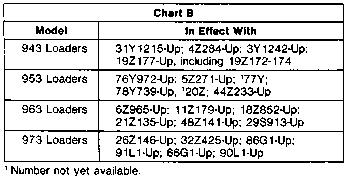
30 Page 30 of 75 Location of new parts in hydrostatic power case group. Transmission Filter Improved; Drain Line Added For Easier Service DESCRIPTION OF CHANGE: A drain lines group has been added to the power train arrangement for these machines. At the same time, the filter group for the hydrostatic transmission is changed for installation of the drain line and improved performance. NOTE: A later article that announced changes to the drain lines group has been included with this article. Some components of the drain lines groups have changed. The former drain lines groups had a plug at the outlet end of the drain hose. During machine operation, it was possible for a hole to be worn in the drain hose. This would cause the loss of transmission oil and cause a machine shutdown. The new drain lines groups have a valve that is mounted on the filter housing. This will keep transmission oil out of the drain hose until the valve is opened. There are two primary changes to the filter group. One is the addition of a hole at the front near the bottom of the housing for the drain line connection. The other change is removal of the support (rod) formerly used to hold the lower plate and the filter element to the cover assembly. A new cover assembly has only a short pin to hold the upper plate assembly and spring to the cover. The lower plate is now fastened to the bottom of the housing with a new bolt, washer and spring. A new plug in the bottom center hole of the housing has threads for this new bolt. The space around the lower plate will keep more of the dirt and sediment in the bottom of the housing, away from the clean oil. These changes will improve filter performance, and make filter service easier. ADAPTABLE AS: The new and former parts for the filter group are shown in Chart A and are in effect as shown in Chart B. The new and former parts for the drain lines groups are shown in Chart C.

31 Page 31 of 75
32 Page 32 of 75 MODIFICATION OF FILTER HOUSING: Earlier filter groups can be changed to the new design as follows: 1. Remove the complete filter from the machine as a unit. 2. Disassemble the filter. 3. Machine the new hole in the housing as shown in Illustration 1.
33 Page 33 of 75 Illustration 1. Dimensions to machine filter housing. 4. Remove the 3K6060 Nut, 3G1875 Plate, and the element from the support (rod) of the cover assembly. 5. Remove the 3B4617 Cotter, 4B4280 Washer, 3G1873 Plate Assembly, and 2J4045 Spring from the cover support (rod). Release the spring gradually, and be careful to prevent damage to the seal in the plate assembly. 6. Cut off the support (rod) of the cover assembly 12.7 mm (.50") below the hole for the cotter. Grind the end smooth, with a bevel to prevent damage to the seal in the plate assembly during installation. 7. Assemble the parts removed in Step Thoroughly clean all parts to remove any metal chips or particles. 9. Install a new 4T2638 Plug in place of the former 9S9334 Plug in the center hole in the bottom of the housing. 10. Put the 3G1875 Plate in position in the bottom of the filter housing. Assemble the 5M2894 Washer (first) and 4B7033 Spring on the 6V5804 Bolt, then install the bolt through the 3G1875 Plate and into the 4T2638 Plug. Tighten the bolt to a torque of 50 ± 7 N m (37 ± 5 lb ft). NOTE: Illustration 2 shows the locations of the new parts in the filter group. After the modification in Step 6, the former cover assembly is basically the same as the new cover assembly.
34 Page 34 of 75 Illustration 2. Filter group parts. 11. Install the Elbow, with the 3K360 Seal, in the new hole in the housing (Step 3). These are parts of the drain lines group. 12. Install the filter housing on the transmission and connect the 8G5494 Hose Assembly (drain line) to the Elbow. Also install the 5P2909 Plug in the other end of the hose assembly. 13. Install a new element, fill the filter with clean oil, and install the cover. NOTICE With this change in filter design, the 3G1875 Plate is not removed with the cover and element during normal filter service. For this reason, it will be necessary to check for any debris or foreign material on the plate, and clean it as needed at all future filter changes. The plug, if so equipped, must be removed from the hose and the oil drained before removal of the filter element. INSTALLATION PROCEDURE FOR 943 AND 953 LOADERS 1. Remove the existing drain hose and fittings from the transmission oil filter housing. See Illustration Install the 3K360 Seal and 6V7238 Valve (1) on filter housing. Be sure the outlet of the valve points down. 3. Install 160 cm (63") of 5P743 Hose (2) on valve (1). Use a 5D1026 Clamp (3) to fasten the hose to the valve.
35 Page 35 of Remove the lower front guard. Route drain hose (2) out to the lower front guard. 5. Use two 7K1181 Straps (4) to fasten drain hose (2) to the hydraulic tank drain hose as shown in Illustration 3. NOTE: Be sure there are no sags in hose (2) between Points A and B. 6. Install the center bottom guard and the lower front guard. Add oil to the transmission to replace that which was drained from the filter housing. Lower the cab. Illustration 3. Location of drain lines for transmission oil filter housing on 943 and 953 Loaders. INSTALLATION PROCEDURE FOR 963 LOADERS 1. Remove the existing drain hose and fittings from the transmission oil filter housing. See Illustration Install the 3K360 Seal and 6V7238 Valve (5) on the filter housing. Be sure the outlet of the valve points down. 3. Install 210 cm (82.7") of 5P743 Hose (8) on valve (5). Use a 5D1026 Clamp (9) to fasten the hose to the valve. 4. Route drain hose (8) to the rear access cover in the rear bottom guard. 5. Remove two bolts from the transmission oil pan at the locations shown. Install two 8J8197 Clips (7) on drain hose (8) and fasten the clips (7) to the transmission oil pan with bolts removed earlier. NOTE: Be sure there are no sags in hose (8) between Points A and B. 6. Install 8J8197 Clip (7) on drain hose (8). Remove a frame bolt in the area shown. Use the bolt to fasten clip (7) to the frame. 7. Install 7D7233 Clip (6) on the drain hose. Fasten clip (6) to the rear main frame crossmember with a 5P1075 Washer (11) and S509 Bolt (10). 8. Install the center bottom guards. Add oil to the transmission to replace that which was drained from the filter housing. Lower the cab.
36 Page 36 of 75 Illustration 4. Location of drain lines for transmission oil filter housing on 963 Loaders. INSTALLATION PROCEDURE FOR 973 LOADERS 1. Remove the existing drain hose and fittings from the transmission oil filter housing. See Illustration Install the 3K360 Seal and 6V7238 Valve (12) on the filter housing. Be sure the outlet of the valve points down. 3. Install 230 cm (90.6") of 5P743 Hose (13) on valve (12). Use a 5D1026 Clamp (17) to fasten the hose to the valve. 4. Route drain hose (13) to the rear access cover located in the rear bottom guard. 5. Remove two bolts from the transmission oil pan at the locations shown. Install 8J8197 Clip (14) with new Bolt (19). Install another 8J8197 Clip (14) with the bolt removed earlier. NOTE: Be sure there are no sags in hose (13) between Points A and B. 6. Install 8J8197 Clip (14) and 7D7233 Clip (18) on drain hose (13). Fasten clips (14) and (18) to the existing hole in the rear main frame crossmember with two 5P1075 Washers (16) and one S1594 Bolt (15). 7. Install the center bottom guards. Add oil to the transmission to replace that which was drained from the filter housing. Lower the cab.
37 Page 37 of 75 Illustration 5. Location of drain lines for transmission oil filter housing on 973 Loaders. Main Control Valve, Overspeed and Pilot Valve, Underspeed Valve Service Tips Make Sure All Parts Are Transferred From Used Transmission Control Valve To New Valve When A Replacement Is Made When a used 3G4502 Valve Group is replaced by a new 3G4502 Valve Group, it is very important that ALL serviceable parts from the used valve be transferred to the new valve. There are two small orifice plugs inside the 3G4502 Valve Group that are not part of the valve group. These two plugs are part of the transmission control group. See the illustration. The illustrations and parts lists for the transmission control group in the Parts Book should be used for reference when a replacement is made. If the 8J6815 Plug is not transferred from the used valve group to the new valve group, the machine brakes will be released as soon as the engine is started. This could permit unexpected movement of the machine.
38 Page 38 of 75 Location of 8J6815 and 9J8126 Plug in the 3G4502 Valve Group. Wear In Underspeed Guide Assembly Can Cause Engine To Lug Some machines may have a top speed that is as much as three seconds slow in 30 m (100 ft). There may also be problems in adjusting the full speed stops on these machines. The cause of these problems is a notch worn in the 3G8475 Guide Assembly in the underspeed (actuator) valve group. This notch is in the guide assembly where the rollers ride during normal operation. Examine the 3G8475 Guide Assembly on the side nearest the spring. If it has a notch near the top of the oval slot, order a new guide assembly. Underspeed valve group.
39 Page 39 of 75 Loader Will Not Move; Plugged Orifice In Main Control Valve Can Be Backflushed If the underspeed valve does not come up into position, the machine will not move. There can be several reasons for the underspeed valve not coming up into position. One reason is a plugged orifice in the system going to the operate/brake valve spool. It is possible to backflush the orifice (see the illustration) without disassembling the main control valve. First, use the procedure which follows to determine if a plugged orifice is the problem. Procedure To Check For Plugged Orifice NOTICE The U-TUBE, if so equipped, must be in the test position or the hose from the transmission to the brake manifold must be plugged on later machines. 1. With the centering bolt in the transmission lever, start the engine and bring it to high idle rpm. Pull the transmission lever to BRAKES OFF position and check the pressures at plugs (1) and (2). See Illustration 1. Illustration 1. Front view of transmission control valve. NOTE: On later loaders and all loaders that have been reworked, the shunt line to the left charge and relief valve will be connected at plug (1). Disconnect the line and remove the elbow to perform these tests. The pressure readings at both locations should be close to the charge pressure. If the pressure reading at plug (2) is close to charge pressure, a plugged orifice is NOT the problem. If the pressure reading at plug (2) is at or near zero and the pressure at plug (1) is close to charge pressure, then a plugged orifice is possibly the problem. Go to Step Put the transmission lever in the PARK position. Remove plug (3) and start the engine. If oil flows freely out of the opening, it is an indication that plug (4) is missing. If oil does not flow out the opening, go to Step 3.
40 Page 40 of Make sure the linkage to the pilot valve is connected. If the pressure reading at plug (2) remains at or near zero, after the above procedure has been performed, the problem is probably a plugged orifice. See Illustration 2. Use the procedure which follows to backflush the orifice. Illustration 2. Side view of transmission control valve. Procedure For Backflushing An Orifice 1. Install a hose between the charge pressure tap (quick disconnect) and plug (2). 2. Pull the transmission lever into the full forward position. This will keep the starting vent stem in a position that will allow the front side of the orifice to go directly to drain. 3. Start the engine and operate it at high idle rpm for a short period of time. Stop the engine. 4. Remove the back flushing hose and start the engine. Pull the transmission lever into the BRAKES OFF position. Check the pressures at plugs (1) and (2). Valve Stem Behind Underspeed Cut-In Adjustment Plunger Will Not Move Freely When adjusting the underspeed cut-in for hydrostatic transmissions, the light on the circuit tester may remain on even through the adjustment plunger is backed out and the engine is at the proper cut-in adjustment speed. This can be caused by an incorrectly adjusted cut-in indicator tool or from the 3G8706 or 4T2545 Stem not moving freely. The stem is located behind the underspeed cut-in adjustment plunger in the transmission control group. See the illustration. The stem does not move correctly for one of two reasons: (1) the adjustment plunger is turned in so far that the stem is forced into the bore, or (2) the hydraulic back pressure has been sufficient to force the stem into the bore. Either condition will cause the edge of the bore to deform, and the stem to be held in place. If this problem is encountered, inspect the stem to see if it moves freely.
41 Page 41 of Shut off the machine and remove the plug, lock, nut, plunger and seal as a unit. See the illustration. 2. If the stem is stuck in the bore, install a long screw with No threads in the tapped hole in the stem. Remove the stem. 3. Use a 9.35 ± 0.03 mm (.368 ±.001") diameter drill bit or reamer and a T-handle to clean up the bore. Apply a liberal amount of heavy grease to the flutes of the tool to hold the metal chips in the flutes. This will keep the chips out of the transmission. 4. Put a larger drill bit in the T-handle, coat the flutes with grease, and slightly chamfer the opening of the bore. Illustration 1. Transmission control group. 5. Install the parts as shown in the illustration, and use the adjustment procedure shown in the appropriate Service Manual. Illustration 2. View B-B of transmission control group.
42 Page 42 of 75 Major Improvements Installation Of Shunt Line And Removal Of Brake Check Valve Will Minimize Rollback Some machines have had a problem with movement after the center brake pedal has been depressed or after the transmission control lever has been moved to the PARK position. Also, some machines have experienced brief rollback motion just at the beginning of uphill movement. The installation of a shunt line after the removal of the brake check orifice valve will stop movement of the loaders after the brake has been applied or after the transmission lever is put in the PARK position. This will also minimize the rollback movement. This shunt line is factory installed on all later machines. See your Caterpillar Dealer for a list of the machines affected by this problem and for the new parts and installation procedure. New Tube Used Between Underspeed And Overspeed Valves (943, 953, 963 Loaders) A new tube and hardware are used in the hydrostatic power case lines groups on 943, 953 and 963 Loaders. The new tube connects the underspeed and overspeed valves. The new tube has been used on 973 Loaders since first production. In some applications, the former tube has failed at the connectors that are on the ends. If the tube fails, it can slow or stop the machine. See your Caterpillar dealer for a list of the machines affected by this change, a list of the new parts and the installation procedure. Location of new tube in hydrostatic power case lines group.
43 Page 43 of 75 Self-Locking Bolts Used In Underspeed Valve Group DESCRIPTION OF CHANGE: Self-locking bolts are now used to hold the valve group to the bracket in the underspeed valve groups in the hydrostatic transmissions. The self-locking bolts have deposits of nylon in the threads to keep the bolts tight. ADAPTABLE AS: The new 6V9665 Bolts are direct replacements for the former 2B2694 Bolts in this application. The new 6V9665 Bolts must be installed in place of the 2B2694 Bolts whenever the underspeed valve group is disassembled. The new bolts are to be tightened to a torque of 25 ± 5 N m (18 ± 4 lb ft). Location of new bolts in underspeed valve group. Drive System Does Not Operate Correctly; New Transmission Filter Relief Valve Spools DESCRIPTION OF CHANGE: Three new filter relief valve spools are available for use in the transmission control group. These valves are available in three different outside diameters. The new valves have a hole in them which is perpendicular to their length. They are also longer to make better alignment with bore in the valve group. These two changes will permit the valve to open more when oil is sent to drain but still have enough length for good alignment in the bore. The former valve spool was not available for parts service. With the former spool, it was possible for debris to hold the valve in the "open" position. It was also possible for the spool, because of it's shorter length, to get out of alignment with the bore. This caused the valve spool to stick (be held in place). Either or both of these two problems can result in the type of operation which follows. When transmission oil is cold, the relief valve is normally pushed open a small amount. In this position any foreign material on the pump side of the relief valve can be held in the narrow opening.
44 Page 44 of 75 As the transmission oil becomes warm, the loader will only move slowly with the governor control lever at high idle. But when the governor control is moved forward, toward low idle, the loader moves faster as the underspeed override valve is opened. ADAPTABLE AS: The new valve spools are adaptable to 943, 953, 963 and 973 Loaders. The new valve spools and their outside diameters are shown in the chart. The new spools can be installed as shown in the illustration. When a loader has this operation problem, it is our recommendation that all three new valve spools be used to find out which one has the best fit with the bore in the valve group. The largest diameter spool that fits correctly into the bore must be used. This new spool can then be used as a direct replacement for the former spool. Location of valve spool in transmission control valve group. Lock No Longer Used Under Nut On Adjustment Screw For Underspeed Cut-In The 3S4506 Lock is no longer used under the nut on the adjustment screw for the underspeed cut-in. The lock was part of the transmission control group. Because analysis has shown the lock is not necessary, the lock was removed to make assembly easier. Remove the 3S4506 Lock when the underspeed cut-in is adjusted.

45 Page 45 of 75 Location of the 3S4506 Lock. Standard Nut Used Instead Of Locknut To Hold Transmission Linkage Adjustment DESCRIPTION OF CHANGE: A standard type nut is now used instead of a locknut on the pilot valve rod end, and on the pilot valve linkage rod in the transmissions. Use of a standard nut in these applications makes assembly and adjustment of the linkage faster and easier. ADAPTABLE AS: Direct replacement. The new 1B4201 Nut can be installed in place of the former 2L9038 Locknut on all earlier machines, and the recommendation is to change the nut during any service work on these components. One nut is used on the 1U425 Rod End in the pilot valve group (overspeed), and one on the 3G8609 Rod in the hydrostatic power case linkage group. Location of nut in pilot valve group.
46 Page 46 of 75 Location of nut in linkage group. Servo Control Valves And Linkage Service Tips Adjustment Of The Neutral Screws For Servo Valves In Hydrostatic Transmissions Some servicemen have had problems trying to center the neutral screws for the servo valves in the hydrostatic transmissions. See the illustration. A correctly adjusted neutral screw may not be centered when the servo valves are correctly adjusted. The Service Manuals say to "center the neutral screw" during assembly, this is not correct. The neutral screw does not have to be centered. The neutral screws can be adjusted either hydraulically or with the air neutral procedure given in the appropriate Service Manual. But, they must be adjusted after the centering spring, the direction-speed link, the pilot valve link and the sync screws have been adjusted. If desired, on machines with the shunt line installed, the following procedure can be used to make quick, approximate adjustments of the neutral screws. Then, make the final adjustment by using the pressure test procedure given in the Service Manual. Use the Service Manual as a reference during the procedure. 1. Adjust the centering spring, the direction-speed link, the pilot valve link and the sync screws. This is done manually by inspection. See the illustration. 2. Close the synch shutoff valve. 3. With the transmission control lever held in PARK, start and run the engine at low idle. 4. Increase the engine speed in increments of 100 to 200 rpm as needed to hear the transmission noise. 5. Quickly adjust the neutral screws until the drive pressure decreases to zero and the transmission noise stops. 6. Continue increasing engine speed to high idle rpm.
47 Page 47 of Turn the neutral screw on each side clockwise until the noise is heard. Then, while counting the clicks, turn each neutral screw counterclockwise through the "no noise" range until noise is again heard. Turn the screws back clockwise one-half the counted number of clicks. The neutral screws are now temporarily adjusted. Use the pressure test procedure, given in the Service Manual, for the final adjustment. Location of components under the top cover. Correct Installation Of Oil Lines Between Servo Valves and Servo Cylinders If a hydrostatic transmission was disassembled and assembled for repairs, and the transmission is experiencing a high pressure on the left drive side that stops the engine shortly after it is started, it can be assumed that the oil lines between the left hand servo valve and left hand servo cylinder were not installed correctly. Remember, these oil lines are crossed. The oil lines on the right side run parallel. See the illustration. NOTE: Identification should be put on all lines before removing them. This will make sure that they are installed in their original locations. The engine will also be stopped or will stall to a lower speed if the neutral screws are out of adjustment by a very large amount. Correct location of oil lines between servo valves and servo cylinders.
48 Page 48 of 75 Air Neutral And Pressure Neutral Adjustments Will Not Stabilize If it is not possible to get a stabilized air neutral or pressure neutral adjustment when adjusting the neutral screw, there may be misalignment between the mechanical linkage plate and the servo valve bodies. This misalignment causes the servo valve sleeves to stick in the bodies. When installing servo valves, use the procedure which follows. Installation Procedure 1. Put the servo valves in position in the case. 2. Install the bolts that hold the servo valves to the manifold. Do not tighten the bolts at this time. 3. Install the sleeves in the servo valves. 4. Put the power control unit linkage in position on the servo valves. Use care when the servo valve stems are installed into the servo valve sleeves. Make sure the plate of the power control unit linkage sets flat on the top of the servo valves. Move the power control unit linkage and servo valves a small amount to put the servo valves, sleeves and stems all in alignment. Hand tighten the bolts. 5. Very carefully, remove the power control unit linkage from the servo valves. Tighten the two bolts that hold each servo valve in place to 45 ± 3 N m (33 ± 4 lb ft). 6. Install the power control unit linkage and make sure it installs freely over the top of the servo valves without any misalignment. Machine Does Not Operate Correctly; Control Linkage Ball Can Come Loose From Stud In some early machines, the rod ends in the internal hydrostatic transmission linkages were not staked correctly. This can permit the control linkage ball to come loose from the stud. The result of this is the machine will stop or one steering pedal will not work correctly. Your Caterpillar Dealer has a list of the machines affected by this and a procedure for correctly staking the internal linkage rods. Rod ends which were not staked correctly. Axial Piston Pumps, Case, Pump Drive Housing Service Tips
49 Page 49 of 75 Failure Of Bearings And/Or Input Gears In Hydrostatic Transmissions 953 Loaders Failures of the input gears and bearings in the hydrostatic power case groups and/or the rear bearings in the axial piston pump groups, may be caused by too little or no lubrication. Oil normally flows to the components through cross-drilled passages from core passages on each side of the transmission. It is possible that the cross-drilled passages do not intersect the core passages on some 953 Loaders. This stops the flow of oil to the gears and bearings. If burnt bearings and/or damaged input gears are found in a hydrostatic transmission, inspect the case to make sure that the cross-drilled passages intersect with the core passages, and that the orifices in the cross-drilled passages are open. If they do not intersect, drill a 6.35 mm (.25") diameter hole between the drill passage and core passage. Drill the opening at an angle behind the seal. See the illustration. Location of oil passage in transmission case. Oil Leakage Between Transmission Case Assembly And Pump Drive Housing At 5P4268 Seals 963, 973 Loaders The hydrostatic transmissions in some 963 and 973 Loaders have had oil leakage between the case assembly and the pump drive housing. This leakage is caused by pressure surges in the transmission charging system. The surges become amplified at the end of the core passages in the main case and leakage occurs through the 5P4268 Seals. See Illustration 1. The leakage is usually seen on the external surface of the transmission, or there may be a change in the oil levels as the oil transfers from the main case assembly to the pump drive housing.
50 Page 50 of 75 Illustration 1. Location of 5P4268 Seals in transmission case. Whenever a hydrostatic transmission head is removed from an early 963 or 973 Loader or if this problem occurs, the oil supply from the core passage in the head assembly (both sides) to the dead end passage in the main case assembly should be plugged off. This will stop the leakage problem. Use the procedure which follows to modify the head assembly. Modification Procedure for Head Assembly 1. Remove the head assembly from the hydrostatic power case group. NOTICE Do not drop the port plates from their dowels on the head.
51 Page 51 of 75 Illustration 2. Location of 9S8008 Plugs in head assembly. 2. Remove the 9S8008 Plug and the 3D2824 Seal from each end of the head assembly. See Illustration Drill a 6.2 mm (.244") diameter hole 15.0 mm (.59") deep in each side of the head assembly. See Illustration 3. Tap the holes with a 1/16"-27 NPTF tap. Thoroughly clean the head assembly at these locations. Install the 2S7905 Plugs at these locations. Use 5P3413 Pipe Sealant with Teflon on the threads of the plugs. NOTE: Either 5P9452 or Plugs can be used as replacements for the 2S7905 Plugs. 4. Install the head assembly, the 3D2824 Seals and the 9S8008 Plugs. See the Service Manual for assembly and start-up procedures. 5. Check the oil levels in the hydrostatic power case group. Operate the machine and check for leaks or changes in the oil levels in the main case assembly and pump drive housing. NOTICE Do not plug this passage on 943 or 953 Loaders. This will result in an immediate failure of the piston pump bearing on the gear input end of the pump shaft.
52 Page 52 of 75 Illustration 3. View A-A. Oil Transfer Out Of Hydrostatic Transmission Oil can transfer out of the piston pump compartment in the hydrostatic transmission into: 1) the flywheel housing, 2) the pump drive portion of the hydrostatic transmission, or 3) into the dry compartment between the final drive and the main frame where the parking brake group is mounted. If an oil transfer problem occurs in one of the three areas, the following checks should be made. 1. Oil transfer into the flywheel housing can be recognized by oil blowing out of the breather located at the top of the flywheel housing. This can be confirmed by removing the 8B8817 Plug from the bottom of the flywheel housing. This is normally a dry housing. This type of transfer can be direct from the piston pump compartment through a cut 5H7153 Seal (used in hydrostatic drive group), indirectly through the pump drive or through the hydrostatic drive group into the flywheel housing. When oil is observed blowing out of the flywheel housing breather, always check the oil levels in the pump drive and engine to confirm the transfer of oil. Use the procedure that follows to verify that the oil leakage is through the hydrostatic drive group and to correct the problem. a. Remove the 8B8817 Plug from the flywheel housing, and check for clear transmission oil in the housing. See Illustration 1. The housing normally is a dry compartment. b. If transmission oil is found in the housing, refer to the Service Manual, and remove the hydrostatic drive group.
53 Page 53 of 75 Illustration 1. Location of 8B8817 Plug in flywheel housing. c. Inspect the hub assembly to see if the plate has moved from the press fit location. See Illustration 2. If the plate has moved, proceed to Step d. If the plate appears to be in place, remove the 7P7727 Shaft and stand the hub assembly with its plate end down. Pour some diesel fuel into the hub, and watch for leakage around the 8G2777 Plate. If leakage occurs, pour the remainder of the fuel out of the hub and remove the plate. Proceed to Step d. If no leakage is found, check for transfer of oil through a cut seal or indirectly through the pump drive. d. Using a dial indicator, check the roundness of the bore in the hub. If the bore is round within mm (.0010") or less, proceed to Step f. If the bore is out of round by more than mm (.0010") proceed to Step e. e. Machine the minimum amount of material necessary to make the bore round within mm (.0010"). f. Measure the inside diameter of the bore. Measure the outer diameter of the 8G2777 Plate. If the bore measurement is more than mm (.0030") larger than the diameter of the plate, proceed to Step g. If the plate diameter is within mm (.0030") of the bore diameter, proceed to Step h.
54 Page 54 of 75 Illustration 2. Location of 8G2777 Plate in the hub assembly. g. Fabricate a new plate from low carbon steel to the dimensions given in Illustration 3. The diameter of the plate must be mm (.0030") larger than diameter of the bore. Proceed to Step i. Illustration 3. Dimensions for new plate. h. Using a knurling tool, knurl the outer edge of the 8G2777 Plate. i. Thoroughly clean the plate and the bore in the hub. Put a liberal coating of 9S3265 Retaining Compound in the bore. j. Install the plate in the hub assembly. Use a socket that is approximately the same diameter as the plate to force the plate in place. Under no circumstances should the plate be forced in with only a hammer.
55 Page 55 of 75 k. Stand the hub assembly with its plate end down. Pour some diesel fuel into the hub, and watch for leakage around the plate. - If leakage occurs, repeat the procedure starting at Step d. - If no leakage occurs, install the shaft in the hub assembly. l. Install the hydrostatic transmission. m. Start and operate the machine. 2. Oil transfer into the pump drive housing can be recognized by a greatly elevated oil level at that location and a lowering of the oil level in the sight gauge of the piston pump compartment. This is generally caused by one of the three 6V3382 Seals (used in the hydrostatic power case group) being installed at a slight angle or the sealing lip of the seal is cut. It is also possible that a 5P7031 Seal may have been installed in place of a 6V3382 Seal on the inner end of the 9J3061 Gear. NOTICE When 6V3382 Seals are installed, use a flat plate with a hole which will fit over the pump shafts. This will make sure that the seals are installed square with the housing. If a new seal lip running surface is needed, an installation washer no thicker than mm (.0625") can be used to reposition the seal shell below the machined surface of the housing. A seal which is installed out of square by 0.51 mm (.020") or more, will allow oil to be pumped under its sealing lip during normal shaft rotation. 3. Oil transfer into the dry compartment between the final drive and main frame can be recognized by a loss of oil from the piston pump compartment with no increase in oil level in any other compartment. This is caused by loose fittings in the parking brake lines group. The final drives must be removed to make this repair. Use the information which follows to check the dry compartment in the main frame. 943 and 953 Loaders: Loosen the 8G930 Spanner Nut in the parking brake group. If oil drains out, it can be assumed an internal oil leak exists. 963 and 973 Loaders: Remove the bolt from the main frame at the location shown in Illustration 4 or Illustration 5. If oil drains out of this location, it can be assumed an internal oil leak exists.
56 Page 56 of 75 Illustration 4. Main frame for 963 Loaders. Illustration 5. Main frame for 973 Loaders. Major Improvements Seal Added To Hub Assembly In Hydrostatic Drive Groups (963, 973 Loaders) DESCRIPTION OF CHANGE: A seal has been added to the hydrostatic drive group for 963 and 973 Loaders. The new seal fits between the existing seal of the same part number and the splines on the hub assembly. See the illustration. The extra seal will decrease oil leakage through the gear bore that is possible because of component tolerances. ADAPTABLE TO: The 5H7153 Seal can be added to all earlier 963 and 973 Loaders as shown in the illustration.
57 Page 57 of 75 Locations of the new and existing 5H7153 Seals in the hydrostatic drive groups. New Liquid Sealant Used Between Pump Drive And Hydrostatic Case Housings DESCRIPTION OF CHANGE: A new sealant is used between the pump drive housing and the hydrostatic case housing. The new sealant will remain a liquid until the pump drive housing and the hydrostatic case housing are connected, and the bolts are tightened. Extra sealant will dissolve in oil. The sealant can be removed easily with a putty knife or scrub pad during later disassembly work. New sealant can then be used during assembly. ADAPTABLE AS: The new 6V6640 Sealant is a direct replacement for the former 7M7260 Sealant used at this joint. Apply the sealant to only one of the faces that are connected. NOTE: The surfaces that are to be sealed must be slightly rough to retain the sealant when the pump drive housing is bolted to the case housing. The finish on the surfaces should be approximately 2.9 to 3.8 micrometers (116 to 152 microinches). If the surfaces are too smooth they can be made rougher with a fine file. Do not use a caustic or phosphate cleaning solution on the surfaces. New Axial Piston Pump Groups Have Better Lubrication Between Piston Assemblies And Barrel Assembly (953, 963, And 973 Loaders) DESCRIPTION OF CHANGE: New axial piston pumps groups are used in 953, 963 and 973 Loader transmissions. These new pump groups have new piston assemblies with a smaller diameter. This smaller diameter gives better lubrication between the piston assemblies and the barrel assembly. ADAPTABLE AS: The new pump groups are direct replacements for the former pump groups as shown in the chart. The new piston assemblies can be used with the former piston assemblies in the same pump group.
58 Page 58 of 75 Rotate Input Shafts During Installation Of Pump Head On Hydrostatic Transmissions During installation of the pump head on the hydrostatic transmission case, it is very important to rotate (turn) the pump input shafts as the head bolts are tightened. The pump input shafts, bearings, and barrels can drop out of alignment a small amount when the head is removed. During installation of the head, rotation of the input shafts will bring the bearings into correct alignment in the head. Damage to internal components is possible if this procedure is not followed. If the head on the hydrostatic transmission has been assembled correctly, the serviceman will be able to turn the main input shaft with a 61 cm (2 ft) extension bar or pipe wrench. New Spring Used In Axial Piston Pumps 943 Loaders DESCRIPTION OF CHANGE: A new spring is used in the axial piston pump on 943 Loaders. The new spring is longer and will permit pump assembly with only two spacers. The former spring needed three spacers to get the correct assembled load. ADAPTABLE AS: The new 4T360 Spring and two 8J482 Spacers are a direct replacement for the former 3G6488 Spring and three 8J482 Spacers. The new spring has a yellow stripe and is mm (3.580") long. Three spacers must still be used in pumps that have the former spring. Location of the spring and spacers. Charge And Main Relief Valve, Sync Valve, Oil Cooler
59 Page 59 of 75 Service Tips Overheating Of The Hydrostatic Transmission Anytime overheating of the hydrostatic transmission occurs, check the transmission oil cooler core for external restrictions or plugging. To do this, move a shop light to all areas behind the core and inspect around the tubes for restricted and plugged areas. The area around the tubes may not be totally plugged, but enough debris may be wrapped around the tubes to provide sufficient restriction to cause overheating. If restricted or plugged areas are found, clean the core with high pressure steam and soap. High pressure water or air alone will not clean the core, steam and soap must be used. The fin spacing and tube spacing are closer on transmission cooler cores than on engine radiators. For this reason, more careful methods of cleaning are required on transmission cooler cores. NOTE: On 953, 963 and 973 Loaders, the hydraulic oil cooler must be folded down to allow complete cleaning of the transmission cooler core. In some cases it may be necessary to remove the oil cooler and have the cooler cleaned at a repair shop. Use Only Forged Elbows In Line Between Sync Valve And Sync Shut-Off Valve The Elbows were originally made either as a fabrication (and the parts brazed together) or as a forging. The fabricated elbows can be identified by their gold color. The forged elbows can be identified by their silver color. Now, only forged elbows are made. The brazed (gold colored) Elbows have separated in some hydrostatic transmission applications. Because of this, use only the forged (silver colored) Elbows in the hydrostatic power case lines group. Any brazed elbows should be used in other applications. Quick Response And Filter Relief Valves Can Be Easily Removed For Service The Disassembly And Assembly Sections of the Service Manuals for these loaders, show how to remove the main control valve. In the disassembly of the main control valve they show how to remove the quick response and filter relief valves from the control valve. The Service Manuals show the removal of the control valve and its manifold as a unit. If service work is to be done on only the quick response or filter relief valves, the manifold does not have to be removed. This will make it possible to leave the top cover of the power control unit and the pilot valve in position and eliminate the need to readjust the top linkage after the control valve is installed. To remove the main control valve and still leave the manifold in position, use the following procedure: 1. Remove the oil filter housing. 2. Remove the oil lines shown in the illustration and disconnect the oil lines on the other side of the control valve (not shown). 3. Fasten a hoist to the control valve. 4. Remove the five bolts on the side of the main control valve that hold the valve to the manifold and power control unit. (On some models it may be necessary to remove the charge pump.) 5. Remove the seven bolts that hold the control valve to the manifold.

60 Page 60 of Remove the control valve. Location of the parts that must be removed. Major Improvements New Spacer Used In Assembly Of Screens On Oil Cooler Return Tube In Transmissions 943, 953, 963 Loaders DESCRIPTION OF CHANGE: A new spacer is used on the bolt that holds the three screens on the oil cooler return tube in the hydrostatic power case lines groups. The design of the new spacer permits better control of tolerances, especially spacer length. This will make sure the screens are held in place with the correct amount of force when the bolt is tightened. Formerly, it was possible for differences in spacer length to cause either too much or too little force to hold the screens correctly in place. ADAPTABLE AS: The new 4T5919 Spacer is a direct replacement for the former 3H3244 Spacer, and can be installed in the hydrostatic power case lines groups on all earlier 943, 953 and 963 Loaders. Plugs Removed From Charge And Main Relief Valves For Hydrostatic Transmissions DESCRIPTION OF CHANGE: A change has been made to the charge and main relief valves in hydrostatic transmissions. The valve bodies used in these valve groups have been changed to remove several holes which are not needed, and the plugs and seals for these holes are now removed from the valve groups as shown in the illustrations. This will prevent the possible development of leaks around the plugs. The holes in which the plugs were installed were used for special tests, and are not necessary for normal tests or for troubleshooting. ADAPTABLE AS: Direct replacement. The part numbers of the 3G5008 (RH), 9J365 (LH), and 9J8554 (RH) Valve Groups are not changed. Three 9S4191 Plugs and three 3J1907 Seals are removed from the 3G5008 Group, and four 9S4191 Plugs and four 3J1907 Seals are removed from the 9J365 and 9J8554 Groups. The illustrations show the locations of the plugs and seals in earlier valve groups. Later groups have no holes for these parts.
61 Page 61 of 75 Locations of plugs and seals in earlier 3G5008 Valve Groups (RH). Locations of plugs and seals in earlier 9J8554 Valve Groups (RH). The 9J365 Valve Groups (LH) use the same basic valve group and valve body, so hole locations are the same for both groups. Hardened Washers And New Bolts Used To Prevent Loss Of Bolt Torque DESCRIPTION OF CHANGE: Hardened washers and new bolts are used in the hydrostatic power case group to hold the charge and main relief valve groups in place, on the above machines. With the washer, the force caused by the torque on the bolts pushes against a larger surface area and will hold that torque better. Formerly, washers were not used under the bolt heads. It was possible for the bolt heads to cause distortion of the valve body during high pressure conditions. The result of this was a possible loss of bolt torque and leakage past the seals between the valves and the hydrostatic transmission head.
62 Page 62 of 75 Because of the thickness of the washers it was necessary to use longer bolts in some of the locations. The new bolts are 6.35 mm (.25") longer than the original bolts. ADAPTABLE TO: The washers and new bolts are adaptable to all 943, 953, 963 and 973 Loaders. The torque specification for these bolts did not change. Location of bolts and washers. Teflon Ring in Transmission Charge and Main Relief Valve Groups Can Be Cut For Easier Installation There have been changes made to some components in the charge and main relief valve groups in the hydrostatic transmissions. The 9J8136 Seats were replaced by the 1U4833 Seats and the Rings were replaced with Rings in the sync valve. See the illustration. The new Ring can be either a split Teflon ring or a solid one. Installation of the solid ring can be difficult. The ring must be stretched and twisted during installation. This can damage the ring. Our recommendation is to use a sharp knife and cut the solid Teflon ring at 45 to 60 angle for easier installation. No modification is necessary if the Ring is already split.
63 Page 63 of 75 Location of Teflon rings in sync valves. Brakes And Motors Service Tips Use A Brake Release Pump When Towing Track-Type Loaders The brakes must be released when hydrostatic loaders are towed. Former loaders had an on-board hand pump which released the machine brakes. New loaders need an external (outside) power source. You can fabricate a portable pump group that is hand powered. The FT1845 Pump Group has a 7H1680 Volume Compressor (Pump) with a gauge, hoses, valves, and fittings. These components are necessary to control the oil pressure and connect the pump to the brake circuit. Follow this procedure to make the pump group: 1. Remove the original hose and fittings from the pump. 2. Use the instructions printed on the side of the pump reservoir to adjust the pump handle linkage to kpa (2500 psi) position (maximum volume per stroke).
64 Page 64 of 75 Illustration 1. FT1845 Pump Group. 3. Add the hose and fittings to the pump cover. See Illustration 1 for correct assembly and parts identification. 4. Fill the reservoir with SAE 10W oil.
65 Page 65 of Before you use the pump group to release the loader brakes, adjust the 8T477 Relief Valve on the pump group: a. Close the manual valve (Item 3 in Illustration 1) and plug the end of the hose with a 5P2909 Plug. NOTE: Install a Elbow (1/2" - 14 NPT street elbow) in the relief valve port on the side of the 8T477 Relief Valve. This street elbow is not part of the FT1845 Brake Release Group. Make sure the elbow is directed toward the pump reservoir. Remove the cover of the pump to allow oil flow from the relief valve port to fall into the pump reservoir while the relief valve is set. b. Adjust the relief valve so it starts to drip oil at approximately 1380 kpa (200 psi) while slowly pumping. c. The pressure reading at the gauge will increase as you pump faster to increase the rate of oil flow through the relief valve. While you operate the pump handle at the rate of one stroke per second, adjust the relief valve again, if necessary, so the maximum pressure reading is between 1900 kpa (275 psi) and 2075 kpa (300 psi) with all the pumped oil flowing through the relief valve. This will protect the tractor brakes from excessive pressure surges. d. After adjusting the relief valve, open the manual valve to return the pressure to zero. Remove the 5P2909 Plug from the hose. Install the cover on the pump reservoir. 6. You must connect the service pump hose to the 8M505 Fitting at the inboard side of the 3W305 Manifold. The manifold is at the rear of the left ROPS support. a. Disconnect the hose which comes from the transmission and plug it with the 5P2909 Plug. See Illustration 2. b. Connect the service pump hose to the 8M505 Fitting. This is the fitting from which the hose was removed. 7. Block the machine to prevent movement. When the brakes are released, the machine is free to move. This could cause personal injury or property damage. Block the machine to prevent movement until it is ready to tow.
.")
66 Page 66 of 75 Illustration 2. Pump connection to manifold. 8. Close the manual valve. Pump the oil until it reaches a pressure of 1025 to 1375 kpa (150 to 200 psi). This will fully release the brakes. You can maintain this pressure by an occasional stroke on the pump handle on a brake system that is in good working condition. The pressure must not reach more than 2075 kpa (300 psi). NOTICE Brakes must be fully disengaged when the loader is towed. If they are partially engaged, they will overheat and damage will result. Keep the pressure between 1025 and 1375 kpa (150 and 200 psi) to be sure brakes stay disengaged. Pressures that go higher than 2075 kpa (300 psi) can damage the components of the brake system. Personnel operating the service tool while riding on the towed machine should keep the seat belt fastened to prevent possible injury when the machine suddenly stops. 9. If the brakes must be used, turn the valve (Item 3 in Illustration 1) 90 to the open position. The pressure of the circuit will drop to zero and the brakes will work immediately. The machine will stop suddenly. 10. To apply the brakes after the machine is towed, turn the manual valve handle 90 to the open position.
67 Page 67 of 75 False Leakage Indications Possible During Instrument Tests On Hydrostatic Transmissions False indications of excessive (too much) leakage are possible during instrument tests on the hydrostatic transmissions used in some track-type loaders. The Service Manual instructions for the "Instrument Tests" tell you to "change the location of the U-TUBE on the brake instruction panel from RUN to TEST," during preparation of the machine. See the illustration. When the U-TUBE is in the TEST position, oil under pressure from the transmission is sent to the hand pump. If there is leakage past the check valves in the hand pump, the oil will flow into the sump of the transmission. This leakage into the sump will cause a) low charge pressure indications and/or b) low cooler flow indications during the instrument tests. If low charge pressure indications and/or low cooler flow indications are present, move the U- TUBE to the TOW position and install the cap tightly on the open port. Do the instrument test again to find if the leakage is in the hydrostatic transmission or in the hand pump. If the leakage was in the hand pump, the charge pressure and cooler flow indications will now be normal. Location of the U-TUBE and the brake instruction panel. Major Improvements Plunger Assembly Replaces Adjustment Screw In The Speed Override And Brake Control Pedal The 3W3321 Plunger Assembly replaces the 4B3615 Adjustment Screw. The 1D5117 Nut is still used with the new plunger assembly. This plunger assembly does not affect the operation of the speed override and brake control pedal. When the pedal is pushed down until the spring in the plunger assembly is felt, the transmission pumps will be close to zero angle and the
68 Page 68 of 75 brakes will still be released. When the pedal is pushed past the spring to the stop, the brakes will be applied. The 3W3321 Plunger Assembly is in effect as shown in the chart. Adjustment Procedure For Plunger Assembly 1. Turn the plunger assembly until it is even (flush) with the bottom of the pedal. 2. Use the procedures given in the appropriate Service Manual to adjust the speed override and brake control group. 3. For adjustment of the plunger assembly, hold the pedal down until the lever makes contact with the stop on the brake valve housing. With the pedal in this position, turn the plunger assembly in until the plunger contacts the pedal support housing. 4. Release the pedal. 5. Turn the plunger assembly clockwise, four additional turns. Tighten the 1D5117 Nut to 45 ± 7 N m (33 ± 5 lb ft). Location of speed override and brake control components. To check the adjustment of the plunger assembly, install a pressure gauge in the brake pressure tap on the top of the transmission control valve. Start the engine and bring it to high idle rpm. Put the transmission control lever in the BRAKES OFF position. The brake pressure will show on the gauge. Push the center pedal down until the plunger just makes contact with the pedal support. The gauge reading should remain the same. Push the pedal all the way down and the pressure should go to zero. New Joint Assembly Used In Piston Motor 943 And 953 Loaders DESCRIPTION OF CHANGE: A new joint assembly is used in the piston motor group on 943 and 953 Loaders. The new joint assembly is stronger and will have a longer service life.

69 Page 69 of 75 ADAPTABLE AS: The new 4T8689 Joint Assembly is a direct replacement for the former 4T1693 Joint Assembly which is canceled. Use Thread Sealant To Prevent Oil Leakage Around Stop Bolts In Track Motor Groups 973 Loaders Location of 3G9710 Bolt in 3G5014 Track Motor Group. There have been reports of oil leakage around the 3G9710 Stop Bolts in the 3G5014 Track Motor Group on 973 Loaders. See the illustration. The leakage can be prevented with thread sealant. If a machine has this problem, make an alignment mark on the head of the bolt and on the case. Count the number of turns needed to remove the bolt. Put 7M7260 Liquid Gasket on the bolt. Install the bolt back into the motor group case with the same number of turns. The bolt will then be in its original position. NOTE: If bolt is not returned to its original position, the motor angle will be changed and can cause machine to drift right or left during operation. If the track motor group is disassembled for any reason, be sure to put liquid gasket on the threads of the stop bolts. New Shaft And Retainer Available For Field Installation In Piston Motors 943, 953, 963 Loaders DESCRIPTION OF CHANGE: A new shaft and retainer, with a different snap ring and a pin, are available for field installation in piston type hydraulic motors used on the above models. The new parts are used for replacement of the former retainer and snap ring to hold the barrel spring in existing hydraulic motors, and have a new stronger design for longer service life. On some machines, failure of the former snap ring and/or retainer has caused too much case drain leakage and loss of torque from the motor.
70 Page 70 of 75 ADAPTABLE TO: The new parts shown in Chart A can be installed in the piston motor groups shown in Chart B on existing machines. This conversion permits removal of the former 9J8052 Retainer and 8J6274 Snap Ring. The new parts must be used together for conversion of each motor. New Universal Joint Used In Piston Motor Group 963 And 973 Loaders DESCRIPTION OF CHANGE: A new universal joint assembly is used in the piston motor group on 963 and 973 Loaders. The new universal joint assembly has a stronger input yoke. The new yoke will give a longer service life. ADAPTABLE TO: The new 4T7480 Universal Joint Assembly is a direct replacement for the former 4T905 Universal Joint Assembly. See the illustration for the location of the new universal joint assembly. Location of universal joint assembly in piston motor group.

71 Page 71 of 75 New Sleeve In Hydrostatic Piston Link Motor Group Has More Resistance To Wear 973 Loaders DESCRIPTION OF CHANGE: A new sleeve is now used in the hydrostatic piston motor group on 973 Loaders. The new sleeve is made of a harder bronze material. Because of the new material, the new sleeve has more resistance to wear. ADAPTABLE AS: The new 4T2060 Sleeve is a direct replacement for the former 3G9706 Sleeve, which is canceled. Location of 4T2060 Sleeve in the motor group. General Service Tips Checking Right Drive Pressure On Hydrostatic Transmissions 973 Loaders Reports have been received concerning the difficulty in checking the right drive pressure on hydrostatic transmissions in 973 Loaders. When servicemen attempt to use a 6V4144 Coupling with the high pressure test hose, they find the fitting cannot be installed on quick disconnect couplings on the hydrostatic transmission. The coupling to adapter to elbow combination is too long and, thus, interferes with the tank. When checking the right drive pressure, use a 6V4143 Coupler connected directly to a 3B6552 Elbow. The elbow, in turn, is connected directly to the high pressure test hose. These parts can be easily installed on the quick disconnect coupling on the sync valve to read right drive pressure. Procedure To Tilt Operator Platform On Machines Without A Cab Some dealers have desired information about the correct procedure to use when the operator platform must be tilted forward on loaders which are not equipped with a cab. Because of the
72 Page 72 of 75 different weight balance without a cab, the platform on these machines can not be tilted a full 90 with a single hoist. Use the procedure that follows: 1. Use the shop hoist to tilt the platform as far as possible. 2. Fasten a 5P9694 Ratchet Hoist between the lift hole on the back of the bucket, and the rear of the platform at the location of the opening for the instrument panel. 3. Use the ratchet hoist to pull the platform forward until the 8G148 Safety Brace Group can be installed. 4. To lower the platform, use the reverse procedure. Do not use the 5P9694 Ratchet Hoist to lower the platform beyond the position where it was lifted by the shop hoist. Use the shop hoist to lower the platform beyond this position. Case Drain Pressure Measurements When troubleshooting hydrostatic transmission problems, be sure to look at the test gauges carefully when starting the machine. If there is a total failure in one of the motors, the pressure could "peg" the gauge needle (move the gauge needle around to the stop) when the engine is started. The serviceman that is troubleshooting the transmission might read the gauge pressure as zero pressure. This will make troubleshooting difficult and will increase the time needed to make repairs. Correct Assembly Of Connectors In Hydrostatic Transmission There have been problems of separation of some tubes and connector assemblies in the hydrostatic transmission for 943 and 953 Loaders. This separation will give a loss in oil flow. Wrong assembly of the connector assembly can cause this separation. The parts of the connector assembly must be assembled in exactly the same position and sequence as shown in the illustration. For example, the anchor, which is similar to a bevel washer, must be installed with the small diameter toward the end of tube as shown. If the anchor is installed in the wrong position it can permit a separation of the tube from the connector assembly.

73 Page 73 of 75 Correct position of connector assembly parts. Major Improvements New Nut Assembly For Fittings In Hydrostatic Transmission A new 5P8752 Nut Assembly is now available for parts service. This new nut assembly is used on several different fittings in the hydrostatic transmission. The nut assembly permits the replacement of the nut, retainer, anchor, guide and seal in these fittings. Before, the complete fitting had to be ordered if one of these components was damaged. The 5P8752 Nut Assembly can be used for service of the 5P8547 Tee, 5P8548 Connector, 5P8549 Connector or 5P9036 Elbow. Nut Assembly Now Available For Parts Service DESCRIPTION OF CHANGE: The nut assembly that is used on the 5P8750 Connector and the 5P8546 Elbow in the hydrostatic power case lines group is now available for parts service. Formerly, this nut assembly was not available for parts service. If the nut assembly was damaged, it was necessary to make a replacement of the complete connector or elbow. ADAPTABLE AS: The new 5P8751 Nut Assembly is adaptable to all 5P8750 Connectors and 5P8546 Elbows.
RELEASING PRESSURE IN THE HYDRAULIC SYSTEM,
 Testing And Adjusting Introduction NOTE: For Specifications with illustrations, make reference to SPECIFICATIONS for 225 EXCAVATOR HYDRAULIC SYSTEM, Form No. SENR7734. If the Specifications are not the
Implement and Steering/Hydraulic System Testing and Adjusting
 Page 1 of 64 Testing And Adjusting Introduction Reference: This supplement contains the Specifications, Systems Operation, and Testing And Adjusting for the components and systems that are different than
Troubleshooting The Transmission Hydraulic System
 416B, 426B, 428B, 436B, & 438B BACKHOE LOADERS TRANSMISSION Testing And Adjusting Troubleshooting The Transmission Hydraulic System Make reference to the following warning and pressure tap locations for
Media Number -SENR Publication Date -01/10/1977 Date Updated -12/10/2001
 - - 55, 56, 57, 58 & 59 TOWING WINCHES Page 1 of 21 Testing and Adjusting 55, 56, 57, 58 & 59 TOWING WINCHES Media Number -SENR7217-01 Publication Date -01/10/1977 Date Updated -12/10/2001 Testing And
Introduction. General Information. Systems Operation
 Systems Operation Introduction Reference: For illustrated Specifications, refer to the Specifications For 416, 426, 428, 436, 438, & Series II Backhoe Loaders Transmission, Form No. SENR3131. If the specifications
Troubleshooting the Transmission Hydraulic System
 Testing and Adjusting IT28F INTEGRATED TOOLCARRIER POWER TRAIN Testing And Adjusting Introduction Reference: For Specifications with illustrations, refer to SENR5974, IT28F Integrated Toolcarrier Power
Hydrostatic Drive. 1. Main Pump. Hydrostatic Drive
 Hydrostatic Drive The Hydrostatic drive is used to drive a hydraulic motor at variable speed. A bi-directional, variable displacement pump controls the direction and speed of the hydraulic motor. This
Torque Converter, Transmission Pump, Screen And Filter
 Page 13 of 27 Transmission Hydraulic System In Forward (Engine Running - Type 2 & 3 Control Valve Shown) (4) Transmission control valve. (5) Neutralizer valve. (6) Neutralizer solenoid. (7) Flow control
k. Components not properly adjusted. Refer to machine technical manual for proper adjustment of components.
 General Troubleshooting Charts General Troubleshooting Charts Use the charts on the following pages to help in listing all the possible causes of trouble when you begin diagnosing and testing of a machine.
Track Drive Circuit - General System. Simplified Travel Circuit Diagrams: Neutral Controls Forward Travel Reverse Travel
 Section 7.1 Track Drive Circuit - General System Simplified Travel Circuit Diagrams: Neutral Controls... 7.1.2 Forward Travel... 7.1.4 Reverse Travel... 7.1.5 General... 7.1.3 Track Drive Circuit: General...
Hydrostatic System - Test and Adjust
 Testing and Adjusting 236B, 246B, 252B and 262B Skid Steer Loaders Hydraulic System Media Number -RENR4867-03 Publication Date -01/11/2009 Date Updated -24/11/2009 Hydrostatic System - Test and Adjust
Section 7.1. Wheel Drive Circuit - General System
 Section 7.1 Wheel Drive Circuit - General System Simplified Travel Circuit Diagrams: Neutral Controls... 7.1.2 Forward Travel... 7.1.4 Reverse Travel... 7.1.5 General... 7.1.3 Wheel Drive Circuit: General...
980 B Wheel Loader S/n 89P1 & Up Volume 1 of 2
 Caterpillar Service Manual 980 B Wheel Loader S/n 89P1 & Up Volume 1 of 2 Service Manual THIS IS A MANUAL PRODUCED BY JENSALES INC. WITHOUT THE AUTHORIZATION OF CATERPILLAR OR IT S SUCCESSORS. CATERPILLAR
Pilot Oil Supply Circuit
 Pilot Oil Supply Circuit Introduction Pilot system oil output from pilot pump (42) has the following three main functions: 1. To control main pump output. 2. To provide easier operation of control levers.
AUTOMATIC TRANSMISSIONS Mitsubishi F3A20 Series TRANSMISSION APPLICATION TABLE
 Article Text ARTICLE BEGINNING AUTOMATIC TRANSMISSIONS Mitsubishi F3A20 Series APPLICATION TRANSMISSION APPLICATION TABLE Vehicle Application Transmission Model Colt 3-Speed (1990-94)... F3A21 Colt Vista
WEBER CARBURETOR TROUBLESHOOTING GUIDE
 This guide is to help pinpoint problems by diagnosing engine symptoms associated with specific vehicle operating conditions. The chart will guide you step by step to help correct these problems. For successful
OPERATION AND PARTS MANUAL
 OPERATION AND PARTS MANUAL MODEL NUMBER : PART NUMBER : TAP- IN KIT 5100-5151 BAYNE MACHINE WORKS, INC. PHONE: (864) 288-3877 910 FORK SHOALS ROAD TOLL FREE: (800) 535-2671 GREENVILLE S.C., 29605 FAX:
Section 10 Chapter 17
 Section 10 Chapter 17 24 Valve, 8.3 Liter Engine Air Intake System Note: All coding used in the 8.3 Liter and 9 Liter engine manuals are Cummins engine codes. These engine codes have no meaning to New
Section 35 Chapter 2 HYDRAULIC SYSTEM HOW IT WORKS AND TROUBLESHOOTING NH
 Section 35 Chapter HYDRAULIC SYSTEM HOW IT WORKS AND TROUBLESHOOTING 6-80NH TABLE OF CONTENTS GENERAL INTRODUCTION... 35-3 Hydraulic Pumps... 35-3 Standard Flow PFC Pump Layout... 35-5 MegaFlow PFC Pump
STEERING HYDRAULICS The steering system is a flow amplified, load sensing, hydraulics arrangement.
 STEERING HYDRAULICS 116821 The steering system is a flow amplified, load sensing, hydraulics arrangement. When the steering wheel is turned, the Steering Metering Pump meters an oil volume proportional
D3 Crawler S/n 6N1 & 79U1 & up Volume 1 of 2
 Caterpillar Service Manual D3 Crawler S/n 6N1 & 79U1 & up Volume 1 of 2 Service Manual THIS IS A MANUAL PRODUCED BY JENSALES INC. WITHOUT THE AUTHORIZATION OF CATERPILLAR OR IT S SUCCESSORS. CATERPILLAR
Power Train. Chapter 5
 Chapter Power Train Spefications................................................................. -3 Test Spefications........................................................ -3 Repair Spefications.......................................................
Lesson 5: Directional Control Valves
 : Directional Control Valves Basic Hydraulic Systems Hydraulic Fluids Hydraulic Tank Hydraulic Pumps and Motors Pressure Control Valves Directional Control Valves Flow Control Valves Cylinders : Directional
Tests & Adjustments - General Machine. General Safety Hydraulic Tank Turbo Boost Regulator
 Section 8.1 Tests & Adjustments - General Machine General Safety......................................... 8.1.2 Hydraulic Tank Turbo Boost Regulator........................ 8.1.2 Hydraulic Tank Safety
4.2 WATER PUMP (GEAR CASE MOUNTED AND LATER) (GCM)
 (GCM)") SERIES 60 SERVICE MANUAL 4.2 WATER PUMP (GEAR CASE MOUNTED - 1991 AND LATER) (GCM) The centrifugal-type water pump circulates the engine coolant through the cooling system. The pump is mounted on the rear
SERIES 60 SERVICE MANUAL 4.2 WATER PUMP (GEAR CASE MOUNTED - 1991 AND LATER) (GCM) The centrifugal-type water pump circulates the engine coolant through the cooling system. The pump is mounted on the rear
Section 6.1. Implement Circuit - General System. General: TF Configuration TB Configurations Implement Control Valve:
 Section 6.1 Implement Circuit - General System General: TF Configuration... 6.1.3 TB Configurations... 6.1.5 Implement Pump Breakdown... 6.1.6 Operational Description: General... 6.1.7 Compensator Control...
Hydrostatic Power Train
 Chapter Hydrostatic Power Train Specifications................................................................. -3 Test Specifications........................................................ -3 Repair
Section 6.1. Implement Circuit - General System. General: TF Configuration TB Configurations Implement Control Valve:
 Section 6.1 Implement Circuit - General System General: TF Configuration... 6.1.3 TB Configurations... 6.1.5 Implement Pump Breakdown... 6.1.6 Operational Description: General... 6.1.7 Compensator Control...
Purging Air From Divider Block Lubrication Systems
 FROST ENGINEERING SERVICE Purging Air From Lubrication Systems A D I V I S I O N O F G E C S E Y S A L E S & S E R V I C E DESCRIPTION Divider block lubrication systems operate correctly only when all
HYDRAULICS. TX420 & & lower. Hydraulic Tandem Pump Removal. 4. Remove the LH side panel (Fig. 0388).
.") TX420 & 425 240000299 & lower 4. Remove the LH side panel (Fig. 0388). Hydraulic Tandem Pump Removal Note: Cleanliness is a key factor in a successful repair of any hydraulic system. Thoroughly clean all
TX420 & 425 240000299 & lower 4. Remove the LH side panel (Fig. 0388). Hydraulic Tandem Pump Removal Note: Cleanliness is a key factor in a successful repair of any hydraulic system. Thoroughly clean all
Ideal Installation. I & M Mark 67 (1/2 6 ) Control Line. Installation & Maintenance Instructions for Mark 67 Pressure Regulators
 Control Line. Installation & Maintenance Instructions for Mark 67 Pressure Regulators") I & M Mark (/ ) 0 Wasson Road Cincinnati, OH 0 USA Phone --00 Fax -8-00 info@richardsind.com www.jordanvalve.com Installation & Maintenance Instructions for Mark Pressure Regulators Warning: Jordan Valve
I & M Mark (/ ) 0 Wasson Road Cincinnati, OH 0 USA Phone --00 Fax -8-00 info@richardsind.com www.jordanvalve.com Installation & Maintenance Instructions for Mark Pressure Regulators Warning: Jordan Valve
BDU-10/21 Hydrostatic Transmissions Service and Repair Manual
 Hydrostatic Transmissions Service and Repair Manual BLN-50327 January 2018 Table of Contents Table of Contents Description Page Introduction... 3 General Description... 3-5 Fluids... 6 Safety Precautions...
Removal and Installation of Fuel Injection Pumps
 Page 16 of 126 worn considerably. Fig. C shows how the flat end of a new plunger makes poor contact with a worn lifter, resulting in rapid wear to both parts. An injection pump can have a good fuel flow
TRANSMISSION PARTS Instructions. Solenoid Regulator Valve Retainer Shim. Main Pressure Regulator Valve
 TRANSMISSION PARTS Instructions Sure Cure Kit Part No. SC-AODE NOTE: This kit is fully compatible with '91 '95 only. Identified by alignment pins 13mm heads. This kit will not work on '96 Later units.
I & M Mark 78 Series. Ideal Installation. Start-Up. Installation & Maintenance Instructions for Mark 78 Control Valves (1-1/2-2 )
") I & M Mark 8 Series 0 Wasson Road Cincinnati, OH 4509 USA Phone 5-5-5600 Fax 5-8-005 info@richardsind.com www.jordanvalve.com Installation & Maintenance Instructions for Mark 8 Control Valves (-/ - ) Warning:
I & M Mark 8 Series 0 Wasson Road Cincinnati, OH 4509 USA Phone 5-5-5600 Fax 5-8-005 info@richardsind.com www.jordanvalve.com Installation & Maintenance Instructions for Mark 8 Control Valves (-/ - ) Warning:
MANUAL TRANSAXLE Return to Main Table of Contents
 MANUAL TRANSAXLE Return to Main Table of Contents GENERAL... 2 MANUAL TRANSAXLE CONTROL... 12 SHIFT LEVER ASSEMBLY... 14 MANUAL TRANSAXLE... 15 MANUAL TRANSAXLE ASSEMBLY... 17 FIFTH SPEED SYNCHRONIZER
I & M Mark 78 Series. Ideal Installation. Start-Up. Installation & Maintenance Instructions for Mark 78 Control Valves (1/2-1 )
") I & M Mark 8 Series 30 Wasson Road Cincinnati, OH 4509 USA Phone 53-533-5600 Fax 53-8-005 info@richardsind.com www.jordanvalve.com Installation & Maintenance Instructions for Mark 8 Control Valves (/ -
I & M Mark 8 Series 30 Wasson Road Cincinnati, OH 4509 USA Phone 53-533-5600 Fax 53-8-005 info@richardsind.com www.jordanvalve.com Installation & Maintenance Instructions for Mark 8 Control Valves (/ -
AODE ( 96 & LATER) SC-AODE-1. Transmission Reconditioning Kit FULL COMPATIBILITY IMPORTANT VALVE BODY PARTS REASSEMBLY PARTS
 SC-AODE-1. Transmission Reconditioning Kit FULL COMPATIBILITY IMPORTANT VALVE BODY PARTS REASSEMBLY PARTS") AODE ( 96 & LATER) Transmission Reconditioning Kit FULL COMPATIBILITY SC-AODE-1 Full compatibility with 1996 and later units. Identified by alignment pins with 10mm head and.173" pin diameter. IMPORTANT
AODE ( 96 & LATER) Transmission Reconditioning Kit FULL COMPATIBILITY SC-AODE-1 Full compatibility with 1996 and later units. Identified by alignment pins with 10mm head and.173" pin diameter. IMPORTANT
Table 6-1. Problems and solutions with pump operations. No Fluid Delivery
 Table 6-1. and solutions with pump operations No Fluid Delivery Fluid level in the reservoir is low. Oil intake pipe or inlet filter is plugged. Air leak in the inlet line prevents priming or causes noise
CAUTION. Fuel Injection Pump, In-Line, Spill Port Timing
 Page 4 of 22 Rotate the crankshaft counterclockwise, as viewed from the front of the engine, to approximately 40 degrees before TDC. Both the RQV and RQV-K governor require the shutdown lever to be in
Check Valves Check Valves are the simplest form of directional control valves, but they can also be used as pressure controls.
 Check Valves Check Valves are the simplest form of directional control valves, but they can also be used as pressure controls. Standard Check Valve The standard check valve permits free flow in one direction
Brake System H TX, H2.0TXS [B475]; H TX [B466] Safety Precautions Maintenance and Repair
![Brake System H TX, H2.0TXS [B475]; H TX [B466] Safety Precautions Maintenance and Repair](/thumbs/86/93834005.jpg "Brake System H TX, H2.0TXS [B475]; H TX [B466] Safety Precautions Maintenance and Repair") HMM180001 Brake System H1.5-1.8TX, H2.0TXS [B475]; H2.5-3.5TX [B466] Safety Precautions Maintenance and Repair When lifting parts or assemblies, make sure all slings, chains, or cables are correctly fastened,
HMM180001 Brake System H1.5-1.8TX, H2.0TXS [B475]; H2.5-3.5TX [B466] Safety Precautions Maintenance and Repair When lifting parts or assemblies, make sure all slings, chains, or cables are correctly fastened,
L Hydrostatic Drive Axle Service and Repair Manual
 210-2500L Hydrostatic Drive Axle Service and Repair Manual BLN-50308 January 2018 Service & Repair Manual Table of Contents Description Table of Contents Introduction General Description Technical Specifications
DENISON HYDRAULICS open loop pump controls series P140 A-mod, P260 B-mod service information
 DENISON HYDRAULICS open loop pump controls series P10 A-mod, P260 B-mod service information Publ. S1-AM02-A replaces S1-AM02 01-97 CONTENTS typical characteristics-------------------------------------------------------------------------------
941 Traxcavator S/n 16U, 70H, 80H & up
 Caterpillar Service Manual 941 Traxcavator S/n 16U, 70H, 80H & up Service Manual THIS IS A MANUAL PRODUCED BY JENSALES INC. WITHOUT THE AUTHORIZATION OF CATERPILLAR OR IT S SUCCESSORS. CATERPILLAR AND
FTM-L SERIES SINGLE OR TWIN DIRECT STEAM MIXER KETTLE COMPLETE WITH HYDRAULIC POWER TILT BRIDGE PARTS AND SERVICE MANUAL
 FTM-L SERIES SINGLE OR TWIN DIRECT STEAM MIXER KETTLE COMPLETE WITH HYDRAULIC POWER TILT BRIDGE PARTS AND SERVICE MANUAL EFFECTIVE SEPTEMBER 19, 2014 Superseding All Previous Parts Lists. The Company reserves
Section 6.1. Implement Circuit - General System. General: Implement Control Valve: Implement Circuit
 Section 6.1 Implement Circuit - General System General: Implement Circuit... 6.1.3 Implement Pump Breakdown... 6.1.4 Operational Description: General... 6.1.5 Compensator Control... 6.1.6 Standby Condition...
DENISON HYDRAULICS Premier Series. open circuit pump controls P16 B-mod, P09 A-mod. service information
 DENISON HYDRAULICS Premier Series open circuit pump controls P6 B-mod, P0 A-mod service information Publ. S-AM06-A replaces S-AM06 Internet: http://www.denisonhydraulics.com E-mail: denison@denisonhydraulics.com
REPAIR PROCEDURES MANUAL
 REPAIR PROCEDURES MANUAL PVX Series Vane Pumps A Design Series Step-by-Step Guide to Troubleshooting and Repairing PVX Series Vane Pumps Introduction Thank you for choosing Continental Hydraulics PVX Vane
DIAGNOSIS AND TESTING
 307-01B-1 DIAGNOSIS AND TESTING Special Testing Procedures The special tests are designed to aid the technician in diagnosing the hydraulic and mechanical portion of the transmission. Engine Idle speed
Fuel System Pressure - Test
 Page 1 of 7 Shutdown SIS Previous Screen Welcome: sso064204 Product: TRUCK ENGINE Model: C7 TRUCK ENGINE WAX Configuration: C7 On-highway Engine WAX00001-UP Testing and Adjusting C7 On-highway Engine Media
3304 Engine S/n 43V, 46V, 48V, 78P, 9Z, 7Z & 12Z
 Caterpillar Service Manual 3304 Engine S/n 43V, 46V, 48V, 78P, 9Z, 7Z & 12Z Service Manual THIS IS A MANUAL PRODUCED BY JENSALES INC. WITHOUT THE AUTHORIZATION OF CATERPILLAR OR IT S SUCCESSORS. CATERPILLAR
Maintenance Information
 51984144 Edition 6 May 2014 Air Paving Breaker MX60 & MX90 Maintenance Information Save These Instructions Product Safety Information WARNING Failure to observe the following warnings, and to avoid these
955L Traxcavator S/n 64J, 71J & 85J Volume 1 of 2
 Caterpillar Service Manual 955L Traxcavator S/n 64J, 71J & 85J Volume 1 of 2 Service Manual THIS IS A MANUAL PRODUCED BY JENSALES INC. WITHOUT THE AUTHORIZATION OF CATERPILLAR OR IT S SUCCESSORS. CATERPILLAR
Preventive maintenance 4
 00 Series Preventive maintenance Preventive maintenance periods Use the procedures in this chapter to maintain your engine in accordance with the preventive maintenance schedule. Check the periods given
John Deere. MODEL: 2140 Volume 1 of 3 JD-S-TM4373
 John Deere MODEL: 2140 Volume 1 of 3 THIS IS A MANUAL PRODUCED BY JENSALES INC. WITHOUT THE AUTHORIZATION OF JOHN DEERE OR IT'S SUCCESSORS. JOHN DEERE AND IT'S SUCCESSORS ARE NOT RESPONSIBLE FOR THE QUALITY
951B Traxcavator S/n 79H, 32F, 69H & 86J Volume 1 of 2
 Caterpillar Service Manual 91B Traxcavator S/n 79H, 2F, 9H & 8J Volume 1 of 2 Service Manual THIS IS A MANUAL PRODUCED BY JENSALES INC. WITHOUT THE AUTHORIZATION OF CATERPILLAR OR IT S SUCCESSORS. CATERPILLAR
Filling and Flushing the Hydraulic System - Test
 Filling and Flushing the Hydraulic System - Test Personal injury or death can result from improperly checking for a leak. Always use a board or cardboard when checking for a leak. Escaping air or fluid
955L Traxcavator S/N 8Y1, 13X1, & 57M1 Volume 1 of 3
 Caterpillar Service Manual 955L Traxcavator S/N 8Y1, 13X1, & 57M1 Volume 1 of 3 Service Manual THIS IS A MANUAL PRODUCED BY JENSALES INC. WITHOUT THE AUTHORIZATION OF CATERPILLAR OR IT S SUCCESSORS. CATERPILLAR
SECTION 3.00 WARNING WARNING ENGINE STARTUP AND SHUTDOWN PRESTART INSPECTION
 SECTION 3.00 ENGINE STARTUP AND SHUTDOWN PRESTART INSPECTION Be sure that the clutch, circuit breaker, or other main power transmission device is disconnected. Generators develop voltage as soon as the
Hydrostatic Transmission Service & Testing 544, 656, 70, 86 & 666 Tractors
 International Harvester Service Manual Hydrostatic Transmission Service & Testing 544, 656, 70, 86 & 666 Tractors Service Manual THIS IS A MANUAL PRODUCED BY JENSALES INC. WITHOUT THE AUTHORIZATION OF
W & Y Series Split Shaft Transmission Operation & Maint.
 W & Y Series Split-Shaft Chain Drive Transmission Operation and Maintenance Form No. F-1031 Section 2205.3 Issue Date 03/94 Rev. Date 06/24/13 Illustrations 1. Electric Shift Manual Override... 5 2. Pneumatic
HYDRAULIC PUMP. INSTALLATION, OPERATION, & MAINTENANCE MANUAL MAINTENANCE MANUAL #: MM-HP Rev. A Page 1 of 12
 INSTALLATION, OPERATION, & #: MM-HP001 4-20-09 Rev. A Page 1 of 12 HYDRAULIC PUMP PART NUMBER HP46982ALSL & HP46982SL HYDRAULIC PUMP MM-HP001 Rev. A Page 2 of 12 Table of Contents 1.0 General Page 3 2.0
MP18 Stacking Valve System Technical Information Manual
 Electric Drives and Controls Hydraulics Linear Motion and Assembly Technologies Pneumatics Service MP18 Stacking Valve System Technical Information Manual The Drive & Control Company Copyright 1996 Bosch
~. a~' ~ ( I o~~~ 4-0. ~Sj~' AO~ i/~ CB1000C (ij)aon'da in-ib) ~ "" ~ ~!~~P. ~ J N m (6-12 kg-em,
aon'da in-ib) ~ ~ ~!~~P. ~ J N m (6-12 kg-em,") e V ~. a~' ~ I ~ J C t \"" 8.0- ( I o~~~ ~ "" ~ ~. ~!~~P. C8 0 & 0,-t. ~ CB1000C (ij)aon'da 0.6-1.2 N m (6-12 kg-em, 5-10 in-ib) 4-0 / 4.0-6.0 N m (40-60 kg-em, 35-52 in-i b) t$ "'07~ / c;:::/ j ~Sj~'
e V ~. a~' ~ I ~ J C t \"" 8.0- ( I o~~~ ~ "" ~ ~. ~!~~P. C8 0 & 0,-t. ~ CB1000C (ij)aon'da 0.6-1.2 N m (6-12 kg-em, 5-10 in-ib) 4-0 / 4.0-6.0 N m (40-60 kg-em, 35-52 in-i b) t$ "'07~ / c;:::/ j ~Sj~'
Copper Sleeve, Unit Injector, Replacement
 Volvo Trucks North America Greensboro, NC USA This service bulletin replaces SB 237-46, Copper Sleeve, Unit Injector, Replacement dated 6.2007, publication no. PV776-20177417. DService Bulletin Trucks
DENISON HYDRAULICS Premier Series. open loop pump controls series P080. service information
 DENISON HYDRAULICS Premier Series open loop pump controls series P080 service information Publ. S-AM0 Internet: http://www.denisonhydraulics.com E-mail: denison@ denisonhydraulics.com CONTENTS typical
LC I LIPPERT COMPONENTS HYDRAULIC FULL WALL SLIDEOUT SYSTEM OPERATION AND SERVICE MANUAL
 LC I LIPPERT COMPONENTS HYDRAULIC FULL WALL SLIDEOUT SYSTEM OPERATION AND SERVICE MANUAL TABLE OF CONTENTS SYSTEM...... 3 Warning...... 3 Description..... 3 Prior to Operation... 4 4 OPERATION... Main
Section 6.1. Implement Circuit - General System. General: Implement Control Valve:
 Section 6.1 Implement Circuit - General System General: Implement Circuit... 6.1.3 Implement Pump Breakdown... 6.1.4 Operational Description: General... 6.1.5 Compensator Control... 6.1.6 Standby Condition...
RUFNEK 80 DESIGN SERIES 001 SERVICE MANUAL INTRODUCTION AND THEORY OF OPERATION...2 ASSEMBLY NUMBER EXPLANATION...2 WINCH MODEL CODES...
 RUFNEK 80 DESIGN SERIES 001 SERVICE MANUAL INTRODUCTION AND THEORY OF OPERATION...2 ASSEMBLY NUMBER EXPLANATION...2 WINCH MODEL CODES...2!WARNING!...3 MAINTENANCE...4 GENERAL DISASSEMBLY...5 A. MOTOR DISASSEMBLY...5
LogSplitterPlans.Com
 Hydraulic Pump Basics LogSplitterPlans.Com Hydraulic Pump Purpose : Provide the Flow needed to transmit power from a prime mover to a hydraulic actuator. Hydraulic Pump Basics Types of Hydraulic Pumps
DP5 Pump. 5:1, Air-operated, Heavy Duty, Oil. General. Operation. Technical Data. Installation R1 09/10
 DP5 Pump 5:1, Air-operated, Heavy Duty, Oil General The DP5 Pump is a compressed air-operated reciprocating piston medium pressure pump. These pumps are suitable for distribution of all types of light
TCI Turbo 400 Full Manual Valve Body. Shift Pattern: Park Reverse Neutral First Second Third. NOTE: You must reuse stock manual control valve.
 TCI 221100 Turbo 400 Full Manual Valve Body Shift Pattern: Park Reverse Neutral First Second Third This Kit Contains: (1) Turbo 400 Full Manual Valve Body (1) Separator Plate & Gaskets (1) Pressure Regulator
TCI TRANS-SCAT
 Page 1 of 9 Return to Instruction Sheet index TCI 360000 TRANS-SCAT Installation Instructions for FORD C-6 Transmissions TCI s TRANS-SCAT kit will allow you to calibrate the performance of your transmission.
MP18/SIC & SIO Stacking Valve System Technical Information Manual
 Electric Drives and Controls Hydraulics Linear Motion and Assembly Technologies Pneumatics Service MP18/SIC & SIO Stacking Valve System Technical Information Manual The Drive & Control Company Copyright
C21 Series Transmission Operation and Maintenance Instructions
 C21 Series Transmission Operation and Maintenance Instructions Read through the the operation instructions instructions carefully carefully before using before your using Waterous your Waterous Transmission.
liu OIL TRANSFERING BETWEEN
 4007-9 When the lift spool is in the float position, oil from the pump flows through the open center passage to the outlet. The two work ports are directly connected through the hollow center of the spool.
Injector. General Information CAUTION. Use only the specified injector for the engine.
 Page 1 of 32 006-026 Injector General Information CAUTION Use only the specified injector for the engine. All engines use closed nozzle, hole-type injectors. However, the injectors can have different part
13. FUEL SYSTEM/CARBURETOR/
 13 FUEL SYSTEM/CARBURETOR/FUEL PUMP FUEL SYSTEM --------------------------------------------------------- 13-1 SCHEMATIC DRAWING ---------------------------------------------- 13-2 OPERATION OF CARBURETOR
D5B & D5E Crawlers S/n 22X1, 23X1,24X1, 25X1, 43X1, 44X1, 45X1, 46X1, 47X1, 48X1 & 49X1 & up Volume 1 of 3
 Caterpillar Service Manual D5B & D5E Crawlers S/n 22X1, 23X1,24X1, 25X1, 43X1, 44X1, 45X1, 46X1, 47X1, 48X1 & 49X1 & up Volume 1 of 3 Service Manual THIS IS A MANUAL PRODUCED BY JENSALES INC. WITHOUT THE
Filling and Flushing the Hydrostatic System
 Filling and Flushing the Hydrostatic System Sudden movement of the machine or release of oil under pressure can cause injury to persons on or near the machine. To prevent possible injury, perform the procedure
Starting up hydraulic systems
 General / Installation A hydraulic system that operates economically, safely, and trouble-free requires careful planning, as well as proper installation and start-up. Conscientious maintenance has a considerable
Steering Cylinders. Remove Steering Cylinders. Disassembly and Assembly 920 & 930 WHEEL LOADER VEHICLE SYSTEMS
 Disassembly and Assembly 920 & 930 WHEEL LOADER VEHICLE SYSTEMS Steering Cylinders Remove Steering Cylinders 1. Turn the machine all of the way to the left to remove the right steering cylinder. Turn the
Fire Engine Dump Valve
 Fire Engine Dump Valve INSTRUCTIONS Installation - Operation - Inspection - Maintenance 1-3" ROSS MODEL - 20WR-D Fire Engine Dump Valve Serial #S ROSS VALVE Mfg. Co., Inc. 6 OAKWOOD AVENUE, TROY, NY 12180
PACKING, HANDLING, TRANSPORTING AND STORING MOTORS
 PACKING, HANDLING, TRANSPORTING AND STORING MOTORS Make sure that the shaft of the motor is not loaded in any way and is protected from knocks. Axial loads or shocks may easily damage the bearings inside
SERVICE INSTRUCTIONS D TON
 1120 SOUTH CRYSTAL AVE * BENTON HARBOR MI PH: 269-925-7777 FAX: 269-925-6656 SERVICE INSTRUCTIONS D-51223 4 TON TO ASSEMBLE: 1. Check the handle set screw for tightness. CUSTOMER PRE-USE INSTRUCTIONS THE
Before you go through this booklet, we request you to go through the following general instruction before commissioning your hydraulic systems.
 Hello, We are proud to be on your suppliers list. During few years we came to know that most of our customers are satisfied by Yuken Hydraulic Products but some of our customers had minor problems and
Oregon Fuel Injection
 Cummins PT Fuel Pump Diagnostic No Start, with no smoke 1. This could be caused by the fuel pump not turning or a seized gear pump. Remove the fuel supply hose and the fuel inlet fitting from the gear
TECHNICAL MANUAL OPERATOR S, UNIT, INTERMEDIATE (DS) AND INTERMEDIATE (GS) MAINTENANCE MANUAL FOR
 AND INTERMEDIATE (GS) MAINTENANCE MANUAL FOR") TM 5-2815-232-14 TECHNICAL MANUAL OPERATOR S, UNIT, INTERMEDIATE (DS) AND INTERMEDIATE (GS) MAINTENANCE MANUAL FOR ENGINE, DIESEL, CATERPILLAR, MODEL 3508 NSN 2815-01-216-0938 HEADQUARTERS, DEPARTMENT
TM 5-2815-232-14 TECHNICAL MANUAL OPERATOR S, UNIT, INTERMEDIATE (DS) AND INTERMEDIATE (GS) MAINTENANCE MANUAL FOR ENGINE, DIESEL, CATERPILLAR, MODEL 3508 NSN 2815-01-216-0938 HEADQUARTERS, DEPARTMENT
High Lift Transmission Jack
 655 Eisenhower Drive Owatonna, MN 55060-0995 USA Phone: (507) 455-7000 Tech. Serv.: (800) 533-6127 Fax: (800) 955-8329 Order Entry: (800) 533-6127 Fax: (800) 283-8665 International Sales: (507) 455-7223
Service Manual Blue Giant
 R 2000 Service Manual Blue Giant Models PT-50 and PT-55 Developed by Super Stores Service This manual is intended for basic service and maintenance of the Blue Giant pallet jack. The pallet jacks you are
WALKIE HYDRAULIC SYSTEMS
 WALKIE HYDRAULIC SYSTEMS B60Z [A230]; B80Z [A233]; C60Z [A478]; C80Z [A479]; W60Z [A231]; W65Z [A229]; W80Z [A234]; B60Z AC [B230]; B80Z AC [B233]; C60Z AC [B478]; C80Z AC [B479] PART NO. 1500201 1900
Items Vehicles with 4G63 engine Vehicles with 4D56 engine. Type 4-speed full automatic 4-speed full automatic. 2nd rd
 23-2 AUTOMATIC TRANSMISSION General Information/ Service Specifications GENERAL INFORMATION 23100010141 Items Vehicles with 4G63 engine Vehicles with 4D56 engine Transmission model R4AW2-6 V4AW2-6 Type
! Williams Machine & Tool 204 Plastic Lane Pump Serial No. Monticello, IA USA
 NOTICE: This manual is to remain with truck after pump unit is installed. MACHINE & TOOL Hydraulic Piston Pump Units Operating, Mounting and Safety Instructions for: Model 20 Pump Model 40 Pump Model F98
Tech Note Truck 14 & 15.5 Twin Plate Cast Iron Type Installation Guidelines
 1. (14 & 15.5 ) Check condition of the flywheel. Grind to resurface or replace flywheel. Surface MUST BE machined or premature clutch failure can occur. Flywheel depth must be 2.938 (74.62mm) for 14 (350mm)
Farval. Dualine Installation System Start-Up. Bulletin DL300 BIJUR DELIMON INTERNATIONAL
 Farval Dualine Installation System Start-Up Bulletin DL300 BIJUR DELIMON INTERNATIONAL 2685 Airport Road Kinston, NC 28504 Tel. 800-227-1063 Fax: 252-527-9232 website: www.bijurdelimon.com DC1-1 SECTION
WALKIE HIGH LIFT HYDRAULIC SYSTEM
 WALKIE HIGH LIFT HYDRAULIC SYSTEM W30-40ZA [B453]; W20-30ZR [B455]; W25-30-40ZC [B454] PART NO. 1524251 2000 SRM 1025 SAFETY PRECAUTIONS MAINTENANCE AND REPAIR When lifting parts or assemblies, make sure
LESSON 2 BASIC CONSTRUCTION AND OPERATION OF HYDRAULIC ACTUATING DEVICES, FLOW CONTROL, AND DIRECTIONAL DEVICES. STP Tasks:
 LESSON 2 BASIC CONSTRUCTION AND OPERATION OF HYDRAULIC ACTUATING DEVICES, FLOW CONTROL, AND DIRECTIONAL DEVICES STP Tasks: 552-758-1003 552-758-1071 OVERVIEW LESSON DESCRIPTION: In this lesson you will
Vickers. Overhaul Manual. Vane Pumps. Small and Large Series Combination Pumps VC(K)(S)-**-(*)*D*-6(1) VC(K)(S)-**-(*)-*-*D*-5(1)
(S)-**-(*)*D*-6(1) VC(K)(S)-**-(*)-*-*D*-5(1)") Overhaul Manual Vickers Vane Pumps Small and Large Series Combination Pumps VC(K)(S)-**-(*)*D*-6(1) VC(K)(S)-**-(*)-*-*D*-5(1) Revised 12/1/86 I-3150-S Table of Contents Section I. Introduction................................................................................
Overhaul Manual Vickers Vane Pumps Small and Large Series Combination Pumps VC(K)(S)-**-(*)*D*-6(1) VC(K)(S)-**-(*)-*-*D*-5(1) Revised 12/1/86 I-3150-S Table of Contents Section I. Introduction................................................................................
Transmission Overhaul Procedures-Bench Service
 How to Assemble the Lower Reverse Idler Gear Assembly Special Instructions In 1996 Eaton changed the reverse idler system design. In the nut design, the reverse idler bearing was lubricated through a hole