Camloc Quick-Operating
|
|
|
- Martina Holmes
- 5 years ago
- Views:
Transcription

1 Camloc Quick-Operating
2
3 Contents Page General Information... A-2 Important Information... A-3 - A-4 General Installation Instructions for 1/4-Turn Fasteners... A-5 Overview Quick-Operating Fasteners... A-6 1/4-Turn Fasteners 5F Series... B-1 - B-4 99F Series... C-1 - C-3 50F Series (900 N Tensile Strength)... D-1 - D-6 50F Series (3.700 N Tensile Strength) E-1 - E / 2700 Series... F-1 - F-12 D4002 Series... G-1 - G F Series... H-1 - H-5 One-Piece Fasteners V936F Series... I-1 - I-2 713F Series... J-1 - J-2 Push Button Fasteners 15F Series... K-1 - K-4 Push-Turn Fasteners 715F Series... L-1 - L-3 716F Series... M-1 - M-3 717F Series... N-1 - N-3 PT10 Series... O-1 - O-4 Pawl Latches V964L Series... P-1 - P-2 V965L Series... Q-1 - Q-2 Index Release March 2017 A-1


4 General Information The Camloc brand was established in Since that time our fastening systems have been successfully integrated into numerous applications within many different industries. Ourcustomersbenefitfromourmorethan75yearsoffasteningexperience. We provide local support for innovative, high quality fastening systems supplied globally to the strictest environmental and working conditions. Certificate of Registration QUALITY MANAGEMENT SYSTEM - ISO/TS 16949:2009 Certificate of Registration ENVIRONMENTAL MANAGEMENT SYSTEM - ISO 14001:2004 This is to certify that: Alcoa Fastening Systems Kelkheim Operations Fairchild Fasteners Europe-Camloc GmbH Industriestrasse Kelkheim Germany This is to certify that: Alcoa Fastening Systems & Rings Kelkheim Operations Fairchild Fasteners Europe-Camloc GmbH Industriestrasse 6 Kelkheim Germany Holds Certificate No: TS and operates a Quality Management System which complies with the requirements of ISO/TS 16949:2009 for the following scope: Holds Certificate No: EMS and operates an Environmental Management System which complies with the requirements of ISO 14001:2004 for the following scope: Design and manufacture of fasteners and fastener solutions. Design and manufacture of fasteners and fastener solutions For and on behalf of BSI: Frank Lee, EMEA Compliance & Risk Director For and on behalf of BSI: Frank Lee, EMEA Compliance & Risk Director Issue Date: 07/04/2016 Latest Issue: 07/04/2016 Expiry Date: 14/09/2018 IATF Number: Page: 1 of 1 Original Registration Date: 05/07/2007 Effective Date: 18/03/2016 Latest Revision Date: 16/03/2016 Expiry Date: 14/09/2018 Page: 1 of 1 This certificate was issued electronically and remains the property of BSI and is bound by the conditions of contract. An electronic certificate can be authenticated online. Printed copies can be validated at or telephone +44 (0) Further clarifications regarding the scope of this certificate and the applicability of ISO/TS16949 requirements may be obtained by consulting the organization. IATF Contracted Office: BSI Group Americas Inc., Worldgate Drive, Suite 800, Herndon, VA USA. BSI (EMEA) Headquarters: 389 Chiswick High Road, London, W4 4AL, United Kingdom This certificate was issued electronically and remains the property of BSI and is bound by the conditions of contract. An electronic certificate can be authenticated online. Printed copies can be validated at or telephone +971 (4) Information and Contact: BSI, Kitemark Court, Davy Avenue, Knowlhill, Milton Keynes MK5 8PP. Tel: BSI Assurance UK Limited, registered in England under number at 389 Chiswick High Road, London W4 4AL, UK. ISO/TS 16949: 2009 DIN EN ISO 14001: 2004 Your Arconic Fastening Systems & Rings team Disclaimer: Parts listed are subject to technical changes. All dimensions in mm. All information is correct to the best of our knowledge at the time of printing. No liability for disadvantages caused by printing errors or false application. A-2 Release March 2017
5 Advantages of the Camloc 1/4-Turn Fastener Important Information on 1/4-Turn Fastener n n n n n n n n n n Secure quick release fastener system Locking and unlocking by a quarter turn Long life - high number of operating cycles Hand or tool-operated Easy to use and fast operation reduces assembly costs Camloc fasteners are standardised worldwide Wide range of sizes Stud assemblies are captive in the panel Tolerance compensating Vibration-resistant Components The 1/4-turn fastener consists of a stud, retaining ring and receptacle. ¼ turn fasteners require a spring element in the joint to enable them to work correctly. Depending upon the fastener type and mounting requirements the spring element can be part of the stud assembly or incorporated in the receptacle. Stud assemblies with snap-in grommets are available on some series giving a captive assembly without the need for a retaining washer. Spring Cup Stud Stud Stud Compression spring Spring washers Retaining washer Cross pin Retaining washer Cross pin Retaining washer Cross pin Spring loaded receptacle Receptacle Receptacle Release March 2017 A-3
6 1/4-Turn Fasteners Important Information Design Principles Quarter-turn fasteners connect components under an elastic preload. The spring element to produce the preload can be part of the stud or receptacle. Fastenertensileloadsspecifiedinthecataloguearereachedafterovercomingthespringelement generated preload. Unlike threaded fasteners, Camloc fasteners do not rely on the elasticity of joint and fastener materials to accomplish preload. The stud assembly or receptacle is designed with a spring element which allows repeated application of controlled preload with assured reliability over an high number of cycles. How it Operates When the stud assembly is rotated, the stud cross pin rides up the cam causing a controlled joint preload to be applied. This action is accomplished by rotating the stud 90. At this point a positive mechanical stop is reached and the cross pin falls into the locking detent. Excellent resistance to vibration induced loosening is assured. Stud Assembly Receptacle Cross pin Cross pin locking position Slope Unlocked Locked Cross pin locked in cam Lock and unlock the stud by a quarter turn. For general installation instructions please refer to the next page. A-4 Release March 2017

7 1/4-Turn Fasteners General Installation Instructions Selecting the Fastener P = panel thickness (stud assembly) F = frame thickness (receptacle) G = total thickness, consisting of P + F as well as possible gaskets, paint thickness or gaps. This dimension gives the stud length number in the corresponding series tables. Installation Stud Stud With Grommet For short, spring-loaded stud assemblies, the use of 4P3-1 pliers is recommended. Stud Grommet With retaining washer (slotted) With retaining washer Retaining washer Stud Magnetic head retaining washer mounting tool Retaining washer Stud Retainingwasherfitted Release March 2017 A-5
8 1/4-Turn Fasteners Important Information Overview Quick-Operating Fasteners Series Max. Tensile Strength* Working Load* Slotted Recess Head Cross Recess Head Hex Head Hex Recess Head Fixed Wing Handle Offset Fixed Wing Handle Folding Bail Handle Pages 5F 670 N 450 N B1-B4 99F 700 N 480 N C1-C3 50F 900 N 650 N D1-D6 50F N N E1-E N 900 N F1-F N 900 N F1-F12 D N N G1-G13 991F N N H1-H5 V936F 300 N 200 N I1-I2 715F 700 N 600 N L1-L3 716F N N M1-M3 PT N 800 N O1-O4 717F N N N1-N3 Series Max. Tensile Strength* Working Load* Plastic Star Form Handle Fixed Wing Handle Plastic Square Head Knurled Head Triangular Plastic Handle Folding Wing Handle Push Button Pages 50F 900 N 650 N D1-D6 50F N N E1-E N 900 N F1-F12 D N N G1-G13 991F N N H1-H5 15F N 930 N K1-K4 V936F 300 N 200 N I1-I2 715F 700 N 600 N L1-L3 716F N N M1-M3 PT N 800 N O1-O4 717F N N N1-N3 * Load limitations within series are possible. Please check the footnotes on the relevant catalogue pages. A-6 Release March 2017
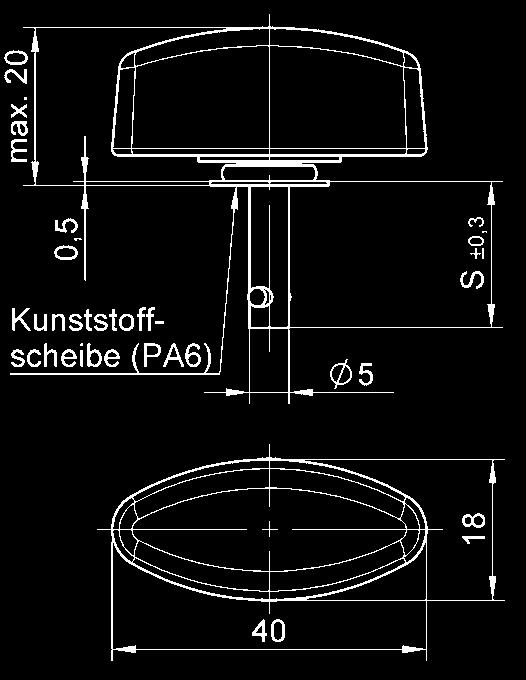
9 5F Series Features Max. tensile strength 670 N, working load 450 N. Plastic washer stud assembly to protect decorative surfaces. Spring loaded receptacle. Selection Instructions 1. Select stud assembly and receptacle, page B-2 und B Select retaining washer or grommet, page B Select stud length number from total thickness G using the formula and table below (e.g. V5S5-*AGV). With retaining washer G = P + F Determining the stud length number: With Grommet G = P + F + 1,4 G min = 3,9 mm Stud Length Table Total Thickness G Stud Length No. When Using Receptacles Other lengths on request. 0,50-0,90 1 0,90-1,30 2 1,30-1,65 3 1,65-2,05 4 2,05-2,40 5 2,40-2,80 6 2,80-3,20 7 3,20-3,55 8 3,55-3,95 9 3,95-4, ,30-4, ,70-5, ,10-5, ,45-5, ,85-6, ,20-6, ,60-7, ,00-7, ,35-7, ,75-8, ,15-8,50 21 Release March 2017 B-1
 100 V5S5- *AGV Steel / nickel-plated with plastic washer (PA6) 100 5S27-* S = 6,70 + (0,38 x length no.")
10 5F Series Stud Assemblies Style Dimensions Materials / Finish C Part No. Slotted Recess Head with plastic washer (PA6) 100 V5S5- *AGV Steel / nickel-plated with plastic washer (PA6) 100 5S27-* S = 6,70 + (0,38 x length no.) Cross Recess Head with plastic washer (PA6) 100 V5S21- *AGV Stainless steel with stainless steel washer (tensile strength 470 N max. working load 300 N) 200 5S15-* S = 6,70 + (0,38 x length no.) * Length no. from Table, page B-1. For installation dimensions see page B-3. B-2 Release March 2017

 black to 1,4 5S72-5-1AA 1,8-2,9 5S72-9-1AA Grommet P max G min 1,4 2,0 2,9 3,5 Panel thickness P over")
11 5F Series Stud Installation Instructions Installation Dimensions Accessories Material / Finish Panel Thickness P Part No. Retaining Washer Panel Thickness P up to 2,3 Retaining washer V5W3-1AG Retaining washer Installation: See page A-5 Panel thickness P over 2,3 Retaining washer Stainless steel 5S3-2 Retaining washer Installation: See page A-5 * For P up 1,4 : 5,6 for installation without retaining washer Snap-In Grommet Panel thickness P up to 2,9 Grommet Plastic (PA6) black to 1,4 5S72-5-1AA 1,8-2,9 5S72-9-1AA Grommet P max G min 1,4 2,0 2,9 3,5 Panel thickness P over 2,9 Grommet Release March 2017 B-3


12 5F Series Receptacle Style Dimensions Materials / Finish C Part-No. Type 1 Rivet / Screw Mounting Steel /zincflakecoated Stainless steel V5R2-1AK7 5R2-3 Receptacle Installation Instructions Dimensions Rivet / Screw Mounting B-4 Release March 2017
13 99F Series Features Max. tensile strength 700 N, working load 480 N. Increased grip range. Externally threaded receptacles for use in castings or on panels with a retaining nut (see page C-3). Encapsulated design, splash-proof. Selection Instructions 1. Select stud assembly and receptacle, page C-2 and C Select hex nut for receptacle, if necessary, page C Select stud retaining washer, page C Select stud length number from total thickness G using the formula and table below (e.g. 99S10-01AG). Determining the stud length number: G = P + X Total Thickness G 0,5-1,5 1,5-3,0 3,0-4,5 4,5-6,0 6,0-7,5 7,5-9,0 9,0-10,5 10,5-12,0 12,0-13,5 13,5-15,0 Stud Length No Other lengths on request. Release March 2017 C-1
 Installation Dimensions Panel Thickness P 0,5-3,2 Stud Installation Instructions Accessories Retaining washer Materials / Finish Stainless steel Part No.")
14 99F Series Stud Assemblies Style Dimensions Materials / Finish C Part No. Slotted Recess Head 100 V99S10-*AG 3,6 max when locked * Length no. from Table, see page C-1. S = 15,5 + (0,76 x length no.) Installation Dimensions Panel Thickness P 0,5-3,2 Stud Installation Instructions Accessories Retaining washer Materials / Finish Stainless steel Part No SW * For P up to 1,65 m 6,5 for installation without retaining washer Panel Thickness P over 3,2 Retaining washer Installation: See page A-6. Panel Thickness P 0,50-4,75 Retaining washer transparent passivated 99W10-01A1 Stainless steel V2600-LW-7 Retaining washer Installation: See page A-6. Mounting tool for retaining washer V2600-LW-7 and 99W10-01A1 T98-1 C-2 Release March 2017


15 99F Series Receptacles Style Dimensions Materials / Finish C Part No. Open Zinc die casting / zinc-plated, R10-01A1 Encapsulated Zinc die casting / zinc-plated, E10-01 Capsule: Stainless steel Receptacle Installation Instructions Installation Dimensions Accessories Materials / Finish Part No. Retaining nut Steel / zinc-plated, 99N10-01A1 Retaining nut Installation torque 3 Nm Tap 15/32-32 NS-2B Release March 2017 C-3
16
17 50F Series Features Max. tensile strength 900 N, working load 650 N. Stud assembly incorporates a plastic washer to protect decorative surfaces. Snap-in or clip-on spring loaded receptacle. Snap-in grommet for quick stud installation without a retaining washer. Selection Instructions 1. Select stud assembly and receptacle, page D-2 to D-4 and D Select retaining washer or grommet, page D Select stud length number from total thickness G using the formula and table below (e.g. 50E21-*AGV). Stud Length Table Total Thickness G Stud Length No. when using Receptacles Type 1 F= 1,0-2,1 Total Thickness G Stud Length No. when using Receptacles Type 2 F= 2,1-3,0 Total Thickness G Stud Length No. when using Receptacles Type 3 0,50-1,10 1,10-1,70 1,70-2,30 2,30-2,90 2,90-3,50 3,50-4,10 4,10-4,70 4,70-5,30 5,30-5,90 5,90-6,50 6,50-7,10 7,10-7,70 7,70-8,30 8,30-8,90 8,90-9,50 9,50-10,10 10,10-10,70 10,70-11,30 11,30-11,90 11,90-12,50 12,50-13,10 13,10-13,70 13,70-14,30 14,30-14,90 14,90-15,50 15,50-16, ,50-1,10 1,10-1,70 1,70-2,30 2,30-2,90 2,90-3,50 3,50-4,10 4,10-4,70 4,70-5,30 5,30-5,90 5,90-6,50 6,50-7,10 7,10-7,70 7,70-8,30 8,30-8,90 8,90-9,50 9,50-10,10 10,10-10,70 10,70-11,30 11,30-11,90 11,90-12,50 12,50-13,10 13,10-13,70 13,70-14,30 14,30-14,90 14,90-15,50 15,50-16, ,30-2,90 2,90-3,50 3,50-4,10 4,10-4,70 4,70-5,30 5,30-5,90 5,90-6,50 6,50-7,10 7,10-7,70 7,70-8,30 8,30-8,90 8,90-9,50 9,50-10,10 10,10-10,70 10,70-11,30 11,30-11,90 11,90-12,50 12,50-13,10 13,10-13,70 13,70-14,30 14,30-14,90 14,90-15,50 15,50-16,10 16,10-16,70 16,70-17,30 17,30-17, Other lengths on request. Release March 2017 D-1

 80 50E21-*AGV Plastic washer (PA6)")

 80 50E70-*AGV Plastic washer (PA6) S")
 Hex Head Slotted Recess with plastic")
 * Length no. from Table, see page D-1.")
18 50F Series Stud Assemblies Style Dimensions Materials / Finish C Part No. Slotted Recess Head with plastic washer (PA6) 80 50E21-*AGV Plastic washer (PA6) Stainless steel with plastic washer (PA6) 80 50E21-*S S = 11,40 + (0,6 x length no.) Cross Recess Head with plastic washer (PA6) 80 50E70-*AGV Plastic washer (PA6) S = 11,40 + (0,6 x length no.) Hex Head Slotted Recess with plastic washer (PA6) 80 50E90-*AGV Plastic washer (PA6) * Length no. from Table, see page D-1. S = 11,40 + (0,6 x length no.) D-2 Release March 2017

 S = 11,40 + (0,6 x")
 Fixed Wing Handle with plastic washer (PA6) 80")
 80 50E21-*WS S = 11,40 +")
 80 50E21-*W0AGV Plastic washer (PA6) S")
19 50F Series Stud Assemblies Style Dimensions Materials / Finish C Part No. Hex Recess Head with plastic washer (PA6) 80 50E60-*AGV Plastic washer (PA6) S = 11,40 + (0,6 x length no.) Fixed Wing Handle with plastic washer (PA6) 80 50E21-*WAGV Plastic washer (PA6) Stainless steel with plastic washer (PA6) 80 50E21-*WS S = 11,40 + (0,6 x length no.) Offset Fixed Wing Handle with plastic washer (PA6) 80 50E21-*W0AGV Plastic washer (PA6) S = 11,40 + (0,6 x length no.) * Length no. from Table, see page D-1. Release March 2017 D-3

 Star Form Handle Plastic with")
 Stainless steel with")
 Stainless steel with 50E82-*CP * Length no.")
20 50F Series Stud Assemblies Style Dimensions Materials / Finish C Part No. Folding Bail Handle 180 with plastic washer (PA6) 80 50E18-*AGV plastic washer (PA6) Star Form Handle Plastic with plastic head and plastic washer (PA6) - 40 up to E80-*AGV plastic washer (PA6) Stainless steel with plastic head and plastic washer (PA6) - 40 up to E80-*CP Fixed Wing Handle Plastic with plastic head and plastic washer (PA6) - 40 up to E82-*AGV plastic washer (PA6) Stainless steel with plastic head and plastic washer (PA6) - 40 up to E82-*CP * Length no. from Table, see page D-1. D-4 Release March 2017
 / natural colour Up to 1,60 50S12-0-1AA Working")


21 50F Series Stud Installation Instructions Style Dimensions Materials / Finish P Part No. Snap-In Grommet Grommet Plastic (PA6) / natural colour Up to 1,60 50S12-0-1AA Working temperature: -40 C C 1,70-2,80 50S12-1-1AA 2,90-4,00 50S12-2-1AA 4,10-5,30 50S12-3-1AA 5,40-6,65 50S12-4-1AA Grommet Retaining Washer Retaining washer Stainless steel 4002-SW-SS Ø 9,5 +0,2 Retaining washer Stainless steel 50E2-3BP Retaining washer Installation: see page A-5. Retaining washer Plastic (PA6) / natural colour 50W204-01K Working temperature: -40 C C ADVANTAGE: Plastic retaining washer can be assembled without tooling *For P up to 2mm Ø 8 +0,2 for installation without retaining washer Release March 2017 D-5

 Spring steel / zinc-flakecoated")


22 50F Series Receptacles Style Dimensions Materials / Finish Snap-In Spring steel / zinc-flakecoated Panel Thickness P F = 1,0-2,0 C Part No E20-1AK7 (Type 1) Spring steel / zinc-flakecoated F = 2,1-3, E20-2AK7 (Type 2) Max. tensile strength 250 N Clip-On Spring steel / zinc-flakecoated F = 0,8-5,6 170 V50R4-2-1AK7 (Type 3) Receptacle Installation Instructions Installation Dimensions Snap-In Clip-On clip-in D-6 Release March 2017
23 50F Series Features Max. tensile strength N, working load N. Small fastener giving high tensile load. Flat receptacle. High preload. Selection Instructions 1. Select stud assembly and receptacle, page E-2 to E-4 and E Select retaining washer, page E Select stud length number from total thickness G using the formula and table below (e.g. 50E8-*AGV). G = P + F Stud Length Table Total Thickness G 0,50-1,10 1,10-1,70 1,70-2,30 2,30-2,90 2,90-3,50 3,50-4,10 4,10-4,70 4,70-5,30 5,30-5,90 5,90-6,50 6,50-7,10 7,10-7,70 7,70-8,30 8,30-8,90 8,90-9,50 9,50-10,10 10,10-10,70 Stud Length No. Total Thickness G Stud Length No ,70-11,30 11,30-11, ,90-12,50 12,50-13,10 13,10-13,70 13,70-14,30 14,30-14,90 14,90-15,50 15,50-16,10 16,10-16,70 16,70-17,30 17,30-17,90 17,90-18,50 18,50-19,10 19,10-19,70 19,70-20,30 20,30-20, Other lengths on request. Release March 2017 E-1

 Cross Recess Head 120 50E71-*AGV max.")
 Hex Head Slotted Recess 120 50E91-*AGV max.")
24 50F Series Stud Assemblies Style Dimensions Materials / Finish C Part No. Slotted Recess Head E8-*AGV max. 5,9 when locked Stainless steel 1) E8-*S S = 11,4 + (0,6 x length no.) Cross Recess Head E71-*AGV max. 5,9 when locked S = 11,4 + (0,6 x length no.) Hex Head Slotted Recess E91-*AGV max. 10 when locked S = 11,4 + (0,6 x length no.) * Length no. from Table, page E-1. 1) Max. tensile strength N, working load N. E-2 Release March 2017


 Stainless steel 1) 120 200 50E8-*WAGV 50E8-*WS S = 11,4 +")
 Offset Fixed Wing Handle 120 50E8-*W0AGV max.")
25 50F Series Stud Assemblies Style Dimensions Materials / Finish C Part No. Hex Recess Head E61-*AGV Fixed Wing Handle max. 16 when locked max. 7,5 when locked S = 11,4 + (0,6 x length no.) Stainless steel 1) E8-*WAGV 50E8-*WS S = 11,4 + (0,6 x length no.) Offset Fixed Wing Handle E8-*W0AGV max. 16 when locked S = 11,4 + (0,6 x length no.) * Length no. from Table, page E-1. 1) Max. tensile strength N, working load N. Release March 2017 E-3


 -40 up to +60 50E81-*AGV Stainless")
 -40 up to")


 Max.")

26 50F Series Stud Assemblies Style Dimensions Materials / Finish C Part No. Folding Bail Handle max when locked E19-*AGV Star Form Handle Plastic with plastic knob (PA 6) -40 up to E81-*AGV Stainless steel 1) with plastic knob -40 up to E81-*CP Fixed Wing Handle Plastic with plastic knob (PA 6) -40 up to E83-*AGV Stainless steel 1) with plastic knob -40 up to E83-*CP Square Head E7-*AGV max 13,5 when locked max 9,2 when locked max 29 when locked max 23 when locked * Length no. from Table, page E-1. 1) Max. tensile strength N, working load N. E-4 Release March 2017


27 50F Series Stud Assemblies Installation Instructions Installation Dimensions Accessories Material / Finish Part No. Retaining washer (loose) Stainless steel 4002-SW-SS Ø 9,5 Retaining washer (fixed) Stainless steel 50E2-3BP Retaining washer Installation: see page A-5. Retaining washer (loose) Plastic (PA6) / natural colour Working temperature: -40 C C 50W204-01K *For P up to 2 mm 8 + 0,2 for installation without retaining washer ADVANTAGE: Plastic retaining washer to be assembled without tooling. Release March 2017 E-5

28 50F Series Stud Assemblies Style Dimensions Materials / Finish C Part No. Rivet- / Screw or Weld Mounting Rivet / Screw Mounting 120 V50R1-1-1AGV see version A or B Stainless steel 200 V50R1-1-1BP Welding Steel / zinc-plated - V50R1-1-2AZ Version A Rivet/Screw Mounting Steel / oil coated - V50R1-1-2AR Version B Welding Receptacle Installation Instructions Installation Dimensions Rivet- / Screw or Weld Mounting E-6 Release March 2017
29 2600/2700 Series Features Max. tensile strength N, working load 900 N. Small fastener giving a high tensile load. Wide range of stud head styles and receptacles. Selection Instructions 1. Select stud assembly and receptacle, page F-3 up to F-5, F-7 up to F Select stud accessories (retaining washer, gasket), page F-6 and F Select hex nut for receptacle, if necessary, page F Select stud length number from total thickness G using the formula and table on page F-2 (e.g. V26S01-*AGV). Determining the stud length number when using receptacle: Type 1 + 3* G = P + F * For Type 3: G = 9,9 mm min. Type 2 G = P + F (0,75 min.) Type 4 G = P + X (0,5 min.) Release March 2017 F-1
30 2600/2700 Series Stud Length Table Total Thickness G Stud Length No. When Using Type 1 Receptacles Total Thickness G Stud Length No. When Using Type Receptacles Total Thickness G Stud Length No. When Using Type 3 Receptacles 0,75-1,50 1,50-2,30 2,30-3,05 3,05-3,80 3,80-4,60 4,60-5,35 5,35-6,10 6,10-6,85 6,85-7,60 7,60-8,40 8,40-9,15 9,15-9,90 9,90-10,65 10,65-11,40 11,40-12,20 12,20-12,95 12,95-13,70 13,70-14,50 14,50-15,25 15,25-16,00 16,00-16,75 16,75-17,50 17,50-18,30 18,30-19,05 19,05-19,80 19,80-20,60 20,60-21,35 21,35-22,10 22,10-22,85 22,85-23,60 23,60-24,40 24,40-25,15 25,15-25,90 25,90-26,65 26,65-27,40 27,40-28,20 28,20-28,95 28,95-29,70 29,70-30,50 30,50-31, ,75-1,50 1,50-2,30 2,30-3,05 3,05-3,80 3,80-4,60 4,60-5,35 5,35-6,10 6,10-6,85 6,85-7,60 7,60-8,40 8,40-9,15 9,15-9,90 9,90-10,65 10,65-11,40 11,40-12,20 12,20-12,95 12,95-13,70 13,70-14,50 14,50-15,25 15,25-16,00 16,00-16,75 16,75-17,50 17,50-18,30 18,30-19,05 19,05-19,80 19,80-20,60 20,60-21,35 21,35-22,10 22,10-22,85 22,85-23,60 23,60-24,40 24,40-25,15 25,15-25,90 25,90-26,65 26,65-27,40 27,40-28,20 28,20-28,95 28,95-29,70 29,70-30, ,90-10,65 10,65-11,40 11,40-12,20 12,20-12,95 12,95-13,70 13,70-14,50 14,50-15,25 15,25-16,00 16,00-16,75 16,75-17,50 17,50-18,30 18,30-19,05 19,05-19,80 19,80-20,60 20,60-21,35 21,35-22,10 22,10-22,85 22,85-23,60 23,60-24,40 24,40-25,15 25,15-25,90 25,90-26,65 26,65-27,40 27,40-28,20 28,20-28,95 28,95-29,70 29,70-30,50 30,50-31,25 31,25-32,00 32,00-32,75 32,75-33,50 33,50-34,30 34,30-35,05 35,05-35,80 35,80-36,60 36,60-37,35 37,35-38,10 38,10-38,85 38,85-39,60 39,60-40, Other lengths on request. F-2 Release March 2017
 200 2600-*S Steel / nickel-plated 120 26S42-* S =")
 Cross Recess Pan Head 120 V26S02-*AGV max 5,2 when locked Steel / nickel-plated 120 26S39-* Stainless steel 1) 200 26S51-* S = ) Fixed Wing Handle 120 V26S04-*AGV")
31 2600 Series Stud Assemblies Style Dimensions Materials / Finish C Part No. Slotted Recess Pan Head 120 V26S01-*AGV max 5,2 when locked Steel / chrome-plated S38-* Stainless steel 1) *S Steel / nickel-plated S42-* S = 18,54 + (0,76 x Längen-Nr.) length no.) Cross Recess Pan Head 120 V26S02-*AGV max 5,2 when locked Steel / nickel-plated S39-* Stainless steel 1) S51-* S = 18,54 + (0,76 x Längen-Nr.) length no.) Fixed Wing Handle 120 V26S04-*AGV Stainless steel 1) *SW S = 16,76 18,54 + (0,76 x Längen-Nr.) length no.) * Length no. from Table, page F-2. 1) Max. Tensile strength N, working load 700 N. Release March 2017 F-3
 -40 up to +60 V26S06- *AGV max Ø 13 S Ø 6,3 8 Ø 3,2 Note: Not to be used with encapsulated receptacles Ref Ø 28 Fixed Wing Handle Plastic max")
32 2600 Series Stud Assemblies Style Dimensions Materials / Finish C Part No. Star Form Handle Plastic Ref 20 with plastic knob (PA6) -40 up to +60 V26S06- *AGV max Ø 13 S Ø 6,3 8 Ø 3,2 Note: Not to be used with encapsulated receptacles Ref Ø 28 Fixed Wing Handle Plastic max 17,5 with plastic knob (PA6) -40 up to +60 V26S07- *AGV max Ø 13 S Ø 6,3 8 Ø 3,2 Note: Not to be used with encapsulated receptacles Ref 26 Ref 11 Triangular Handle Plastic Ref 16 max Ø 13 with plastic knob (PA6) -40 up to +60 V26S08- *AGV S Ø 6,3 8 Ø 3,2 Note: Not to be used with encapsulated receptacles Ref Ø 30 * Length no. from Table, page F-2. F-4 Release March 2017

33 2600 Series Stud Assemblies Style Dimensions Materials / Finish C Part No. Knurled Head Steel / chrome-plated S34-* S = 16,76 + (0,76 x length no.) Folding Bail Handle V26S22 - *AGV * Length no. from Table, page F-2. Release March 2017 F-5
 200 2700-*S Cross Recess Flush Head S = 14,73 + (0,76 x length Längen-Nr.) no.")
34 2700 Series Stud Assemblies Style Dimensions Materials / Finish C Part No. Slotted Recess Flush Head 120 V27S01-*AGV Stainless steel 1) *S Cross Recess Flush Head S = 14,73 + (0,76 x length Längen-Nr.) no.) 120 V27S02-*AGV S = 14,73 + (0,76 x length Längen-Nr.) no.) * Length no. from Table, page F-2. 1) Max. Tensile strength N, working load 700 F-6 Release March 2017


 AN6227-B6 Rubber")
35 2600 Series Stud Installation Instructions Installation Dimensions Accessories Material / Finish Part No Retaining washer Stainless steel 2600-SW Retaining washer Stainless steel Not for chromeplated parts V2600-LW-7 Gaskets Rubber (100 C) AN6227-B6 Rubber (100 C) AN6227-B3 Release March 2017 F-7


36 2700 Series Stud Installation Instructions Installation Dimensions Accessories Material / Finish Part No Note: Dash 4 stud and smaller are selfcaptivating Retaining washer Stainless steel 2600-SW Note: Retaining rings are required for stud length dash numbers 5 and up Retaining washer Stainless steel V2600-LW-7 Steel / nickel-plated V27W01-1AN Stud Installation pliers 4P3-1 V2600-LW-7 and V27W01-1AN retaining washer installation tool T98-1 F-8 Release March 2017

37 2600/2700 Series Receptacles Style Dimensions Materials / Finish D C Part No. Type 1 Lightweight 2,6 120 V26R6-1AGV Type 1 Cast Hard bronze / zinc-plated, 2,5 120 V FGV Hard bronze / zinc-plated, 3,3 120 V FGV Stainless steel 2, S Type 1 Narrow Width Hard bronze / zinc-plated, 2,5 120 V212-12N-1FGV Type 1 Encapsulated Hard bronze / zinc-plated, 2, R16-1FGV Capsule: Stainless steel 2, R18-1-1AA Release March 2017 F-9

38 2600/2700 Series Receptacles Style Dimensions Materials / Finish C Part No. Type 2 Side Mounting Aluminium / anodized R1-1 Type 3 Rivet / Screw or Weld Mounting Weld nib Rivet / Screw Mounting Stainless steel V312-12AGV S Welding Stainless steel WS F-10 Release March 2017
39 2600/2700 Series Receptacles Style Dimensions Materials / Finish C Part No. Type 4 Single Hole Mounting Zinc die cast / zinc-plated, clear chromate R10-01A1 Type 4 Single Hole Mounting Encapsulated Zinc die cast / zinc-plated, clear chromate Capsule: Stainless steel E10-01 Release March 2017 F-11

40 2600/2700 Series Receptacle Installation Instructions Installation Dimensions Type Receptacles Hole Pattern Type 2 Receptacle Hole Pattern (Side Mounting) Installation Dimensions Installation Options Type 4 Receptacle Accessories Retaining nut Materials / Finish clear chromate Part No. 99N10-01A1 Retaining nut Fastening torque 3 +1 Nm Tap 15/32-32NS- 2B F-12 Release March 2017
41 Features Max. tensile strength N, working load N. Small fastener for high tensile load. Largerangeofstudassemblieswithfixedandfloatingreceptacles D4002 Series Selection Instructions 1. Select stud assembly, page G-4 and G-5, grommet and snap-on retaining ring, page G-7 and receptacle, page G-8 and G Select retaining washer, page G-6, for studs from length no Select stud length number from total thickness G using the formula and the table on page G-2 and G-3 (e.g. D4002-*AGV). Release March 2017 G-1
42 D4002 Series Stud Length Table When Using the Following Grommet and Receptacles: Flush Mounting Grommets D4002-G-AGV D4002-H-AGV 4002-GS 4002-HS Total Thickness G Stud Length No. When Using Type 1 Receptacles Total Thickness G Stud Length No. When Using Type 2 Receptacles Total Thickness G Stud Length No. When Using Type 3 Receptacles 0,50-1,30 1,30-2,05 2,05-2,80 2,80-3,55 3,55-4,30 4,30-5,10 5,10-5,85 5,85-6,60 6,60-7,30 7,30-8,15 8,15-8,90 8,90-9,65 9,65-10,40 10,40-11,20 11,20-11,95 11,95-12,70 12,70-13,50 13,50-14,20 14,20-15,00 15,00-15,75 15,75-16,50 16,50-17,30 17,30-18,00 18,00-18,80 18,80-19,55 19,55-20,30 20,30-21,10 21,10-21,85 21,85-22,60 22,60-23,40 23,40-24,15 24,15-24,90 24,90-25,65 25,65-26,40 26,40-27, ,50-1,30 1,30-2,05 2,05-2,80 2,80-3,55 3,55-4,30 4,30-5,10 5,10-5,85 5,85-6,60 6,60-7,30 7,30-8,15 8,15-8,90 8,90-9,65 9,65-10,40 10,40-11,20 11,20-11,95 11,95-12,70 12,70-13,50 13,50-14,20 14,20-15,00 15,00-15,75 15,75-16,50 16,50-17,30 17,30-18,00 18,00-18,80 18,80-19,55 19,55-20,30 20,30-21,10 21,10-21,85 21,85-22,60 22,60-23,40 23,40-24,15 24,15-24,90 24,90-25,65 25,65-26, ,90-9,65 9,65-10,40 10,40-11,20 11,20-11,95 11,95-12,70 12,70-13,50 13,50-14,20 14,20-15,00 15,00-15,75 15,75-16,50 16,50-17,30 17,30-18,00 18,00-18,80 18,80-19,55 19,55-20,30 20,30-21,10 21,10-21,85 21,85-22,60 22,60-23,40 23,40-24,15 24,15-24,90 24,90-25,65 25,65-26,40 26,40-27,20 27,20-27,95 27,95-28,70 28,70-29,50 29,50-30,20 30,20-31,00 31,00-31,75 31,75-32,50 32,50-33,30 33,30-34, ,20-27, ,40-27, ,05-34,80 35 Other lengths on request. G-2 Release March 2017
43 D4002 Series Stud Length Table When Using the Following Grommet and Receptacles: Plus Flush Mounting Grommets D4002-N-AGV D4002-O-AGV D4002-P-AGV 4002-NS 4002-OS D4002-P-BP Total Thickness G Stud Length No. When Using Type 1 Receptacles Total Thickness G Stud Length No. When Using Type 2 Receptacles Total Thickness G Stud Length No. When Using Type 3 Receptacles 0,50-1,30-0,50-1,30 2 8,90-9,65 3 1,30-2,05 2 1,30-2,05 3 9,65-10,40 4 2,05-2,80 3 2,05-2, ,40-11,20 5 2,80-3,55 4 2,80-3, ,20-11,95 6 3,55-4,30 5 3,55-4, ,95-12,70 7 4,30-5,10 6 4,30-5, ,70-13,50 8 5,10-5,85 7 5,10-5, ,50-14,20 9 5,85-6,60 8 5,85-6, ,20-15, ,60-7,30 9 6,60-7, ,00-15, ,30-8, ,30-8, ,75-16, ,15-8, ,15-8, ,50-17, ,90-9, ,90-9, ,30-18, ,65-10, ,65-10, ,00-18, ,40-11, ,40-11, ,80-19, ,20-11,95 11,95-12,70 12,70-13,50 13,50-14,20 14,20-15,00 15,00-15,75 15,75-16,50 16,50-17,30 17,30-18,00 18,00-18,80 18,80-19,55 19,55-20,30 20,30-21,10 21,10-21,85 21,85-22,60 22,60-23,40 23,40-24,15 24,15-24,90 24,90-25,65 25,65-26, ,20-11,95 11,95-12,70 12,70-13,50 13,50-14,20 14,20-15,00 15,00-15,75 15,75-16,50 16,50-17,30 17,30-18,00 18,00-18,80 18,80-19,55 19,55-20,30 20,30-21,10 21,10-21,85 21,85-22,60 22,60-23,40 23,40-24,15 24,15-24,90 24,90-25, ,55-20,30 20,30-21,10 21,10-21,85 21,85-22,60 22,60-23,40 23,40-24,15 24,15-24,90 24,90-25,65 25,65-26,40 26,40-27,20 27,20-27,95 27,95-28,70 28,70-29,50 29,50-30,20 30,20-31,00 31,00-31,75 31,75-32,50 32,50-33, ,40-27, ,65-26, ,30-34,05 35 Other lengths on request. Release March 2017 G-3


 Max.")
44 D4002 Series Stud Assemblies Style Dimensions Materials / Finish C Part No. Slotted Recess Head 120 D4002-*AGV Stainless steel 1) 200 D4002-*BP Cross Recess Head Steel / zinc-plated 120 D40S5-*AGV Stainless steel 1) 200 D40S5-*BP Fixed Wing Handle 120 D4002-*WAGV Stainless steel 1) 200 D4002-*WBP * Length no. from Table, page G-2 and G-3 1) Max. tensile strenght N, working load N G-4 Release March 2017


 Max. tensile strenght 3.")
45 D4002 Series Stud Assemblies Style Dimensions Materials / Finish C Part No. Folding Bail Handle D40S47-*AGV Star Form Handle Plastic -40 up to +60 D40E22-*AGV Hex Recess Head 120 D40E28- *AGV Stainless steel 1) 200 D40E28-*BP * Length no. from Table, page G-2 and G-3 1) Max. tensile strenght N, working load N Release March 2017 G-5


46 D4002 Series Stud Assemblies Style Dimensions Materials / Finish C Part No. Sealed Slotted Recess Head -15 to +80 D4002I-*AGV Gasket: Vulkollan * Available in Stud Length no. 4 and above Sealed Cross Recess Head -15 to +80 D40S5I-*AGV Gasket: Vulkollan * Available in Stud Length no. 4 and above * Vulkollan is a registered brand of Bayer AG. Installation Dimensions Accessories Materials / Finish Part No. Gasket to be ordered in addition to the sealed stud assembly Gasket Plastic / (PA6) D40S39-1K D40G11-3K Gasket Gasket EPDM black D40G11-3K D40S39 Gasket D40S39-1K Gasket 11,2 + _ 0,2 15,5 + _ 0,5 + _ 0,2 0,2 * Length no. from Table, page G-2 and G-3 G-6 Release March 2017


4002 Series. Release March 2017 G-7")
47 D4002 Series Stud Assemblies Installation Dimensions Accessories Materials / Finish Part No. retaining ring loose on stud use for stud length no. 5 and up Stainless steel 4002-SW-SS Stud Snap-on retaining ring Grommet Retaining washer retaining ring loose on stud use for stud length no. 5 and up Plastic 50W204-01K 4P3-1 installation pliers, see below Stud installation pliers 4P3-1 Mounting tool for retaining washers* 4002T02-1BP installation of 4002-SW-SS * Mounting tool 4002T02 is only for retaining washers of (D)4002 Series. Release March 2017 G-7


48 D4002 Series Grommets Style Dimensions Materials/ Finish C Part no. Plus Flush Mounting For Panel Thickness up to 1,65 Steel/ zinc-plated 120 D4002-N-AGV stainless steel NS Plus Flush Mounting For Panel Thickness from 1,65 to 2,40 Steel/ zinc-plated 120 D4002-O-AGV stainless steel OS Plus Flush Mounting For Panel Thickness from 2,40 to 3,20 Steel/ zinc-plated 120 D4002-P-AGV stainless steel 200 D4002-P-BP Plus Flush Mounting For Panel Thickness from 3,20 to 3,95 Steel/ zinc-plated 120 D4002-R-AGV stainless steel 200 D4002-R-BP Plus Flush Mounting For Panel Thickness from 3,95 to 4,75 Steel/ zinc-plated 120 D4002-S-AGV stainless steel 200 D4002-S-BP Plus Flush Mounting For Panel Thickness from 4,80 to 5,60 Steel/ zinc-plated 120 D4002-T-AGV stainless steel 200 D4002-T-BP Flush Mounting For Panel Thickness up to 1,65 Steel/ zinc-plated 120 D4002-G-AGV stainless steel GS Flush Mounting For Panel Thickness from 1,65 to 2,18 Steel/ zinc-plated 120 D4002-H-AGV stainless steel HS G-8 Release March 2017


49 D4002 Series Stud Assemblies Style Dimensions Materials/ Finish Part no. Steel/ zinc-plated, stainless steel stainless steel/ non-magnetic R4G-3 V40G26-1BP V40G26-1N grommet Grommet plus Flush Part no. P max snap-on retaining ring D4002-N-AGV / 4002-NS 1,65 D4002-O-AGV / 4002-OS 2,40 D4002-P-AGV / D4002-P-BP 3,20 D4002-T-AGV / D4002-T-BP 5,60 grommet Grommet Flush Part no. P max B max snap-on retaining ring D4002-G-AGV / 4002-GS 1,65 1,88 D4002-H-AGV / 4002-HS 2,18 2,97 grommet T26 snap-on retaining ring Release March 2017 G-9

50 D4002 Series Receptacles Style Dimensions Materials / Finish C Part No. Type 1 Cast Hard bronze / zinc-plated, 120 D214-16FGV Stainless steel S Type 1 Cast Narrow Width Hard bronze / zinc-plated, 120 D214-16NFGV Type 1 Cast Encapsulated Hard bronze / zinc-plated, Capsule: Brass / zinc-plated, 150 D40R12-1FGV G-10 Release March 2017
 Hard bronze / zinc-plated, 120 D244-16-FGV Cage: Stainless steel 200 244-16S Type 2 Float up to 0,75 mm Encapsulated Hard bronze / zinc-plated, 120")
51 D4002 Series Receptacles Style Dimensions Materials / Finish C Part No. Type 2 Float up to 0,75 mm (Cast Receptacle) Hard bronze / zinc-plated, 120 D FGV Cage: Stainless steel S Type 2 Float up to 0,75 mm Encapsulated Hard bronze / zinc-plated, 120 D244-16C-FGV Capsule: Stainless steel SC Type 3 Flat Rivet / Screw or Weld Mounting Rivet / Screw Mounting (A) Hard bronze / zinc-plated, 120 V50R1-1-1AGV see version A or B Stainless steel 200 V50R1-1-1BP Welding (B) Steel / zinc-plated - V50R1-1-2AZ Version A Steel/oil-coated - V50R1-1-2AR Version B Release March 2017 G-11
 Torlon, base plate: 120 V244-16T1 Torlon,")


52 D4002 Series Receptacles Style Dimensions Materials / Finish C Part No. Type 2 Float up to 0,75 mm (Torlon) Torlon, base plate: 120 V244-16T1 Torlon, base plate: Stainless steel 120 V244-16TS1 Type 2 Float up to 0,75 mm (Torlon) Encapsulated Torlon, base plate: 120 V244-16T1C Torlon. base plate: Stainless steel 120 V244-16TS1C Shim Aluminum t=0,8mm 175 D40W02-1DR Aluminum t=1,5mm 175 D40W02-2DR to be used with: D214-16FGV S D NFGV D40R12-1FGV G-12 Release March 2017
53 D4002 Series Receptacle Installation Instructions Installation Dimensions Types 1, 2 and 3 Receptacle Hole Pattern Release March 2017 G-13
54


55 991F Series Features Max. tensile strength N, working load N. High tensile strength and preload. Typical applications: Commercial vehicles, coaches, agricultural machinery, chemical engineering, heating systems etc. 1. Select stud assembly and receptacle, pages H-2, H-3 and H Sealed: Also select rubber gasket and buffer plate, page H Select retaining washer, page H Select stud length number from total thickness G using the formula and table below (e.g. 991S01-*AGV). Determining the stud length number when using: Rivet, Screw and Weld Mounting Receptacle Sealed Stud Assemblies Clip-On Receptacle G = P + F Pmin. = 4 F = 1,5-3,5 Stud Length Table Total Thickness G Stud Length No. Total Thickness G Stud Length No. Total Thickness G Stud Length No. 0,90-1,65 1,65-2,40 2,40-3,15 3,15-3,95 3,95-4,70 4,70-5,45 5,45-6,20 6,20-7,00 7,00-7,75 7,75-8,50 8,50-9,25 9,25-10,05 10,05-10,80 10,80-11,55 11,55-12,30 12,30-13,10 13,10-13, ,85-14,60 14,60-15,35 15,35-16,15 16,15-16,90 16,90-17,65 17,65-18,40 18,40-19,20 19,20-19,95 19,95-20,70 20,70-21,45 21,45-22,25 22,25-23,00 23,00-23,75 23,75-24,50 24,50-25,25 25,25-26,05 26,05-26, ,80-27,55 27,55-28,30 28,30-29,10 29,10-29,85 29,85-30,60 30,60-31,35 31,35-32,15 32,15-32,90 32,90-33,65 33,65-34,40 34,40-35,20 35,20-35,95 35,95-36,70 36,70-37,45 37,45-38,25 38,25-39, Other lengths on request. Release March 2017 H-1
 200 991S01- *-1BP S =")
 Fixed Wing Handle when locked 120 991S02- *-1AGV S = ) Offset Fixed Wing Handle when locked")
 Max. tensile strength 7.000 N, working load 4.500 N.")
56 991F Series Stud Assemblies Style Dimensions Materials / Finish C Part No. Hex Head Slotted Recess S01- *-1AGV when locked Stainless steel 1) S01- *-1BP S = 16,26 + (0,76 x length no.) Fixed Wing Handle when locked S02- *-1AGV S = 16,26 + (0,76 x length no.) Offset Fixed Wing Handle when locked S03- *-1AGV S = 16,26 + (0,76 x length no.) Star Form Handle Plastic -40 up to S04- *-1AGV S = 16,26 + (0,76 x length no.) * Length no. from Table, see page H-1. 1) Max. tensile strength N, working load N. H-2 Release March 2017


57 991F Series Stud Assemblies Style Dimensions Materials / Finish C Part No. Folding Wing Handle S05- *-1AGV when locked when locked S = 16,26 + (0,76 x length no.) Hex Recess Head max 12,5 when looked S30-*AGV when looked Folding Bail Handle 180 when locked S2991-*AGV * Length no. from Table, see page H-1. S = 15,03 + (0,76 X length no.) Release March 2017 H-3
 Sealed Stud Assemblies Installation Dimensions Accessories Material /")
58 991F Series Stud Installation Instructions Installation Dimensions Accessories Material / Finish Part No. Retaining washer Stainless steel 991W04-1BP Slotted retaining washer Stainless steel 991W02-1BP Retaining washer (optional) Sealed Stud Assemblies Installation Dimensions Accessories Material / Finish Part No. Buffer plate Stainless steel 991W03-1BP 16 max when locked Rubber gasket Retaining washer (optional) Buffer plate Rubber gasket NBR black (100 C max.) 991S17-1K H-4 Release March 2017
59 991F Series Receptacles Style Dimensions Materials / Finish Rivet / Screw Mounting 41,2 28,6 22,4 Rivet / Screw Mounting Mounting Ø C Part No. 3,3 4, R2-1AGV 991R2-3AGV 1,5 D Weld Schweissbuckel nib Stainless steel 3, R2-1BP 7,5 max. 1,2 Stainless steel 4, R2-3BP Welding Steel / zinc-plated R2-2AZ Steel / oil coated R2-2AR Clip-On zincflakecoated R6-1AK7 (17) Frame thickness F= 1,5mm - 3,5mm Receptacle Installation Instructions Installation Dimensions Rivet / Screw or Welded Mounting Clip-On Release March 2017 H-5
60

61 Release March 2017 One-Piece Fasteners
62


63 V936F Series Features Max. tensile strength 300 N, working load 200 N. Same hole shape for panel and frame. Available in slotted recess or knurled head styles. Fastener position indication by stud slot. Stud assembly captive in the panel. Vibration resistant. Grip ranges from 2,0 mm to 4,6 mm. Lock and unlock by a quarter turn. Typical applications are in electro-mechanical and electronic equipment. Quick installation without tools. Part no. example Knurled head for 3,3 mm to 4,6 mm grip range. V936 S AA Material / Finish Variant Grip range Style Series G = P + F Pmin = 1,2 mm Style Dimensions Materials / Finish A Slotted Recess Head Stud, spiral pin: clear chromate Compression spring: Stainless steel 12,3 ±0,3 14,8 ±0,3 Grip Range G 2,0-3,2 3,3-4,6 C Part No. 100 V936S05-3-1AA 100 V936S05-4-1AA Casing: Zinc die casting / zincplated, clear chromate Knurled Head Stud, Casing: Zinc die casting / zincplated, clear chromate 26,4 ±0,3 28,9 ±0,3 2,0-3,2 3,3-4, V936S11-3-1AA V936S11-4-1AA Compression spring: Stainless steel Spiral pin: clear chromate Release March 2017 I-1
64 V936F Series Installation Instructions Hole Shape in Panel P Installing the fastener The slot indicates the position of the fastener Unlocked Hole Shape in Panel F Fastener retained in panel Locked I-2 Release March 2017
65 713F Series Features This fastener fastens panels in electrical switch cabinets (e.g. 19 -equipment) to modular bars. Selection Instructions Thedimensionsofthefrontpanel andthemodularbaraswell asthecolourdeterminethefinal design of the fastener. To enable us to offer you the custom-tailored fastener, we need your drawings with the dimensions and tolerances of: 1. the front panel 2. the shape of the modular bar 3. the colour, if necessary In addition, please send us samples of your modular bar and front panel. Part no. example One-piece fastener 713 S* - * AE Materials / Finish Colour (as requested by the customer) Head style and design (as requested by the customer) Series Release March 2017 J-1
 Stud: Steel / nickel-plated Spring: clear chromate Casement fastener: Zinc die casting / zinc-plated, clear")
66 713F Series Modular Bar Fasteners Style Dimensions Materials / Finish C Part No. Slotted Recess Head Stud Spring Spring cup Casement fastener Spring cup: Plastic (POM) Stud: Steel / nickel-plated Spring: clear chromate Casement fastener: Zinc die casting / zinc-plated, clear chromate -25 up to S*- *AE Zapfen Feder Federtopf Vorreiber Knurled Head Stud Spring Spring cup Casement fastener Zapfen Feder Federtopf Vorreiber Spring cup: Plastic (POM) Stud: Steel / nickel-plated Spring: clear chromate Casement fastener: Zinc die casting / zinc-plated, clear chromate -25 up to S*- *AE * Design and colour as requested by the customer. Due to the various front panel thickness, hole shapes and modular bar shapes, it is not possible to offer one standard design.wewill individuallyissuethefinal partnumberonlyafterdeterminingthefrontpanel andmodularbardimensions and the colour. Dimensions Fastener Position Installing the Fastener Unlocked Locked To lock push stud and turn 90 C. 1. Insert fastener with spring cup into hole. 2. Push stud until snap-in hooks lock in. The slot indicates the position of the fastener. J-2 Release March 2017

67 Release March 2017 Push Button Fasteners
68
69 Inhaltsverzeichnis 15F Serie Series 15F Features Max. tensile strength N, working load 930 N. Quickopeningandclosingbyapushofthefinger. Easy installation with single hole mounting. Serie KNCM Selection Instructions 1. Select stud assembly, page K-2 or K-3 and receptacle, page K Select retaining washer, page K-2 and retaining hexnut, page K-3, if necessary. 3. Select stud length number from Panel thickness P or Panel distance G using the table below. Push Button Push Panel Stud Length Table Stud Length Table Panel Thickness P 0,7-2,3 2,3-3,8 3,8-5,3 5,3-6,9 6,9-8,4 8,4-9,9 9,9-11,4 11,4-13,0 Other lengths on request. Stud Length No Panel Distance G 4,6-5,3 5,3-6,1 6,1-6,9 6,9-7,6 7,6-8,4 8,4-9,1 9,1-9,9 9,9-10,7 10,7-11,4 11,4-12,2 Stud Length No Other lengths on request. Release March 2017 K-1 A-1
 * Length no. from Table Push Button, see page K-1. Other lengths and surfaces can be ordered upon request.")
70 K-2 15F Series Stud Assemblies Style Dimensions Materials / Finish C Part No. Push Button Steel / nickel-plated S1- *-1AD Steel / zinc-plated S1- *-1AJ S=22,4 + (0,76 x length no.) * Length no. from Table Push Button, see page K-1. Other lengths and surfaces can be ordered upon request. Stud Installation Instructions Installation Dimensions Panel thickness up to 4,8 Accessories Materials / Finish Part No. Retaining washer Stainless steel 15S11-1CJ Panel thickness up from to 4,8 + up Retaining washer Installation Tool for 15S11-1CJ retaining washer T107-1 K-2 Release March 2017

71 15F Series Stud Assemblies Style Dimensions Materials / Finish C Part No. Push Panel Steel / zinc-plated S20- *-1AGV S=22,4 + (0,76 x length no.) * Length no. from Table Push Panel, see page K-1. Other lengths and surfaces can be ordered upon request. Installation Dimensions Stud Installation Instructions Push Panel Rivet-/ Screw Mounting Release March 2017 K-3

72 15F Series Receptacle Style Dimensions Materials / Finish C Part No. 15,2 Zinc die casting / zinc-plated 120 V15R13-1-1AB Installation Dimensions Receptacle Installation Instructions Accessories Hex Nut Materials / Finish Part No. V15R14-1-1AB Nut K-4 Release March 2017
73

74 Release March 2017 Push-Turn Fasteners
75
76 715F Series Features Max. tensile strength 700 N, working load 600 N. Easy and economic clip-in installation for stud and receptacle. Also suitable for automatic installation. 1/4turntoopen-closebyapushofthefinger. Due to their small size they are particularly suited for use in electrical engineering and electronics. Selection Instructions 1. Select stud assembly according to panel thickness P, page L-2 and spring clip according to frame thickness F, page L Select stud length number form panel thickness G using the table below, insert into stud part number * (e.g. 715S12-*-1BP). Part no. example Stud, slotted recess head 715 S BP Material / Finish Panel thickness P Length No. Style Series Stud Length Table Panel Thickness P Slotted Recess Head Stud Length No. Knurled Head Stud Length No. Panel Thickness P Slotted Recess Head Stud Length No. Knurled Head Stud Length No. 0,50-1,25 1,25-2,00 2,00-2,75 2,75-3,50 3,50-4,25 4,25-5,00 5,00-5,75 5,75-6, ,50-7,25 7,25-8,00 8,00-8,75 8,75-9,50 9,50-10,25 10,25-11,00 11,00-11,75 11,75-12, Other lengths on request. Release March 2017 L-1


77 715F Series Stud Assemblies Style Dimensions Materials / Finish Slotted Recess Head Stainless steel Spring cup: Plastic (POM) / black Panel Thickness P 0,5-1,0 1,0-1,5 C Part No. -25 up to S12- *-1BP 715S12- *-2BP 4,5 max when locked 1,5-2,0 715S12- *-3BP S = 13,25 + (0,75 x length no.) Knurled Head Stainless steel Spring cup: Plastic (POM) / black 0,5-1,0 1,0-1,5-25 up to S13- *-1BP 715S13- *-2BP 1,5-2,0 715S13- *-3BP 15 max when locked S = 13,25 + (0,75 x length no.) Installation Dimensions Stud Installation Instructions Panel up to 2 mm Panel over 2 mm L-2 Release March 2017
78 715F Series Receptacle Style Dimensions Materials / Finish Frame Thickness F Receptacle Stainless steel 0,5-1,0 1,0-1,5 C Part No. -25 up to R02-1BP 715R02-2BP 1,5-2,0 (See stud assembly) 715R02-3BP 2,0-2,5 715R02-4BP Installation Instructions Installation Dimensions Release March 2017 L-3
79
80 716F Series Features Max. tensile strength N, working load N. Easy and economic clip-in installation for stud and receptacle. Also suitable for automatic installation. 1/4turntoopen closewithapushofthefinger. Selection Instructions 1. Select stud assembly according to panel thickness P, page M-2 and spring clip according to frame thickness F, page M Select stud length number from panel thickness P using table below, insert into stud part number * (e.g. 716S12-*-1BP). Part no. example Stud, slotted recess head 716 S BP Material / Finish Panel thickness P Length No. Style Series Panel Thickness P 1,0-2,0 2,0-3,0 3,0-4,0 4,0-5,0 5,0-6,0 6,0-7,0 7,0-8,0 8,0-9,0 9,0-10,0 Stud Length Table Stud Length No Other lengths on request. Release March 2017 M-1
81 716F Series Stud Assemblies Style Dimensions Materials / Finish Slotted Recess Head 5,5 max when locked Stainless steel Spring cup: Plastic (POM) / black Panel Thickness P 0,5-1,0 1,0-1,5 1,5-2,0 2,0-2,5 2,5-3,0 C Part No. -25 up to S12- *-1BP 716S12- *-2BP 716S12- *-3BP 716S12- *-4BP 716S12- *-5BP (1,5 deep) S = 18,5 + length no. Knurled Head Stainless steel Spring cup: Plastic (POM) / black 0,5-1,0 1,0-1,5-25 up to S13- *-1BP 716S13- *-2BP 15,5 max when locked 1,5-2,0 716S13- *-3BP 2,0-2,5 716S13- *-4BP 2,5-3,0 716S13- *-5BP S = 18,5 + length no. * Length no. from Table, page M-1. Stud Installation Instructions Installation Dimensions Panel up to 3 mm Panel over 3 mm M-2 Release March 2017
82 716F Series Receptacle Style Dimensions Materials / Finish Frame Thickness F Spring Clip Stainless steel 1,0-1,5 1,5-2,0 C Part No. -25 up to R01-1B 720R01-2B 2,0-2,5 (See stud assembly) 720R01-3B 2,5-3,0 720R01-4B Installation Instructions Installation Dimensions Release March 2017 M-3
83
84 717F Series Features Max. tensile strength N, working load N. Robust design - high strength. Stud assembly with protective, compensating and retaining washers. Rivet or screw mounting spring receptacle. 1/4turntoopen-closebyapushofthefinger. Selection Instructions 1. Select stud assembly and spring clip, page N-2 and N Select compensating and retaining washers, page N Select stud length number from grip range G using the table below, insert into stud part number * (e.g. 717S01-*-1AGV). Part no. example Spring clip, rivet / screw mounting 717 S AGV Material / Finish Head style Length No. Series Griprange G 1,0-3,0 3,0-5,0 5,0-7,0 7,0-9,0 9,0-11,0 11,0-13,0 Stud Length Table Stud Length No Other lengths on request. Release March 2017 N-1


 / anthracite -40 up to +100 717W03-1K Retaining washer Plastic (PA6) / natural colour -40 up")
85 717F Series Stud Assemblies Style Dimensions Materials / Finish C Part No. Slotted Recess Head Steel/ zinc-plated -40 up to S01- *-1AGV S = 20,5 + (2 x length no.) Knurled Head Steel/ zinc-plated -40 up to S01- *-2AGV S = 20,5 + (2 x length no.) * Length no. from Table, see page N-1. Stud Installation Instructions Style Dimensions Materials / Finish C Part No. Protective washer Plastic (PA6) / natural colour -40 up to W02-1K Compensating washer Plastic (PU-foam) / anthracite -40 up to W03-1K Retaining washer Plastic (PA6) / natural colour -40 up to W01-1K N-2 Release March 2017

86 717F Series Receptacle Style Dimensions Materials / Finish C Part No. Rivet / Screw Mounting Steel /zincflakecoated -40 up to R01-1AK7 Installation Instructions Installation Dimensions Release March 2017 N-3
87
88 PT10 Series Features Max. tensile strength N, working load 800 N. 1/4turntoopen,closewithapushofthefinger Wide grip range Tool or hand operated Fast installation of snap-in spring receptacle. No tools required for the installation of the stud and washer. Tool operated stud has combination recess. Selection Instructions 1. Select stud assembly according to panel thickness P, page O-2 and spring clip according to frame thickness F, page O Select Compensating washer and Retaining washer, page O Select stud length number from panel thickness P using the formula and table below (e.g. 720S01-*B). Part no. example Stud, slot-cross recess 720 S01-1 B Material / Finish Length No. Style Series Panel Thickness P Slot-Cross Recess Length No. Wing Head Stud Length No. Dimension L +0,1/-0,2 Dimension (S) 1,00-4,00 4,00-7,00 7,00-10, Release March 2017 O-1


 see table page O-1 * Length no.")

89 PT10 Series Stud Assemblies Style Dimensions Materials / Finish C Part No. Slot-Cross Recess Head Stainless steel Washer: PA6 natural -20 up to S01-*B Washer L + (S) see table page O-1 Fixed Wing Handle Plastic Stainless steel Knob: PA6 black Washer: PA6 natural -20 up to S02-*B Washer L + (S) see table page O-1 * Length no. from Table, see page O-1. Stud Installation Instructions Installation Dimensions Hole preparation: O-2 Release March 2017


90 PT10 Series Stud Assemblies Style Dimensions Materials / Finish C Part No. Compensating Washer PU - Elastomer yellow -20 up to W01-2K Retaining Washer Polyamid natural -20 up to E15-1K Mounting Instructions A B Compensation Washer Compensation Washer Retaining Washer Retaining Washer Release March 2017 O-3

91 PT10 Series Receptacle Style Dimensions Materials / Finish Frame Thickness F Spring Clip Stainless steel 1,0-1,5 1,5-2,0 C Part No. -20 up to R01-1B 720R01-2B 2,0-2,5 720R01-3B 2,5-3,0 720R01-4B Installation Instructions Installation Dimensions O-4 Release March 2017

92 Release March 2017 Pawl Latches
93
orhand-operated(fixedwinghead). Clockwise locking 3/4 turn maximum. Part no. example Pawl Latches, slotted recess head, with decorative washer.")
 Spring: Stainless steel Slotted Recess Head with Decorative Washer Decorative washer Stud: Steel / zinc-plated 120")
94 V964L Series Features Wide grip range (total thickness G up to 15 mm). Suitable for a large range of applications. Easy installation with single-hole mounting. Eithertool-operated(slottedrecesshead)orhand-operated(fixedwinghead). Clockwise locking 3/4 turn maximum. Part no. example Pawl Latches, slotted recess head, with decorative washer. V964L AG Variant Head style (slotted recess) Style G = P + F Series Style Dimensions Materials / Finish C Part No. Slotted Recess Head Stud: Steel / zinc-plated 120 V964L01-1-1AG 2 (4 deep) Spring: Stainless steel Slotted Recess Head with Decorative Washer Decorative washer Stud: Steel / zinc-plated 120 V964L01-1-2AG Spring: Stainless steel Fixed Wing Handle Plastic Stud: Steel / zinc-plated -40 up to +100 V964L01-2-1AG Spring: Stainless steel Wing: Plastic (POM) black Release March 2017 P-1
95 V964L Series Installation Instructions Installation Dimensions Locked Unlocked P-2 Release March 2017


96 Features Variable grip fastener. Available in two grip ranges from 1,0 mm to 18,8 mm. Tool or hand operated head styles available. Single hole mounting - low installation cost. Clockwise locking as standard. Counterclockwise locking fasteners upon request. V965L Series Part no. example Pawl Latches, Flat head. Grip range 1,0 mm - 12,2 mm. V965L 23-1 R1AG Locking Direction Grip Range (1,0 mm - 12,2 mm) Head Style G = P + F Series Style Dimensions Materials / Finish C Part No. Flat Head Grip Range 1,0 up to 12,2 Steel / zinc-plated -40 up to +100 V965L23-1R1AG Grip range 1,0 up to 12,2 Retaining washer closing angle 90 Flat Head Grip Range 7,6 up to 18,8 Steel / zinc-plated -40 up to +100 V965L23-2R1AG Grip range 7,6 up to 18,8 Retaining washer closing angle 90 Release March 2017 Q-1


97 V965L Series Pawl Latches Style Dimensions Materials / Finish C Part No. Knurled Head Grip Range 1,0 up to 12,2 Steel / zinc-plated -40 up to +100 V965L1-1R1AG Grip range 1,0 up to 12,2 Retaining washer Pawl position indicator closing angle 90 Knurled Head Grip Range 7,6 up to 18,8 Steel / zinc-plated -40 up to +100 V965L1-2R1AG Grip range 7,6 up to 18,8 Retaining washer Pawl position indicator closing angle 90 Pawl Latches Installation Instructions Instruction Dimensions Clockwise locking Q-2 Release March 2017
98 Index Part No. Page Part No. Page Part No. Page 15/32-32NS-2B C3,F12 15S1- *-1AD K2 15S1- *-1AJ K2 15S11-1CJ K2 15S20-*-1AGV K S F S G S G SC G *S F *SW F SW C2,F7,F8 26R1-1 F10 26R16-1FGV F9 26R18-1-1AA F9 26S34-* F5 26S38-* F3 26S39-* F3 26S42-* F3 26S51-* F *S F S F WS F GS G HS G NS G OS G SW-SS D5,E5,G7 4002T02-1BP G7 4P3-1 F8,G7 50E15-1K O3 50E18-*AGV D4 50E19-*AGV E4 50E20-1AK7 D6 50E20-2AK7 D6 50E21-*AGV D2 50E21-*S D2 50E21-*W0AGV D3 50E21-*WAGV D3 50E21-*WS D3 50E2-3BP D5,E5 50E60-*AGV D3 50E61-*AGV 50E7-*AGV 50E70-*AGV 50E71-*AGV 50E8-*AGV 50E8-*S 50E8-*W0AGV 50E8-*WAGV 50E8-*WS 50E80-*AGV 50E80-*CP 50E81-*AGV 50E81-*CP 50E82-*AGV 50E82-*CP 50E83-*AGV 50E83-*CP 50E90-*AGV 50E91-*AGV 50S12-0-1AA 50S12-1-1AA 50S12-2-1AA 50S12-3-1AA 50S12-4-1AA 50W204-01K E3 E4 D2 E2 E2 E2 E3 E3 E3 D4 D4 E4 E4 D4 D4 E4 E4 D2 E2 D5 D5 D5 D5 D5 D5,E5,G7 5R2-3 B4 5S3-2 B3 5S15-* 5S27-* 5S72-5-1AA 5S72-9-1AA 713S*- *AE 715R02-1BP 715R02-2BP 715R02-3BP 715R02-4BP B2 B2 B3 B3 J2 L3 L3 L3 L3 715S12- *-1BP L2 715S12- *-2BP L2 715S12- *-3BP L2 715S13- *-1BP L2 715S13- *-2BP L2 715S13- *-3BP L2 716S12- *-1BP M2 716S12- *-2BP M2 716S12- *-3BP M2 716S12- *-4BP M2 716S12- *-5BP M2 716S13- *-1BP M2 716S13- *-2BP M2 716S13- *-3BP M2 716S13- *-4BP M2 716S13- *-5BP M2 717R01-1AK7 N3 717S01- *-1AGV N2 717S01- *-2AGV N2 717W01-1K N2 717W02-1K N2 717W03-1K N2 720R01-1B M3,O4 720R01-2B M3,O4 720R01-3B M3,O4 720R01-4B M3,O4 720S01-*B O2 720S02-*B O2 720W01-2K O3 991R2-1AGV H5 991R2-1BP H5 991RZ-2AR H5 991R2-3AZ H5 991R2-3AGV H5 991R2-3BP H5 991R6-1AK7 H5 991S01- *-1AGV H2 991S01- *-1BP H2 991S02- *-1AGV H2 991S03- *-1AGV H2 991S04-*-1AGV H2 991S05- *-1AGV H3 991S17-1K H4 991S2991-*AGV H3 991S30-*AGV H3 991W02-1BP H4 991W03-1BP H4 991W04-1BP H4 Release March 2017
99 Release March 2017 Index Part No. Page 99E10-01 C3,F11 99N10-01A1 C3,F12 99R10-01A1 C3,F11 991R2-2AR H5 99W10-01A1 C2 AN6227-B3 F7 AN6227-B6 F7 D214-16FGV G10 D214-16NFGV G10 D FGV G11 D244-16C-FGV G11 D4002-*AGV G4 D4002-*BP G4 D4002-*WAGV G4 D4002-*WBP G4 D4002-N-AGV G8 D4002-O-AGV G8 D4002-P-AGV G8 D4002-P-BP G8 D4002-R-AGV G8 D4002-S-AGV G8 D4002-T-AGV G8 D4002-G-AGV G8 D4002-H-AGV G8 D4002I-*AGV G6 D40E22-*AGV G5 D40E28-*AGV G5 D40E28-*BP G5 D40G11-3K G6 D40R12-1FGV G10 D40S39-1K G6 D40S47-*AGV G5 D40S5-*AGV G4 D40S5I-*AGV G6 D40S5-*BP G4 D40W02-1DR G12 D40W02-2DR G12 R4G-3 G9 T107-1 K2 T26 G9 T98-1 C2,F8 V15R13-1-1AB K4 Part No. Page V15R14-1-1AB K4 V FGV F9 V FGV F9 V212-12N-1FGV F9 V244-16T1 G12 V244-16T1C G12 V244-16TS1 G12 V244-16TS1C G12 V2600-LW-7 C2,F7,F8 V26R6-1AGV F9 V26S01-*AGV F3 V26S02-*AGV F3 V26S04-*AGV F3 V26S06-* -1AGV F4 V26S07-* -1AGV F4 V26S08-* -1AGV F4 V26S22-*AGV F5 V27S01-*AGV F6 V27S02-*AGV F6 V27W01-1AN F8 V312-12AGV F10 V40G26-1BP G9 V40G26-1N G9 V50R1-1-1AGV E6,G11 V50R1-1-1BP E6, G11 V50R1-1-2AR E6,G11 V50R1-1-2AZ E6,G11 V50R4-2-1AK7 D6 V5R2-1AK7 B4 V5S21-*AGV B2 V5W3-1AGV B3 V5S5-*AGV B2 V936S05-3-1AA I1 V936S05-4-1AA I1 V936S11-3-1AA I1 V936S11-4-1AA I1 V964L01-1-1AG P1 V964L01-1-2AG P1 V964L01-2-1AG P1 V965L1-1R1AG Q2 V965L1-2R1AG Q2 V965L23-1R1AG Q1 Part No. Page V965L23-2R1AG Q1 V99S10-*AG C2

100 Camloc Tension Latches
101
102 Contents Page General Information... A-2 Important Information... A-3 Overview on latches... A-4 Tension Latches V934L Series... B-1 - B-2 95L Series... C-1 - C-2 V96L Series... D-1 - D L Series... E-1 - E-5 V951L Series... F-1 - F-6 V917L & 1449L Series... G-1 - G-5 V18L Series... H-1 - H-4 V46L Series... I-1 Slam Latches 2939L Series... J-1 52F Series... K L Series... L-1 - L-6 Index Release November 2016 A-1
103 General Information The Camloc brand was established in Since that time our fastening systems have been successfully integrated into numerous applications within many different industries. Ourcustomersbenefitfromourmorethan70yearsoffasteningexperience. We provide local support for innovative, high quality fastening systems supplied globally to the strictest environmental and working conditions. Certificate of Registration QUALITY MANAGEMENT SYSTEM - ISO/TS 16949:2009 Certificate of Registration ENVIRONMENTAL MANAGEMENT SYSTEM - ISO 14001:2004 This is to certify that: Alcoa Fastening Systems Kelkheim Operations Fairchild Fasteners Europe-Camloc GmbH Industriestrasse Kelkheim Germany This is to certify that: Alcoa Fastening Systems & Rings Kelkheim Operations Fairchild Fasteners Europe-Camloc GmbH Industriestrasse 6 Kelkheim Germany Holds Certificate No: TS and operates a Quality Management System which complies with the requirements of ISO/TS 16949:2009 for the following scope: Holds Certificate No: EMS and operates an Environmental Management System which complies with the requirements of ISO 14001:2004 for the following scope: Design and manufacture of fasteners and fastener solutions. Design and manufacture of fasteners and fastener solutions For and on behalf of BSI: Frank Lee, EMEA Compliance & Risk Director For and on behalf of BSI: Frank Lee, EMEA Compliance & Risk Director Issue Date: 07/04/2016 Latest Issue: 07/04/2016 Expiry Date: 14/09/2018 IATF Number: Page: 1 of 1 Original Registration Date: 05/07/2007 Effective Date: 18/03/2016 Latest Revision Date: 16/03/2016 Expiry Date: 14/09/2018 Page: 1 of 1 This certificate was issued electronically and remains the property of BSI and is bound by the conditions of contract. An electronic certificate can be authenticated online. Printed copies can be validated at or telephone +44 (0) Further clarifications regarding the scope of this certificate and the applicability of ISO/TS16949 requirements may be obtained by consulting the organization. IATF Contracted Office: BSI Group Americas Inc., Worldgate Drive, Suite 800, Herndon, VA USA. BSI (EMEA) Headquarters: 389 Chiswick High Road, London, W4 4AL, United Kingdom This certificate was issued electronically and remains the property of BSI and is bound by the conditions of contract. An electronic certificate can be authenticated online. Printed copies can be validated at or telephone +971 (4) Information and Contact: BSI, Kitemark Court, Davy Avenue, Knowlhill, Milton Keynes MK5 8PP. Tel: BSI Assurance UK Limited, registered in England under number at 389 Chiswick High Road, London W4 4AL, UK. ISO/TS 16949: 2009 DIN EN ISO : 2004 Pleasefindadditional informationaboutourenvironmental programunder: Your Alcoa Fastening Systems team Disclaimer: Parts listed are subject to technical changes. All dimensions in mm. All information is correct to the best of our knowledge at the time of printing. No liability for disadvantages caused by printing errors or false application. A-2 Release November 2016
104 Tension Latches Important Information How It Operates Drawhook center beyond common center line in locked position of base and strike Achsstift Pin Secondary Sicherung lock (optional) (Federraste) - push to unlock Handle Adjustable Base Rivet Stop drawhook Strike ntension latches provide a quick release yet secure locking mechanism. They can take high tensile loads. Shear forces must be kept off the tension latch by the assembly design. nthrough lever action, the panels connected with the tension latch and the strike are pulled together. If necessary, a stop must be provided. npositive lock is achieved when drawhook center is beyond the common center line of the base and strike. Pin Spring-steel drawhook Drawhook center beyond common center line in locked position Stroke nforunlocking,thesecondarylock,iffitted,isoperatedandthehandlelifted. For locking, the secondary lock automatically engages. nmost of the tension latches can be adjusted by a threaded drawhook. For non-threaded drawhook series the spring steel or wire drawhook gives tolerance compensation and joint tension. Release November 2016 A-3
105 Tension Latches Important Information Overview Latches Series Max. tensile strength Working load without secondary lock with secondary lock with hasp to rivit on or to screw on to weld on adjustable drawhook carbon steel with surface treatment Stainless steel Pages V934L 550 N 310 N B1-B2 95L 445 N 220 N C1-C2 V96L N 650 N D1-D2 1429L N N E1-E5 V951L N N F1-F6 V917L N N G1-G5 V18L N N H1-H4 V46L N N I1 * Limitations within series possible. Please see (foot) notes at catalogue pages. A-4 Release November 2016

106 V934L Series Max. tensile strength 550 N Working load 310 N Style Dimensions Materials / Finish Part No. Stainless steel V934L01-1-1BP V934L01-1-1AGV With secondary lock Stainless steel V934L01-1X1BP V934L01-1X1AGV secondary lock Strikes Style Dimensions Materials / Finish D Part No. Stainless steel 1) 2,6 V934L02-1BP V934L02-1AGV Release November 2016 B-1
107 V934L Series Installation Instructions Dimensions A A = min. 23,7 mm, please take into account the application preload and tolerance requirements B-2 Release November 2016


108 95L Series Max. tensile strength 445 N, working load 220 N Handle conceals all interior parts and strike Self-compensating spring steel drawhook Lowprofile Style Dimensions Materials / Finish Part No. Self-compensating spring steel drawhook Stainless steel V95L07-1-1BC Self-compensating spring steel drawhook Steel / chrome-plated Interiorparts: V95L15-1BD Strike Style Dimensions Materials / Finish Part No. Stainless steel V95H07-1-1BP Release November 2016 C-1
109 95L Series Installation Instructions Dimensions Spring steel drawhook tension latch / strike F V95L07-1-1BC C-2 Release November 2016


110 V96L Series Max. tensile strength N, working load 650 N. Handle conceals all interior parts and strike Self-compensating spring steel drawhook Lowprofile Style Dimensions Materials / Finish D Part No. Self-compensating spring steel drawhook 2,5 3,2 V96L01-1-1AO V96L01-1-2AO Steel / chrome-plated Interiorparts: 2,5 3,2 V96L01-1-1AG V96L01-1-2AG Strike Style Dimensions Materials / Finish D Part No. 2,5 3,2 V96H01-1-1AO V96H01-1-2AO Release November 2016 D-1

111 V96L Series Installation Instructions Dimensions * Ø D see selected version. D-2 Release November 2016

 Max.tensilestrength:450Nwith1429L8-1AGstrike,workingload330N. 2) Max.tensilestrength:300Nwith1429L8-1BPstrike,workingload210N.")
112 1429L Series Max. tensile strength N, working load up to N, see footnotes. Available with secondary lock Three different drawhook types available Style Dimensions Materials / Finish D Part No. Spring steel drawhook 1) 3,1 1429L02-1-1AG Stainless steel 2) 3,1 1429L02-1-1BP Wire drawhook 1) 3,1 1429L02-2-1AG Stainless steel 3) 3,1 1429L02-2-1BP 1) Max.tensilestrength:450Nwith1429L8-1AGstrike,workingload330N. 2) Max.tensilestrength:300Nwith1429L8-1BPstrike,workingload210N. 3) Max.tensilestrength:1.500Nwith1429L9-1AG/-1BPstrike,workingload1.000N. Release November 2016 E-1
 3,1 1429L02-3-1AG Stainless steel 1) 3,1 1429L02-3-1BP Spring steel drawhook and secondary lock 2) 3,1")
 Max.tensilestrength:450Nwith1429L8-1AGstrike,workingload330N. 3) Max.")
113 1429L Series Tension Latch Style Dimensions Materials / Finish D Part No. Hooked wire drawhook 1) 3,1 1429L02-3-1AG Stainless steel 1) 3,1 1429L02-3-1BP Spring steel drawhook and secondary lock 2) 3,1 1429L02-1X1AG Stainless steel 3) 3,1 1429L02-1X1BP 1) Max.tensilestrength:1.100Nwith1429L9-1AG/-1BPstrike,workingload800N. orinconjunctionwithmatingcomponentprofile. 2) Max.tensilestrength:450Nwith1429L8-1AGstrike,workingload330N. 3) Max.tensilestrength:300Nwith1429L8-1BPstrike,workingload210N. E-2 Release November 2016
 3,1 1429L02-2X1AG Stainless steel 1) 3,1 1429L02-2X1BP Hooked wire drawhook and")
 Max.tensilestrength:max.1.100Nwith1429L9-1AG/-BPstrike,workingload800N.")
114 1429L Series Tension Latch Style Dimensions Materials / Finish D Part No. Wire drawhook and secondary lock 1) 3,1 1429L02-2X1AG Stainless steel 1) 3,1 1429L02-2X1BP Hooked wire drawhook and secondary lock 2) 3,1 1429L02-3X1AG Stainless steel 2) 3,1 1429L02-3X1BP 1) Max.tensilestrength:max.1.500Nwith1429L9-1AG/-1BPstrike,workingload1.000N. 2) Max.tensilestrength:max.1.100Nwith1429L9-1AG/-BPstrike,workingload800N. orinconjunctionwithmatingcomponentprofile. Release November 2016 E-3

115 1429L Series Strikes Style Dimensions Materials / Finish D Part No. For use with spring steel drawhook 3,1 1429L8-1AG Stainless steel 3,1 1429L8-1BP For use with wire drawhook 3,1 1429L9-1AG Stainless steel 3,1 1429L9-1BP E-4 Release November 2016
116 1429L Series Installation Instructions Dimensions Spring steel drawhook tension latch / strike 1429L02-1-* 1429L8-* Wire drawhook tension latch / strike 1429L02-2-* 1429L9-* Hokkedwiredrawhooktensionlatch/matingcomponentprofile 1429L02-3-* (1429L9-*) Release November 2016 E-5
117
 D L Part No.")
118 V951L Series Max. tensile strength N, working load max N, see footnotes. Adjustable drawhook Available with secondary lock and hasp Style Dimensions Materials / Finish Mounting Type 1) D L Part No. Open base 2) N 3,6 14,3 V951L02-1-1AGV 2) N 4,2 12,7 V951L02-1-5AGV adjustable Base: Steel / zinc-plated 2) Steel / chrome-plated Interiorparts: 2) S N - 3,6-14,3 V951L02-1-2AGV V951L02-1-1AD Stainless steel 3) N 3,6 14,3 V951L02-1-1BP Stainless steel 3) N 4,2 12,7 V951L02-1-5BP Stainless steel 3) S - - V951L02-1-2BP Concealed base 4) N 3,6 14,3 V951L03-1-1AGV N 4,2 12,7 V951L03-1-5AGV adjustable Steel / chrome-plated Interiorparts: N 3,6 14,3 V951L03-1-1AD Stainless steel N 3,6 14,3 V951L03-1-1BP Stainless steel N 4,2 12,7 V951L03-1-5BP 1) Mountingtype: N=Withholesforrivetingorscrewfixing S = Without holes, for welding 2) Max.tensilestrength:2.300NwithV951L07-*A*andV951L52-1A*strike,workingload1.550N N with V951L50-1A* strike, working load N. 3) Max.tensilestrength:1.500NwithV951L07-*BPandV951L52-1BPstrike,workingload1.000N. 4) Due to the mounting geometry, tensile strength reduced to approx N, working load 800 N. Release November 2016 F-1
 N 3,6 14,3 V951L04-1X1AGV 2) N 4,2 12,7 V951L04-1X5AGV adjustable Steel / chrome-plated Interiorparts: Secondarylock: Stainless steel N 3,6 14,3")

119 V951L Series Tension Latch Style Dimensions Materials / Finish Mounting Type 1) D L Part No. Secondary lock, open base 2) N 3,6 14,3 V951L04-1X1AGV 2) N 4,2 12,7 V951L04-1X5AGV adjustable Steel / chrome-plated Interiorparts: Secondarylock: Stainless steel N 3,6 14,3 V951L04-1X1AD Stainless steel 3) N 3,6 14,3 V951L04-1X1BP Stainless steel 3) N 4,2 12,7 V951L04-1X5BP Stainless steel 3) S - - V951L04-1X2BP Secondary lock, concealed base 4) N 4,2 12,7 V951L03-1X5AGV adjustable Steel / chrome-plated Interiorparts: Secondarylock: Stainless steel Stainless steel N N 3,6 3,6 14,3 14,3 V951L03-1X1AD V951L03-1X1BP Stainless steel N 4,2 12,7 V951L03-1X5BP For footnotes refer to page F-1. F-2 Release November 2016
 N 4,2 V951L05-1X1AGV Stainless steel 3) N 4,2 V951L05-1X1BP adjustable Hasp 2) Base: Steel / zinc-plated S - V951L01-1Y2AGV Ø 2) N 4,2")
120 V951L Series Tension Latch Style Dimensions Materials / Finish Mounting Type 1) D Part No. Secondary lock, high base Secondarylock: Stainless steel 2) N 4,2 V951L05-1X1AGV Stainless steel 3) N 4,2 V951L05-1X1BP adjustable Hasp 2) Base: Steel / zinc-plated S - V951L01-1Y2AGV Ø 2) N 4,2 V951L01-1Y5AGV adjustable Hasp for Padlock Ø 6 max. For footnotes refer to page F-1. Release November 2016 F-3
 D Part No.")
 - V951L7-2AZ Steel / chrome-plated N")


")
 Material")
121 V951L Series Strikes Style Dimensions Materials / Finish Mounting Type 1) D Part No. Open N 3,6 V951L7-1AGV N 4,2 V951L7-5AGV Steel / zinc-plated S 2) - V951L7-2AZ Steel / chrome-plated N 3,6 V951L7-1AD Stainless steel N 3,6 V951L7-1BP Stainless steel N 4,2 V951L7-5BP Stainless steel S - V951L7-2BP Closed N 4,2 V951L50-1AGV Stainless steel N 4,2 V951L50-1BP Stainless steel N 3,6 V951L50-2BP Stainless steel S - V951L50-3BP Corner mounting N 4,2 V951L52-1AGV Stainless steel N 4,2 V951L52-1BP 1) Mountingtype: N=Withholesforrivetingorscrewfixing S = Without holes, for welding 2) Material C45,HRC36-39steel,pleaseusehigh-alloyfillerweldingrods F-4 Release November 2016
122 V951L Series Installation Instructions Dimensions Open-base tension latch / open strike (71,5) (Dimension for weld mounting) Select diameter D and distance L in accordance with the strike and tension latch style. Concealed-base tension latch / open strike (59) (Dimension for weld mounting) Select diameter D and distance L in accordance with the strike and tension latch style. Open-base tension latch / closed strike (100) (Dimension for weld mounting) (83,5) (Dimension for weld mounting) V951L02- V951L04- V951L01- V951L7- V951L03- V951L7- V951L02- V951L04- V951L01- V951L50- V951L05- Select diameter D and distance L in accordance with the strike and tension latch style. Release November 2016 F-5
123 V951L Series Installation Instructions Dimensions Concealed-base tension latch / closed strike (71) (Dimension for weld mounting) Select diameter D and distance L in accordance with the strike and tension latch style. Open-base tension latch / corner-mounting strike (70) (Dimension for weld mounting) Select diameter D and distance L in accordance with the strike and tension latch style. Concealed-base tension latch / corner-mounting strike (57,5) (Dimension for weld mounting) V951L03- V951L50- V951L02- V951L04- V951L01- V951L52- V951L03- V951L52- Select diameter D and distance L in accordance with the strike and tension latch style. F-6 Release November 2016

 N 5,1 V917L01-1-1AG Stainless steel 3) N 5,1 V917L01-1-1BP High base 2) N")
 Max.")
 Max.tensilestrength:3.")
124 V917L Series Max. tensile strength N, working load max N, see footnotes. Adjustable drawhook Available with secondary lock and hasp Style Dimensions Materials / Finish Mounting Type 1) D Part No. Open base 2) N 5,1 V917L01-1-1AG Stainless steel 3) N 5,1 V917L01-1-1BP High base 2) N 4,2 V17L12-1-1AA adjustable adjustable 1) Mountingtype: N=Withholeforrivetingorscrewfixing S = Without holes, for welding 2) Max.tensilestrength:3.200NwithV917L11-1-*AGstrike,workingload2.200N N with V951L50-1- *AGV strike, working load N. 3) Max.tensilestrength:3.600NwithV951L50-1-*BPstrike,workingload2.700N. max N with V917L11-1-1BP strike, working load N. Release November 2016 G-1
 D Part No.")
 N 5,1")
 S N - 5,1 V917L01-1X2BP")
 N")
 2 N 5,0")

125 V917L Series Tension Latch Style Dimensions Materials / Finish Mounting Type 1) D Part No. Secondary lock, open base 2) N 5,1 V917L01-1X1AG Stainless steel 3) N 5,1 V917L01-1X1BP adjustable Stainless steel 3) Stainless steel V4A 3) S N - 5,1 V917L01-1X2BP V917L01-1X1CP Stainless steel V4A 3) S - V917L01-1X2CP Secondary lock, high base 2) N 4,2 V17L12-2X1AA Secondary lock, for curved surfaces (R min = 125 mm) 2 N 5,0 1449L02-1X1AG Stainless steel 3) N 5,0 1449L02-1X1BP adjustable adjustable For footnotes refer to page G-1. G-2 Release November 2016


126 V917L Series Tension Latch Style Dimensions Materials / Finish Mounting Type 1) D Part No. Open base, with hasp 2 N 5,1 V917L01-1Y1AG Strikes Style Dimensions Materials / Finish Mounting Type 1) D Part No. Open 8,5 + _ 0, ,6 N 5,1 V917L11-1-1AG 12,5 + 1 _ 17,8 + 0,5 _ 5,5 N 4,2 V917L11-1-3AG 2 Ø D 11 Stainless steel N 5,1 V917L11-1-1BP Closed 8 max N 4,2 V951L50-1AGV 30,5 max adjustable N 5,1 V951L50-5AGV 2 Ø D 6 Stainless steel N 4,2 V951L50-1BP 12,7 Stainless steel S - V951L50-3BP For footnotes refer to page G-1. Release November 2016 G-3
127 V917L Series Installation Instructions Dimensions Open-base tension latch / open strike (98) (Dimension for weld mounting) Select diameter D in accordance with the strike style. Open-base tension latch / closed strike (105) (Dimension for weld mounting) Select diameter D in accordance with the strike style. Tension latch for curved surfaces V917L01- V917L11- V917L01- V951L L02- V951L50- Select diameter D in accordance with the strike style. G-4 Release November 2016
128 V917L Series Installation Instructions Dimensions High-base tension latch / open strike V17L12- V917L11- Select diameter D in accordance with the strike style. Release November 2016 G-5
129
 D Part No.")
 S - V18L01-1X2BF adjustable adjustable 1) Mountingtype: N=Withholeforrivetingorscrewfixing S = Without holes, for welding 2) Max.tensilestrength:6.")
130 V18L Series Max. tensile strength N, working load max N, see footnotes. Adjustable drawhook Available with secondary lock, hasp and lift spring Style Dimensions Materials / Finish Mounting Type 1) D Part No. 2) N 5,1 V18L01-1-1AA Stainless steel 3) N 5,1 V18L01-1-1BF Stainless steel 3) S - V18L01-1-2BF With secondary lock 2) N 5,1 V18L01-1X1AA Stainless steel 3) N 5,1 V18L01-1X1BF Stainless steel 3) S - V18L01-1X2BF adjustable adjustable 1) Mountingtype: N=Withholeforrivetingorscrewfixing S = Without holes, for welding 2) Max.tensilestrength:6.000NwithV18L13-1-1AAstrike,workingload4.200N. 3) Max.tensilestrength:4.600NwithV18L13-1-*BFor1449L07-1BPstrike,workingload3.100N. Release November 2016 H-1
 N 5,1 V18L01-1Y1AA adjustable Accessories Dimensions Materials / Finish Mounting Type 1) D Part No.")
131 V18L Series Tension Latch Style Dimensions Materials / Finish Mounting Type 1) D Part No. Hasp 2) N 5,1 V18L01-1Y1AA adjustable Accessories Dimensions Materials / Finish Mounting Type 1) D Part No. Lift spring Stainless steel N 5,1 V18L45-1BP Lift spring For footnotes refer to page H-1. H-2 Release November 2016
 D Part No.")

132 V18L Series Strikes Style Dimensions Materials / Finish Mounting Type 1) D Part No. Open 2) N 5,1 V18L13-1-1AA Stainless steel N 5,1 V18L13-1-1BF Stainless steel S - V18L13-1-2BF Closed Stainless steel N 5,0 1449L07-1BP For footnotes refer to page H-1. Release November 2016 H-3
133 V18L Series Installation Instructions Dimensions Tension latch / open strike (135,5) (Dimension for weld mounting) Tension latch / closed strike V18L01- V18L13- V18L L07- (135) (Dimension for weld mounting) H-4 Release November 2016


134 V46L Series Max. tensile strength N, working load N. Adjustable drawhook Style Dimensions Materials / Finish Mounting Type 1) D Part No. Steel / zinc-plated and yellow chromate N 6,3 V46L38-1-6AA Steel / zinc-plated and yellow chromate S - V46L38-1-1AA adjustable Strike Style Dimensions Materials / Finish Mounting Type 1) D Part No. Steel / zinc-plated and yellow chromate N 5,1 V18L13-1-1AC 1) Mountingtype: N=Withholeforrivetingorscrewfixing S = Without holes, for welding Release November 2016 I-1
135
 black -10 up to +60 2939L01-01-1K")

136 2939L Series Style Dimensions Materials / Finish C Part No. Slam latch Plastic (POM) black -10 up to L K Installation Instructions Dimension Locked Unlocked Frame * Other panel thicknesses upon request. Release November 2016 J-1
137


138 52F Series Wing Fastener Particular Features Simple and economic fastener for lids, etc. Easy installation by blind riveting. ¼ Turn to lock Secure locking on detent. Dimensions Materials / Finish C Part No. Mandrel E02-*-1AG Blind rivet Belleville spring washer Height H Selection and Installation Instructions Alternative 1 dimpled Riveted by standard blind rivet pliers. Breaking load 5000 N Wing fastener Slam Rivet - Ø 2,6 DIN 660 Frame DIN 660-2,5 Alternative 2 Panel Frame Part No. Panel Thickness P Height H 52E AG 52E AG 52E AG 0(flush) 1 2 0,7 1,1 1,7 Release November 2016 K-1
139


140 2812L Series Slam Latch Particular Features Robust slam latch, self locking Max.lockingforce:230N Max.tensionstrength:2.400N Max. torque:40nm Dimensions Materials / Finish Type C Part No. Steel / zinc-plated and yellow chromated Catch:zincflakecoated A L03-1AF Steel / zinc-plated and yellow chromated Catch:zincflakecoated B L03-2AF Release November 2016 L-1
141 2812L Series Slam Latch Dimensions Materials / Finish L C Part No. Steel / zinc-plated and yellow chromated Catch:zincflakecoated L05-1AF Steel / zinc-plated and yellow chromated Catch:zincflakecoated L05-2AF Steel / zinc-plated and yellow chromated Catch:zincflakecoated L06-1AF L-2 Release November 2016
142 2812L Series Slam Latch Dimensions Materials / Finish C Part No. Steel / zinc-plated and yellow chromated Catch:zincflakecoated L07-1AF Steel / zinc-plated and yellow chromated Catch:zincflakecoated L08-1AF Release November 2016 L-3
143 2812L Series Slam Latch Dimensions Materials / Finish C Part No. Steel / zinc-plated and yellow chromated Catch:zincflakecoated L09-1AF L-4 Release November 2016
144 2812L Series Slam Latch Dimensions Materials / Finish C Part No. Plastic (POM) / black -25 up to L80-1K tobeusedwith: 2812L03-1AF 2812L03-2AF 2812L08-1AF 2812L09-1AF Plastic (PA6) / black tobeusedwith: 2812L03-1AF 2812L03-2AF 2812L08-1AF 2812L09-1AF -40 up to L82-1K Release November 2016 L-5
145 2812L Series Installation Instructions Dimension Turn to unlock Frame Door (movable) Bale or locking bolt (not included) L-6 Release November 2016
146 Release November 2016 Index Part No. Page V18L13-1-2BF H3 V18L13-1-1AC I1 V18L45-1BP H2 V46L38-1-6AA I1 V46L38-1-1AA I1 V917L01-1-1AG G1 V917L01-1-1BP G1 V917L01-1X1AG G2 V917L01-1X1BP G2 V917L01-1X2BP G2 V917L01-1X1CP G2 V917L01-1X2CP G2 V917L01-1Y1AG G3 V917L11-1-1AG G3 V917L11-1-3AG G3 V917L11-1-1BP G3 V934L01-1-1AGV B1 V934L01-1X1AGV B1 V934L02-1AGV B1 V934L01-1-1BP B1 V934L01-1X1BP B1 V934L02-1BP B1 V95H07-1-1BP C1 V95L07-1-1BC C1 V95L15-1BD C1 V951L01-1Y2AGV F3 V951L01-1Y5AGV F3 V951L02-1-1AD F1 V951L02-1-1AGV F1 V951L02-1-1BP F1 V951L02-1-2AGV F1 V951L02-1-2BP F1 V951L02-1-5AGV F1 V951L02-1-5BP F1 V951L03-1-1AD F1 V951L03-1-1AGV F1 V951L03-1-1BP F1 V951L03-1-5AGV F1 V951L03-1-5BP F1 V951L03-1X1AD F2 V951L03-1X1BP F2 V951L03-1X5AGV F2 Part No. Page V951L03-1X5BP F2 V951L04-1X1AD F2 V951L04-1X1AGV F2 V951L04-1X1BP F2 V951L04-1X2BP F2 V951L04-1X5AGV F2 V951L04-1X5BP F2 V951L05-1X1AGV F3 V951L05-1X1BP F3 V951L50-1AGV F4,G3 V951L50-1BP F4,G3 V951L50-2BP F4 V951L50-3BP F4,G3 V951L50-5AGV G3 V951L52-1AGV F4 V951L52-1BP F4 V951L7-1AD F4 V951L7-1AGV F4 V951L7-1BP F4 V951L7-2AZ F4 V951L7-2BP F4 V951L7-5AGV F4 V951L7-5BP F4 V96H01-1-1AO D1 V96L01-1-1AG D1 V96L01-1-1AO D1 V96H01-1-2AO D1 V96L01-1-2AG D1 V96L01-1-2AO D1 Part No. Page 1429L02-1-1AG E1 1429L02-1-1BP E1 1429L02-1X1AG E2 1429L02-1X1BP E2 1429L02-2-1AG E1 1429L02-2-1BP E1 1429L02-2X1AG E3 1429L02-2X1BP E3 1429L02-3-1AG E2 1429L02-3-1BP E2 1429L02-3X1AG E3 1429L02-3X1BP E3 1429L8-1AG E4 1429L8-1BP E4 1429L9-1AG E4 1429L9-1BP E4 1449L02-1X1AG G2 1449L02-1X1BP G2 1449L07-1BP H3 2812L03-1AF L1 2812L03-2AF L1 2812L05-1AF L2 2812L05-2AF L2 2812L06-1AF L2 2812L07-1AF L3 2812L08-1AF L3 2812L09-1AF L4 2812L80-1K L5 2812L82-1K L5 2939L K J1 52E02-*-1AG K1 V17L12-1-1AA G1 V17L12-2X1AA G2 V18L01-1-1AA H1 V18L01-1-1BF H1 V18L01-1-2BF H1 V18L01-1X1AA H1 V18L01-1X1BF H1 V18L01-1X2BF H1 V18L01-1Y1AA H2 V18L13-1-1AA H3 V18L13-1-1BF H3
147
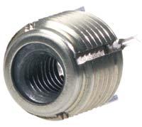
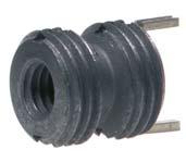
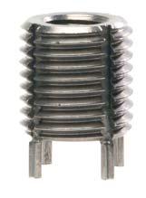
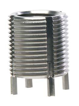
148
149
... B-3 - B-4 KNCA Series (miniature inserts imperial)... C-1 KNJ Series (lightweight inserts imperial).")
150 Contents Page General Information... A-2 Features of KEENSERTS... A-3 - A-4 Installation Instructions... A-5 KNCM Series (miniature inserts metric)... B-1 KNM Series (lightweight inserts metric)... B-2 KNHM Series (heavy duty inserts metric)... B-3 - B-4 KNCA Series (miniature inserts imperial)... C-1 KNJ Series (lightweight inserts imperial)...c-2 - C-3 KNHJ Series (heavy duty inserts imperial) C-4 - C-7 KNHXHJ Series (extra heavy duty inserts imperial)... C-8 - C-11 Release January 2017 A-1
151 General Information The Camloc brand was established in Since that time our fastening systems have been successfully integrated into numerous applications within many different industries. Ourcustomersbenefitfromourmorethan75yearsoffasteningexperience. We provide local support for innovative, high quality fastening systems supplied globally to the strictest environmental and working conditions. Certificate of Registration QUALITY MANAGEMENT SYSTEM - ISO/TS 16949:2009 Certificate of Registration ENVIRONMENTAL MANAGEMENT SYSTEM - ISO 14001:2004 This is to certify that: Alcoa Fastening Systems Kelkheim Operations Fairchild Fasteners Europe-Camloc GmbH Industriestrasse Kelkheim Germany This is to certify that: Alcoa Fastening Systems & Rings Kelkheim Operations Fairchild Fasteners Europe-Camloc GmbH Industriestrasse 6 Kelkheim Germany Holds Certificate No: TS and operates a Quality Management System which complies with the requirements of ISO/TS 16949:2009 for the following scope: Holds Certificate No: EMS and operates an Environmental Management System which complies with the requirements of ISO 14001:2004 for the following scope: Design and manufacture of fasteners and fastener solutions. Design and manufacture of fasteners and fastener solutions For and on behalf of BSI: Frank Lee, EMEA Compliance & Risk Director For and on behalf of BSI: Frank Lee, EMEA Compliance & Risk Director Issue Date: 07/04/2016 Latest Issue: 07/04/2016 Expiry Date: 14/09/2018 IATF Number: Page: 1 of 1 Original Registration Date: 05/07/2007 Effective Date: 18/03/2016 Latest Revision Date: 16/03/2016 Expiry Date: 14/09/2018 Page: 1 of 1 This certificate was issued electronically and remains the property of BSI and is bound by the conditions of contract. An electronic certificate can be authenticated online. Printed copies can be validated at or telephone +44 (0) Further clarifications regarding the scope of this certificate and the applicability of ISO/TS16949 requirements may be obtained by consulting the organization. IATF Contracted Office: BSI Group Americas Inc., Worldgate Drive, Suite 800, Herndon, VA USA. BSI (EMEA) Headquarters: 389 Chiswick High Road, London, W4 4AL, United Kingdom This certificate was issued electronically and remains the property of BSI and is bound by the conditions of contract. An electronic certificate can be authenticated online. Printed copies can be validated at or telephone +971 (4) Information and Contact: BSI, Kitemark Court, Davy Avenue, Knowlhill, Milton Keynes MK5 8PP. Tel: BSI Assurance UK Limited, registered in England under number at 389 Chiswick High Road, London W4 4AL, UK. ISO/TS 16949: 2009 DIN EN ISO : 2004 Pleasefindadditional informationaboutourenvironmental programunder: Your Alcoa Fastening Systems team Disclaimer: Parts listed are subject to technical changes. All dimensions in mm. All information is correct to the best of our knowledge at the time of printing. No liability for disadvantages caused by printing errors or false application. A-2 Release January 2017
152 Features Threaded Inserts are high strength threaded inserts made from stainless steel or AISI303. They are passivated according to EN 2516 or AMS Our standard product range contains metric and imperial thread dimensions. Specials are available upon request. can be used in alloys, light materials, steel and cast iron to give increased thread strength in these low strength materials. They are also be used for thread repair enabling the damaged thread to be replaced with the same size thread. Solidconfigurationgivesahighcyclelifewithmultipletighteningandlooseningof thebolt.lockinginsertshaveadryfilmlubricationonthesurfacetoprotectthescrewfromgalling. have a positive mechanical lock against rotation and vibration when kees are installed. Kees are made from stainless steel AISI302. have 2 or 4 pre-assembled kees depending on the size of the external thread. After installation of the kees into the parent material the assembly is positively locked in place. Pull-out-strength for. Calculation is as follows: Pull-out-strength(N) = shear engagement (mm 2 ) x ultimate shear strength of parent material (N/mm 2 ) Shear engagement areas are shown on the data sheets, only valid for full installed. Release January 2017 A-3
153 Features Part-no. example: Thepart-no.formetric arecodedasfollows: KN H M L 8 X 1,25 inside thread diameter x pitch locking type metric heavy duty series Thepart-no.forimperial arecodedasfollows: KN H XH L 4 28 J designates MIL-S-8879 interneal thread number of internal threads per inch internal threads diameter in 1/16 inch increments (e.g. 4 = 4/16 = 1/4 ) locking type extra heavy duty heavy duty series A-4 Release January 2017
 - drive the kees into place by hand or in a press with the appropriate installation tool")


154 Installation Instructions Installation: Drill - with standard drill Countersink - with cone countersink ( ) Thread Screw in Lock in Place - with standard tap - by hand or with installation tool (see installation data pages B-1 to B-4) - drive the kees into place by hand or in a press with the appropriate installation tool Installation depth of the The installed depth of the is determined by the pre-assembled kees. is based on the depth of the countersink. Installation in hard materials For very hard materials with a hardness greater than 30 HRC or 300 Vickers it is necessarytopre-broachtheslotsforthekees.thefirststepistomarkthepositionof the kees on the parent material. To do this wind the in until the kees touch the surface of the parent material. Mark the positions of the kees and unwind the. Then line up the blades of the broaching tool with the marked positions and push it in with a hammer or under a press, remove the tool and install the. In some cases it may be necessary to run the tap back down the hole to clear out any burrs. Available for external metrical thread M5 and up and external imperial thread 1/4 and up. Removal: 1. Drilling 2. Deflectkees 3. Remove insert 4. Insert new Dimensions see inward and with E-Z out as before pages B1 to B4 break off type tool Release January 2017 A-5
Alcoa Fastening Systems. Camloc Quick-Operating Fasteners
 Camloc Quick-Operating Fasteners Contents Page General Information... A-2 Important Information... A-3 - A-4 General Installation Instructions for 1/4-Turn Fasteners... A-5 1/4-Turn Fasteners 5F Series...
Camloc Tension Latches
 Camloc Tension Latches Contents Page General Information... A-2 Important Information... A-3 Overview on latches... A-4 Tension Latches V934L Series... B-1 - B-2 95L Series... C-1 - C-2 V96L Series...
2600/2700 Series. Determining the stud length number when using receptacle: Type 1 + 3* G = P + F. * For Type 3: G = 9,9 mm min.
 Particular Features Max. tensile strength 1.330 N. Small-size fastener for high tensile load. Wide variety of conventional stud assembly and receptacle designs. 2600 Series: Fillister head; 2700 Series:
4002 Series. Determing the stud length number when using receptacle: Type Type 3. G = P + F (8,9 min.) Release January 2009 G-1
 Release January 2009 G-1") Particular Features Max. tensile strength.00 N. Small-size fastener for high tensile load. Wide variety of conventional stud assembly and receptacle design. Floating receptacles available. Selection Instructions
Particular Features Max. tensile strength.00 N. Small-size fastener for high tensile load. Wide variety of conventional stud assembly and receptacle design. Floating receptacles available. Selection Instructions
QUICK OPERATING 1/4-TURN FASTENERS
 50F Series. General Purpose Stud Assemblies and Receptacles Features: Designed for use in agricultural, industrial, and similar environments where a simplified rugged design is desired. Studs are retained
Modularity and simplicity in action. ÂÂ Cost effective, easy to design and install
 84 E5 Cam Latches Overview Modularity and simplicity in action The SOUTHCO E5 cam latch is a highly modular and easy to configure solution, suitable for a wide range of applications. By changing any of
Indexing Plunger 417. Triangular Knobs, Made from Plastic. Triangular Knobs, Made from Stainless Steel
 Standard Parts for Operating - Overview Cam-Action Indexing Plungers / Indexing Plungers Cam-Action Indexing Plunger 612, Made from Steel and Stainless Steel Page 532 Page 533 Indexing Plunger 417 Indexing
D8 DZUS PANEX Quarter-Turn Fasteners
 392 DZUS ANEX Quarter-Turn Fasteners Studs Size 4 Studs: Steel, zinc plated plus chromate or chrome plated Bail cover: ABS, black H Head Styles - Tool Actuated Oval Slot Hex Recess hillips Recess 1.3 (.051)
E3 VISE ACTION Compression Latch
 38 E3 VISE ACTION Compression Latch Overview First 90 0 turn: rotates behind frame The door is now latched against opening Then as you complete the half-turn motion, the shaft and cam compress to pull
5F Series. Miniature Stud Assemblies and Receptacles
 5F Series. Miniature Stud ssemblies and Receptacles Features: Minimum stud head projection. Wide range of head styles. Variety of materials. Stud available with either retaining ring or snap-in grommet
Lift & turn series Flush style Adjustable grip. Door thickness Maximum 3 (.13) Gasket Door 27 (1.06) *Cup gasket 45 (1.78) 1 (.06)
 Gasket Door 27 (1.06) *Cup gasket 45 (1.78) 1 (.06)") 96 62 Compression Latch Lift & turn series Flush style Adjustable grip Low profile Easy grip adjustment Zinc alloy, powder coated or chrome plated and steel, zinc plated Maximum static load: 220N (50 lbf)
96 62 Compression Latch Lift & turn series Flush style Adjustable grip Low profile Easy grip adjustment Zinc alloy, powder coated or chrome plated and steel, zinc plated Maximum static load: 220N (50 lbf)
Door thickness Max. 3 (.13) Gasket Door 27 (1.06) *Cup gasket 45 (1.78) 1 (.06) Frame for top latching. R 0.5 (.02) Max. 8.6 (.34)
 Gasket Door 27 (1.06) *Cup gasket 45 (1.78) 1 (.06) Frame for top latching. R 0.5 (.02) Max. 8.6 (.34)") 64 62 Compression Latch Small Lift & turn series Flush style Adjustable grip Low profile when latched Zinc alloy, powder coated or chrome plated and steel, zinc plated Max. static load: 220N (50 lbf) Compression
64 62 Compression Latch Small Lift & turn series Flush style Adjustable grip Low profile when latched Zinc alloy, powder coated or chrome plated and steel, zinc plated Max. static load: 220N (50 lbf) Compression
Doors and fittings. Doors and fittings Aluminum Framing Hinge profile (p. 8-3) Hinge (p. 8-4) Hinge, plastic (p. 8-5)
 Hinge (p. 8-4) Hinge, plastic (p. 8-5)") Doors and fittings Aluminum Framing.0-1 Doors and fittings 1 4 Hinge profile (p. -) Hinge (p. -4) Hinge, plastic (p. -) Hinge, aluminum (p. -) 1 LIFTOFF hinge (p. -) Hinge, removable (p. -) Hinge, adjustable
Doors and fittings Aluminum Framing.0-1 Doors and fittings 1 4 Hinge profile (p. -) Hinge (p. -4) Hinge, plastic (p. -) Hinge, aluminum (p. -) 1 LIFTOFF hinge (p. -) Hinge, removable (p. -) Hinge, adjustable
64 Push-to-Close Latch
 244 64 Push-to-Close Latch Pull-to-open Paddle latch Miniature Plastic slide 11 (.42) Stainless steel, passivated and brushed finish and glass-filled reinforced nylon, black working load: 90 N (20 lbf)
Modularity and simplicity in action. A variety of materials and finishes to complement your application. Die-cast zinc latch bodies standard finishes:
 116 E5 Cam Latches Overview Modularity and simplicity in action The SOUTHCO E5 cam latch is a highly modular and easy to configure solution, suitable for a wide range of applications. By changing any of
Material: Hinge Parts: zinc die, matt chrome plated, or zinc die, matt black. Pin: stainless steel Nut plate: steel, zinc plated
 4-249 Hinge Pr01 180 Small elegant hinge. 180 Opening. Adjustments are possible with respective bores provided. The nut plate can be mounted in different ways, according to the application. zinc die, matt
AC-20 Multi Point Actuator
 29.6 (1.17) 51.1 (2.01) 29.6 (1.17) 51.1 (2.01) Cable B 52 27.3 (2.05) (.68) 27.3 (.68) 4X Ø 5.2 ± 0.1 (.210 ±.005) Cable A 29.6 (1.17) 17.3 (.68) 80.9 (3.19) 119 (4.7) (1.17) AC-20 Multi Point Actuator
Quarter-turn locks, compression latches
 Quarter-turn locks, compression latches 435 K0518 Quarter-turn locks small version 2,5 13,5 4,5 SW 20 Ø20 max. 5 Ø16,2 14,2 Housing and actuator die-cast zinc. Housing and actuator chrome-plated. Wing-handle
Slam-Cam Page. Material: a) Slam-Cam: zinc die, chrome plated Spring: steel, zinc plated Washer: Teflon
 Slam-Cam: zinc die, chrome plated Spring: steel, zinc plated Washer: Teflon") Slam-Cam Page 1-264 Slam-Cam for Slam Doors. Locking without key or tool. To a): The Teflon washer replaces the wave washer underneath the insert. Used with all Quarter- Turns and inserts according to
Slam-Cam Page 1-264 Slam-Cam for Slam Doors. Locking without key or tool. To a): The Teflon washer replaces the wave washer underneath the insert. Used with all Quarter- Turns and inserts according to
Quarter-Turn Pr20.1 L18
 1-100.01 Quarter-Turn Pr20.1 L18 for cutout 20.1, length 18, low profi le 15 Nm IP 65/67 Specially low profile Quarter-Turn. RH or LH application. This Quarter-Turn consists of three basic parts which
ACCESS SOLUTIONS NEW PRODUCTS BROCHURE.
 ACCESS SOLUTIONS NEW PRODUCTS BROCHURE www.essentraaccesssolutions.com ESSENTIAL SOLUTIONS DELIVERED NEW PRODUCTS Locks Hinges Gaskets Handles Stainless Steel Products Electronic p3-6 p13 14 p17-18 p7-8
LH: 21.1 GROUP CODE MATERIAL. Plastic. Keyed alike. 01 For cams please check page: Keyed differ Stainless steel dust cap (Keyed alike)
") 107 KNOB - ON LOCK 261 L: 21.1 27 Clip fixing for easy assembly. Mounting nut not required. Special 20mm x 26mm cut out. There is no IP 65 version of this lock. 1.8mm maximum panel thickness. Clips to
107 KNOB - ON LOCK 261 L: 21.1 27 Clip fixing for easy assembly. Mounting nut not required. Special 20mm x 26mm cut out. There is no IP 65 version of this lock. 1.8mm maximum panel thickness. Clips to
Cut out PRODUCT CODE HANDLE BODY FINISH MATERIAL MODUL. 5 mm Double bit 8 mm Square 9 mm Triangular Button. Stainless steel dust cap (Keyed alike) 03
 03") ROD-LATCH SYSTEM LINEAR HANDLE LOCK 204 V : 1 With mechanism Cut out Ergonomic and modern design Locking and unlocking by linear movement Suitable for inside & outside gasketing applications Swing handle
ROD-LATCH SYSTEM LINEAR HANDLE LOCK 204 V : 1 With mechanism Cut out Ergonomic and modern design Locking and unlocking by linear movement Suitable for inside & outside gasketing applications Swing handle
ACCESS SOLUTIONS. NEW PRODUCTS OVER
 OVER 250 NEW PRODUCTS ACCESS SOLUTIONS Search our range of over 2000 RoHS and REACH compliant parts, and find your industry solution across cabinet manufacturing, machine building, power generators, HVAC,
1-103 Slide Shoe for Cams
 1-103 Slide Shoe for Cams Slide shoe for cams, 2 parts, consisting of housing and latch. Matching cams as of 35 mm, steel product system 1.102 and stainless steel product system 7-080, in combination with
ABOUT KJN ALUMINIUM PROFILES
 P R O D U C T C ATA L O G U E ABOUT KJN ALUMINIUM PROFILES Our range of Aluminum Profile is available in a large range of sizes starting with 20 x 20 through to 100 x 200 making it suitable to use in all
Product Datasheet. Cable TV Junction Box (Page 4)
") JUNCTION BOX Product Datasheet Junction Box Bolted Type (Page 2) Cable TV Box (Page ) Cable TV Junction Box (Page 4) Telephone Box (Page 5) Telephone Junction Box (Page 6) GRP Junction Box Enclosures are
JUNCTION BOX Product Datasheet Junction Box Bolted Type (Page 2) Cable TV Box (Page ) Cable TV Junction Box (Page 4) Telephone Box (Page 5) Telephone Junction Box (Page 6) GRP Junction Box Enclosures are
Hinges and Flap Fittings Furniture Hinges
 Butt hinge Material: Steel Length: 50 mm Flange thickness: 1.5 mm Barrel Ø: 8 mm Crank A, straight Ø Gap1 mm Mounting Nickel plated matt Left 1.08.717 Right 1.08.708 Brass plated Left 1.08.511 Right 1.08.502
Operating instructions Actuator and Emergency exit AZ/AZM 200-B30 AZ/AZM 201-B About this document. Content
 1. About this document Operating instructions............pages 1 to 10 Original 1.1 Function This operating instructions manual provides all the information you need for the mounting, set-up and commissioning
CAM LOCKS CAM LOCK DD-CC ZAMAK - CHROME DD-CC ZAMAK - BLACK COATED DD-CC PLASTIC C C D D. web
 063 LOCK ø 063 1-1-DD-CC ZAAK - CHROE 063 1-2-DD-CC ZAAK - BLACK COATED 063 2-0-DD-CC PLASTIC Quarter-turn operation Body length 20.5 mm (Please be sure to order appropriate cam) Available in all die-cast
Cabinet & Drawer Hardware
 www.crh.com.au SOLUTIONS FOR TRADE Cabinet & Drawer Hardware November 2017 www.crh.com.au SOLUTIONS FOR TRADE CONTENTS Page 3 Page 4 5 Page 6 8 Page 9 10 Page 11 12 Page 13 14 Page 15 Page 16 18 Page 19
Keystone F89 pneumatic quarter-turn actuator General purpose / hazardous area
 Compact, reliable and low operation costs for all types of quarter-turn valves are the keywords of the Keystone F89 range of pneumatic actuators Features Direct mounting to all Keystone butterfly valves
KEYSTONE F89 pneumatic quarter-turn actuator GENERAL PURPOSE / HAZARDOUS AREA
 compact, reliable and low operation costs for all types of quarter-turn valves are the keywords of the Keystone F89 range of pneumatic actuators FEATURES Direct mounting to all Keystone butterfly valves
Selection Contents H Page No.
 CAMLOC LATCES Included in this catalog is a wide choice of tension latches, pawl latches, flush-mounted panel latches and chassis latches. Each design provides secure lock-up, quick operating action and
Series CP95. Profile Design ISO/VDMA Air Cylinder. Increased kinetic energy absorption. Improved end of stroke cushion capacity
 Profile Design ISO/VDMA Air Cylinder Series CP95 Improved end of stroke cushion capacity Piston rod lurching has been eliminated at the end of stroke positions by means of a floating seal mechanism. Increased
PLASTIC PIPE VALVES (PPV)
") PLSTI PIPE VLVES (PPV) THE EFINITIVE GUIE EITION 2 heatingthroughinnovation. the following scope: Member of the SI Group of ompanies. PLSTI PIPE VLVES (PPV) plastic Pipe Valves (PPV) Maximum versatility,
PLSTI PIPE VLVES (PPV) THE EFINITIVE GUIE EITION 2 heatingthroughinnovation. the following scope: Member of the SI Group of ompanies. PLSTI PIPE VLVES (PPV) plastic Pipe Valves (PPV) Maximum versatility,
Aero Materiel. Locks and latches
 Aero Materiel Locks and latches E3 Material and finish Zinc alloy, powder coated or chrome plated and steel plated Max static load 300N NEMA4/IP65 sealing is achieved by using optional flange gasket Recommended
19 Swell Action Latch
 150 19 Swell Action Latch Plastic ylon and glass-filled nylon black with rubber bushing Ø 2.4 (.09) Acorn nut M6 Thread 39 (1.53) Handle / tee shaft sub-assembly 1.5 (.059) 400 (90lbf) 2.5 (.098) 690 (155lbf)
THE ULTIMATE FASTENER SYSTEM
 THE ULTIMATE FASTENER SYSTEM Version A1 STEP 1 STEP 2 STEP 3 STEP 4 (98 DIFFERENT ITEMS) (108 DIFFERENT ITEMS) (104 DIFFERENT ITEMS) (103 DIFFERENT ITEMS) 4001 Plastic Fasteners 4023 Import Fasteners #1
AC Single Point Actuator
 130 AC Single Point Actuator T-handle Surface mount installation Generous grip area Pull to activate Cable clip 20.8 (.82) 21.7 (.85) 23 (.91) Housing: PC/ABS, black T-handle and slide: 33% glass-filled
Handle: 20" Chain: 25"
 Handle: 6" JTC-1147 6" CHAIN WRENCH Chain: 18" (400mm) Handle: 20" Chain: 25" JTC-1149 20" CHAIN WRENCH JTC-1150 12" STRAP WRENCH Handle: 12" Strap length: 36" JTC-1355 EUROPEAN DOOR HINGE / HANDLE KIT
Series CP95 ø32, ø40, ø50, ø63, ø80, ø100
 ISO Cylinder Series CP ø, ø, ø, ø, ø, ø0 Dimensions conform to ISO 6431, VDMA 2462, CETOP RP43P. CJ1 CJP CJ2 CM2 C8 C76 CG1 MB MB1 CP C C2 CA1 CS1 1.-1 Series CP Model Selection Execution Standard Type
Thread Forming Technology for Light Metals
 Thread Forming Technology for Light Metals Cost & Design Savings Advantages High joint strength Safety against dynamic loads Consistently high clamp loads Self-locking vibration resistance Easy lead-in,
Keystone F89C Pneumatic Quarter-Turn Actuator Chemical Industry / Hazardous area
 The F89C addresses the specific requirements for automated quarter-turn valves in the chemical industry on top of the reliability and low maintenance cost offered Features Valve connection compatible with
Operating instructions Solenoid interlock TKM/TKF. 1. About this document. Content
 1. About this document Operating instructions.............pages 1 to 6 Original 1.1 Function This operating instructions manual provides all the information you need for the mounting, set-up and commissioning
ARMA BAĞLANTI SİSTEMLERİ A.Ş.
 ARMA BAĞLANTI SİSTEMLERİ A.Ş. ARMA FIXING SYSTEMS, initially established as a molding workshop in 1980, is an innovative and dynamic company serving its customers in various sectors primarily automotive,
Hinges Gasketing Handles Stainless Steel Toggle Latches Compression Latches Quarter Turns Rod Controls Locking Systems
 Rod Controls Locking Systems Hinges Gasketing Handles Stainless Steel Toggle Latches Compression Latches Quarter Turns Locking Systems Hinges Gasketing Handles Stainless Steel Toggle Latches Compression
Quarter turns. Quarter turns J-1
 Quarter turns Further materials and surface finishes on demand. We will be pleased to give you advice. J-1 Quarter turns Quarter-turns have been inserted in the most varied technical ranges, because of
Polyester enclosures CP series
 Polyester enclosures CP series BERNSTEIN polyester enclosures from the CP and CPS series are made of high-quality glass-fibre reinforced polyester. The reduced surface resistance (RO
ay Manifold Mounted KHP3K
 3-Way ay Manifold Mounted Ball Valves KHP3K up to 500 bar up to DN 32 1. DESCRIPTION 1.1. GENERAL According to DIN 2429, FLUTEC 3/2-way manifold mounted ball valves are units for shutting off and diverting
Rittal CM Compact System Enclosures
 Rittal CM Compact System Enclosures Compact class = Top class: Infinite possibilities R Compact enclosure on the outside, Top enclosure on the inside! Index Convincing details... 3 5 Compact system enclosures
Components, Mounting Systems, In-roof PV Solutions FATH Solar About us Page 3
 Important matters Brochure Content Components, Mounting Systems, In-roof PV Solutions FATH About us Page 3 S1 System S1: Half as Complex and Twice as Safe Page 4 S1: Pivotal Advantage for all Standard
style vision & paddle latches paddle latches section section INDUSTRIAL, VEHICULAR & SPECIALTY SYSTEMS
 paddle latches vision & style paddle latches INDUSTRIAL, VEHICULAR & SPECIALTY SYSTEMS WE RE CHANGING THE FUTURE EBERHARD INDUSTRIAL, VEHICULAR & SPECIALTY SYSTEMS 1 paddle latches No. 4000 No. 4000 Mini
1967 (Late) and 1968 CORVETTE TELESCOPING STEERING COLUMN DISASSEMBLY & REPAIR INSTRUCTIONS - PAPER #1
 and 1968 CORVETTE TELESCOPING STEERING COLUMN DISASSEMBLY & REPAIR INSTRUCTIONS - PAPER #1") Last Revision: 03SE2012 1967 (Late) and 1968 CORVETTE TELESCOPING STEERING COLUMN DISASSEMBLY & REPAIR INSTRUCTIONS - PAPER #1 Disassembly and Repair Instructions Addressed in this Paper Difficulty Page
Last Revision: 03SE2012 1967 (Late) and 1968 CORVETTE TELESCOPING STEERING COLUMN DISASSEMBLY & REPAIR INSTRUCTIONS - PAPER #1 Disassembly and Repair Instructions Addressed in this Paper Difficulty Page
Rotary Medium Stylized wing 1.6 (.06) 1.3 (.05) 19 (.73) 48 (1.89) 1.6 (.06) 1.3 (.05) 18 (.71) 47 (1.85)
 1.3 (.05) 19 (.73) 48 (1.89) 1.6 (.06) 1.3 (.05) 18 (.71) 47 (1.85)") K Draw Latch Rotary Medium Stylized wing 1.6 (.06) 6.4 (.5) 9 (1.13) Stainless steel or steel, black powder coated Performance Details Steel: Max. working load: 130 N (75 lbf) Stainless steel: Max. working
K Draw Latch Rotary Medium Stylized wing 1.6 (.06) 6.4 (.5) 9 (1.13) Stainless steel or steel, black powder coated Performance Details Steel: Max. working load: 130 N (75 lbf) Stainless steel: Max. working
Product Datasheet. 2. GRP large rain canopy. 3. GRP door. 4. G.I Mounting plate. 5. G.I Gland plate. 6. EPDM rubber gasket
 POLYESTER ENCLOSURE SINGLE DOOR Product Datasheet GRP Single Door Enclosures are used for outdoor application with weatherproof and antistatic properties, finding their major application in the protection
HiBoy Maverick/Commander Doors Part # HiBoy4 Maverick/Commander Doors Black
 Racing 3191 N Washington St. Suite 2 Chandler, AZ 85225 1 (800) 708-9803 http://www.racing.com HiBoy Maverick/Commander Doors Part # 07-2001 HiBoy4 Maverick/Commander Doors Black Congratulations on your
Locks and Catches Information
 Information SYMO 3000 is the worldwide unique furniture locking system from Häfele. Without tools and time-consuming installation, it provides maximum flexibility at minimum expenditure and effort. The
Stirrup-shaped handles, machine handles, apparatus handles
 Stirrup-shaped handles, machine handles, apparatus handles 231 K0186 Stirrup-shaped handles GJS 400 Deburred and tumble cleaned; black plastic coated; machined contact faces. KIPP Stirrup-shaped handles
Locking System. White Paper
 Locking System White Paper Contents Introduction...4 Easy Integration...4 Benefits...4 Floor standing Mild steel...5 Floor standing Stainless steel... 10 Floor standing Aluminum... 15 Wall mounted Mild
Product features & Overview. N1 - N4 A Rotary and part-turn actuators
 Product features & Overview N1 - Rotary and part-turn actuators 20 N1 - Rotary and part-turn actuators Rotary and part-turn actuators Product features Wide torque range Wide selection of output shafts
KEYSTONE F89 PNEUMATIC QUARTER-TURN ACTUATOR GENERAL PURPOSE / HAZARDOUS AREA
 FEATURES Direct mounting to all Keystone butterfly valves and ball valves. Valve connection compatible with Keystone (imperial and metric) and ISO 5211. Double Rack and Pinion design nullifies side loads
SWING CHECK VALVES SERIES 52-SC SERIES 600
 SWING CHECK VALVES SERIES 52-SC SERIES 600 FEATURES/BENEFITS/SPECIFICATIONS AMERICAN Flow Control Series 52-SC Swing Check Valves incorporate design features to help increase service life for water and
Alcoa Fastening Systems
 ontents Page General Information... A-2 Features of KEENSERTS... A-3 - A-4 Installation Instructions... A-5 KNM Series (miniature inserts metric)... B-1 KNM Series (lightweight inserts metric)... B-2 KNHM
Suggested Specifications
 ISO 9001 Certified Suggested Specifications The Milliken criteria of quality, reliability, safety and value are embodied in the Millcentric Eccentric valve, setting higher standards for dependable performance
Pixus Technologies Catalog
 The Power of Embedded Ingenuity Pixus Technologies Catalog Kaparel, Ripac, & Vario Brand Products www.pixustechnologies.com sales@pixustechnologies.com US: 916.524.8242 CAN: 519.885.5775 Individual Subrack
Used for installation and dismantling designs such as pipes of almost any diameter. Handle: 20" Chain: 25"
 JTC-1147 6" CHAIN WRENCH Used for installation and dismantling designs such as pipes of almost any diameter. Handle: 6" Chain: 18" (400mm) JTC-1149 20" CHAIN WRENCH Used for installation and dismantling
Door, Hatch & Interior Fittings
 Sea Blue Security Locks NEW 10 Year Guarantee Sea Blue Security locks have been developed in the lock capital of England to withstand both corrosion and physical attack. Heavy steel full casings are used
Section 5 Doors and Door Components
 0 Section Whether you re looking for plain doors, locking doors, sliding doors, or large walk-through doors, you ll find what you need on the following pages. Bosch offers two basic types of doors that
New Products Inside DUMETA OVERVIEW CATALOGUE COMPONENTS
 New Products Inside DUMETA OVERVIEW CATALOGUE COMPONENTS 1 Modifications & Custom Components Diverse manufacturing capabilities and experienced on-site technical personnel allow Dumeta to offer a wide
B-250PD B-300PD B-500PD B-700PD B-800PD B-900PD
 ITEM : 71100 ISSUED: APRIL 19, 1993 REVISED: APRIL 26, 2001 HOSHIZAKI STORAGE BIN MODEL B-250PD B-300PD B-500PD B-700PD B-800PD B-900PD PARTS LIST B-250PD G-0 May, 1997 H-0 Dec., 1997 J-0 March, 1999 K-0
PT SS/MI - Pass Thru
 PT 2424-24 SS/MI - Pass Thru TABLE OF CONTENTS 1) 2) 3) 4) Pass Thru Brochure Pass Thru Drawing Operation Instructions Parts List Latch Info Hinge Info Spring Info Halco Warranty Pgs. 2-3 Pg. 4 Pgs. 6-8
Product Data For FARNELL
 ae Product Data For FARNELL ae Uniset is / Varioset is ae EL ELECTRONIC KOMBI SYSTEM WALL MOUNTING Pole clamp For reliable, convenient fastening to round or square poles. For pole diameter/size:
THE ENCLOSURE HARDWARE SUPPLIER
 FABTECH SUPPLY THE ENCLOSURE HARDWARE SUPPLIER Our Products JIC Style Enclosures JIC Style Cover Clamp Bracket... 5 JIC Style Cover Clamp... 6 JIC Style Cover Clamp Assembly... 6 JIC Cover Clamp Screws...
Catalogue Rivet Program
 Catalogue 2011 Program SFS Group SFS intec was incorporated in Switzerland in 1960, has since then had its headquarters in Heerbrugg, in St. Gallen Rhine valley and is now an internationally established
General Equipment Marker Boards. Air Reservoirs. Chassis Components. Content - Section 10. Chassis Components
 Content - Section Marker Boards Air Reservoirs.1 Tel: 01474 321954 / Fax: 01474 321988 / e-mail: orders@tube-gear.com UK Marker Boards Marker Boards to BSAU 152 1400mm Type 1 140mm 1 Aluminium 9901 140mm
Conveyors 12. slide strips roller Conveyors roller elements Conveyor rollers Chain Transfer
 Conveyors slide strips roller Conveyors roller elements Conveyor rollers Chain Transfer Application example conveyors Transport solutions and goods provision 1 2 3 4 5 6 7 8 362 9 1 slide strips Low-wear
DA/SR. Pneumatic Rotary Actuators FEATURES VALBIA ISO 9001 CERTIFIED
 VALBIA ISO 9001 CERTIFIED FEATURES Twin Rack and Pinion Design Constant Torque Output Compact Design Balanced Internal Forces Robust Design For Long Life Extruded Aluminum Body Hard Coat Anodized Smooth
Benteler Distribution. Steel tube solutions for hydraulic and pneumatic applications
 Benteler Distribution Steel tube solutions for hydraulic and pneumatic applications Benteler Distribution Customized steel tube solutions for challenging requirements Benteler Distribution is an internationally
Engineer The Lift!! HOIST RINGS. Applied Load Changes With Sling Angle. Sample Calculation: DO S DON TS
 H&O DIE SUPPLY, INC. 1-800-222-5441 sales@hodie.com HOIST RINGS 10 Adjustable Alloy Chain Sling... 10.16 Center Pull Style... 10.4-10.5 Envirolox Protective Finish... 10.11 Eye Bolts... 10.15 Eye Nuts...
Pneumatic Rotary Actuators
 ALEDER ISO 9001 CERTIFIED FEATURES Twin Rack and Pinion Design Constant Torque Output Compact Design Balanced Internal Forces Robust Design For Long Life Extruded Aluminum Body Hard Coat Anodized Smooth
1000/1200 Service Manual. 4j.1 - Vertical Stacker Main Chassis. Page 4j-1. SENSORS Item Description Part No. Wiring S1 Entry TX*
 Page 4j-1 5 Feb 2012 SENSORS Item Description Part No. Wiring S1 Entry TX* 182-443 5.49 *See section 4j-8 for corresponding RX 4j.1 - Vertical Stacker Main Chassis Page 4j-1 Page 4j-2 1 Mar 2012 4j.1 -
Secure footing. Easy levelling. Blickle levelling castors with integrated truck lock
 Secure footing. Easy levelling. Blickle levelling castors with integrated truck lock www.blickle.com 2 we innovate mobility www.blickle.com Blickle levelling castors Sturdy in use. Easy to use. The right
Low Pressure Series UF
 Low Pressure Couplings with various fitting shapes Due to differently shaped guide components (triangular, square, round) of coupling and adaptor only coupling halves with the same fitting may be connected.
Rolec aluplus. The PlUS in technology and design.
 Our passion is enclosures. The evolution in enclosure technology. Rolec aluplus. The PlUS in technology and design. 2 Rolec milestones in enclosure development. Our passion is enclosures. aluplus The evolution:
One-way flow control valves GR/GRA, in-line installation
 Product range overview and type codes Product range overview Version Valve function Version Type Connection direction In-line installation Metal One-way flow control function Pneumatic connection 1 GR/GRA
connected to innovation
 connected to innovation OMPRESSED IR NETWORKS, MPS ONEPT The MPS range MPS is a simple and reliable aluminium profile connection system for the installation of compressed air distribution networks. MPS
KNOCK CYLINDERS CONTENTS ACTUATORS GENERAL CATALOG. Caution KNOCK CYLINDERS
 CAD drawing data catalog is available. ACTUATORS GENERAL CATALOG CONTENTS Features/Introductions of Variations 79 Double Acting Type Specifications 81 Order s 82 Inner Construction and Major Parts 83 Dimensions
Last Revision: 07SE2009
 Last Revision: 07SE2009 1967 (Late) and 1968 CORVETTE STANDARD (NON-ADJUSTABLE) STEERING COLUMN DISASSEMBLY & REPAIR INSTRUCTIONS PAPER #1 Disassembly and Repair Instructions Addressed in this Paper Difficulty
Rolec aludisc. The round enclosure. Roundly complete.
 Our passion is enclosures. Project 20. An entirely new concept. Rolec aludisc. The round enclosure. Roundly complete. There are industries in which everything is round. Tanks. Pipes. lamps. Displays. Instruments.
Pre-Packaged Hardware
 New! Pre-Packaged Hardware Panel & Pilaster Packs 2-Ear Wall Bracket Headrail Bracket Wrap-Around Pivot Hinge () Strike / Keeper (Outswing) Slide (Outswing) Door Stop Door Hardware Packs The Story Originally
Installation, Maintenance & Parts Manual
 Installation, Maintenance & Parts Manual 00 Series Center Drive Conveyors Table of Contents Warnings General Safety........................... Introduction....................................... Product
CATALOG OF REPLACEMENT PARTS W32/W32C/625A WRAP STATION ML-44103, ML ML-44105, ML ML-26243
 CATALOG OF REPLACEMENT PARTS W32/W32C/625A WRAP STATION W32 W32C 625A HP ML-44103, ML-26320 ML-44105, ML-26331 ML-44069 ML-26243 A product of HOBART CORPORATION 701 S. RIDGE AVENUE TROY, OHIO 45374-0001
Aluminium Productive Fence System 40 PRODUCT CATALOGUE
 11 2017 (e) Aluminium Productive Fence System 40 PRODUCT CATALOGUE solutions by F.EE Elektrotech Engineering Automation Robotik Informatik + Systeme Energietechnik F.EE GmbH In der Seugn 10 and 20 D-92431
GoTo Europe Focused Delivery Program. Product overview assembly technology
 GoTo Europe Focused Delivery Program Product overview assembly technology 2 GoTo Europe Products you need, delivered when you need them In today s global competition every day counts. Fast response times
INTEGRATED HYDRAULIC BRAKE ACTUATORS
 INTEGRATED HYDRAULIC BRAKE INTEGRATED HYDRAULIC BRAKE INTEGRATED HYDRAULIC BRAKE The integrated hydraulic brake is comprised of a pneumatic cylinder that acts as an actuator and an oleo-dynamic circuit
Polycarbonate and ABS enclosures with quick release lid screws CT series
 Polycarbonate and s with quick release lid screws CT series The CT series of BERNSTEIN plastic enclosures are made from high-quality Polycarbonate or ABS. They are especially suitable for encapsulating
flow switches J with pipe tees (inline) J Direct installation (insertion) J for hvac applications J with interchangeable paddles J For air flow
 J Direct installation (insertion) J for hvac applications J with interchangeable paddles J For air flow") J with pipe tees (inline) J Direct installation (insertion) J for hvac applications J with interchangeable paddles J For air flow Including products with: UL 508 UL 353 CSA C22.2#14-10 flow switches J
J with pipe tees (inline) J Direct installation (insertion) J for hvac applications J with interchangeable paddles J For air flow Including products with: UL 508 UL 353 CSA C22.2#14-10 flow switches J
CATALOG OF REPLACEMENT PARTS
 CATALOG OF REPLACEMENT PARTS MODEL D300 SERIES MIXERS (INCLUDES MOTOR PARTS) ML-134258 ML-134261 D300T (Timed) D300C (Timed) PRIOR MLS COVERED IN THIS MANUAL ML-134211 ML-134213 ML-104421 ML-134114 D300T
INTERNATIONAL STANDARD
 INTERNATIONAL STANDARD First edition 1996-04-15 Connections for general use and fluid power - Ports and stud ends with IS0 261 threads with elastomeric or metal-to-metal sealing - Part 3: Stud ends with