Hydraulic Pumps and Motors Catalogue CAT.ASEAN_HYG_PAM_ASMR_MAY2017 (REV.1)
|
|
|
- Leon Ford
- 6 years ago
- Views:
Transcription


1 Hydraulic Pumps and Motors Catalogue CT.SEN_HYG_PM_SMR_MY2017 (REV.1)


2 Parker Hannifin Corporation Parker can be found on and around everything that move. We manufacture highly engineered components and systems that facilitate motion and the controlled flow of liquids and gasses for a wide variety of global markets to increase our customers productivity and profitability. From flying aircraft and building infrastructure; to developing more efficient energy, advancing medical science and engineered materials, providing clean food and water, and supporting military efforts. History Parker s,000 employees bring it all together, partnering with our customers to help solve some of the world s greatest engineering challenges ,000 58,151 13,000 1, The history of our great company is an interesting account of the transformation of technology over a period of nearly 100 years. Founded in 1918, the evolution of the Parker ppliance Company into Parker Hannifin Corporation illustrates a legacy of innovation. We believe our future growth is assured by honoring Parker s tradition of excellence and fair dealings. Founded Products Sold Customers Distribution/MRO Outlets Markets Manufacturing Plants Countries Solving The World s Greatest Engineering Our focus on solving some of the world s greatest engineering challenges sparks our passion for innovation and secures our future growth. The development of more efficient energy sources; the desire to produce and distribute clean water; new drug discovery and medical advances; the building of infrastructure and transportation to support a growing population; the safe cultivation, transportation and preservation of food sources; emerging developments in defense; and the protection of our environment all of these challenges drive Parker people forward, seeking new ways to innovate, combine technologies, collaborate, develop systems and partner with our customers to solve problems. Partnership in Motion From hidden costs to visible profits Partnership is an important aspect of the Parker Hannifin business philosophy. We feel that together we can increase your productivity and profitability by utilizing all the products, services and systems in our portfolio. Whether your needs is to develop sophisticated new machinery or to keep production lines running 24 hours a day, Parker is there to work with you to help you achieve your goals. ffice Presence (Head Office) Kuala Lumpur Penang Johor ahru Jakarta angkok (Head Office) Ho Chi Minh City Manila
3 Table of Content 1/ Fixed Displacement 5 Gear Pumps nd Motors 5 Quick View 6 Parker 500 Series 7 Parker 300 Series 20 Parker 600 Series 33 pplication Market 43 Literature 442 Vane Pumps 45 SDV Series 46 Single Pumps 49 Double Pumps 54 Triple Pumps 60 pplication Market 64 Literature Specifications 67 T Series 69 TE Series 71 Small Frame Options 73 TF Series 74 TG Series 76 TH Series 78 Large Frame Options 80 TK Series 82 Competitive Crossover 83 pplication Market 84 Literature xial Piston Pumps and Motors 86 xial Piston F11 Series 87 xial Piston F12 Series 90 pplication Market 95 Literature 96
4 Table of Content 2/ Variable Displacement 97 Pumps 98 Quick View 98 PVC Series 99 PVC - pplication Market/Literature 103 PVP Series 104 PVP - pplication Market/Literature 108 P1/PD Series 109 P1/PD - pplication Market/Literature 114 P2 Series 117 P2 - pplication Market 122 P2 - Literature 123 PV Plus Series 124 PV Plus - pplication Market 129 PV Plus - Literature 130 Motors 131 Quick View 131 V12 ent Piston Series 132 V14 ent Piston Series 134 pplication Market 138 Literature 139 Transmission 140 Hydrostatic Pumps Goldcup Series 141 Hydrostatic Motors Goldcup Series 147 pplication Market 149 Literature 150 3/Truck Pumps 151 Quick View 152 GP/GP1 Series 153 F1 Pumps 158 F1 Motors 162 F2 Twin-flow Pumps 164 VP1 Pumps 167 Suction Fittings 176 pplication Market 178 Literature 179 4/ppendix 180 Sizing 180 Useful Formula 181 Flow Capacity Chart 182 SE Flanges and Shafts olt SE Ports Sizes 184
5 Gear Pumps and Motors 1/ Fixed Displacement
 250.00 230.00 210.")

6 1/ Fixed Displacement Product Table Pressure vs. Displacement PGP 620 Pressure (ar) PGP 511 PGP 517 PGP Displacement (cc/rev) PGP 315 PGP 330 PGP 350 PGP 365 PGP 517 PGP/M 511 PGP/M 620 PGP/M 640 6


7 1/ Fixed Displacement Parker 500 Series 7
8 1/ Fixed Displacement Parker 500 Series Pump Displacement cm³/rev Max. Continuous Pressure bar Minimum 0 Inlet & Max. outlet pressure rpm Maximum 0 Inlet & Max. outlet pressure rpm Pump Input Max. Pressure and 1500 rpm kw Dimension "L" mm pproximate Weight 1) kg F L/ max. Pump Displacement cm³/rev Max. Continuous Pressure bar Minimum 0 Inlet & Max. outlet pressure rpm Maximum 0 Inlet & Max. outlet pressure rpm Pump Input Max. Pressure and 1500 rpm kw Dimension "L" mm pproximate Weight 1) kg L 112 across body max. F L/

9 1/ Fixed Displacement Parker 500 Series DISP DIMENSION MM INLET OUTLET PRT NUMER PRT NUMER cc/rev C "G" UNF "G" UNF Max RPM Max ar Clockwise CCW /8" 3/4" /16" 7/8" /16" 7/8" /16" 7/8" /16" 1-1/16" /16" 1-1/16" /16" 1-1/16" /16" 1 1/16" /8" 1-5/16" /8" 1-5/16" ø SHFT C L C L PORT G 17.6±0.13 ø


10 1/ Fixed Displacement DISP DIMENSION MM INLET OUTLET PRT NUMER ORDER CODE cc/rev C "G" UNF "G" UNF Max RPM Max ar Clockwise CCW /8" 3/4" /16" 7/8" /16" 7/8" /16" 1-1/16" /16" 1-1/16" /16" 1-1/16" /16" 1-1/16" /8" 1-5/16" /8" 1-5/16" /8" 1-5/16" ø SHFT C L C L PORT G v ø
11 1/ Fixed Displacement Parker 500 Series PGP511 Series luminium DISP DIMENSION MM INLET OUTLET ORDER CODE ORDER CODE cc/rev C "G" UNF "G" UNF Max RPM Max ar Clockwise CCW /8" 3/4" /16" 7/8" /16" 7/8" /16" 1-1/16" /16" 1-1/16" /16" 1-1/16" /16" 1-1/16" /8" 1-5/16" /8" 1-5/16" /8" 1-5/16" /8" 1-5/16" /8" 1-5/16" ø SHFT C L C L PORT G
12 1/ Fixed Displacem Parker 500 Series PGP511 Series luminium DISP DIMENSION MM INLET OUTLET ORDER CODE ORDER CODE cc/rev C "G" UNF "G" UNF Max RPM Max ar Clockwise CCW /8" 3/4" /16" 7/8" /16" 7/8" /16" 1-1/16" /16" 1-1/16" /16" 1-1/16" /16" 1-1/16" /8" 1-5/16" /8" 1-5/16" /8" 1-5/16" /8" 1-5/16" /8" 1-5/16" ø SHFT C L C L PORT G
13 1/ Fixed Displacement Parker 500 Series Ø G M12 x x Ø Ø
14 1/ Fixed Displacement Parker 500 Series 14
15 1/ Fixed Displacement Parker 500 Series Order Model cc/rev Shaft Mounting Seal Port (In & Out) Rotation Drain PGM H2NE3E311G3 6 9T, SE"" spline SE"" 2 bolts NR 1/2-12 SP I Top, 1/4 SP PGM K1H2NE3E311G4 8 Ø15.88, SE"" Key SE"" 2 bolts NR 1/2-12 SP I Rear, 1/4 SP PGM H2NE3E311G4 10 9T, SE"" spline SE"" 2 bolts NR 1/2-12 SP I Rear, 1/4 SP PGM H2NE3E311G4 11 9T, SE"" spline SE"" 2 bolts NR 1/2-12 SP I Rear, 1/4 SP PGM K1H2NE3E311G4 14 Ø15.88, SE"" Key SE"" 2 bolts NR 1/2-12 SP I Rear, 1/4 SP PGM K1H2NE3E311G4 16 Ø15.88, SE"" Key SE"" 2 bolts NR 1/2-12 SP I Rear, 1/4 SP PGM K1H2NE3E311G4 19 Ø15.88, SE"" Key SE"" 2 bolts NR 1/2-12 SP I Rear, 1/4 SP PGM K1H2NE3E311G4 23 Ø15.88, SE"" Key SE"" 2 bolts NR 1/2-12 SP I Rear, 1/4 SP PGM K1H2NE5E511G4 27 Ø15.88, SE"" Key SE"" 2 bolts NR 3/4-14 SP I Rear, 1/4 SP PGM K1H2NE5E511G6 31 Ø19.05, SE 19-1 Key SE"" 2 bolts NR 3/4-14 SP I Left, 1/4 SP PGM K1H2NE5E511G4 33 Ø15.88, SE"" Key SE"" 2 bolts NR 3/4-14 SP I Rear, 1/4 SP Spline SE 9T - 16/32 DP Flat root side fit Square key 4x4x Ø Ø Ø H2 131 max Ø Ø max
16 1/ Fixed Displacement Parker 500 Series Data Gear Pumps and Motors PG P M Type Pump Motor Side Ports Rear Ports Unit Pump Motor Single Unit Standard Motor w/o checks Standard Multiple Motor two Unit checks C --- Standard Motor one a/c check Displacement cc C Rotation Clockwise Counter Clockwise idirectional E3E3 D4D3 E5E3 D5D4 D6D5 E6E5 Port Options (pumps) 1/2-12 SP thread/ 1/2-12 SP thread for 4cc to 8cc 7/8-14 UNF Thread/ 3/4-14 UNF Thread for 4cc to 8cc 3/4-14 SP Thread 1/2-12 SP Thread for 4cc to 19cc 1-1/16 12UNF Thread 7/8-I4UNF Thread for 6cc to 23cc 1-5/16-12UNF Thread 1-1/16 12UNF Thread for 10cc to 33cc 1-11 SP Thread 3/4-14 SP Thread for 14cc to 33cc(*) Port Options (motors) 1/2-14 SP thread/ E3E3 1/2-14 SP thread/ only from 4cc to 11cc 3/4-14 SP thread E5E5 3/4-14 SP thread only from 14cc to 33cc 7/8-14 UNF thread D4D4 7/8-14 UNF thread only from 4cc to 11cc 1-5/16-12UNF thread/ D6D6 1-5/16-12UNF thread only from 14cc tp 33cc * ) Recommended Port 1900rpm 1 C1 K1 Shaft 9T, 16/32DP, 32L, SE "" spline 11T, 16/32DP, 38.2L, SE 19-4 spline , 4.0key, no thread, 32L SE "", parallel L , 4.8key, no thread, 32L SE 19-1, parellel S , 7.7L. 3.Okey. M12x1 5, taper 1:5 S , 12.0L, 3.2kev. M12x1.5. taper 1:8 S , 12.0L, 4.0kev. M2x1.5 taper 1:8 D3 D4 H2 H3 Q2 Q4 X N M Flange Shaft Seal No seal NR Double NR 71.4X rectangular 72.0X rectangular SE ' 2 bolt flange O1.06 SE "" 2 bolt flange 60.0x w eal O' thrubolt flange top RJHS 60.0 x w Seal O. thru bolt flange top LHS vailable Options - Relief Valve - Priority Flow Divider - Load Sensing Priority Valve - Over-run check valve 16
17 1/ Fixed Displacement Parker 500 Series Ø Ø
18 1/ Fixed Displacement Parker 500 Series Data PG Gear Pumps and Motors 1 P Type Pump Side Ports Rear Ports Pump Single Unit Displacement cc C D1 M1 M2 T1 Multiple Unit Rotation Clockwise Counter Clockwise Shaft 13T, 16/32DP, 41.2L, SE " spline Dia 22.2, 6.3 key, 41.2L SE '' parallel Dia 25.4, 6.3 key, 46L SE '' parallel SE "", parallel Dia 21.59, 11.2L 4.0 key M14 x 1.5 taper D7 H3 E6E5 E7E6 E8E6 Port Options (pumps) 1"-11 SPP thread 3/4" - 14 SPP thread from 16cc to 33cc(*) 1.1/4" - 11 SPP thread 1" - 11 SP thread only from 23cc to 38cc 1.1/2-11 SPP thread 1" - 11 SP thread for 44cc to 70cc * ) Recommended Port 1900rpm X N M Flange 98.4 x x pilot rectangular O1.06 SE "" 2 bolt flange Shaft Seal No seal NR Double NR 18
19 1/ Fixed Displacement Parker 500 Series Gear Pumps and Motors PGP 517 Drive Shaft D1 Spline SE 13T - 16/32 DP Flat root side fit Full spline Ø M Square key 6.3x6.3x Ø Ø M2 Square key 6.3x6.3x C 3 Ø 27 Ø

20 1/ Fixed Displacement Parker 300 Series Gear Pumps and Motors 300 Series Cast Iron Three-piece cast iron construction. Low friction bushing design. Heavyduty application. Single, multiple, piggyback and thru-drive assemblies. The PGP/PGM300 Series pumps and motors set the standard for superior performance and reliability in heavy-duty hydraulic application. The three-piece cast iron construction with large area, low-friction bushings provide strength, high efficiency, and long life in severe operating environments. The design includes an advanced thrust plate and seal configuration, which optimizes performance even in high temperature and low viscosity conditions. Cast Iron Housings Case Hardened Gears SE 2- or 4-olt Mountings The PGP300 Series pumps are available in single,multiple, piggyback, and thru-drive assemblies. Multiple pumps reduce mounting costs, allow for as mall package size and common inlet capabilities. ssemblies up to six pumping sections are available. Piggyback pumps allow the combination of pump sections of different frame size to use a common inlet in tandem configuration. The thru-drive feature allows an independent piston or gear pump to be mounted to a rear SE drive pad. Multiple section motors are also available providing enhanced torque and speed control as well as smooth torque ripple. Relief valve, priority valve, load-sense unloading,and other integrated or bolt-on valve options are also available. Split-flange or ODT Ports High Temperature Seals Low-friction ushing Coating PGP C ast Iron Specifications /2" 3/4" 1" HOUSING SIZE (IN) GER WIDTH /4" 1.1/2" 1.3/4" 20 2" HOUSING SIZE (MM) DISPLCEMENT CC/REV DISPLCEMENT CI/REV PRESSURE (PSI) PRESSURE (R) HOUSING SIZE (IN) HOUSING SIZE (MM) DISPLCEMENT CC/REV DISPLCEMENT CI/REV PRESSURE (PSI) PRESSURE (R) /4" 2.1/2" HOUSING SIZE (IN) HOUSING SIZE (MM) DISPLCEMENT CC/REV DISPLCEMENT CI/REV PRESSURE (PSI) PRESSURE (R) HOUSING SIZE (IN) HOUSING SIZE (MM) DISPLCEMENT CC/REV DISPLCEMENT CI/REV PRESSURE (PSI) PRESSURE (R) Performance Data shown are the average results based on a series of tests of production units and are not necessarily representative of any one unit. 20
21 1/ Fixed Displacement Parker 300 Series Gear Pumps and Motors 1 PGP/PGM315 Series Coding Cast Iron ushing Design Tandem: Repeat if Required (1) (2) (3) (4) (5) (6) (7) (8) (9) (6) (7) (10) Pump/Motor (1) P Pump M Motor (no tandem motors available) Unit (2) Single Unit Tandem Unit (flush studs) L Unit with Extended studs Shaft End Cover (3) 1 Pump, cw w/o O. bearing 2 Pump, ccw w/o O. bearing 4 Pump, cw with O. bearing ( 490 Only) 5 Pump, ccw with O. bearing ( 590 Only) 9 Motor bi-rot w/o O. bearing +1/4" ODT drain Shaft End Cover (4) 90 4 bolt 72x100mm 80mm pilot 93 SE '' 2 bolt 95 Pad mount for clutch 96 SE '' 2 bolt Gear Housing (6) Pump E Motor Port End Cover (5) (Side Ported) (Side Ported) (cont.) (Rear Ported) IN OUT CW CCW IN OUT CW CCW IN OUT CW CCW SE Split Flange (pump) OD Tube Porting (motor) OD Tube Porting (pump) 1" 3/4" EJ JE 1" 1/2" VN-Double 1-1/4" 1" UC CU 1" 1/2" EK KE 3/4" 3/4" VR-Double 1-1/4" 7/8" UF FU 3/4" 3/4" EL LE 3/4" 1/2" VQ-Double 1-1/4" 3/4" UN NU 3/4" 1/2" EM ME 1" 1" UD DU 1" - OE EO 1" 7/8" UP PU 3/4" - OF FO 1" 3/4" UQ QU - 3/4" OJ JO 1" 5/8" UR RU - 1/2" OL LO 7/8" 7/8" LN NL 7/8" 3/4" LP PL SE Split Flange (motor) 7/8" 5/8" LQ QL 1" 1" DR-Double 3/4" 3/4" LR RL 3/4" 3/4" DS-Double 3/4" 5/8" LS SL 3/4" 1/2" LT TL Unported (pump) I Unported OD Tube Porting (motor) 1" 1" RN-Double OD Tube Porting (pump) 3/4" 3/4" RQ-Double 1-1/4" 1" F F 1/2" 1/2" RS-Double 1-1/4" 7/8" FC CF 1-1/4" 3/4" FG GF 1-1/4" 5/8" FJ JF 1" 1" FL LF 1" 7/8" FV VF 1" 3/4" FW WF 1" 5/8" FX XF 7/8" 7/8" FY YF 7/8" 3/4" G G 3/4" 3/4" J J 3/4" 5/8" L L 3/4" 1/2" N N 1 1/4" - V V 1" - W W 7/8 - X X 3/4" - Y Y - 1" Z Z - 7/8" PD DP - 3/4" PE EP - 5/8" PM MP - 1/2" PN NP 21
22 1/ Fixed Displacement Parker 300 Series PGP/PGM315 Series Coding Gear Pumps and Motors Cast Iron ushing Design Tandem: Repeat if Required (1) (2) (3) (4) (5) (6) (7) (8) (9) (6) (7) (10) Gear Width (7) Gear Width In. 3 /rev. cm 3 /rev. Max Pressure 05 1/2" psi (241 bar) 07 3/4" psi (241 bar) 10 1" psi (241 bar) /4" psi (241 bar) /2" psi (228 bar) /4" psi (200 bar) 20 2" psi (172 bar) Shaft Type (8) (For Single or Tandem Units -unless noted) 97 SE "" Keyed 96 SE "" Splined 66 SE "" Keyed 65 SE "" Splined 56 Clutch Pump Tapered, 5/16-24 thd. (internal), #6 Woodruff Keyed (single unit only); 1:4 taper earing Carriers (9) (Dual Outlet Pump Only) Outlets: for clockwise porting the top port number comes first; or counter-clockwise porting the bottom port number comes first (Single Outlet - Pump Only) IN OUT CW CCW SE Split Flange IN OUT CW CWW 1-1/4" 1-1/4" CJ JC 1-1/4" 1" CL LC SE Split Flange 1-1/4" 3/4" CM MC 1-1/4" 3/4" 3/4" C C 1-1/4" 1/2" H H 1-1/4" 3/4" 1/2" D D 1" 1" HC CH 1-1/4" 1/2" 1/2" E E 1" 3/4" HF FH 1" 3/4" 3/4" F F 1" 1/2" HL LH 1" 3/4" 1/2" G G 3/4" 3/4" HM MH 1" 1/2" 1/2" H H 3/4" 1/2" HN NH OD Tube Porting OD Tube Porting 1-1/2" 1" 1" JG GJ 1-1/2" 1-1/2" K K 1-1/2" 1" 7/8" KG GK 1-1/2" 1-1/4" KC CK 1-1/2" 7/8" 7/8" LG GL 1-1/2" 1" KF FK 1-1/2" 1" 3/4" MG GM 1-1/2" 7/8" KL LK 1-1/2" 3/4" 3/4" NG GN 1-1/2" 3/4" KM MK 1-1/4" 1" 1" PG GP 1-1/4" 1-1/4" KN NK 1-1/4" 1" 7/8" QG GQ 1-1/4" 1" KO OK 1-1/4" 7/8" 7/8" RG GR 1-1/4" 7/8" KP PK 1-1/4" 1" 3/4" SG GS 1-1/4" 3/4" KQ QK 1-1/4" 3/4" 3/4" TG GT 1-1/4" 5/8" M M 1-1/4" 3/4" 5/8" UG GU 1-1/4" 1/2" ML LM 1-1/4" 3/4" 1/2" VG VG 1" 1" MN NM 1-1/4" 5/8" 5/8" WG GW 1" 7/8" MQ QM 1-1/4" 1/2" 1/2" XG GX 1" 3/4" MR RM 1" 1" 1" YG GY 1" 5/8" MS SM 1" 1" 7/8" ZG GZ 1" 1/2" MT TM 1" 7/8" 7/8" RC CR 3/4" 3/4" MU UM 1" 1" 3/4" SC CS 3/4" 5/8" MV VM 1" 3/4" 3/4" TC CT 3/4" 1/2" MW WM 1" 3/4" 3/4" VC CV Common Inlet Passage 1" 3/4" 1/2" WC CW No Ports C D 1" 5/8" 5/8" XC CX 1" 1/2" 1/2" YC CY ssembly vailable Option Priority Flow Control Connecting Shaft (10) For connecting tandem units. 1 Connecting Shaft 22
23 1/ Fixed Displacement Parker 300 Series Gear Pumps and Motors 1 PGP/PGM330 Series Coding Cast Iron ushing Design Tandem: Repeat if Required (1) (2) (3) (4) (5) (6) (7) (8) (9) (6) (7) (10) Pump/Motor (1) P Pump M Motor Unit (2) Single Unit Tandem Unit (flush studs) C Single or Tandem with two-piece shaft (O. bearing required) L Unit with Extended Studs Shaft End Cover (3) 1 Pump, cw, w/o O. bearing 2 Pump ccw w/o O., bearing 4 Pump, cw with O., bearing 5 Pump, ccw with O.. bearing 8 Motor bi-rot w/ O., bearing + 1/4" ODT drain 9 Motor, bi-rot w/o O., bearing + 1/4" ODT drain Port end covers (5) (Side Ported) (Side Ported) IN OUT CW CCW IN OUT CW CCW SE Split Flange (pump) Unported (pump) 1-1/2" 1-1/4" EJ JE I Unported 1-1/2" 1" EK KE 1-1/4" 1-1/4" EL LE Unported (motor) 1-1/4" 1" EM ME Unported 1" 1" EN NE 1-1/2" - OF FO 1-1/4" - OG GO 1" - OJ JO - 1-1/4" OM MO - 1" ON NO SE Split Flange (motor) 1-1/4" 1-1/4" CS-Double 1" 1" CT-Double 3/4" 3/4" CV-Double Gear Housing (6) Pump E Motor Shaft End Cover (4) 42 SE "" 4 bolt 78 SE "C" 4 bolt 97 SE "" 2 bolt OD/Tube Porting (pump) 1-1/4" 1" FJ JF 1" 1" FL LF 1-1/4" - G G 1" - J J - 1" N N OD/Tube Porting (motor) 1-1/4" 1-1/4" VC-Double 1" 1" VN-Double 3/4" 3/4" VR-Double 23
24 1/ Fixed Displacement Parker 300 Series PGP/PGM330 Series Coding Gear Pumps and Motors Cast Iron ushing Design Tandem: Repeat if Required (1) (2) (3) (4) (5) (6) (7) (8) (9) (6) (7) (10) Gear Width (7) Gear Width in. 3 /rev cm 3 /rev. Max Pressure 05 1/2" psi (241 bar) 07 3/4" psi (241 bar) 10 1" psi (241 bar) /4" psi (241 bar) /2" psi (241 bar) /4" psi (224 bar) 20 2" psi (207 bar) Shaft Type (8) For Single or Tandem Units - unless noted) 7 SE "C"Spline (two-piece only) 25 SE "" Spline 30 SE "" Keyed 98 SE "" Splined 43 SE "" Keyed earing Carriers (9) (Dual Outlet - Pump Only) (Single Outlet - Pump Only) (Combined Outlet) Outlets: for clockwise porting the top port number comes first; or counterclockwise porting the bottom port number comes first. IN SE Split Flange OUT CW Outlet for front section. IN OUT CW CWW Outlet for front section. IN OUT CWW SE Split Flange SE Split Flange (pump) CW CWW 2" 1-1/2" H H 2" 1-1/2" UN NU 2" 1-1/4" 1-1/4 M M 2" 1-1/4" HC CH 2" 1-1/4" UO OU 2" 1-1/4" 1" N N 2" 1" HF FH 1-1/2" 1-1/2" UP PU 2" 1" 1" P P 1-1/2" 1-1/2" HL LH 1-1/2" 1-1/4" UQ QU 1-1/2" 1-1/4" 1-1/4" T T 1-1/2" 1-1/4" HM MH 1-1/4" 1-1/4" UR RU 1-1/2" 1-1/4" 1" U U 1-1/2" 1" HN NH Connecting Shaft (10) For connecting tandem units. 1 Connecting Shaft 1-1/2" 1" 1" V V 1-1/4" 1-1/4" HO OH SE Split Flange (motor) 1-1/4" 1-1/4" 1-1/4" W W 1-1/4" 1" HP PH 1-1/2" 1-1/2" -Double 1-1/4" 1-1/4" 1" X X 1" 1" HQ QH 1-1/4" 1-1/4" CC-Double 1-1/4" 1" 1" Y Y 1-1/4" 1" RS SR 1" 1" EE-Double 1" 1" 1" Z Z 3/4" 3/4" FF-Double OD Tube Porting OD Tube Porting 1 1/2" 1 1/4" - KM MK OD Tube Porting (pump) 1-1/2" 1" 1" GV VG 1 1/2" 1" - KN NK 1-1/2" 1-1/4" PQ QP 1-1/4" 1" 1" GY YG 1 1/4" 1 1/4" - KO OK 1-1/4" 1-1/4" PR RP 1" 1" 1" GZ ZG 1 1/4" 1" - KP PK 1" 1" - KQ QK OD Tube Porting (motor) 1-1/4" 1-1/4" NN-Double 1" 1" QQ-Double 1" 1" RR-Double vailable ssemby Options. Piggyback Priority Valve Flow Dividers Common Inlet Passage (pump) No Ports C D 24
25 1 1/ Fixed Displacement Parker 300 Series Gear Pumps and Motors PGP/PGM350 Series Coding Cast Iron ushing Design Tandem: Repeat if Required (1) (2) (3) (4) (5) (6) (7) (8) (9) (6) (7) (10) Pump/Motor (1) P Pump M Motor Unit (2) Single Unit Tandem Unit (flush studs) C Single or Tandem with two-piece shaft (O. bearing required) L Unit with Extended Studs Shaft End Cover (3) 1 Pump, cw, w/o O. bearing 2 Pump ccw w/o O., bearing 4 Pump, cw with O., bearing 5 Pump, ccw with O.. bearing 8 Motor bi-rot w/ O., bearing + 1/4" ODT drain 9 Motor, bi-rot w/o O., bearing + 1/4" ODT drain Shaft End Cover (4) 42 SE "" 4 bolt 46 SE "" 2/4 bolt 62 "ZF" 4 bolt (462 only) 80mm pilot, 80x80mm 78 SE "C" 4 bolt 97 SE "" 2 bolt 98 SE "C" 2 bolt Port end covers (Side Ported) (Side Ported) IN OUT CW CCW IN OUT CW CCW SE Split Flange (pump) OD Tube Porting (pump) 2" 1-1/2" EC CE 1-1/2" 1-1/4" F F 2" 1-1/4" EF FE 1-1/2" 1" FC CF 2" 1" EG GE 1-1/4" 1-1/4" FG GF` 1-1/2" 1-1/2" EH HE 1-1/4" 1" FJ JF 1-1/2" 1-1/4" EJ JE 1" 1" FL LF 1-1/2" 1" EK KE 1-1/2" - C C 1-1/4" 1-1/4" EL LE 1-1/4" - G G 1-1/4" 1" EM ME 1" - J J 1" 1" EN NE - 1-1/4" L L 2" - OE EO - 1" N N 1-1/2" - OF FO 1-1/4" - OG GO OD Tube Porting (motor) 1" - OJ JO 1-1/4" 1-1/4" VC-Double - 1-1/2" OL LO 1" 1" VN-Double - 1-1/4" OM MO 3/4" 3/4" VR-Double - 1" ON NO Unported (pump) SE Split Flange (motor) Unported I I 1-1/2" 1-1/2" CR-Double 1-1/4" 1-1/4" CS-Double Unported (motor) 1" 1" CT-Double Unported 3/4" 3/4" CV-Double Gear Housing (6) Pump E Motor 25
26 1/ Fixed Displacement Parker 300 Series PGP/PGM350 Series Coding Gear Pumps and Motors Cast Iron ushing Design Tandem: Repeat if Required (1) (2) (3) (4) (5) (6) (7) (8) (9) (6) (7) (10) Gear Width (7) Gear Width in. 3 /rev cm 3 /rev. Max Pressure 05 1/2" psi (241 bar) 07 3/4" psi (241 bar) 10 1" psi (241 bar) /4" psi (241 bar) /2" psi (241 bar) /4" psi (224 bar) 20 2" psi (207 bar) /4" psi (190 bar) /2" psi (172 bar) Shaft Type (8) (For Single, Tandem or Two-piece Shaft -unless noted) 7 SE "C"Spline 11 SE "C" Keyed 25 SE "" Spline 43 SE "" Keyed 98 SE "" Splined (tandem only) earing Carriers (9) (Dual Outlet - Pump Only) (Single Outlet - Pump Only) (Combined Outlet) Outlets: for clockwise porting the top port number comes first; or counterclockwise porting the bottom port number comes first. Outlet for front section. IN OUT CW CWW Outlet for front section. IN OUT CW CWW SE Split Flange SE Split Flange (pump) 2" 1-1/2" H H 2" 1-1/2" UN NU SE Split Flange 2-1/2" 1-1/4" 1-1/4" F F 2" 1-1/4" HC CH 2" 1-1/4" UO OU 2-1/2" 1-1/4" 1" G G 2" 1" HF FH 1-1/2" 1-1/2" UP PU 2-1/2" 1" 1" H H 1-1/2" 1-1/2" HL LH 1-1/2" 1-1/4" UQ QU 2" 1-1/4" 1-1/4" M M 1-1/2" 1-1/4" HM MH 1-1/4" 1-1/4" UR RU 2" 1-1/4" 1" N N 1-1/2" 1" HN NH IN OUT CW CWW Connecting Shaft (10) For connecting tandem units. 1 Connecting Shaft 2" 1" 1" P P 1-1/4" 1-1/4" HO OH SE Split Flange (motor) 1-1/2" 1-1/4" 1-1/4" T T 1-1/4" 1" HP PH 2" 2" -Double 1-1/2" 1-1/4" 1" U U *1" 1" HQ QH 1-1/2" 1-1/2" -Double 1-1/2" 1" 1" V V 1-1/4" 1" RS SR 1-1/4" 1-1/4" CC-Double 1-1/4" 1-1/4" 1-1/4" W W 1" 1" EE-Double 1-1/4" 1-1/4" 1" X X OD Tube Porting 3/4" 3/4" FF-Double 1-1/4" 1" 1" Y Y 2" 1-1/2" - K K OD Tube Porting 2" 1" - KF FK OD Tube Porting (pump) 1-1/2" 1" 1" GV VG 1-1/2" 1-1/2" - KL LK 2" 1-1/2" PE EP 1-1/4" 1" 1" GY YG 1-1/2" 1-1/4" - KM MK 2" 1-1/4" PM MP 1" 1" 1" GZ ZG 1-1/2" 1" - KN NK 1-1/2" 1-1/2" PN NP 1-1/2" 1" 1" GV VG 1-1/4" 1-1/4" - KO OK 1-1/2" 1-1/4" PQ QP 1-1/4" 1" 1" GY YG 1-1/4" 1" - KP PK 1-1/4" 1-1/4" PR RP 1" 1" 1" GZ ZG 1" 1" - KQ QK OD Tube Porting (motor) 1-1/2" 1-1/2" MM-Double 1-1/4" 1-1/4" NN-Double 1" 1" QQ-Double 3/4" 3/4" RR-Double Common Inlet Passage (pump) No Ports C D vailable ssemby Options. Piggyback dd-a-pump Flow Dividers 26
27 1 1/ Fixed Displacement Parker 300 Series Gear Pumps and Motors PGP/PGM365 Series Coding Cast Iron ushing Design Tandem: Repeat if Required (1) (2) (3) (4) (5) (6) (7) (8) (9) (6) (7) (10) Pump/Motor (1) P Pump M Motor Unit (2) Single Unit Tandem Unit (flush studs) C Single or Tandem with two-piece shaft (O. bearing required) L Unit with Extended Studs Shaft End Cover (3) 1 Pump. cw w/o O. bearing 2 Pump ccw w/o O., bearing 4 Pump, cw with O., bearing 5 Pump, ccw with O.. bearing 8 Motor bi-rot w/ O., bearing + 1/4" ODT drain 9 Motor, bi-rot w/o O., bearing + 1/4" ODT drain Shaft End Cover (4) 42 SE "" 4 bolt 78 SE "C" 4 bolt 97 SE "" 2 bolt 98 SE "C" 2 bolt Port end cover (5) (Side Ported) (Side Ported) IN OUT CW CCW IN OUT CW CCW SE Split Flange (pump) OD Tube Porting (pump) 2" 1-1/2" EC CE 1-1/2" 1-1/4" F F 2" 1-1/4" EF FE 1-1/2" 1" FC CF 2" 1" EG GE 1-1/4" 1-1/4" FG GF` 1-1/2" 1-1/2" EH HE 1-1/4" 1" FJ JF 1-1/2" 1-1/4" EJ JE 1" 1" FL LF 1-1/2" 1" EK KE 1-1/2" - C C 1-1/4" 1-1/4" EL LE 1-1/4" - G G 1-1/4" 1" EM ME 1" - J J 1" 1" EN NE - 1-1/4" L L 2" - OE EO - 1" N N 1-1/2" - OF FO 1-1/4" - OG GO OD Tube Porting (motor) 1" - OJ JO 1-1/4" 1-1/4" VC-Double - 1-1/2" OL LO 1" 1" VN-Double - 1-1/4" OM MO 3/4" 3/4" VR-Double - 1" ON NO Unported (pump) SE Split Flange (motor) Unported I I 1-1/2" 1-1/2" CR-Double 1-1/4" 1-1/4" CS-Double Unported (motor) 1" 1" CT-Double Unported 3/4" 3/4" CV-Double Gear Housing (6) Pump E Motor 27
28 1/ Fixed Displacement Parker 300 Series PGP/PGM365 Series Coding Gear Pumps and Motors Cast Iron ushing Design Tandem: Repeat if Required (1) (2) (3) (4) (5) (6) (7) (8) (9) (6) (7) (10) Gear Width (7) Gear Width in. 3 /rev cm 3 /rev. Max Pressure 07 3/4" psi (241 bar) 10 1" psi (241 bar) /4" psi (241 bar) /2" psi (241 bar) /4" psi (241 bar) 20 2" psi (241 bar) /4" psi (224 bar) /2" psi (207 bar) Shaft Type (8) For Single or Tandem Units - unless noted) 7 SE "C"Spline 11 SE "C" Keyed 25 SE "" Spline (Single only) earing Carriers (9) (Dual Outlet - Pump Only) (Single Outlet - Pump Only) (Combined Outlet) Outlets: for clockwise porting the top port number comes first; or counter-clockwise porting the bottom port number comes first. IN OUT CW Outlet for front section. IN OUT CW CWW Outlet for front section. IN OUT CWW SE Split Flange SE Split Flange (pump) SE Split Flange 2-1/2" 1-1/2" CJ JC 2-1/2" 1-1/2" UC CU 2-1/2" 1-1/2" 1-1/2" C C 2-1/2" 1-1/4" CL LC 2-1/2" 1-1/4" UF FU 2-1/2" 1-1/2" 1-1/4" D D 2-1/2" 1" CM MC 2" 1-1/2" UN NU 2-1/2" 1-1/2" 1" E E 2" 1-1/2" H H 2" 1-1/4" UO OU 2-1/2" 1-1/4" 1-1/4" F F 2" 1-1/4" HC CH 1-1/2" 1-1/2" UP PU 2-1/2" 1-1/4" 1" G G 2" 1" HF FH 1-1/2" 1-1/4" UQ QU 2-1/2" 1" 1" H H 1-1/2" 1-1/2" HL LH 1-1/4" 1-1/4" UR RU 2" 1-1/2" 1-1/2" J J 1-1/2" 1-1/4" HM MH 2" 1-1/2" 1-1/4" K K 1-1/2" 1" HN NH SE Split Flange (motor) 2" 1-1/2" 1" L L 1-1/4" 1-1/4" HO OH 2" 2" -Double 2" 1-1/4" 1-1/4" M M 1-1/4" 1" HP PH 1-1/2" 1-1/2" -Double 2" 1-1/4" 1" N N 1" 1" HQ QH 1-1/4" 1-1/4" CC-Double 2" 1" 1" P P 2-1/2" 1-1/2" NR RN 1" 1" EE-Double 1-1/2" 1-1/2" 1-1/2" Q Q 1-1/4" 1" RS SR 3/4" 3/4" FF-Double 1-1/2" 1-1/2" 1-1/4" R R 1-1/2" 1-1/2" 1" S S OD Tube Porting OD Tube Porting (pump) 1-1/2" 1-1/4" 1-1/4" T T 2" 1-1/2" K K 2" 1-1/2" PE EP 1-1/2" 1-1/4" 1" U U 2" 1-1/4" KC CK 2" 1-1/4" PM MP 1-1/2" 1" 1" V V 2" 1" KF FK 1-1/2" 1-1/2" PN NP 1-1/4" 1-1/4" 1-1/4" W W 1-1/2" 1-1/2" KL LK 1-1/2" 1-1/4" PQ QP 1-1/4" 1-1/4" 1" X X 1-1/2" 1-1/4" KM MK 1-1/4" 1-1/4" PR RP 1-1/4" 1" 1" Y Y 1-1/2" 1" KN NK 1" 1" 1" Z Z 1-1/4" 1-1/4" KO OK OD Tube Porting (motor) 1-1/4" 1" KP PK 1-1/2" 1-1/2" ww-double OD Tube Porting 1" 1" KQ QK 1-1/4" 1-1/4" NN-Double 2" 1-1/2" 1-1/2" GJ JG 1" 1" QQ-Double 2" 1-1/2" 1-1/4" GK KG 3/4" 3/4" RR-Double 2" 1-1/2" 1" GL LG 2" 1-1/4" 1-1/4" GM MG 2" 1-1/4" 1" GN NG 2" 1" 1" GP PG 1-1/2" 1-1/2" 1-1/2" GQ QG 1-1/2" 1-1/2" 1-1/4" GR RG 1-1/2" 1-1/2" 1" GS SG 1-1/2" 1-1/4" 1-1/4" GT TG 1-1/2" 1-1/4" 1" GU UG 1-1/2" 1" 1" GV VG 1-1/4" 1-1/4" 1-1/4" GW WG 1-1/4" 1-1/4" 1" GX XG 1-1/4" 1" 1" GY YG 1" 1" 1" GZ ZG CW CWW Connecting Shaft (10) For connecting tandem units. 1 Connecting Shaft vailable ssemby Options. Piggyback dd-a-pump Flow Dividers 28
29 1/ Fixed Displacement Parker 300 Series Gear Pumps and Motors PGP315 Pump Performance Data Speed Output Flow Gear Widths RPM input power 1/2" 3/4" 1" 1-1/4" 1-1/2" 1-3/4" 2" GPM LPM HP kw GPM LPM HP kw GPM LPM HP kw GPM LPM HP kw GPM LPM HP kw GPM LPM HP kw GPM LPM HP kw Performance data shown are the average results based on a series of laboratory tests of production units and are not necessarily representative of any one unit. Tests were run with the oil reservoir temperature at 120ºF viscosity 150 SU at 100ºF. Note: Pump output flow is at the maximum rated pressure. PGM315 Motor Performance Data Speed RPM Gear Width 1" 1-1/4" 1-1/2" 1-3/4" 2" 3500 psi 3500 psi 3300 psi 2900 psi 2500 psi Note: In accordance with our policy of continuing product development, we reserve the right to change specifications in the catalog without notice. : Input Flow GPM/LPM : Output Torque IN-LS/Nm 29
30 1/ Fixed Displacement Parker 300 Series PGP330 Pump Performance Data Speed Output Flow Gear Widths RPM input power 1/2" 3/4" 1" 1-1/4" 1-1/2" 1-3/4" 2" GPM LPM HP kw GPM LPM HP kw GPM LPM HP kw GPM LPM HP kw GPM LPM HP kw GPM LPM HP kw GPM LPM HP kw Gear Pumps and Motors Performance data shown are the average results based on a series of laboratory tests of production units and are not necessarily representative of any one unit. Tests were run with the oil reservoir temperature at 120ºF viscosity 150 SU at 100ºF. Note: Pump output flow is at the maximum rated pressure. 1 PGM330 Motor Performance Data Speed RPM Gear Width 1" 1-1/4" 1-1/2" 1-3/4" 2" 3500 psi 3500 psi 3500 psi 3250 psi 3000 psi : Input Flow GPM/LPM : Output Torque IN-LS/Nm Note: In accordance with our policy of continuing product development, we reserve the right to change specifications in the catalog without notice. 30
31 1/ Fixed Displacement Parker 300 Series Gear Pumps and Motors PGP350 Pump Performance Data Speed Output Flow Gear Widths RPM input power 1/2" 3/4" 1" 1-1/4" 1-1/2" 1-3/4" 2" 2-1/4" 2-1/2" GPM LPM HP kw GPM LPM HP kw GPM LPM HP kw GPM LPM HP kw GPM LPM HP kw GPM LPM HP kw Performance data shown are the average results based on a series of laboratory tests of production units and are not necessarily representative of any one unit. Tests were run with the oil reservoir temperature at 120ºF viscosity 150 SU at 100ºF. Note: Pump output flow is at the maximum rated pressure. PGM350 Motor Performance Data Speed RPM " 3500 psi 1-1/4" 3500 psi 1-1/2" 3300 psi Gear Width 1-3/4" 2900 psi 2" 2500 psi 2-1/4" 3250 psi 2-1/2" 3000 psi : Input Flow GPM/LPM Note: In accordance with our policy of continuing product development, we reserve the right to change specifications in the catalog without notice. : Output Torque IN-LS/Nm 31
32 1/ Fixed Displacement Parker 300 Series Gear Pumps and Motors PGP365 Pump Performance Data 1 Speed RPM output input power 3/4" 1" 1-1/4" 1-1/2" 1-3/4" 2" 2-1/4" 2-1/2" GPM LPM HP kw GPM LPM HP kw GPM LPM HP kw GPM LPM HP kw GPM LPM HP kw GPM LPM HP kw Performance data shown are the average results based on a series of laboratory tests of production units and are not necessarily representative of any one unit. Tests were run with the oil reservoir temperature at 120ºF viscosity 150 SU at 100ºF. Note:Pump output flow is at the maximum rated pressure. PGM365 Motor Performance Data Speed RPM " 3500 psi 1-1/4" 3500 psi 1-1/2" 3500 psi Gear Width 1-3/4" 3250 psi 2" 3000 psi 2-1/4" 2750 psi 2-1/2" 2500 psi : Input Flow GPM/LPM Note: In accordance with our policy of continuing product development, we reserve the right to change specifications in the catalog without notice. : Output Torque IN-LS/Nm 32

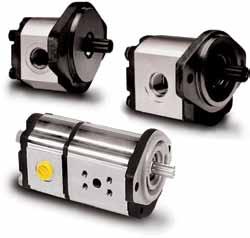
33 1/ Fixed Displacement Parker 600 Series Gear Pumps and Motors PGP Cast Iron Specifications 600 Series Cast Iron Features Patented interlocking body design 12 tooth gears, bronze balance plates Tandem, triple and cross-frame pumps available Common inlets available for tandem and triple pumps Continuous operating pressures up to 310 bar Production run-in available to suite OEM application conditions and to provide optimized volumetric efficiencies Pressure balanced design for high efficiency Reduced system noise levels compared to earlier models High power through-drive capability Wide range of integral valves for power steering, power brakes, fan drivers and implement hydraulics Load sense and solenoid operated unloading PGP/PGM620 Specification Pump Displacement Max. Continuous Press. PGP 620 Max. Continuous Press. PGP 625 Minimum Max. outlet press. Maximum 0 Inlet & Max. outlet press cm³/rev bar bar * * * * rpm rpm PGP/PGM640 Specification Pump Displacement Max. Continuous Pressure Minimum Max. outlet press. Maximum 0 Inlet & Max. outlet press cm³/rev bar 30, , , , , , , , , , , , ,0 180 rpm rpm
34 1/ Fixed Displacement Parker 600 Series Gear Pumps and Motors Preferred Model (Single Pump) Order Model cc/rev Shaft Mounting Seal Port (Inlet) Port (Outlet) Rotation PGP CD1H3NE6E T, SE"" spline SE"" 2 bolts NR 1-11 SP 3/4-16 SP CW PGP CD1H2NJ7J T, SE"" spline SE"" 2 bolts NR Ø20mm Square Ø15mm Square CW PGP CD1H2NT3T T, SE"" spline SE"" 2 bolts NR 25.4 mm Metric SF 19.0 mm Metric SF CW PGP CD13VT3T T, SE"" spline SE"" 4 bolts FPM 25.4 mm Metric SF 19.0 mm Metric SF CW PGP D1H3NT3T T, SE"" spline SE"" 4 bolts NR 25.4 mm Metric SF 19.0 mm Metric SF CCW PGP CD1H3N11E6E T, SE"" spline SE"" 2 bolts NR 1-11 SP (rear) 3/4-16 SP (rear) CW PGP CD1H3NE6E T, SE"" spline SE"" 2 bolts NR 1-11 SP 3/4-16 SP CW PGP D1H3N11E6E T, SE"" spline SE"" 2 bolts NR 1-11 SP (rear) 3/4-16 SP (rear) CCW PGP CD1H3NE6E T, SE"" spline SE"" 2 bolts NR 1-11 SP 3/4-16 SP CW PGP D1H3NE6E T, SE"" spline SE"" 2 bolts NR 1-11 SP 3/4-16 SP CCW PGP D1H3VT3T T, SE"" spline SE"" 2 bolts FPM 25.4 mm Metric SF 19.0 mm Metric SF CW PGP CD1H3NE6E T, SE"" spline SE"" 2 bolts NR 1-11 SP 3/4-16 SP CW PGP D1H3VT4T T, SE"" spline SE"" 2 bolts FPM 31.8 mm Metric SF 25.4 mm Metric SF CCW PGP D1H3NT4T T, SE"" spline SE"" 2 bolts NR 31.8 mm Metric SF 19.0 mm Metric SF CCW PGP CD1H3NE6E T, SE"" spline SE"" 2 bolts NR 1-11 SP 3/4-16 SP CW PGP D1H3VT4T T, SE"" spline SE"" 2 bolts FPM 31.8 mm Metric SF 25.4 mm Metric SF CCW PGP CD1H3VT4T T, SE"" spline SE"" 2 bolts FPM 31.8 mm Metric SF 25.4 mm Metric SF CW PGP CT1D7NE6E Ø21.59, Taper Key Ø50.77 Rectan NR 1-11 SP 3/4-16 SP CW PGP CD1H2N11E6E T, SE"" spline SE"" 2 bolts NR 1-11 SP (rear) 3/4-16 SP (rear) CW PGP CD1H3NE6E T, SE"" spline SE"" 2 bolts NR 1-11 SP 3/4-16 SP CW PGP D1H3NE6E T, SE"" spline SE"" 2 bolts NR 1-11 SP 3/4-16 SP CCW PGP CD1H3NT4T T, SE"" spline SE"" 2 bolts NR 31.8 mm Metric SF 25.4 mm Metric SF CW PGP CD1H2NE6E T, SE"" spline SE"" 2 bolts NR 1-11 SP 3/4-16 SP CW PGP CT1D7NE6E Ø21.59, Taper Key Ø50.77 Rectan NR 1-11 SP 3/4-16 SP CW PGP CD1H3VE7E T, SE"" spline SE"" 2 bolts FPM 1-1/4-11 SP 3/4-16 SP CW PGP CT1D7NE7E Ø21.59, Taper Key Ø50.77 Rectan NR 1-1/4-11 SP 3/4-16 SP CW PGP CM3H3NE6E Ø25.4, SE"-" Key SE"" 2 bolts NR 1-11 SP 3/4-16 SP CW PGP D1H3NT4T T, SE"" spline SE"" 2 bolts NR 31.8 mm Metric SF 25.4 mm Metric SF CCW PGP CD1H3ND6D T, SE"" spline SE"" 2 bolts NR 1 5/16-12 UNF 1 1/16-12 UNF CW PGP CT1D7N11E6E5 33 Ø21.59, Taper Key Ø50.77 Rectan NR 1-11 SP (rear) 3/4-16 SP (rear) CW PGP CD1H3NT4T T, SE"" spline SE"" 2 bolts NR 31.8 mm Metric SF 25.4 mm Metric SF CW PGP CD1H3NE7E T, SE"" spline SE"" 2 bolts NR 1-1/4-11 SP 3/4-16 SP CW PGP D1H3NE6E T, SE"" spline SE"" 2 bolts NR 1-11 SP 3/4-16 SP CCW PGP CD1H3NE8E T, SE"" spline SE"" 2 bolts NR 1-1/2-11 SP 1-11 SP CW PGP CD1H3NE6E T, SE"" spline SE"" 2 bolts NR 1-11 SP 3/4-16 SP CW PGP CD1H3ND8D T, SE"" spline SE"" 2 bolts NR 1 7/8-12 UNF 1 1/16-12 UNF CW PGP D1H3NE7E T, SE"" spline SE"" 2 bolts NR 1-1/4-11 SP 3/4-16 SP CCW PGP CD1H3NE7E T, SE"" spline SE"" 2 bolts NR 1-1/4-11 SP 3/4-16 SP CW PGP CD1H3NE6E T, SE"" spline SE"" 2 bolts NR 1-11 SP 3/4-16 SP CW PGP D1H3VT5T T, SE"" spline SE"" 2 bolts FPM 38.1 mm Metric SF 25.4 mm Metric SF CCW PGP CD1H3WS4S T, SE"" spline SE"" 2 bolts DFPM 1-1/4" SE SF 1" SE SF CW PGP CD1H3NE7E T, SE"" spline SE"" 2 bolts NR 1-1/4-11 SP 3/4-16 SP CW PGP CD1H2NE8E T, SE"" spline SE"" 2 bolts NR 1-1/2-11 SP 1-11 SP CW PGP CE1H3NT5T T, SE"-" spline SE"" 2 bolts NR 38.1 mm Metric SF 25.4 mm Metric SF CW PGP CD1H3NS5D T, SE"" spline SE"" 2 bolts NR 1-1/2" SE SF 1 5/16-12 UNF CW PGP CD1H3NE7E T, SE"" spline SE"" 2 bolts NR 1-1/4-11 SP 1-11 SP CW PGP CT1D7NL3L Ø21.59, Taper Key Ø50.77 Rectan NR Ø27mm Diamond Ø19mm Diamond CW PGP CD1H3NE7E T, SE"" spline SE"" 2 bolts NR 1-1/4-11 SP 3/4-16 SP CW PGP CD1H3VT5T T, SE"" spline SE"" 2 bolts FPM 38.1 mm Metric SF 25.4 mm Metric SF CW PGP CD1H3NE7E T, SE"" spline SE"" 2 bolts NR 1-1/4-11 SP 3/4-16 SP CW PGP D1H3NE7E T, SE"" spline SE"" 2 bolts NR 1-1/4-11 SP 3/4-16 SP CCW PGP D1H3NE8E T, SE"" spline SE"" 2 bolts NR 1-1/2-11 SP 1-11 SP CCW 34
35 1/ Fixed Displacement Parker 600 Series Gear Pumps and Motors Preferred Model (Single Motor) Order Model cc/rev Shaft Mounting Seal Port (Inlet) Port (Outlet) Rotation Drain PGM D1H3VE5E5 11G PGM D1H3HE5E5 11G PGM D1H3HE5E5 11G PGM T1D7NE5E5 11G PGM T1D7VE7E7 11G PGM D1H3HE5E5 11G PGM T1L3NL2L2 11G PGM D1H3HE5E5 11G PGM D1L3VE6E6 11G T, SE"" spline 13T, SE"" spline 13T, SE"" spline Ø21.59, Taper Key Ø21.59, Taper Key 13T, SE"" spline Ø21.59, Taper Key 13T, SE"" spline 13T, SE"" spline SE"" 2 bolts SE"" 2 bolts SE"" 2 bolts Ø50.77 Rectan Ø50.77 Rectan SE"" 2 bolts SE"" 2/4 bolts SE"" 2 bolts SE"" 2/4 bolts FPM NR NR NR FPM NR NR NR FPM 3/4-16 SP 3/4-16 SP 3/4-16 SP 3/4-16 SP 1-1/4-11 SP 3/4-16 SP Ø19 mm Diamond 3/4-16 SP 1-11 SP 3/4-16 SP 3/4-16 SP 3/4-16 SP 3/4-16 SP 1-1/4-11 SP 3/4-16 SP Ø19 mm Diamond 3/4-16 SP 1-11 SP I I I I I I I I I Rear, 1/4 SP Rear, 1/4 SP Rear, 1/4 SP Rear, 1/4 SP Rear, 1/4 SP Rear, 1/4 SP Rear, 1/4 SP Rear, 1/4 SP Rear, 1/4 SP 134 across body Dim N Y ±0.5 (see catalogue) Dim N X ±0.5 (see catalogue) 50.8 max max
36 1/ Fixed Displacement Parker 600 Series Gear Pumps and Motors Preferred Model (Tandum Pump) Mounting Seal Port (Inlet) Port (Outlet) Rotation 13T, SE"" Spline SE"" 2 bolts NR See ordering code See ordering code CW 13T, SE"" Spline SE"" 2 bolts DFPM See ordering code See ordering code CCW 13T, SE"" Spline SE"" 2 bolts FPM See ordering code See ordering code CW 15T, SE"-" Spline SE"" 2 bolts NR See ordering code See ordering code CCW 13T, SE"" Spline SE"" 2 bolts NR See ordering code See ordering code CW 13T, SE"" Spline SE"" 2 bolts NR See ordering code See ordering code CCW 15T, SE"-" Spline SE"C" 4 bolts DNR See ordering code See ordering code CW 13T, SE"" Spline SE"" 2 bolts NR See ordering code See ordering code CW 13T, SE"" Spline SE"" 2 bolts NR See ordering code See ordering code CW 13T, SE"" Spline SE"" 2 bolts DNR See ordering code See ordering code CW 134 across body Dim N Y1 Dim N X ±0.5 (see catalog) Dim N Y2 max. (see catalog) 41 ± max Shaft 50.8 max cc/rev Model PGP CD1H3NT4T3C X1T311 PGP CD1H3WT3T2S XT3T211 PGP CD1H3VT4T3S XT4T311 PGP E1H3NT4T3S XT4T311 PGP CD1H3NE6E5S NE5E311 PGP D1H3NT4T3S XT3T211 PGP CE14MT5T2C X1T211 PGP CD1H3NS4S2S XS4S311 PGP CD1H2NE7E5S XE7E511 PGP CD1H2MS4E6S XE5E Order 36
37 1/ Fixed Displacement Parker 600 Series Ordering code Gear Pumps and Motors Heavy-duty cast-iron Pumps and Motors Series PGP, PGM 620 PG 620 1) Gear Design Type Unit Displacement Rotation Shaft Flange Shaft Seal Side Suction Port Side Pressure Port Rear Suction Port 2) Rear Pressure Port 2) P M Type Pump Motor Unit Pump Motor Single unit Standard Motor without checks Multiple unit Standard Motor with two checks C Standard Motor w. one anti cavitation check (CC) Displacement ccm * 36* * 41* ** 45** 0500* 50* * PGP, PGM 620 and PGP 625 **PGP 625 only C Rotation Clockwise Counter clockwise bi-directional X N V M W Shaft Seal No seal NR FPM, FKM Double NR Double FPM Shaft D1 13T, 16/32DP, 41.2L, SE "" spline E1 15T, 16/32DP, 46L, SE "-" spline M3 Ø25.4, 6.3 Key, M8, 46L, SE "-", parallel T1 Ø21.59, 11.2L, 4.0 Key, M14x1.5, taper 1:8 T2 5) Ø25.0, 12L, 5.0 Key, M16x1.5, taper 1:5 5) Non standard, on request only Not all variances of ordering codes can be offered. Please check available part numbers first. For not yet implemented part numbers or special requests please contact Parker Hannifin. 1) vailable as PGP 625 with 36, 41, 45 and 50 cc/rev only. 2) Only coded for the last section. 3) Only for motors 37
38 1/ Fixed Displacement Parker 600 Series Ordering code 620 1) Gear Pumps and Motors Heavy-duty cast-iron Pumps and Motors Series PGP, PGM 620 4) Motor Drain Option 3) Drain Position 3) Section Connection Unit Displacement Shaft Seal Side Suction Port Side Pressure Port Rear Suction Port 2) Rear Pressure Port 2) S C Section Connection Separate inlets Common inlets Drain Position 2 5) Drain on bottom 3 5) Drain on top 4 Rear drain 5) Non standard, on request only 1 C G Motor Drain Option no drain 9/16-18 UNF thread 1/4 SP thread Flange x Ø101.6, SE "" 4 bolt square x Ø127, SE "C" 4 bolt square D7 98.4x Ø50.77 rectangular H Ø82.55 SE "" 2 bolt flange H Ø101.6 SE "" 2 bolt flange L3 89.8x SE 2/4 bolt flange Port Options 1 No ports D3 5) 3/4-16 UNF thread D4 5) 7/8-14 UNF thread D5 5) 1 1/16-12 UN thread D6 5) * 1 5/16-12 UN thread D7 5) * 1 5/8-12 UN thread D8 5) * 1 7/8-12 UN thread E3 1/2-14 SP thread E4 5/8-14 SP thread E5 3/4-16 SP thread E6* 1-11 SP thread E7* 1 1/4-11 SP thread E8* 1 1/2-11 SP thread J5* 15 mm - Ø35 mm - M6 square J7* 20 mm - Ø40 mm - M6 square J8* 18 mm - Ø55 mm - M8 square J9* 26 mm - Ø55 mm - M8 square L1* 13 mm-ø30 mm-m6 diamond L2* 19 mm-ø40 mm-m8 diamond L3* 27 mm-ø51 mm-m10 diamond Port Options S2 5) * 3/4"-3/8-16 UNC SE Split Flange S3 5) * 1"-3/8-16 UNC SE Split Flange S4 5) * 1 1/4"-7/16-14 UNC SE Split Flange S5 5) * 1 1/2"-1/2-13 UNC SE Split Flange S6 5) * 2"-1/2-13 UNC SE Split Flange T2* 19.0 mm - M10 Metric Split Flange T3* 25.4 mm - M10 Metric Split Flange T4* 31.8 mm - M10 Metric Split Flange T5* 38.1 mm - M12 Metric Split Flange T6* 50.8 mm - M12 Metric Split Flange 5) Non standard, on request only *) Not usable for rear ports 4) For further "" triple unit repeat displacement, shaft seal between sections, side suction port, side pressure port, rear suction port, rear pressure port. 38
39 1/ Fixed Displacement Parker 600 Series Gear Pumps and Motors PGP640 Preferred Model (Single Pump) Order Model cc/rev Shaft Mounting Seal PGP CE4K3NE8E T, SE"C" spline SE"C" 2 bolts NR PGP CE1H3NE8E T, SE"-" spline SE"" 2 bolts NR PGP CD1H3NT4T T. SE"" spline SE"" 2 bolts NR PGP CD1H3NT5T T. SE"" spline SE"" 2 bolts NR PGP CE44WT4T T, SE"C" spline SE"C" 4 bolts NR PGP D1H3NT4T T. SE"" spline SE"" 2 bolts NR PGP E44NS5S T, SE"C" spline SE"C" 4 bolts NR PGP CE44NT5T T, SE"C" spline SE"C" 4 bolts NR PGP E44NT5T T, SE"C" spline SE"C" 4 bolts NR PGP CD1H3NT4T T. SE"" spline SE"" 2 bolts NR PGP CD1H3NT5T T. SE"" spline SE"" 2 bolts NR PGP E44NS5S T, SE"C" spline SE"C" 4 bolts NR PGP D1H3NT5T T. SE"" spline SE"" 2 bolts NR PGP E1H3NT5T T, SE"-" spline SE"" 2 bolts NR PGP CD1H3NT5T T. SE"" spline SE"" 2 bolts NR PGP CD1H3NT5T T. SE"" spline SE"" 2 bolts NR PGP CE4K3NT6T T, SE"C" spline SE"C" 2 bolts NR PGP CE1H3VT6T T, SE"-" spline SE"" 2 bolts FPM PGP E4K3NS6S T, SE"C" spline SE"C" 2 bolts NR PGP CE44NT6T T, SE"C" spline SE"C" 4 bolts NR PGP CE44NT6T T, SE"C" spline SE"C" 4 bolts NR PGP E4K3NS6S T, SE"C" spline SE"C" 2 bolts NR Port (Inlet) 1-1/2-11 SP 1-1/2-11 SP 31.8 mm Metric SF 38.1mm Metric SF 31.8 mm Metric SF 31.8 mm Metric SF 1-1/2" SE SF 38.1mm Metric SF 38.1mm Metric SF 31.8 mm Metric SF 38.1mm Metric SF 1-1/2" SE SF 38.1mm Metric SF 38.1mm Metric SF 38.1mm Metric SF 38.1mm Metric SF 50.8mm Metric SF 50.8mm Metric SF 2" SE SF 50.8mm Metric SF 50.8mm Metric SF 2" SE SF DIM. "Y" (see catalogue) DIM. "X" (see catalogue) across body 39

40 1/ Fixed Displacement Parker 600 Series Gear Pumps and Motors Preferred Model (Single Motor) Order Model cc/rev Shaft Mounting Seal Port (Inlet) PGM D13TE7E T, SE"" spline SE"" 4 bolts PTFE 1-1/4-11 SP PGM E4K3TT3T3 11G T, SE"C" spline SE"C" 2 bolts PTFE 25.4mm Metric SF PGM E44TT4T T, SE"C" spline SE"C" 4 bolts PTFE 31.8 mm Metric SF PGM CE13TT4T 411G T, SE"-" spline SE"" 4 bolts PTFE 31.8 mm Metric SF PGM E4K3TT3T3 11G T, SE"C" spline SE"C" 2 bolts PTFE 25.4mm Metric SF PGM E44TT4T T, SE"C" spline SE"C" 4 bolts PTFE 31.8 mm Metric SF Preferred Model (Tandum Pump) Order Model cc/rev Shaft Mounting Seal Port (Inlet) Port (Outlet) Rotation PGP CD1H3NT5T3S XE5E311 PGP CE44NE8E7S XE8E711 PGP D1H3NT5T3S XJ7J5S XJ7J511 PGP E44MT6T3C X1T311 PGP CD1H3NS5S3C XE5E511 PGP CD1H3NS5S4C X1E311 PGP E14NT4T3C XE6E6S XE611 PGP E44NS6S4C X1S T, SE"" Spline SE"" 2 bolts NR See ordering code See ordering code CW 14T, SE"C" Spline SE"C" 4 bolts NR See ordering code See ordering code CW 13T, SE"" Spline SE"" 2 bolts NR See ordering code See ordering code CCW 14T, SE"C" Spline SE"C" 4 bolts NR See ordering code See ordering code CCW 13T, SE"" Spline SE"" 2 bolts NR See ordering code See ordering code CW 13T, SE"" Spline SE"" 2 bolts NR See ordering code See ordering code CW 15T, SE"-" Spline SE"C" 4 bolts NR See ordering code See ordering code CW 14T, SE"C" Spline SE"C" 4 bolts NR See ordering code See ordering code CCW DIM. "Y1" (see catalogue) DIM. "X1" (see catalogue) DIM. "Y2" (see catalogue) DIM. "X2" (see catalogue) across body 40
41 1/ Fixed Displacement Parker 600 Series Ordering PG 640 Gear Pumps and Motors Heavy-duty cast-iron Pumps and Motors Series PGP, PGM 640 P M Type Pump Motor Gear design Type Unit Displacement Rotation Shaft Flange Shaft seal Side Suction Port Side Pressure Port Rear Suction Port 2) Rear Pressure Port 2) Unit Pump Motor Single unit Standard Motor without checks Multiple unit Standard Motor with two checks C Standard Motor w. one anti cavitation check (CC) Displacement ccm * *) Non standard, on request only C Rotation Clockwise Counter clockwise i-directional X N V T Shaft Seal No seal NR FPM PTFE (motors only) D1 E1 E4 N1 Shaft 13T, 16/32DP, 41.2L, SE spline 15T, 16/32DP, 46.0L, SE - spline 14T, 12/24DP, 55.6L, SE C spline 1 1/4" Keyed SE-C Flange x Ø101.06, SE "" 4 bolt square flange x Ø127, SE "C" 4 bolt square flange H Ø SE "" 2 bolt flange K Ø127 SE C 2 bolt flange Not all variances of ordering codes can be offered. Please check available part numbers first. For not yet implemented part numbers or special requests please contact Parker Hannifin. 2) Only coded for the last section. 3) Only for motors 41
42 1/ Fixed Displacement Parker 600 Series Ordering code Gear Pumps and Motors Heavy-duty cast-iron Pumps and Motors Series PGP, PGM ) No rear ports (rear ports on request) Motor Drain Option 3) Drain Position 3) Section Connection Unit Displacement Shaft Seal Side Suction Port Side Pressure Port Rear Rear Pressure Port 2) Suction Port 2) S C Section Connection Separate inlets Common inlets Drain Position 2 Drain on bottom 3 Drain on top 4 Rear drain 1 C G Motor Drain Option no drain 9/16-18 UNF thread 1/4 SP thread Port Options 1 No ports D5 5) 1 1/16-12 UN thread D6 5) * 1 5/16-12 UN thread D7 5) * 1 5/8-12 UN thread D8 5) * 1 7/8-12 UN thread E4 5/8-14 SP thread E5 3/4-16 SP thread E6* 1-11 SP thread E7* 1 1/4-11 SP thread E8* 1 1/2-11 SP thread J8* 18 mm - Ø55 mm - M8 square J9* 26 mm - Ø55 mm - M8 square L2* 19 mm-ø40 mm-m8 diamond L3* 27 mm-ø51 mm-m10 diamond Port Options S2 5) * 3/4"-3/8-16 UNC SE Split Flange S3 5) * 1"-3/8-16 UNC SE Split Flange S4 5) * 1 1/4"-7/16-14 UNC SE Split Flange S5 5) * 1 1/2"-1/2-13 UNC SE Split Flange S6 5) * 2"-1/2-13 UNC SE Split Flange T2* 19.0 mm - M10 Metric Split Flange T3* 25.4 mm - M10 Metric Split Flange T4* 31.8 mm - M10 Metric Split Flange T5* 38.1 mm - M12 Metric Split Flange T6* 50.8 mm - M12 Metric Split Flange 5) Non standard, on request only *) Not usable for rear ports 4) For further "" triple unit repeat displacement, shaft seal between sections, side suction port, side pressure port, rear suction port, rear pressure port. 42


43 1/ Fixed Displacement pplication Market Gear Pumps and Motors Market gricultural Industrial Construction Material Handling Mining & Drilling Mover, Haypresses, Forwarder, Shredder Hydraulic Power Units Loader ackhoe, Wheel Loader, Telehandler Forklift, Reachstacker, Crane Drill Rig, Loader, Dump Truck pplications 43


44 1/ Fixed Displacement Literature Gear Pumps and Motors Ref: Catalog HY /US (PGP/M 315, 330, 350, 365) Ref: Catalogue HY /UK (PGP/M 511, 517, 620, 640) 44


45 Vane Pumps 1/ Fixed Displacement

46 1 1/ Fixed Displacement SDV Series Characteristics The SDV fixed displacement vane pump range offers a quiet efficient solution in many lower and medium pressure applications. Numerous shaft options and porting combinations result in easier installations. Single and double pump combinations, 7 displacements in each series. Vane Pumps Category Features SDV 10 and SDV 20 Series Displacements 3.3 cc/rev cc/rev Speed range to 4200 RPM Pressure to 175 ar Quiet Operation Various shaft and mount options Single and double pump options Series SDV10 SDV20 Size Displacement Max speed (cc/rev) (rpm) Int (bar) Cont (bar) SDV2010 s bove s selected SDV2020 s bove s selected Lower limit of selected sizes. Lower limit of selected sizes. Max Pressure Operation of selected size Operation of selected size Mounting SE SE SE 2-bolt SE 2-bolt Shafts 3/4" key 5/8" 9T Spl 3/4" 11T Spl 3/4" key 5/8" 9T Spl 3/4" 11T Spl 7/8" key 7/8" 13T Spl 7/8" key 7/8" 13T Spl 46
47 1/ Fixed Displacement SDV Series SDV10, SDV20 Series Vane Pumps Category 1 SDV Series 10 SDV10 20 SDV20 L Rotation Counter-Clockwise Omit For Clockwise Mounting 1 SE '' 2 olt S P Inlet Port SDV10 SDV20 1 5/16"-12 SE 1 5/8"-12 SE Straight Thread Straight Thread 1" NPTF Thread 1" SPP Thread Displacement SDV cc/rev cc/rev cc/rev cc/rev cc/rev cc/rev cc/rev SDV cc/rev cc/rev cc/rev cc/rev cc/rev cc/rev cc/rev 1" NPTF Thread 1" SPP Thread 1 C D SDV10 3/4" Parallel Keypad 11 5/8" 9T Spline Shaft 38 3/4" 11T Spline Shaft (Short) Outlet Port Location (Viewed from cover end) Opposite Inlet Port 90º CCW from Inlet In Line with Inlet 90º CW from Inlet Shaft SDV20 3/4" Parallel Keypad 3/4" 11T Spline Shaft (Long) 3/4" 11T Spline Shaft (Short) 62 5/8" 9T Spline Shaft S P SDV10 3/4"-16 SE Straight Thread 1/2"-NPTF Ou Thread 1/2"-SPP Ou Thread Outlet Port SDV20 3/4"-16 SE Straight Thread 1/2"-NPTF Thread 1/2"-SPP Thread 47
48 1 1/ Fixed Displacement SDV Series SDV2010, SDV2020 Series Vane Pumps SDV Series 2010 SDV SDV2020 L Rotation Omit for Clockwise Counter-Clockwise Mounting 1 SE '' 2 olt F S Inlet Port 1-1/2" SE 61 (2010) 2" SE 61 (2020) Displacement (Shaft/Cover End) SDV cc/rev cc/rev cc/rev cc/rev cc/rev cc/rev cc/rev SDV cc/rev cc/rev cc/rev cc/rev cc/rev cc/rev cc/rev Outlet Port (Shaft End) Straight Thread Outlet Port (Cover End) SDV2010 Outlet Port (Shaft End) 3/4" SPP Thread Outlet Port (Cover End) SDV2010 Position of Outlet Port (Viewed from cover end) SDV2010 #2 Oulet 135' CCW From Inlet #2 Outlet 45' CCW From Inlet C #2 Outlet 45' CW From Inlet D #2 Outlet 135' CW From Inlet Double Pump With #1 Outlet 90º CCW From Inlet #2 Outlet 135' CCW From Inlet #2 Outlet 45' CCW From Inlet C #2 Outlet 45' CW From Inlet D #2 Outlet 135' CW From Inlet Double Pump With #1 Outlet in Line With Inlet C #2 Outlet 135' CCW From Inlet C #2 Outlet 45' CCW From Inlet CC #2 Outlet 45' CW From Inlet CD #2 Outlet 135' CW From Inlet Double Pump With #1 Outlet 90º CW From Inlet D #2 Outlet 135' CCW From Inlet D #2 Outlet 45' CCW From Inlet DC #2 Outlet 45' CW From Inlet DD #2 Outlet 135' CW From Inlet Position of Outlet Port (Viewed from cover end) SDV2020 #2 Oulet opposite From Inlet #2 Outlet 90' CCW From Inlet C #2 Outlet in line with Inlet D #2 Outlet 90' CW From Inlet Double Pump With #1 Outlet 90º CCW From Inlet #2 Outlet opposite From Inlet #2 Outlet 90' CCW From Inlet C #2 Outlet in line with Inlet D #2 Outlet 90' CW From Inlet Double Pump With #1 Outlet in Line With Inlet C #2 Outlet opposite From Inlet C #2 Outlet 90' CCW From Inlet CC #2 Outlet in line with Inlet CD #2 Outlet 90' CW From Inlet Double Pump With #1 Outlet 90º CW From Inlet D #2 Outlet opposite From Inlet D #2 Outlet 90' CCW From Inlet DC #2 Outlet in line with Inlet DD #2 Outlet 90' CW From Inlet S 3/4"-16 Straight Thread SDV2020 1/2" SPP Thread SDV Shaft End 7/8" Parallel Keyed S Straight Thread 3/4" SPP Thread 11 7/8" 13T Spline 48

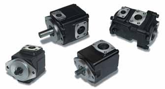
49 1/ Fixed Displacement Single Pumps Vane Pumps 1 T7, T6C, T7D, T7E Series Characteristics The Parker 'Denison' fixed displacement vane pump range offers a quieter more efficient solution to many high pressure applications. Designed with versatility in mind, numerous shaft options and porting combinations result in easier installation. The pumps will operate over a wide speed range with low to high viscosity fluids; and technical advantages in vane design offer high resistance to particle contamination. Interchangeable cam rings allow multiple displacements within the same pump frame size. n industrial or mobile type cartridge allows the pump to operate to its optimum in many environments. The cartridge concept simplifies pump maintenance reducing machine down time. Features 5 frame sizes,, C, D, E Displacement 5.8cc/rev 268cc/rev Speed to 3600 RPM Pressure to 320 ar Quiet operation Various shaft and mount options Cartridge design Wide range of acceptable viscosity Example Model Displacement (cc/rev) Max Pressure (ar) Speed (RPM) no. of cam ring displacements ( ) Cont / Int Min/ Max (9) 290 / / 3600 T (3) 275 / / / / / / 2800 T6C / / (2) 160 / / (7) 250 / / (2) 250 / / 2800 T7D / / * 210 / / * 160 / / 2200 T7E (9) 210 / / / / 2000 Data for HF-0, HF-2 for comparisons only * Ten vane technology Greater Flow Size : 5,8 to 40 cc/rev Size : 5,8 to 50 cc/rev Size C : 10,8 to 100 cc/rev Size D : 44 to 158 cc/rev Size E : 132,3 to 268,7 cc/rev Higher Pressure Size : up to 300 bar max Size : up to 320 bar max (300 bar for multiple pump) Size C : up to 275 bar max Size D : up to 280 bar max (250 bar for multiple pump) Size E : up to 240 bar max 49
50 1/ Fixed Displacement Single Pumps Vane Pumps Single pumps : speeds, pressure ratings Model of pump T6C T7D T7DS T7E 2) T7ES Series Theoretical Displacement Vi , , , , , , , , , , , , , , , , , , , , , ,6 Int. Cont. Int. Cont. Int. Cont. ml/rev. RPM RPM RPM bar bar bar bar bar bar , ) 145, ) 158, , , , , , , , , ,1 Minimum Speed Maximum Speed 3) HF-0, HF-1 HF HF-3, HF-4 HF HF-0, HF , Maximum Pressure HF-1, HF-4, HF HF ) Ten vane technology. 2) For T7E, below 10 bar, please contact Parker. 3) Please be sure that the inlet velocity is under 1,9 m/sec. (see page 12, start-up & check-up). For further information, or if the performance characteristics outlined here above do not meet your particular requirements, please consult your local Parker office. HF-0, HF-2 = ntiwear Petroleum ase HF-1 = Non ntiwear Petroleum ase HF-3 = Water in oil Invert Emulsions HF-4 = Water Glycols Solutions HF-5 = Synthetic Fluids 50
51 1/ Fixed Displacement Single Pumps T6C Series Vane Pumps T6C* R ** Series SE 2 bolts J744 mounting flange * Rear drive option available, please contact Parker Displacement* Volumetric displacement (ml/rev.) 03 = 10,8 17 = 58,3 05 = 17,2 20 = 63,8 06 = 21,3 22 = 70,3 08 = 26,4 25 = 79,3 10 = 34,4 28 = 88,8 12 = 37,1 31 = 100,0 14 = 46,0 Type of Shaft Tbc 1 = keyed (SE ) ø 22,2 2 = keyed (non SE) 3 = splined (SE ) 13 teeth 4 = splined (SE ) 15 teeth P = Pressure port S = Suction port Modifications Seal Class 1 = S1 UN N 0.7 bar max. (for mineral oil) 4 = S4 EPDM 0.7 bar max. (for fire resistant fluids 5 = S5 VITON 0.7 bar max (for mineral oil and fire resistant fluid Design Letter Porting Combination 00 = Standard Direction of rotation (shaft end view) R = Clockwise L = Counter-clockwise P P S P P S S Preferred Model (Single Pump) Order Model Order Model Order Model T6C 03 1R** T6C 10 3R** T6C 20 4R** T6C 03 2R** T6C 10 4R** T6C 22 1R** T6C 03 3R** T6C 12 1R** T6C 22 3R** T6C 05 1R** T6C 12 3R** T6C 22 4R** T6C 05 3R** T6C 12 4R** T6C 25 1R** T6C 05 4R** T6C 14 1R** T6C 25 3R** T6C 06 1R** T6C 14 3R** T6C 25 4L** T6C 06 3R** T6C 14 4R** T6C 28 1R** T6C 06 4R** T6C 17 1R** T6C 28 3R** T6C 08 1R** T6C 17 3R** T6C 28 4R** T6C 08 3R** T6C 17 4R** T6C 31 1R** T6C 08 4R** T6C 20 1R** T6C 31 3R** T6C 10 1R** T6C 20 3R** T6C 31 4R** 1 For other Seal Class S4 EPDM 024-XXXXX-4 S5 VITON 024-XXXXX-5 For other Port Orientation 024-XXXXX-001, 024-XXXXX-002, 024-XXXXX-003, etc For Chinese Version 024-XXXXX-00S (to put "S" behind) 51
52 1/ Fixed Displacement Single Pumps T7DS Series T7DS* R ** Vane Pumps 1 T7DS Series - SE C 2 bolts J744 mounting flange Modifications * Rear drive option available, please contact Parker Displacement* Volumetric displacement (ml/rev.) 14 = 44,0 31 = 99,2 17 = 55,0 35 = 113,4 20 = 66,0 38 = 120,6 22 = 70,3 42 = 137,5 24 = 81,1 045 = 145,7 28 = 90,0 050 = 158,0 Mounting w/connection variables P = 1.1/4" S = 2" T7DS M0 Seal Class 1 = S1 UN N 0.7 bar max. ( for mineral oil) 4 = S4 EPDM 0.7 bar max. (for fire resistant fluids 5 = S5 VITON 0.7 bar max (for mineral oil and fire resistant fluids Type of Shaft T7DS Design Letter 1 = keyed (SE C) ø 31,7 Porting Combination 2 = keyed (non SE) 00 = Standard 3 = splined (SE C) 14 teeth 4 = splined (non SE) Direction of rotation (shaft end view) R = Clockwise P P S P P L - Counter-clockwise P = Pressure port S S = Suction port S Preferred Model (Single Pump) Order Model Order Model Order T7DS 14 1R** 1M T7DS 28 1R** 1M T7DS 14 3R** 1M T7DS 28 3R** 1M T7DS 17 1R** 1M T7DS 31 1R** 1M T7DS 17 3R** 1M T7DS 31 3R** 1M T7DS 20 1R** 1M T7DS 35 1R** 1M T7DS 20 3R** 1M T7DS 35 3R** 1M T7DS 22 1R** 1M T7DS 38 1R** 1M T7DS 22 3R** 1M T7DS 38 3R** 1M T7DS 24 1R** 1M T7DS 42 1R** 1M T7DS 24 3R** 1M T7DS 42 3R** 1M For other Seal Class S4 EPDM 024-XXXXX-4 S5 VITON 024-XXXXX-5 For other Port Orientation 024-XXXXX-001, 024-XXXXX-002, 024-XXXXX-003, etc For Chinese Version 024-XXXXX-00S (to put "S" behind) 52
53 1/ Fixed Displacement Single Pumps T7ES Series Vane Pumps T7ES* R ** T7ES Series - SE C 2 bolts J744 mounting flange * Rear drive option available, please contact Parker Displacement* Volumetric displacement (ml/rev.) 042 = 132,3 057 = 183,3 045 = 142,4 062 = 196,7 050 = 158,5 066 = 213,3 052 = 164,8 072 = 227,1 054 = 171,0 085 = 268,7 Type of Shaft T7ES 1 = keyed (SE CC) 2 = keyed (non SE) 3 = splined (SE C) 14 teeth 4 = splined (SE CC) 17 teeth Direction of rotation (shaft end view) R = Clockwise L = Counter-clockwise P P S P P Modifications Mounting w/connection variables 4 bolts SE flanges J518) T7ES Metric thread M0 P 1.1/2" S 3" Seal Class 1 = S1 UN N 0.7 bar max. (for mineral oil) 4 = S4 EPDM 0.7 bar max. (for fire resistant fluids 5 = S5 VITON 0.7 bar max (for mineral oil and fire resistant fluids S Design Letter Porting Combination 00 = Standard P = Pressure port S = Suction port S Preferred Model (Single Pump) Order Model Order Model Order T7ES 042 1R** 1M T7ES 052 1L** 1M T7ES 042 3R** 1M T7ES 052 3R** 1M T7ES 042 4R** T7ES 054 1R** 1M T7ES 045 1R** 1M T7ES 054 1L** 1M T7ES 045 3R** 1M T7ES 054 3R** 1M T7ES 045 4R** 1M T7ES 057 1R** 1M T7ES 050 1R** 1M T7ES 057 1L** 1M T7ES 050 3R** 1M T7ES 057 3R** 1M T7ES 050 4R** T7ES 062 1R** 1M T7ES 052 1R** 1M T7ES 062 3R** 1M For other Seal Class S4 EPDM 024-XXXXX-4 S5 VITON 024-XXXXX-5 For other Port Orientation 024-XXXXX-001, 024-XXXXX-002, 024-XXXXX-003, etc For Chinese Version 024-XXXXX-00S (to put "S" behind) 53

54 1/ Fixed Displacement Double Pumps Vane Pumps 1 T7, T67C, T6CC, T7DS, T67DC, T7ES, T67EC, T7EDS, T7EES Series Characteristics The Parker 'Denison' fixed displacement vane pump range offers a quieter more efficient solution to many high pressure applications. Designed with versatility in mind, numerous shaft options and porting combinations result in easier installation. The pumps will operate over a wide speed range with low to high viscosity fluids; and technical advantages in vane design offer high resistance to particle contamination. Interchangeable cam rings allow multiple displacements within the same pump frame size. n industrial or mobile type cartridge allows the pump to operate to its optimum in many environments. The cartridge concept simplifies pump maintenance reducing machine down time. Multiple cartridges in single housing with common suction minimise installation costs. Flow combinations for Hi-Low or multi-flow systems. Features 5 frame sizes,, C, D, E Many combinations of frame sizes Displacement 5.8cc/rev 268cc/rev Speed to 3600 RPM Pressure to 320 ar Quiet operation Various shaft and mount options Cartridge design Wide range of acceptable viscosity Severe duty options available Example Model T7 T6CC T7DD T7EE Displacement (cc/rev) Max Pressure (ar) Speed (RPM) no. of cam ring displacements ( ) Cont / Int Min/ Max (9) 290 / / (3) 275 / / / / / / / / (2) 160 / / (7) 250 / / (2) 250 / / / / * 210 / / * 160 / / (9) 210 / / / / 2000 Data for HF-0, HF-2 for comparisons only * Ten vane technology 54
55 1/ Fixed Displacement Double Pumps Vane Pumps T7S Series T7S R ** 1 T7S Series - SE 2 bolts J744 mounting flange Displacement P1 & P2 Volumetric displacement (ml/rev.) 02 = 5,8 09 = 28,0 03 = 9,8 10 = 31,8 04 = 12,8 11 = 35,0 05 = 15,9 12 = 41,0 06 = 19,8 14 = 45,0 07 = 22,5 15 = 50,0 08 = 24,9 Type of Shaft T7S 1 = keyed (non SE) 2 = keyed (SE ) 3 = splined (SE ) 13 teeth 4 = splined (SE ) 15 teeth Direction of rotation (shaft end view) R = Clockwise L = Counter-clockwise T6CC Series Modifications Mounting w/connection variables 4 bolts SE flanges J518) T7S UNC thread P1 1" 3/4" P2 3/4" S 2,1/2" Seal Class 1 = S1 UN N 0.7 bar max. (for mineral oil) 4 = S4 EPDM 0.7 bar max. (for fire resistant fluids 5 = S5 VITON 0.7 bar max (for mineral oil and fire resistant fluid Design Letter Porting Combination 00 = Standard T6CC W R 00 C ** T6CC Series - SE 2 bolts J744 mounting flange Severe duty shaft option Displacement P1 & P2 Volumetric displacement (ml/rev.) 02 = 10,8 17 = 58,3 05 = 17,2 20 = 63,8 06 = 21,3 22 = 70,3 08 = 26,4 25 = 79,3 10 = 34,1 28 = 88,8 12 = 37,1 31 = 100,0 14 = 46,0 Type of Shaft T6CC 1 = keyed (non SE) 3 = splined (SE ) 15 teeth 5 = splined (SE ) 13 teeth Direction of rotation (shaft end view) R = Clockwise L = Counter-clockwise Severe duty shaft (T6CCW only) 2 = keyed (SE ) Modifications Mounting w/connection variables P1 = 1" - S = 3" UNC thread P2 1" 3/4" 1 P1 = 1" - S = 2,1/2" 2 UNC thread P2 1" 3/4" 1 1) up to 46ml/rev. max. 2) up to 126ml/rev. max. lways select the largest cartridge in the front place. Seal Class 1 = S1 UN N 0.7 bar max. (for mineral oil) 4 = S4 EPDM 0.7 bar max. (for fi e resistant fluids 5 = S5 VITON 0.7 bar max (for mineral oil and fi e resistant fluids Design Letter Porting Combination 00 = Standard 55
56 1/ Fixed Displacement Double Pumps Vane Pumps 1 T67C T67C W R ** T67C Series - SE 2 bolts J744 mounting flange Severe duty shaft option Displacement P1 Volumetric displacement (ml/rev.) 02 = 10,8 17 = 58,3 05 = 17,2 20 = 63,8 06 = 21,3 22 = 70,3 08 = 26,4 25 = 79,3 10 = 34,1 28 = 88,8 12 = 37,1 31 = 100,0 14 = 46,0 Displacement P2 Volumetric displacement (ml/rev.) 02 = 5,8 09 = 28,0 03 = 9,8 10 = 31,8 04 = 12,8 11 = 35,0 05 = 15,9 12 = 41,0 06 = 19,8 14 = 45,0 07 = 22,5 15 = 50,0 08 = 24,9 T7DS Series Severe duty shaft (T67CW only) 2 = keyed (SE ) Type of Shaft 1 = keyed (non SE) 3 = splined (SE ) 15 teeth 5 = splined (SE ) 13 teeth Modification Mounting w/connection variables P1 = 1" - S = 3" UNC thread P2 1" 3/4" 1 P1 = 1" - S = 2,1/2" 2 UNC thread P2 1" 3/4" 1 1) up to 46ml/rev. max. 2) up to 126ml/rev. max. lways select the largest cartridge in the front place. Seal Class 1 = S1 UN N 0.7 bar max. (for mineral oil) 4 = S4 EPDM 0.7 bar max. (for fire resistant fluids) 5 = S5 VITON 0,7 bar max (for mineral oil and fire resistant fluid) Design Letter Porting Combination 00 = Standard Direction of rotation (shaft end view) R = Clockwise L = Counter-clockwise T7DS R ** T7DS Series - SE C 2 bolts J744 mounting flange Displacement P1 Volumetric displacement (ml/rev.) 14 = 44,0 31 = 99,2 17 = 55,0 35 = 113,4 20 = 66,0 38 = 120,6 22 = 70,3 42 = 137,5 24 = 81,1 045 = 145,7 28 = 90,0 050 = 158,0 Displacement P2 Volumetric displacement (ml/rev.) 02 = 5,8 09 = 28,0 03 = 9,8 10 = 31,8 04 = 12,8 11 = 35,0 05 = 15,9 12 = 41,0 06 = 19,8 14 = 45,0 07 = 22,5 15 = 50,0 08 = 24,9 Type of Shaft 1 = keyed (SE C) 2 = keyed (non SE) 3 = splined (SE C) 14 teeth 4 = splined (spec SE C) Direction of rotation (shaft end view) R = Clockwise L = Counter-clockwise Modifications Mounting w/connection variables 4 bolts SE flanges J518) UNC thread T7DS P1 1,1/4" 1,1/4" P2 1" 3/4" S 3" 3" Seal Class 1 = S1 UN N 0.7 bar max. (for mineral oil) 4 = S4 EPDM 0.7 bar max. (for fire resistant fluids) 5 = S5 VITON 0,7 bar max (for mineral oil and fire resistant fluids) Design Letter Porting Combination 00 = Standard 56
57 1/ Fixed Displacement Double Pumps T67DC Series T67DC W R ** Vane Pumps 1 T67DC Series - SE C 2 bolts J744 mounting flange Severe duty shaft option Displacement P1 Volumetric displacement (ml/rev.) 14 = 44,0 31 = 99,2 17 = 55,0 35 = 113,4 20 = 66,0 38 = 120,6 22 = 70,3 42 = 137,5 24 = 81,1 045 = 145,7 28 = 90,0 050 = 158,0 Displacement P2 Volumetric displacement (ml/rev.) 03 = 10,8 31 = 99,2 05 = 17,2 35 = 113,4 06 = 21,3 38 = 120,6 08 = 26,4 42 = 137,5 10 = 34,1 045 = 145,7 12 = 37,1 050 = 158,0 14 = 46,0 Type of Shaft 1 = keyed (SE C) 3 = splined (SE C) 14 teeth 2 = keyed (non SE) 4 = splined (spec SE C) Type of Shaft - Severe duty (T67DCW only) 5 = keyed (non SE) Modifications Mounting w/connection variables 4 bolts SE flanges J518) UNC thread T7DS P1 1,1/4" 1,1/4" P2 1" 3/4" S 3" 3" Seal Class 1 = S1 UN N 0.7 bar max. (for mineral oil) 4 = S4 EPDM 0.7 bar max. (for fire resistant fluids) 5 = S5 VITON 0,7 bar max (for mineral oil and fire resistant fluids) Design Letter Porting Combination 00 = Standard Direction of rotation (shaft end view) R = Clockwise L = Counter-clockwise T7DDS Series T7DDS R ** T7DDS Series - SE C 2+4 bolts J744 mounting flange Displacement P1 & P2 Volumetric displacement (ml/rev.) 14 = 44,0 31 = 99,2 17 = 55,0 35 = 113,4 20 = 66,0 38 = 120,6 22 = 70,3 42 = 137,5 24 = 81,1 045 = 145,7 28 = 90,0 050 = 158,0 Type of Shaft 1 = keyed (SE C) 3 = splined (SE C) 14 teeth 2 = keyed (non SECC) Direction of rotation (shaft end view) R = Clockwise L = Counter-clockwise Modifications Mounting w/connection variables 4 bolts SE flanges J518) P1 & P2 = 1.1/4" - S = 4" Type UNC Thread T7DDS 00 Seal Class 1 = S1 UN N 0.7 bar max. (for mineral oil) 4 = S4 EPDM 0.7 bar max. (for fire resistant fluids) 5 = S5 VITON 0,7 bar max (for mineral oil and fire resistant fluids) Design Letter Porting Combination 00 = Standard 57
58 1/ Fixed Displacement Double Pumps Vane Pumps 1 T7ES Series T7ES R ** T7ES Series - SE C 2 bolts J744 mounting flange Displacement P1 Volumetric displacement (ml/rev.) 042 = 132,3 057 = 183,3 045 = 142,4 062 = 196,7 050 = 158,5 066 = 213,3 052 = 164,8 072 = 227,1 054 = 171,0 085 = 268,7 Displacement P2 Volumetric displacement (ml/rev.) 02 = 5,8 09 = 28,0 03 = 9,8 10 = 31,8 04 = 12,8 11 = 35,0 05 = 15,9 12 = 41,0 06 = 19,8 14 = 45,0 07 = 22,5 15 = 50,0 08 = 24,9 P1 P2 Type of Shaft 1 = keyed (SECC) 3 = splined (SE C) 14 teeth 2 = keyed (non SE) 4 = splined (SECC) Modifications Mounting w/connection variables 4 bolts SE flanges J518) UNC thread T7ES 01 Seal Class 1 = S1 UN N 0,7 bar max. (for mineral oil) 4 = S4 EPDM 7 bar max. (for fire resistant fluids) 5 = S5 VITON 7 bar max (for mineral oil and fire resistant fluids) Design Letter Porting Combination 00 = Standard Direction of rotation (shaft end view) R = Clockwise L = Counter-clockwise T67EC Series T67EC R ** T67EC Series - SE C 2 bolts J744 mounting flange Displacement P1 Volumetric displacement (ml/rev.) 042 = 132,3 057 = 183,3 045 = 142,4 062 = 196,7 050 = 158,5 066 = 213,3 052 = 164,8 072 = 227,1 054 = 171,0 085 = 268,7 Displacement P2 Volumetric displacement (ml/rev.) 03 = 10,8 17 = 58,3 05 = 17,2 20 = 63,8 06 = 21,3 22 = 70,3 08 = 26,4 25 = 79,3 10 = 34,1 28 = 88,8 12 = 37,1 31 = 100,0 14 = 46,0 Type of Shaft 1 = keyed (SECC) 3 = splined (SE C) 14 teeth 2 = keyed (non SE) 4 = splined (SECC) 17 teeth Modifications Mounting w/connection variables 4 bolts SE flanges J518) UNC thread P1 1,1/2" 1,1/2" P2 1" 3/4" S 3,1/2" 3,1/2" Seal Class 1 = S1 UN N 0,7 bar max. (for mineral oil) 4 = S4 EPDM 7 bar max. (for fire resistant fluids) 5 = S5 VITON 7 bar max (for mineral oil and fire resistant fluids) Design Letter Porting Combination 00 = Standard Direction of rotation (shaft end view) R = Clockwise L = Counter-clockwise 58
59 1/ Fixed Displacement Double Pumps T7EDS Series T7EDS R ** Vane Pumps 1 T7EDS Series - SE C 2 bolts J744 mounting flange Displacement P1 Volumetric displacement (ml/rev.) 042 = 132,3 057 = 183,3 045 = 142,4 062 = 196,7 050 = 158,5 066 = 213,3 052 = 164,8 072 = 227,1 054 = 171,0 085 = 268,7 Displacement P2 Volumetric displacement (ml/rev.) 14 = 44,0 31 = 99,2 17 = 55,0 35 = 113,4 20 = 66,0 38 = 120,6 22 = 70,3 42 = 137,5 24 = 81,1 045 = 145,7 28 = 81,1 050 = 158,0 Type of Shaft 1 = keyed (SE CC) 3 = splined (SE C) 14 teeth 2 = keyed (non SE) 4 = splined (SE CC) 17 teeth Modifications Mounting w/connection variables 4 bolts SE flanges J518) 7EDS Type UNC thread 00 Seal Class 1 = S1 UN N 0,7 bar max. (for mineral oil) 4 = S4 EPDM 7 bar max. (for fire resistant fluids) 5 = S5 VITON 7 bar max (for mineral oil and fire resistant fluids) Design Letter Porting Combination 00 = Standard Direction of rotation (shaft end view) R = Clockwise L - Counter-clockwise T7EES Series T7EES R ** T7EES Series - SE E 4 bolts J744 mounting flang Displacement P1 & P2 Volumetric displacement (ml/rev.) 042 = 132,3 057 = 183,3 045 = 142,4 062 = 196,7 050 = 158,5 066 = 213,3 052 = 164,8 072 = 227,1 054 = 171,0 085 = 268,7 Type of Shaft 1 = keyed (SE CC) 4 = splined (SE D & E) 13 teeth 3 = splined (SE CC) 5 = keyed (SE D ) 17 teeth Direction of rotation (shaft end view) R = Clockwise L = Counter-clockwise Modific tions Mounting w/connection variables 4 bolts SE flanges J518) 7EES Type UNC thread 00 Coupling daptor 0 = None 2 = SE 3 = SE *for SE C, please contact Parker Seal Class 1 = S1 UN N 0,7 bar max. (for mineral oil) 4 = S4 EPDM 7 bar max. (for fire resistant fluids) 5 = S5 VITON 7 bar max (for mineral oil and fire resistant fluids) Design Letter Porting Combination 00 = Standard 59


60 1/ Fixed Displacement Triple Pumps Vane Pumps 1 T67D, T67DC, T6DCC, T67DDS, T6DDCS, T67ED(S), T6EDC(S) Series Characteristics The Parker 'Denison' fixed displacement vane pump range offers a quieter more efficient solution to many high pressure applications. Designed with versatility in mind, numerous shaft options and porting combinations result in easier installation. The pumps will operate over a wide speed range with low to high viscosity fluids; and technical advantages in vane design offer high resistance to particle contamination. Interchangeable cam rings allow multiple displacements within the same pump frame size. n industrial or mobile type cartridge allows the pump to operate to its optimum in many environments. The cartridge concept simplifies pump maintenance reducing machine down time. Multiple cartridges in single housing with common suction minimise installation costs. Flow combinations for Hi-Low or multi-flow systems. Features 5 Frame sizes,, C, D, E Many combinations of frame sizes Displacement 5.8cc/rev 268cc/rev Speed to 3600 RPM Pressure to 320 ar Quiet operation Various shaft and mount options Cartridge design Wide range of acceptable viscosity Severe duty options available Example Model Displacement (cc/rev) Max Pressure (ar) Speed (RPM) no. of cam ring displacements ( ) Cont / Int Min/ Max (9) 290/ /3600 T67D (3) 275/ / / / (10) 240/ /2800 T67DCC / / (2) 160/ / (7) 250/ / (2) 250/ /2800 T7DDC / / * 210/ / * 160/ /2200 T67EDC (9) 210/ / /90 600/2000 Data for HF-0, HF-2 for comparisons only * Ten vane Technology 60
61 1/ Fixed Displacement Triple Pumps Vane Pumps T7D Series T7DS R ** 1 T7DS Series - SE C 6 bolts J744 mounting flange Displacement P1 Volumetric displacement (ml/rev.) 14 = 44,0 31 = 99,2 17 = 55,0 35 = 113,4 20 = 66,0 38 = 120,6 22 = 70,3 42 = 137,5 24 = 81,1 045 = 145,7 28 = 90,0 050 = 158,0 Displacement P2 P3 Volumetric displacement (ml/rev.) 02 = 5,8 09 = 28,0 03 = 9,8 10 = 31,8 04 = 12,8 11 = 35,0 05 = 15,9 12 = 41,0 06 = 19,8 14 = 45,0 07 = 22,5 15 = 50,0 08 = 24,9 Type of Shaft 1 = keyed (non SE) 3 = splined 12/24 (SE CC) 14 teeth 2 = keyed (SE CC) 4 = splined 12/24 (SE CC) 17 teeth T67DC Series Modifications Mounting w/connection variables 4 bolts SE flanges J518) P1 = 1,1/4" - P2=1" - S=4" UNC thread T7DS-P3 = 3/4" 01 T7DS-P3 = 1" 00 Seal Class 1 = S1 UN N 0,7 bar max. (for mineral oil) 4 = S4 EPDM 7 bar max. (for fire resistant fluids) 5 = S5 VITON 7 bar max (for mineral oil and fire resistant fluids) Design Letter Porting Combination 00 = Standard Direction of rotation (shaft end view) R = Clockwise L = Counter-clockwise T67DC R ** T67DC Series - SE C 2 bolts J744 mounting flange Displacement P1 Volumetric displacement (ml/rev.) 14 = 44,0 24 = 81,1 38 = 120,6 17 = 55,0 28 = 90,0 42 = 137,5 20 = 66,0 31 = 99,2 045 = 145,7 22 = 70,3 35 = 113,4 050 = 158,0 Displacement P2 Volumetric displacement (ml/rev.) 03 = 10,8 12 = 37,1 22 = 70,3 05 = 17,2 14 = 46,0 25 = 79,3 06 = 21,3 17 = 58,3 28 = 88,88 08 = 26,4 20 = 63,8 31 = 100,0 10 = 34,1 Displacement P3 Volumetric displacement (ml/rev.) 02 = 5,8 07 = 22,5 12 = 41,0 03 = 9,8 08 = 24,9 14 = 45,0 04 = 12,8 09 = 28,0 15 = 50,0 05 = 15,9 10 = 31,8 06 = 19,8 11 = 35,0 Type of Shaft 1 = keyed (non SE) 3 = splined 12/24 (SE CC) 14 teeth 2 = keyed (SE CC) 4 = splined 12/24 (SE CC) 17 teeth Modifications Mounting w/connection variables 4 bolts SE flanges J518) P1 = 1,1/4" - P2=1" - S=4" UNC thread T67DC-P3 = 3/4" 01 T67DC-P3 = 1" 00 Seal Class 1 = S1 UN N 0,7 bar max. (for mineral oil) 4 = S4 EPDM 7 bar max. (for fire resistant fluids) 5 = S5 VITON 7 bar max ( for mineral oil and fire resistant fluids) Design Letter Porting Combination 00 = Standard Direction of rotation (shaft end view) R = Clockwise L = Counter-clockwise 61
62 1 1/ Fixed Displacement Triple Pumps T67DCC Series T67DCC R ** Vane Pumps T67DCC Series - SE C 2 bolts J744 mounting flange Displacement P1 Volumetric displacement (ml/rev.) 14 = 44,0 31 = 99,2 17 = 55,0 35 = 113,4 20 = 66,0 38 = 120,6 22 = 70,3 42 = 137,5 24 = 81,1 045 = 145,7 28 = 90,0 050 = 158,0 Displacement P2 & P3 Volumetric displacement (ml/rev.) 03 = 10,8 12 = 37,1 22 = 70,3 05 = 17,2 14 = 46,0 25 = 79,3 06 = 21,3 17 = 58,3 28 = 88,88 08 = 26,4 20 = 63,8 31 = 100,0 10 = 34,1 Type of Shaft 1 = keyed (non SE) 3 = splined 12/24 (SE C) 2 = keyed (SE CC) 4 = splined 12/24 (SE CC) T7DDS Series Modifications Mounting w/connection variables 4 bolts SE flanges J518) P1 = 1,1/4" - P2=1" - S=4" UNC thread T67DCC-P3 = 3/4" 01 T67DCC-P3 = 1" 00 Seal Class 1 = S1 UN N 0,7 bar max. (for mineral oil) 4 = S4 EPDM 7 bar max. (for fire resistant fluids) 5 = S5 VITON 7 bar max (for mineral oil and fire resistant fluids) Design Letter Porting Combination 00 = Standard Direction of rotation (shaft end view) R = Clockwise L = Counter-clockwise T7DDS R ** T7DDS Series - SE C 6 bolts J744 mounting flange Displacement P1 & P2 Volumetric displacement (ml/rev.) 14 = 44,0 31 = 99,2 17 = 55,0 35 = 113,4 20 = 66,0 38 = 120,6 22 = 70,3 42 = 137,5 24 = 81,1 045 = 145,7 28 = 90,0 050 = 158,0 Displacement P3 Volumetric displacement (ml/rev.) 02 = 5,8 09 = 28,0 03 = 9,8 10 = 31,8 04 = 12,8 11 = 35,0 05 = 15,9 12 = 41,0 06 = 19,8 14 = 45,0 07 = 22,5 15 = 50,0 08 = 24,9 Type of Shaft 1 = keyed (SE C) 3 = splined 12/24 (SE C) 14 teeth 2 = keyed (SE CC) 4 = splined 12/24 (SE C) 17 teeth Modifications Mounting w/connection variables 4 bolts SE flanges J518) P1 = 1,1/4" - P2=1,1/4" - S=4" UNC thread T7DD-P3 = 1" 00 T7DD-P3 = 3/4" 01 Seal Class 1 = S1 UN N 0,7 bar max. (for mineral oil) 4 = S4 EPDM 7 bar max. (for fire resistant fluids) 5 = S5 VITON 7 bar max (for mineral oil and fire resistant fluids) Design Letter Porting Combination 00 = Standard Direction of rotation (shaft end view) R = Clockwise L = Counter-clockwise 62
63 1/ Fixed Displacement Triple Pumps T67DDCS Series T67DDCS R ** Vane Pumps 1 T67DDCS Series - SE C 6 bolts J744 mounting flange Displacement P1 & P2 Volumetric displacement (ml/rev.) 14 = 44,0 31 = 99,2 17 = 55,0 35 = 113,4 20 = 66,0 38 = 120,6 22 = 70,3 42 = 137,5 24 = 81,1 045 = 145,7 28 = 90,0 050 = 158,0 Displacement P3 Volumetric displacement (ml/rev.) 03 = 10,8 12 = 37,1 22 = 70,3 05 = 17,2 14 = 46,0 25 = 79,3 06 = 21,3 17 = 58,3 28 = 88,88 08 = 26,4 20 = 63,8 31 = 100,0 10 = 34,1 Type of Shaft 1 = keyed (SE C) 2 = keyed (SE CC) 3 = splined 12/24 (SE C) 14 teeth 4 = splined 12/24 (SE CC) 17 teeth 5 = keyed (non SE) T67EDCS Series Modifications Mounting w/connection variables 4 bolts SE flanges J518) P1 & P2 = 1,1/4" - - S=4" UNC thread P3 1" v Seal Class 1 = S1 UN N 0,7 bar max. (for mineral oil) 4 = S4 EPDM 7 bar max. (for fire resistant fluids) 5 = S5 VITON 7 bar max (for mineral oil and fire resistant fluids) Design Letter Porting Combination 00 = Standard Direction of rotation (shaft end view) R = Clockwise L = Counter-clockwise T67EDCS R ** T67EDCS Series - SE E 4 bolts J744 mounting flange Displacement P1 Volumetric displacement (ml/rev.) 042 = 132,3 054 = 171,0 066 = 213,3 045 = 142,4 057 = 183,3 072 = 227,1 050 = 158,5 062 = 196,7 085 = 268,7 052 = 164,8 Displacement P2 Volumetric displacement (ml/rev.) 14 = 44,0 24 = 81,1 38 = 120,6 17 = 55,0 28 = 90,0 42 = 137,5 20 = 66,0 31 = 99,2 045 = 145,7 22 = 70,3 35 = 113,4 050 = 158,0 Displacement P3 Volumetric displacement (ml/rev.) 03 = 10,8 12 = 37,1 22 = 70,3 05 = 17,2 14 = 46,0 25 = 79,3 06 = 21,3 17 = 58,3 28 = 88,8 08 = 26,4 20 = 63,8 31 = 100,0 10 = 34,1 Type of shaft 2 = keyed (SE D & E) 3 = splined 8/16 (SE D & E) 13 teeth) Modifications Mounting w/connection variables 4 bolts SE flanges J518) P1 & P2 = 1,1/4" - S=4" UNC thread P3 = 1" 00 P3 = 3/4" 01 Seal Class 1 = S1 UN N 0,7 bar max. (for mineral oilt) 4 = S4 EPDM 7 bar max. (for fire resistant fluids) 5 = S5 VITON 7 bar max (for mineral oil and fire resistant fluids) Design Letter Porting Combination 00 = Standard Direction of rotation (shaft end view) R = Clockwise L = Counter-clockwise 63


64 1/ Fixed Displacement pplication Market Vane Pumps Markets Industrial Construction Recycling Material Handling pplications Injection Molding, Die casting Machines, Paper Industry, Presses & Compactor Wheel Loader, Fan Drives Shredders, alers, Compactors, Vaccum Truck Systems, Refuse Trucks - SL, Rear Loaders Lift Trucks 64

65 1/ Fixed Displacement Literature Vane Pumps Ref. Catalogue : HY0738 /CH Ref. Catalogue : HY /US,EU 65
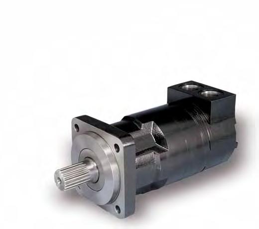


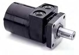
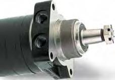
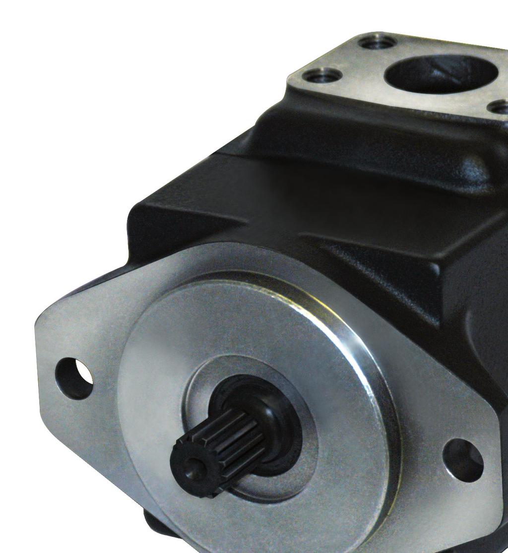
66 LSHT Torqmotors and Nichols Motors 1/ Fixed Displacement

67 1/ Fixed Displacement Torqlink Low Speed High Low Speed High Torque Motors Specifications Parker full line of high and low speed motors provide power ranging up to 15,000 inch-pounds of torque with speed ranging from 1/2 rpm to 13,000 rpm. complete range of sizes is offered in gear, gerotor, vane and piston style operating configurations. Fixed and variable displacement motors are available. Parker hydraulic motors deliver excellent performance with high efficiency, true wear compensation and longer service life. Product Lines Max Max supply Motor Range Displacement Max Speed Max Oil Flow Differential Pressure Pressure cont / int T cc/rev cont rev/min cont / int bar bar l/min Max Torque Max Performance cont / int Nm max KW 48 / T / / T / / / T / / / T / / / T / / / T / / / T / / / T / / / T / / / T / / / T / / / T / / / T / / / T / / / T / / / Max Side load at key T 4,900 N 67
68 1/ Fixed Displacement Torqlink Low Speed High Low Speed High Torque Motors Specifications Motor Range Displacement Max Speed TE /TJ cc/rev cont / int rev/min Max Oil Flow cont / int l/min Max Differential Pressure Max supply Pressure Max Torque Max Performance cont / int bar bar cont / int Nm max KW TE / / / / TE / / / / TE / / / / TE / / / / TE / / / / TE / / / / TE / / / / TE / / / / TE / / / / TE / / / / TE / / / / TE / / / / TE / / / / TE / / / / TE / / / / TF cc/rev cont / int rev/min cont / int l/min cont / int bar bar cont / int Nm max KW TF / / / / TF / / / / TF / / / / TF / / / / TF / / / / TF / / / / TF / / / / TF / / / / TF / / / / TF / / / / TF / / / / TG, G, TH cc/rev cont / int rev/min cont / int l/min cont / int bar bar cont / int Nm max KW TG/G,TH / / / / TG/G,TH / / / / TG/G,TH / / / / TG/G,TH / / / / TG/G,TH / / / / TG/G,TH / / / / TG/G,TH / / / / TG/G,TH / / / / TG/G,TH / / / / TG/G,TH / / / / TG/G,TH / / / / TG/G,TH / / / / TK cc/rev cont / int rev/min cont / int l/min cont / int bar bar cont / int Nm max KW TK / / / TK / / / TK / / / TK / / / TK / / / TK / / / TK / / / Max Side load at key TE 6,650 N Max Side load at key TF 16,000 N Max Side load at key TG/G 16,000 N TH 21,360 N Max Side load at key TK 26,245 N Intermittent operation rating applies to 10% of every minute 68

...125 bar Cont (3897 lb in) 440 Nm Int (to 2400 psi).")
69 1/ Fixed Displacement T Series Low Speed High Torque Motors Technical Information This light to medium duty motor incorporates all the features of heavy duty motors. Design features include a high pressure shaft seal so external drains are never required, roller vane technology for automatic wear compensation, and full flow internal cooling and flushing. This is a very economical motor for most light to medium duty applications. 15 Displacements ( in 3 /rev cm 3 /rev Maximum Pressure Maximum Oil Flow Maximum Speed Maximum Torque Maximum Side Load at Key Cont (to 1800 psi) bar Cont (3897 lb in) 440 Nm Int (to 2400 psi) bar (to 15 gpm)...57 lpm (932 rpm) 932 rpm Int (4783 lb in) 540 Nm (to 1100 lb) N 69
70 1/ Fixed Displacement T Series Low Speed High Torque Motors Ordering Information T XXXX XX XX 0 XXXX Series Displacement cc/rev cu in 3 /rev Displacements ( in 3/ rev) cm 3 /rev Maximum Pressure Maximum Oil Flow Maximum Speed Maximum Torque Maximum Side Load at Key Cont (to 1800 psi) bar Cont (3897 lb in) 440 Nm Int (to 2400 psi) bar (to 15 gpm)...57 lpm (932 rpm) 932 rpm Int (4783 lb in) 540 Nm (to 1100 lb) N Options Options No Paint lack Paint Rotation 0 Standard Shaft 09 1" Straight w/0.38 Crosshole M Mounting/Ports SE "" 2 olt, 5/16-18 UNC Manifold " Keyed Standard S SE "" 2 olt, 7/8-14 SE 11 1" 6 Spline 13 Long 1" Keyed FS 4 olt 7/8-14 SE 25 1" Tapered 26 25mm Keyed w/8mm Key Seal Kit Standard SK Seal Kit Viton SK High Temp Commutator Seal
71 1/ Fixed Displacement TE Series Low Speed High Torque Motors Technical Information n improved medium duty low speed, high torque motor This medium duty motor has higher pressure ratings than the T motor, for applications requiring higher torque. Robust roller bearings withstand higher side loads and are suitable for chain and sprocket shaft connections. It uses high pressure shaft seals, robust roller bearings and high flow shaft seal cooling. 15 Displacements ( in 3/ rev) cm 3 /rev Maximum Pressure Maximum Oil Flow Maximum Speed Maximum Torque Maximum Side Load at Key Cont (to 2030 psi) bar Cont (4139 lb in) 467 Nm Int (to 2750 psi) bar (to 20 gpm)...75 lpm (1000 rpm) 1000 rpm Int (5728 lb in) 648 Nm (to 1500 lb) N 71
72 1 1/ Fixed Displacement TE Series Ordering Information TE XXXX XX XX 0 XXXX Low Speed High Torque Motors Series Displacement cc/rev cu in 3 /rev Options Options No Paint lack Paint Rotation 0 Standard Shaft 09 1" Straight w/0.38 Crosshole M Mounting/Ports SE "" 2 olt, 5/16-18 UNC Manifold " Keyed Standard S SE "" 2 olt, 7/8-14 SE 11 1" 6 Spline 13 Long 1" Keyed FS 4 olt 7/8-14 SE 25 1" Tapered 26 25mm Keyed w/8mm Key US Wheel Mount, 7/8-14 SE Seal Kit Standard SK Seal Kit Viton SK High Temp Commutator Seal
73 1/ Fixed Displacement Small Frame Options Small Frame Speed Sensor n economical sensor for speed readout Low Speed High Torque Motors This rugged, weather resistant design is ideal for industrial and mobile applications. pplications include salt/sand/fertilizer spreader drives, conveyor drives and injection molder compression drives. The sensor is hall-effect type, which when externally powered outputs 30 square wave digital pulses per coupling shaft revolution. The connector is a user friendly universally available 4 pin polarized M12 connector allowing for simplified field service. The integrated design does not effect the side load capacity or performance of the torque motor. 1 US equivalents for metric specifications are shown in ( ). * Option code FS is with a single black coat of paint Maximum operating pressure 172 bar (2500 psi). Small Frame Internal Relief Valve This integrated internal relief valve is used for fixed pressure settings. LSHT Torqmotors and Nichols Motors Options Pressure bar (psi) CM 83 (1200) CK Operating pressure 120 (1740) CN 140 (2030) Other options are available, please contact Parker. 73
74 1/ Fixed Displacement TF Series Low Speed High Torque Motors 1 Technical Information tough motor for tough applications Sturdy construction throughout makes Parker's TF Series motors suitable for the most severe applications. The powertrain uses patented 60:40 spline geometry for strength. ll splines are constantly flushed with cool fluid for durability. Roller vanes and sealed commutation assure high volumetric efficiency, smooth low speed operation and extended life. 11 Displacements ( in 3/ rev) cm 3 /rev Maximum Pressure Maximum Oil Flow Maximum Speed Maximum Torque Maximum Side Load at Key Cont (to 3000 psi) bar Cont (6027 lb in) 681 Nm Int (to 4000 psi) bar (to 25 gpm)...95 lpm (749 rpm) 749 rpm Int (8106 lb in) 916 Nm (to 3597 lb) N 74
75 1/ Fixed Displacement TF Series Ordering Information TF XXXX XX XX 0 XXXX Low Speed High Torque Motors 1 Series Options Options Displacement cc/rev cu in 3 /rev No Paint lack Paint Rotation 0 Standard Shaft 01* 1" 6 Spline Mounting/Ports SE "" 2 olt, 5/16 UNC Manifold 02* 1" Keyed M /4" Keyed SE "" 2 olt, 7/8-14 SE S /4 14 Tooth Spline S SE "" 2 olt 7/8-14 SE Tooth Spline Magneto, 7/8-14 SE Tooth Spline MS Wheel Mount, 7/8-14 SE /4 Tooth Spline US Seal Kit Standard SK Seal Kit Viton SK High Temp Commutator Seal *Coupling shaft ø 1 inch Max. torque cont./int. = 450/550 Nm 75
76 1 1/ Fixed Displacement TG Series Low Speed High Torque Motors Technical Information Exceptional strength and durability in a high performance motor The heart of Parker's TG Series powertrain, the Torqlink, is an extra heavy duty part includes patented 60:40 spline geometry. Rugged construction throughout allows the transmission of over 13,000 lb-in of torque. The entire powertrain is continually washed in cool, high flow fluid to assure long life. Roller vanes and sealed commutator maintain high efficiency and provide smooth low speed performance. 13 Displacements ( in 3/ rev) cm 3 /rev Maximum Pressure Cont (to 3000 psi) bar Int (to 4000 psi) bar Maximum Oil Flow Maximum Speed Maximum Torque Maximum Side Load at Key Cont (9239 lb in) 1044 Nm (to 30 gpm) lpm (660 rpm) 660 rpm Int (12636 lb in) 1428 Nm (to 3597 lb) N 76
77 1/ Fixed Displacement TG Series Ordering Information TG XXXX XX XX 0 XXXX Low Speed High Torque Motors 1 Series Displacement cc/rev cu in 3 /rev Options Options No Paint lack Paint Rotation 0 Standard Shaft 01* 1" 6 Spline M Mounting/Ports SE "" 2 olt, 5/16-18 UNC Manifold /4" Keyed /4" 14 Tooth SE "" 2 olt, 7/8-14 SE Tooth Spline S 4 olt 7/8-14 SE /4" Taper MS /8" Taper US Wheel, Front rake Nose, 7/8-18 SE Seal Kit Strandard SK Seal Kit Viton SK High Temp Commutator Seal *Coupling shaft ø 1 inch Max. torque cont./int. = 450/550 Nm 77

 141...959 cm 3 /rev Maximum Pressure Cont (to 3000 psi)...207 bar Int (to 4000 psi).")
78 1/ Fixed Displacement TH Series Low Speed High Torque Motors Technical Information Rugged Motor for Heavy Duty, High Side Load pplications This motor was designed for tough applications. stout drive link with unique 60:40 spline geometry will transmit over 13,000 lb-in of torque. The 1-1/2" output shaft can support 7000 pounds of radial load. Efficiency is assured by the use of roller vanes and seal commutator. Durability is maintained by continually washing the power splines and shaft seal in cooling fluid. 13 Displacements ( in 3/ rev) cm 3 /rev Maximum Pressure Cont (to 3000 psi) bar Int (to 4000 psi) bar Maximum Oil Flow Maximum Speed Maximum Torque Maximum Side Load at Key Cont (8772 lb in) 991 Nm (to 30 gpm) lpm (660 rpm) 660 rpm Int (11876 lb in) 1342 Nm (to 4800 lb) N 78
79 1/ Fixed Displacement TH Series Ordering Information TH XXXX XX XX 0 XXXX Low Speed High Torque Motors 1 Series Displacement cc/rev cu in 3 /rev Options Options No Paint lack Paint Rotation 0 Standard Shaft /2" J501 Taper PS Mounting/Ports SE "" 4 olt, 7/8-14 SE /2" Keyed /2" 17 Tooth 4 olt 7/8-14 SE MS US Wheel, Front rake Nose, 7/8-18 SE Seal Kit Strandard SK Seal Kit Viton SK High Temp Commutator Seal
80 1/ Fixed Displacement Large Frame Options Low Speed High Torque Motors 1 Speed Sensor n Economical sensor for speed readout This rugged, weather resistant design is ideal for industrial and mobile applications. pplications include salt/ sand/ fertiliser spreader drives, conveyor and injection molder compression drives. The sensor is a hall effect type which when externally powered outputs 30 square wave digital pulses per coupling shaft revolution. The connector is a user friendly universally available 4 pin polarised M12 connector allowing for simplified field service. The integrated design does not effect the side load capacity or performance of the torque motor. Maximum operating pressure 172 bar (2500 psi). 80
81 1/ Fixed Displacement Large Frame Options Low Speed High Torque Motors Internal relief valve : *, *, C*, D* or G* This integrated internal relief valve is used for fixed pressure settings. 1 L (1.09) W kg (4.5lb) Ordering system Options Pressure bar (psi) * 69 (1000) * 138 (2000) * Opening pressure 207 (3000) * 276 (4000) * 103 (1500) 81

82 1/ Fixed Displacement TK Series Technical Information Exceptional strength and durability in a high performance motor Low Speed High Torque Motors The heart of Parker's TK Series powertrain, the torque link, is an extra heavy duty part that includes patented 60:40 spline geometry. Rugged construction throughout allows the transmission of over 23,000 lb-in of torque. The entire powertrain is continually washed in cool, high flow fluid to assure long life. Roller vanes and sealed commutator maintain high efficiency and provide smooth low speed performance. 1 7 Displacements (15.3 to 61.1 in 3/ rev) cm 3 /rev Maximum Pressure Cont (to 3000 psi) bar Int (to 4000 psi) bar Maximum Oil Flow Maximum Speed Maximum Torque Maximum Side Load at Key Cont (21360 lb in) 2413 Nm (to 60 gpm) lpm (523 rpm) 523 rpm Int (23540 lb in) 2660 Nm (to 5900 lb) N TK XXXX X5 XX 0 XXXX Series Displacement cc/rev cu in 3 /rev Options 0 Standard Options No Paint lack Paint Rear Port Rotation K5 Mounting/Ports Standard SE CC, 1 5/16-12 SE Rear Radical 32 Shaft 1 1/2" Keyed Wheel Mount, 1 5/16-12 SE Rear Radical /2" 17 Tooth 12/24 Spline T /4" Tapered Seal Kit SK mm Keyed 82


83 1/ Fixed Displacement Competitive Crossover Low Speed High Torque Motors Visit this link: 83


84 1/ Fixed Displacement pplication Market Market gricultural Marine & Offshore Construction Material Handling Mining & Drilling Low Speed High Torque Motors pplications Harvester, ale Wrappers, Grass cutter, Mower, Conveyors, Slewing, Winches, Cranes, Hoists Rotating Pulverizer, Loaders, Concrete Trailers, Mini-Skid Steers, Tailgate Spreader, Dump/Spreader erial Lift (Utility Trucks), Sorting graps, Wood Shredder, Walking-Floor Trailer Drill rig, Screener 84

85 1/ Fixed Displacement Literature Low Speed High Torque Motors Ref. Catalogue : HY /US,EU 85


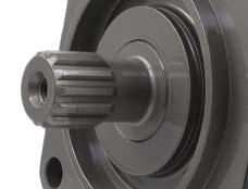


86 xial Piston Pumps and Motors 1/ Fixed Displacement
87 1/ Fixed Displacement xial Piston F11 Series xial Piston Pumps and Motors 1 Pressures up to 420 bar High overall efficiency (low losses) ccept high external shaft loads Good resistance to vibrations and temperature shocks Proven reliability Easy to service CETOP, ISO and SE versions available Frame size* F Displacement (cc/rev) Max cont pressure (bar) ,400 9, Max operating speed ( rpm) 12,800 11,200 10,200 Weight (kg) * Use F12 for medium range displacement CETOP MOUNT Frame Size Displacement Order Mount Dimension Shaft Type 4.9 cc/rev mm 18mm keyed F M-CV-K mm keyed F R-CN-K F Description F cc/rev mm F cc/rev mm 20mm keyed F M-CV-K F cc/rev mm 20mm keyed F H-CV-K P F cc/rev mm 25mm keyed F H-CV-K P F cc/rev mm 25mm keyed F M-CN-K ISO MOUNT Displacement Order Mount Dimension Shaft Type F Frame Size 9.8 cc/rev mm 20mm key F M-IV-K F cc/rev mm Spline Din 5480 F M-IV-D mm key F H-IV-K P Spline Din 5480 F H-IV-D P F cc/rev mm F cc/rev mm Displacement Order Mount Dimension Description SE MOUNT Frame Size 6 cc/rev SE, 2 olt F cc/rev SE, 2 olt F cc/rev SE, 2 olt F Shaft Type Description 20mm Key F MU-SV-K mm Key F MU-SV-K SE, Spline F HU-SV-S P F cc/rev SE, 2 olt SE, Spline F HU-SV-S P F cc/rev SE, 2 olt SE, Spline F RU-SV-S F cc/rev SE, 2 olt SE, Spline F MU-SV-S
88 1/ Fixed Displacement xial Piston F11 Series xial Piston Pumps and Motors Ordering codes F11 F11-CETOP Frame size Function Main ports Mounting flange Shaft seal Shaft Version number Option Option page 6 page 7, 67 (see catalogue) Frame size Displacem. (cm 3 /rev) Frame size Function M Motor x x x - - x Q Motor, low noise x - x x x x S Motor, high speed - - (x) (x) (x) (x) H Motor, high pressure (x) - (x) - - (x) R Pump, clockwise rot'n (x) - (x) (x) (x) (x) L Pump, counter clockw. (x) - (x) (x) (x) (x) For other versions, contact Parker Hannifin Frame size Main ports SP threads x x x x x x U SE, UN threads (x) (x) (x) (x) (x) (x) Version number (assigned for special versions) Frame size Option 0000 Standard x x x x x x MUVR Make up/nti - - (x) (x) (x) (x) cavitation valve clockwise rotation MUVL Make up/nti cavitation valve counter clockwise rotation - - (x) (x) (x) (x) Frame size Shaft* K Metric key x x x x x x J Metric key (x) (x) (x) (x) - - P Metric key (x) - Spline, DIN (x) (x) (x) - - D Spline, DIN 5480 x x x x x x S Spline, SE (x) V Tapered shaft - (x) (x) (x) (x) (x) *See also dimensional drawings (see catalogue) Frame size Mounting flange C CETOP flange x x x x x x W Saw motor flange - (x) (x) (x) (x) (x) Frame size Shaft seal N NR, low pressure (x) (x) (x) - - (x) V FPM, high pressure, high temperature x x x x x x S PTFE, high speed - (x) (x) (x) (x) (x) x: vailable (x): Optional : Not available Frame size Option 00 Standard x x x x x x P_ Prepared for speed sensor - (x) (x) (x) (x) (x) _ Power oost and Prepared for speed sensor - (x) (x) (x) (x) (x) _T Painted lack (x) (x) (x) (x) (x) (x) 88
89 1/ Fixed Displacement xial Piston F11 Series xial Piston Pumps and Motors Ordering codes F11 F11-SE Frame size Function Main ports Mounting flange Shaft seal Shaft Version number Option Option page 6 page 7, 67 (see catalogue) Frame size Displacem. (cm 3 /rev) Frame size Function M Motor x x - - x Q Motor, low noise - x x x x S Motor, high speed - (x) (x) (x) (x) H Motor, high pressure - (x) - - (x) R Pump, clockwise rot'n - (x) (x) (x) (x) L Pump, counter clockw. - (x) (x) (x) (x) For other versions, contact Parker Hannifin Frame size Main ports U SE, UN threads x x x x x SP threads (x) (x) (x) (x) (x) Version number (assigned for special versions) Frame size Option 0000 Standard x x x x x MUVR Make up/nti - (x) (x) (x) (x) cavitation valve clockwise rotation MUVL Make up/nti cavitation valve counter clockwise rotation - (x) (x) (x) (x) Frame size Shaft* T SE key x x S SE spline x x x x x K Metric key x x x x x J Metric key (x) (x) (x) - - P Metric key (x) - V Tapered shaft (x) (x) (x) (x) (x) *See also dimensional drawings (see catalogue) Frame size Mounting flange S SE flange x x x x x Frame size Shaft seal N NR, low pressure (x) (x) - - (x) V FPM, high pressure, high temperature x x x x x S PTFE, high speed (x) (x) (x) (x) (x) x: vailable (x): Optional : Not available Frame size Option 00 Standard x x x x x P_ Prepared for speed sensor (x) (x) (x) (x) (x) _ Power oost and Prepared (x) (x) (x) (x) (x) for speed sensor _T Painted lack (x) (x) (x) (x) (x) 89
90 1/ Fixed Displacement xial Piston F12 Series xial Piston Pumps and Motors 1 Pressures up to 480 bar High power capability High overall efficiency Small envelope size ISO, SE and cartridge versions available Proven reliability Easy to service Material Specifications Frame size F Displacement (cm3/rev) Max cont pressure (bar) Max operating speed ( rpm) Weight (kg) ISO MOUNT Frame Size Displacement Order Mount Dimension Shaft Type Description F cc/rev mm 30mm key F MF-IV-K F cc/rev mm Spline Din 5480 F MF-IV-D F cc/rev mm 30mm key F MF-IV-K F cc/rev mm Spline Din 5480 F MF-IV-D F cc/rev mm 35mm key F MF-IV-K F cc/rev mm Spline Din 5480 F MF-IV-D F cc/rev mm 40mm key F MF-IV-K F cc/rev mm Spline Din 5480 F MF-IV-D F cc/rev mm 40mm key F MF-IV-K F cc/rev mm Spline Din 5480 F MF-IV-D F cc/rev mm 45mm key F MF-IV-K F cc/rev mm Spline Din 5480 F MF-IV-D F cc/rev mm 45mm key F MF-IV-K F cc/rev mm Spline Din 5480 F MF-IV-D F cc/rev mm Spline Din 5480 F SF- IV- K
91 1/ Fixed Displacement xial Piston F12 Series Ordering codes xial Piston Pumps and Motors F12 F12-ISO Frame size Function Main ports Mounting flange Shaft seal Shaft Version number Option Option page 6, 61 page 7, 67 (see catalogue) Frame size Displacem. (cm 3 /rev) Frame size Function M Motor x x x x x x x x x x S Motor, high (x) (x) (x) (x) (x) (x) speed R Pump, (x) (x) (x) (x) (x) (x) (x) clockwise rotation L Pump, counter clockwise rot'n (x) (x) (x) (x) (x) (x) (x) For other versions, contact Parker Hannifin Frame size Main ports F SE 6000 psi x x x x x x x x x x flange D SE 6000 psi (x) (x) (x) Horizontal SE 6000 psi xial (x) (x) (x) K SE 6000 psi Rear (x) (x) (x) M SE 6000 psi Side (x) (x) (x) Frame size Mounting flange I ISO flange x x x x x x x x x x F ISO 200 flange x x x Frame size Shaft* D DIN Spline, x x x x x x x x x x Standard DIN Spline, Optional - (x) Z DIN Spline, Optional (x) (x) (x) (x) (x) (x) (x) (x) (x) (x) K Metric key, x x x x x x x x x x Standard J Metric key, - (x) Optional H DIN Spline, (x) (x) (x) Optional G Metric key, (x) (x) (x) Optional P Metric key, Optional (x) (x) (x) (x) V Tapered shaft (x) (x) (x) - - (x) (x) *See also dimensional drawings (see catalogue) Frame size Option 0000 Standard x x x x x x x x x x L130 Flushing valve 1.3 mm orifice (x) (x) (x) (x) (x) - 1) - 1) MUVR Make up/nti (x) cavitation valve clockwise rotation MUVL Make up/nti cavitation valve counter clockwise rotation (x) P R Pressure relief valve (x) (x) (x) ) clockwise rotation P L 2) Pressure relief valve counter clockwise rotation Version number (assigned for special versions) (x) (x) (x) Frame size Option 00 Standard x x x x x x x x x x P_ Prepared for speed sensor (x) (x) (x) (x) (x) (x) (x) (x) (x) (x) _ Power oost and Prepared for speed sensor (x) _T Painted lack (x) (x) (x) (x) (x) (x) (x) (x) (x) (x) 3 x: vailable (x): Optional : Not available 1) F and -125: ccessory valve block (see catalogue) 2) Pressure setting (see catalogue) Frame size Shaft seal N NR, low pressure (x) (x) (x) (x) (x) (x) (x) (x) (x) (x) V FPM, high pressure, x x x x x x x x x x high temperature S PTFE, high speed (x)
 Frame size F12 30.0 40.0 59.8 80.4 93.0 110.1 125.0 150.0 242.")
92 1/ Fixed Displacement xial Piston F12 Series xial Piston Pumps and Motors 1 Pressures up to 480 bar High power capability High overall efficiency Small envelope size ISO, SE and cartridge versions available Proven reliability Easy to service Material Specifications Displacement (cm3/rev) Frame size F Max cont pressure (bar) Max operating speed ( rpm) Weight (kg) SE MOUNT Frame Size Displacement Order Shaft Type Mounting F cc/rev SE - (1 ) Key SE, 2 olt F MS-TV-T P Description F cc/rev SE-, Spline SE, 2 olt F MS-TV-S F cc/rev SE - (1 ) Key SE -4 olt F MS-SV-T F cc/rev F cc/rev F cc/rev F cc/rev F cc/rev F cc/rev F cc/rev F cc/rev F cc/rev F cc/rev F cc/rev FF cc/rev F SE, Spline SE C ( ) Key SE C, Spline SE C (1.250 ) Key SE C, Spline SE C (1.250 ) Key SE -4 olt F MS-SV-S SE, 2 olt F MS-TV-T SE, 2 olt F MS-TV-S P SE C, 4 olt F MS-SV-T SE C, 4 olt F MS-SV-S SE, 2 olt F MS-TV-T SE, 2 olt F MS-TV-S P SE C, 4 olt F MS-SV-T SE C, 4 olt F MS-SV-S SE C-C (1.50 ) Key SE C, 4 olt F MS-SV-T SE C-C, Spline SE C, 4 olt F MS-SV-S SE C-C, Spline SE C, 4 olt F MS-SV-S cc/rev SE C-C, Spline SE C, 4 olt F MS-SV-S P SE C, Spline SE C ( ) Key SE C, Spline F cc/rev SE D, Spline SE D, 4 olt F MS-SV-S F cc/rev SE D (1.75 ) Key SE D, 4 olt F MS-SV-S F cc/rev SE D, Spline SE D, 4 olt F SF-SV-S F cc/rev SE D, Spline SE D, 4 olt F SF-SV-S F cc/rev SE D, Spline SE D, 4 olt F SF-SV-S F cc/rev SE D, Spline SE D, 4 olt F QF-SV-D F cc/rev SE D, 4 olt F QF-SV-D DIN
93 1/ Fixed Displacement xial Piston F12 Series Catalogue HY /UK Ordering codes xial Piston Pumps and Motors F12 F12-SE Frame size Frame size Displacem. (cm 3 /rev) Function Main ports x: vailable (x): Optional : Not available 1) F and -125: ccessory valve block (see catalogue) 2) Metric threads 3) Pressure setting (see catalogue) 4) Not in combination with any valve options Mounting flange Frame size Function M Motor x x x x x x x x x x - S Motor, high (x) (x) (x) (x) (x) (x) - speed Q Motor x R Pump, (x) (x) (x) (x) (x) (x) (x) (x) clockwise rotation L Pump, counter clockwise rot'n (x) (x) (x) (x) (x) (x) (x) (x) For other versions, contact Parker Hannifin x x x x (x) (x) (x) (x) (x) (x) (x) (x) (x) (x) (x) (x) - Frame size Main ports S SE 6000 psi x x x x x x x flange U SE UN (x) (x) (x) (x) (x) (x) (x) threads 4) F SE 6000 psi flange 2) D SE 6000 psi Horizontal 2) SE 6000 psi xial 2) K SE 6000 psi Rear 2) M SE 6000 psi Side 2) Frame size Mounting flange S SE 4 bolt x x x x x x x x x x x R SE 4 bolt (x) (x) T SE 2 bolt x x x Shaft seal Shaft Frame size Shaft* T SE key, Standard x x x x x x x x x x x R SE key, Optional (x) (x) S SE Spline, Optional x x x x x x x x x x x F SE Spline, (x) (x) - - (x) (x) (x) (x) Optional U SE Spline, Optional (x) (x) K Metric key, x Standard D Spline DIN (x) V Tapered shaft (x) (x) (x) - - (x) (x) *See also dimensional drawings (see catalogue) Frame size Option 0000 Standard x x x x x x x x x x x L130 Flushing valve (x) (x) (x) (x) (x) - 1) - 1) mm orifice MUVR Make up/nti (x) cavitation valve clockwise rotation MUVL Make up/nti cavitation valve counter clockwise rotation (x) P R 3) P L 3) Pressure relief valve clockwise rotation Pressure relief valve counter clockwise rotation Version number Option page 6, 61 Option page 7, 67 (see catalogue) Version number (assigned for special versions) (x) (x) (x) (x) (x) (x) Frame size Option 00 Standard x x x x x x x x x x x P_ Prepared for speed (x) (x) (x) (x) (x) (x) (x) (x) (x) (x) (x) sensor _ Power oost and Prepared for speed sensor (x) _T Painted lack (x) (x) (x) (x) (x) (x) (x) (x) (x) (x) (x) Frame size Shaft seal N NR, low pressure (x) (x) (x) (x) (x) (x) (x) (x) (x) (x) - V FPM, high pressure, x x x x x x x x x x x high temperature S PTFE, high speed (x)
94 1/ Fixed Displacement F11/F12 Spare Parts xial Piston Pumps and Motors 1 VLVE PLTES Frame Size Displacement Part Number Design Detail Weight (kg) F cc/rev Valve Plate- Left Hand (Type L) 0.1 F cc/rev Valve Plate- Right Hand (Type R) 0.1 F cc/rev Valve Plate- Motor H 0.1 F cc/rev Valve Plate- Left Hand (Type L) 0.1 F cc/rev Valve Plate- Right Hand (Type R) 0.1 F cc/rev Valve Plate- Motor H 0.1 F cc/rev Valve Plate- Left Hand (Type L) 0.1 F cc/rev Valve Plate- Right Hand (Type R) 0.1 F cc/rev Valve Plate- Motor H 0.1 F cc/rev Valve Plate- Left Hand (Type L) 0.1 F cc/rev Valve Plate- Right Hand (Type R) 0.1 F cc/rev Valve Plate- Motor H 0.1 F cc/rev Valve Plate- Left Hand (Type L) 0.1 F cc/rev Valve Plate- Right Hand (Type R) 0.1 F cc/rev Valve Plate- Motor H 0.1 F cc/rev Valve Plate- Left Hand (Type L) 0.2 F cc/rev Valve Plate- Right Hand (Type R) 0.2 F cc/rev Cylinder arrel (Pump) 0.2 F cc/rev Valve Plate- Motor M 0.2 F cc/rev Valve Plate- Left Hand (Type L) 0.2 F cc/rev Valve Plate- Right Hand (Type R) 0.2 F cc/rev Cylinder arrel (Pump) 1.5 F cc/rev Valve Plate- Motor M 0.2 F cc/rev Valve Plate- Left Hand (Type L) 0.2 F cc/rev Valve Plate- Right Hand (Type R) 0.2 F cc/rev Cylinder arrel (Pump) 1.8 F cc/rev Valve Plate- Motor M 0.2 F cc/rev Valve Plate- Left Hand (Type L) 0.2 F cc/rev Valve Plate- Right Hand (Type R) 0.2 F cc/rev Cylinder arrel (Pump) T F cc/rev Valve Plate- Motor M 0.2 F cc/rev Valve Plate- Left Hand (Type L) 1.5 F cc/rev Valve Plate- Right Hand (Type R) 0.5 F cc/rev Cylinder arrel (Pump) 2.5 F cc/rev Valve Plate- Motor M 0.5 SPRE PRTS KITS Order Frame size Description Contain Weight (kg) F Type N Valveplate, Cylinder barrel, pistons and N seals F Type N Valveplate, Cylinder barrel, pistons and N seals F Type S Valveplate, Cylinder barrel, pistons and S seals F Type N Valveplate, Cylinder barrel, pistons and N seals F Type S Valveplate, Cylinder barrel, pistons and S seals F Type M Valveplate, Cylinder barrel and pistons F Type M Valveplate, Cylinder barrel and pistons F Type M Valveplate, Cylinder barrel and pistons F Type M Valveplate, Cylinder barrel and pistons F Type M Valveplate, Cylinder barrel and pistons F Type M Valveplate, Cylinder barrel,needle bearings and pistons F Type M Valveplate, Cylinder barrel,needle bearings and pistons F Type M Valveplate, Cylinder barrel,needle bearings and pistons


95 1/ Fixed Displacement pplication Market xial Piston Pumps and Motors Markets Forestry Industrial Marine Oil & Gas Construction Mining Material Handling Recycling Military pplications Saw Drives, Feller unchers, Skidder, Forwarder, Cranes, Mowers / Cutters ircraft Test Stands Deck Cranes, Constant Tension Winches, Hatch Covers Nitrogen Pumpers, Frac Trucks, Coil Tubing Skid Steer, Off-Highway Trucks, Fan Drives, Cranes, Dust Collector, Excavator Drill Rigs, Top Drives, Loaders, Subsurface Loaders, Tunneling Equipment Conveyor Drives, Truck Mounted Cranes, Mixers Shredders, Vaccum Truck Systems Fan Drives 95

96 1/ Fixed Displacement Literature xial Piston Pumps and Motors Ref. Catalogue : HY /UK 96

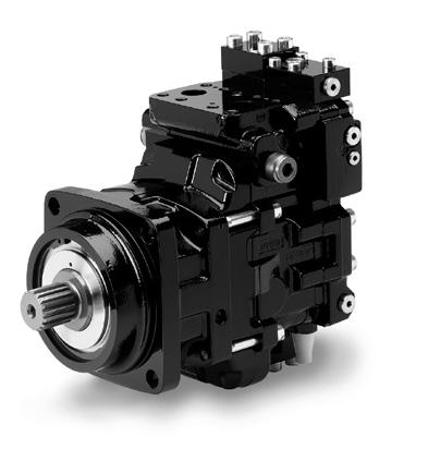
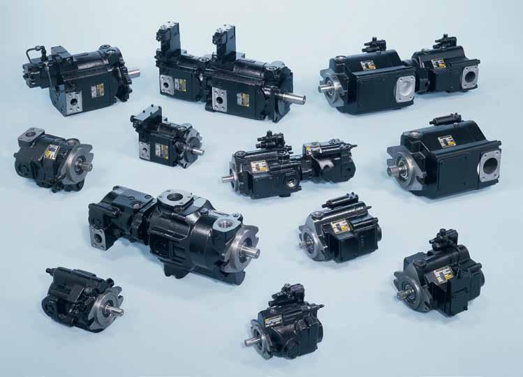
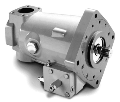
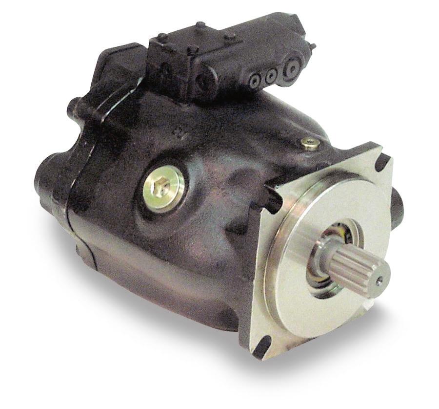
97 Pump and Motors Variable Displacement Pumps 2/ Variable Displacement
98 2/ Variable Displacement Quick View Pumps 98
 Load Sensing Power (Torque) Limiting Sealed Shaft earing Power and Load Sensing Two Piece Design for Ease of Service Remote Pressure Compensation Cartridge Type Controls - Field")
99 2/ Variable Displacement PVC Series Pumps Variable xial Piston Pumps Controls Features High Strength Cast-Iron Housing Pressure Compensation uilt-in Supercharger Ensures High Speed Capability RPM (2600 RPM PVC100) Load Sensing Power (Torque) Limiting Sealed Shaft earing Power and Load Sensing Two Piece Design for Ease of Service Remote Pressure Compensation Cartridge Type Controls - Field Changeable djustable Maximum Volume Stop Replaceable ronze Clad Port Plate Low Pressure irbleed Standard for Quick Priming Hydrodynamic Cylinder arrel earing Thru-Shaft (PVC100 Only) Full Pressure Rating on Most Water Glycol Fluids Pump Case and Shaft Seal are Subjected to Inlet Pressure Only Filter and/or Cool Drain Line 7 bar (100 PSI) Maximum Quick Reference Data Chart Pump Model Pump 21 bar (300 PSI) in LPM (GPM) Displacement CM3/REV (IN3/REV) 1200 RPM 1800 RPM *pprox. Noise Levels Full Flow 1800 RPM (1200 RPM) 34 bar 69 bar 138 bar 207 bar (500 PSI) (1000 PSI) (2000 PSI) (3000 PSI) PVC33 33 (2.0) 39.4 (10.4) 59.0 (15.6) 75 (69) 76 (72) 78 (75) 79 (77) PVC38 38 (2.3) 45.0 (11.9) 67.8 (17.9) 75 (69) 76 (72) 78 (75) 79 (77) PVC65 65 (4.0) 78.7 (20.8) (31.2) 77 (75) 78 (76) 80 (78) 81 (79) PVC (6.1) (31.6) (47.5) 83 (77) 82 (78) 82 (79) 85 (80) Input Power t 1800 RPM, Maximum Displacement & 207 bar (3000 PSI) 21.3 kw (28.5 hp) 24.6 kw (33.0 hp) 43.1 kw (57.8 hp) 71.2 kw (95.5 hp) Operating Speed RPM (Maximum) Pressure bar (PSI) Continuous (Maximum) (3000) (3000) (3000) (3000) Preferred Models Model Description 99
100 2/ Variable Displacement PVC Conversion Parts & Spares Pumps *Please read footnote regarding series Seal Kits PVC Order SKPVC3326/3816 SKPVC6513 SKPVC10022 Port Plate PVC Description PVC33-38 Nitrile PVC65 Nitrile PVC100 Nitrile * The above part numbers are taken from series pumps mentioned below. Including PVC 33 Series 26, PVC38 Series 16, PVC65 Series 13 PVC100 Series 22 Rotating Group Kits PVC Shaft ss'y PVC Order Description X19 PVC33-38 Shaft ss'y, SE'' STR, 7/8" Keyed Omit PVC33-38 Shaft ss'y, SE'' 13T, Splined X19 PVC33-38 (Option 9) Shaft ss'y, SE'' STR, 7/8" Keyed Omit PVC33-38 (Option 9) Shaft ss'y, SE'' 13T, Splined PVC65 Shaft ss'y, SE'C' STR, 1 1/4", Keyed Omit PVC65 Shaft ss'y, SE'C' 14T, Splined PVC65 (Option 9) Shaft ss'y, SE'C' STR, 1 1/4" Keyed Omit PVC65 (Option 9) Shaft ss'y, SE'C' 14T, Splined X31 PVC100 Shaft ss'y, SE'C' STR, 1 1/4" Keyed Omit PVC100 Shaft ss'y, SE'C' 14T Splined X45 PVC100 Shaft ss'y, SE'C-C' STR, 1 1/2" Keyed C PVC100 Shaft ss'y, SE'C-C' 17T, Splined D X31 PVC100 (Option 9) Shaft ss'y, SE'C' STR, 1 1/4" Keyed Omit PVC100 (Option 9) Shaft ss'y, SE'C' 14T Splined X45 PVC100 (Option 9) Shaft ss'y, SE'C-C' STR, 1 1/2" Keyed C PVC100 (Option 9) Shaft ss'y, SE'C-C' 17T, Splined D Through-drive dapter Kit (Only for PVC100) Order RRKPVC33R26 RRKPVC33L26 RRKPVC38R16 RRKPVC38L16 RRKPVC65R13 RRKPVC65R13 RRKPVC100R22 Order Description DPTER KIT SE '-' Pilot, 9T 20/40 pitch coupling DPTER KIT SE '' Pilot, 9T 16/32 pitch coupling DPTER KIT SE '' Pilot, 13T 16/32 pitch coupling DPTER KIT SE '' Pilot, 15T 16/32 pitch coupling DPTER KIT SE 'C' Pilot, 14T 12/24 pitch coupling 6C3 Order Description PVC33-38, RH Rotation PVC33-38, LH Rotation PVC65, RH Rotation PVC65, LH Rotation PVC100, RH Rotation PVC100, LH Rotation Description PVC33, RH Rotation PVC33, LH Rotation PVC38, RH Rotation PVC38, LH Rotation PVC65, RH Rotation PVC65, RH Rotation PVC100, RH Rotation 100
101 2/ Variable Displacement PVC Series Catalog HY CD/US Ordering Information Pumps PVC 4 Omit Multiple Pumps Pump xial Piston Variable Controllable Displacement earing Option Shaft Option Outlet Port Inlet Port Rotation Volume Stop djustable Option Differential Thru- Thru- Control Shaft Shaft Options Nitrile Threads Variations (Standard) Seals Paint Multiple Pumps Omit Multiple Pumps Single Pump Factory Mounted to Rear of nother Pump Inlet Port 33/38 Inlet 65 Inlet 100 Inlet Type Omit Str. Thd., Rear Str. Thd., Rear Flange, Rear SE/Inch Threads 2 Flange, Side Flange, Top Flange, Top/ottom SE/Inch Threads Displacement in 3 /rev (cm 3 /rev) (33) (38) (65) (100) earing Option Omit Single Piece Shaft 9* Dual earing * For applications where side loading may be experienced. Max. side load = kg (250 lbs). Typical pplications: elt/chain drive Universal joint drive Massive couplings Foot mount installations Shaft Option Size 33/38 Size 65/100 Omit 7/8" Keyed SE 1¼" Keyed SE C 13T Spline SE 14T Spline SE C C* 1½" Keyed SE CC D* 17T Spline SE CC * Size 100 only Outlet Port Outlet Location Type Omit Str. Thread Top SE/Inch 3* Flange Top SE/Inch * Size 100 only Chart #1 Item Setting RPM PSI HP Rotation* R Right CW L Left CCW * Viewed from shaft end. Volume Stop Options Omit Volume Stop Plugged 2 Maximum Volume Stop 5* Max. Volume Stop with O-ring * Not available with Thru- Shaft option on Size 100. Thru-Shaft Threads* Omit No Thru-Shaft 6 Thru-Shaft, UNC * vailable on Size 100 only. Omit 3 4 *3 *4 *C3 Ordering Notes Unless otherwise specified, pump is shipped at maximum GPM (1800 RPM) and set to 69 bar (1000 PSI) [See Exceptions]. When factory settings are required, the items shown in Chart #1 must be included with order. Thru-Shaft Variations No Thru-Shaft Option Thru-Shaft, SE Pilot, 9 Tooth 20/40 Pitch Spline Coupling, PVC 100 Only Thru-Shaft, SE Pilot, 9 Tooth 16/32 Pitch Spline Coupling, PVC 100 Only Thru-Shaft, SE Pilot, 13 Tooth 16/32 Pitch Spline Coupling, PVC 100 Only Thru-Shaft, SE Pilot, 15 Tooth 16/32 Pitch Spline Coupling, PVC 100 Only Thru-Shaft, SE C Pilot, 14 Tooth 12/24 Pitch Spline Coupling, PVC 100 Only Inlet port option 2 or 8 (top/bottom) must be used with all Thru-Shaft pumps. * Use SE C-C shaft on thru-shaft pump variation when combined input torque of front and rear pumps exceeds 565 N m (5000 In-Lbs). Control Option Standard Pressure Compensated Omit Setting Pressure bar ( PSI) Pressure & Flow (Load Sensing) *C Pressure, Flow & Power *H Pressure Comp. & Power ** M Remote Pressure ** ME Remote Pressure M Remote Pressure & Flow * CM Remote Pressure, Flow & Power * HM Remote Pressure & Power * Power controlled pumps (H, C, HM or CM) must have maximum input power limit specifications at a particular drive speed (RPM) and compensator pressure setting (PSI) included with order. Power controlled pumps that do not have input power limit specifications, will be set at default setting ( RPM and 3000 PSI) H & C ( RPM and 3000 PSI) HM & CM ** M may be remotely controlled; ME requires external pilot Pumps with M, ME, M, CM or HM controls will be set to compensate at 207 bar (3000 PSI) unless Chart #1 specifies otherwise. Omit P No Paint Paint Painting Multiple Pumps Omit Single Pump Pump Factory Mounted on Rear GPM = Omit if not required or to select standard option coded omit. 101
102 2/ Variable Displacement PVC Series Pumps Piston Pumps (Mobile & Industrial) PVC Medium Pressure/Super Charged Piston Pumps Front View Side View D E C ROTTION RROW F J G (Rear, Side or Top Ports) G (ottom Ports) Dimensions, inch (mm) H (ottom Port) Dim. PVC33/38 PVC65 PVC100 Rear Ported Side Ported Rear Ported Top Ported Rear Ported Top/ottom Ported 7.25 (184.15) 7.32 (185.93) 8.82 (224.03) 8.82 (224.02) (303.53) (310.13) 0.37 (9.39) 0.37 (9.37) 0.49 (12.45) 0.49 (12.44) 0.49 (12.44) 0.49 (12.44) C 2.31 (58.67) 2.31 (58.67) 2.19 (55.63) 2.19 (55.62) 2.19 (55.62) 2.19 (55.62) D 3.31 (84.07) 4.17 (105.92) 4.00 (101.60) 4.00 (101.60) 4.25 (107.95) 4.25 (107.94) E 3.31 (84.07) 3.53 (89.66) 4.00 (101.60) 4.00 (101.60) 4.25 (107.95) 4.25 (107.94) F 2.50 (63.50) 2.50 (63.50) 3.50 ( (85.85) 4.62 (117.34) 4.50 (114.30) G 3.81 (96.77) 4.12 (104.65) 4.56 (115.82) 4.56 (115.82) 5.57 (141.47) 6.25 (159.25) H 9.37 (237.99) J 6.24 (158.49) 6.24 (159.49) enefits/features High strength cast-iron housing uilt-in supercharger ensures high speed capability RPM (2600 RPM PVC100). Sealed shaft bearing Two-piece design for ease of service Cartridge type controls fiel changeable Replaceable bronze clad port plate irbleed standard for quick priming Hydrodynamic cylinder barrel bearing Thru-shaft (PVC100 only) Full pressure rating on most water glycol fluid Pump case and shaft seal are subjected to inlet pressure only Filter and/or cool drain line100 PSI (7 R) maximum 102

103 2/ Variable Displacement PVC Series Pumps PVC Mobile pplication Market Market Forestry Oil & Gas Construction Utility Harsh Environment gricultural pplications Nitrogen Pumpers, Cementers, Coil Tubing Fan Drives Cranes, Salt, Steel Mill Salt & Sand Trucks pplications PVC Industrial pplication Market Markets Industrial Oil & Gas Material Handling pplications Power Units, Industrial Molding Oil Lift Pumps, Suitable for non mineral oil, Water Glycol Conveyor Drives Literature Ref. Catalogue : HY CD/US 103
104 2/ Variable Displacement PVP Series Pumps Industrial Piston Pumps Characteristics High speed capability High strength cast-iron housing 100% of power available at through shaft Low noise levels promote more comfortable operating environment Suitable for high water content fluid operation 2 Features Continuous Pressure up to 248 bar Through-shaft Capability djustable Maximum Volume Stop 4 Control Types for sizes 16, 23/33 cc/rev 5 Control Types for 41/48 cc/rev PVP Series Piston Pumps PVP16 PVP23 PVP33 PVP41 PVP48 Max. Displacement 16 cc/rev 23 cc/rev 33 cc/rev 41 cc/rev 48 cc/rev Speed Rating: RPM RPM RPM RPM RPM Cont. Outlet Press: 248 bar 248 bar 248 bar 248 bar 248 bar Min. Inlet Press:* 0.17 bar 0.17 bar 0.17 bar 0.17 bar 0.17 bar Max. Inlet Press: 1.72 bar 1.72 bar 1.72 bar 1.72 bar 1.72 bar Input Power:** 13.1 kw 19.7 kw 27.2 kw 33.2 kw 40.3 kw 1800 RPM, Maximum RPM, Maximum. Displacement and 248 bar Preferred Models Model PVP1636L2 PVP1636R2 PVP16362R26T PVP2336R2 PVP23362R2 PVP3336R2 PVP33362L2 PVP33362R2 PVP4836C2L2 PVP4836CR2 PVP4836C2R Description 16cc/rev, L/H rotation, rear ported 16cc/rev, R/H rotation, rear ported 16cc/rev, R/H rotation, side ported 23cc/rev, R/H rotation, rear ported 23cc/rev, R/H rotation, side ported 33cc/rev, R/H rotation, rear ported 33cc/rev, L/H rotation, side ported 33cc/rev, R/H rotation, side ported 48cc/rev, L/H rotation, side ported 48cc/rev, R/H rotation, rear ported 48cc/rev, R/H rotation, side ported 104
105 2/ Variable Displacement PVP Series Industrial Piston Pumps PVP16-40 Conversion Parts & Spares *Please read footnote regarding series Pumps Compensators PVP Order Description PVP Comp Flow & Press '' PVP Comp Remote Press 'M' PVP Comp Std Press 'Omit' Horse power block ss PVP Order Description PVP 16 'H' and 'C' PVP 'H' & 'C' PVP 'H' & 'C' Shafts PVP Order Description PVP 16 Shaft SE STR, 3/4" Keyed omit PVP 16 Shaft SE STR Thru, 3/4" - Keyed omit PVP 16 Shaft SE SPL, 9 Tooth '' PVP 16 Shaft SE SPL Thru, 9 Tooth '' PVP 16 Shaft SE SPL, 11 Tooth 'C' PVP 16 Shaft SE SPL Thru, 11 Tooth 'C' PVP Shaft SE STR, 7/8" Keyed omit PVP Shaft SE STR Thru, 7/8" Keyed omit PVP Shaft SE SPL, 13 Tooth '' PVP Shaft SE SPL Thru, 13 Tooth '' PVP Shaft SE STR, 1" Keyed omit PVP Shaft SE STR Thru, 1" Keyed '' PVP Shaft SE SPL, 15 Tooth '' PVP Shaft SE SPL Thru, 15 Tooth '' PVP Shaft SE STR, 7/8" Keyed omit PVP Shaft SE SPL, 7/8" Keyed '' PVP Shaft SE STR, 1"Keyed 'C' PVP Shaft SE SPL, 1"Keyed 'D' Servo Piston PVP Order Description PVP 16 CC PVP 23 CC PVP 33 CC PVP 41 CC PVP 48 CC Port Plates PVP Order Description PVP 16 RH Rotation PVP 16 LH Rotation PVP RH Rotation PVP LH Rotation PVP RH Rotation PVP LH Rotation * The above part numbers are taken from series pumps mentioned below. Including PVP 16 Series 12, PVP 23/33 SERIES 20, PVP 41/48 SERIES 10, 105
106 2/ Variable Displacement PVP Series Industrial Piston Pumps PVP16-48 Conversion Parts & Spares * Please read footnote regarding series Pumps Seal Kits PVP Order SKPVP1611 SKPVP16V11 SKPVP23/3320 SKPVP23/33V20 SKPVP41/4810 SKPVP41/48V10 Description PVP 16 Nitrile PVP 16 Viton PVP 23/33 Nitrile PVP 23/33 Viton PVP 41/48 Nitrile PVP 41/48 Viton 2 Through-drive PVP Order Description PVP16 Pilot 9T Spl PVP23/33 Pilot 9T Spl PVP23/33 Pilot 11T Spl PVP23/33 Pilot 13 T Spl PVP23/33 Pilot 15 T Spl PVP41/48 Pilot 9T Spl PVP41/48 Pilot 11T 5pl PVP41/48 Pilot 13T Spl PVP41/48 Pilot 15T Spl 64 Rotating Group PVP Order RRKPVP16R12 RRKPVP16L12 RRKPVP23/33R20 RRKPVP23/33L20 RRKPVP41/48R11 RRKPVP41/48L11 Description PVP 16 RH Rotation PVP 16 LH Rotation PVP 23/33 RH Rotation PVP 23/33 LH Rotation PVP 41/48 RH Rotation PVP 41/48 LH Rotation * The above part numbers are taken from series pumps mentioned below. Including PVP 16 Series 12, PVP 23/33 SERIES 20, PVP 41/48 SERIES
107 2/ Variable Displacement PVP Series Industrial Piston Pumps Pumps PVP 2 Size Displacement cc/rev cc/rev cc/rev cc/rev cc/rev Pressure Range ar Shaft Pilot Pump Omit 3/4" Keyed x 1.75 Long SE '' 16 Only Omit 7/8" Keyed x 2.31 Long SE '' ll except 16 9T Spline (SE '') SE '' 16 Only 13T Spline (SE '') SE '' ll except 16 C 11T 11/62 DP Spline SE '' 16 Only C 1" Keyed x 1.88" Long (SE '') SE '' ll except 16 D 15T Spine (SE '') SE '' ll except 16 Port Location Port Type Pump Omit Rear Straight Thread SE ll 2 Side Flange (Inch Thds.) SE ll Paint Omit Not Painted P Painted Seals Seals Omit una N V Fluroelastomer Control Options Pump Omit Press. Compensated ll M Remote Pressure (Int.) ll Pressure & Flow ll C Press, Flow & Power ll H Horsepower Limiting ll Thru -Shaft Option Pump Omit No Thru-Shaft ll T Thru with Cover 16 Only 4 SE "" Pilot 9T Spline ll except 16 5 SE "" Pilot 11T Spline ll except 16 3 SE "" Pilot 13T Spline ll except 16 4 SE "" Pilot 15T Spline ll except 16 R L Rotation CW CCW Thru-Shaft Threads Omit No Thru-Shaft 6 UNC Omit 2 Volume Stop No Volume Stop dj. Max. Volume Stop 107

108 2/ Variable Displacement PVP Series Pumps Markets Industrial Oil & Gas Power Gen Material Handling Power Units, Industrial Molding, Press Oil Lift Pumps Turbine Start Conveyor Drives pplications Literature Ref. Catalogue : HY CD/US 108
109 2/ Variable Displacement P1-PD Series P1/PD Series for open circuits Pumps 18 cc/rev, 28 cc/rev, 45 cc /rev, 60 cc/rev, 75 cc/rev, 100 cc/rev, 140 cc/rev Characteristics: Variable displacement, axial, piston, P1 and PD pumps have been designed to meet the specific demands of mobile and industrial applications. Range expanded to cover 7 displacements 18 cc/rev to 140 cc/ rev. Mobile version P1, designed with an emphasis on speed capability achieves max RPM Industrial version PD with reduced speed capability is designed for quieter operation. For open loop applications operating to 280 bar continuous pressure. Various port location options and full power through drive capability are other features offered by this range of pumps. 2 Features: P1 Mobile version High Speed PD Industrial version Low noise Continuous pressure to 280 ar Intermittent pressure to 320 ar Peak pressure 350 bar Through drive capable oosted inlet speeds to 3600 RPM Max & Min Volume Stop Wide variety of control options Series pump model *Intermittent pressure is defined as less than 10% of ope ation time, not exceeding 6 successive seconds. P1 018 P1 028 P1 045 P1 060 P1 075 P1 100 P1 140 Displacement maximum cc/rev continuous bar Outlet pressure *intermittent bar peak bar max. boosted inlet rpm Speed (mobile version) P1 max. 1.0 bar absolute rpm max. 0.8 bar absolute rpm minimum rpm C - 4 D - 4 C - 2 bolt or C - 4 bolt Flange SE bolt bolt bolt bolt bolt Keyed shaft SE 3/4" 1" 1" 1 1/4" 1 1/4" 1 1/2" 1 3/4" Mounting 3/4" 11T 1" 15T 1" 15T 1 1/2" Splined shaft SE 1 1/4" 14T 1 1/4" 14T 17T 1 1/4" 5/8" 9T 7/8" 13T 7/8" 13T Splined shaft option SE 14T End port kg Weight Side port kg Thru drive kg /4" 13T 109
110 2/ Variable Displacement P1-PD Series Pumps Preferred Model (Industrial) Model PD018PS02SRS5C00E PD018PS02SRS5C00R PD028PS02SRS5C00R PD028PS02SRS5C00E PD045PS02SRS5C00R PD045PS02SRS5L00R PD060PS02SRS5C00S PD060PS02SRS5L00S PD075PS02SRS5C00S PD075PS02SRS5L00S PD100PS02SRS5C00S PD100PS02SRS5L00S PD140PS02SRS5C00S PD140PS02SRS5L00S Description 18 cc/rev, R/H rotation, End ported, Pressure Comp, Key Shaft 18 cc/rev, R/H rotation, Side ported, Pressure Comp, Key Shaft 28 cc/rev, R/H rotation, Side ported, Pressure Comp, Key Shaft 28 cc/rev, R/H rotation, Side ported, Pressure Comp, Key Shaft 45 cc/rev, R/H rotation, Side Ported, Pressure Comp, Key Shaft 45 cc/rev, R/H rotation, Side Ported, Load Sense, Key Shaft 60 cc/rev, R/H rotation, Side Ported, Pressure Comp, Key Shaft 60 cc/rev, R/H rotation, Side Ported, Load Sense, Key Shaft 75 cc/rev, R/H rotation, Side ported, Pressure Comp, Key Shaft 75 cc/rev, R/H rotation, Side ported, Load Sense, Key Shaft 100 cc/rev, R/H rotation, Side ported, Pressure Comp, Key Shaft 100 cc/rev, R/H rotation, Side ported, Load Sense, Key Shaft 140 cc/rev, R/H rotation, Side ported, Pressure Comp, Key Shaft 140 cc/rev, R/H rotation, Side ported, Load Sense, Key Shaft Preferred Model (Mobile/Universal) Model P1018PS02SRM5C00E P1018PS02SRM5C00R P1018PS01SRM5C00E120P00 P1018PS01SLM5C00E P1028PS02SRM5C00E P1028PS02SRM5C00R P1028PS01SLM5C00E P1028PS08SRM5C00R100P00 P1028PS08SRM5L00R120P00 P1045PS02SRM5C00E P1045PS02SRM5C00R P1045PS01SRM5C00R P1045PS01SRM5L00R P1045PS01SLM5L00R P1045PS01SRU5L00R P1075PS02SRM5C00S P1075PS02SRM5L00S P1075PC01SRM5C00S P1075PC02SRM5C00S P1075PC01SRM5L00S P1075PC01SLM5L00S P1075PC02SRM5L00S P1100PS02SRM5C00S P1100PS01SRM5C00S P1100PS01SRM5L00S P1100PS01SLM5L00S P1100PS02SRU5C00S P1140PS02SRM5C00S P1140PS01SRM5C00S P1140PS01SRM5L00S P1140PS01SLM5L00S P1140PS02SRU5C00S Description 18 cc/rev, R/H rotation, End ported, Pressure Comp, Key Shaft, No paint 18 cc/rev, R/H rotation, Side ported, Pressure Comp, Key Shaft, No paint 18 cc/rev, R/H rotation, End ported, Pressure Comp, Splined Shaft, Painted lack 18 cc/rev, L/H rotation, End ported, Pressure Comp, Splined Shaft, No paint 28 cc/rev, R/H rotation, End ported, Pressure Comp, Key Shaft, No paint 28 cc/rev, R/H rotation, Side ported, Pressure Comp, Key Shaft, No paint 28 cc/rev, L/H rotation, End ported, Pressure Comp, Splined Shaft, No paint 28 cc/rev, R/H rotation, Side ported, Pressure Comp, Splined Shaft, Painted lack 28 cc/rev, R/H rotation, Side ported, Load Sensing, Splined Shaft, Painted lack 45 cc/rev, R/H rotation, End ported, Pressure Comp, Key Shaft 45 cc/rev, R/H rotation, Side ported, Pressure Comp, Key Shaft 45 cc/rev, R/H rotation, Side ported, Pressure Comp, Splined Shaft 45 cc/rev, R/H rotation, Side ported, Load Sense, Splined Shaft 45 cc/rev, L/H rotation, Side ported, Load Sense, Splined Shaft 45 cc/rev, R/H rotation, Side ported, Load Sense, Splined Shaft, Universal 75 cc/rev, R/H rotation, Side ported, Pressure Comp, Key Shaft 75 cc/rev, R/H rotation, Side ported, Load Sense, Key Shaft 75 cc/rev, R/H rotation, Side ported, Pressure Comp, Splined Shaft, SE'C' 2-bolts 75 cc/rev, R/H rotation, Side ported, Pressure Comp, Key Shaft, SE'C' 2-bolts 75 cc/rev, R/H rotation, Side ported, Load Sense, Splined Shaft, SE'C' 2-bolts 75 cc/rev, L/H rotation, Side ported, Load Sense, Splined Shaft, SE'C' 2-bolts 75 cc/rev, R/H rotation, Side ported, Load Sense, Key Shaft, SE'C' 2-bolts 100 cc/rev, R/H rotation, Side Ported, Pressure Comp, Key Shaft 100 cc/rev, R/H rotation, Side Ported, Pressure Comp, Splined Shaft 100 cc/rev, R/H rotation, Side Ported, Load Sense, Splined Shaft 100 cc/rev, L/H rotation, Side Ported, Load Sense, Splined Shaft 100 cc/rev, R/H rotation, Side ported, Pressure Comp, Key Shaft, Universal 140 cc/rev, R/H rotation, Side ported, Pressure Comp, Key Shaft 140 cc/rev, R/H rotation, Side ported, Pressure Comp, Splined Shaft 140 cc/rev, R/H rotation, Side ported, Load Sense, Splined Shaft 140 cc/rev, L/H rotation, Side ported, Load Sense, Splined Shaft 140 cc/erv, R/H rotation, Side ported, Pressure Comp, Key Shaft, Universal 110
111 2/ Variable Displacement P1-PD Series Pumps Seal Kits and Parts Kits Seal Kits S2E K S2E K S2E K S2E K S2E K S2E K S2E K Note: Seal kits contain all the seals required for any pump configuration. Rotating Group Kits CW Mobile P1 S2E K S2E K S2E K S2E K S2E K S2E K S2E K CW Mobile P1 with Ripple Chamber S2E K S2E K S2E K ** ** ** ** CCW Mobile P1 S2E K S2E K S2E K S2E K S2E K S2E K S2E K CCW Mobile P1 w/ Ripple Chamber S2E K S2E K S2E K ** ** ** ** CW Industrial PD S2E K S2E K S2E K S2E K S2E K S2E K S2E K CW Industrial PD w/ Ripple Chamber S2E K S2E K S2E K ** ** ** ** CCW Industrial PD S2E K S2E K S2E K S2E K S2E K S2E k S2E K CCW Industrial PD w/ Ripple Chamber S2E K S2E K S2E K ** ** ** ** Rotating Group Kit includes barrel s/a, pistons, retainer, washer, pins, port plate Torque Limiter Control Kits Torque Limiter Kit for MT Control S2E S2E S2E S2E S2E Torque Limiter Kit for LT Control See Note ** ** ** Torque Limiter Kit for L0T ** ** S2E S2E S2E Torque Limiter Kits includes cartridge assembly, tubing and fittings. Note: M control can be converted to an L control with conversion kit S2E European customers will receive a solid spool in this kit. US customer will receive a set screw to plug orifice in spool. Minimum and Maximum Volume Stop Item # Qty Description5 KIT S2E S2E S2E S2E K S2E K djustable Volume Stop KIT S2E S2E Use bove Kit djustable Minimum Volume Stop Maximum and minimum volume stops use the same components except where noted. Thru Drive Pad Coupling #70 Thru Drive Couplings O-ring SE, 9 Tooth S2E S2E E E E E E SE, 11 Tooth S2E S2E E E E E ** SE, 13 Tooth ** S2E E E E E E SE, 15 Tooth ** S2E E E E E E SE C, 14 Tooth ** ** ** 03E E E E SE CC, 17 Tooth ** ** ** ** ** 03E E SE D&E, 13 Tooth ** ** ** ** ** ** 03E
112 2/ Variable Displacement P1-PD Series Pumps P1/ PD Series - 18cc, 28cc, 45cc Ordering Information 2 * U Universal (045 Only) * * *For sizes 028 & 045 only * * Flange Ports Threaded Ports * size18 with Thru-Drive only * Not available with Thru-Drive L Load sense and Pressure limiter (P*45 TLO Only) 112
113 2/ Variable Displacement P1-PD Series Pumps and Motors P1/ PD Series - 60cc, 75cc, 100cc, 140cc Ordering Information * U Load sense and pressure limiter (only with "T" Torque Limiter option) * Not functional control as such Torque limiter MT ll Sizes Torque limiter LOT 75,100,140 Torque limiter LT 045 and 060 only 113
 0.24 (6.2) 1.29 (32.8) 4.72 (120) 2.97 (75.5) 2.60 (66) 4.24 (107.7) 4.80 (122) P1/PD028 9.25 (235.5) 0.37 (9.5) 1.84 (46.8) 4.72 (120) 3.21 (81.5) 2.93 (74.5) 4.48 (113.8) 4.80 (122) P1/PD045 9.")
114 2/ Variable Displacement P1-PD Series Pumps and Motors Piston Pumps (Mobile & Industrial) P1/PD Medium Pressure Mobile Piston Pumps G F D H E C Dimensions, inch (mm) Series C Max. D E F G H Max. P1/PD (164.2) 0.24 (6.2) 1.29 (32.8) 4.72 (120) 2.97 (75.5) 2.60 (66) 4.24 (107.7) 4.80 (122) P1/PD (235.5) 0.37 (9.5) 1.84 (46.8) 4.72 (120) 3.21 (81.5) 2.93 (74.5) 4.48 (113.8) 4.80 (122) P1/PD (228.7) 0.37 (9.5) 1.84 (46.8) 4.72 (120) 3.63 (92.3) 2.92 (74.2) 4.75 (120.7) 4.80 (122) P1/PD060 (9.96 (253.0) 0.50 (12.7) 2.24 (56.8) 4.72 (120) 3.98 (101.2) 3.23 (82) 4.88 (123.9) 4.80 (122) P1/PD (263.5) 0.50 (12.7) 2.24 (56.8) 4.72 (120) 4.09 (103.8) 3.54 (90) 5.03 (127.7) 4.80 (122) P1/PD (339.6) 0.50 (12.7) 2.47 (62.8) 4.72 (120) 4.61 (117.1) 3.98 (101) 5.66 (143.7) 4.80 (122) P1/PD (364.3) 0.50 (12.7) 2.97 (75.5) 4.72 (120) 5.24 (133) 4.45 (113) 6.13 (155.7) 4.80 (122) enefits/features Compact overall package size Quiet operation Low flow ripple to further reduce noise Elastomer seals that eliminate gaskets and external leakage High operating efficiency for lower power consumption and reduced heat generation Simple hydraulic controls with no-leak adjustments SE and ISO standard mounting flanges and ports Long life, tapered-roller shaft bearings Long life, low friction, hydrostatically balanced cam bearings Full power through-drive capability End or side inlet and outlet ports Case drain ports for horizontal or vertical, shaft-up mounting Optional minimum and maxi-mum displacement adjustments Optional case-to-inlet check valve to extend shaft seal life Easy to service P1/PD 114


115 2/ Variable Displacement P1-PD Series P1 Mobile pplication Market Pumps Markets Forestry Oil & Gas Construction Mining Power Gen Recycling Military Utility pplications Feller unchers, Knuckle oom Loader, Skidder, Forwarder, Cranes Nitrogen Pumpers, Cementers, Coil Tubing DTs, Fan Drives Drill Rigs, Top Drives, Loaders, Dump Trucks, Tunneling Equipment Lube Oil Skids Shredders, alers, Compactors, Vacuum Truck Systems, Refuse Trucks - SL, Rear Loaders Fan Drives Cranes, Digger Derricks, Man Lifts, Cable Placers, Fan Drives, Horizontal Directional Drills 115


116 2/ Variable Displacement P1-PD Series Pumps PD Industrial pplication Market Markets pplications Industrial Oil & Gas Power Units, Industrial Molding, Press Oil Lift Pumps Power Gen Turbine Start Material Handling Conveyor Drives Literature Ref. Catalogue HY /PT 116
117 2/ Variable Displacement P2 Series Pumps Characteristics 2 Low noise levels rigid housing design and reduced pressure ripple Compact design and unique port layout High self priming speed extends service life Modular controls allow for future control variations Features Continuous Pressure up to 320 bar Through-shaft Capability djustable Maximum Volume Stop 8 Control Options 4 Capacities from 60 cc/rev to 145 cc/rev * Self-priming 1 bar (absolute) Max Speed P2060 P2075 P2105 P2145 Max. Displacement 60 cc/rev 75 cc/rev 105 cc/rev 145 cc/rev Speed:* 2800 RPM 2500 RPM 2300 RPM 2200 RPM Cont. Outlet Press: 320 bar 320 bar 320 bar 320 bar Min. Inlet Press.** 0.8 bar 0.8 bar 0.8 bar 0.8 bar Max. Inlet Press.** 10 bar 10 bar 10 bar 10 bar Max. Case Drain Press: 0.5 bar 0.5 bar 0.5 bar 0.5 bar Preferred Models P2060L00C1C25L20N00T11P P2060R00C1C25L20N00T11P P2075L00C1C25L20N00T11P P2075R00C1C25L20N00T11P P2105L00C1C25L20N00T11P P2105R00C1C25L20N00T11P P2145L00C1C25L20N00T11P P2145R00C1C25L20N00T11P P2145R00D1D25L20N00T11P P2145L00D1D25L20N00T11P Description 60cc/rev LH, Load Sense, 'C' 4 bolt Flange 'C' spline 60cc/rev RH, Load Sense, 'C' bolt flange C' spline 75cc/rev LH, Load Sense, 'C Flange 'C' spline 75cc/rev RH, Load Sense, 'C Flange 'C' spline 105cc/rev LH, Load Sense, 'C Flange 'C' spline 105cc/rev RH, Load Sense, 'C Flange 'C' spline 145cc/rev LH, Load Sense, 'C Flange 'C' spline 145cc/rev RH, Load Sense, 'C Flange 'C' spline 145cc/rev RH, Load Sense, 'D Flange 'D' spline 145cc/rev LH, Load Sense, 'D Flange 'D' spline 117
118 2/ Variable Displacement P2 Series Pumps P2 Pump Compensator Options Compensator Option Pump Size^^ Order Press. Comp. (Pmax) P P N Press. Comp. (Pmax) P 60 P N Remote Press. Comp. R P N Remote Press. Comp. R 60 P N Load Sense Without leed L P N Load Sense Comp L Without leed 60 P N Torque/LS/Pmax 20-60% Without leed T With leed T ll Torque/LS/Pmax 50-90% Without leed TC With leed TD P N P2060 P N plus P P2075 P N plus P P2105 P N plus P2145 P N plus ^^ Option not available if pump is not shown P2 Pump Shaft Options Shaft Option SE 'C' Keyed C5 Pump Size^^ Order P2060 P P2075 P P2105 P P2145 P2075 SE 'C' Keyed C6 P P2105 P2145 SE 'D' Spline D1 SE 'D' Spline D3 P2105 P2145 P2145 ^^ Option not available if pump is not shown 118
119 2/ Variable Displacement P2 Series Pumps P2 Pump Through Drive Kits Thru-Drive Kits 2 Pump Size^^ Order P2060 P N P2075 P N P2105 P N P2145 P N P2060 P N P2075 P N P2105 P N P2145 P N P2060 P N P2075 P N P2105 P N P2145 P N P2060 P N P2075 P N P2105 P N P2145 P N P2145 P N P2060 P N P2075 P N P2105 P N P2145 P N SE "C" 4 olt, 'CC' Spline C4 P2145 P N SE "D" 4 olt, 'D' Spline D3 P2145 P N SE "" 2 olt, 9T Spline 1 SE "" 2 olt, '' Spline 1 SE "" 2 olt, '' Spline 2 SE "C" 2 olt, 'C' Spline C1 SE "C" 2 olt, 'CC' Spline C2 SE "C" 4 olt, 'C' Spline C3 ^^ Option not available if pump is not shown P2 Piston Pump Spares P2 Seal Kits P2060 Seal Kit una N SKP2060N P2075 SKP2/P3075N P2105 P
120 2/ Variable Displacement P2 Series Pumps Piston Pump Out P2 Size Displacement cc/rev cc/rev cc/rev cc/rev Rotation R CW L CCW Percent of Max. Displacement % Stroke, Std Factory Setting xx Range is 70 to 99 (70 to 99%) P U Port Location Paint Option Parker lack No Paint Multiple Pump Option 1 Single Pump Front Pump of Multiple Pump Combination Middle Pump of Multiple Pump Combination Rear Pump of Multiple Pump Combination Side Inline Flanges UNC 2 Shaft Options C1 SE 'C' Spline X X X X C5 SE 'C' Keyed X X X N/ C6 SE 'CC' Keyed N/ X X N/ D1 SE 'D' Spline N/ N/ X X D3 SE 'D' Keyed N/ N/ N/ X Mounting Flange C SE 'C' 4-olt SE 'C' 2/4-olt SE 'C' 2/4-olt D N/ N/ N/ SE 'C' 2-olt SE 'D' 4-olt Through Drive Control Options Pump S1 No Thru-Shaft ll T1 Thru with Cover ll 1 SE "" 2 olt 9T Spline ll 1 SE "" 2 olt '' Spline ll 2 SE "" 2 olt '' Spline ll C1 SE "C" 2 olt 'C' Spline ll C2 SE "C" 2 olt 'CC' Spline 145 Only C3 SE "C" 4 olt 'C' Spline ll C4 SE "C" 4 olt 'CC' Spline 145 Only D3 SE "O" 4 olt 'D' Spline 145 Only 25 Pressure Setting Factory max. setting in bar times 10 (100 to 320 bar range) Torque Control Setting in % 00 Std Setting for Non-torque Control Pumps XX 20 to 90% of Max. Rated Torque P R L L T T TC TD Control Options Std Setting for Non-torque Control Pumps Remote/Pmax 100 to 320 ar Load Sensing (2 Spool)/pmax without bleed orifi e Load Sensing (2 Spool)/pmax with bleed orifi e Torque/LS/Pmax without bleed orifi e (2 Spool) Torque Range 20 to 60% of Max Rated Torque Torque/LS/Pmax with bleed orifi e (2 Spool) Torque Range 20 to 60% of Max Rated Torque Torque/LS/Pmax without bleed orifi e (2 Spool) Torque Range 50 to 90% of Max Rated Torque Torque/LS/Pmax with bleed orifi e (2 Spool) Torque Range 50 to 90% of Max Rated Torque N D V T 20 XX Seals Nitrile Single Shaft Nitrile Double Shaft 'Wet Flange' Fluorocarbon Single Shaft Seal Fluorocarbon Double Shaft 'Wet Flange' Differential Pressure Setting Recommended Initial Factory Setting Presure Setting in ar Range 10 to 35 ar 120
 0.49 (12.5) 2.19 (55.6) 3.62 (92) 6.74 (171.3) 5.55 (141) 4.49 (114) P2075 12.9 (327.5) 0.49 (12.5) 2.44 (62.0) 4.41 (112) 7.63 (193.8) 5.71 (145) 4.84 (123) P2105 14.1 (358) 0.49 (12.5) 2.98 (75.")
121 2/ Variable Displacement P2 Series Pumps Piston Pumps (Mobile & Industrial) P2 High Pressure/High Speed Piston Pumps F G D E C Dimensions, inch (mm) Series Max* Max. C Max. D E Max. F G P (299) 0.49 (12.5) 2.19 (55.6) 3.62 (92) 6.74 (171.3) 5.55 (141) 4.49 (114) P (327.5) 0.49 (12.5) 2.44 (62.0) 4.41 (112) 7.63 (193.8) 5.71 (145) 4.84 (123) P (358) 0.49 (12.5) 2.98 (75.7) 4.41 (112) 8.35 (212.0) 6.89 (175) P (375) 0.50 (12.7) 2.98 (75.7) 4.65 (118) 8.86 (225.0) 7.13 (181) 6.46 (164) * With thru-shaft option enefits/features Compact Low noise level Sealed shaft bearing Service friendly Reliable Long-lasting Flexible Easy to install High self-priming speed 121


122 2/ Variable Displacement P2 Series Pumps Markets Forestry Construction Mining Material Handling Recycling pplications Feller unchers, Knuckle oom Loader, Skidder, Forwarder Wheel Loader, Dozers, Off-Highway Trucks, Drill Rigs, Loaders Truck Mounted Cranes, Lift Trucks, Reachstacker Shredders, alers, Compactors 122

123 2/ Variable Displacement P2 Series Pumps Literature Ref. Catalogue HY /PT 123
124 2/ Variable Displacement PV Plus Series Pumps Characteristics Continuous Pressure up to 350 bar 2 Through shaft Capability Low Outlet Flow Pulsation 7 Standard Control Options Feature Low noise levels Fast response Compact design Service friendly High self priming speed Through drive for 100% of nominal Modular controls PV016/020/023/028 PV032/040/046 PV063/080/092 PV140/180 PV270 PV360 16/20/23 cc/rev 32/40/46 cc/rev 63/80/92 cc/rev 140/180 cc/rev 270 cc/rev 360 cc/rev 3000 RPM 2800 RPM 2800/2500/ 2300 RPM 2400/2200 RPM 1800 RPM 1750 RPM Cont. Outlet Press: 350 bar 350 bar 350 bar 350 bar 350 bar 350 bar Min. Inlet Press. 0.8 bar 0.8 bar 0.8 bar 0.8 bar 0.8 bar 0.8 bar 16 bar 16 bar 16 bar 16 bar 16 bar 16 bar 15.5/19.5/ 22.5/ 27.5 kw 31/39/45 kw 6.1/78/7804 kw 138/175 kw 263 kw 350 kw Max. Displacement Speed Rating: Max. Inlet Press. Input Power*: * 1500 RPM and 350 bar. Model Description PV016R1K1T1NMMC 16cc/rev, RH press. Comp. Keyed shaft metric flang PV020R1K1T1NMMC 20cc/rev, RH press. Comp. Keyed shaft metric flang PV023R1K1T1NMMC 23cc/rev, RH press. Comp. Keyed shaft metric flang PV028R1K1T1NMMC 28cc/rev, RH press. Comp. Keyed shaft metric flang PV032R1K1T1NMMC 32cc/rev, RH press. Comp. Keyed shaft metric flang PV040R1K1T1NMMC 40cc/rev, RH press. Comp. Keyed shaft metric flang PV046R1K1T1NMMC 46cc/rev, RH press. Comp. Keyed shaft metric flang PV063R1K1T1NMMC 63cc/rev, RH press. Comp. Keyed shaft metric flang PV080R1K1T1NMMC 80cc/rev, RH press. Comp. Keyed shaft metric flang PV092R1K1T1NMMC 92cc/rev, RH press. Comp. Keyed shaft metric flang PV140R1K1T1NMMC 140cc/rev, RH press. Comp. Keyed shaft metric flang PV180R1K1T1NMMC 180cc/rev, RH press. Comp. Keyed shaft metric flang PV270R1K1T1NMMC 270cc/rev, RH press. Comp. Keyed shaft metric flang 124
125 2/ Variable Displacement PV Plus Series Pumps Piston Pump Options PV to SE Pilot & Coupling 9T PV to SE Pilot & Coupling 13T PV to PV Description Through Drive Kit* MK-PVG1MN42 MK-PVG1MN42 MK-PVG1JMN42 Coupling* MK-PVG1K1142 PV to PV PV to PV MK-PVG2MN40 MK-PVG2MN42 MK-PVG2JMN40 MK-PVG2KMN40 MK-PVG2K1140 MK-PVG2K1340 MK-PVG2K0140 MK-PVG2K0240 PV to PV PV to PV PV to PV MK-PVG3MN41 MK-PVG3MN41 MK-PVG3CMN41 MK-PVG3JMN41 MK-PVG3KMN41 MK-PVG3LMN41 MK-PVG3K1141 MK-PVG3K1341 MK-PVG3K1541 MK-PVG3K0141 MK-PVG3K0241 MK-PVG3K0341 MK-PVG4MN40 MK-PVG4MN40 MK-PVG4CMN40 MK-PVG4JMN40 MK-PVG4LMN40 MK-PVG4LMN40 MK-PVG4K1140 MK-PVG4K1340 MK-PVG4K1540 MK-PVG4K0140 MK-PVG4K0240 MK-PVG4K0340 MK-PVG4K0440 MK-PVG5KMN40 MK-PVG5LMN40 MK-PVG5LMN40 MK-PVG5MMN40 MK-PVG5K0240 MK-PVG5K0340 MK-PVG5K0440 MK-PVG5K0540 PV to SE C Pilot & Coupling 14T PV TO PV PV TO PV PV TO PV PV TO PV PV270 to PV PV270 to PV PV270 to PV PV270 to PV270 MK-PVG1K Compensator Options* Series 45 and up only PV PV Pressure Compensated MMC PVCMMCN1 PVCMCMCN1 PVCMEMCN1 PV140- Pressure & Flow Comp. MFC PVCMFCN1 PVCMCFCN1 PVCMEFCN1 Pressure & Flow Comp. c/w Top Interface NG6/D03 MF1 PVCMF1N1 PVCMCF1N1 PVCMEF1N1 Remote Press Comp. MRC PVCMRCN1 PVCMCRCN1 PVCMERCN1 Remote Press Comp. cc/w Top Interface NG6/D03 MR1 PVCMR1N1 PVCMCR1N1 PCVMER1N1 * More Compensator Options vailable on Request. Contact Parker. PV Plus Piston Pump Spares Seal Kits PV PV PV PV PV270 Seal Kit una N SK-PVG1N145 SK-PVG2N145 SK-PVG3N14 SK-PVG4N14 SK-PVG5N14 Seal Kit Viton SK-PVG1V145 SK-PVG2V145 SK-PVG2V14 SK-PVG4V14 SK-PVG5V14 125
126 2/ Variable Displacement PV Plus Series pumps PVplus cc Model Ordering PV Pump Variable Piston Displacement Rotation Pump Variations Displacement in /rev (cc/rev) 3 Shaft & Mounting Threads Thru-Drive Option Coupling Seals Control Options Thru-Drive Option (1st Digit) Second Pump (2nd Digit) T Single Pump Prepared for Thru-Drive 1 Single Pump, No Coupling With dapter for Second Pump H w/coupling, 25 x 1 5 x 15, DIN (16) (20) Y1 SE, 2 00in ( 50 8mm) J w/coupling, 32 x 1 5 x 20, DIN (23) SE, 3 25in ( 82 55mm) Y w/se Coupling, 9T-16/32 DP (28) SE, 4 00in ( 101 6mm) w/se Coupling, 11T-16/32 DP (32) C2 SE C, 5 00in ( 127mm) w/se Coupling, 13T-16/32 DP (40) G Metric, 2 48in ( 63mm) C* w/se Coupling, 15T-16/32 DP (46) H Metric, 3 15in ( 80mm) D w/se Coupling, 14T-12/24 DP J Metric, 3 94in ( 100mm) E w/se Coupling, 17T-12/24 DP K2 Metric, 4 92in ( 125mm) R CW L CCW *s viewed from shaft end Pump Variations 1 Standard 9* Customized Displacement and/or Pressure Setting *Specify in cc/rev and/or bar Shaft & Mounting PV016/020/023 Shaft Pilot PV032/040/046 Shaft Pilot 1¼" 4 olt Keyed SE C (SE C) D 1" Keyed 4 olt (SE ) SE E 15T 14T 4 olt 4 olt Spline Spline SE SE C (SE ) (SE C) K L 25mm Keyed 4 olt 100mm 32mm Keyed 4 olt 125mm W32 x W25 x x 20 x 15 4-olt x 8f 4 olt x 8f 100mm Spline 125mm Spline DIN DIN Port* Coupling 1 Single pump, no coupling H with coupling 25 x 1 5 x 15, DIN 5480 J with coupling 32 x 1 5 x 20, DIN 5480 Y with coupling SE 9T-16/32 DP with coupling SE 11T-16/32 DP with coupling SE 13T-16/32 DP C with coupling SE - 15T-16/32 DP D with coupling SE C 14T-12/24 DP Seals N Nitrile V Fluorocarbon W Nitrile w/ptfe Shaft Seal P FPM w/ptfe Shaft Seal Threads 1 Only for PV016 thru PV023 2 Only for PV032 and larger * Only for PV032 and larger 0 1 M M M M SPP Metric 3 UNF UNC 7 ISO 6149 UNC 8 ISO 6149 Metric *Drain, gage, and flushing ports ** Mounting and connecting threads 1 0 C 1 W K Z P C D E G H K M S L C Threads** M R F T C 1 W K Z NOTES: Compensator differential Dp is to be adjusted: Remote pressure comp, horsepower comp 15 ± 1 bar Load-sensing comp (not horsepower comp ) 10 ± 1 bar (s MF* and LS part of MT*) Consult catalog on CD for electrohydraulic control options. Items in red are standard. Control Options Standard Pressure Compensator No Compensator With Cover Plate, No Control Function Standard pressure control, integrated pilot valve Remote pressure control, integrated pilot valve Load Sensing (flow) control, integrated pilot valve Two spool LS control Remote/Load Sense Compensator Standard version 1 NG6 interface top side for pilot valves With unloading function, 24VDC solenoid 1 Prop -pilot valve type PVCRE 35 mounted Without integrated pilot valve, NG6 interface, for mounting of accessory code PVC MT1 with mounted pilot valve PVC1P 2 Horsepower Compensator Control Nominal Horsepower at 1500 RPM 3 HP (19 5 Nm Torque) 4 HP (26 Nm Torque) 5 5 HP (36 Nm Torque) 7 5 HP (49 Nm Torque) 11 HP (71 Nm Torque) 15 HP (97 Nm Torque) 18 5 HP (120 Nm Torque) 22 HP (142 Nm Torque) 30 HP (195 Nm Torque) Function Horsepower Compensator Horsepower Compensator & Load Sensing Variation PV032/040/046 Rotation* PV016/020/023 Standard Version NG 6 interface top side With unloading function, 24 VDC solenoid Pro-pilot valve type PVRCE...35 mounted Without integrated pilot valve, NG6 interface, for mounting of accessory code PVC*4) Without integrated pilot valve, without NG6 interface4) F U P P V Electro Hydraulic Control Options Proportional displacement control, no pressure compensation Proportional displacement control, with pressure compensation 1 Not for MT 2 Only for MT 126
127 2/ Variable Displacement PV Plus Series pumps PVplus cc Model Ordering PV (80) Thru-Drive Option (1st Digit) T Single Pump Prepared for Thru-Drive (92) (140) (180) (270) (360) C D1 E2 Rotation* R CW L CCW G3 H *s viewed from shaft end J Pump Variations 1 Standard K 9* Customized Displacement and/or Pressure Setting L1 *Specify in cc/rev and/or bar M2 Shaft & Mounting PV063/ PV140/ PV / Shaft Pilot Shaft Pilot Shaft Pilot D E F G K L 1¾" Keyed (SE D) 13T Spline (SE D) 4 2" 4 4 2" olt Keyed olt olt SE SE SE SE SE Keyed D F D E 4 15T 4 15T 4 olt Spline olt Spline olt SE SE SE SE SE D F D F E 1¾" 4 Keyed olt SE SE D D 13T 4 Spline olt SE SE D D mm olt 50mm olt 65mm olt Keyed 160 Keyed 160 Keyed 200 mm mm mm W40 x W50 x W60 x 1 5 x 4 2 x x olt x 9g olt x 9g olt x8f 160 Spline 160 Spline 200 Spline mm DIN mm DIN mm DIN *** 7 8 Metric, 2 48in ( 63mm) Metric, 3 15in ( 80mm) Metric, 3 94in ( 100mm) Metric, 4 92in ( 125mm) Metric, 6 30in ( 160mm) Metric, 7 87in ( 200mm) 0 1 M M 0 0 M R M M F T 1 Only for PV063 and larger 2 Only for PV270 3 Only up to PV092 D Coupling Single pump, no coupling with coupling 25 x 1 5 x 15, DIN 5480 with coupling 32 x 1 5 x 20, DIN 5480 with coupling 40 x 1 5 x 25, DIN 5480 with coupling 50 x 2 x 24, DIN 5480 with coupling SE 9T-16/32 DP with coupling SE - 11T-16/32 DP with coupling SE 13T-16/32 DP with coupling SE - 15T-16/32 DP with coupling SE C 14T-12/24 DP E with coupling SE C - C F with coupling SE D, E G with coupling SE F 1 H J K L Y C Threads** Metric UNC Metric UNC Metric G H K M S T U W Y Z Seals N Nitrile V Fluorocarbon W Nitrile w/ptfe Shaft Seal FPM w/ptfe Shaft Seal P * Drain, gage, and flushing ports ** Mounting and connecting threads *** Only for PV063-PV180; pressure port 1¼" with 4xM14 instead of 4xM12 Items in red are standard. Control Options Second Pump* (2nd Digit) No Second Pump and Coupling PV140 or PV180 Mounted PV Pump Mounted Gear Pump Series PGP Mounted With dapter for Second Pump SE, 3 25in ( 82 55mm) SE, 4 00in * Specify 2nd pump with full ( 101 6mm) model code SE C, 5 00in COMPENSTOR NOTES: Compensator differential Dp is to be adjusted: ( 127mm) Remote pressure comp, power comp 15 ±1 bar SE D, 6 00in (s FR* FT*, *L*, *C*, FPR, FPZ, FPG) ( 152 4) mm Load-sensing comp (not power comp ) 10 ± 1 bar (s FF*) SE E, 6 50in Consult catalog on CD for electrohydraulic control options. ( 165 1mm) Threads Port* SPP UNF SPP-M14 ISO 6149 ISO 6149 Seals Coupling Thru-Drive Option 1 0 Load Sensing (flow) control, integrated pilot valve Two spool LS control Remote/Load Sense Compensator C Standard version 1 1 NG6 interface top side for pilot valves W With unloading function, 24VDC solenoid 1 K Prop -pilot valve type PVCRE 35 mounted Without integrated pilot valve, NG6 interface, Z for mounting of accessory code PVC P MT1 with mounted pilot valve PVC1P 2 Horsepower Compensator Control Input Horsepower at 1500 RPM 11 HP (71 Nm Torque) 15 HP (97 Nm Torque) 18 5 HP (120 Nm Torque) 22 HP (142 Nm Torque) 30 HP (195 Nm Torque) 37 HP (240 Nm Torque) 45 HP (290 Nm Torque) 55 HP (355 Nm Torque) 75 HP (485 Nm Torque) 90 HP (585 Nm Torque) 110 HP (715 Nm Torque) 132 HP (850 Nm Torque) 160 HP (850 Nm Torque) 180 HP (850 Nm Torque) 200 HP (850 Nm Torque) Function L Horsepower Compensator C Horsepower Compensator & Load Sensing Variation C Standard Version 1 NG 6 interface top side W With unloading function, 24 VDC solenoid K Pro-pilot valve type PVRCE...35 mounted Z Without integrated pilot valve, NG6 interface, for mounting of accessory code PVC*4) F U Control Options Standard Pressure Compensator No Compensator With Coverplate, No Control Function Standard pressure control, integrated pilot valve Remote pressure control, integrated pilot valve PV (63) Threads PV180 Displacement in3/rev (cc/rev) 063 Shaft & Mounting PV270 Variations PV063/080/092 Rotation PV140 Pump Variable DisplacePiston ment D D V Without integrated pilot valve, without NG6 interface4) Electro Hydraulic Control Options Proportional displacement control, no pressure Proportional displacement control, with pressure compensation 1 Not for MT 2 Only for MT 3 ccessories not included Please specify on order with full model code 4 Control variation Z and without pressure compensator 127
 83.5 (212) 0.37 (9) 2.0 (52) 0.49 (12.44) 5.2 (132) 3.7 (94) 3.1 (80) 5.5 (140) PV032/040/046 89 (227) 96 (245) 0.50 (9) 2.7 (68) 2.19 (55.62) 6.1 (156) 4.2 (107) 3.")
128 2/ Variable Displacement PV Plus Series Pumps PVplus High Pressure Industrial Piston Pumps (Industrial) D Shaft Option "K" F H G 2 C E Dimensions, inch (mm) Model 2 Max. C D Max. E F G H PV016/020/ (195) 83.5 (212) 0.37 (9) 2.0 (52) 0.49 (12.44) 5.2 (132) 3.7 (94) 3.1 (80) 5.5 (140) PV032/040/ (227) 96 (245) 0.50 (9) 2.7 (68) 2.19 (55.62) 6.1 (156) 4.2 (107) 3.6 (92) 6.0 (153) PV063/080/ (287) (306) 0.50 (9) 3.6 (92) 4.25 (107.95) 8.0 (204) 5.3 (135) 4.6 (118) 7.1 (181) PV140/ (350) 152 (385) 0.50 (9) 3.6 (92) 4.25 (107.95) 7.8 (200) 6.2 (158) 5.7 (145) 8.0 (204) PV (472.5) 201 (510) 0.50 (9) 4.5 (115) 10.4 (265) 7.2 (184) 6.9 (176) 9.1 (230) PV (477) 201 (510) 0.50 (9) 4.5 (115) 98.4 (250) 7.2 (184) 6.9 (176) 9.1 (230) enefits/features High strength cast-iron housing for high reliability and quiet operation Modular controls for field convertibility Large control piston for fast response Thru-shaft option with 100% thru torque capability Multiple pressure control with valves mounted directly on pump Pre-compression chamber to minimize over-all system noise High self-priming speed and cold start capability T 128


129 2/ Variable Displacement PV Plus Series Pumps Markets Industrial Oil & Gas Construction Mining Material Handling Recycling pplications Presses, Shears, Injection Molding, ircraft Test Stands, Test Equipment, Simulators Nitrogen Pumpers, Cementers, Coil Tubing, Oil Lift Pumps Wheel Loader Drill Rigs, Tunneling Equipment Conveyor Drives, pron Feeders, Rail Car Tippers, Mixers Shredders, alers, Compactors 129

130 2/ Variable Displacement PV Plus Series Pumps Literature Ref. Catalogue HY /UK 130


131 2/ Variable Displacement Quick View Motors Our Variable motor program vailable motors Model Frame size Version V12 60 ISO V12 60 Cartridge V12 60 SE V12 80 ISO V12 80 Cartridge V12 80 SE V ISO V Cartridge V SE V ISO V SE 131
132 2/ Variable Displacement V12 ent xis Series Very high operating speeds Displacement ratio 5:1 Pressures up to 480 bar Very high power capability High starting torque Low weight High overall efficiency xial or side ports Controls available for most needs ISO, SE and cartridge versions Performance Characteristics Motors Frame size V Displacement max at 35 (cm3/rev) Displacement min at 6.5 (cm3/rev) Max cont pressure (bar) Max cont. operating speed (rpm) Corner power cont (kw) Weight (kg) V12-60 Series Overall Efficiency Motor bar (6092 PSI) enefits/features Tolerates very high speeds due to low weight pistons with laminated piston rings and a compact design of the rotating parts High output power; the overall efficiency remains high through-out the entire displacement range The 9-piston design provides high start-up torque and smooth motor operation Wide displacement ratio (5:1) road range of controls and accessory valves for most applications Small envelope size and a high power-toweight ratio ISO, cartridge and SE versions Low noise levels due to a very compact and sturdy design with smooth fluid pass ges Positive piston locking, strong synchronizing shaft, heavy-duty bearings and small number of parts add up to a compact and robust motor with long service life and proven reliability. Overall Efficiency - % Overall Efficiency - % Speed (rpm) Full Displacement Minimum Displacement V12-80 Series Overall Efficiency Motor bar (6092 PSI) Speed (rpm) Full Displacement Minimum Displacement 132
133 2/ Variable Displacement V12 ent xis Series Motors Ordering V12 S D / - - L 01 Motor Series Frame Size Function Main Ports SE Mounting Flange** Shaft Seal Shaft End Version 1 Status 2 Speed Sensor Max. and Min. Displacement in cm 3 /rev (NO TLE PROVIDED) Control Designation Settings Flushing Valve in 3 /rev (60 cm 3 /rev) in 3 /rev (80 cm 3 /rev) M T S U Frame Size Shaft Seal V PPS x x Shaft End*** S Spline (SE J498b) x x Function Motor; normal end cap position (EO, EP, HO & HP only) Motor; normal end cap position (C & H only) Main Ports* SE Flange; UN Threads, Side Ports SE Flange; UN Threads, Rear Ports 0 No Sensor P Prepared for Speed Sensor Speed Sensor x = standard; (x) = option * Main ports also available with metric threads. See CD. ** Cartridge and ISO options available. See CD. *** DIN shaft ends also available. See CD. 1 Factory issued for special versions 2 Control pressure setting; max and min displacement screws sealed 3 Integrated flushing valve with standard nozzle. See CD for options. Control C I 01 I C E 01 I H I 01 I H E 01 I EOL 01 I EOL 01 E EOH 01 I EPL 01 I EPL 01 E EPH 01 I EPH 01 E HOS 01 I HOS 01 E HPS 01 I HPS 01 E Pressure Compensator, internal pilot pressure, internal servo supply Pressure Compensator, external pilot pressure, internal servo supply Pressure Compensator, hydraulic override internal pilot pressure, internal servo supply Pressure compensator, hydraulic override, external pilot pressure, internal servo supply Electrohydraulic, two-position, 12 VDC, internal servo supply Electrohydraulic, two-position, 12 VDC, external servo supply Electrohydraulic, two-position, 24 VDC, internal servo supply Electrohydraulic, proportional, 12 VDC, internal servo supply Electrohydraulic, proportional, 12 VDC, external servo supply Electrohydraulic, proportional, 24 VDC, internal servo supply Electrohydraulic, proportional, 24 VDC, external servo supply Hydraulic, two-position, standard version, internal servo supply Hydraulic, two-position, standard version, external servo supply Hydraulic, proportional, standard version, internal servo supply Hydraulic, proportional, standard version, external servo supply Settings C, H: Threshold Pressure: , , or PSI (150, 200 or 250 bar) Modulating Pressure: , , PSI (015, 025 or 050 bar) EO, EP: Threshold Current: 400 m (12 VDC), 200 m (24 VDC) Modulating Current: 000 (EO), 600 m (EP 12 VDC), 300 m (EP 24 VDC) HO, HP: Threshold Pressure: PSI (010 bar) Modulating Pressure: 000 (HO), or PSI (HP) (000 (HO), 015 or 025 bar (HP)) x (x) x (x) x (x) x x (x) x (x) x (x) x (x) x (x) x (x) x (x) x x (x) x (x) x (x) x (x) 133

134 2/ Variable Displacement V14 ent xis Series Motors Operating pressures up to 480 bar High speeds thanks to low weight pistons with laminated piston rings and a very compact design of the rotating parts High over all efficiency throughout the entire displacement range 9 pistons provide high start-up torque and smooth operation Wide displacement range 5:1 Small envelope size and high power-to-weight ratio Low noise levels due to the compact, sturdy design and smooth fluid passages Positive piston locking, strong synchronizing shaft, heavy-duty bearings and a small number of parts add up to a very robust motor with long service life and proven reliability Frame size V Displacement max at 35 (cm3/rev) Displacement min at 6.5 (cm3/rev) Max cont pressure (bar) Max cont. operating speed (rpm) Corner power cont (kw) Weight (kg) Performance Characteristics 100 V Series Overall Efficiency Motor bar (6092 PSI) 95 Overall Efficiency - % pplications Excavators Forestry machines Mining and drilling machines Wheel loaders Winch drives Optional equipment Integrated sensors for speed and displacement Integrated flushing an pressure relief valves dditional benefits Improved speed capability Improved control performance Reduced number of parts Stronger shaft bearing support. Overall Efficiency - % Speed (rpm) Full Displacement Minimum Displacement V Series Overall Efficiency Motor bar (6092 PSI) Speed (rpm) Full Displacement Minimum Displacement 134
135 2/ Variable Displacement V14 ent xis Series Motors Ordering V14 / Motor Series Frame Size Mounting Flange Shaft Seal Shaft End Control Control Signal Restrictor Set Modulating Press/current Valve Options Valve Operating Pressure 1 Sensor Options Version 2 Max. and Min. Displacement in cm 3 /rev (NO TLE PROVIDED) Threshold Setting Frame Size in 3 /rev (110 cm 3 /rev) in 3 /rev (160 cm 3 /rev) Mounting Flange S SE version I ISO version C* Cartridge version * 110 only Shaft Seal V FPM (High Temperature Fluorocarbon) (standard) N C Control Restrictor Set (orifice dia. in mm) Control Modulating Pressure/Current C: 0 bar EP: Non-selectable current PSI (15 bar) (C, HP) PSI (25 bar) (C, HP) PSI (50 bar) (C) Shaft End Valve Options S SE (SE Version) N None C DIN (ISO Version) L Flushing Valve D DIN (ISO Version) P Pressure Relief Valve C D H EO EP HO HP E I Presure Compensator Control Press. Compensator with electrohydraulic override and brake defeat valve Pressure Compensator with hydraulic override Electrohydraulic, two-position Electrohydraulic, proportional Hydraulic, two-position Hydraulic, proportional Control Signal External Pressure (C, H, HO, HP) Internal Pressure (C, D, H) H 24 VDC (D,EO, EP) L 12 VDC ( D, EO, EP) C Pressure Cut Off (EP, HP) 1 Pressure Relief Valve opening pressure (bar) lternately: Flushing Valve restrictor 2 Factory issued for special versions N C D L P S T *** None Sensor Options Prepared for Setting Piston Position and Shaft Speed Sensors (EP, HP) Setting Piston Position and Shaft Speed Sensors (EP, HP) Setting Piston Position Sensor (EP, HP) Prepared for Speed Sensor Speed Sensor Prepared for Setting Piston Position Sensor Threshold Setting Select pressure between PSI ( bar) (C, D, H only) m - 12 VDC (EO, EP only) m - 24 VDC (EO, EP only) PSI (10 bar) (HO, HP only) 135
136 2/ Variable Displacement V12/V14 Dimensions Motors Motors (Mobile) V12 Small Frame Variable Displacement ent-xis Motors H (max) J (max) E (max) D (max) V (0.31) C G F Dimensions, inch (mm) Series C max D max E max F G H max J max V (267) 2.19 (55.6) 7.40 (188) 3.43 (87) 3.03 (77) 2.99 (76) 5.87 (149) 6.26 (159) V (280) 2.19 (55.6) 7.60 (193) 3.54 (90) 3.15 (80) 3.07 (78) 5.87 (149) 6.50 (165) 136
137 2/ Variable Displacement V12/V14 Dimensions Motors Motors (Mobile) V14 Large Frame Variable Displacement ent-xis Motors F E D 12.5 (0.49) C G Dimensions, inch (mm) Series C D E F G V (293) 2.93 (74.5) 5.91 (150) 8.19 (208) 6.85 (174) 8.03 (204) V (328) 2.95 (75) 5.47 (139) 8.62 (219) 6.85 (174) 7.87 (200) 137


138 2/ Variable Displacement pplication Market V12/V14 Motors pplication Market Motors Markets Forestry Marine Construction Mining Power Gen Material handling Recycling Military pplications Feller unchers, Skidder, Forwarder, Cranes Deck Cranes, Constant Tension Winches Wheel Loader, Cranes, Excavator Drill Rigs, Top Drives, Loaders, Subsurface Loaders, Tunneling Equipment Turbine Start Conveyor Drives, Truck Mounted Cranes, Mixers Shredders Fan Drives 138

139 2/ Variable Displacement V12/V14 ent xis Series Motors Literature Ref. Catalogue HY /UK 139

140 Transmission 2/ Variable Displacement

141 2/ Variable Displacement Hydrostatic Pumps Goldcup Series Transmission P6 98 cc/rev, P7 119 cc/rev, P8 131 cc/rev, P cc/rev, P cc/rev, P cc/rev, P cc/rev Characteristics DENISON Goldcup series package pumps contain within them all the circuit elements shown in the hydraulics schematic. These include the rotary servo actuator, servo pressure relief valve, replenishing relief valve, and pressure compensator override controls. The pump can also incorporate the shuttle valve to strip hot oil from the transmission loop. 2 Goldcup series controls include rotary servo, hydraulic stroker, electric stroker, torque limiter and PQ control. Features 7 Displacement 98cc/rev 500 cc/rev Pressure to 420 ar Speed to 3000 RPM Low noise levels Wide variety of control options Displacement Indicator Full Power through drive Hot Oil Shuttle option System Flexibility Please Note: out Overleaf Maximum Pressure 1 Size Intermittent Continuous Case Maximum speed 2 Weight Mounting Shaft/ P6 420 bar 345 bar SE-C - 2 bolts 1 ¼ Key or 14T P7 420 bar 345 bar SE-C - 2 bolts 1 ¼ Key or 14T P8 310 bar 250 bar SE-C - 2 bolts 1 ¼ Key or 14T P bar 345 bar SE-E - 4 bolts 1 3/4 Key or 13T P bar 345 bar SE-E - 4 bolts 1 3/4 Key or 13T P bar 345 bar SE-F - 4 bolts 2 Key or 15T P bar 345 bar SE-F - 4 bolts 2 Key or 15T 141
142 2/ Variable Displacement Hydrostatic Pumps Goldcup Series Transmission Goldcup Model P14_ - 2 R 1 C M2 Modific tions Model External Pump Mount Pump not mounted Pump mounted 0 1 External Drive None SE SE SE C 0 C 2 Internal Pump 0 None X Control Options Shaft/Seal ar ar ar 02 24VDC 00 12VDC 01 Control Location Port Side Port Side 2 Keyed shaft Mech Seal 3 Spline shaft Mech Seal Primary Control 4 Rotary Servo Rotation R CW L CCW 1 5 None 8 Hydraulic Stroker 9 Electro-hydraulic Secondary Control 2 - Max volume stops & displacement indicator 4 - Torque Limiter Seal Material una Nitrile Viton Design,,C,D,E Refer to catalog Standard Model Sizes 6,7 Sizes 11,14 P*P-****-42-* P*P-****-42-* P*P-****-82-* P*P-****-82-* P*P-****-92-* P*P-****-92-* Seal Kits Model Mod 6, 7, 8 C& 11,14 &C 24, 30 D,E & Seal Type una N Shaft Type 2&3 Rotation R&L Complete Seal Kit Shaft Seal Kit S K S S K S S K S Control Seal Kit S
143 2/ Variable Displacement Hydrostatic Pumps Goldcup Series Transmission Mobile & Industrial Gold Cup Open & Closed Circuit Pumps & Motors for Hydrostatic Transmissions M6 M7 M8 M*F Shown (4.56) "M*G" ONLY L2 L1 Mounting L1 L2 SE127-2 (SE-C) (284.2) (280.9) SE (SE-D) (294.3) (291.1) L (114.3) 4.50 (114.3) 3.87 (98.3) TYP (133.9) P6 P7 P8 P*P Shown 3.70 (93.9) L2 Mounting L1 L2 SE127-2 (SE-C) (393.9) (348.0) SE (SE-D) (427.9) (382.1) 143
144 2/ Variable Displacement Hydrostatic Pumps Goldcup Series Transmission Mobile & Industrial Gold Cup Open & Closed Circuit Pumps & Motors for Hydrostatic Transmissions Size 6, 7 and 8 Flange and Shaft Detail ( 73.9) 0.49 (12.4) 0.25 MX. (6.4) ( 73.9 ) 4.50 (114.3) ( ) DI DI. (70.1) 4.50 (114.3) 02, 07 09, 10 Shaft 04 SE D Keyed S (56.6) 2.15 (54.6) 3.36 (85.3) 3.28 (83.3) Shaft 05 SE D Spline 4.44 (112.8) VIEW - FOR SE ("D" 4-OLT) 8.88 (225.6) S ( 54.6 ) ( 54.6 ) 0.49 (12.4) 0.24 (6.1) 8.50 DI. (215.9) 4.50 DI. (114.3) 4.22 (107.2) See Note DI ( ) 4.22 (107.2) See Note 2 Shaft s 02, 07, 09, 10 SE C Keyed Shaft s 03 or 08 SE C Spline VIEW - FOR SE ("C" 2-OLT) NOTES 1 Spline length for M*F, M*G, M*H, M*V, P*S, P*X, P*D, P*P, P*V & P*F. 2 Spline length for M*R, M*L, M*M, M*N, P*L, P*R. 144
145 2/ Variable Displacement Hydrostatic Pumps Goldcup Series Transmission Mobile & Industrial Gold Cup Open & Closed Circuit Pumps & Motors for Hydrostatic Transmissions 1.12 (28.4) 6.12 (155.4) (419.4) (388.0) M11 M14 M*F Shown 4.82 (122.4) 4.82 (122.4) (503.8) P11 P14 P*P Shown 5.17 (131.3) 5.17 (131.3) 5.83 (148.0) 4.91 (124.7) 5.33 (135.3) 5.56 (141.3) 5.56 (141.3) (465.2) Size 11 and 14 Flange and Shaft Detail (262.6) 5.17 (131.3) (9.1) * For s 09 and 10, add 1" (25.4mm) to shaft length (131.3) (262.6) DI. See Note 1 See Note 2 VIEW - Shaft 03 or 08 SE E Spline NOTES 1 Spline length for M*F, M*G, M*H, M*V, P*S, P*X, P*D, P*P, P*V & P*F. 2 Spline length for M*R, M*L, M*M, M*N, P*L, P*R. Shaft 02, 07, 09*, 10* SE E Keyed 145
146 2/ Variable Displacement Hydrostatic Pumps Goldcup Series Transmission Mobile & Industrial Gold Cup Open & Closed Circuit Pumps & Motors for Hydrostatic Transmissions C L2 L (199.6) 7.86 (199.6) M24 M30 M*F Shown 6.18 (157.0) 6.18 (157.0) 7.31 (185.7) 7.31 (185.7) C Model L1 L2 M24F (548.8) (519.6) C L2 L1 M30F (574.2) (545.0) (185.7) (154.4) 6.18 (157.0) K O P T P24 P30 P*P Shown 7.31 (185.7) 6.18 (157.0) 4.75 (120.7) G K C 7.15 (181.6) 7.15 (181.6) Size 24 and 30 Flange and Shaft Detail NOTES 1 Spline length for M*F, M*G, M*H, M*V, P*S, P*X, P*D, P*P, P*V & P*F. 2 Spline length for M*R, M*L, M*M, M*N, P*L, P*R. Model L1 L2 P24P (602.1) (459.4) P30P (627.5) (484.7) 0.61 (15.5) S DI ( ) See Note 1 See Note 2 02, 07 09, (88.1) 3.41 (86.6) 5.35 (135.9) 5.29 (134.4) VIEW C-C Shaft 03 or 08 SE F Spline Shaft 02, 07, 09, 10 SE F Keyed 146

147 2/ Variable Displacement Hydrostatic Motors Goldcup Series Fix / Variable Displacement Motors M6-98 cc/rev, M7-119 cc/rev, M cc/rev, M cc/rev, M cc/rev, M cc/rev Transmission Function: Goldcup fixed and variable transmission motors are suitable for the most demanding applications. Mounts and shaft options are standard SE. Controls on variable motors include 2 speed or proportional hydraulic stroker with secondary reverse compensator an option. M6 / M7 fixed motors are available with cam options to reduce the displacement of standard motors. oth types of motor can be fitted with hot oil shuttle with or without orifices to limit the oil taken from the transmission loop. Features: 6 displacements 98cc/rev 500 cc/rev Pressure to 420 ar Speed to 3600 RPM Fixed and variable Low noise levels Wide variety of control options Hot Oil Shuttle option System Flexibility Please Note: out Overleaf 2 Size Maximum Displacment Torque Maximum Pressure (bar) Maximum Speed (rpm) (ml / rev) (N.m / bar) Intermittent Continuous Case 100% displacement 50% displacement M M M M M M
148 2/ Variable Displacement Hydrostatic Motors Goldcup Series Transmission Goldcup Model M6G - 3 N 1 D M2 Model 2 Modific tions M6F, M6G, M6V, M6H 99cc M7F, M7G, M7V, M7H 119cc M11F, M11G, M11V, M11H 180cc M14F, M14G, M14V, M14H 229cc M24F, M24G, M24V, M24H 400cc M30F, M30G, M30V, M30H 501cc Shuttle Options 0 Without orifi e 2 With orifi e Fixed motor - Omit Primary Control Secondary Control 0 Variable motor (no option) Variable motor control Options F = Fixed, G = Fixed c/w shuttle 2-2 Position min/max V = Variable, 8 Hydraulic Stroker H = Variable c/w shuttle 9 Electro-hydraulic Shaft/Seal Reduced displacement options Fixed Motors Only (Refer to catalog) 0 - No secondary control option 0 - Standard cam (19 degree) 1-17 degree 5 - Reverse Compensator 2-15 degree 3-13 degree 2 Keyed shaft Mech Seal 3 Spline shaft Mech Seal Control Options 2 Rotation 8 N i-directional Seal Material 9 1 una Nitrile 5 Viton None ar ar 01 24VDC 00 12VDC 01 Control Location Port Side Design,,C,D,E Refer to catalog Port Side Standard Model Sizes 6,7 Sizes 11,14 M*F-*N1D M*V-*N1*-**0-* M*G-*N1D-0* M*H-*N1*-**0-*** M*V-*N1*-**0-* M*H-*N1*-**0-*** Seal Kits Model Mod Unit Type Complete Seal Kit Shaft Seal Kit 6,7,C Fixed Seal Type S S ,7 D Fixed S ,7,C Variable S K S ,14 Fixed S S una N Shaft Type 2&3 Rotation R&L 11,14 Variable S K S , 30 D& Fixed S S , 30 D& Variable S K S Control Seal Kit S S S


149 2/ Variable Displacement pplication Market Transmission Markets Marine Oil & Gas Mining Power Gen Material Handling pplications Deck Cranes, Constant Tension Winches, Steering Gear, Fin Stablizers, Nitrogen Pumpers, Frac Trucks, Cementers, Coil Tubing Drill Rigs, Top Drives, ucket Reclaimers Turbine Start Mixers, Dewatering, Conveyor Drives, Shredders 6 149


150 2/ Variable Displacement Literature Transmission Ref. Catalogue : HY /GC/N,EU pplication Hanbook : HY /GC/N,EU 150


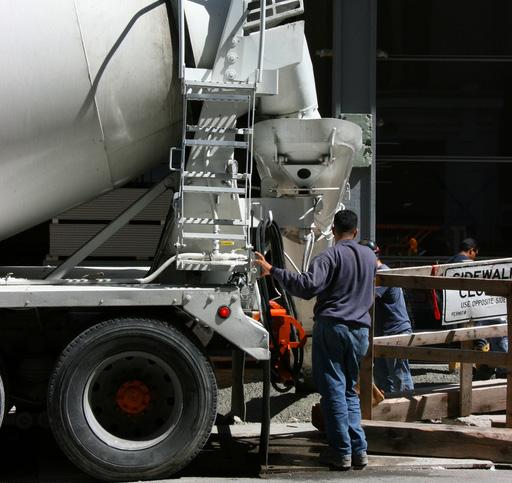
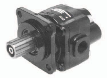
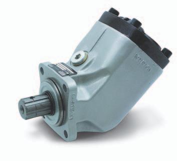
151 Pumps and Motors 3/ Truck Pumps and Motors


152 3/ Truck Pumps and Motors Quick View Pumps and Motors Product Program Fixed Displacement ar F1/F2-Range T1-Range 200 GP- Range GP1 -Range cc/rev 152

153 3/ Truck Pumps and Motors GP and GP1 Pumps Pumps and Motors Light/medium duty pumps Parker s truck gear pumps are ideal for operators of light trucks for their hydraulic power needs. 3 The GP/GP1 series gear pumps are available to suit most applications. They are light and compact, and can be installed in either rear or or side mount configuration thanks to their unique dual port layout. The smaller GP series is built with an extruded aluminum housing for minimum weight. The larger GP1 pumps are built with compact cast iron housings for strength. The gear pumps complement our heavy duty piston pumps and vane pumps. The performance and characteristics are ideal for many light and/or intermittent applications, including the famous Parker reliability, and they are engineered with a long, trouble-free service life. Features Compact and light weight - easy to install even on small vehicles Quiet operation - low noise emissions are important in sensitive areas Robust and reliable - means a long, trouble-free service life uilt for high rpm s - less sensitive to over-speeding i-directional - easy to install Side or rear mount - use the ports on the side or at the rear, whichever is most suitable for the application. 153
154 3/ Truck Pumps and Motors GP and GP1 Pumps Pumps and Motors Specifications Series GP (aluminium body; 3- and 4-bolt) Frame Size 012 Displacement [cm 3/ rev ] 12 Max Continuous Pressure [bar] 250 Max Intermittent Pressure [bar] 270 Max Peak Pressure [bar] 290 Speed [rpm] (at max continous pressure) Min 500 Max 2000 Weight [kg] 4.8 Series GP1 (cast iron body; 3- and 4-bolt) Frame Size Displacement [cm 3/ rev ] Max Continuous Pressure [bar] Max Intermittent Pressure [bar] Max Peak Pressure [bar] Speed [rpm] (at max continous pressure) Min Max Weight [kg]


155 3/ Truck Pumps and Motors GP and GP1 Pumps Pumps and Motors GP olt Frame size 012 Dim. "" 123 Dim. ""


156 3/ Truck Pumps and Motors GP and GP1 Pumps Pumps and Motors GP1-023/-029/-041/ bolt Frame size Dim. "" Dim. "" GP1-023/-029/-041/ bolt Frame size Dim. "" Dim. ""
157 3/ Truck Pumps and Motors GP and GP1 Pumps Pumps and Motors Ordering code Example: GP luminium body 1 Cast iron body Frame size = 008, 011, 014, 016 or = 023, 029, 041, 046, 050, 060 or bolt flange Standard versions luminium 4 bolt Designation Ordering no. GP GP GP GP GP Cast iron 4 bolt Designation Ordering no. GP GP GP GP GP GP GP NOTE: The pump does not include a suction fitting; it must be ordered separately. 157


158 3/ Truck Pumps and Motors F1 Pumps Pumps and Motors Series F1 is a further development of our well known 'truck pump', the F1. The F1 offers many additional values for operators of cargo cranes, hook loaders, skip loaders, forest cranes, concrete mixers and similar truck applications. Series F1 is a very efficient and straight forward pump design with unsurpassed reliability. Its small envelope size gives a simple and inexpensive installation. Features of the F1 are: High selfpriming speeds Operating pressures up to 400 bar High overall efficiency Low noise level Small installation dimensions Low weight... thanks to: 45 bent-axis angle Optimal inlet port geometry in the end cap Single housing design Spherical pistons - high speeds Laminated piston rings - low leakage Positive synchronisation with timing gear Installation above the reservoir level possible Tolerates low temperatures and high temperature shocks Shaft end and mounting flange meet the ISO standard for all sizes 158
![3/ Truck Pumps and Motors F1 Pumps Pumps and Motors Pump cross section Pump cross section Frame size F1-25 41 51 61 81 101 Displacement [cm 3/ rev] 25.6 40.9 51.1 59.5 81.6 102.](/docs-images/72/66941627/images/159-0.jpg "9 Max flow 1) [l/min] Max operating pressure [bar] at 350 bar 67 98 112 131 163 3) 185 3) at 400 bar 56 86 97 113 143 160 continuous 350 350 350 350 350 350 intermittent 400 400 400 400 400 400 Shaft")
159 3/ Truck Pumps and Motors F1 Pumps Pumps and Motors Pump cross section Pump cross section Frame size F Displacement [cm 3/ rev] Max flow 1) [l/min] Max operating pressure [bar] at 350 bar ) 185 3) at 400 bar continuous intermittent Shaft speed [rpm] - short circuited pump (low press.) max speed at 350 bar 2) ) ) at 400 bar 2) ) Torque 1) [Nm] at 350 bar at 400 bar Input power [kw] - continuous intermittent 4) Weight [kg] ) Theoretical Values 2) Valid at an inlet pressure of 1.0 bar (abs.) when operating on mineral oil at a viscosity of 30 mm 2/s (cst). 3) Valid with 21/2" inlet (suction) line. With 2" suction line: F1-81 max 1400 rpm (Q 120 l/min); 4) Max 6 seconds in any one minute. F1-101 max 1000 rpm (Q 120 l/min). NOTE: For noise level information, contact Parker Hannifin 159

160 3/ Truck Pumps and Motors F1 Pumps Pumps and Motors F1-25, -41, -51 and -61 Ordering code Example F1 frame size 25, 41, 51, 61, 81, or 101 Shaft rotation R Right hand L Left hand F R NOTE: The pump does not include a suction fitting; it must be ordered separately. Standard versions Designation Ordering no. F1-25-R F1-25-L F1-41-R F1-41-L F1-51-R F1-51-L F1-61-R F1-61-L Seal Kit
 SP thread (fitting not included) Standard versions Designation Ordering no.")
161 3/ Truck Pumps and Motors F1 Pumps Pumps and Motors F1-81 and -101 Port size F1 frame size Pressure port F1 frame size Pressure port 1) -25 3/4" -41 3/4" -51 3/4" -61 3/4" -81 1" " 1) SP thread (fitting not included) Standard versions Designation Ordering no. F1-81-R F1-81-L F1-101-R F1-101-L

162 3/ Truck Pumps and Motors F1 Motors Pumps and Motors Features: Laminated piston rings - low leakage Positive synchronisation with timing gear Operating pressure up to 250 bar Tolerates low temperatures and high temperature shocks Shaft end and mounting flange meet the ISO standard for all sizes Tolerates high acceleration 162
163 PRT NO. TYPE SER NO. Pump and Motor Division Made in Sweden - 3/ Truck Pumps and Motors F1 Motors Pumps and Motors Motor frame size F1-25-M 41-M 51-M 61-M 81-M 101-M 121-M Displacement [cm 3 /rev] ,5 Max operating pressure [bar] continuous intermittent Max Shaft speed [rpm] - continuous intermittent Torque (theor.) [Nm] at 200 bar at 350 bar Max output power [kw] - continuous intermittent Weight [kg] F M F1 Motor frame size 25, 41, 51, 61, 81, 101 or 121 Port size F1 motor frame size Ø13 (x4) Port size F1-25/41/51/61 3/4" -81/101/121 1" Standard versions Designation Ordering no. F1-25-M F1-41-M F1-51-M F1-61-M F1-81-M F1-101-M F1-121-M NOTE: - Dimensions, in mm, are valid for all frame sizes, except those in brackets [ ] which are valid for F1-25/-41/-51/-61-M only. 98 [104] 114 [98] 113 [SP 3/ 4 "] SP 1" [SP 3 / 4 "] SP 1" Note! Drain line must be mounted. Connection SP 1/2". Maximum drain line pressure is 3 bar [167] 220 [206] M12x24 163
164 3/ Truck Pumps and Motors F2 Twin-flow pumps Pumps and Motors Series F2 is a further development of the twin-flow version of series F1, the very first bent-axis truck pump on the market to feature two entirely independent flows. With a suitable build-up of the hydraulic system, the main advantage with a twin-flow pump is that three different flows can be provided at the same engine speed. The twin-flow pump makes it possible to further optimise the hydraulic system and offers: Less energy consumption Reduced risk of system overheating Lower weight Easier installation Standardised system solutions The twin-flow pump makes it possible to operate two work functions that are independent of each other which leads to higher speed and an increased operating precision. Typical twin-flow applications Large truck loaders Forestry cranes Hook loaders/lift dumpers Tipper/crane combinations Refuse collecting vehicles The pump shaft end/mounting flange meets the ISO standard and suits PTO direct mounting. nother requirement can be a large and a small flow, or two equal flows. ll of these alternatives are possible with the twin-flow pump. The pump can be utilised to provide one flow at high system pressure, and, as soon as the pressure has decreased sufficiently, add the flow from the other circuit. This eliminates the risk of exceeding the PTO power rating and, at the same time, provide an optimal driving. 164
165 3/ Truck Pumps and Motors F2 Twin-flow pumps Pumps and Motors Specifications Frame size F2-42/42 53/53 55/28 70/35 70/70 Displacement [cm 3 /rev] Port Port Max operating pressure [bar] continuous intermittent Max Shaft speed [rpm] (unloaded pump; low pressure) Max selfpriming speed [rpm] Ports 1) 2) and 1) 2) pressurised Port 2) unloaded, pressure in port Input power [kw] Max intermittent 3) Max continuous Weight [kg] Left hand and right hand end caps Outher pressure port () Inlet (suction) port Inner pressure port () Outher pressure port () Inlet (suction) port Inner pressure port () F2 End cap for right hand rotating pump End cap for left hand rotating pump F2 6 Flow vs. shaft speed (theoretical) 1) Valid with 2 1 / 2 " inlet (suction) line; with 2" inlet line: 53/53 and 70/35 max rpm 42/42 and 55/28 max 1400 rpm. (q 120 l/min) 2) Measured at 1.0 bar abs. inlet pressure. Please note: lower inlet pressure affects pump performance. 3) Max 6 seconds in any one minute. Pump speed [rpm] F2-53/53 flow [l/min] Port Port Total (ports + ) Note:42/42 values is 80% of 53/53 values 70/70 values is 130% of 53/53 values F2-70/35 flow [l/min] Port Port Total (ports + ) Note: 55/28 values is 80% of 70/35 values Shaft torque vs. pressure (theoretical) Pressure [bar] F2-53/53 torque [Nm] Port Port Total (ports + ) Note:42/42 values is 80% of 53/53 values 70/70 values is 130% of 53/53 values F2-70/35 torque [Nm] Port Port Total (ports + ) Note: 55/28 values is 80% of 70/35 values NOTE: The pump does not include a suction fitting; it must be ordered separately 165
166 3/ Truck Pumps and Motors F2 Twin-flow pumps Pumps and Motors Outlet (pressure) port (SP 3/4") Inlet (suction) port F Right hand rotation Left hand rotation pprox. center of gravity /-0 Spline 8x32x36 (ISO 14/DIN 5462) Ø33 +0/-0.1 Ø80 Ø34.9 (+0/-0.013) 148 M12x24 Ordering code Example: Frame size [cm 3 /rev] 42/42 53/53 55/28 70/35 70/70 Direction of rotation L Left hand R Right hand F2-53/53 - L Standard versions Designation Ordering no. F2-42/42-R F2-42/42-L F2-53/53-R F2-53/53-L F2-55/28-R F2-55/28-L F2-70/35-R F2-70/35-L F2-70/70-R F2-70/70-L NOTE: - efore start-up, tighten the inspection port plug to Nm. - To change the direction of rotation, the end cap must be replaced. NOTE: The pump does not include a suction fitting; it must be ordered separately. 166
 or to a coupling independent PTO (e.g. an engine PTO) which meets ISO standard 7653-1985.")
167 3/ Truck Pumps and Motors VP1 pump Pumps and Motors The VP1 is a variable displacement pump for truck applications. It can be close-coupled to a gearbox PTO (power take-off) or to a coupling independent PTO (e.g. an engine PTO) which meets ISO standard n application that makes full use of all the features of the VP1 is truck cranes with a load sensing system. The complex systems of refuse collection vehicles and sewage trucks as well as various combinations of tippers, cranes, snow ploughs, and salt/sand spreaders can also be greatly simplified and optimised with the VP1 pump. The VP1 provides the hydraulic system with the correct amount of fluid at precisely the right moment, effectively reducing energy consumption and heat generation. This means a smoother and quieter hydraulic system with much reduced impact on the environment. The VP1 is highly efficient and extremely light. It is reliable, economical and easy to install. The four frame sizes, VP1-045, -075, -095, -110 and -130 have small installation dimensions. Design Large angle - compact design The pump design permits a large angle, 20, between piston and slipper shoe/swashplate, providing compactness and small outer dimensions. Tandem coupling The through-shaft on VP1-45/-75 permits tandem coupling of an additional pump, such as a series F1 fixed displacement pump. The VP1 is suitable for all load sensing systems, regardless of make. Features Variable displacement Low noise level High power-to-weight ratio Compact and light Highly efficient Sturdy design Withstands low temperatures Can be close coupled and tandem mounted. (tandem coupling only for VP1-45/-75) Retainer plate The retainer plate (refer to the cutaway illustration in chapter 8) is of a heavy duty design which makes the pump withstand high shaft speeds and fast speed changes.(e. g. engine PTO). Long life The VP1 is designed for trucks with hydraulic load sensing systems. It is sturdy, yet simple, with few moving parts. The result is a reliable pump with long service life. 167
168 3/ Truck Pumps and Motors VP1 pump T Pumps and Motors Specifications Frame size VP Displacement [cm 3 /rev] Max operating pressure [bar] continuous intermittent 1) Mass moment of inertia J [kgm 2 ] Selfpriming speed 2) [rpm] 2" suction line, max /2" suction line, max " suction line, max Max Speed unloaded [rpm] (in bypass mode, no flow) Control type Shaft end spline LS DIN 5462 Mounting flange Weight (with control) [kg] ISO ) Max 6 seconds in any one minute. 2) t an inlet pressure of 1.0 bar (abs.) with mineral oil at a viscosity of 30 mm 2 /s (cst). VP1-045/-075 cross section 1. Inlet port 2. Top purge plug 3. Return spring 4. Control 5. Setting piston (one of two) 6. Swash plate 7. earing shell 8. End cover 9. Spline (for mounting an auxiliary pump) 10. earing sleeve 11. Hold-down plunger 12. Valve plate 13. Cylinder barrel 14. arrel housing 15. ottom purge plug 16. Piston with piston shoe 17. Retainer plate 18. earing housing 19. Roller bearing 20. Shaft seals with carrier 21. Input shaft
169 3/ Truck Pumps and Motors VP1 pump Pumps and Motors VP1-045 and max (R.H. rotation) 73 max (L.H. rotation) 107 max 46 min Top purge plug 73 min Ø Ø80 (+0/-0.013)I 71 max max 20 max 132 max Centre of gravity ottom purge plug Spline 8x32x36 (ISO 14/DIN 5462) Inlet gauge port; SP 1/4" Outlet (pressure) port SP 1" (L.H. rotation) Control drain port T (SP 1/4") Outlet gauge port SP 1/4" (L.H. rot n) Inlet (suction) port; SP 1 1/4" 43 LS T Outlet gauge port SP 1/4" (R.H. rot n) 43 M12x Outlet (pressure) port SP 1" (R.H. rotation) Load sensing port LS (SP 1/4") VP1_inst_G.eps IMPORTNT The control is not drained through the pump case. n external line must be installed between the con-trol drain port 'T' and the reservoir. NOTE: The pump does not include a suction fitting; it must be ordered separately. See chapter
 Dampening nozzle (L.H.")
170 3/ Truck Pumps and Motors VP1 pump Pumps and Motors LS valve block VP1-045/075 Load sensing port (SP 1/4") Control drain port (SP 1/4") Signal pressure limiter adjustment (1 turn = 55 bar) O-ring (x6) Dampening nozzle (L.H. rotating pump) LS T (To setting piston 1) (To setting piston 2) Topp view Differential pressure ( p) adjustment (1 turn = 5 bar) Pressure relief cartridge ottom view Dampening nozzle (R.H. rotating pump) Setting spring Cross section Fig. 2. LS valve block. Valve spool Section LS_block_G.eps Leif./ Through-shaft coupling VP1-045/075 The VP1 pump has a through-shaft which means that an additional pump, such as a fixed displacement F1, can be installed in tandem with the VP1 by means of an adaptor kit (fig. 3). NOTE: The bending moment caused by the weight of a tandem assembly normally exceeds that allowed by the PTO. To prevent damage, the auxiliary pump should be supported by a bracket attached to the gearbox; it must not be fastened to the truck chassis. Likewise, when the tandem assembly is installed on a separate bracket and driven by a cardan shaft, the auxiliary pump should have a support attached to the pump bracket. Fig. 3. daptor kit (P/N ) for tandem coupling. IMPORTNT Contact Parker Hannifin for additional information when considering tandem mounting a second VP1 pump. 170
171 T T 3/ Truck Pumps and Motors VP1 pump Pumps and Motors VP1-095/-110/-130 cross section 1. Shaft seal 2. Roller bearing 3. Upper purge plug 4. earing shell 5. Setting screw (pressure relief valve) 6. Setting bushing (standby pressure) 7. Control 8. Piston with piston shoe 9. Upper setting piston (control pressure) 10. Needle bearing 11. Shaft 12. Drain hole, shaft seals 13. Lower purge plug 14. earing housing 15. Swash plate 16. Retainer plate 17. Lower setting piston (pump pressure) 18. Cylinder barrel 19. Valve plate 20. arrel housing LS control (for VP1-095/-110/-130) lternative LS port To be connected directly to the oil tank (SP 1 / 4 ") 1. Signal pressure cut-off (1 turn = 140 bar) 2. Counter nut, screw 1 T LS LS Load sensing port (SP 1 / 4 ") 3. asic valve setting (factory set) DO NOT TOUCH! LS control cross section. VP1_095_control_section.ai 4. Standby pressure Leif setting,./ factory set at 25 bar; (1 turn = 17 bar) 5. Counter nut, bushing 4 LS control ports. NOTE: lways run a function, after adjusting the standby pressure or the max pressure setting, before you read the value. Item Wrench / dimension 1 Hex Head Wrench / 4 mm 2 Wrench / 13 mm 3 DO NOT TOUCH 4 Wrench / 27 mm 5 Wrench / 27 mm 171
172 3/ Truck Pumps and Motors VP1 pump Pumps and Motors VP1-095/-110/ Gauge port M (SP 1/ 4 ") (system pressure) Upper purge plug; SP 1 / 4 " (not tightened when delivered) 12 Rotation arrow (R.H. rotation shown) Ø80 (+0/-0.013) 101 Ø12.5 (x4) 104 Ø Washer (covering the shaft seal drain hole) Centre of gravity Lower purge plug; SP 1 / 4 " NOTE: The pump does not include a suction fitting; it must be ordered separately. See chapter 11. Drain port T (SP 1 / 4 ") lternative LS port IMPORTNT! The control is not drained through the pump case; an external drain line must be installed from control port T and, directly, to the oil tank. Gauge port M (SP 1 / 4 ") (system pressure) Load sensing port LS (SP 1/ 4 ") M12 (24 deep) Spline 8x32x36 (ISO 14/DIN 5462) Suction port 2 x M12 depth 17 to attach support device Pressure port (SP 1") x M12 depth 17 to attach support device Pressure port (SP 1") M8, 19 deep (x4); on P.C. dia Suction port View Left hand rotating pump View Right VP1_095_install.ai hand rotating pump 172
173 3/ Truck Pumps and Motors VP1 pump Ordering information Example: VP L Frame size 045, 075, 095, 110 or 130 Direction of rotation L Left hand R Right hand NOTE: The VP1 is uni-directional. Consequently, the desired direction of rotation must be stated when ordering. VP1 in load sensing systems When installed in a load sensing system, the VP1 sup-plies the correct amount of fl ow required by the various work functions currently engaged. This means that energy consumption and heat genera-tion are minimised and much reduced in comparison with a fi xed displacement pump used in the same sys-tem. Diagram 1 shows the required power (fl ow times pressure) in a constant fl ow system with a fi xed displacement pump. Standard model numbers Pumps and Motors Designation Ordering no. Ordering no. No Paint lack Paint VP1-045-R VP1-045-L VP1-075-R VP1-075-L VP1-095-R VP1-095-L VP1-110-R VP1-110-L VP1-130-R VP1-130-L Diagram 2 shows the sharply reduced power requirement in a load sensing system with a variable displacement pump such as the VP1. In both cases the pump pressure is slightly higher than what is required by the heaviest load ( Load 2 ) but the VP1, because of the much smaller fl ow being delivered, needs only the power indicated by the shaded area Load power. In a constant flow system, on the other hand, excess fluid is shunted to tank and the corresponding power, Wasted power (shown in diagram 1), is a heat loss. Pressure Corner power Pressure Corner power p Max p Max Load 1 Load 2 Load 3 Wasted power p Load Load power Q Load 1-3 Q Max Flow Diagram 1. Constant fl ow system with a fixed displacement pump. Systems comparison System Constant flow Load-sensing Pump Fixed displ. VP1 variable displ. Pump adjustments Pressure only Pressure and flow Load* Some influence Some influence Energy consumption High Low Heat generation High Low p Load Load 1 Load 2 Load power Wasted power Load 3 Q Load 1-3 Q Max Flow Diagram 2. Constant fl ow system with a variable displacement pump (e.g. VP1). * Simultaneous operation of loads with non-equal fl ows and pressures; refer to the above diagrams
174 3/ Truck Pumps and Motors VP1 pump LS load sensing control function Refer to corresponding hydraulic schematic below. selected 'opening' of the directional control valve spool corresponds to a certain flow to the work function. This flow, in turn, creates a pressure differential over the spool and, consequently, also a p between the pump outlet and the LS port. When the differential pressure decreases (e.g. the direc-tional valve is opened further) the p also decreases and the LS valve spool moves to the left. The pressure to the setting pistons then decreases and the pump dis-placement increases. The increase in pump displacement stops when the p finally reaches the setting (e.g. 25 bar) and the forces acting on the valve spool are equal. If there is no LS signal pressure (e.g. when the directional valve is in the neutral, no-flow position) the pump only delivers sufficient flow to maintain the standby pres-sure as determined by the p setting. LS control adjustments Pressure limiter Pump size Factory setting [bar] VP1-045/ VP1-095/110/ LS load sensing valve Pump size Factory setting [bar] Max pressure intermittent [bar] Min pressure [bar] Pumps and Motors Max pressure [bar] VP1-045/ VP1-095/110/ The factory setting, and the standard orifice sizes shown in the corresponding schematic below, will usually provide an acceptable directional valve characteristic as well as system stability. For additional information, contact Parker Hannifin. Hydraulic schematic for VP1-45/75 To work function Hydraulic schematic for VP1-095/-110/-130 To work function T P 1 T P 1 LS P 2 LS P Min 7 7 Min 5 Setting pistons Max Setting piston Max T T 1. Directional, load sensing control valve 2. Load signal orifice (1.0 mm; fixed) 3. Gauge port 4. Signal pressure limiter adjustment 5. System pressure dampening nozzle (2.0 mm) 6. Return line nozzle (0.6 mm) 7. Standby ( p) pressure adjustment 8. System pressure dampening orifice (fixed) 9. leed-off nozzle (0.6 mm). 1.Directional, load sensing control valve 2. Load signal orifice (0.8 mm) 3. Gauge port 4. Signal pressure limiter adjustment 5. Standby ( p) pressure adjustment 6. System pressure dampening orifice (fixed) 7. leed-off nozzle (1.2 mm) 174
175 3/ Truck Pumps and Motors VP1 pump L General information The L boost unit simplifies the building of closed or semi-closed hydrostatic transmissions. Main features are: Replaces conventional charge pump and corresponding valves in many applications llows pump speeds above normal selfpriming speed Suitable for system flow rates to 400 l/min Includes filter Simple construction - no moving/wear parts Cost-effective installation Small tank size Helps in building a low-cost hydrostatic transmission. Description In a closed circuit hydrostatic transmission, a charge pump is normally included with the main pump, providing make-up fluid which replaces pump and motor volumetric losses. It also maintains sufficient pump inlet pressure to avoid cavitation. The L boost unit replaces the charge pump in many applications, when the following conditions are met: - - The max-to-min pump flow ratio does not exceed 2:1 System pressure changes gradually without frequent and pronounced pressure peaks - The line length between pump and boost unit is relatively short. There are two basic sizes of the L boost unit: - L 4 (to 160 l/min pump flow) - L 6 (to 400 l/min). The main part of the unit is an aluminium housing with a built-in nozzle and an injector; refer to the cross section to the right. When fluid flows from the motor outlet port through the unit and to the pump inlet port, the increased fluid velocity between the nozzle and injector creates a low pres-sure zone causing additional fluid to be drawn from tank into the main circuit. lso, pressure increases after the injector, allowing the pump to be operated at speeds higher than the selfpriming speed. The boost pressure increases with flow. The housing includes ports that should be connected to the pump and motor drain ports respectively. n additional bleed-off nozzle diverts approx. 10% of the main flow through the cartridge filter before being directed to the tank. For more information please see our technical catalogue L boost unit HY /UK T Typical applications: Fan drives Propeller drives Generator drives Pump drives. Pumps and Motors Oil cooling n oil cooler is usually required in the hydraulic system, in order to remove the heat that is generated in the main circuit. full-flow oil cooler should be installed in the return line between the motor and the boost unit. To pump inlet L boost unit cross section. 1 Injector From Nozzle tank 1. Pump 2. Motor 3. oost unit (with injector and nozzle 4. Filter cartridge To filter From filter 3 4 to tank oost unit installation From motor outlet leed-off nozzle 2 5. Pressure relief valve 6. Full-flow filter (when required 7. Reservoir 9 175
176 3/ Truck Pumps and Motors Suction fittings Pumps and Motors for series F1, F2 and T1 pumps also VP1-095, -110 and -130 suction fitting consists of a straight, 45, 90 or 135 suction fitting, clamps, cap screws and O-ring. Suctions fittings for VP1-045/075 Straight suction fittings for F1, F2, T1, VP1-095/-110/-130 Suction fitting Cap screw Hold-down clamp Ordering no. mm mm C dia. mm (in.) ) (1 1 / 2 ") ) (2") ) (2 1 / 2 ") ) (3") Straight fitting C O-ring 45 suction fittings for F1, F2, T1, VP1-095/-110/ Ordering no. mm mm C dia. mm (in.) ) (1 1 / 4 ") ) (1 1 / 2 ") ) (2") ) (2 1 / 2 ") ) (3") fitting C C suction fittings for F1, F2, T1, VP1-095/-110/ fitting Ordering no. mm mm C dia. mm (in.) ) (1 1 / 2 ") ) (2") ) (2 1 / 2 ") ) (3") 145 suction fitting for F1, F2, T1, VP1-095/-110/ Ordering no. mm mm C dia. mm (in.) (2") 145 fitting C 1) Recommended for frame size F ) Recommended for frame size F1-41,-51,-61,-81, ) (3 clamps and 3 screws) Spare parts dditional Hold-down-clamp kit consists of: hold-down-clamp cap screw and O-ring Ordering no dditional Hold-down-clamp kit for mounting on PV Ordering no NOTE: suction fitting must be ordered separately (not included with the pump)
177 3/ Truck Pumps and Motors Suction fittings Pumps and Motors Suitable suction adapters for F1 with SP port treads 45 adapter Ø Ordering no. mm mm C dia. mm (in.) " 2" / 4 " 2" / 4 " 2 1 / 2 " 18 * SP threads Ø 13 C 90 adapter Ordering no. mm mm C dia. mm (in.) " 2" / 4 " 2" 18 * SP threads Ø Fitting kits for VP1-045 and -075 pumps Pressure fitting Ø Nipplar_ny.eps C Kits with 45 suction fitting Pump size. Ordering no. C 1 ØC 2 VP1-045/ SP 3 / 4 " 2" VP1-045/075* SP 1" 2 1 / 2 " * bove 100 l/min C 2 C 1 45 adjustable suction fitting NOTE: suction fitting must be ordered separately (not included with the pump). 177


178 3/ Truck Pumps and Motors pplication Market Pumps and Motors GP/GP1, F1/F2 Truck Pumps & Motors pplication Market Markets Forestry Construction Mining Material Handling Recycling Military pplications Knuckle oom Loader, Cranes, Mowers / Cutters Off-Highway Trucks, Fan Drives, Hookloader, Tipper Dump Trucks Truck Mounted Cranes, Lift Trucks, Tow truck, Small Crane Vaccum Truck Systems, Refuse Trucks - SL, Rear Loaders Fan Drives 178

179 3/ Truck Pumps and Motors Literature Pumps and Motors Ref. Catalogue : HY /UK 179

180 4/ ppendix Sizing Link : 180
Genuine Metaris Gear Product Technical Catalog. Pumps & Components - MH Series Bearing & Bushing Style
 Genuine Metaris Gear Product Technical Catalog Pumps & Components - MH Series Bearing & Bushing Style www.metaris.com MH365 Series Bushing Pump Features Metaris Bushing Pumps & Motors are available in
Z SERIES. Z40 Technical Specifications. Hydraulic Pump/Motor Product Group
 Z SERIES Hydraulic Pump/Motor Product Group Z40 Technical Specifications Bushing Design Replacement parts for industry common pump/motor series. Assemblies are built to match your replacement or to meet
Z SERIES. Z32 Technical Specifications. Hydraulic Pump/Motor Product Group
 Z SERIES Hydraulic Pump/Motor Product Group Z32 Technical Specifications Bushing Design Replacement parts for industry common pump/motor series. Assemblies are built to match your replacement or to meet
Z SERIES. Z34 Technical Specifications. Hydraulic Pump/Motor Product Group
 Z SERIES Hydraulic Pump/Motor Product Group Z34 Technical Specifications Bushing Design Replacement parts for industry common pump/motor series. Assemblies are built to match your replacement or to meet
Gear Pumps / Motors. Series PGP / PGM Fixed Displacement Pumps, Cast-Iron and Aluminium Designs
 Gear Pumps / Motors Series PGP / PGM Fixed Displacement Pumps, Cast-Iron and Aluminium Designs Table of contents Heavy-duty Pumps and Motors Series PGP, PGM Contents Page Series 500 Aluminium Table of
Veljan Gear Pumps. 'B' Series Features:
 '' Series Features: Self-priming pumps Heavy duty sleeve bushing design in a small frame size Displacements from 9.8cc/rev to 39.9cc/rev Working pressures up to bar Speeds up to rpm Flows up to 10.5gpm
Gear Pumps. Series PGP Fixed Displacement Pumps, Cast-Iron Designs
 Gear Pumps Series PGP Fixed Displacement Pumps, Cast-Iron Designs aerospace climate control electromechanical filtration fluid & gas handling hydraulics pneumatics process control sealing & shielding Table
CONTENT Axial Piston Motors and Pumps Fixed Displacement. Technical Specification Guide...2. Hydraulic motor MAP Hydraulic motor MAP50...
 CONTENT CONTENT Aial Piston Motors and Pumps Fied Displacement PAGE Technical Specification Guide...2 Hydraulic motor...6 Hydraulic motor MAP5...1 Hydraulic motor MAP1...2 MAP5 Hydraulic pump PAP5...29
Gear Pumps / Motors Series PGP / PGM Cast-Iron and Aluminium Designs
 Gear Pumps / Motors Series PGP / PGM Cast-Iron and Aluminium Designs Catalogue HY11-3252/UK January 2002 Heavy-duty pumps and motors Series PGP, PGM Note This document and other information from, its subsidiaries,
Veljan Gear Pumps. E' Series Features:-
 E' Series Features:- Heavy duty sleeve bushing design in a small frame size Displacements from 43.5cc/rev to 146.5cc/rev Working pressures up to 240bar Speeds up to 3500rpm Flows up to 38.7gpm High strength
Gear Housing Widths 1.00" 1.25" 1.50" 1.75" 2.00" 2.25" 2.50" Gear Housing Widths / Flow Rate [ VGP - D Series ]
![Gear Housing Widths 1.00 1.25 1.50 1.75 2.00 2.25 2.50 Gear Housing Widths / Flow Rate [ VGP - D Series ]](/thumbs/76/74105930.jpg "Gear Housing Widths 1.00 1.25 1.50 1.75 2.00 2.25 2.50 Gear Housing Widths / Flow Rate [ VGP - D Series ]") 'D' Series Features:- Heavy duty sleeve bushing design in a small frame size Displacements from 20.6cc/rev to 104.2cc/rev Working pressures up to 240bar Speeds up to 3500rpm Flows up to 27.5gpm High strength
'D' Series Features:- Heavy duty sleeve bushing design in a small frame size Displacements from 20.6cc/rev to 104.2cc/rev Working pressures up to 240bar Speeds up to 3500rpm Flows up to 27.5gpm High strength
Heavy-duty cast-iron pumps and motors Series PGP, PGM 300. Characteristics. Parker Series 300
 Characteristics Parker Series 300 Design - Three-piece cast-iron construction - Low-friction bushing design - Heavy-duty application - Single, multiple, piggyback, and thru-drive assemblies Description
Z SERIES Z22 TECHNICAL SPECIFICATIONS. Hydraulic Pump/Motor Product Group Roller Bearing Design
 Z SERIES Hydraulic Pump/Motor Product Group Roller Bearing Design Z22 TECHNICAL SPECIFICATIONS Replacement parts for industry common pump/motor series. Assemblies are built to match your replacement or
Heavy Duty Hydrostatic Transmissions
 Heavy Duty Hydrostatic Transmissions Features and Benefits Typical Applications Construction Transit Mixer Road Roller Paver Motor Grader Loader Dozer Material Handling & Utility Crane Sweeper Lift Truck
Gear Pump Division. Coding
 Gear Pump Division Coding October 28, 2014 Commercial Roller Bearing Gear Pumps Major Components PGP050B278BYOL20-98DAF12-1 1 3 1 2 3 4 5 6 7 2 5 6 1) Shaft End Cover 2) Port End Cover 3) Gear Housing
SMB5.0A(CA) - SMB440A(CA)
 - SMB440A(CA)") SMB5.0A(CA) - SMB440A(CA) SURFACE MOUNT TRANSIENT VOLAGE SUPPESSOR DIODE VOLTAGE RANGE: 5.0-440 V POWER: 600Wa t t s Features Mechanical Data Glass Passivated Die Construction Uni- and Bi-Directional Versions
SMB5.0A(CA) - SMB440A(CA) SURFACE MOUNT TRANSIENT VOLAGE SUPPESSOR DIODE VOLTAGE RANGE: 5.0-440 V POWER: 600Wa t t s Features Mechanical Data Glass Passivated Die Construction Uni- and Bi-Directional Versions
Gear Pumps / Motors. Series PGP / PGM Fixed Displacement Pumps, Cast-Iron and Aluminium Designs
 Gear Pumps / Motors Series PGP / PGM Fixed Displacement Pumps, Cast-Iron and Aluminium Designs Contents Contents Page PGP/PGM500 Characteristics... 3 PGP502 Ordering... 4 PGP502 Performance curves... 5
Direct solenoid and solenoid pilot operated valves
 Direct solenoid and solenoid pilot operated valves Individual mounting Series Inline Manual operator Solenoid 4-way pilot with balanced poppet Air return 33 34 36 3 37 38 5 67 69 44 46 4 47 48P SERIES
Direct solenoid and solenoid pilot operated valves
 Direct solenoid and solenoid pilot operated valves Individual mounting Series Inline Oval shaped armature Encapsulated coil Push pin onded balanced poppet Return spring Manifold mounting Stacking plug-in
MCC omponents Itasca Street Chatsworth
 omponents 21201 Itasca Street Chatsworth!"# $%!"# SMBJ5.0 THRU SMBJ170CA Features For surface mount applications in order to optimize board space Low profile package Fast response time: typical less than
SECTION A-A TPA AND ALIGNMENT PLATE IN PRE-SEATED POSITION
 THIS RWING IS UNPULISHE. OPYRIGHT Y TE ONNETIVITY RELESE FOR PULITION LL RIGHTS RESERVE. P LTR ESRIPTION TE WN PV REVISE PER EO00 MR JMS H REVISE PER EO00 PR JMS H QTY. REQUIRE INEX INEX INEX LIST OF PRTS
International standard flanges acc.to SAE, ISO, DIN, GOST. [bar] 0,5 (7.3 PSI)
![International standard flanges acc.to SAE, ISO, DIN, GOST. [bar] 0,5 (7.3 PSI)](/thumbs/96/129251394.jpg "International standard flanges acc.to SAE, ISO, DIN, GOST. [bar] 0,5 (7.3 PSI)") Gear Pump High Performance Version GP3 up to cm 3 (6. inch 3 ) p max 32 bar (46 PSI) Speed from 35 to 32 RPM Technical Features Operating pressure 29 bar, Peak pressure 32 bar High-strength quality aluminum
Gear Pump High Performance Version GP3 up to cm 3 (6. inch 3 ) p max 32 bar (46 PSI) Speed from 35 to 32 RPM Technical Features Operating pressure 29 bar, Peak pressure 32 bar High-strength quality aluminum
Gear Motors. Series PGM Fixed Displacement Motors, Aluminium Designs
 Gear Motors Series PGM Fixed Displacement Motors, Aluminium Designs aerospace climate control electromechanical filtration fluid & gas handling hydraulics pneumatics process control sealing & shielding
SAMYANG ELECTRONICS SMBJ SMBJ440CA TRANSIENT VOLTAGE SUPPRESSOR. Features. Mechanical Characteristics
 SAM YANG SAMYANG ELECTRONICS TRANSIENT VOLTAGE SUPPRESSOR BREAKDOWN VOLTAGE: 5.0 --- 440 V PEAK PULSE POWER: 600 W SMB (DO-214AA) Features Working peak reverse voltage range 5.0V to 440V. power dissipation
International standard flanges acc.to SAE, ISO, DIN, GOST. [bar] 0,5 (7.3 PSI)
![International standard flanges acc.to SAE, ISO, DIN, GOST. [bar] 0,5 (7.3 PSI)](/thumbs/76/74105994.jpg "International standard flanges acc.to SAE, ISO, DIN, GOST. [bar] 0,5 (7.3 PSI)") Gear Pump High Performance Version GP3 up to 1 cm 3 (6.1 inch 3 ) p max 3 (46 PSI) Speed from 35 to 32 RPM Technical Features Operating pressure 29 bar, Peak pressure 3 High-strength quality aluminum alloys
Gear Pump High Performance Version GP3 up to 1 cm 3 (6.1 inch 3 ) p max 3 (46 PSI) Speed from 35 to 32 RPM Technical Features Operating pressure 29 bar, Peak pressure 3 High-strength quality aluminum alloys
SMA6J5.0A(CA) - SMA6J440A(CA)
 - SMA6J440A(CA)") SMA6J5.0A(CA) - SMA6J440A(CA) SURFACE MOUNT TRANSIENT VOLAGE SUPPESSOR DIODE VOLTAGE RANGE: 5.0-440 V POWER: 600Wa t t s Features Glass Passivated Die Construction Uni- and Bi-Directional Versions Available
SMA6J5.0A(CA) - SMA6J440A(CA) SURFACE MOUNT TRANSIENT VOLAGE SUPPESSOR DIODE VOLTAGE RANGE: 5.0-440 V POWER: 600Wa t t s Features Glass Passivated Die Construction Uni- and Bi-Directional Versions Available
PRODUCT GUIDE LANDSCAPE LIGHTING. fxl.com. A Hunter Industries Company
 PRODUCT GUIDE LANDSCAPE LIGHTING A Hunter Industries Company fxl.com FINISHES Metals Powder coat Standard Powder coat Specialty s AB on copper AB on brass AT on copper AT on brass CU BS SS NP BZ DG WI
HYDRAULIC OIL PUMPS AND MOTORS PRODUCT CATALOG. Hybel - Hydraulic Oil Pumps and Motors
 HYDRAULIC OIL PUMPS AND MOTORS PRODUCT CATALOG Hybel Hydraulic Oil Pumps and Motors HYDRAULIC OIL PUMPS AND MOTORS Contents CONTENTS About us.... 04 Products Line.... 06 Configure your product.... 08 Aluminibeta
PRODUCT GUIDE LANDSCAPE LIGHTING
 PRODUCT GUIDE LANDSCAPE LIGHTING North America fxl.com FINISHES Metals AB Antique Bronze on Powder coat Standard AB Antique Bronze on Brass AT Antique Tumbled on AT Antique Tumbled on Brass CU BS Natural
YMSY. Advanced design in disc distribution flow,which can automatically compensate in operating with high volume efficiency and long life.
 The series motors adapts an advanced ROLLER gear set designed with disc distribution flow and high pressure. This motor series uses the ROTOR gear type manufactured with most advanced technology and quality
Global Gear Products. Brochure. SAE A-Aluminum (Group 2)
") Global Gear Products Brochure SAE A-Aluminum (Group 2) High Efficiency, Low Noise Applications for Eaton Gear Products Turf care Agriculture tractors and harvesters Lift trucks Skidsteer loaders Fan drive
Global Gear Products Brochure SAE A-Aluminum (Group 2) High Efficiency, Low Noise Applications for Eaton Gear Products Turf care Agriculture tractors and harvesters Lift trucks Skidsteer loaders Fan drive
MINING FORESTRY MOBILE TRUCK AGRICULTURE MATERIAL HANDLING OPTIMUM
 MINING FORESTRY MOBILE TRUCK AGRICULTURE MATERIAL HANDLING OPTIMUM Muncie Power Products OPTIMUM Series gear pumps/motors offer premier performance for a wide variety of applications across several industries.
* * 124 SERIES * * * * ENGINEERING CODEBOOK * *
 * * 124 SERIES * * * * ENGINEERING CODEBOOK * * THROUGH THE USE OF THIS CATALOG ALL THE COMPONENT PARTS OF ANY PERMCO PUMP OR MOTOR CAN BE DETERMINED EXCLUDING FASTENERS. THIS CODE BOOK IS FOR THE 124
HYDRO-PNEUMATICS. 1) Hydro-Pneumatic Tool De-Clamp Cylinders PCS Series ) Hydro-Pneumatic Intensifiers for Machining Centers... 1.
 Hydro-Pneumatic Tool De-Clamp Cylinders PCS Series ) Hydro-Pneumatic Intensifiers for Machining Centers... 1.") HYDRO-PNEUMATICS 1) Hydro-Pneumatic Tool De-Clamp Cylinders PCS Series... 1.310 2) Hydro-Pneumatic Intensifiers for Machining Centers... 1.330 HYDRAULIC CYLINDERS 1) LH7 Series... 2.110/1 Std. Mounting
HYDRO-PNEUMATICS 1) Hydro-Pneumatic Tool De-Clamp Cylinders PCS Series... 1.310 2) Hydro-Pneumatic Intensifiers for Machining Centers... 1.330 HYDRAULIC CYLINDERS 1) LH7 Series... 2.110/1 Std. Mounting
Direct solenoid and solenoid pilot operated valves
 Direct solenoid and solenoid pilot operated valves SIZE 26 mm Individual mounting Valve only No base non plug-in Conform to ISO 15407/1 Manifold mounting Valve only No base non plug-in Conform to ISO 15407/1
Oildyne. Miniature Piston Pumps 5 Piston Design. Pressures to 276 bar (4000 psi) Displacements from.156cc/rev to.865cc/rev (.01 to.
 Displacements from.156cc/rev to.865cc/rev (.01 to.") Oildyne 5 Piston Design Pressures to 276 bar ( psi) Displacements from.156cc/rev to.865cc/rev (.1 to.5 in 3 /rev) 29 Features Pumping Efficiencies to 9% Allow You to Effectively Use.156 to.865 cc Flow
Oildyne 5 Piston Design Pressures to 276 bar ( psi) Displacements from.156cc/rev to.865cc/rev (.1 to.5 in 3 /rev) 29 Features Pumping Efficiencies to 9% Allow You to Effectively Use.156 to.865 cc Flow
Hydraulic Motor/Pump Series F11/F12 zp12
 Hydraulic Motor/Pump zp12 Fixed Displacement zp11 Catalogue HY17-8249/US March 2004 Conversion factors 1 kg... 2.20 lb 1 N... 0.225 lbf 1 Nm... 0.738 lbf ft 1 bar...14.5 psi 1 l...0.264 US gallon 1 cm
Hydraulic Motor/Pump. Series F11/F12 Fixed Displacement. parker.com/pmde
 Hydraulic Motor/Pump Series F11/F12 Fixed Displacement parker.com/pmde Series F11/F12 Torque (M) M = D x p x η hm 63 [Nm] Conversion factors 1 kg... 2.20 lb 1 N... 0.225 lbf 1 Nm... 0.738 lbf ft 1 bar...14.5
MCC SMBJ5.0 THRU SMBJ440CA. Features. Transient Voltage Suppressor 5.0 to 440 Volts 600 Watt. Mechanical Data
 omponents 20736 Marilla Street Chatsworth!"# $%!"# SMBJ5.0 THRU SMBJ440CA Features For surface mount applications in order to optimize board space Low profile package Fast response time: typical less than
STANDARDISED MOUNTINGS
 STNDRDISED MOUNTINGS for PES / PLS cylinders conforming to ISO 15552-FNOR-DIN standard Series 434 MOUNTINGS CONFORMING TO ISO 15552 - FNOR NF ISO 15552 - DIN ISO 15552 STNDRDS B C pplications duty Construction
ENGINEERING DATA. High Torque, Low Speed Motors H, S, 2000, 6000, and 10,000 Series. w w w. F l u i D y n e F P. c o m
 ENGINEERING DATA High Torque, Low Speed Motors H, S, 2000, 6000, and 10,000 Series Interchangeable with: Charlynn White Ross Parker Danfoss w w w. INDEX Cross Reference Guide...2 Introduction...3 H-Series...4
LPRA/182000/M, ISO cylinder Magnetic piston, double acting
 > > Ø 32... 125 mm > > High performance, stability and reliability > > M/50 switches can be mounted flush with the profile > > Cylinders and mountings conform to ISO 15552 (ISO 6431, VDM 24562 and NFE
D SERIES HYDRAULIC PUMP
 uk distributor for D SERIES HYDRAULIC PUMP quality products for mechanical & fluid power jbj Techniques Limited, www.jbj.co.uk Introduction to Concentric D Series Hydraulic Pumps Concentric offers one
Hydraulic Motor/Pump. Series F11/F12 Fixed Displacement
 Hydraulic Motor/Pump Series F11/F12 Fixed Displacement Series F11/F12 Torque (M) M = D x p x η hm 63 [Nm] Conversion factors 1 kg... 2.20 lb 1 N... 0.225 lbf 1 Nm... 0.738 lbf ft 1 bar...14.5 psi 1 l...0.264
Hydraulic Motor/Pump. Series F11/F12 Fixed Displacement. parker.com/pmde
 Hydraulic Motor/Pump Series F11/F12 Fixed Displacement parker.com/pmde Series F11/F12 Torque (M) M = D x p x η hm 63 [Nm] Conversion factors 1 kg... 2.20 lb 1 N... 0.225 lbf 1 Nm... 0.738 lbf ft 1 bar...14.5
Motors & Pumps- Hydraulic Pumps, Motors & Power Units
 - Hydraulic umps, Motors & ower Units - Rapid Response...12-1 12-6 Hydraulic umps - Check Valves...12-7 Hydraulic umps - ower Units...12-8 12-9 12MOTORS & UMS Hydraulic umps - Vane ump...12-10 Motors...12-11
INSTRUMENT PANEL CLUSTERS
 INSTRUMENT PANEL CLUSTERS NOT BUYING AT THIS TIME REVISED ##### PART # MAKE APPLICATION 6/18/2018 PRICE 56045618 CHRY IPC 40.00 56045679 CHRY IPC 40.00 56051103 CHRY IPC 40.00 56049833 AC,AD CHRY IPC 40.00
Hydraulic Motor/Pump. Series F11/F12 Fixed Displacement. parker.com/pmde
 Hydraulic Motor/Pump Series F11/F12 Fixed Displacement parker.com/pmde Series F11/F12 Torque (M) M = D x p x η hm 63 [Nm] Conversion factors 1 kg... 2.20 lb 1 N... 0.225 lbf 1 Nm... 0.738 lbf ft 1 bar...14.5
HYDRAULIC HEAVY DUTY
 Catalog #HHD-16 12/16 HYDRAULIC HEAVY DUTY Series HHD 3000 PSI RATED 10-25-16 WARNING IMPROPER SELECTION, IMPROPER USE OR FAILURE OF THE PRODUCTS AND/OR SYSTEMS DESCRIBED HEREIN CAN CAUSE PROPERTY DAMAGE,
W1200 SERIES HYDRAULIC PUMP
 W1200 SERIES HYDRAULIC PUMP Concentric A Innovation in Hydraulics Table of Contents Description Page Number W1200 Product Specifications and Performance Information -----------------------------------------------------------------------3
Aluminium tube and profile
 > Series 63 cylinders CATALOGUE > 206 Series 63 cylinders - Aluminium tube and profile New Single and double-acting, magnetic, cushioned Versions: standard, low friction, high and low temperatures ø 32,
Heavy Duty Actuators CONTROLS. Pneumatic Actuators for Quarter-Turn Valves and Dampers Torques to 1,600,000 in. lbs. Double Acting and Spring Return
 CONTROLS Division of A-T Controls Heavy Duty Actuators Pneumatic Actuators for Quarter-Turn Valves and Dampers Torques to,600,000 in. lbs. Double Acting and Spring Return THD S E R I E S The Triac line
Hydraulic Pump Division. Product Range - HY /HPD/US. aerospace climate control electromechanical filtration fluid & gas handling
 aerospace climate control electromechanical filtration fluid & gas handling hydraulics pneumatics process control sealing & shielding Hydraulic Pump Division Product Range - HY28-2673-01/HPD/US WRNING
PVE 19 & 21 Piston Pumps
 Engineering PVE 19 & 21 Piston Pumps Pressures to 3500 psi For Mobile and Industrial Use Same Day Shipments Rated for 2400 rpm > Speeds to 2400 rpm www.fluidynefp.com Table of Contents Introduction...2
Series 63 ISO cylinders
 Series 63 ISO 15552 cylinders New versions Single and double-acting, magnetic, cushioned ø 32, 40, 50, 63, 80, 100, 125 mm In compliance with the ISO 15552 standard Weight reduced by 25% Low noise More
Direct solenoid and solenoid pilot operated valves
 Direct solenoid and solenoid pilot operated valves Individual mounting Series Inline Oval shaped armature Encapsulated coil Push pin Manifold mounting Stacking Manifold base plug-in Manifold base plug-in
Performance Information Series PVP 100/140 Pressure Compensated, Variable Volume, Piston Pumps
 Catalog HY13-155-2/US Technical Information Series PVP 1/14 Performance Information Series PVP 1/14 Compensated, Variable Volume, Piston Pumps Features High Strength Cast-Iron Housing for Reliability and
Whisper Pumps VPV Vane Pumps
 Whisper Pumps VPV Vane Pumps Contents Whisper Vane Pump Catalog 3 Contents Introduction 4 Benefits 4 Specifications 5 Ordering details 8 Performance characteristics 12 VPV 16 to PSI (21 Bar) 12 VPV 25
Cylinders Series 61 - Aluminium profile
 CATALOGUE > Release 8. Cylinders Series 6 - Aluminium profile MOVEMENT > Cylinders Series 6 Single, double-acting, magnetic, cushioned ø 32, 40, 50, 63, 80, 00, 25 (ISO 5552)» ISO 5552 (corresponding to
Series PHP10 Variable Volume, Piston Pumps
 Catalog HY13-1553-1/N,EU Series PHP1 Series PHP1 Variable Volume, Piston Pumps Bulletin 2-18/US 123 Catalog HY13-1553-1/N,EU Series PHP1 Performance Information Series PHP1 Pressure Compensated, Variable
1500 Series. Roller Bearing Gear Pumps and Motors (Bi-Rotational) High Performance Features: Hydreco
 High Performance Features: Hydreco") Roller Bearing Gear Pumps and Motors (Bi-Rotational) High Performance Features: The 1500K Series Pump/Motor utilizes the many design and application features of the widely accepted HYDRECO Series modern
Roller Bearing Gear Pumps and Motors (Bi-Rotational) High Performance Features: The 1500K Series Pump/Motor utilizes the many design and application features of the widely accepted HYDRECO Series modern
Pneumatic cylinders, piston-ø mm Double acting with magnetic piston DIN ISO 15552
 Pneumatic cylinders, piston-ø 32 100 mm Double acting with magnetic piston DIN ISO 15552 Technical data for series SL 050 450 Order code SL-032-0250-050 Series Piston-Ø Stroke length (mm) Type of cylinder
Z10 & Z16 TECHNICAL SPECIFICATIONS
 Z SERIES Hydraulic Pump/Motor Product Group Roller Bearing Design Z10 & Z16 TECHNICAL SPECIFICATIONS Replacement parts for industry common pump/motor series. Assemblies are built to match your replacement
International standard flanges acc.to SAE, ISO, DIN, GOST. [bar] 0,5 (7.3 PSI)
![International standard flanges acc.to SAE, ISO, DIN, GOST. [bar] 0,5 (7.3 PSI)](/thumbs/76/74105951.jpg "International standard flanges acc.to SAE, ISO, DIN, GOST. [bar] 0,5 (7.3 PSI)") Gear Pump High Performance Version GP up to 31 cm 3 (1.89 inch 3 ) p max 3 bar ( PSI) Speed from to RPM Technical Features Operating pressure 8 bar, Peak pressure 3 bar High-strength quality aluminum alloys
Gear Pump High Performance Version GP up to 31 cm 3 (1.89 inch 3 ) p max 3 bar ( PSI) Speed from to RPM Technical Features Operating pressure 8 bar, Peak pressure 3 bar High-strength quality aluminum alloys
Group 1 Gear Pumps Technical Information General Information
 General Information OVERVIEW The Sauer-Danfoss Group is a range of peak performance fixed-displacement gear pumps. Constructed of a high-strength extruded aluminum body with aluminum cover and flange,
Catalog HY /NA. Catalog HY /NA. Parker Hannifin Corporation Hydraulic Pump Division Marysville, Ohio USA
 Catalog HY28-6/NA PV, PVT Series Piston Pumps Variable Volume Catalog HY28-6/NA 1 Catalog HY28-6/NA Notes Series PV 2 Catalog HY28-6/NA Introduction Series PV Quick Reference Data Chart Pump Delivery Approx.
W1500 SERIES HYDRAULIC PUMP
 W1500 SERIES HYDRAULIC PUMP Concentric AB Innovation in Hydraulics PRESSURE (P1) 276 BAR (4000 PSI) (P2) 300 BAR (4400 PSI) SPEED 3300 RPM Min. 500 RPM at 4000 PSI (276 BAR) Continuous EFFICIENCY Overall
PRA/822000/M, PRA/ Smoothline cylinder Magnetic or non-magnetic piston, double acting
 P/822000/M, P/822000 Smoothline cylinder > 32... 00 mm > Cylinder and mounting conform to ISO 5552 > eed or solid state switches can be mounted flush with the profile barrel > lternative air ports as standard
Gear Pumps/Motors Series PGP/PGM 500
 Gear Pumps/Motors Series PGP/PGM 500 Express Delivery Program Note This document and other information from Parker Hannifin GmbH, its subsidiaries, sales offices and authorized distributors provide product
Solutions. We Manufacture. H y d r a u l i c s. Eaton Medium Duty Piston Pump. h y d r a u l i c s
 H y d r a u l i c s ydraulics Eaton Medium Duty Piston Pump h y d r a u l i c s Model 70122, 70422, 70423, and 70523 or -Flow Compensated Piston Pumps We Manufacture April 1997 Solutions S o l u t i o
Series 1 Model Codes
 Eaton Heavy Duty Hydrostatic Transmissions No. 11-06-0866su EN 1000 (Supplement Sheet TO 11-866) Series 1 Model s Models 33 through 76 Hydrostatic Transmissions Series 1 Variable Pump Model The following
Aluminium profile. TANDEM: Double thrust and traction forces. LOW FRICTION: Friction force reduced by over 40%
 CATALOGUE > Release 8.7 > Series 6 cylinders Series 6 cylinders - Aluminium profile Single and double-acting, magnetic, cushioned Standard, low friction, low temperatures and tandem versions ø 32, 40,
Eaton. Revised June, Heavy Duty Hydrostatic Transmissions. l r. Models 33 through 76 Hydrostatic Transmissions. We Manufacture.
 s Eaton Revised June, 1997 c Heavy Duty Hydrostatic Transmissions h i y d l ydraulics r a u u l c a i r s y d Models 33 through 76 Hydrostatic Transmissions We Manufacture Solutions H S o l u t i o n s
Hydraulic Motor & Brake
 SERIES 500-501 - 510-511 - 520-521 - 530-531 - 50-51 - MEDIUM DUTY Hydraulic Motor & rake RE RE (ll Series) For Medium Duty pplications Overview series descriptions RE Series motors offer the perfect compromise
AP212HP Cast Iron Gear Pumps
 Cast Iron Gear Pumps Standard and Low Noise series Reference: 200-P-991236-EN-01 Issue: 09.2016 1/56 Contents Page 1 General information... 5 1.1 External gear pumps components... 6 1.2 Technical data...
Variable Displacement Piston Pumps. Performance Information. Features. Specifications. Controls. Schematic Symbol (Basic Pump) Weight and Package Size
 Weight and Package Size") Catalog HY13-1552-2/US Technical Information Series PVC65 Performance Information Series PVC65 Compensated, Variable Volume, Piston Pump Features High Strength Cast-Iron Housing uilt-in Supercharger High
Catalog HY13-1552-2/US Technical Information Series PVC65 Performance Information Series PVC65 Compensated, Variable Volume, Piston Pump Features High Strength Cast-Iron Housing uilt-in Supercharger High
Performance Information Series PVP 41/48 Pressure Compensated, Variable Volume, Piston Pumps
 Catalog HY13-1553-1/N,EU Technical Information Performance Information Compensated, Variable Volume, Piston Pumps Features High Strength Cast-Iron Housing for Reliability and Quiet Operation Vickers Porting
Single and double-acting, magnetic, cushioned Standard, low friction, low temperatures and tandem versions ø 32, 40, 50, 63, 80, 100, 125mm
 CATALOGUE > Release 8.8 > Series 60 cylinders Series 60 cylinders Single and double-acting, magnetic, cushioned Standard, low friction, low temperatures and tandem versions ø 32, 40, 50, 63, 80, 00, 25mm»»
Single and double-acting, magnetic, cushioned Standard, low friction and low temperature versions ø 32, 40, 50, 63, 80, 100, 125mm
 CATALOGUE > Release 8.6 > Series 60 cylinders Series 60 cylinders New version Single and double-acting, magnetic, cushioned Standard, low friction and low temperature versions ø 32, 40, 50, 63, 80, 00,
AS/ASH SERIES ALUMINUM PNEUMATIC AND HYDRAULIC CYLINDERS... 6
 AS/ASH SERIES ALUMINUM PNEUMATIC AND HYDRAULIC CYLINDERS............. 6 Section 6 8 ORDERING INFORMATION For Rod End Dimensions see back cover foldout... Basic Cylinder No Mount.0" to 4.00" For pressure
HEAVY DUTY PNEUMATIC CYLINDERS
 HEAVY DUTY PNEUMATIC CYLINDES Features: Conforms to ISO:30 standard. Double Acting, with adj. cushioning at both ends. Sizes: Ø, Ø, Ø, Ø, Ø, Ø0, Ø1, Ø0, Ø0 & Ø0. : Other bore sizes on request Seamless
10/97 N Our policy is one of continued research and development. We therefore reserve the right
 ISO Cylinders Magnetic Piston Double Acting Ø 10 to 25 mm Magnetic piston as standard Conforming to ISO 6432 Corrosion resistance Buffer and adjustable cushioned models Supplied complete with nose mounting
Series 6PF Positioning Feedback cylinders 1/ Double-acting low friction, magnetic ø 50, 63, 80, 100, 125 mm
 CATALOGUE > Release 8.8 > Series 6PF cylinders Series 6PF Positioning Feedback cylinders Double-acting low friction, magnetic ø 50, 63, 80, 00, 25 mm»» In compliance with ISO 5552 standards and with the
Bore ø 32, 40, 50, 63, 80, 100, 125 Ports 32 = 1/8, 40/50 = 1/4, 63/80 = 3/8, 100/125 = 1/2
 6 S E R I E S Cylinders Series 6 Catalog 2006 Single, double acting, magnetic (DIN/ISO 643) Bore: ø 32, 40, 50, 63, 80, 00, 25 cushioned [ /4, 9/6, 2, 2 /2, 3 /8, 4, 5 inch approximations] The Series 6
Hydraulic Motor/Pump Series F11/F12
 Hydraulic Motor/Pump Fixed Displacement Catalogue HY30-8249/UK October 2006 Basic formulas for hydraulic motors Flow (q) D x n q = 1000 x η [l/min] v Torque (M) M = D x p x η hm 63 Power (P) q x p x η
M/1000, Heavy Duty Cylinders Double Acting
 > > Ø 2 to 12 (50 to 305 mm) > > Extremely rugged heavy duty construction - ideal for use in the most arduous conditions. > > Large range of bore sizes - ideal for a wide variety of industrial applications.
Mobile Cylinder Div. Standard Build Series. Catalog HY /US Rev C
 Mobile Cylinder Div. Standard Build Series Catalog HY18-0014/US Rev C WARNING - USER RESPONSIBILITY FAILURE OR IMPROPER SELECTION OR IMPROPER USE OF THE PRODUCTS DESCRIBED HEREIN OR RELATED ITEMS CAN CAUSE
P1X Series. Compact Rodless Air Cylinders Contents
 Compact DL RC P1Z P1X OSP-P Contents Features and Benefits... 130 Ordering Information... 131 Specifications, Weights and Forces... 132 Technical Data... 133-136 Sensor Adapter Bracket... 137 Basic Dimensions...
Grade boundaries June 2018 exams. GCSE Reformed (subjects which use the 9 to 1 grade scale)
") Version 1.0 Grade boundaries June 2018 exams GCSE Reformed (subjects which use the 9 to 1 grade scale) This document presents grade boundaries for the new reformed GCSEs which use the 9 to 1 grade scale.
Version 1.0 Grade boundaries June 2018 exams GCSE Reformed (subjects which use the 9 to 1 grade scale) This document presents grade boundaries for the new reformed GCSEs which use the 9 to 1 grade scale.
Hydraulics. VPV Vane Pumps. Whisper Pumps. Automation Technology
 Hydraulics VPV Vane Pumps Whisper Pumps Automation Technology VPV Vane Pump 1 Table of Contents Introduction 2 Benefits 2 Specifications 3 Ordering Guide 6 Performance Characteristics 9 Performance Characteristics
Model Model Model Model Back to Back. Medium Pressure Piston Pump Variable Displacement Closed Circuit
 Medium Pressure Piston Pump Variable Displacement Closed Circuit Model 76 2.3 cm 3 /r [.24 in 3 /r] 23.6 cm 3 /r [.44 in 3 /r] Model 736 4.6 cm 3 /r [2.48 in 3 /r] 49.2 cm 3 /r [3. in 3 /r] Model 724 4.6
Series AM/MM/WM Mill Type Cylinders
 ET AH To order this part, call Lifco Hydraulics USA Toll Free at -00-- S S ZE* SS* SW (TYP) FB THRU, () PLACES TE UF WA / EE P* ØE EE P* CD 00 M CW S Series AM/MM/WM Mill Type Cylinders Table of Contents
MOVICONTROL. Single and Double Fixed Vane Pumps SERIES V10, V20, 25V/VQ, 35V/VQ, 45V/VQ.
 Single and Double Fixed Vane Pumps SERIES V10, V20, 25V/VQ, 35V/VQ, 45V/VQ www.movicontrol.com.br V10/V20 Series Features Balanced vane type pumps are excellent for medium- to low-pressure mobile and industrial
Vickers. Piston Motors. Inline Piston Motors. Fixed and Variable Displacement. Revised 5/99 691
 Vickers Piston Motors Inline Piston Motors Fixed and Variable Displacement Revised 5/99 691 Table of Contents Introduction........................................................................................
À cylindrée fixe Gamme MAP 50
 pplications Moteur à pistons axiaux M+S À cylindrée fixe Gamme MP Cylindrée de 6,6 à cm Vitesse de rotation maxi de tmin Couple maxi danm Puissance maxi 6 Kw ébit d huile maxi : 9 lmin Charge axiale maxi
GM25 Motor Dimensional Information
 GM25 Series Birotational Hydraulic Motors GM25 Series hydraulic motors are designed for low noise, high efficiency birotational operation. Cast iron construction insures reliability and strength. A number
8000 Series Open Loop Pumps
 Table of Contents Features and enefits 2 Specifications 3 Shaft Torque Ratings 4 Pressure Pick-ups 4 Controls Pressure Compensator 5 Dual Pressure Compensator 5 Soft Start Pressure Compensator 6 Load Sensing
THD. Series. Heavy Duty Actuators. Pneumatic Actuators for Quarter-Turn Valves and Dampers CONTROLS. Torques to 1,600,000 In-lbs
 CONTROLS Division of A-T Controls, Inc. THD Series Heavy Duty Actuators Pneumatic Actuators for Quarter-Turn Valves and Dampers Torques to 1,600,000 In-lbs Double Acting and Spring Return Symmetric and
CFR Series. Power Inductors OUTLINE FEATURES APPLICATIONS SPECIFICATIONS MITSUMI
 CFR Series Coils, Transformers OUTLINE Power inductors for preventing the diffusion of noises generated from power circuits and suppressing noise components coming through the power lines. ø8.7 ø11 max.
Gear Pumps and Motors Technical Catalog. Series 26 Pumps Series 26 Motors Series L2 Pumps
 Gear Pumps and Motors Technical Catalog Series 26 Pumps Series 26 Motors Series L2 Pumps Table of Contents Series 26 Pumps Features...5 General Specifications and Performance Data...7 Performance Data