Emergency pull-wire, Belt-alignment, Slack-wire switches. Automation. Catalogue // SYSTEMATIC CONTROL SWITCHGEAR
|
|
|
- Margery Ford
- 6 years ago
- Views:
Transcription

1 Automation Emergency pull-wire, Belt-alignment, Slack-wire switches // SYSTEMATIC CONTROL SWITCHGEAR Catalogue
2
3 4 The Company PRODUCTS 6 Emergency pull-wire switches 12 Selection table Emergency pull-wire switches 13 Spring pre-stress and travel limitation One-side actuation 14 Series ZS Series ZS Series ZS Series ZS Series ZS Series ZS 80 Two-side actuation 34 Series ZS 73 S 38 Series ZS 75 S 42 Series ZS 91 S 44 Belt-alignment switches 48 Series ES 61 SR 49 Series ES 98 SR 50 Series ZS 73 SR 52 Series ZS 75 SR 54 Series ZS 91 SR 56 Pull-wire switches 60 Selection table pull-wire switches 62 Series ES 95 Z 64 Series ES 51 Z 66 Series ES/EM 41 Z 70 Series ES/EM 61 Z 72 Series ZS Series ZS Slack-wire switches 78 Series ES/EM 41 DB 80 Appendix 80 Accessories for emergency pull-wire and pull-wire switches 82 Explanation of symbols


4


5 // SAFE SWITCHGEAR FOR DEMANDING AND CRITICAL APPLICATIONS Wireless Automation Extreme Meditec»Safe switchgear for demanding and critical applications«. True to this motto, steute has been providing its customers with innovative, practical and durable switchgear solutions for over 50 years. When our customers are successful, so are we. Because we always focus on our customers, our company has grown steadily and sustain ably over the last decades. Steute is committed to continuing this growth in close cooperation with our customers. We are situated in East Westphalia, a key region for machine building and electrical goods manufacturing. It is home to qualified specialists committed to developing and manufacturing innovative products. It is also the location of renowned universities, research and educational institutions to which we maintain healthy contacts. Markets are no longer restricted by national borders. This is why our products are developed and tested for extreme conditions all over the world. We take care to ensure that our products are always certified according to the latest international standards. In every industrial or emerging nation in the world, steute has access to qualified specialists who can guarantee competent support and a quick service. As a medium-sized company we are able to react with speed to customer wishes and market trends. We are continually developing innovative products and using new technologies as we consistently open up new fields of application for our switchgear. steute is currently active in four different business fields, producing switchgear, sensors and control units for use in industry and in medical equipment: Wireless Cable free switchgear and sensors for use in machinery and process plants. These industrial-strength wireless switches communicate with higher level control systems via reliable radio transmission.»energy harvesting«can play a major role in these products. Automation Standard and customised switchgear for machinery and process plants. Tried and tested electromechanical and non-contact technologies for classical applications in industrial automation and process control always with a view to the latest global requirements. Extreme Switchgear and sensors for use in extreme environments or under extreme conditions. Certified products for use in hazardous areas worldwide (e. g. ATEX, IECEx, GOST). Meditec A comprehensive range of standard and customised foot and hand controls for medical devices, meeting the highest ergonomic and availability requirements. Produced in accordance with the certified EN ISO quality management system for medical products. The following information provides an overview of our standard range of switchgear for complex and demanding applications. We will be happy to provide you with any additional information you require. If you cannot find the solution for your application: just get in touch. We have already helped numerous customers by developing»tailormade«switchgear for their individual needs. Marc Stanesby Managing Director steute Schaltgeräte GmbH & Co. KG
6 6

7 Emergency pull-wire switches // Selection table Emergency pull-wire switches from page 12 // Pre-stress and travel limitation from page 13 One-side actuation // Series ZS 70 from page 14 // Series ZS 71 from page 16 // Series ZS 73 from page 20 // Series ZS 75 from page 24 // Series ZS 441 from page 28 // Series ZS 80 from page 32 Two-side actuation // Series ZS 73 S from page 34 // Series ZS 75 S from page 38 // Series ZS 91 S from page 42 7 ZS 80
8 8
9 Emergency pull-wire switches Application Emergency pull-wire switches are of great importance for the man-machine interface in the area of industrial applications. They are, for example, applied on transport and conveyor systems. After manual actuation, work and functional processes are initiated or switched off. When the new harmonised European standard EN ISO concerning functional aspects and design guidelines for emergency-stop devices has come into effect, new requirements must have to be met by these command devices. All emergency pull-wire switches described in this chapter meet the requirements of this standard. Design and mode of operation On emergency pull-wire switches the emergency-stop command can be initiated from any point along the pull-wire. They have a positive linkage between the NC contacts and the pull-wire. The emergency pull-wire switches are brought into the operational condition by pre-tensioning the pull-wire, i.e. the NC contacts are then closed and the NO contacts are open. All devices are equipped with wire-breakage detection. In the chapter accessories of the appendix the required accessories for installation are presented. Emergency pull-wire switches without mechanical latching VD or VS do not conform to the EN ISO It is possible to meet the requirements of this standard by suitable measurement of the circuitry and control technology. There are devices with one- and two-side actuation. The wire length, the number of contacts and the mounting position, in the middle or on one side of the system, are the main features when selecting an emergency pull-wire switch. All emergency pull-wire switches bear the CE mark according to the Machinery Directive 2006/42/EC. Application Mounting at head level Mounting at hand level Mounting at foot level Mounting at hazardous inrunning nips 9 Mounting at conveyor-belts Complete fencing
10 Emergency pull-wire switches // Technical information 10 Function principle All emergency pull-wire switches from steute are provided with a wire-break detection so that the wire must with be mounted with a defined pre-tension force. This value of the pre-tension force vaies depending on the different devices. The appropriate value can be found on the data sheet of the emergency pull-wire switch. With an incorrect mounting cannot be taken in operation, i. e. an unlocking is not possible. By vertically pulling the pull-wire the switching function is carried out. The actuating force is exclusively depending on the spring rate of the reset spring. There are emergency pull-wire switches with one-side and two-side actuatiuon, see drawings below. Emergency pull-wire switches with two-side actuation must always be mounted with two compensation springs. According to EN the maximum values of the actuating force F = 200 N and of the actuating travel s = 400 mm must not be exceeded on vertical actuation of the emergency pull-wire switch. In addition, the pull-wire must withstand the 10 times higher vertical pulling force that is required in order to generate the emergency-stop signal. Interrelation of actuating travel / distance wire support Maximum pull-wire length The maximum pull-wire length is mainly limited by two basic conditions. On the one hand by the maximum admissible actuating travel s of 400 mm and on the other hand by the thermal change in length of the pull-wire with a fluctuating ambient temperature that may not lead to an undesired actuation of the switch. Because the first basic condition requires a preferably low and the second requires a preferably high elasticity of the system it is necessary to optimise such systems in respect to both basic conditions depending on the operational conditions. In addition, it must be checked if the actuating force F of 200 N is adhered. Application of compensation springs / Travel limitation Compensation springs are applied to compensate thermal changes in lengths of the pull-wire and therefore allow for higher pullwire lengths. In general the following is valid: - Soft compensation spring with a low spring rate can compensate higher thermal changes in length. - Though on pull-wire actuation soft compensation springs have a high expansion behaviour and therefore earlier reach the limit of the maximum actuating travel s = 400 mm. Thus the expansion behaviour limitates the maximum pull-wire length at a constant temperature range or the temperature range at a constant pull-wire length. - The dimensioning of the compensation spring is determined by the reset spring of the switches (Value of the pre-tension force and Mounting of one-side actuation Compensation spring with travel limitation Mounting of two-side actuation
11 Emergency pull-wire switches // Technical information Examples of other compensation springs variants Distance of wire support The actuating travel required to vertically actuate the switch results from the sum of the spring travels of the switch, pull-wire and where required compensation spring as well as the distance of the wire supports x [m]. This means a larger actuating travel is required with a larger distance of the wire supports when actuating the pullwire in order to achieve the same actuating distance. Securing a safe switching at a constant pull-wire length the distance of the wire supports must be reduced in order to aim for a wider temperature range. spring rate of the rest spring ), the pull-wire length (length and elasticitiy of the pull-wire) and the maximum actuatimng travel of s = 400 mm. - With two-side actuation a travel limitation must be installed, see drawing left page, in order to prevent overstretching of the tension spring - Before mounting the pull-wire, the red PVC sheath must be removed from the the pull-wire in the clamping range of the pull-wire! An overstress of the compensation spring is in general prevented by a travel limitation. In practice either additional travel limitations are applied or self-protecting compensation springs are used. Additional travel limitations made of catch-ropes are critical when the function relevant length of the travel limitation is set but have a clear advantage in cost in comparison to compensation springs. Wire thimble deformation Type of pull-wire The expansion behaviouer of the pull-wire is determined b the type of wire. Besides elastic elongation permanent elongations can occur when actuating the pull-wire. Under certain conditions higher pre-tension forces can lead to relaxation processes (temporal pre-tension loss). Statistical spread of the manufacturing process also have an effect on the expansion behaviour. Therefore it is urgently recommended at least for longer pull-wire lengths to apply pull-wires from steute. These are much tougher and thus optimised for such applications. Pull-wires from other manufacturers often lengthen gradually because of the creep characteristics of the plastic core (relaxation). If so, it is necessary to regularly check the pull-wire tension and if required to retension the pull-wire. The appropriate security note in the mounting and wiring instructions and the standard application of a tensioner are the prerequisite for a safe function. Mounting notes - After fitting the wire, pull strongly on it several times, as the pull-wire and the wire thimble will deform. - Subsequently, retense the wire using the wire clamp, eye-bolt or tensioner. - In order to guarantee safe operation, observe the enclosed mounting and wiring instructions. - According to EN ISO 13850, pulleys may only be mounted such that the complete length of the pull-wire can be observed. 11
12 Selection table Emergency pull-wire switches // Series // Maximum pull-wire length ZS 70, on page 14 - Thermoplastic enclosure 10 m - One-side actuation - 2 contacts ZS 71, on page 16 - Metal enclosure 35 m - One-side actuation - 3 contacts 12 ZS 73, on page 20 and 34 - Metal enclosure 130 m 2 x 100 m - One-side actuation: ZS 73 - two-side actuation: ZS 73 S - 2 contacts ZS 75, on page 24 and 38 - Metal enclosure 130 m 2 x 100 m - One-side actuation: ZS 75 - Two-side actuation: ZS 75 S - 4 contacts ZS 441, on page 28 - Metal enclosure 60 m - One-side actuation - 2 contacts ZS 80, on page 32 - Metal enclosure 100 m - One-side actuation - 4 contacts ZS 91 S, on page 42 - Thermoplastic enclosure 2 x 100 m - Two-side actuation - 6 contacts
13 Emergency pull-wire switches // Pre-stress and actuating forces Notes - The values are indicated for an ambient temperature of 20 C at the stated wire length. - The linear expansion of the wire due to strain and deformation of the wire thimble is not considered. - The actuating forces are only approximate values, due to the spring forces being subject to tolerances. Actuating forces and travel between supports Emergency pull- Wire length betw. Pre-stress Actuating Actuating Wire Ordering wire switch supports x [m] force [N] travel s [cm] force F [N] length [m] index ZS 70 2, <10 ZS ZS / N / N ZS 73 S x ZS / N / N ZS 75 S x ZS /150N ZS ZS 91 S 3 <40 <80 2 x 100
 - Wire pull and breakage detection // ZS 70 Technical data 14 Standards EN 60947-5-1, EN 60947-5-5, EN ISO 13850, EN ISO 13849-1 Enclosure")
14 Emergency pull-wire switches, one-side actuation // Series ZS 70 - Thermoplastic enclosure - 2 contacts - Mounting details to EN Small design - Wire length up to 10 m - Push button release - Available without unlocking mechanism (per EN ) - Wire pull and breakage detection // ZS 70 Technical data 14 Standards EN , EN , EN ISO 13850, EN ISO Enclosure glass-fibre reinforced, shock-proof thermoplastic, ultramid Cover glassfibre reinforced, shock-proof thermoplastic, ultramid Degree of protection IP 67 to IEC/EN Contact material silver Switching elements change-over contact with double break or 2 NC contacts Switching system snap action, positive break NC contacts A Connection screw connection terminals Cable cross section max. 2.5 mm 2 (incl. conductor ferrules) Cable entry 1 x M20 x 1.5 B 10d (10 % load) T M max. 20 years U imp 6 kv U i 400 V I the 6 A Utilisation category AC-15 I e /U e 6 A/400 VAC Max. fuse rating 6 A gg/gn fuse Ambient temperature 25 C +70 ºC Mech. life > operations Max. wire length 10 m Features wire pull and breakage detection Approvals H d a e Contact variants: switch travel/contacts Snap action 1 NC/1 NO contact ZS 70 1Ö/1S VD Ordering details ZS 70 1Ö/1S VD VD push button release 1 NC/1 NO contact (2Ö) Series Emergency pull-wire switch 2 NC contacts ZS 70 2Ö VD At 2.5 m distance intermediate wire supports are required. One wire thimble is provided. Details related to pre-stress and actuating forces are indicated on page 13.
15 Emergency pull-wire switches, one-side actuation // Series ZS 70, mounting Legend 1 Cable tensioner system TS Eye bolt M8 x 70 with nut Wire clamp Wire thimble Pull-wire per metre // Mounting without compensation spring l [m] ΔT [K] 15
16 Emergency pull-wire switches, one-side actuation // Series ZS 71 - Metal enclosure - 3 contacts - Small design - Wire length up to 35 m - Release by push button or key possible - Available without unlocking mechanism (per EN ) - Wire pull and breakage detection - Ex version available - IP 69K version available, see section»extreme«// ZS 71 Technical data ø10 ø5,3 10 Standards EN , EN , EN ISO 13850, EN ISO Enclosure aluminium die-cast, enamel finish Cover glass-fibre reinforced, shock-proof thermoplastic, ultramid Degree of protection ZS 71 VD, ZS 71 WVD and ZS 71 NA: IP 67; ZS 71 VS and ZS 71 WVS: IP 54 to IEC/EN Contact material silver Switching elements 2 NC/1 NO contacts with double break Switching system snap action, positive break NC contacts A Connection screw connection terminals Cable cross section max. 2.5 mm 2 (incl. conductor ferrules) Cable entry 2 x M20 x 1.5 B 10d (10 % load) T M max. 20 years U imp 6 kv U i 400 V I the 2 A Utilisation category AC-15 I e /U e 2 A/250 VAC Max. fuse rating 2 A gg/gn-fuse Ambient temperature 25 C +70 ºC Mech. life > operations Indicator lamp as option Max. wire length 35 m Features wire pull and breakage detection Approvals H d a e ,5 ø ,5 52 M20x1,5 42,5 11 Contact variants: switch travel/contacts Snap action 2 NC/1 NO contact ZS 71 2Ö/1S Ordering details ZS 71 2Ö/1S WVD-A/100 N-G Indicator lamp (app.) 100 N pre-stress force A position indicator (NA emergency-stop button) VD push button release (VS key release on request) W watertight collar 2 NC/1 NO contact Series Emergency pull-wire switch At 3 m distance intermediate wire supports are required. One wire thimble is provided. Details related to pre-stress and actuating forces are indicated on page 13.
17 Emergency pull-wire switches, one-side actuation // Series ZS 71, mounting Legend 1 Cable tensioner system TS Eye bolt M8 x 70 with nut Wire clamp Wire thimble Compensation spring ZS N Pull-wire per metre // Mounting without compensation spring 6 l [m] ΔT [K] // Mounting with compensation spring 17 6 l [m] ΔT [K] // Mounting with 2 emergency pull-wire switches 6 l [m] ΔT [K]
18 Emergency pull-wire switches, one-side actuation // Series ZS 71, variants - Indicator lamps for various voltages are indicated in chapter accessories in the appendix - Indicator lamp position in the left side cable entry // Push-button release VD ø10 10 Push-button release ZS 71 2Ö/1S VD/100 N ø5, ,5 ø , M20x1,5 42,5 11 // Watertight collar W - Watertight collar for protection against penetration of dirt Watertight collar/push-button release ZS 71 2Ö/1S WVD/100 N // Key release VS Key release ZS 71 2Ö/1S VS/100 N ,5 ø25 61 ø10 ø5,3 16,5 ø25 Key release/watertight collar ZS 71 2Ö/1S WVS/100 N M20x1,5 42,5 47,5
19 // Position indicator A Position indicator/push-button release ZS 71 2Ö/1S VD-A/100 N Position indicator/push-button release/collar ZS 71 2Ö/1S WVD-A/100 N Position indicator/key release ZS 71 2Ö/1S VS-A / 100 N Position indicator/key release/collar ZS 71 2Ö/1S WVS-A/100 N // Emergency-stop push-button NA ø Position indicator A not available for variant ZS 71 NA - Version with emergency-stop push button for direct and fast actuation at the switch ,5 27, ø5,3 Ø24 50 Ø25 Emergency-stop push-button ZS 71 2Ö/1S VD-NA/100 N ZS 71 2Ö/1S WVD-NA/100 N M20x1, ,5
 - Release by push button or key possible - Wire pull and breakage detection - Ex version available // ZS 73 Technical data 20 105 30 14,5 27 56,5 25 6,5 48")
20 Emergency pull-wire switches, one-side actuation // Series ZS 73 - Metal enclosure - 2 contacts - Wire length up to 130 m - 2 various spring force variants (actuating forces) - Available without unlocking mechanism (per EN ) - Release by push button or key possible - Wire pull and breakage detection - Ex version available // ZS 73 Technical data , ,5 25 6,5 48 M16x1,5 167,5 162,5 ø , Standards EN , EN , EN ISO 13850, EN ISO Enclosure aluminium die-cast, enamel finish; ZS 73 NIRO: aluminium die-cast, hard-coated and enamelled Cover glass-fibre reinforced, shock-proof thermoplastic, ultramid Degree of protection ZS 73 WVD: IP 65; ZS 73 VD, ZS 73 VS and ZS 73 WVS: IP 54 to IEC/EN Contact material silver Switching elements change-over contact with double break or 2 NC contacts Switching system snap action, positive break NC contacts A Connection screw connection terminals Cable cross section max. 2.5 mm 2 (incl. conductor ferrules) Cable entry 1 x M16 x 1.5 B 10d (10 % load) T M max. 20 years U imp 6 kv U i 400 V I the 6 A Utilisation category AC-15 I e /U e 6 A/400 VAC Max. fuse rating 6 A gg/gn fuse Ambient temperature 25 C +70 ºC Mech. life > operations Indicator lamp as option Max. wire length 130 m Features wire pull and breakage detection Approvals H d a e Contact variants: switch travel/contacts Snap action 1 NC/1 NO contact ZS 73 1Ö/1S 2 NC contacts ZS 73 2Ö Ordering details ZS 73 1Ö/1S WVD-NIRO/ N-G Indicator lamp (app.) N pre-stress force ( N) NIRO pull-wire unit VD push button release (VS key release) W watertight collar 1 NC/1 NO contact (2Ö) Series Emergency pull-wire switch At 5 m distance intermediate wire supports are required. One wire thimble is provided. Details related to pre-stress and actuating forces are indicated on page 13.
21 Emergency pull-wire switches, one-side actuation // Series ZS 73, mounting Legend 1 Cable tensioner system TS Eye bolt M8 x 70 with nut Wire clamp Wire thimble Compensation spring ZS 73/75-200N for spring force variant N Compensation spring ZS 73/75-400N for spring force variant N Pull-wire per metre // Mounting without compensation spring 6 6 l [m] ΔT [K] // Mounting with compensation spring l [m] ΔT [K] Temperature difference/ Wire length Legend N standard version N for long pull-wire lengths and strong vibrations
22 Emergency pull-wire switches, one-side actuation // Series ZS 73, variants - Indicator lamp possible on request - With 2 cable entries available on request // Push-button release VD 30 14,5 25 6, ,5 162,5 ø ,5 Push-button release ZS 73 1Ö/1S VD/ N ZS 73 1Ö/1S VD/ N ZS 73 2Ö VD/ N ZS 73 2Ö VD/ N ,5 M16x1, // Watertight collar W - Watertight collar for protection against penetration of dirt Watertight collar/push-button release ZS 73 1Ö/1S WVD/ N ZS 73 1Ö/1S WVD/ N ZS 73 2Ö WVD/ N ZS 73 2Ö WVD/ N // Stainless Steel ZS 73 NIRO - ZS 73 NIRO: pull-wire unit and screws made of stainless steel , hard-coated enclosure with enamel finish Stainless Steel/Push-button release ZS 73 1Ö/1S WVD/ N Niro ZS 73 1Ö/1S WVD/ N Niro ZS 73 2Ö WVD/ N Niro
23 // Key release VS ,5 162,5 ø ,5 Key release ZS 73 1Ö/1S VS/ N ZS 73 2Ö VS/ N , , ,5 M16x1,
 - Wire pull and breakage detection - Version with Dupline or Dupline Safe available on request - Ex version available")
24 Emergency pull-wire switches, one-side actuation // Series ZS 75 - Metal enclosure - 2 or 4 contacts - Wire length up to 130 m - 2 various spring force variants (actuating forces) - Release by push button or key possible - Available without unlocking mechanism (per EN ) - Wire pull and breakage detection - Version with Dupline or Dupline Safe available on request - Ex version available // ZS 75 Technical data ,5 6, ø ,5 72,5 6 ø19,5 Standards EN , EN , EN ISO 13850, EN ISO Enclosure aluminium die-cast, enamel finish Cover aluminium die-cast, enamel finish Degree of protection ZS 75 WVD: IP 65; ZS 75 VD, ZS 75 VS and ZS 75 WVS: IP 54 to IEC/EN Contact material silver Switching elements change-over contact with double break or 2 NC/2 NO or 4 NC contacts Switching system snap action, positive break NC contacts A Connection screw connection terminals Cable cross section max. 2.5 mm 2 (incl. conductor ferrules) Cable entry 2 x M25 x 1.5 B 10d (10 % load) T M max. 20 years U imp 6 kv U i 400 V I the 6 A Utilisation category AC-15 I e /U e 6 A/400 VAC Max. fuse rating 6 A gg/gn fuse Ambient temperature 25 C +70 ºC Mech. life > operations Indicator lamp as option Max. wire length 130 m Features wire pull and breakage detection Approvals H d a e M25x1, Contact variants: switch travel/contacts Ordering details ZS 75 1Ö/1S WVD/ N-G-DP Snap action 1 NC/1 NO contact ZS 75 1Ö/1S 2 NC/2 NO contacts ZS 75 2Ö/2S 4 NC contacts ZS 75 4Ö Dupline (DPS Dupline Safe) Indicator lamp, accessories (app.) N pre-stress force ( N) VD push button release (VS key release) W watertight collar 1 NC/1 NO contact (2Ö/2S, 4Ö) Series Emergency pull-wire switch At 5 m distance intermediate wire supports are required. One wire thimble is provided. Details related to pre-stress and actuating forces are indicated on page 13.
25 Emergency pull-wire switches, one-side actuation // Series ZS 75, mounting Legend 1 Cable tensioner system TS Eye bolt M8 x 70 with nut Wire clamp Wire thimble Compensation spring ZS 73/75-200N for spring force variant N Compensation spring ZS 73/75-400N for spring force variant N Pull-wire per metre // Mounting without compensation spring 6 6 l [m] ΔT [K] // Mounting with compensation spring l [m] ΔT [K] Temperature difference/ Wire length Legend N standard version N for long pull-wire lengths and strong vibrations
26 Emergency pull-wire switches, one-side actuation // Series ZS 75, variants - Indicator lamps for various voltages are indicated in chapter accessories in the appendix // Push-button release VD , ø33 77,5 72,5 6 ø19,5 Push-button release ZS 75 1Ö/1S VD/ N ZS 75 1Ö/1S VD/ N ZS 75 2Ö/2S VD/ N ZS 75 2Ö/2S VD/ N , ZS 75 4Ö VD/ N ZS 75 4Ö VD/ N M25x1,5 // Watertight collar W Watertight collar for protection against penetration of dirt Watertight collar/push-button release ZS 75 1Ö/1SWVD/ N ZS 75 1Ö/1S WVD/ N ZS 75 2Ö/2S WVD/ N ZS 75 2Ö/2S WVD/ N ZS 75 4Ö WVD/ N ZS 75 4Ö WVD/ N // Key release VS ,5 77, ,5 16 ø25 6 6, ø19,5 Key release ZS 75 1Ö/1S VS/ N ZS 75 2Ö/2S VS/ N ZS 75 2Ö/2S VS/ N M25x1,

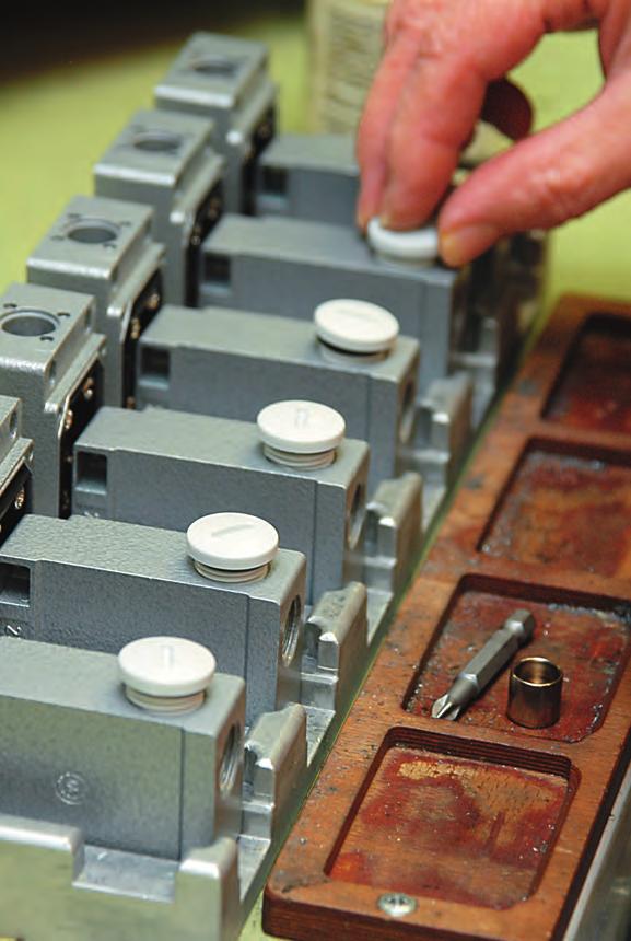
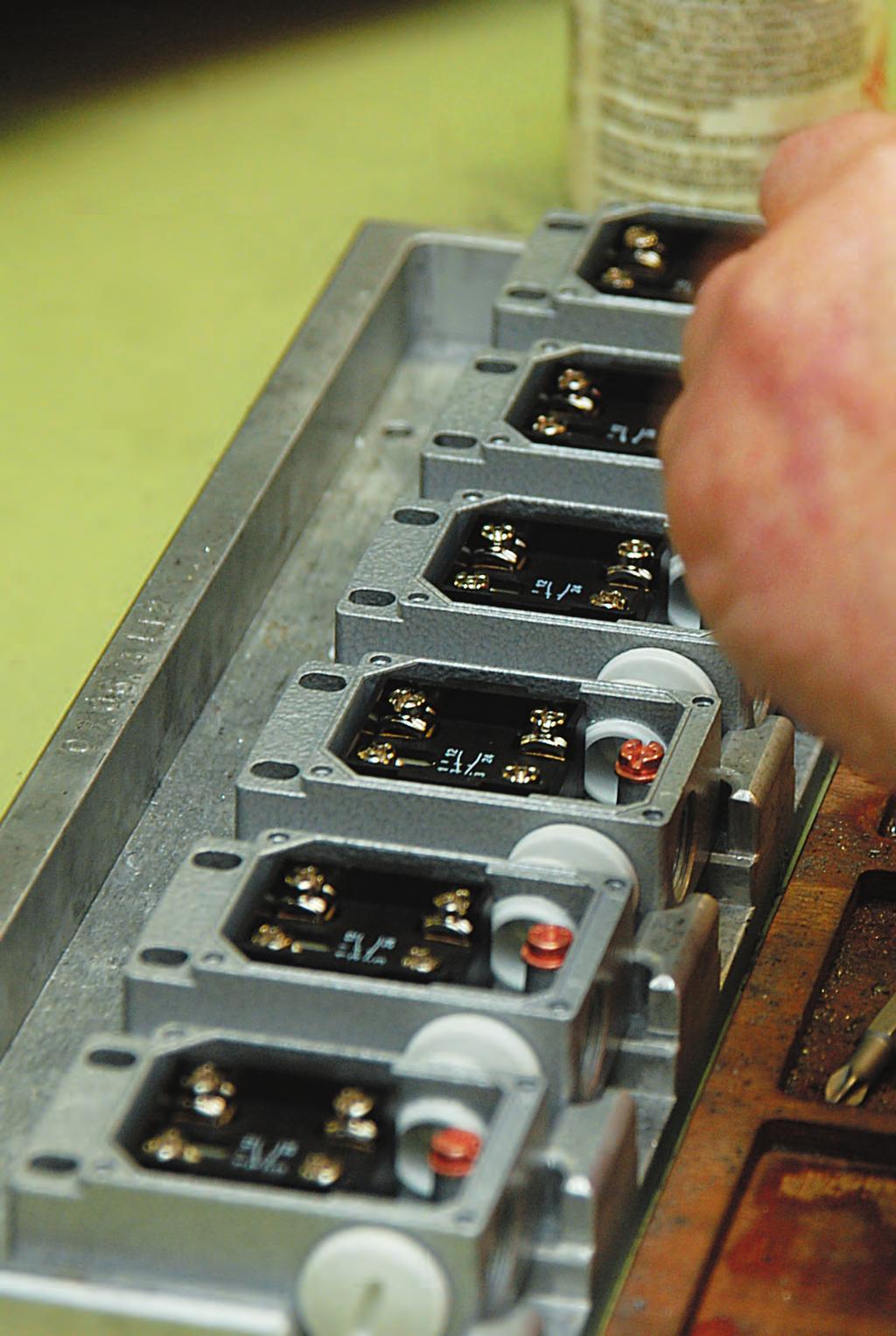
27 PRODUCTION PROCESS ASSEMBLY MOUNTING OF THE SWITCH INSERTS AT EMERGENCY PULL-WIRE SWITCHES 27
 - Wire pull and breakage detection // ZS 441 Technical data 28 Standards EN 60947-5-1, EN")
28 Emergency pull-wire switches, one-side actuation // Series ZS Metal enclosure - 2 contacts - Wire length up to 60 m N spring force for max. 60 m - Release by push button or key possible - Available without unlocking mechanism (per EN ) - Wire pull and breakage detection // ZS 441 Technical data 28 Standards EN , EN , EN ISO 13850, EN ISO Enclosure aluminium die-cast, enamel finish Cover aluminium die-cast, enamel finish Degree of protection ZS 441 VD: IP 65; ZS 441 VS: IP 54 to IEC/EN Contact material silver Switching elements change-over contact with double break or 2 NC contacts Switching system snap action, positive break NC contacts A Connection screw connection terminals Cable cross section max. 2.5 mm 2 (incl. conductor ferrules) Cable entry 3 x M20 x 1.5 B 10d (10 % load) T M max. 20 years U imp 6 kv U i 400 V I the 6 A Utilisation category AC-15 I e /U e 6 A/400 VAC Max. fuse rating 6 A gg/gn fuse Ambient temperature 25 C +70 ºC Mech. life > operations Indicator lamp as option Max. wire length 60 m Features wire pull and breakage detection Approvals d e Contact variants: switch travel/contacts Snap action 1 NC/1 NO contact ZS 441 1Ö/1S 2 NC contacts ZS 441 2Ö Ordering details ZS 441 1Ö/1S VD/150 N-G Indicator lamp, accessories (appendix) 150 N pre-stress force VD push button release (VS key release) 1 NC/1 NO contact (2Ö) Series Emergency pull-wire switch At 5 m distance intermediate wire supports are required. One wire thimble is provided. Details related to pre-stress and actuating forces are indicated on page 13.
29 Emergency pull-wire switches, one-side actuation // Series ZS 441, mounting Legend 1 Cable tensioner system TS Eye bolt M8 x 70 with nut Wire clamp Wire thimble Compensation spring ZS 73/75-200N Pull-wire per metre // Mounting without compensation spring l [m] ΔT [K] // Mounting with compensation spring 29 l [m] ΔT [K]
30 Emergency pull-wire switches, one-side actuation // Series ZS 441, variants - Indicator lamps for various voltages are indicated in chapter accessories in the appendix - Indicator lamp position in the left side cable entry, other positions possible on request // Push-button release VD Push-button release ZS 441 1Ö/1S VD/150 N ZS 441 2Ö VD/150 N // Key release VS ø38 ø22 29 Key release ZS 441 1Ö/1S VS/150 N ZS 441 2Ö VS/150 N ø M20x1, ,5

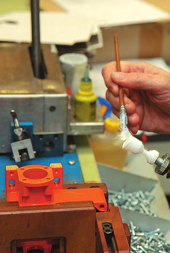
31 PRODUCTION PROCESS ASSEMBLY MOUNTING OF THE PULL-WIRE UNIT AT EMERGENCY PULL-WIRE SWITCHES 31
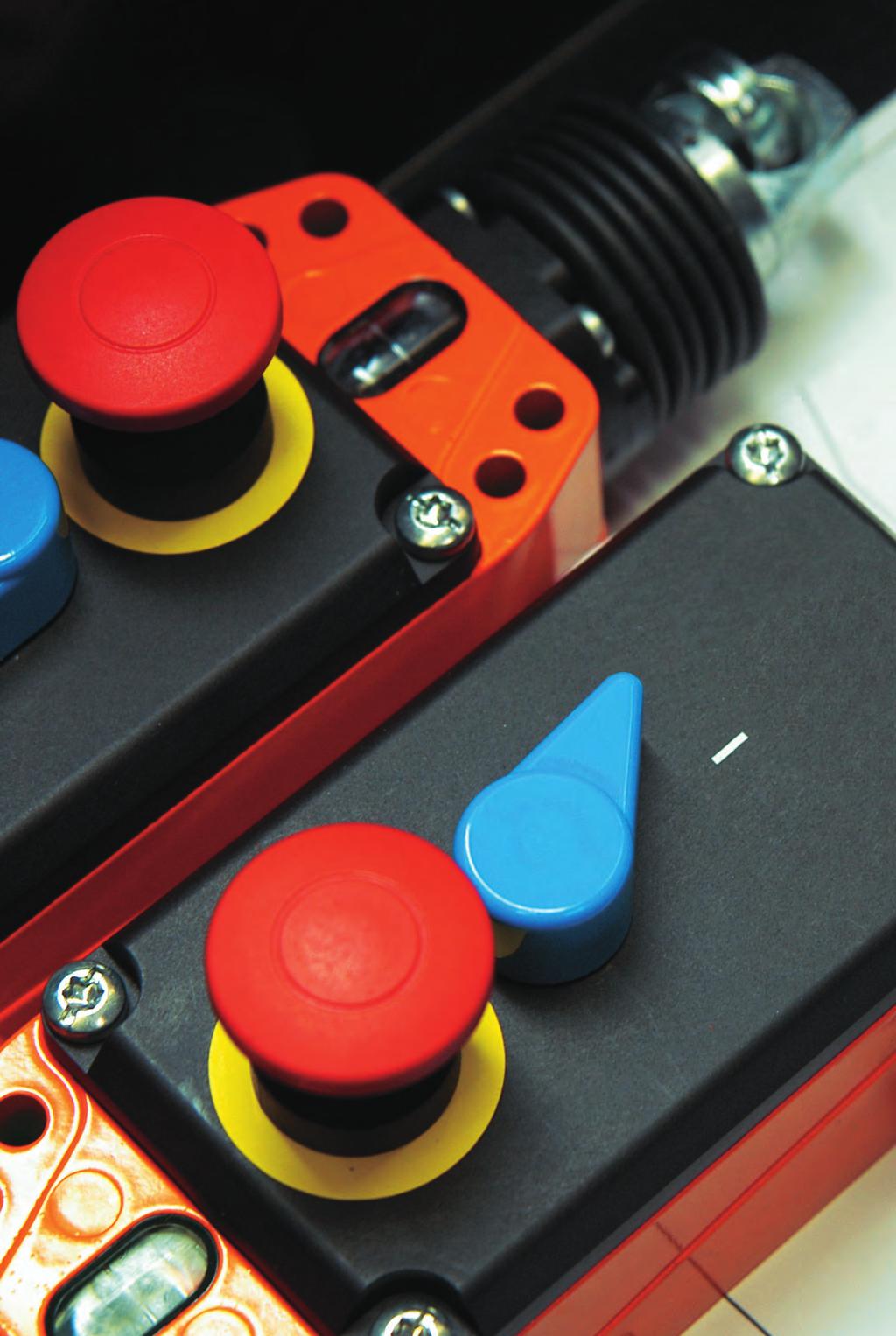
32 Emergency pull-wire switches, one-side actuation // Series ZS 80 - Metal enclosure - 4 contacts - Position indicator and integrated emergency-stop push-button - Wire length up to 100 m - Pretensioning force 100 N - Lever for release and position indication - Watertight collar - Wire pull and breakage detection - Indicator lamp available for various voltages see chapter accessories in the appendix // ZS 80 Technical data 32 Standards EN , EN , EN ISO 13850, EN ISO Enclosure aluminium die-cast, enamel finish Cover glass-fibre reinforced, shock-proof thermoplastic, ultramid Degree of protection IP 67 to IEC/EN Contact material silver Switching elements 2 NC/2 NO, 3 NC/1 NO or 4 NC contacts with double break Switching system slow action, positive break NC contacts A Connection 2 x 4-pole terminal block Cable cross section max. 2.5 mm 2 (incl. conductor ferrules) Cable entry 3 x M20 x 1.5 B 10d (10 % load) T M max. 20 years U imp 2.5 kv U i 250 V I the 2 A Utilisation category AC-15 I e /U e 2 A/250 VAC Max. fuse rating 2 A gg/gn-fuse Ambient temperature 25 C +70 ºC Mech. life > operations Indicator lamp as option Max. wire length 100 m Features wire pull and breakage detection Approvals H d a e Contact variants: switch travel/contacts Ordering details ZS 80 2Ö/2S WVD Snap action 2 NC/2 NO contact ZS 80 2Ö/2S WVD NC/1 NO contacts ZS 80 3Ö/1S WVD NC contacts ZS 80 4Ö WVD VD lever release W watertight collar 2 NC/2 NO contacts (3Ö/1S, 4Ö) Series Emergency pull-wire switch At 5 m distance intermediate wire supports are required. One wire thimble is provided. Details related to pre-stress and actuating forces are indicated on page 13.
33 Emergency pull-wire switches, one-side actuation // Series ZS 80, mounting Legend 1 Cable tensioner system TS Eye bolt M8 x 70 with nut Wire clamp Wire thimble Compensation spring ZS Pull-wire per metre // Mounting without compensation spring 6 6 l [m] ΔT [K] // Mounting with compensation spring l [m] ΔT [K] // Mounting with 2 emergency pull-wire switches l [m] ΔT [K]
34 Emergency pull-wire switches, two-side actuation // Series ZS 73 S - Metal enclosure - 2 or 3 contacts - Wire length up to 2 x 100 m - Release by push button or key possible - Available without unlocking mechanism (per EN ) - Wire pull and breakage detection - Ex version available // ZS 73 S Technical data ,5 6,5 48 M20x1,5 ø Standards EN , EN , EN ISO 13850, EN ISO Enclosure aluminium die-cast, enamel finish; ZS 73 NIRO: aluminium die-cast, hard-coated and enamelled Cover glass-fibre reinforced, shock-proof thermoplastic, ultramid Degree of protection ZS 73 S VD: IP 65; ZS 73 S VS: IP 54 to IEC/EN Contact material silver Switching elements change-over contact with double break or 2 NC or 2 NC/1 NO contacts Switching system snap action, positive break NC contacts A Connection screw connection terminals Cable cross section max. 2.5 mm 2 (incl. conductor ferrules) Cable entry 2 x M20 x 1.5 B 10d (10 % load) T M max. 20 years U imp 2 contacts: 6 kv, 3 contacts: 1 kv U i 2 contacts: 400 V, 3 contacts: 250 V I the 2 contacts: 6 A, 3 contacts: 2 A Utilisation category AC-15 I e /U e 2 contacts: 6 A/400 VAC, 3 contacts: 2 A/250 VAC Max. fuse rating 2 contacts: 6 A gg/gn-fuse, 3 contacts: 2 A gg/gn-fuse Ambient temperature 25 C +70 ºC Mech. life > operations Indicator lamp as option Max. wire length 2 x 100 m Features wire pull and breakage detection Approvals H d a e Contact variants: switch travel/contacts Ordering details ZS 73 S 1Ö/1S VD-NIRO-G Snap action 1 NC/1 NO contact ZS 73 S 1Ö/1S 2 NC contacts ZS 73 S 2Ö 2 NC/1 NO contacts ZS 73 S 2Ö/1S Indicator lamp, accessories (appendix) NIRO pull-wire unit VD push button release (VS key release, blank without manual latching)) 1 NC/1 NO contact (2Ö, 2Ö/1S) S two-side actuation Series Emergency pull-wire switch At 4 m distance intermediate wire supports are required. Two compensation springs type ZS 73/75 S must be installed see chapter accessories in the appendix.
35 Emergency pull-wire switches, two-side actuation // Series ZS 73 S, mounting Legend 1 Cable tensioner system TS Eye bolt M8 x 70 with nut Wire clamp Wire thimble Compensation spring ZS 73/75 S Pull-wire per metre Note - Always mount emergency pull-wire switch in middle position. // Mounting with compensation spring 6 6 0,5 m 0,5 m 4m 4m 35
36 Emergency pull-wire switches, two-side actuation // Series ZS 73 S, variants - Indicator lamps for various voltages are indicated in chapter accessories in the appendix - Indicator lamp position in the left side cable entry, other positions possible on request - With 2 cable entries available on request // Push-button release VD ,5 ø Push-button release ZS 73 S 1Ö/1S VD ZS 73 S 2Ö VD ZS 73 S 2Ö/1S VD ,5 M20x1, // Stainless Steel ZS 73 S NIRO - ZS 73 NIRO: pull-wire lever and screws made of stainless steel , hard-coated enclosure with enamel finish Stainless Steel/Push-button release ZS 73 S 1Ö/1S VD Niro ZS 73 S 2Ö/1S VD // Key release VS ,5 ø Key release ZS 73 S 1Ö/1S VS on request , ,5 M20x1,

37 QUALITY MANAGEMENT SHOCK TEST OF AN EMERGENCY PULL-WIRE SWITCH 37
 - Wire pull and breakage detection - Version with Dupline or Dupline Safe available on request - Ex version available // ZS 75 S Technical data 38")
38 Emergency pull-wire switches, two-side actuation // Series ZS 75 S - Metal enclosure - 2 or 4 contacts - Wire length up to 2 x 100 m - Release by push button or key or pull-ring possible - Available without unlocking mechanism (per EN ) - Wire pull and breakage detection - Version with Dupline or Dupline Safe available on request - Ex version available // ZS 75 S Technical data 38 Standards EN , EN , EN ISO 13850, EN ISO Enclosure aluminium die-cast, enamel finish Cover aluminium die-cast, enamel finish Degree of protection ZS 75 S VD: IP 65; ZS 75 S VS: IP 54; ZS 75 S VZ: IP 67 to IEC/EN Contact material silver Switching elements change-over contact with double break or 2 NO/2 NC or 4 NC contacts Switching system snap action, positive break NC contacts A Connection screw connection terminals Cable cross section max. 2.5 mm 2 (incl. conductor ferrules) Cable entry 2 x M25 x 1.5 B 10d (10 % load) T M max. 20 years U imp 6 kv U i 400 V I the 6 A Utilisation category AC-15 I e /U e 6 A/400 VAC Max. fuse rating 6 A gg/gn fuse Ambient temperature 25 C +70 ºC Mech. life > operations Indicator lamp as option Max. wire length 2 x 100 m Features wire pull and breakage detection Approvals H d a e Contact variants: switch travel/contacts Ordering details ZS 75 S 2Ö/2S VD-G-DP Snap action 1 NC/1 NO contact ZS 75 S 1Ö/1S 2 NC/2 NO contacts ZS 75 S 2Ö/2S 4 NC contacts ZS 75 S 4Ö Dupline (DPS Dupline Safe) Indicator lamp, accessories (appendix) VD push button release (VS key rel./vz pull-ring rel.) 2 NC/2 NO contacts (1Ö/1S, 4Ö) S two-side actuation Series Emergency pull-wire switch At 4 m distance intermediate wire supports are required. Two compensation springs type ZS 73/75 S must be installed see chapter accessories in the appendix.
39 Emergency pull-wire switches, two-side actuation // Series ZS 75 S, mounting Legend 1 Cable tensioner system TS Eye bolt M8 x 70 with nut Wire clamp Wire thimble Compensation spring ZS 73/75 S Pull-wire per metre Note - Always mount emergency pull-wire switch in middle position. // Mounting with compensation spring 6 6 0,5 m 0,5 m 4m 4m 39
40 Emergency pull-wire switches, two-side actuation // Series ZS 75 S, variants - Indicator lamps for various voltages are indicated in chapter accessories in the appendix - Indicator lamp position in the left side cable entry, other positions possible on request // ZS 75 S Push-button release ZS 75 S 1Ö/1S VD ZS 75 S 2Ö/2S VD ZS 75 S 4Ö VD // Key release VS ø Key release ZS 75 S 1Ö/1S VS ZS 75 S 2Ö/2S VS , M25x1, // Pull-ring release VZ ø , Pullring release ZS 75 S 2Ö/2S VZ IP67 Extreme M25x1,

41 QUALITY MANAGEMENT LIFE TEST OF UNLOCKING MECHANISM 41
 - Wire pull and breakage detection - Version with Bus or Si-Bus available on request // ZS 91 S Technical data 42 Standards EN 60947-5-1, EN 60947-5-5, EN ISO 13850, EN")
42 Emergency pull-wire switches, two-side actuation // Series ZS 91 S - Thermoplastic enclosure - 4 or 6 contacts - Wire length up to 2 x 100 m - Release by lever possible - Available without unlocking mechanism (per EN ) - Wire pull and breakage detection - Version with Bus or Si-Bus available on request // ZS 91 S Technical data 42 Standards EN , EN , EN ISO 13850, EN ISO Enclosure glass-fibre reinforced, shock-proof thermoplastic, ultramid, UV resistant to EN ISO 4892 Cover glass-fibre reinforced, shock-proof thermoplastic, ultramid, UV resistant to EN ISO 4892 Degree of protection IP 66/67 to IEC/EN Contact material silver Switching elements 2 NC/2 NO, 3 NC/1 NO, 4 NC, 3 NC/3 NO or 4 NC/2 NO contacts with double break Switching system snap action, positive break NC contacts A Connection screw connection terminals Cable cross section max. 2.5 mm 2 (incl. conductor ferrules) Cable entry 2 x M25 x 1.5 B 10d (10 % load) ZS 91 S VD: > operations ZS 91 S: > 2 million operations T M max. 20 years U imp 6 kv U i 400 V I the 6 A Utilisation category AC-15 I e /U e 6 A/400 VAC Max. fuse rating 6 A gg/gn fuse Ambient temperature 40 C +85 ºC Mech. life ZS 91 S VD: > operations ZS 91 S: > 1 million operations Max. wire length 2 x 100 m Features wire pull and breakage detection Contact variants: switch travel/contacts Ordering example ZS 91 S 2Ö/2S VD-BUS Snap action 2 NC/2 NO contacts ZS 91 S 2Ö/2S A B NC/3 NO contacts ZS 91 S 3Ö/3S VD A B C 4 NC/2 NO contacts ZS 91 S 4Ö/2S VD A B C Bus (Si-Bus) VD lever release (blank without manual latching) 2 NC/2 NO contacts S two-side actuation Series Emergency pull-wire switch At 3 m distance intermediate wire supports are required. Two compensation springs type RZ 130K must be installed see chapter accessories in the appendix.
43 Emergency pull-wire switches, two-side actuation // Series ZS 91 S, mounting Legend 1 Cable tensioner system TS Eye bolt M8 x 70 with nut Wire clamp Wire thimble Compensation spring ZS 90/91 S Pull-wire per metre Note - Always mount emergency pull-wire switch in middle position. // Mounting with compensation spring 0,5 m 0,5 m 3m 3m 43
44

45 Belt-alignment switches // Series ES 61 SR from page 48 // Series ES 98 SR from page 49 // Series ZS 73 SR from page 50 // Series ZS 75 SR from page 52 // Series ZS 91 SR from page ZS 73 SR
46 46
47 Belt-alignment switches Application Belt-alignment switches are suitable for applications with handling equipment. Here they are installed e.g. at both sides of a conveyor belt in order to monitor the misalignment of the belt. Belt misalignment, evoked by for example not in the middle of conveyor belt positioned goods or pollution of track idlers and deflection pulleys, can lead without any monitoring measurements to damage, destruction, material covering and dropping. Application Monitoring an conveyor belt Design and mode of operation Belt-alignment switches are actuated when the conveyor belt becomes misaligned. Depending on the plant arrangements, this signal can either be used to switch the equipment off or to provide automatic correction of the belt alignment. Thus they should be installed at both sides of the conveyor belt close to the deflection and drive pulleys. In case of very long conveyor systems further belt-alignment switches must be installed. Those are actuated with the misalignment of the conveyor belt. This signal can either switch the system off or start an automatic belt position correction, as well as at the same time generate an optical or acoustic indicating or warning signal. All belt-alignment switches have positive break NC contacts and those of series ZS also have a mechanical latching. At actuation the NC contacts are opened and latched mechanically. The release can either be carried by push button or key. Thus an unintentional, automatic restart of the conveyor belt is prevented. All belt-alignment switches bear the CE mark according to the Machinery Directive 2006/42/EC. Belt-alignment switch in actuated state 47
48 Belt-alignment switches // Series ES 61 SR - Metal enclosure - Slow action: 2 contacts // ES 61 SR Technical data 48 Standards EN , EN ISO Enclosure aluminium die-cast, enamel finish Cover steel, enamel finish Degree of protection IP 65 to IEC/EN Contact material silver Switching elements change-over contact with double break with galvanically separated contact bridges Switching system slow action Connection screw connection terminals Cable cross section max. 2.5 mm 2 (incl. conductor ferrules) Cable entry 3 x M20 x 1.5 B 10d (10 % load) 2 million T M max.20 years U imp 6 kv U i 400 V I the 10 A Utilisation category AC-15 I e /U e 16 A/400 VAC Max. fuse rating 16 A gg/gn fuse Ambient temperature 20 C +80 ºC Mech. life > 1 million operations Switching frequency 3600/h Approvals e Contact variants: switch travel/contacts Slow action 1 NC/1 NO contact ES 61 SR 1Ö/1S Ordering details ES 61 SR 1Ö/1S 1 NC/1 NO contact, (UE 1 NC/1 NO contact with contact overlapping) SR Belt-alignment lever Series S Slow action (M snap action) 1 NC/1 NO contact ES 61 SR UE with overlapping
49 Belt-alignment switches // Series ES 98 SR - Metal enclosure - Slow action: 2 contacts - Wiring compartment - Adjustable-length rod lever with nylon roller - For light- and medium-heavy applications - Ex version available // ES 98 SR Technical data Standards EN ; EN ISO Enclosure zinc die-cast, enamel finish Degree of protection IP 67 to IEC/EN Contact material silver Switching elements 1 NC/1 NO, 2 NC or 1 NC/1 NO contacts with overlapping with double break, galvanically separated contact bridges Switching system slow action, positive break NC contacts A Connection screw connection terminals Cable section max. 2.5 mm 2 (incl. conductor ferrules) Cable entry 1 x M20 x 1.5 B 10d (10 % load) 2 million T M max. 20 years U imp 4 kv U i 250 V I the 6 A Utilisation category AC-15; DC-13 I e /U e 6 A/250 VAC; 0.25 A/230 VDC Max. fuse rating 6 A gg/gn fuse Ambient temperature 20 C +60 ºC Mechanical life > 1 million operations Frequency of operation 1800/h 49 Contact variants: switch travel/contacts Slow action 1 NC/1 NO contacts ES 98 SR Ordering example ES 98 SR-11 1 NC/1 NO contacts (2Ö) SR belt-alignment lever Series S Slow action (M snap action) 2 NC ES 98 SR

50 Belt-alignment switches // Series ZS 73 SR - Metal enclosure - 2 contacts - Release by push button or key possible - Belt-alignment roller made of stainless steel Ex version available // ZS 73 SR Technical data M20x1,5 27 6,5 ø ø Standards EN , EN ISO Enclosure aluminium die-cast, enamel finish; Cover glass-fibre reinforced, shockproof thermoplastic, ultramid Degree of protection ZS 73 SR VD: IP 65; ZS 73 SR VS: IP 54 to IEC/EN Contact material silver Switching elements change-over contact with double break or 2 NC contacts Switching system snap action, positive break NC contacts A Connection screw connection terminals Cable cross section max. 2.5 mm 2 (incl. conductor ferrules) Cable entry 2 x M20 x 1.5 B 10d (10 % load) ZS 73 SR: 2 million; ZS 73 SR VD/VS: T M max. 20 years U imp 6 kv U i 400 V I the 6 A Utilisation category AC-15 I e /U e 6 A/400 VAC Max. fuse rating 6 A gg/gn fuse Ambient temperature 25 C +70 ºC Mech. life ZS 73 SR: > 1 million operations ZS 73 SR VD/VS: > operations Indicator lamp as option Approvals H d a e M20x1, M20x1, Contact variants: switch travel/contacts Snap action 1 NC/1 NO contact ZS 73 SR 1Ö/1S 2 NC contacts ZS 73 SR 2Ö Ordering details ZS 73 SR 1Ö/1S VD-G Indicator lamp, see accessories (appendix) VD Push button release (VS key release, blank without manual latching) 1 NC/1 NO contact (2Ö) SR Belt-alignment lever Series Belt-alignment switch
51 Belt-alignment switches // Series ZS 73 SR, variants - Indicator lamps for various voltages are indicated in chapter accessories in the appendix - Indicator lamp position in the left side cable entry, other positions possible on request - With 2 cable entries available on request // Push-button release VD M20x1,5 27 6,5 ø Push-button release ZS 73 SR 1Ö/1S VD Without release ZS 73 SR 1Ö/1S ø M20x1,5 // Key release VS M20x1, M20x1,5 27 6,5 ø ø M20x1,5 M20x1, Key release ZS 73 SR 1Ö/1S VS ,
52 Belt-alignment switches // Series ZS 75 SR - Metal enclosure - 2 or 4 contacts - Release by push button or key possible - Belt-alignment roller made of stainless steel Version with Dupline or Dupline Safe available on request - Ex version available // ZS 75 SR Technical data ø Standards EN , EN ISO Enclosure aluminium die-cast, enamel finish Cover aluminium die-cast, enamel finish Degree of protection ZS 75 SR VD: IP 65; ZS 75 SR VS: IP 54 to IEC/EN Contact material silver Switching elements change-over contact with double break or 2 NO and 2 NC or 4 NC Switching system snap action, positive break NC contacts A Connection screw connection terminals Cable cross section max. 2.5 mm 2 (incl. conductor ferrules) Cable entry 2 x M25 x 1.5 B 10d (10 % load) ZS 75 SR: 2 million; ZS 75 SR VD/VS: T M max. 20 years U imp 6 kv U i 400 V I the 6 A Utilisation category AC-15 I e /U e 6 A/400 VAC Max. fuse rating 6 A gg/gn fuse Ambient temperature 25 C +70 ºC Mech. life ZS 75 SR: > 1 million operations ZS 75 SR VD/VS: > operations Indicator lamp as option Approvals H d a e ø32 ø6, M25x1,5 70 Contact variants: switch travel/contacts Snap action 1 NC/1 NO contact ZS 75 SR 1Ö/1S 2 NC/2 NO contacts ZS 75 SR 2Ö/2S A B 4 NC contacts ZS 75 SR 4Ö Ordering details ZS 75 SR 2Ö/2S VD-G-DP DP Dupline (DPS Dupline Safe) Indicator lamp, see accessories (appendix) VD Push button release (VS key release, blank without manual latching) 2 NC/2 NO contacts (1Ö/1S, 4Ö) SR Belt-alignment lever Series Belt-alignment switch
53 Belt-alignment switches // Series ZS 75 SR, variants - Indicator lamps for various voltages are indicated in chapter accessories in the appendix - Indicator lamp position in the left side cable entry, other positions possible on request // Push-button release VD Without release ZS 75 SR 1Ö/1S ZS 75 SR 2Ö/2S ø ø33 Push-button release ZS 75 SR 1Ö/1S VD ZS 75 SR 2Ö/2S VD ø6, M25x1,5 70 // Key release VS ,5 Key release ZS 75 SR 1Ö/1S VS ZS 75 SR 2Ö/2S VS ø ø32 ø6, M25x1,

54 Belt-alignment switches // Series ZS 91 SR - Thermoplastic enclosure - 4 or 6 contacts with contact staggering: 1 NC and 1 NO contact switching at 15, 1 NC and 1 NO contact switching at 25 - Release by lever VD possible - Belt-alignment lever continuously adjustable - Version with Bus or Si-Bus available on request // ZS 91 SR Technical data ø Standards EN ; EN ISO Enclosure glass-fibre reinforced, shock-proof thermoplastic, ultramid, UV resistant to EN ISO 4892 Cover glass-fibre reinforced, shock-proof thermoplastic, ultramid, UV resistant to EN ISO 4892 Degree of protection IP 66/67 to IEC/EN Contact material silver Switching elements 1 NC/1 NO, 2 NC/2 NO, 3 NC/1 NO, 3 NC/3 NO, 4 NC or 4 NC/2 NO contacts with double break Switching system snap action, positive break NC contacts A Connection Screw connection terminals Cable cross section max. 2.5 mm 2 (incl. conductor ferrules) Cable entry 2 x M25 x 1.5 B 10d (10 % load) ZS 91 SR VD: , ZS 91 SR: 2 million T M max. 20 years U imp 6 kv U i 400 V I the 6 A Gebrauchskategorie AC-15 I e /U e 6 A/400 VAC Max. fuse rating 6 A gg/gn-fuse Ambient temperature 40 C +85 ºC Mech. life ZS 91 SR VD: > operations, ZS 91 SR: > > 1 million operations M25x1, ,5 34, ,5 Contact variants: switch travel/contacts Snap action 2 NC/2 NO contacts ZS 91 SR 2Ö/2S VD A B 2 NC/2 NO contacts ZS 91 SR 1ÖS/1ÖS with contact staggering A B Ordering example ZS 91 SR 1ÖS/1ÖS VD-BUS Bus (Si-Bus) VD lever release (blank without manual latching) 2 NC/2 NO contacts SR belt-alignment lever Series Belt-alignment switch

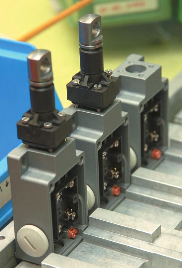
55 PRODUCTION PROCESS ASSEMBLY MOUNTING OF ACTUATOR 55
56 56

57 Pull-wire switches // Series ES/EM 95 Z from page 62 // Series ES 51 Z from page 64 // Series ES/EM 41 Z from page 66 // Series ES/EM 61 Z from page 70 // Series ZS 70 from page 72 // Series ZS 71 from page ES 61 WZ
58 58
59 Pull-wire switches Application Pull-wire switches are suitable as transducers for starting machines or to open and close electrically-powered doors, gates and barriers. Design and mode of operation Pull-wire switches are actuated manually by pulling. There are variants with and without latching. The pull-wire switches without latching generate a switching impulse on actuation. With the devices with latching the switching impulse is maintained until repeated actuation. An important feature for the selection of pull-wire switches are the mounting possibilities, wall or ceiling mounting. For your support you find a selection table on the following page. In the appendix the mounting accessories for pull-wire switches can be selected. All pull-wire switches presented in this chapter bear the CE mark according to the Low Voltage Directive 06/95/EC. Application Wall mounting as door opener Ceiling mounting 59
60 Selection table Pull-wire switches // Series // Mounting possibilities ES/EM 95 Z, on page 62 - Thermoplastic enclosure x x - Ceiling or wall mounting ES 51 Z, on page 64 - Metal enclosure x - Wall mounting ES/EM 41 Z, on page 66 - Metal enclosure x x - Ceiling or wall mounting 60 ES/EM 61 Z, on page 70 - Metal enclosure x x - Ceiling or wall mounting ZS 70, on page 72 - Thermoplastic enclosure x - Wall mounting ZS 71, on page 73 - Metal enclosure x - Wall mounting
61 61

62 Pull-wire switches // Series ES 95 Z - Thermoplastic enclosure - Wall or ceiling mounting - Slow action: 2 contacts - Horizontal slotted mounting holes - Double insulated X // ES 95 Z Technical data 62 Standards EN Enclosure glass-fibre reinforced, shockproof thermoplastic, self-extinguishing UL 94-V0 Degree of protection IP 67 to IEC/EN Contact material silver Switching elements change-over contact with double break, galvanically separated contact bridges Switching system slow action, positive break NC contacts A Connection screw connection terminals Cable cross section max. 2.5 mm 2 (incl. conductor ferrules) Cable entry 1 x M20 x 1.5 U imp 4 kv U i 400 V I the 6 A Utilisation category AC-15; DC-13 Ie/Ue 6 A/400 VAC; 0.25 A/230 VDC Max. fuse rating 6 A gg/gn fuse Mech. life > 1 million operations Switching frequency 1800/h Ambient temperature 20 C + 80 ºC Contact opening 2 x 3.5 mm Actuating force 20 N Features pull-wire function Approvals e a Contact variants: switch travel/contacts Slow action 1 NC/1 NO contact ES 95 Z 1Ö/1S Ordering details ES 95 Z 1Ö/1S 1 NC/1 NO contact Z Actuator towing eye Series S Slow action
63 Pull-wire switches // Series ES 95 Z, variants //ES 95 Z Slow action ES 95 Z 1Ö/1S ES 95 Z 2S // ES 95 WH/90 1Ö/1S 63 - Suitable for wall- and ceiling mounting - Version for door/gate opening ES 95 WH/90 1Ö/1S: including 3.2 m long nylon pull-wire and rubber ball, slow action 1 NC/1 NO contact Slow action ES 95 WH/90 1Ö/1S-3,2m

64 Pull-wire switches // Series ES 51 Z - Metal enclosure - Wall mounting - Slow action: 2 contacts - Small design - Pull-wire function // ES 51 Z Technical data 64 Standards EN Enclosure aluminium die-cast, enamel finish Cover steel, enamel finish Degree of protection IP 65 to IEC/EN Contact material silver Switching elements change-over contact with double break with galvanically separated contact bridges Switching system slow action Connection screw connection terminals Cable cross section max. 2.5 mm 2 (incl. conductor ferrules) Cable entry 1 x M16 x 1.5 U imp 4 kv U i 400 V I the 4 A Utilisation category AC-15 I e /U e 4 A/400 VAC Max. fuse rating 4 A gg/gn-fuse Ambient temperature 20 C +80 ºC Mech. life > 1 million operations Switching frequency 3600/h Actuating force max. 40 N Features pull-wire function Approvals e a Contact variants: switch travel/contacts Slow action 1 NC/1 NO contact ES 51 Z 1Ö/1S Ordering details ES 51 W Z 1Ö/1S 1 NC/1 NO contact Z Actuator towing eye W Collar Series S Slow action
65 Pull-wire switches // Series ES 51 Z, variants //ES 51 Z Slow action ES 51 Z 1Ö/1S // Collar W M16x1, Watertight collar W for protection against penetration of dirt Collar/Slow action ES 51 WZ 1Ö/1S , ø10

66 Pull-wire switches // Series ES/EM 41 Z - Metal enclosure - Wall or ceiling mounting - Slow or snap action: 2 contacts - Pull-wire function // ES/EM 41 Z Technical data 66 Standards EN Enclosure aluminium die-cast, enamel finish Cover steel, enamel finish Degree of protection IP 65 to IEC/EN Contact material silver Switching elements change-over or 2 NO contacts with double break Switching system slow or snap action Connection M3.5 screw connection terminals Cable cross section max. 2.5 mm 2 (incl. conductor ferrules) Cable entry 3 x M16 x 1.5 U imp 4 kv U i 400 V I the 10 A Utilisation category AC-15 I e /U e 6 A/400 VAC Max. fuse rating 6 A gg/gn fuse Ambient temperature 20 C +80 ºC Mech. life > 1 million operations Switching frequency 3600/h Actuating force max. 45 N Features pull-wire function Approvals e a Contact variants: switch travel/contacts Snap action Slow action 1 NC/1 NO contact EM 41 Z 1Ö/1S ES 41 Z 1Ö/1S 2 NO contacts ES 41 Z 2S Ordering details ES 41 W Z 1Ö/1S DM DM Ceiling mounting, including ceiling mounting plate 1 NC/1 NO contact, (2S 2 NO contacts) Z Actuator towing eye W Collar Series S Slow action (M snap action)
67 Pull-wire switches // Series ES/EM 41 Z, variants // ES/EM 41 Z Slow action ES 41 Z 1Ö/1S ES 41 Z 2S Snap action EM 41 Z 1Ö/1S // Collar W Watertight collar for protection against penetration of dirt M16x1,5 13, Collar/Slow action ES 41 WZ 1Ö/1S ES 41 WZ 2S Collar/Snap action EM 41 WZ 1Ö/1S ,2 24 ø10 20 // Ceiling mounting DM - Version for ceiling mounting with mounting plate Ceiling mounting/slow action ES 41 Z 1Ö/1S ceiling mounting DM
68 Pull-wire switches // Series ES/EM 41 Z, variants // ES 41 WH/90 1Ö/1S - Version for ceiling and wall mounting ES 41 WH/90 1Ö/1S - Version for door/gate opening ES 41 WH/90 1Ö/1S: including 3.2 m long nylon pull-wire with rubber ball, including mounting screws and rawlplugs, metal enclosure with thermoplastic cover, slow action 1 NC/1 NO contact Slow action ES 41 WH/90 1Ö/1S-3,

69 PRODUCTION PROCESS ASSEMBLY MOUNTING OF PULL-WIRE SWITCHES 69

70 Pull-wire switches // Series ES/EM 61 Z - Metal enclosure - Wall or ceiling mounting - Slow or snap action: 2 contacts - Pull-wire function - Ex version available // ES/EM 61 Z Technical data 70 Standards EN Enclosure aluminium die-cast, enamel finish Cover steel, enamel finish Degree of protection IP 65 to IEC/EN Contact material silver Switching elements change-over or 2 NO contacts with double break and galvanically separated contact bridges Switching system slow or snap action Connection screw connection terminals Cable cross section max. 2.5 mm 2 (incl. conductor ferrules) Cable entry 3 x M20 x 1.5 U imp 6 kv U i 400 V I the 10 A Utilisation category AC-15 I e /U e ES 61: 16 A/400 VAC, EM 61: 6 A/400 VAC Max. fuse rating ES 61: 16 A gg/gn fuse EM 61: 6 A gg/gn fuse Ambient temperature 20 C +80 ºC Mech. life > 1 million operations Indicator lamp as option Switching frequency 3600/h Actuating force max. 50 N Features pull-wire function Approvals a e Contact variants: switch travel/contacts Snap action Slow action 1 NC/1 NO contact EM 61 Z 1Ö/1S ES 61 Z 1Ö/1S 2 NO contacts ES 61 Z 2S Ordering details ES 61 W Z 1Ö/1S DM-G Indicator lamp (app) DM Ceiling mounting with mounting plate 1 NC/1 NO contact, (2S 2 NO contacts) Z Actuator towing eye W Collar Series S Slow action (M snap action)
71 Pull-wire switches // Series ES/EM 61 Z, variants - Version for wall mounting with mounting angle - Indicator lamps for various voltages are indicated in chapter accessories in the appendix // ES/EM 61 Z Slow action ES 61 Z 1Ö/1S ES 61 Z 2S Snap action EM 61 Z 1Ö/1S // Collar W Watertight collar for protection against penetration of dirt , M20x1,5 Collar/Slow action ES 61 WZ 1Ö/1S ES 61 WZ 2S Collar/Snap action EM 61 WZ 1Ö/1S , ø10 10 // Ceiling mounting DM - Version for ceiling mounting with mounting plate Ceiling mounting/slow action ES 61 Z 1Ö/1S ceiling mounting DM

72 Pull-wire switches // Series ZS 70 Z - Thermoplastic enclosure - Wall mounting - Snap action: 2 contacts - Pull-wire function // ZS 70 Z Technical data 72 Standards EN Design mounting details to EN Enclosure glass-fibre reinforced, shockproof thermoplastic, ultramid Cover glass-fibre reinforced, shockproof thermoplastic, ultramid Degree of protection IP 67 to IEC/EN Contact material silver Switching elements change-over contact with double break with galvanically separated contact bridges Switching system snap action, positive break NC contacts A Connection screw connection terminals Cable cross section max. 2.5 mm 2 (incl. conductor ferrules) Cable entry 1 x M20 x 1.5 U imp 6 kv U i 400 V I the 6 A Utilisation category AC-15 I e /U e 6 A/400 VAC Max. fuse rating 6 A gg/gn fuse Ambient temperature 10 C +70 ºC Mech. life > 1 million operations Switching frequency 1800/h Actuating force max. 85 N Features pull-wire function Approvals H d a e Contact variants: switch travel/contacts Snap action Order No. 1 NC/1 NO contact ZS 70 Z 1Ö/1S Ordering details ZS 70 Z 1Ö/1S 1 NC/1 NO contact Z Actuator towing eye Series Pull-wire switch
73 Pull-wire switches // Series ZS 71 Z - Metal enclosure - Wall mounting - Slow or snap action: 2 contacts - Pull-wire function with or without latching snap action: without latching slow action: with latching - Watertight collar W for protection against penetration of dirt available on request - Indicator lamps for various voltages are indicated in chapter accessories in the appendix // ZS 71 Z Technical data , ø10 M ,5 M20x1,5 Standards EN Enclosure aluminium die-cast, enamel finish Cover thermoplastic, ultramid Protection class IP 65 to IEC/EN Contact material silver Switching elements change-over contact with double break with galvanically separated contact bridges Switching system slow or snap action, positive break NC contacts A Connection screw connection terminals Cable cross section max. 2.5 mm 2 (incl. conductor ferrules) Cable entry 2 x M20 x 1.5 U imp ZS 71 Z: 6 kv, ZS 71 Z RE: 4 kv U i 400 V I the ZS 71 Z: 6 A ZS 71 Z RE: 4 A Utilisation category AC-15 I e /U e ZS 71 Z: 6 A/400 VAC, ZS 71 Z RE: 4 A/400 VAC Max. fuse rating ZS 71 Z: 6 A gg/gn fuse ZS 71 Z RE: 4 A gg/gn-fuse Ambient temperature 25 C +70 ºC Mech. life > 1 million operations Indicator lamp as option Switching frequency 1800/h Actuating force max. 80 N Features pull-wire function with or without latching Approvals H d a e Contact variants: switch travel/contacts Snap action Slow action 1 NC/1 NO contact ZS 71 Z 1Ö/1S ZS 71 Z 1Ö/1S RE Ordering details ZS 71 W Z 1Ö/1S RE-G Indicator lamp, position left side cable entry, see accessories (appendix) RE latching 1 NC/1 NO contact Z Actuator towing eye W Collar Series Pull-wire switch
74 74
75 Slack-wire switches // Series ES 41 DB from page ES 41 DB
76 76
77 Slack-wire switches Application Slack-wire switches are suitable for applications with handling equipment. There they are for example mounted at a wire in order to monitor the wire tension. Design and mode of operation Slack-wire switches monitor the pull-wire tension. With correct tension present, the switch is actuated. In case of wire breakage or stretching of the wire the switch is released and thus switches the system off. In addition, this signal can depending on the construction of the system generate an optical or acoustic indicating or warning signal. All slack-wire switches presented in this chapter bear the CE mark according to the Low Voltage Directive 06/95/EC. Application Monitoring of wire tension Slack-wire switches in released state after wire breakage 77

78 Slack-wire switches // Series ES 41 DB - Metal enclosure - Slow or snap action: 2 contacts - Available on request with various actuating rollers // ES 41 DB Technical data 78 Standards EN Enclosure aluminium die-cast, enamel finish Cover steel, enamel finish Degree of protection IP 65 to IEC/EN Contact material silver Switching elements change-over contact with double break or 2 NC contacts and galvanically separated contact bridges Switching system slow or snap action Connection screw connection terminals Cable cross section max. 2.5 mm 2 (incl. conductor ferrules) Cable entry 3 x M16 x 1.5 U imp 4 kv U i 400 V I the 6 A Utilisation category AC-15 I e /U e 6 A/400 VAC Max. fuse rating 6 A gg/gn fuse Ambient temperature 20 C +80 ºC Mech. life > 1 million operations Switching frequency max. 1800/h Approvals e Contact variants: switch travel/contacts Snap action Slow action 1 NC/1 NO contact EM 41 DB 1Ö/1S ES 41 DB 1Ö/1S 2 NC contacts ES 41 DB 2Ö Ordering details EM 41 DB/ 1Ö/1S 1 NC/1 NO contact (2Ö 2 NC contacts, UE contact overlapping), other configurations possible DB Slack-wire lever Series M Snap action (S slow action) 1 NC/1 NO contact ES 41 DB UE with overlapping
Automation // SYSTEMATIC CONTROL SWITCHGEAR. Emergency pull-wire, Pull-wire, Belt-alignment, Slack-wire switches
 Automation // SYSTEMATIC CONTROL SWITCHGEAR Emergency pull-wire, Pull-wire, Belt-alignment, Slack-wire switches 4 The Company PRODUCTS 8 Emergency pull-wire switches 12 Selection table Emergency pull-wire
Automation // SYSTEMATIC CONTROL SWITCHGEAR. Emergency pull-wire, Pull-wire, Belt-alignment, Slack-wire switches
 Automation // SYSTEMATIC CONTROL SWITCHGEAR Emergency pull-wire, Pull-wire, Belt-alignment, Slack-wire switches 6 Emergency pull-wire switches // Selection table Emergency pull-wire switches from page
Command devices Pull-wire emergency stop switches One-side operation ZS 71 range Schmersal Industrial Switchgear.
 .1.1.1 One-side operation ZS 71 range 40 30 ø10 10 22 6 8 53,5 18 24 105 33 56 Pg 13,5 52 17,5 42 15 Features To EN 418 Metal enclosure 2 contacts Small body 2 cable entries Various spring force variants
Operating instructions Pull-wire emergency-stop switches EX-ZQ About this document. Content
 Pull-wire emergency-stop switches 1. bout this document Operating instructions.............pages 1 to 6 Original 1.1 Function This operating instructions manual provides all the information you need for
Safety switches / Position switches / Command devices
 Safety switches / Position switches / Command devices SAFE SWITCHGEAR FOR DEMANDING AND CRITICAL APPLICATIONS // Control technology / Catalogue 4 The Company PRODUCTS 8 Safety switches with separate actuator
NHP SAFETY REFERENCE GUIDE
 NHP SAFETY REFERENCE GUIDE 3. PRODUCTS Safety Switches Safety Interlock Switches ST14 Series Light duty safety interlock switch, ideal for guard door monitoring applications. Thermoplastic enclosure Double
Floor and fine adjustment switches
 Floor and fine adjustment switches 6 Introduction 6-2 AS 1 6-3 ASH 2 6-4 AFH 2 6-5 Reference table technical data 6-6 Universal switches 6-7 Floor and fine adjustment switches / Introduction ➀ ➁ ➂ Floor
Operating instructions Solenoid interlock EX-AZM About this document. Content
 EX-AZM 161 1. About this document Operating instructions.............pages 1 to 6 Translation of the original operating instructions 1.1 Function This operating instructions manual provides all the information
Solenoid interlocks AZM 190 range. 128 Schmersal ,3 4,5 M20 17,5 23,5
 2.19 AZM 19 range 13 44 32 2,3 3 1 Features Voltage variants Approvals Thermoplastic enclosure Manual / Emergency release Long life Actuation on de-energisation or energisation Slim design, particularly
Technical data. Standards: IEC/EN BG-GS-ET-15
 1 Technical data Contact variants 7 30 2 2 Long life Multiple coding Thermoplastic enclosure Double insulated X 3 cable entries M20 Large wiring compartment High level of contact reliability with low voltages
Operating instructions Solenoid interlock TKM/TKF. 1. About this document. Content
 1. About this document Operating instructions.............pages 1 to 6 Original 1.1 Function This operating instructions manual provides all the information you need for the mounting, set-up and commissioning
Operating instructions Solenoid interlock AZM 161../.. 1. About this document. Content
 Solenoid interlock AZM 11../.. 1. About this document Operating instructions.............pages 1 to ranslation of the original operating instructions 1.1 Function his operating instructions manual provides
AZM 161SK 12/12RKED/TU 024
 10.06.2016 10:17:13h Datasheet AZM 161SK 12/12RKED/TU 024 Solenoid interlock / AZM 161 Thermoplastic enclosure Double insulated Interlock with protection against incorrect locking. 130 mm x 90 mm x 30
Standard Rope Pull Switches. With and Without Latching Function SIEM2 SID SIN SGC SI88. The field of application for these rope pull switches includes
 Standard Rope Pull Switches With and Without ing Function SEK SEM2 SIEM2 SD SID SID SIN SGC SI88 Because of their specifications governed by corresponding standards (see Cable Safety Pull Switches SRM/SR),
Ordering details. Approval. Classification. Global Properties :18:33h. Solenoid interlock / AZM 161
 10.06.2016 10:18:33h Datasheet AZM 161SK 12/12RKED/TU 110/230 Solenoid interlock / AZM 161 Thermoplastic enclosure Double insulated Interlock with protection against incorrect locking. 130 mm x 90 mm x
Safety door-handle system STS
 Safety door-handle system STS Full body access ha Safety door-handle system STS EN 1037 Features The safety door-handle system is suitable for all types of safety guards. Safety switches and solenoid interlocks
Solenoid interlocks AZM 161 range Schmersal. a 5,5. Pg11/M16x1,5
 .1 AZM 11 range Features Thermoplastic enclosure Manual and emergency release Long life Double insulated X High holding force, N N latching force Wiring compartment Actuation on de-energisation or energisation
Recommended use With its standard enclosure, the ENM2 limit switch can be used universally in all industrial and safety applications.
 Metal-Enclosed Limit Switches ENM2 Recommended use With its standard enclosure, the ENM2 limit switch can be used universally in all industrial and safety applications. Product advantages Standard switch
Safety rope switches with reset for emergency stop
 Safety rope switches with reset for emergency stop Selection diagram 8 8 83 ACTUATORS ACTUATORS CONTACT BLOCKS 18 9 21 1NO+ FP FD FL FC 22 33 34 LED signalling light CONDUIT ENTRIES For other available
Technical data. Standards: IEC/EN ; EN ISO ; EN 1088; BG-GS-ET-19
 1 echnical data echnical data, 1 0 3 1 104 7 90 Interlock with protection against incorrect locking hermoplastic enclosure contacts Manual release, emergency exit or emergency release Long life Double
Position Switches Series 8074/2
 www.stahl.de > Ex e metal enclosure > Operating temperature range -40 C... +70 C > Dimensions and characteristic values according to EN 50041 > Degree of protection IP66 > Extensive assortment of actuators,
ZB0050 / ZB0051 ZB0070 / ZB0071
 Operating instructions Safety Rope Emergency Stop Switches UK ZB0050 / ZB0051 ZB0070 / ZB0071 7390877 / 02 08/2013 Contents 1 Safety instructions...3 2 Installation / set-up...4 2.1 Applications...4 2.2
Single foot switches PX and PA series
 A Single foot switches PX and PA series Selection diagram CARRYING ROD See page /10 ADDITIONAL METAL PROTECTION OPEN PROTECTIONS CLOSED PROTECTIONS PA PA 2 CONTACT BLOCKS COMBINATIONS 01 02 1NO+1NC snap
Solenoid interlocks AZM 170 range. 98 Schmersal 22 8,2 60. ø4,2. ø Pg 11
 2.4 AZM 170 range Features Thermoplastic enclosure Compact design Manual release Long life Double insulated X High holding force 1,000 N N latching force Cut clamp termination Actuation on de-energisation
Limit Switch - Safety Type with pull button reset Plastic Body IP65 and Metal Body IP66
 Limit Switch - Safety Type with pull button reset Plastic Body IP65 and Metal Body IP66 Double Insulation (for thermoplastic type) High mechanical resistant Degree of protection IP65 (thermoplastic) IP66
Solenoid interlocks AZM 415 range. 134 Schmersal 29,5 6,5 24,7. 8,6 Pg 13,5 46,5 24,5
 2.22 415 range Features Metal enclosure Two switches in one enclosure Problem-free opening of stressed doors by means of bell-crank system Robust design Long life High holding force 3,500 N Adjustable
Operating instructions Switching cushion with safety function SSG-SK. 1. About this document. Content
 1. About this document Operating instructions.............pages 1 to 6 Original 1.1 Function This operating instructions manual provides all the information you need for the mounting, set-up and commissioning
SFS-UFS Single Foot Switches
 SFS-UFS Single Foot Switches Technopolymer housing, shock proof Protection degree IP53 or IP65 13 contact blocks available Various auxiliary devices available UFS Series SFS Series Options & Ordering Codes
Safety switches with solenoid and separate actuator
 Safety switches with solenoid and separate actuator These switches are used on machines where the hazardous conditions remain for a while, even after the machines have been switched off, for example because
Safety switches with separate actuator
 Safety switches with separate actuator Selection diagram VF KEYD VF KEYD1 VF KEYD VF KEYD VF KEYD5 ACTUATORS VF KEYD6 VF KEYD7 VF KEYD8 VF KEYD10 VF KEYD11 FR FX FK FW 5 6 7 11 1 14 NC NC slow action slow
Switches with manual reset
 Switches with manual reset Selection diagram 01-W 02-W 05-W 0-W -W -H0W 16-W 16-H0W Ø mm roller Ø mm roller Ø mm roller Ø mm roller 0-W 1-W 51-W 52-W 5-W 55-W -W adjustable lever safety adjustable lever
LK Position Switches TECHNICAL DATASHEET.
 LK Position Switches Technopolymer housing, one conduit entry Protection degree IP6 according to EN 60529 contact blocks available 46 actuators available Versions with stainless steel external parts Versions
Safety rope switch without reset for simple stop
 afety rope switch without reset for simple stop election diagram FP 4-M2 FD 4-M2 FL 4-M2 FR 4-M2 FM 4-M2 FX 4-M2 FZ 4-M2 ACTUATOR 9 ACTUATOR 9 0 CONTACT BLOCK 1 9 21 1NO+ FP FD FL FC 33 34 CONDUIT ENTRIE
LR-LX-LK-LW Safety Switches with separate actuator
 LR-LX-LK-LW Safety Switches with separate actuator Technopolymer housing, from one to three conduit entries Protection degree IP67 15 contact blocks available 8 stainless steel actuators available Versions
FL series position switches
 FL series position switches Selection diagram 0 08 0 9 0 0 0 Ball Ø. External rubber Ball Ø 8 mm, mm, stainless Glass fibre rod gasket stainless steel steel Adjustable lever Adjustable safety lever Bistable
Position switches FR series
 Position switches FR series Selection diagram 01 A1 08 14 01-7 0 A 05 A5 external rubber gasket external rubber gasket for electrical panels external rubber gasket external rubber gasket 0 1 5 34 50 33
Single foot switches - PX and PA series
 Single foot switches - PX and PA series Description The PX and PA foot switches are traditional products of Pizzato Elettrica that have recorded a continuous growth and success in the market. Modified
Series S847 Changeover switches featuring wiping, galvanically isolated, double-break contacts and positive opening operation Catalogue D47.
 Snap-action switches Changeover switches featuring wiping, galvanically isolated, double-break contacts and positive opening operation Catalogue D47.en Snap-action switches, S847 Series Dual changeover
Position Switches Series 8070/2
 www.stahl.de > Ex e plastic enclosure > Operating temperature range -60 to +60 C > Dimensions and characteristic values according to EN 50041 > Degree of protection IP66 / IP67 > Extensive assortment of
Position switches FR series
 Position switches FR series Selection diagram 0 A 08 0-0 A A 0 A external rubber gasket external rubber gasket for electrical panels external rubber gasket external rubber gasket external rubber gasket
Position Switches Series 8060/2
 www.stahl.de > Ex e plastic enclosure > Operating temperature range -60 to +60 C > Dimensions and characteristic values according to EN 50047 > Degree of protection IP66 / IP67 > Extensive assortment of
S840, S845, S846 Series Single-break changeover, NC or NO contacts, positive opening operation and wiping action Catalogue D40.en
 Snap-action switches S80, S85, S86 Series Single-break changeover, NC or NO contacts, positive opening operation and wiping action Catalogue D0.en Snap-action switches, S80, S85, S86 Series Single-break
Safety rope switch with reset for emergency stop
 Safety rope switch with reset for emergency stop Selection diagram 8 8 83 ACTUATORS ACTUATORS CONTACT BLOCKS 18 9 21 1NO+,, FP FD FL FC 22 33 34,, CONDUIT ENTRIES Threaded conduit entries (standard) With
Operating instructions Solenoid interlock AZM 161../.. 1. About this document. Content
 Solenoid interlock AZM 11../.. 1. About this document Operating instructions.............pages 1 to ranslation of the original operating instructions 1.1 Function his operating instructions manual provides
Technical data. Standards: IEC/EN EN 574 EN 418. powder-coated Protection class: IP 65. Cable section: max. 1.5 mm V I the :
 55 Two-hand control panels SEP System components 460 240 190 30 Standards: IEC/EN 60947-5-5 EN 574 EN 418 cast aluminium, powder-coated Protection class: IP 65 Cable section: max. 1.5 mm 2 U i : 440 V
Solenoid interlock AZM 200 The non-contact interlock.
 Solenoid interlock AZM 200 The non-contact interlock. Solenoid interlock AZM 200 The non-contact Solenoid interlocks demand accurate alignment of actuator and device. This requirement is met on new machinery.
Datasheet - AZ ZUEK Safety switch with separate actuator / AZ 3350
 Datasheet - AZ 3350-12ZUEK Safety switch with separate actuator / AZ 3350 Metal enclosure Latching handle Long life 40,5 mm x 114 mm x 38 mm High level of contact reliability with low voltages and currents
S826, S926 Series Dual changeover switches with positive opening operation and wiping contacts Catalogue D26.en
 2 Snap-action switches S826, S26 Series Dual changeover switches with positive opening operation and wiping contacts Catalogue D26.en 2 Snap-action switches S826 Series Dual changeover switches with positive
Operating instructions Safety sensor BNS About this document. Content. 6 Disassembly and disposal 6.1 Disassembly Disposal...
 Safety sensor BNS Disassembly and disposal. Disassembly..... Disposal... EU Declaration of conformity Operating instructions.............pages to Original x.000 / 0.0 / v.a. - 09009- / J / 0-0-0 / AE-Nr.
Safety switches with separate actuator
 Safety switches with separate actuator Selection diagram VF KEYD VF KEYD1 VF KEYD VF KEYD VF KEYD5 VF KEYD6 VF KEYD7 VF KEYD8 VF KEYD10 VF KEYD11 ACTUATORS CONTACT BLOCKS FR FX FK FW 5 6 7 11 1 14 NC NC
Safety switches for hinged doors
 4 Safety switches for hinged doors Selection diagram FR FM FX FZ FK 5 18 7 9 snap action overlapped CONTACT BLOCKS 20 21 22 33 34 1NO+ CONDUIT ENTRIES Threaded conduit entries (standard) With cable gland
Limit Switches - Safety Type Plastic Body IP65 and Metal Body IP66
 Limit Switches - Safety Type Plastic Body IP65 and Metal Body IP66 Product Description They are developed in order to be used for following operations: For monitoring and protection of industrial machines,
Single foot switches PX and PA series
 Single foot switches PX and PA series Technical data Housing Made of polymer glass-reinforced shock-proof thermoplastic resin with double insulation Bedplate with non-skid rubber feet. Actuation force:
Rope safety switches with reset for emergency stop
 Rope safety switches with reset for emergency stop Description and technical data hese rope operated safety switches are installed on machines or conveyor belts, to activate the emergency stop of the machine
Operating instructions Safety foot switches T.FH UEDR.. 1. About this document. Content
 1. bout this document EN Operating instructions............pages 1 to 6 Original 1.1 Function This operating instructions manual provides all the information you need for the mounting, set-up and commissioning
Datasheet - TV8S /20Z Safety switch for hinged guards / Hinge safety switch / TV8S 521
 Datasheet - TV8S 521-02/20Z Safety switch for hinged guards / Hinge safety switch / TV8S 521 Metal enclosure Good resistance to oil and petroleum spirit Mounting independent of hinge 92 mm x 81,5 mm x
Door locking devices. 4 Schmersal Industrial Switchgear
 with and without a checking device The door locking devices from the AV series serve the purpose of monitoring and interlocking of 1- and 2-leaf lift landing doors. The safety locking devices fulfil the
Metal limit switches are made of zinc alloy and have a degree of protection of IP67 and NEMA Type 4, 4X.
 Limit switches pre-wired 3mm & 35mm Metal & plastic casings Limit switches Description Plastic are made of reinforced UL-VO thermoplastic fiberglass, offering double insulation and protection
Control Equipment. ATHEX bvba Tel: +32 (0) Fax: +32 (0) Alpenroosbaan 2, 2900 Schoten, België
 Fax: +32 (0) Alpenroosbaan 2, 2900 Schoten, België") Control Equipment 01616E00 Position switches are used to monitor the position of moving parts of machines and plant. Can be used in safety circuits, as the device satisfies EN 60 947-5-1/DIN VDE 0660 part
Control Equipment 01616E00 Position switches are used to monitor the position of moving parts of machines and plant. Can be used in safety circuits, as the device satisfies EN 60 947-5-1/DIN VDE 0660 part
Position switches FD series
 Position switches FD series Selection diagram 01 08 11 18 19 02 04 05 Ø 8 mm Ø, mm external rubber stainless steel stainless steel fibber glass rod gasket sphere sphere 51 52 5 56 41 42 adjustable lever
Safety Switches with Separate Actuator SKC
 Safety Switches with Separate Actuator SKC In terms of lengths, the SKC safety position switch is the 15 mm shorter variant of the SK. This makes it the right choice for confined installation conditions.
Safety switches with solenoid and separate actuator
 Safety switches with solenoid and separate actuator These switches are used on machines where the hazardous conditions remain for a while, even after the machines have been switched off, for example because
Safety switches for hinges
 Safety switches for hinges Selection diagram ACTUATORS L L6 L9 L16 FR FM FX FZ FK CONTACT BLOCKS 6 7 9 14 18 snap action 1NO+1N, make before break, shifted, close 21 4 66 NC 2NO+ 1NO+ CONDUIT ENTRIES Threaded
LS Series Limit Switches. Short Form Catalogue AC1300 ABB
 Short Form Catalogue LS Series Limit Switches AC ABB LS Series Limit Switches Foot Switches Contents Panorama... 2 Limit Switches - Plastic Casing and Metal Casing... 12 Safety Limit Switches - Plastic
Safety detection solutions
 General, Preventa XY C Presentation are designed to: b avert hazards (dangerous phenomena) at the earliest possible moment, or to reduce risks which could cause injury to persons or damage either to machines
Prewired position switches FF series
 2 Prewired position switches FF series Distributed buy Selection diagram 01 08 10 11 1 15 1 02 external rubber gasket external rubber gasket 1 52 54 55 56 5 ACTUATORS adjustable lever safety adjustable
Limit Switch - Prewired Type Metal Body
 Limit Switch - Prewired Type Metal Body Sealed with epoxy resin al the base of the box Degree of protection IP67 Thermoplastic material or diecast zinc alloy body Positive Opening Operation Minimum Actuation
Double insulated, types XCK-P and XCK-T. With head for linear movement (plunger) operators
 operators") Double insulated, types XCK-P and XCK-T Presentation XCK-P with 1 cable entry, conforming to CENELEC EN 57 With head for linear movement (plunger) operators Page 18 With head for rotary movement (lever)
Double insulated, types XCK-P and XCK-T Presentation XCK-P with 1 cable entry, conforming to CENELEC EN 57 With head for linear movement (plunger) operators Page 18 With head for rotary movement (lever)
Microswitches MK series
 Microswitches MK series Microswitches of MK series have been developed in order to add new features to traditional and tested microswitches of Pizzato Elettrica. These products have been designed with
Position switches FC series
 A Position switches FC series Selection diagram 0 08 8 9 0 0 0 Ø 8 mm Ø, mm external rubber stainless steel stainless steel fiber glass rod gasket sphere sphere 6 adjustable lever safety adjustable lever
Technical data. Rated operating current/voltage I e /U e : AC-15: 2 A / 24 VAC DC-13: 1 A / 24 VDC Thermal test current I the : 2.
 8 Innovations 2/2 - Control panel BDF 2 BDF 2 5.5 22 29 39 3 4 6- Slim, shock-resistant plastic enclosure Can be fitted onto customary aluminium profile systems Can be installed in the most favourable
Microswitches MK series
 D Microswitches MK series Introduction Microswitches of MK series have been developed in order to add new features to traditional and tested microswitches of Pizzato Elettrica (cross-reference at page
D o o r I n t e r l o c k s
 D o o r I n t e r l o c k s HST 03_08 EN Haake Technik GmbH - Master Esch 72-48691 Vreden Germany - Tel. +49-0 25 64-39 65-0 - Fax +49-0 25 64-39 65-90 C O N T E N T S B R I E F D E S C R I P T I O N Brief
Safety switches for hinged doors
 4C Safety switches for hinged doors Selection diagram CONTACT BLOCKS 18 7 9 20 overlapped 1NO+ FD FL FC 21 22 33 34 2NO+1NC 3NC CONDUIT ENTRIES Threaded conduit entries (standard) With cable gland assembled
Metal Position Switch Series 8074
 > Dimensions and characteristic values according to EN 50041 > Replaceable contact element in flameproof enclosure > Positive opening contacts > Wide range of actuators > All actuators can be displaced
Limit switches. 7 Page 71. Presentation. OsiSense XC Basic Compact design, plastic, with reset knob, types XCNR and XCNTR. b XCNR.
 Presentation Compact design, plastic, with reset knob, types XCNR and XCNTR b XCNR with cable entry v With head for linear movement (plunger) Page v With head for rotary movement (lever) Page b XCNTR with
FOOT SWITCHES
 - 83 - FOOT SWITCHES PS... / PD... Foot Switches Double insulation - Plastic Casing IP65 Description Applications Foot switch operated machines such as: shearing machines, spinning machines, spinning lathers,
YFC. Limit switch. Ex d. 24 operating head types
 Ex d YFC Limit switch 24 operating head types - Group IIC - Zone 1, 2, 21, 22 - Aluminium alloy - Easy installation, wiring and maintenance - Durable and safe over time Fastening system Earth screw RAL735
Operating instructions Solenoid interlock AZM /.. 1. About this document. Content
 Solenoid interlock AZM 415-../.. 7 Appendix 7.1 Comparison of the old and new contact configurations...6 8 EU Declaration of conformity Operating instructions.............pages 1 to 8 Original 1. About
Installation and Operating Instructions
 Plastic encased safety interlocking switch Type PSEN me2/psen me3 Intended use The plastic encased safety switches PSEN me2 and PSEN me3 with separate actuator are suitable for the mounting on safety guards.
Pendant control stations 6
 Characteristics For control circuits Environment Conformity to standards EN/IEC 0-- EN/IEC 00-, UL 0, CSA C- n EN/IEC 0-- and EN/ISO 0: 00 for versions with trigger action Emergency stop Protective treatment
Fuse switch disconnectors
 SWITCHGEAR RBK Fuse switch disconnectors intended for distribution of electricity and protection of electrical equipment against short-circuits and overloads, with industrial fuse links ENERGY SAFELY SWITCHED
Safety Switches NP GP TP. More than safety.
 Safety Switches NP GP TP More than safety. Safety More than safety. Emil Euchner, the company s founder and inventor of the multiple limit switch, circa 1928. Around the world the Swabian specialists in
Hinge Wing Safety Interlock Switches
 Hinge Wing Safety Interlock Switches SI-HG80 Series Safety Interlock Switches Encapsulated in a Load-Bearing Hinge Inline QD Fitting Right-Angle QD Fitting Features Safety switch is integrated and encapsulated
Operating instructions Trapped key system SHGV / SVE / SVM. 1. About this document. Content
 . bout this document Operating instructions.............pages to 8 Original. Function This operating instructions manual provides all the information you need for the mounting, set-up and commissioning
I r A short-circuit protective device: Observe the maximum permissible fuse of the contactor with direct device mounting.
 DATASHEET - ZB12-2,4 Delivery program Overload relay, 1.6-2.4 A, 1N/O+1N/C Part no. ZB12-2,4 Catalog No. 278437 Eaton Catalog No. XTOB2P4BC1 EL-Nummer 0004131832 (Norway) Product range Overload relay ZB
An Investment in Plant Floor Safety. 802C Safety Cable Pull Switches 802E Hinge Safety Interlock Switches 802F Safety Interlock Switches
 An Investment in Plant Floor Safety 802C Safety Cable Pull Switches 802E Hinge Safety Interlock Switches 802F Safety Interlock Switches Notes 2 802C Cable Pull Safety Switches Safety and Application Safety
F E - Electromagnetic Safety Switch With Separated Actuator. 1 Code Construction. Casing: P: Plastic casing
 Electromagnetic Safety Switch With Separated 1 Code Construction F E - Casing: P: Plastic casing Cable inlet: 5: 3 x (M20x1) Type of FEP: E: Electrical block ( b with excited ) M: Mechanical block ( b
Prewired position switches FF series
 2 Prewired position switches FF series Selection diagram 01 08 10 11 1 15 1 02 external rubber gasket external rubber gasket 1 52 54 55 56 5 ACTUATORS adjustable lever safety adjustable lever 41 45 46
Limit Switches - Limit Type (PS42L) Plastic Body IP65
 Plastic Body IP65") Limit Switches - Limit Type (PS42L) Plastic Body IP65 Double Insulation Degree of protection IP65 Reinforced UL-V thermoplastic fiber-glass body Positive Opening Operation Minimum Actuation Force/Torque
Limit Switches - Limit Type (PS42L) Plastic Body IP65 Double Insulation Degree of protection IP65 Reinforced UL-V thermoplastic fiber-glass body Positive Opening Operation Minimum Actuation Force/Torque
Microswitches MK Series
 General purpose microswitches for heavier duty applications High precision snap action mechanism 16A 250V AC resistive rating (I th ) Wide range of actuator styles Screw terminals with self lifting plate
Datasheet - MV8H Y
 18.03.2014-17:45:05h Datasheet - MV8H 330-11Y Position switch / light Position switch / M 330 / M 330 Roller lever 8H Preferred typ Metal enclosure Long life 40 mm x 76 mm x 40 mm ( basic component) Suitable
Online data sheet. i15-em0123 Lock i15 Lock SAFETY LOCKING DEVICES
 Online data sheet i15-em03 Lock i15 Lock i15-em03 Lock i15 Lock A B C D E F actuator not supplied with delivery Ordering information Type Part no. i15-em03 Lock 6034028 The actuator has to be ordered separately.
Cable (Rope) Pull Switches Lifeline 4
 Pull Switches Lifeline 4") Emergency Stop Devices Description The cable/push button operated system can be installed along or around awkward machinery such as conveyors and provide a constant emergency stop access. The is the only
Emergency Stop Devices Description The cable/push button operated system can be installed along or around awkward machinery such as conveyors and provide a constant emergency stop access. The is the only
Limit Switches - Limit Type (PS21L) Metal Body IP66
 Metal Body IP66") Limit Switches - Limit Type (PS21L) Metal Body IP66 High mechanical resistance Degree of protection IP66 Zinc alloy (Zamack) or aluminium body Positive Opening Operation Minimum Actuation Force/Torque
Limit Switches - Limit Type (PS21L) Metal Body IP66 High mechanical resistance Degree of protection IP66 Zinc alloy (Zamack) or aluminium body Positive Opening Operation Minimum Actuation Force/Torque
D4BL. Protective Doors Are Locked Until Machines Completely Stop Operating. Guard Lock Safety-door Switch. Model Number Structure.
 Guard Lock Safety-door Switch Protective Doors Are Locked Until Machines Completely Stop Operating A mechanical lock is applied automatically when the Operation Key is inserted. A high level of safety
SNAP ACTION SWITCHES type SAS-00, SAS-03
 EN 60947-5- SNAP ACTION SWITCHES type SAS-00, SAS-03 SAS 00 and 03 Series snap-action switches have one NO and one NC contacts. The change of the switching position is realized by the mechanism, which
General characteristics
 Multipole Industrial Connectors General characteristics The multipole connectors for industrial purposes are used in electric and electronic machinery, robots, electric panels, control equipments and wherever
Electrical position indicators and combi switchboxes for linear and quarter turn valves
 Electrical position indicators and combi switchboxes for linear and quarter turn valves Product overview and technical data VALVES, MEASUREMENT AND CONTROL SYSTEMS Instrumentation and accessories Position
Microswitches M series
 Microswitches M series Technical data Housing Made of glass-reinforced polymer, self-extinguishing, shock-proof thermoplastic resin. Protection degree: IP40 (with protection art. VF C0) IP0 (with protection