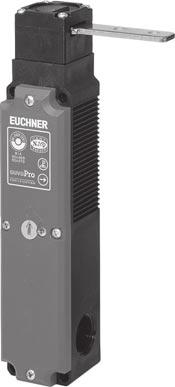
Safety Switches NP GP TP. More than safety.
|
|
|
- Gabriella Griffith
- 5 years ago
- Views:
Transcription


1 Safety Switches NP GP TP More than safety.


2 Safety More than safety. Emil Euchner, the company s founder and inventor of the multiple limit switch, circa Around the world the Swabian specialists in motion sequence control for mechanical and systems engineering. EUCHNER s history began in 1940 with the establishment of an engineering office by Emil Euchner. Since that time, EUCHNER has been involved in the design and development of switchgear for controlling a wide variety of motion sequences in mechanical and systems engineering. In 1953, Emil Euchner founded EUCHNER + Co., a milestone in the company s history. In 1952, he developed the first multiple limit switch to this day a symbol of the enterprising spirit of this familyowned company. Automation Safety ManMachine Today, our products range from electromechanical and electronic components to complex system solutions. With this wide range of products we can provide the necessary technologies to offer the right solution for special requirements regardless of whether these relate to reliable and precise positioning or to components and systems for safety engineering in the automation sector. EUCHNER products are sold through a world-wide sales network of competent partners. With our closeness to the customer and the guarantee of reliable solutions throughout the globe, we enjoy the confidence of customers all over the world. Quality, reliability, precision Quality, reliability and precision are the hallmarks of our corporate philosophy. They represent concepts and values to which we feel totally committed. At EUCHNER, quality means that all our employees take personal responsibility for the company as a whole and, in particular, for their own field of work. This individual commitment to perfection results in products which are ideally tailored to the customers needs and the requirements of the market. After all: our customers and their needs are the focus of all our efforts. Through efficient and effective use of resources, the promotion of personal initiative and courage in finding unusual solutions to the benefit of our customers, we ensure a high level of customer satisfaction. We familiarize ourselves with their needs, requirements and products and we learn from the experiences of our customers own customers. EUCHNER More than safety. Quality made by EUCHNER 2

3 Table of contents Accessories Appendix General Information 4 Safety switches NP.../GP... without guard-locking device 6 Advantages and features 6 Sample applications 7 Series NP... 1, 2 and 3 contact switching elements 8 Series GP... 2 and 4 contact switching elements 10 Safety switches TP... with guard-locking device Advantages and features Operating principle Sample applications 15 Series TP... 2 contact switching elements 16 Series TP...K 2 contact switching elements with increased overtravel 18 Series TP... 4 contact switching elements, without door monitoring contact 20 Series TP...K 4 contact switching elements, without door monitoring contact with increased overtravel Series TP... 4 contact switching elements, with door monitoring contact 24 Series TP...K 4 contact switching elements, with door monitoring contact 26 with increased overtravel Series TP... 3 contact switching elements, with door unlock request contact 28 Special versions 30 Series TP... Switching elements with 4 positively driven NC contacts, with door monitoring contact 30 Series TP... With additional cable entry through the rear mounting face Series TP... With emergency release through the rear mounting face, short actuation axis 32 Series TP... With emergency release through the rear mounting face, long actuation axis Series TP... With M plug connectors Series TP... With 2 M plug connectors 36 Actuators 38 Latch spring for increased retention force Lockout bar Safety screws / Replacement screws Insertion funnel NP/TP Lock Adapter NP-K 43 Built-in LED 43 Cable glands 44 Plug connector with / without connection cable 44 Standard bolt for safety guards 46 Bolt with emergency release for escape from the hazardous area 49 Mounting plates EMP for TP...A Satey Switches 50 Index 51 Technical Status 01-04/04 3
4 General Information Safety switches are safety-related machine control components in accordance with EN and BGI 575. They are designed to safely interrupt the safety circuit or to prevent operation until any danger to the user has been eliminated. Since safety switches prevent the operation of a system under certain conditions (generally for as long as the safety guard remains open), they are also described as interlocking devices. Interlocking devices are available with or without a guard-locking device. According to EN 1088, electromechanical switches with no guardlocking device must be designed so that they positively switch off hazardous movement when safety guards are opened. They also prevent machines from being restarted when the safety guard is open. EUCHNER safety switches NP, GP are examples of an interlocking device without a guard-locking device. In order to ensure that the process is not interrupted by unintentional opening of the safety guard, safety switches with electromechanical guard-locking devices are frequently used for process protection. A guard-locking device can be used for personal protection, if the locking magnet is controlled by a standstill monitor and the safety switch has a fail-safe system for monitoring the solenoid. With the aid of the interlocking monitoring system, EUCHNER safety switch TP meets all the necessary conditions for use for personal protection. Safety switches NP, GP and TP have been designed so that the same actuators can be used for both types of switch. For the design engineer, this offers the advantage of simplicity: If safety switches with and without a guard-locking device are used, only the drilling pattern for the switch needs to be modified. The actuator assembly remains the same. For different applications where hinged and sliding doors are used, EUCHNER offers straight or bent actuators. Actuators with rubber bushings facilitate flexible fastening or bedding of the actuator. Where there is a slight misalignment of the door, the actuator aligns itself to the switch actuator opening. When inserted, spring bearing actuators (so-called hinged actuators) fit almost friction-free. They are suitable for small hinged doors with a minimum radius of 100 mm. In this context, the actuator with overtravel is a particularly interesting example. When the door is closed, this allows a certain amount of play. In the closed state, the door can move slightly in the direction of the actuator. With protective doors this is particularly useful if they have a rubber buffer as a stop. An actuator with overtravel prevents unintentional stopping of the machine when the door or actuator (in the case of the NP, GP switch) springs back. In practice, a misalignment of the protective doors may be noticed when in operation. If preventative action is not taken, the actuator may be driven against the actuator head and damage it when the door is being closed. To protect the actuation head, EUCHNER offers a metal funnel for safety switches NP, GP and TP (see page ). The use of this extra component increases the depth of actuator travel and an overtravel actuatdor does not relieve the system operator from the responsibility of maintaining the protective door alignment at regular intervals. In order to prevent tampering, actuators must be positively connected to the protective door. It should not be possible to break the connection with simple tools. All EUCHNER actuators are supplied with safety screws. The safety screws and both the straight and bent actuator, are made of stainless steel. This material property is particularly necessary for the food and chemical industries where the safety switch requirements are higher. With their highly resistant housing material (PA6, a glass-fiber reinforced thermoplastic) and the high degree of protection IP 67 for safety switches NP, GP and TP, they can be used in the toughest environmental conditions. The actuation head in safety switches NP, GP and TP can easily be changed to any 90 position for the approach direction. Removing the 4 actuation head screws, the opening for the actuation head can be rotated to the required approach direction. If the actuation head is permanent in order to prevent tampering, it can be secured to the housing with safety screws (see chapter on accessories). If an adapter (see page 43) has been installed between the housing and the actuation head, safety switches NP can be tripped from the top by actuators with increased overtravel. The unused actuator opening can be sealed with the cap supplied. With modern wiring concepts there is a trend towards plug-in connections. A switch with plug-connectors can be easily replaced during servicing work. EUCHNER offers safety switches NP and TP with 6-pole and -pole plug connectors. In addition to the relevant mating connectors, connectors with fixed cables are also offered as accessories. Safety switches with M plug connector are available on request. 4

5 Standard aluminum profiles are often used for safety guards. These are becoming increasingly prevalent due to the ease of installation, with a groove profile width of 40 mm and/or 45 mm becoming standard. EUCHNER safety switches NP, GP and TP have the 40 mm width and can be secured flush to the barrier. Specially developed adapter plates (see pages and ) facilitate fast assembly of safety switches TP with the standard profiles. The adapter plates can be used for all standard commercially available profiles. A further move towards standardization was made with the market introduction of bolts (see pages and ). For safety switches NP, GP and TP, EUCHNER offers bolts which can be fastened to standard profiles with little effort. Pre-wired with connectors, safety switches NP, GP and TP can offer maximum protection. The standard safety switches are BG, CAS, SAQ, SUVA and UL approved. Your advantages! Safety switches with separate actuator for protecting safety guards! Fully insulated by glass fiber reinforced thermoplastic! Degree of protection IP 67! 4 Lateral approach directions can be changed quickly and conveniently! 1 Approach direction from top! Rear actuator head opening facilitates removal of dirt! The same actuators can be used for NP, GP and TP switches! Actuators and safety screws are made of stainless steel! Actuators with rubber bushings! Increased actuator overtravel in all directions of approach! Different switching elements available! A number of different connection types are available! Small switch width (NP : 35 mm, GP/TP : 40 mm),! suitable for aluminum profile assembly! Attractive design! Approved by BG, CSA, SAQ, SUVA, UL 5
 with separate actuator for protecting safety guards! Installation in accordance with EN 50047 (NP...AS) or alternatively with 40 mm hole spacing (NP...AB)!")
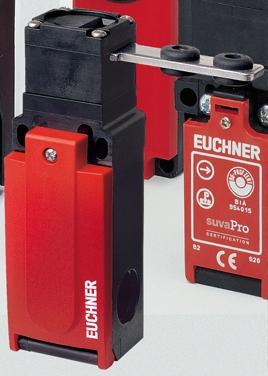
6 Safety switches NP... without guard-locking device -Safety switches in the NP series... offer important advantages! Safety switches (without guard-locking device) with separate actuator for protecting safety guards! Installation in accordance with EN (NP...AS) or alternatively with 40 mm hole spacing (NP...AB)! Small switch width (35 mm)! Ideal for profile assembly! Option: with the adapter set, an upgrade for increased overtravel from the top is available! Switching elements with 1, 2 or 3 contact elements! 10 N Retention force and/or 30 N with latch spring! Connection using cable entry M20 x 1.5 or 6-pole plug connector! Slide bolts available Approach direction can be changed quickly 6
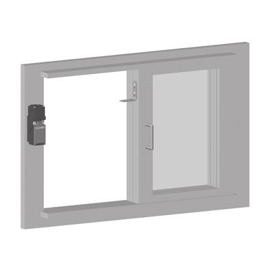
7 Sample applications for safety switches in the NP series... 7
8 Safety switches NP...! With 1, 2 or 3 contact elements! Cable entry M20x1.5 or Plug connector SR6 (relevant plug connectors see page 45) * for cable entry M * * Dimension drawing NP1-AS (Fixing to EN 50047) Insertion depth h Insertion depth Switching elements (dependent action contact element) positively driven NC contact positively driven NC contact + 1 NO contact positively driven NC contacts positively driven NC contacts + 1 NO contact 98 with adapter H = v 20 4,3 Actuator inserted Actuator removed M20x1, Please order actuator separately (see pages 38 to 40). 638 Dimension drawing NP1-AB (40 mm hole spacing) Insertion depth v h 8,5 Insertion depth Installation notes The safety switch and actuator must be installed properly. The actuator must be positively connected with the mounting surface, e.g. by using safety screws (see page ) or by welding, riveting, pinning. The safety switch must not be used as an end stop. 98 with adapter H = ,5 10 Changing the approach direction Upon removal of the actuator head fixing screws, the approach direction can be changed to any 90 increment. The standard setting is approach direction A. 40 A 8 50 M20x1, Please order actuator separately (see pages 38 to 40) ,5 The complete safety switch must be replaced in the event of faults. 8
9 Technical data Parameters Value Unit Housing material Glass fiber reinforced thermoplastic Degree of protection to IEC IP 67 for M20x1.5 / IP 65 for SR6 Mounting position optional Mechanical service life 1 x 10 6 switching cycles Ambient temperature - 20 to +80 C Approach speed, max. 20 m/min Weight approx. 0. kg Switching element Contact elements 1 NC 1 NC + 1 NO 2 NC 2 NC + 1 NO Switching principle Dependent action contact element Contact material Silver alloy Rated impulse withstand voltage U imp 2.5 kv Rated insulation voltage U i NP1: U i = 400 / NP2: U i = 250 V Utilization category to IEC AC-15 Ie 4 A Ue 230 V / DC- Ie 4 A Ue 24 V Switching voltage min. at 10 ma 24 V Switching current min. at 24 V 30 ma Conventional thermal current I th 4 A Short circuit protection (control circuit fuse) to IEC : 4 A gg Connection method NP1... Screw terminal, M20x1.5 Connection method NP2... Plug connector SR6 Connection to switching element Screw terminals, max. cross-section of a single connector 1.5 mm 2 Insertion depth (necessary minimum travel + permissible overtravel) Standard actuator Overtravel actuator Approach direction side (h) mm Approach direction from top (v) Only with adapter NP-K mm / page 45 Dimension drawing NP2... Pin assignment NP2... inserted inserted View of connection side Ordering table Series / Increased Switching Connection type / overelement Installation method travel Article Contact elements NP1...AS-M 618 NP1-618AS-M 1 pos. driven NC Cable entry 628 NP1-628AS-M 1 pos. driven NC + 1 NO Fitting to 638 NP1-638AS-M 2 pos. driven NC EN A NP1-648AS-M 2 pos. driven NC + 1 NO NP1...AB-M 618 (side) NP1-618AB-M 1 pos. driven NC Cable entry 628 NP1-628AB-M 1 pos. driven NC + 1 NO mm 638 NP1-638AB-M 2 pos. driven NC hole spacing 648 NP1-648AB-M 2 pos. driven NC + 1 NO NP2...AS Plug connector SR6 628 NP2-628AS 1 pos. driven NC + 1 NO Fitting to 638 A NP2-638AS 2 pos. driven NC EN (side) NP2...AB 628 NP2-628AB 1 pos. driven NC + 1 NO Plug connector SR6 40 mm hole spacing 638 NP2-638AB 2 pos. driven NC Ordering example: NP1, switching element 638, increased overtravel side A, 40 mm hole spacing (B), cable entry M NP1-638AB-M
10 Safety Switches GP... *! With 2 or 4 contact elements! Cable entry M20x1.5 * Approvals pending Dimension drawing GP1... V h Switching elements positively driven NC contact + 1 NO contact positively driven NC contacts 4 positively driven NC contacts 3 positively driven NC contacts + 1 NO contact 2 positively driven NC contacts + 2 NO contacts ,1 Actuator inserted Actuator removed 5 32 M20 x 1,5 (3x) , Please order actuator separately (see pages 38 to 40). 16 7,5 Assembly instructions The safety switch and actuator must be installed properly. The actuator must be positively connected with the mounting surface, e.g. by using safety screws (see page ) or by welding, riveting, pinning. The safety switch must not be used as an end stop. 8,5 Changing the approach direction Upon removal of the actuating head fixing screws, the approach direction can be changed to any 90 increment. The standard setting is approach direction A. A C B D A In the event of faults, the complete safety switch must be replaced. 10
11 Technical data Parameters Value Unit Housing material Reinforced thermoplastic Degree of protection according to IEC IP 67 Installation position Any Mechanical life 2 x 10 6 operating cycles Ambient temperature - 20 to + 80 C Approach speed, max. 20 m/min Insertion/extraction force 8/25 N Weight Approx kg Switching element Contact elements 1 NC + 1 NO 2 NC 4 NC 3 NC + 1 NO 2 NC + 2 NO Switching principle Slow-action contact element Contact material Silver alloy, gold flashed Rated impulse withstand voltage Uimp 2.5 kv Rated insulation voltage Ui 250 V Utilization category according to IEC AC-15 Ie 4 A Ue 230 V / DC- Ie 4 A Ue 24 V Switching voltage, min. at 10 ma V Switching current, min. at 24 V 1 ma Conventional thermal current Ith 4 A Short circuit protection (control circuit fuse) According to IEC : 4 A gg Connection method GP...M Screw terminal, M20x1.5 Connection to switching element Screw terminals, max. cross-section of a single connector 1.5 mm² Insertion depth Standard actuators Overtravel actuators (necessary minimum travel + permissible overtravel) Approach direction side (h) mm Approach direction from top (v) mm Ordering table Series / Switching Increased Contact Article Connection type element overtravel elements 528 GP1-528A-M 1 positively driven NC contact + 1 NO contact GP1-538A-M 2 positively driven NC contacts GP1...M A GP1-A-M 4 positively driven NC contacts cable entry (side + top) 3 positively driven NC contacts + GP1-A-M 1 NO contact GP1-A-M 2 positively driven NC contacts + 2 NO contacts

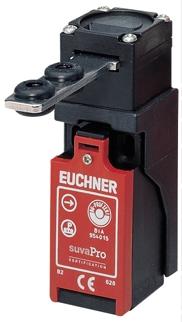
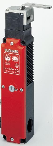
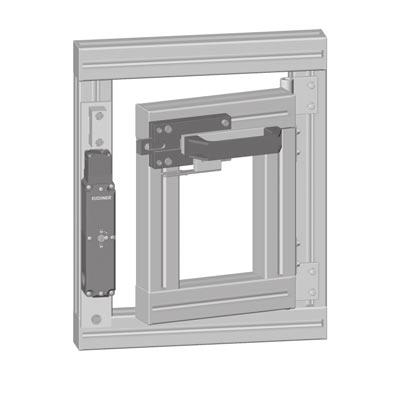
12 Safety switches TP... with guard-locking device EUCHNER safety switch TP has a built-in solenoid (a guard-locking device) which is designed to provide process and personal protection. According to standard EN 1088, switches with a guard-locking device must have a mechanical unlocking mechanism. This mechanism must allow manual unlocking of the guard-locking device from the machine s access side with a suitable tool or key. When the tool or key is removed, the mechanical unlocking mechanism must return automatically to the starting position or remain in a safe position. The mechanical unlocking mechanism for safety switch TP meets these requirements. When delivered, the mechanical unlocking device is sealed to prevent tampering. EUCHNER offers an optional lock as an accessory for the mechanical unlocking mechanism; this can be retro-fitted to the safety switch cover. Authorized personnel can unlock the mechanical unlocking device with a key to interrupt the safety circuit. When the safety switch is unlocked, the operator can access the machine. If the hazardous area behind the safety device can be accessed, measures must be taken to ensure that anyone who is accidentally locked in (e.g. if a door closes to), can automatically free themselves. Safety switches TP have an optional emergency release to the rear that can be operated by a rotary lever. EUCHNER also offers appropriate bolts for such applications (for an exact description see page 49). For safety switches TP, a choice of three M20x1.5 cable entries are available to the user. Depending on the switch alignment, a convenient cable entry can be used. In the case of variant TP...-C1761 (see page ), the switch has an extra cable entry to the rear. This allows the cable to be fed directly to the switch through a drill hole in the safety guard. A flat seal between the rear of the housing and the mounting face protects from the penetration of dirt. Safety switches TP are also available with plug connectors. If an M plug connector (8-pole) is used, it can be connected directly to an AS-Interface or Profisafe module. Safety switches TP... with different contact elements! 2 contact switching elements! 1 NC contact + 1 NO contact! 2 NC contacts! Switching elements with 3 contact elements (with door unlock request contact)! 2 NC contacts + 1 NO contact! 4 contact switching elements! 2 NC contacts + 2 NO contacts! 3 NC contacts + 1 NO contact! 4 NC contacts Switching elements with 4 contact elements offer important advantages! Versatile connection options! Only one switch for several applications! Installation in the conventional EUCHNER housing! No conversion problems! Familiar housing dimensions and drilling pattern! Fewer types! Savings in storage costs! Redundant (twin-channel) integration into the safety circuit through the use of 2 electrically separated positively driven NC contacts. When wiring several safety switches in series, redundant integration into the safety circuit is also possible.! Greater safety for the user! High control category (according to EN 954-1)! Approval for BG, CSA, SAQ, SUVA, UL
!")
13 -Safety switches in the TP series... offer important advantages! Safety switches with separate actuator and guard-locking device for protecting safety guards! Retention force 00 N in locked state! Mechanical auxiliary unlocking mechanism from the front! Mechanical key unlocking mechanism from the front (optional, retro-fit)! Emergency release through the rear mounting face available as an option! User-operated mechanism for emergency escape from hazardous area! A voltage rectifier is placed before the solenoid coil! Voltage peaks are avoided when the solenoid is switched! Large selection of switching elements! Switch with door unlock request contact available! An unlock command can be issued locally without a stop button! 3 cable entries M20 x 1.5 or plug connector (6 or -pole)! Switch with M plug connector suitable for direct connection to AS-Interface Safety at Work module! Slide bolts available Approach direction can be changed quickly
14 Operating principle The sectional drawings show safety switch TP in the three basic positions:! Door closed and locked! Door closed and unlocked! Door open and unlocked Door closed and locked If the solenoid plunger is in the top position (right illustration), this prevents rotation of the cam disc in the actuation head. The actuator or safety guard is therefore locked. When the plunger is in this position, positively driven NC contacts - and - are held in the closed position. This means that the machine protected by the safety circuit can be started. Door closed and unlocked If the solenoid is switched on (in the case of safety switches TP...), the cam disc blocking is lifted and the NC contacts (- and -) are opened at the same time. NO contact - signals that the interlocking solenoid is unlocked. Door open and unlocked When the actuator is being removed, the cam disc is rotated. Because of its eccentric contour, the plunger is pressed fully down. NO contact - closes and sends a signal to the control that the safety guard is open. Since the solenoid plunger and the cam disc are positively connected, the NC contacts - & - remain securely open. This design feature of the guard-locking device ensures that the locking mechanism (solenoid plunger) cannot lock if the safety guard is open. This is also mentioned in BGI 575 Protection Against Unintentional Closing. The state of a switching element can be polled because of the sequential switching pattern (solenoid plunger can adopt three basic positions) In consequence of this technology, EUCHNER s safety switch TP has a slender structural design. It is ideally suited to applications for which small structural switch designs are essential. Door open and unlocked Actuator Door closed and unlocked Door closed and locked +24 V Safety circuit Channel A Channel B Door closed Door locked PLC Output Inputs
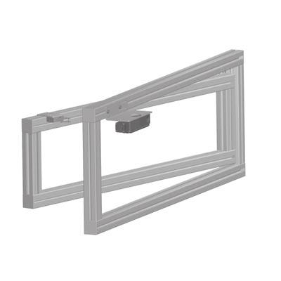
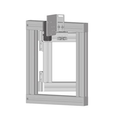
15 Applications for TP... series Safety Switches 15
16 Safety switches TP...! With 2 contact elements! With door monitoring contact for TP3.../TP4...! Cable entry M20x1.5 or Plug connector SR6 (relevant plug connectors see page 45) * * * with cable entry M, 24 V DC / 0 V AC Dimension drawing TP...M 192 Please order actuator separately (see pages 38 to 40) M20x1,5 (3x) 43 4 Dimension drawing TP...SR6 Please order plug connector separately (see page 45). Insertion depth 16 v inserted h ,5 inserted Insertion depth for M5 > 35 mm ISO 07 (DIN 84) ISO 4762 (DIN 9) Mechanical unlocking mechanism Mechanical unlocking screw Switching elements (dependent action contact element) positively driven NC contact + 1 NO contact positively driven NC contact + 1 NC contact as door monitoring contact positively driven NC contacts Actuator inserted Actuator locked unlocked removed Locking methods TP1.../ TP3...: Actuator inserted, mechanically locked, unlock by applying voltage. TP2.../ TP4...: Lock by applying voltage. Mechanical unlocking mechanism Safety switches can be unlocked by using the mechanical unlocking mechanism in the event of power failure, for example. The mechanical unlocking mechanism has to be sealed to prevent tampering (for example with sealing lacquer). Changing the approach direction Upon removal of the actuator head fixing screws, the approach direction can be changed to any 90 increment. The standard setting is approach direction A A Installation notes The safety switch and actuator must be installed properly. The actuator must be positively connected with the mounting surface, e.g. by using safety screws (see page ) or by welding, riveting, pinning. The safety switch must not be used as an end stop. The complete safety switch must be replaced in the event of faults. 16
17 Technical data Parameters Value Unit Housing material Glass fiber reinforced thermoplastic Degree of protection to IEC TP...M: IP 67 / TP...SR6: IP 65 Mounting position optional Mechanical service life 1 x 10 6 switching cycles Ambient temperature - 20 to + 55 C Approach speed, max. 20 m/min Insertion/extraction force (not locked) TP1, TP2: approx. 8 / TP3: approx. 10 / TP4: approx. 15 N Retention force when locked 00 N Weight approx. 0.5 kg Switching element Contact elements 1 NC + 1 NO 1 NC + 1 NC 2 NC Switching principle Dependent action contact element Contact material silver alloy, gold flashed Rated impulse withstand voltage U imp 2.5 kv Rated insulation voltage U i 250 V Utilization category to IEC AC-15 Ie 6 A Ue 230 V / DC- Ie 6 A Ue 24 V Switching voltage min. at 10 ma V Switching current min. at 24 V 10 ma Conventional thermal current I th 6 A Short circuit protection (control circuit fuse) to IEC : 6 A gg Connection method TP...M Screw terminal, M20x1.5 Connection method TP...SR6 Plug connector SR6 Connection to switching element Screw terminals, max. cross-section of a single connector 1.5 mm 2 mm 2 Solenoid Connection reverse polarity protected, integrated bridge rectifier Solenoid operating voltage 24 V AC/DC, 0 V AC, 230 V AC (all -15% / +10%) Duty cycle 100 % Power consumption 8 W Insertion depth (necessary minimum travel + permissible overtravel) Standard actuator Overtravel actuator Approach direction side (h) mm Approach direction from top (v) mm Pin assignment TP...SR View of connection side Solenoid monitoring 2 Solenoid monitoring Door monitoring 2 Solenoid monitoring Solenoid monitoring 2 Solenoid monitoring Ordering table Series / Increased Switching Locking method / over- Article Solenoid operating voltage element Connection type travel TP1-...M / TP3-...M 528 TP1-528A...M Mechanical locking, 537 TP3-537A...M Cable entry 538 A TP1-538A...M TP2-...M / TP4-...M 528 (side) TP2-528A...M Electrical locking, 537 TP4-537A...M Cable entry 538 TP2-538A...M TP1-...SR6 / TP3-...SR6 528 TP1-528A...SR Mechanical locking, 537 TP3-537A...SR Plug connector SR6 538 A TP1-538A...SR TP2-...SR6 / TP4-...SR6 528 (side) TP2-528A...SR Electrical locking, 537 TP4-537A...SR Plug connector SR6 538 TP2-538A...SR Ordering example: TP2, electr. locking, switching element 528, increased overtravel side A, solenoid operating voltage 230 V AC, cable entry M TP2-528 A 230 M
18 Safety switches TP..K..! Increased overtravel with approach direction from top! With 2 contact elements! With door monitoring contact for TP3.../TP4...! Cable entry M20x1.5 or Plug connector SR6 (relevant plug connectors see page 45) * * * with cable entry M, 24 V DC / 0 V AC Dimension drawing TP...M Insertion depth 50 v h Insertion depth for M5 > 35 mm ISO 07 (DIN 84) ISO 4762 (DIN 9) Switching elements (dependent action contact element) positively driven NC contact + 1 NO contact positively driven NC contact + 1 NC contact as door monitoring contact positively driven NC contacts Actuator inserted Actuator locked unlocked removed Mechanical unlocking mechanism M20x1,5 (3x) Mechanical unlocking screw Please order actuator separately (see pages 38 to 40). Dimension drawing TP...SR6 Please order plug connector separately (see page 45). inserted 16 8,5 inserted Locking methods TP1.../ TP3...: Actuator inserted, mechanically locked, unlock by applying voltage. TP2.../ TP4...: Lock by applying voltage. Mechanical unlocking mechanism Safety switches can be unlocked by means of the mechanical unlocking mechanism in the event of power failure, for example. The mechanical unlocking mechanism has to be sealed to prevent tampering (for example with sealing lacquer). Changing the approach direction Upon removal of the actuator head fixing screws, the approach direction an be changed to any 90 increment. The standard setting is approach direction K. K Installation notes The safety switch and actuator must be installed properly. The actuator must be positively connected with the mounting surface, e.g. by using safety screws (see page ) or by welding, riveting, pinning. The safety switch must not be used as an end stop. The complete safety switch must be replaced in the event of faults. 18
19 Technical data Parameters Value Unit Housing material Glass fiber reinforced thermoplastic Degree of protection to IEC TP...M: IP 67 / TP...SR6: IP 65 Mounting position optional Mechanical service life 1 x 10 6 switching cycles Ambient temperature - 20 to + 55 C Approach speed, max. 20 m/min Insertion/extraction force (not locked) approx. 8 N Retention force when locked 00 N Weight approx. 0.5 kg Switching element Contact elements 1 NC + 1 NO 1 NC + 1 NC 2 NC Switching principle Dependent action contact element Contact material silver alloy, gold flashed Rated impulse withstand voltage U imp 2.5 kv Rated insulation voltage U i 250 V Utilization category to IEC AC-15 Ie 6 A Ue 230 V / DC- Ie 6 A Ue 24 V Switching voltage min. at 10 ma V Switching current min. at 24 V 10 ma Conventional thermal current I th 6 A Short circuit protection (control circuit fuse) to IEC : 6 A gg Connection method TP...M Screw terminal, M20x1.5 Connection method TP...SR6 Plug connector SR6 Connection to switching element Screw terminals, max. cross-section of a single connector 1.5 mm 2 mm 2 Solenoid Connection reverse polarity protected, integrated bridge rectifier Solenoid operating voltage 24 V AC/DC, 0 V AC, 230 V AC (all -15% / +10%) Duty cycle 100 % Power consumption 8 W Insertion depth (necessary minimum travel + permissible overtravel) Standard actuator Overtravel actuator Approach direction side (h) mm Approach direction from top (v) mm Pin assignment TP...SR View of connection side Solenoid monitoring 2 Solenoid monitoring Door monitoring 2 Solenoid monitoring Solenoid monitoring 2 Solenoid monitoring Ordering table Series / Increased Switching Locking method / over- Article Solenoid operating voltage element Connection type travel TP1-...M / TP3-...M 528 TP1-528K...M Mechanical locking, 537 TP3-537K...M Cable entry 538 K TP1-538K...M on request TP2-...M / TP4-...M 528 (side + top) TP2-528K...M on request Electrical locking, 537 TP4-537K...M Cable entry 538 TP2-538K...M on request TP1-...SR6 / TP3-...SR6 528 TP1-528K...SR Mechanical locking, 537 TP3-537K...SR Plug connector SR6 538 K TP1-538K...SR TP2-...SR6 / TP4-...SR6 528 (side + top) TP2-528K...SR on request on request Electrical locking, 537 TP4-537K...SR Plug connector SR6 538 TP2-538K...SR Ordering example: TP2, electr. locking, switching element 528, increased overtravel side and top K, solenoid operating voltage 24 V AC/DC, cable entry M TP2-528 K 024 M
20 Safety switches TP...! With 4 contact elements, without door monitoring contact! Cable entry M20x1.5 or Plug connector SR (relevant plug connectors see page 45) * * * with cable entry M, 24 V DC / 0 V AC Dimension drawing TP...M Insertion depth h Insertion depth Switching elements (dependent action contact element) 2 positively driven NC contacts +2 NO contacts Actuator inserted Actuator locked unlocked removed 192 Please order actuator separately (see pages 38 to 40) M20x1,5 (3x) v for M5 > 35 mm ISO 07 (DIN 84) ISO 4762 (DIN 9) Mechanical unlocking mechanism Mechanical unlocking screw Locking methods TP1...: Actuator inserted, mechanically locked, unlock by applying voltage. TP2...: Lock by applying voltage. Mechanical unlocking mechanism Safety switches can be unlocked by means of the mechanical unlocking mechanism in the event of power failure, for example. The mechanical unlocking mechanism has to be sealed to prevent tampering (for example with sealing lacquer). Dimension drawing TP...SR Please order plug connector separately (see page 45). 8,5 Changing the approach direction Upon removal of the actuator head fixing screws, the approach direction can be changed to any 90 increment. The standard setting is approach direction A. A inserted inserted The complete safety switch must be replaced in the event of faults. Installation notes The safety switch and actuator must be installed properly. The actuator must be positively connected with the mounting surface, e.g. by using safety screws (see page ) or by welding, riveting, pinning. The safety switch must not be used as an end stop. 20
21 Technical data Parameters Value Unit Housing material Glass fiber reinforced thermoplastic Degree of protection to IEC TP...M: IP 67 / TP...SR: IP 65 Mounting position optional Mechanical service life 1 x 10 6 switching cycles Ambient temperature - 20 to + 55 C Approach speed, max. 20 m/min Insertion/extraction force (not locked) approx. 8 N Retention force when locked 00 N Weight approx. 0.5 kg Switching element Contact elements 2 NC + 2 NO Switching principle Dependent action contact element Contact material silver alloy, gold flashed Rated impulse withstand voltage U imp TP...M: U imp = 2.5 / TP...SR: U imp = 1,5 kv Rated insulation voltage U i TP...M: U i = 250 / TP...SR: U i = 50 V Utilization category to IEC TP...M: AC-15 Ie 6 A Ue 230 V / DC- Ie 6 A Ue 24 V TP...SR: AC-15 Ie 4 A Ue 50 V / DC- Ie 4 A Ue 24 V Switching voltage min. at 10 ma V Switching current min. at 24 V 10 ma Conventional thermal current I th TP...M: 6 / TP...SR: 4 A Short circuit protection (control circuit fuse) to IEC , TP...M: 6 A gg / TP...SR: 4 A gg Connection method TP...M Screw terminal, M20x1.5 Connection method TP...SR Plug connector SR Connection to switching element Screw terminals, max. cross-section of a single connector 1.5 mm 2 mm 2 Solenoid Connection reverse polarity protected, integrated bridge rectifier Solenoid operating voltage 24 V AC/DC, 0 V AC, 230 V AC (all -15% / +10%) Duty cycle 100 % Power consumption 8 W Insertion depth (necessary minimum travel + permissible overtravel) Standard actuator Overtravel actuator Approach direction side (h) mm Approach direction from top (v) mm Pin assignment TP...SR 9 View of connection side Solenoid monitoring 6 Solenoid monitoring 4 Solenoid monitoring 2 Solenoid monitoring Ordering table Series / Increased Switching Locking method / over- Article Solenoid operating voltage element Connection type travel TP1-...M Mechanical locking, TP1-A...M Cable entry A TP2-...M (side) Electrical locking, TP2-A...M Cable entry TP1-...SR Mechanical locking, TP1-A...SR Plug connector SR A TP2-...SR (side) Electrical locking, TP2-A...SR Plug connector SR Ordering example: TP2, electr. locking, switching element, increased overtravel side A, solenoid operating voltage 024 V AC/DC, cable entry M TP2- A 024 M 084 5
22 Safety switches TP..K..! Increased overtravel with approach direction from top! With 4 contact elements, without door monitoring contact! Cable entry M20x1.5 or Plug connector SR (relevant plug connectors see page 45) * * * with cable entry M, 24 V DC / 0 V AC Dimension drawing TP...M Insertion depth h Insertion depth Switching elements (dependent action contact element) 2 positively driven NC contacts +2 NO contacts Actuator inserted Actuator locked unlocked removed v for M5 > 35 mm ISO 07 (DIN 84) ISO 4762 (DIN 9) Mechanical unlocking mechanism M20x1,5 (3x) Mechanical unlocking screw Locking methods TP1...: Actuator inserted, mechanically locked, unlock by applying voltage. TP2...: Lock by applying voltage. Please order actuator separately (see pages 38 to 40) Mechanical unlocking mechanism Safety switches can be unlocked by means of the mechanical unlocking mechanism in the event of power failure, for example. The mechanical unlocking mechanism has to be sealed to prevent tampering (for example with sealing lacquer). Dimension drawing TP...SR Please order plug connector separately (see page 45). 8,5 Changing the approach direction Upon removal of the actuator head fixing screws, the approach direction can be changed to any 90 increment. The standard setting is approach direction K. K inserted inserted The complete safety switch must be replaced in the event of faults. Installation notes The safety switch and actuator must be installed properly. The actuator must be positively connected with the mounting surface, e.g. by using safety screws (see page ) or by welding, riveting, pinning. The safety switch must not be used as an end stop.
23 Technical data Parameters Value Unit Housing material Glass fiber reinforced thermoplastic Degree of protection to IEC TP...M: IP 67 / TP...SR: IP 65 Mounting position optional Mechanical service life 1 x 10 6 switching cycles Ambient temperature - 20 to + 55 C Approach speed, max. 20 m/min Insertion/extraction force (not locked) approx. 8 N Retention force when locked 00 N Weight approx. 0.5 kg Switching element Contact elements 2 NC + 2 NO Switching principle Dependent action contact element Contact material silver alloy, gold flashed Rated impulse withstand voltage Uimp TP...M: Uimp = 2.5 / TP...SR: Uimp = 1,5 kv Rated insulation voltage Ui TP...M: Ui = 250 / TP...SR: Ui = 50 V Utilization category to IEC TP...M: AC-15 Ie 6 A Ue 230 V / DC- Ie 6 A Ue 24 V TP...SR: AC-15 Ie 4 A Ue 50 V / DC- Ie 4 A Ue 24 V Switching voltage min. at 10 ma V Switching current min. at 24 V 10 ma Conventional thermal current Ith TP...M: 6 / TP...SR: 4 A Short circuit protection (control circuit fuse) to IEC , TP...M: 6 A gg / TP...SR: 4 A gg Connection method TP...M Screw terminal, M20x1.5 Connection method TP...SR Plug connector SR Connection to switching element Screw terminals, max. cross-section of a single connector 1.5 mm 2 mm 2 Solenoid Connection reverse polarity protected, integrated bridge rectifier Solenoid operating voltage 24 V AC/DC, 0 V AC, 230 V AC (all -15% / +10%) Duty cycle 100 % Power consumption 8 W Insertion depth (necessary minimum travel + permissible overtravel) Standard actuator Overtravel actuator Approach direction side (h) mm Approach direction from top (v) mm Pin assignment TP...SR 9 View of connection side Solenoid monitoring 6 Solenoid monitoring 4 Solenoid monitoring 2 Solenoid monitoring Ordering table Series / Increased Switching Locking method / over- Article Solenoid operating voltage element Connection type travel TP1-...M Mechanical locking, TP1-K...M Cable entry K TP2-...M (side + top) on request on request Electrical locking, TP2-K...M Cable entry TP1-...SR Mechanical locking, TP1-K...SR Plug connector SR K TP2-...SR (side + top) Electrical locking, TP2-K...SR Plug connector SR Ordering example: TP2, electr. locking, switching element, increased overtravel side and top K, solenoid operating voltage 024 V AC/DC, cable entry M TP2- K 024 M
24 Safety switches TP...! With 4 contact elements! With door monitoring contact! Cable entry M20x1.5 or Plug connector SR (relevant plug connectors see page 45) * * * with cable entry M, 24 V DC / 0 V AC Dimension drawing TP...M 192 Please order actuator separately (see pages 38 to 40) M20x1,5 (3x) Insertion depth v h Insertion depth for M5 > 35 mm ISO 07 (DIN 84) ISO 4762 (DIN 9) Mechanical unlocking mechanism Mechanical unlocking screw Switching elements (dependent action contact element) 2 positively driven NC contacts + 1 NO contact + 1 NO contact as door monitoring contact 2 positively driven NC contacts + 1 NO contact + 1 NC contact as door monitoring contact 2 positively driven NC contacts + 1 NC / 1 NO contact as door monitoring contact Actuator inserted Actuator locked unlocked removed Dimension drawing TP...SR Please order plug connector separately (see page 45). 8,5 Locking methods TP3...: Actuator inserted, mechanically locked, unlock by applying voltage. TP4...: Lock by applying voltage. Mechanical unlocking mechanism Safety switches can be unlocked by means of the mechanical unlocking mechanism in the event of power failure, for example. The mechanical unlocking mechanism has to be sealed to prevent tampering (for example with sealing lacquer). inserted inserted Changing the approach direction Upon removal of the actuator head fixing screws, the approach direction can be changed to any 90 increment. The standard setting is approach direction A. A Installation notes The safety switch and actuator must be installed properly. The actuator must be positively connected with the mounting surface, e.g. by using safety screws (see page ) or by welding, riveting, pinning. The safety switch must not be used as an end stop. The complete safety switch must be replaced in the event of faults. 24
25 Technical data Parameters Value Unit Housing material Glass fiber reinforced thermoplastic Degree of protection to IEC TP...M: IP 67 / TP...SR: IP 65 Mounting position optional Mechanical service life 1 x 10 6 switching cycles Ambient temperature - 20 to + 55 C Approach speed, max. 20 m/min Insertion/extraction force (not locked) TP3: approx. 10 / TP4: approx. 15 N Retention force when locked 00 N Weight approx. 0.5 kg Switching element Contact elements 2 NC + 1 NO + 1 NO 2 NC + 1 NO + 1 NC 2 NC Switching principle Dependent action contact element + 1 NC + 1 NO Contact material silver alloy, gold flashed Rated impulse withstand voltage Uimp TP...M: Uimp = 2.5 / TP...SR: Uimp = 1.5 kv Rated insulation voltage Ui TP...M: Ui = 250 / TP...SR: Ui = 50 V Utilization category to IEC TP...M: AC-15 Ie 6 A Ue 230 V / DC- Ie 6 A Ue 24 V TP...SR: AC-15 Ie 4 A Ue 50 V / DC- Ie 4 A Ue 24 V Switching voltage min. at 10 ma V Switching current min. at 24 V 10 ma Conventional thermal current Ith TP...M: 6 / TP...SR: 4 A Short circuit protection (control circuit fuse) to IEC , TP...M: 6 A gg / TP...SR: 4 A gg Connection method TP...M Screw terminal, M20x1.5 Connection method TP...SR Plug connector SR Connection to switching element Screw terminals, max. cross-section of a single connector 1.5 mm 2 mm 2 Solenoid Connection reverse polarity protected, integrated bridge rectifier Solenoid operating voltage 24 V AC/DC, 0 V AC, 230 V AC (all -15% / +10%) Duty cycle 100 % Power consumption 8 W Insertion depth (necessary minimum travel + permissible overtravel) Standard actuator Overtravel actuator Approach direction side (h) mm Approach direction from top (v) mm Pin assignment TP...SR View of connection side Solenoid monitoring Solenoid monitoring Solenoid monitoring Door monitoring Solenoid monitoring Solenoid monitoring Solenoid monitoring Door monitoring Solenoid monitoring 6 Door monitoring 4 Solenoid monitoring 2 Door monitoring Ordering table Series / Increased Switching Locking method / over- Article Solenoid operating voltage element Connection type travel TP3-...M TP3-A...M Mechanical locking, TP3-2A...M Cable entry A TP3-A...M TP4-...M (side) TP4-A...M Electrical locking, TP4-A...M Cable entry TP4-A...M TP3-...SR TP3-A...SR Mechanical locking, TP3-A...SR Plug connector SR A TP3-A...SR TP4-...SR (side) TP4-A...SR Electrical locking, TP4-A...SR Plug connector SR TP4-A...SR Ordering example: TP4, electr. locking, switching element, increased overtravel side A, solenoid operating voltage 024 V AC/DC, cable entry M TP4- A 024 M
26 Safety switches TP..K..! Increased overtravel with approach direction from top! With 4 contact elements, with door monitoring contact! Cable entry M20x1.5 or Plug connector SR (relevant plug connectors see page 45) * * * with cable entry M, 24 V DC / 0 V AC Dimension drawing TP...M Insertion depth 50 v h Insertion depth Switching elements (dependent action contact element) 2 positively driven NC contacts + 1 NO contact + 1 NO contact as door monitoring contact 2 positively driven NC contacts + 1 NO contact + 1 NC contact as door monitoring contact 2 positively driven NC contacts + 1 NC / 1 NO contact as door monitoring contact for M5 > 35 mm ISO 07 (DIN 84) ISO 4762 (DIN 9) Actuator inserted Actuator locked unlocked removed Mechanical unlocking mechanism M20x1,5 (3x) Mechanical unlocking screw Please order actuator separately (see pages 38 to 40) Dimension drawing TP...SR 8,5 Locking methods TP3...: Actuator inserted, mechanically locked, unlock by applying voltage. TP4...: Lock by applying voltage. Please order plug connector separately (see page 45). inserted inserted Mechanical unlocking mechanism Safety switches can be unlocked by means of the mechanical unlocking mechanism in the event of power failure, for example. The mechanical unlocking mechanism has to be sealed to prevent tampering (for example with sealing lacquer). Changing the approach direction Upon removal of the actuator head fixing screws, the approach direction can be changed to any 90 increment. The standard setting is approach direction K. K Installation notes The safety switch and actuator must be installed properly. The actuator must be positively connected with the mounting surface, e.g. by using safety screws (see page ) or by welding, riveting, pinning. The safety switch must not be used as an end stop. The complete safety switch must be replaced in the event of faults. 26
27 Technical data Parameters Value Unit Housing material Glass fiber reinforced thermoplastic Degree of protection to IEC TP...M: IP 67 / TP...SR: IP 65 Mounting position optional Mechanical service life 1 x 10 6 switching cycles Ambient temperature - 20 to + 55 C Approach speed, max. 20 m/min Insertion/extraction force (not locked) TP3: approx. 10 / TP4: approx. 15 N Retention force when locked 00 N Weight approx. 0.5 kg Switching element Contact elements 2 NC + 1 NO + 1 NO 2 NC + 1 NO + 1 NC 2 NC + 1 NC + 1 NO Switching principle Dependent action contact element Contact material silver alloy, gold flashed Rated impulse withstand voltage Uimp TP...M: Uimp = 2.5 / TP...SR: Uimp = 1.5 kv Rated insulation voltage Ui TP...M: Ui = 250 / TP...SR: Ui = 50 V Utilization category to IEC TP...M: AC-15 Ie 6 A Ue 230 V / DC- Ie 6 A Ue 24 V TP...SR: AC-15 Ie 4 A Ue 50 V / DC- Ie 4 A Ue 24 V Switching voltage min. at 10 ma V Switching current min. at 24 V 10 ma Conventional thermal current Ith TP...M: 6 / TP...SR: 4 A Short circuit protection (control circuit fuse) to IEC , TP...M: 6 A gg / TP...SR: 4 A gg Connection method TP...M Screw terminal, M20x1.5 Connection method TP...SR Plug connector SR Connection to switching element Screw terminals, max. cross-section of a single connector 1.5 mm 2 mm 2 Solenoid Connection reverse polarity protected, integrated bridge rectifier Solenoid operating voltage 24 V AC/DC, 0 V AC, 230 V AC (all -15% / +10%) Duty cycle 100 % Power consumption 8 W Insertion depth (necessary minimum travel + permissible overtravel) Standard actuator Overtravel actuator Approach direction side (h) mm Approach direction from top (v) mm Pin assignment TP...SR View of connection side Solenoid monitoring Solenoid monitoring Solenoid monitoring Door monitoring Solenoid monitoring Solenoid monitoring Solenoid monitoring Door monitoring Solenoid monitoring 6 Door monitoring 4 Solenoid monitoring 2 Door monitoring Ordering table Series / Increased Switching Locking method / over- Article Solenoid operating voltage element Connection type travel TP3-...M TP3-K...M Mechanical locking, TP3-K...M Cable entry K TP3-K...M TP4-...M (side + top) TP4-K...M on request Electrical locking, TP4-K...M on request Cable entry TP4-K...M TP3-...SR TP3-K...SR Mechanical locking, TP3-K...SR Plug connector SR K TP3-K...SR TP4-...SR (side + top) TP4-K...SR Electrical locking, TP4-K...SR Plug connector SR TP4-K...SR Ordering example: TP4, electr. locking, switching element, increased overtravel side and top K, solenoid operating voltage 024 V AC/DC, cable entry M TP4- K 024 M
28 Safety switches TP...! With door unlock request contact! With 3 contact elements! Cable entry M20x1.5 or Plug connector SR (relevant plug connectors see page 45) Dimension drawing TP...M 192 Please order actuator separately (see pages 38 to 40) M20x1,5 (3x) Insertion depth Dimension drawing TP...SR v h ,5 Insertion depth for M5 > 35 mm ISO 07 (DIN 84) ISO 4762 (DIN 9) Auxiliary actuation Locking screw Switching elements (dependent action contact element) 40 1 positively driven NC contact as door unlock request contact 1 positively driven NC contact + 1 NO contact (no door monitoring contact) Actuator fully Actuator inserted removed Closed Request Locked Locking methods TP5...: Actuator inserted, mechanically locked, unlock by applying voltage. TP6...: Lock by applying voltage. Door unlock request contact The unlock request contact - is operated if the door together with the actuator is moved slightly away from its closed position. This action opens the - contact, which can then be used via the PLC to unlock the solenoid. The door can then be opened in the normal way. This procedure ensures that the control concepts such as run down and safe speed monitoring can still be adhered to. Please order plug connector separately (see page 45). Auxiliary actuation Used to manually operate the switch element. The - positively driven contact can be opened but the safety guard remains locked. inserted inserted Changing the approach direction Upon removal of the actuator head fixing screws, the approach direction can be changed to any 90 increment. The standard setting is approach direction A. A Installation notes The safety switch and actuator must be installed properly. The actuator must be positively connected with the mounting surface, e.g. by using safety screws (see page ) or by welding, riveting, pinning. The safety switch must not be used as an end stop. The complete safety switch must be replaced in the event of faults. 28
29 Technical data Parameter Value Unit Housing material Glass fiber reinforced thermoplastic Degree of protection to IEC TP...M: IP 67 / TP...SR: IP 65 Mounting position optional Mechanical service life 5 x 10 5 switching cycles Ambient temperature - 20 to + 55 C Approach speed, max. 20 m/min Insertion/extraction force (not locked) approx. 8 N Retention force when locked 800 N Weight approx. 0.5 kg Switching element 40 Contact elements 1 NC + 1 NC + 1 NO Switching principle Dependent action contact element Contact material silver alloy, gold flashed Rated impulse withstand voltage Uimp TP...M: Uimp = 2.5 / TP...SR: Uimp = 1.5 kv Rated insulation voltage Ui TP...M: Ui = 250 / TP...SR: Ui = 50 V Utilization category to IEC TP...M: AC-15 Ie 6 A Ue 230 V / DC- Ie 6 A Ue 24 V TP...SR: AC-15 Ie 4 A Ue 50 V / DC- Ie 4 A Ue 24 V Switching voltage min. at 10 ma V Switching current min. at 24 V 10 ma Conventional thermal current Ith TP...M: 6 / TP...SR: 4 A Short circuit protection (control circuit fuse) to IEC , TP...M: 6 A gg / TP...SR: 4 A gg Connection method TP...M Screw terminal, M20x1.5 Connection method TP...SR Plug connector SR Connection to switching element Screw terminals, max. cross-section of a single connector 1.5 mm 2 mm 2 Solenoid Connection reverse polarity protected, integrated bridge rectifier Solenoid operating voltage 24 V AC/DC, 0 V AC, 230 V AC (all -15% / +10%) Duty cycle 100 % Power consumption 8 W Insertion depth (necessary minimum travel + permissible overtravel) Standard actuator Overtravel actuator Approach direction side (h) mm Approach direction from top (v) mm Pin assignment TP...SR 9 View of connection side Solenoid monitoring 4 Door unlock request contact 2 Solenoid monitoring Ordering table Series / Increased Switching Locking method / over- Article Solenoid operating voltage element Connection type travel TP5-...M Mechanical locking, TP5-40A...M Cable entry A 40 TP6-...M (side) on request on request Electrical locking, TP6-40A...M Cable entry TP5-...SR Mechanical locking, TP5-40A...SR Plug connector SR A 40 TP6-...SR (side) on request on request on request Electrical locking, TP6-40A...SR Plug connector SR Ordering example: TP6, electr. locking, switching element 40, increased overtravel side A, solenoid operating voltage 024 V AC/DC, cable entry M TP6-40 A 024 M
30 Safety switches TP...! With 4 positively driven NC contacts! With door monitoring contact! Cable entry M20x1.5 * * Approvals pending Dimension drawing TP...M h Insertion depth Technical data As for standard version (see pages 16-28) Please order actuator separately (see pages 38 to 40). Pin assignment TP...SR 35 M20x1,5 (3x) Insertion depth v ,5 9 for M5 > 35 mm ISO 07 (DIN 84) ISO 4762 (DIN 9) Mechanical unlocking mechanism Mechanical unlocking screw Switching elements (dependent action contact element) 2 positively driven NC contacts (solenoid monitoring), 2 positively driven NC contacts (door monitoring) Actuator inserted Actuator locked unlocked removed Locking methods TP3...: Actuator inserted, mechanically locked, unlock by applying voltage. TP4...: Lock by applying voltage. Mechanical unlocking mechanism Safety switches can be unlocked by means of the mechanical unlocking mechanism in the event of power failure, for example. The mechanical unlocking mechanism has to be sealed to prevent tampering (for example with sealing lacquer). 32 View of connection side Solenoid monitoring 6 Door monitoring 4 Solenoid monitoring 2 Door monitoring Ordering table Series / Increased Switching Locking method / over- Article Solenoid operating voltage element Connection type travel 024 TP3-...M Mechanical locking, TP3-A024M Cable entry TP4-...M Electrical locking, TP4-A024M Cable entry A TP3-...SR (seitlich) Mechanical locking, TP3-A024SR Plug connector SR TP4-...SR Electrical locking, TP4-A024SR Plug connector SR 30
31 Safety switches TP...! With additional cable entry through the rear mounting face! With 4 contact elements, with door monitoring contact! Cable entry M20x1.5 Dimension drawing TP...M C1761 Insertion depth 43 v h Insertion depth Technical data As for standard version (see pages 16-28). Deviation from standard! Opening in the rear of housing for a cable gland. A flat seal between the rear housing and the mounting face prevents the ingress of dirt M20x1,5 (3x) 4 for M5 > 35 mm ISO 07 (DIN 84) ISO 4762 (DIN 9) Auxiliary unlocking mechanism Mechanical unlocking screw Switching elements (dependent action contact element) 2 positively driven NC contacts + 1 NO contact + 1 NO contact as door monitoring contact 2 positively driven NC contacts + 1 NO contact + 1 NC contact as door monitoring contact 2 positively driven NC contacts +1 NC contact / 1 NO contact as door monitoring contact 18 Actuator inserted Actuator locked unlocked removed Flat seal 16 Please order actuator separately (see pages 38 to 40). 8, Locking methods TP3...: Actuator inserted, mechanically locked, unlock by applying voltage. TP4...: Lock by applying voltage. Ordering table (further types available on request) Series / Increased Switching Locking method / over- Article Solenoid operating voltage element Connection type travel 024 TP3-...M A Mechanical locking, TP3-A024M C (side) Cable entry Ordering example: TP3, Mech. locking, switching element, increased overtravel side A, solenoid operating voltage 024 V AC/DC, cable entry M TP3- A 024 M C
32 Safety switches TP...! Emergency release through the rear mounting face! Short actuation axis! With 4 contact elements, with door monitoring contact! Cable entry M20x1.5 * * Approval with switching element pending Dimension drawing TP...M C1743 Insertion depth h Insertion depth Technical data As for standard version (see pages 16-28). Deviation from standard! Emergency release through the rear mounting face with marked ON/OFF position ,5 M4 v Emergency release Norm. position Released 4 for M5 > 35 mm ISO 07 (DIN 84) ISO 4762 (DIN 9) Mechanical unlocking mechanism Mechanical unlocking screw Switching elements (dependent action contact element) 2 positively driven NC contacts + 1 NO contact + 1 NO contact as door monitoring contact 2 positively driven NC contacts + 1 NO contact + 1 NC contact as door monitoring contact 2 positively driven NC contacts +1 NC contact / 1 NO contact as door monitoring contact 2 positively driven NC contacts (solenoid monitoring), 2 positively driven NC contacts (door monitoring) Actuator inserted Actuator locked unlocked removed M20x1,5 (3x) Please order actuator separately (see pages 38 to 40). 8, Ordering table (further types available on request) Locking methods TP3...: Actuator inserted, mechanically locked, unlock by applying voltage. TP4...: Lock by applying voltage. Series / Increased Switching Locking method / over- Article Solenoid operating voltage element Connection type travel 024 TP3-...M TP3-A024M C A Mechanical locking, TP3-A024M C (side) Cable entry TP3-A024M C Ordering example: TP3, Mech. locking, switching element, increased overtravel side A, solenoid operating voltage 024 V AC/DC, cable entry M TP3- A 024 M C1743 Cat no
33 Safety switches TP...! Emergency release through the rear mounting face! Long actuation axis! With 4 contact elements, with door monitoring contact! Cable entry M20 x 1.5 Dimension drawing TP...M C Insertion depth v h Insertion depth Technical data As for standard version (see pages 16-28). Deviation from standard! The switch with a long actuation axis is suitable for fixing directly to 40 mm wide aluminum profiles. It can be used in combination with bolt TP-.F (see page 49) , ,7 67,5 Emergency release Norm. position M4 Released 4 for M5 > 35 mm ISO 07 (DIN 84) ISO 4762 (DIN 9) Auxiliary unlocking mechanism Locking screw Switching elements (dependent action contact element) 2 positively driven NC contacts + 1 NO contact + 1 NO contact as door monitoring contact 2 positively driven NC contacts + 1 NO contact + 1 NC contact as door monitoring contact 2 positively driven NC contacts +1 NC contact / 1 NO contact as door monitoring contact Actuator inserted Actuator locked unlocked removed M20x1,5 (3x) Please order actuator separately (see pages 38 to 40). 8, Locking methods TP3...: Actuator inserted, mechanically locked, unlock by applying voltage. TP4...: Lock by applying voltage. Ordering table (further types available on request) Series / Increased Switching Locking method / over- Article Solenoid operating voltage element Connection type travel 024 TP3-...M A Mechanical locking, TP3-A024M C (side) Cable entry Ordering example: TP3, Mech. locking, switching element, increased overtravel side A, solenoid operating voltage 024 V AC/DC, cable entry M TP3- A 024 M C1993 Cat no
34 Safety switches TP...! With 3 positively driven NC contacts (fed out through M plug connector)! With door monitoring contact! M plug connector (relevant plug connectors see page 44) * * Approval pending Dimension drawing TP...M C1992 Insertion depth h Insertion depth Deviation from standard! An M 8-pole plug connector is used for connection to safety switch TP...C1992. This switch version is suitable for direct connection to a safe bus module v for M5 > 35 mm ISO 07 (DIN 84) ISO 4762 (DIN 9) Mechanical unlocking mechanism Switching elements (dependent action contact element) H 2 positively driven NC contacts (solenoid monitoring), 2 positively driven NC contacts (door monitoring) Actuator inserted Actuator locked unlocked removed M20x1,5 (2x) Mechanical unlocking screw H Locking methods TP3...: Actuator inserted, mechanically locked, unlock by applying voltage. TP4...: Lock by applying voltage. Please order actuator separately (see pages 38 to 40). 16 8,5 Mechanical unlocking mechanism Safety switches can be unlocked by means of the mechanical unlocking mechanism in the event of power failure, for example. The mechanical unlocking mechanism has to be sealed to prevent tampering (for example with sealing lacquer). Changing the approach direction Upon removal of the actuator head fixing screws, the approach direction can be changed to any 90 increment. The standard setting is approach direction A. Installation notes The safety switch and actuator must be assembled properly. The actuator must be positively connected with the mounting surface, e.g. by using safety screws (see page ) or by welding, riveting, pinning. The safety switch must not be used as an end stop. A The complete safety switch must be replaced in the event of faults.
35 Technical data Parameters Value Unit Housing material Glass fiber reinforced thermoplastic Degree of protection to IEC IP 67 Mounting position optional Mechanical service life 1 x 10 6 switching cycles Ambient temperature - 20 to + 55 C Approach speed, max. 20 m/min Insertion/extraction force (not locked) TP3: approx.10 / TP4: approx. 15 N Retention force when locked 00 N Weight approx. 0.5 kg Switching element H Contact elements 2 NC + 2 NC Switching principle Dependent action contact element Contact material silver alloy, gold flashed Rated impulse withstand voltage Uimp 1,5 kv Rated insulation voltage Ui 30 V Utilization category to IEC AC-15 Ie 1 A Ue 24 V / DC- Ie 1 A Ue 24 V Switching voltage min. at 10 ma V Switching current min. at 24 V 1 ma Conventional thermal current Ith 1 A Short circuit protection (control circuit fuse) to IEC : 1 A gg Connection method M plug connector Connection to switching element Screw terminals, max. cross-section of a single connector 1.5 mm 2 mm 2 Solenoid Connection reverse polarity protected, integrated bridge rectifier Solenoid operating voltage 24 V AC/DC (all -15% / +10%) Duty cycle 100 % Power consumption 8 W Insertion depth (necessary minimum travel + permissible overtravel) Standard actuator Overtravel actuator Approach direction side (h) mm Approach direction from top (v) mm Pin assignment TP...C1992 View of connection side H Solenoid monitoring 4 Solenoid monitoring 2 Door monitoring Ordering table (further types available on request) Series / Increased Switching Locking method / over- Article Solenoid operating voltage element Connection type travel 024 TP3-...M Mechanical locking, TP3-HA024SM8 C M plug connector A H TP4-...M (side) Electrical locking, TP4-HA024SM8 C M plug connector Ordering example: TP3, Mech. locking, switching element H, increased overtravel side A, solenoid operating voltage 024 V AC/DC, M plug connector TP3-H A 024 SM8 C
36 Safety switches TP...! With 2 positively driven NC contacts (fed out through C2 plug connector)! With door monitoring contact! 2 M plug connectors (4-pole) Dimension drawing TP...M C20 (M plug connector right) Insertion depth h Insertion depth Deviation from standard! Two M 4-pole plug connectors are used for connection to safety switches TP...C20 and TP...C20. This switch version is suitable for direct connection to a safe bus module for example v for M5 > 35 mm ISO 07 (DIN 84) ISO 4762 (DIN 9) Mechanical unlocking mechanism 192 Switching elements (dependent action contact element) H 2 positively driven NC contacts (solenoid monitoring), 2 positively driven NC contacts (door monitoring) Actuator inserted Actuator locked unlocked removed 18 4 Mechanical unlocking screw M20x1, H Plug connector C Plug connector C1 16 Locking methods TP3...: Actuator inserted, mechanically locked, unlock by applying voltage. TP4...: Lock by applying voltage. Please order actuator separately (see pages 38 to 40). 16 8,5 Mechanical unlocking mechanism Safety switches can be unlocked by means of the mechanical unlocking mechanism in the event of power failure, for example. The mechanical unlocking mechanism has to be sealed to prevent tampering (for example with sealing lacquer). Changing the approach direction Upon removal of the actuator head fixing screws, the approach direction can be changed to any 90 increment. The standard setting is approach direction A. Plug connector alignment Plug connector C2 is aligned so that the cable exits downwards in the case of an angled M plug connector. Plug connector C1 is not aligned. Installation notes The safety switch and actuator must be assembled properly. The actuator must be positively connected with the mounting surface, e.g. by using safety screws (see page ) or by welding, riveting, pinning. The safety switch must not be used as an end stop. A The complete safety switch must be replaced in the event of faults. 36
37 Technical data Parameters Value Unit Housing material Glass fiber reinforced thermoplastic Degree of protection to IEC IP 67 Mounting position optional Mechanical service life 1 x 10 6 switching cycles Ambient temperature - 20 to + 55 C Approach speed, max. 20 m/min Insertion/extraction force (not locked) approx. 10 N Retention force when locked 00 N Weight approx. 0.5 kg Switching element H Contact elements 2 NC + 2 NC Switching principle Dependent action contact element Contact material silver alloy, gold flashed Rated impulse withstand voltage Uimp 2.5 kv Rated insulation voltage Ui 250 V Utilization category to IEC AC-15 Ie 1.5 A Ue 230 V / DC- Ie 1.5 A Ue 24 V Switching voltage min. at 10 ma V Switching current min. at 24 V 1 ma Conventional thermal current Ith 2 A Short circuit protection (control circuit fuse) to IEC : 2 A gg Connection method 2 M plug connectors Connection to switching element Screw terminals, max. cross-section of a single connector 1.5 mm 2 mm 2 Solenoid Connection reverse polarity protected, integrated bridge rectifier Solenoid operating voltage 24 V AC/DC, 0 V AC, 230 V AC (all -15% / +10%) Duty cycle 100 % Power consumption 8 W Insertion depth (necessary minimum travel + permissible overtravel) Standard actuator Overtravel actuator Approach direction side (h) mm Approach direction from top (v) mm Pin assignment TP...C20 / TP...C20 C1.4 View of connection side of plug connector C1 and C H C2.3 C C1.3 C2.4 Solenoid monitoring C2.2 Door monitoring Ordering table (further types available on request) Series / Increased Switching Locking method / over- Article Solenoid operating voltage element Connection type travel 024 TP3-...C20 Mechanical locking, TP3-HA024SM4C M plug connector left TP4-...C20 A Electrical locking, H (seitlich) M plug connector left TP4-HA024SM4C TP3-...C20 Mechanical locking, TP3-HA024SM4C M plug connector right Ordering example: TP3, Mech. locking, switching element H, increased overtravel side A, solenoid operating voltage 024 V DC, left M plug connector TP3-H A 024 SM4 C
38 Accessories Standard actuators Straight actuator (incl. 2 safety screws M5x10) Article Actuator-P-G Bent actuator (incl. 2 safety screws M5x10) Article Actuator-P-W Min. door radius 1000 mm Min. door radius 1000 mm Hinged actuator for top and bottom hinged doors (incl. 2 safety screws M5x25) Article Hinged actuator P-OU Adjustment screw Adjustment screw Min. door radius 90 mm Hinged actuator for right and left hinged doors (incl. 2 safety screws M5x10) Article Hinged actuator P-LR Adjustment screw Adjustment screw Min. door radius 100 mm 38
39 Overtravel actuators Straight actuator (incl. 2 safety screws M5x10) Article Actuator-P-GN Bent actuator (incl. 2 safety screws M5x10) Article Actuator-P-WN Min. door radius 1000 mm Min. door radius 1000 mm Hinged actuator for top and bottom hinged doors (incl. 2 safety screws M5x25) Article Hinged actuator P-OUN Adjustment screw Adjustment screw Min. door radius 90 mm Hinged actuator for right and left hinged doors (incl. 2 safety screws M5x10) Article Hinged actuator P-LRN Adjustment screw Adjustment screw Min. door radius 100 mm 39
40 Standard actuators with rubber bush Straight actuator (incl. 2 safety screws M4x) Article Actuator-P-GT Bent actuator (incl. 2 safety screws M4x) Article Actuator-P-WT Min. door radius 1000 mm Min. door radius 1000 mm Overtravel actuators with rubber bush Straight actuator (incl. 2 safety screws M4x) Article Actuator-P-GNT Bent actuator (incl. 2 safety screws M4x) Article Actuator-P-WNT Min. door radius 1000 mm Min. door radius 1000 mm 40
41 Latch spring for increased retention force (for safety switches NP/GP or TP in unlocked condition) Lockout bar Article Latch spring NP/TP Article Lockout bar P ,5 0,5 30,5 20 ø4,1 8 Notes! The latch spring provides an increased retention force of approx. 30 N! May only be used in conjunction with the straight actuator with rubber bush ( ) Installation example When the safety guard is in the open condition, the lockout bar can be inserted into the safety switch head in-place of the actuator. The lockout bar can be secured with 2 standard commercially available padlocks providing a secure lockout method of a potentially hazardous area. This guarantees protection for anyone who needs to enter potentially hazardous areas. ca. 4,5 Spring stroke () (20) min.ø10 M4 / ø4,1 max. min.ø10 Safety screws Screw type Use Packaging unit Article! for straight actuator M5x10! for bent actuator Material stainless steel! for hinged actuators for right 100 pieces M5x10/V and left hinged doors M5x25! for hinged actuators for top and bottom hinged doors 100 pieces M5x25/V M4x! for straight actuator/ Material stainless steel bent with bush 100 pieces M4x/V x30! for actuation heads self-tapping screw (plastite) NP...A, GP... and TP...A 100 pieces 3x30/V Replacement screws (not safety screws) Screw type Use Packaging unit Article 3x30! for actuation heads self-tapping screw (plastite) NP...A, GP... and TP...A 100 pieces 3x30/V Material stainless steel 3x38! for actuation heads self-tapping screw (plastite) NP...K, TP...K 100 pieces 3x38/V
42 Insertion funnel NP/GP/TP (for safety switches NP/GP/TP) 35 +1, The insertion funnel provides the actuator with a wider entry area into the safety switch. With the insertion funnel the switch head is better protected against damage. M3x self-tapping screws (plastite, supplied) are used to secure it to the actuation head. Notes! May only be used in conjunction with safety switches NP...A, GP... and TP...A (switches without top entry overtravel)! The insertion funnel can only be used in combination with an overtravel actuator.! It may only be secured to the actuation head with the 3 x self-tapping screws (plastite, supplied) 8,5 R>1000 R>1000 R>1000 Article Insertion funnel NP/GP/TP Lock (mechanical key unlocking mechanism) Warning The two locks listed as and are only suitable for safety switches TP with metric thread as listed in this catalogue , ,5 Blad locked Marking Mechanical unlocking mechanism (norm. position) Locking screw unlocked Application The lock is used in combination with TP safety switch. The keyed unlocking mechanism provides authorized personnel with ability to disengage the solenoid with a specific key. The unlocking mechanism holds the solenoid in the unlocked position. Installation Two screws are used to fix the lock to the cover of the TP safety switch (onto the mechanical unlocking mechanism) Notes! Please order TP safety switch separately! 2 keys are included! All TP safety switches can be retrofitted with the key release Description Unique lock TP (unique key needed to open) Identical lock TP (standard key opens all locks) Replacement standard keys (2x) for identical locks
43 Adapter NP-K for safety switch NP Dimension drawing Adapter NP-K Application Adapter NP-K is used for top entry overtravel applications for the safety switch NP.. only. Notes! The adapter cannot be used for GP/TP series of safety switches! 4 screws 3 x 38 (not safety screws) are supplied Ordering table Article Adapter NP-K Assembly A K Built-in LED Dimension drawing 38,5,5 9,5 8 28,7 26,5 M20x1,5 R,8 1 ca. 5 SW27 Application The built-in LED is suitable for direct installation in one M20x1.5 thread of the three cable entries in safety switch GP.../TP... The built-in LED can indicate to the user whether the solenoid is locked/unlocked or whether the door is open/closed. The switching element can be wired individually. Technical data Parameters Value LED color red Connection 2 connection cables Screw-in thread M20x1.5 Operating voltage/ DC 24 V / 45 ma Degree of protection IP 65 Ordering table Article Built-in LED
44 Cable glands (plastic) The cable gland table below shows the cable diameter and the dimensions used with the EUCHNER NP...M, GM..M and TP...M safety switches. M Outer cable diameter D A B E SW Article M20 X max EKPM20/ Data in mm A B E M SW M plug connector (8-pole socket) with connection cable For TP...C1992 safety switches Socket Wire pin color 1 WH 2 BN 3 GN 4 YE 5 GY 6 PK 7 BU 8 RD View of connection side of 8-pole socket plug "l" 6 Technical data Parameters Plug connector Connection cable Value Straight 8-pole M socket plug Screw connection Connecting knurled nut connected to cable screen 8 x 0.25 mm² screened Outer sheath PVC Ordering table Cable length l 5 m m m m m m
45 Plug connector SR6 (socket 6+PE) with / without connection cable Socket Wire pin number View of connection side of 7-pole socket plug SR6EF... inserted SR6WF... inserted Technical data Parameters Housing material Number of poles Nominal voltage Degree of protection to IEC 60,529 Connection cable Outer diameter Wire cross-section Value plastic 6 + PE 250 V IP65 /inserted) PUR grey 8 mm 1.0 mm² Ordering table Plug Connection Article version cable designation None SR6EF Socket 5 m SR6EF straight 10 m SR6EF m SR6EF None SR6WF Socket 5 m SR6WF right angle 10 m SR6WF m SR6WF Plug connector SR (socket +PE) with / without connection cable Socket Wire pin number View of connection side of -pole socket plug SREF... inserted SRWF... inserted Technical data Parameters Housing material Number of poles Nominal voltage Degree of protection to IEC 60,529 Connection cable Outer diameter Wire cross-section Value plastic + PE 50 V IP65 /inserted) PUR grey 10.5 mm 1.0 mm² Ordering table Plug Connection Article version cable designation None SREF Socket 5 m SREF straight 10 m SREF m SREF None SRWF Socket 5 m SRWF right angle 10 m SRWF m SRWF
 25 6 ±1 10 75 20 20 62 5 47 151,5 19 Approach direction ø6,2 ø6,2 1 Detail A Detail A 40 After adjustment, join")
46 Bolt NP! For NP...AS safety switches Dimension drawing Bolt NP for right or left hinged doors (46 ±1 ) 25 6 ± ,5 19 Approach direction ø6,2 ø6,2 1 Detail A Detail A 40 After adjustment, join the parts with a positive connection Characteristics! Easy screw fitting to both aluminum extruded profiles and machine guards! Distinctive yellow color for easy recognition! Symmetrical design for right-hinged or lefthinged doors! No additional door handle necessary! Automatic snap-in function to retain position of the bolt when pushed to its locked position (only at version Bolt 1 NP/TP)! Snap-in mechanism prevents unintentional opening of the hinged door! Extended hole at the bolt permits fixing of padlocks! Bolt for safety switch NP...AS and TP...A is identical 28,5 Door hung on left Guard frame (40x40) Notes! Only NP...AS can be mounted on the switch bracket NP.! Actuator included! Please order safety switch and switch bracket separately Ordering table Article Bolt O NP/TP without snap-in function Bolt 1 NP/TP with snap-in mechanism, x snap-in function closed Switch bracket NP
 25 6 ±1 10 75 20 20 62 25,5 47 Approach direction ø6,2 ø6,2 1 Detail A 7 250 Detail A 40 After adjustment, join")
47 Bolt TP! For GP... and TP...A safety switches Dimension drawing Bolt TP for right or left hinged doors (46 ±1 ) 25 6 ± ,5 47 Approach direction ø6,2 ø6,2 1 Detail A Detail A 40 After adjustment, join the parts with a positive connection Characteristics! Easily installed to both aluminum extruded profiles and machine guards! Distinctive yellow color for easy recognition! Symmetrical design for right-hinged or lefthinged doors! No additional door handle necessary! Automatic snap-in function to retain position of the bolt when pushed to its locked position (only at version Bolt 1 NP/TP)! Snap-in mechanism prevents unintentional opening of the hinged door! Extended hole at the bolt permits fixing of padlocks,5 Door hung on left Guard frame (40x40) Notes! The TP switch must be turned to A approach direction for proper mounting.! Bolt for safety switch NP...AS and TP...A are identical! Actuator included! Please order safety switch and switch bracket separately 104 Ordering table Article Bolt O NP/TP without snap-in function Bolt 1 NP/TP with snap-in function, x snap-in function closed Switch bracket TP


48 Bolt with emergency release for escape from the hazardous area Bolts with an emergency release offer the following important advantages:! Bolts with an emergency release allow the operator to open the closed safety guard and escape from the hazardous area.! Protection for the operator in an emergency. If there is a risk that someone may be accidentally locked into an accessible hazardous area, the EU Machinery Directive stipulates: Machines must be designed, built and equipped in such a manner that the person at risk will not remain locked into the machine, or, if this is not possible, can call for help. In the case of safety switches with a guard-locking device, the German trade association recommends the use of a manually operated emergency release in accordance with BGI 575. With the emergency release, the guard-locking device can be disabled from the inside in case of danger. The emergency release for the safety switch must be within easy reach inside the hazardous area and must be operable without the need of any other tools. Figure 1 shows safety switch TP... used in conjunction with bolt TP-.F with an emergency release into the back of the switch. With this combination, the emergency release is operated by turning lever (figure 1, A) and slide bolt (figure 1, B). With the safety switch in normal mode (rotary lever in locked position), the operator can start the locking process. If someone is inside the hazardous area and the door is accidentally closed and locked, this could pose a serious threat to the individual. B By turning the lever (emergency release, figure 2, 1), the person locked in can trigger the safety switch s mechanical unlocking system. The solenoid monitoring contacts are forced open. The safety circuit is interrupted and a command to stop the machine operation is triggered. The slide bolt (figure 2, 2) allows the actuator to be pulled out of the safety switch so the exit door can be opened. A"# Fig. 1: Safety switch with bolt (rear view) 1 # 2 Fig. 2: Emergency release with lever activated In order to prevent anyone from being locking into the hazardous area, the following precautions should be taken when using bolt TP-.F.! Padlock (figure 3, C) The bolt tongue has an oblong slot which holds up to three padlocks. When service work is being carried out, the doors cannot be locked thus the machine cannot be started by third parties. D! Detent knob (figure 3, D) Operators who tend to monitor the processes closely and temporary enter into the machine pose a high level of risk. In order to take positive action to prevent anyone from accidentally being locking inside a hazardous area, a detent knob must be pulled to slide the actuator into the safety switch. Fig. 3: Padlock and detent knob C 48

49 Bolt TP-.F! For safety switches GP.../TP... and safety switches with emergency release TP...A.-C1743 and TP...A.-C1993! Emergency release lever to escape from out of the hazardous area Dimension drawing Bolt TP-AF with emergency release for right hinged doors for M6 screw for M6 screw , for M6 screw Adjusting screw safeguarded 4 Safety switch TP... Approach direction A for M6 screw 30 M5 (4x) Features! Bolt with snap-in!when the bolt is open the knob snaps into position preventing unintended closure. 69 Guard frame (40 x 40) 8 (16) 10 1) Door hung on right 0 Characteristics! Easy screw fitting to both aluminum extruded profiles and machine guards! Distinctive yellow color for easy recognition! Robust version for heavy doors! No additional door handle necessary! Extended hole at the bolt permits fixing of padlocks 1) Bolt with snap-in mechanism. When the bolt is open the knob snaps into position preventing unintended closure. Pulling the snap-in knob upward allows for closure of the bolt. 58 ca Notes! The TP switch must be turned to A approach direction for proper mounting.! Actuator included! Please order safety switch separately Ordering table Article Bolt TP-AF (with emergency release) for right hinged doors Bolt TP-CF (with emergency release) for left hinged doors Bolt TP-A (without emergency release) for right hinged doors Bolt TP-C (without emergency release) for left hinged doors 49
50 Mounting plates EMP for TP...A Safety Switches Switch Switch Actuator Minimum distance Switch Actuator mounting see page hinged actuator mounting plate mounting plate type to switch EMP-SB EMP-B1 TP...A A vertical 83 M5 (8x) 45 4 M5 (4x) M4 (4x) > 1000 mm Angle actuator > 100 mm M5 x 10 B horizontal 6,5 EMP-B > 90 mm 70 M5 (2x) 50 M5 x 25 Mounting A, safety switch vertical A Mounting B, safety switch horizontal B TP TP Note f Mounting plate material: St37 galvanized. f The EMP mounting plate is suitable for the TP...A safety switch only. The TP...K safety switch (with adapter) is not usable in combination with the mounting plates. f The EMP-SB mounting plate is also suitable for the TP...C1743 and TP...C1993 safety switches with emergency release from the rear. 50
51 Index sorted by article Article Page ADAPTER NP-K ACTUATOR-P-G ACTUATOR-P-GN ACTUATOR-P-GNT ACTUATOR-P-GT ACTUATOR-P-W ACTUATOR-P-WN ACTUATOR-P-WNT ACTUATOR-P-WT BOLT 0 NP / TP BOLT 0 NP / TP BOLT 1 NP / TP BOLT 1 NP / TP BOLT TP-A BOLT TP-AF BOLT TP-C BOLT TP-CF BUILT-IN LED m connection cable with M (8-pole) m connection cable with M (8-pole) m connection cable with M (8-pole) m connection cable with M (8-pole) m connection cable with M (8-pole) m connection cable with M (8-pole) EKPM20/ EMP-B EMP-B EMP-SB X30/V X30/V X38/V GP1-528A-M GP1-538A-M GP1-A-M GP1-A-M GP1-A-M HINGED ACTUATOR P-LR HINGED ACTUATOR P-LRN HINGED ACTUATOR P-OU HINGED ACTUATOR P-OUN IDENTICAL LOCK TP INSERTION FUNNEL NP / TP LATCH SPRING NP / TP LOCKOUT BAR P M4X/V M5X10/V M5X25/V NP1-618AB-M NP1-618AS-M NP1-628AB-M NP1-628AS-M NP1-638AB-M NP1-638AS-M NP1-648AB-M NP1-648AS-M NP2-628AB NP2-628AS NP2-638AB NP2-638AS REPLACEMENT KEYS FOR IDENTICAL LOCKS SREF SREF SREF SREF SRWF SRWF SRWF SRWF SR6EF Article Page SR6EF SR6EF SR6EF SR6WF SR6WF SR6WF SR6WF SWITCH BRACKET NP SWITCH BRACKET TP TP1-A024M 0845 TP1-A024SR TP1-A0M 0846 TP1-A230M 0847 TP1-K024M TP1-K024SR TP1-K0M TP1-K230M TP1-528A024M TP1-528A024SR TP1-528A0M TP1-528A0SR TP1-528A230M TP1-528A230SR TP1-528K024M TP1-528K024SR TP1-538A024M TP1-538A024SR TP1-538A0M TP1-538A0SR TP1-538A230M TP1-538A230SR TP1-538K024M TP1-538K024SR TP2-A024M 0845 TP2-A024SR TP2-A0M 0846 TP2-A230M 0848 TP2-K024M TP2-K024SR TP2-528A024M TP2-528A024SR TP2-528A0M TP2-528A0SR TP2-528A230M TP2-528A230SR TP2-528K024M TP2-528K024SR TP2-538A024M TP2-538A024SR TP2-538A0M TP2-538A0SR TP2-538A230M TP2-538A230SR TP2-538K024M TP2-538K024SR TP3-A024M TP3-A024MC TP3-A024MC TP3-A024MC TP3-A024SR TP3-A0M TP3-A230M TP3-K024M TP3-K024SR TP3-K230M TP3-A024M TP3-A024MC TP3-A024SR TP3-A0M
52 Index sorted by catalogue number Article Page TP3-A230M TP3-K024M TP3-K024SR TP3-K230M TP3-A024M TP3-A024SR TP3-A0M TP3-A230M TP3-K024M TP3-K024SR TP3-K0M TP3-K230M TP3-A024M TP3-A024MC TP3-A024SR TP3-HA024SM4C TP3-HA024SM4C TP3-HA024SM8C TP3-537A024M TP3-537A024SR TP3-537A0M TP3-537A0SR TP3-537A230M TP3-537A230SR TP3-537K024M TP3-537K024SR TP4-A024M TP4-A024SR TP4-A0M TP4-A230M TP4-K024M TP4-K024SR TP4-A024M TP4-A024SR TP4-A0M TP4-A230M TP4-K024M TP4-K024SR TP4-A024M TP4-A024SR TP4-A0M TP4-A230M TP4-K024M TP4-K024SR TP4-A024M TP4-HA024SM4C TP4-HA024SM8 C TP4-537A024M TP4-537A024SR TP4-537A0M TP4-537A0SR TP4-537A230M TP4-537A230SR TP4-537K024M TP4-537K024SR TP4-537K0M TP5-40A024M TP6-40A024M UNIQUE LOCK TP 0877 Article Page 0176 SR6EF SR6WF SRWF ACTUATOR-P-G ACTUATOR-P-W HINGED ACTUATOR P-LR NP2-628AS NP2-628AB NP2-638AS NP2-638AB ACTUATOR-P-WT ACTUATOR-P-GT HINGED ACTUATOR P-OU LOCKOUT BAR P SREF M5X25/V BOLT 0 NP / TP BOLT 0 NP / TP BOLT 1 NP / TP BOLT 1 NP / TP SWITCH BRACKET NP SWITCH BRACKET TP ACTUATOR-P-GN ACTUATOR-P-WN HINGED ACTUATOR P-OUN HINGED ACTUATOR P-LRN ACTUATOR-P-GNT ACTUATOR-P-WNT ADAPTER NP-K X30/V LATCH SPRING NP / TP X38/V REPLACEMENT KEYS FOR IDENTICAL LOCKS SREF SREF SREF SR6EF SR6EF SR6EF SRWF SRWF SRWF SR6WF SR6WF SR6WF m connection cable with M (8-pole) m connection cable with M (8-pole) m connection cable with M (8-pole) m connection cable with M (8-pole) m connection cable with M (8-pole) m connection cable with M (8-pole) X30/V NP1-648AB-M NP1-648AS-M NP1-618AB-M NP1-618AS-M NP1-628AB-M NP1-628AS-M NP1-638AB-M NP1-638AS-M TP1-A024M 0846 TP1-A0M 0847 TP1-A230M 0845 TP2-A024M 0846 TP2-A0M 0848 TP2-A230M 0849 TP3-A024M TP3-A0M TP3-A230M 25 52
53 Article Page 08 TP4-A024M TP4-A0M TP4-A230M TP3-A024M TP3-A0M TP3-A230M TP4-A024M TP4-A0M TP4-A230M TP3-A024M TP3-A0M TP3-A230M TP4-A024M TP4-A0M TP4-A230M TP1-K024M UNIQUE LOCK TP 0853 TP2-K024M TP1-K0M TP1-K230M TP3-K024M TP3-K0M TP3-K230M TP4-K024M TP3-K024M TP3-K230M TP4-K024M TP3-K024M TP3-K230M TP4-K024M TP3-A024M TP4-A024M TP5-40A024M TP6-40A024M TP3-A024MC TP3-A024MC TP1-528A024M TP1-528A0M TP1-528A230M TP1-538A024M TP1-538A0M TP1-538A230M TP2-528A024M TP2-528A0M TP2-528A230M TP2-538A024M TP2-538A0M TP2-538A230M TP3-537A024M TP3-537A0M TP3-537A230M TP4-537A024M TP4-537A0M TP4-537A230M TP1-528K024M TP1-538K024M TP2-528K024M TP2-538K024M TP3-537K024M TP4-537K024M TP4-537K0M BOLT TP-A BOLT TP-C TP3-A024MC BOLT TP-AF BOLT TP-CF M5X10/V M4X/V EKPM20/06 44 Article Page IDENTICAL LOCK TP INSERTION FUNNEL NP / TP TP3-HA024SM8C TP4-HA024SM8 C TP3-A024MC BUILT-IN LED TP3-HA024SM4C TP3-HA024SM4C TP3-A024MC TP1-528A024SR TP1-538A024SR TP3-537A024SR TP1-528A0SR TP1-538A0SR TP3-537A0SR TP1-528A230SR TP1-538A230SR TP3-537A230SR TP2-528A024SR TP2-538A024SR TP4-537A024SR TP2-528A0SR TP2-538A0SR TP4-537A0SR TP2-528A230SR TP2-538A230SR TP4-537A230SR TP1-A024SR TP2-A024SR TP3-A024SR TP3-A024SR TP3-A024SR TP4-A024SR TP4-A024SR TP4-A024SR TP1-528K024SR TP1-538K024SR TP3-537K024SR TP2-528K024SR TP2-538K024SR TP4-537K024SR TP1-K024SR TP2-K024SR TP3-K024SR TP3-K024SR TP3-K024SR TP4-K024SR TP4-K024SR TP4-K024SR TP3-A024SR TP4-A024SR GP1-528A-M GP1-538A-M GP1-A-M GP1-A-M GP1-A-M TP4-HA024SM4C EMP-SB EMP-B EMP-B
54 Repr epresent sentation intern ernation ational al Australia Micromax Pty. Ltd. PO Box 38 AUS-Wollongong NSW Australia 2500 Tel. +61 (0) Fax +61 (0) micromax@micromax.com.au Austria EUCHNER Ges. mbh Süddruckgasse 4 A-25 Tribuswinkel Tel. +43 (0) Fax +43 (0) info@euchner.at Benelux EUCHNER (BENELUX) B.V. Postbus 9 NL-50 AC Papendrecht Tel. + (0) Fax + (0) info@euchner.nl Brazil EUCHNER Itda. Av. Prof. Luiz Ignacio Anhaia Mello no S. Lucas São Paulo SP Brasil CEP Tel. +55 (0) Fax +55 (0) euchner@euchner.com.br Canada IAC & Associates Inc Provincial Road Windsor, Ontario N9A 6J3 Tel. +1 (5 19) Fax +1 (5 19) sales@iacnassociates.com China Knowhow I&C Co Rm 06, Science and Technology Building No. Baishiqiao Rd. Beijing, Tel. +86 (0) Fax +86 (0) knowhow@public3.bta.net.cn Czech Republic Amtek spol s.r.o... Elektronicke Soucastky Automatizacni Technika. Presne strojìrenstvi Videnská 5 CZ Brno Ceská republika Tel Fax amtek@amtek.cz ˆ ˆ ˆ ˆ Denmark Robotek EL & TEKNIK A/S Blokken, Postboks 30 DK-60 Birkerød Tel Fax info@robotek.dk Eastern Europe Hera Handels Ges. mbh Hauptstraße 61 A-2391 Kaltleutgeben Tel. +43 (0) Fax +43 (0) hera@telering.at Finland Sähkölehto Oy Lehto & Co. Holkkitie FIN Helsinki Tel (0) Fax +358 (0) office@sahkolehto.fi France EUCHNER France S.A.R.L. Immeuble Le Colorado ERAGNY PARC Rue Rosa Luxembourg Parc d'affaires des Bellevues F ERAGNY sur OISE Tel. + (0) Fax + (0) info@euchner.fr Hong Kong Imperial Engineers & Equipment Co. Ltd. Unit B th Floor Cheung Lee Industrial Building 9 Cheung Lee Street HK-Chaiwan, Hong Kong Tel / Fax +8 52/ ieeclhk@netvigator.com Hungary EUCHNER Ges.mbH Magyarországi Fióktelep H-2045 Törökbálint Tópark Ipari park 01/28 Feketerét u. 1. Tel. +36/23/8 374 Fax +36/23/8 375 info@euchner.hu India Teknic Controlgear PVT Ltd. 703, Madhava, Bandra Kurla Complex Bandra East IND-Mumbai Tel. +91 (0) (0) (0) Fax +91 (0) teknic@vsnl.com Iran INFOCELL IRAN Co. # 84, Manoucheri Ave., P.O. Box , Isfahan, IRAN Tel Fax info@infocell-co.com Italy TRITECNICA S.r.l. Viale Lazio 26 I-205 Milano Tel Fax info@tritecnica.it Japan Solton Co. Ltd. 2--7, Shin-Yokohama Kohoku-ku, Yokohama Japan 2-00 Tel. +81 (0) Fax +81 (0) sales@solton.co.jp Korea EUCHNER Korea Ltd. RM 810 Daerung Technotown #448 Gasan-Dong Kumchon-Gu, Seoul Tel. +82 (02) Fax +82 (02) sijang@euchner.co.kr Mexico SEPIA S.A. de C.V. Maricopa # , Col. Napoles. Del. Benito Juarez MEX Mexico D:F: Tel. +52 (5) 68 7 Fax +52 (5) sepia@prodigy.net.mx New Zealand WAF, W. Arthur Fisher Te Apunga Place Mt. Wellington Aukland, New Zealand Tel. +64 (0) Fax +64 (0) chrisl@waf.co.nz Norway ELIS ELEKTRO AS Postboks 38 Lindeberg gard N-1007 Oslo Tel. +47 () Fax +47 () post@eliselektro.no Poland ELTRON pl. Wolnosci 7 B PL Wroclaw Tel. +48 (0) Fax +48 (0) LP@eltron.pl Portugal PAM Serviços Técnicos Industriais, Lda Rua Senhora da Alegria 188 P-4785 Alvarelhos STS Tel (0) Fax (0) pam@mail.telepac.pt Singapore SENTRONICS Automation and Marketing Pte Ltd Blk 30 Ubi Avenue 2 # SGP-Singapore Tel. +65/ Fax +65/ sentronics@pacific.net.sg Slovenia SMM d.o.c. Production Systems Ltd. Jaskova 1E SLO-2001 Maribor Slovenia Tel (0) Fax +386 (0) franc.kit@smm.si Spain EUCHNER, S.L. Av. de Zarauz, 84-Bajo P.O. Box 4 E San Sebastian Tel. + (9 43) Fax + (9 43) euchner@edunet.es Sweden Censit AB Box 3 S-323 Värnamo Tel. +46 (0) Fax +46 (0) info@censit.se Switzerland EUCHNER AG Ing.- und Vertriebsbüro Grofstraße 17 CH-8887 Mels/St. Gallen Tel. + (0) Fax + (0) euchner.schweiz@bluewin.ch Taiwan Daybreak International (Taiwan) Corp. 3 Fl., 4 Chung-Cheng Road Shihlin Taipei, Taiwan Tel (0) Fax (0) day1@ms23.hinet.net Turkey PINAR MÜHENDISLIK SAN. ve Tic. Ltd. Sti. Perpa Tic. Merkezi Kat., No TR Okmeydani/lstanbul Tel. +90 (0) Fax +90 (0) pinarmuh@superonline.com United Kingdom EUCHNER (U.K.) Ltd. Unit 2, Petre Drive, GB-Sheffield, S4 7PZ Tel. +44 (0) Fax +44 (0) info@euchner.co.uk USA EUCHNER USA Inc Lyons St. USA-E. Syracuse, NY 057 Tel. +1 (3 15) Fax +1 (3 15) info@euchner-usa.com 54


55 Head office EUCHNER GmbH + Co. KG Kohlhammerstraße 16 D Leinfelden-Echterdingen Germany Tel. +49/7 / Fax +49/7 /75 16 info@euchner.de euchner hner.com om More than safety. than safety. More safety. More than More than safety. than safety. More safety. More than More than safety. than safety. More safety. More than More than safety. than safety. More safety. More than More than safety. than safety. More safety. More than More than safety. than safety. More safety. More than More than safety. More than safety. More than safety. Mor than safety. More than safety. More than safety. More than safety. More than safe More than safety. More than safety. Mor than safety. More than safety. More than safety. More than safety. More than safe More than safety. More than safety. Mor than safety. More than safety. More than safety. More than safety. More than safe More than safety. More than safety. Mor than safety. More than safety. More than safety. More than safety. More than safe More than safety. More than safety. Mor than safety. More than safety. More than safety. More than safety. More than safe More than safety. More than safety. Mor than safety. More than safety. More than safety. More than safety. More than safe More than safety. More than safety. Mor than safety. More than safety. More than than safety. More safety. More Automation than safety. More than safety. More than safe More than safety. More than safety. Mor than safety. More than safety. More than safety. More than safety. More than safe More than safety. More than safety. Mor than safety. More than safety. More than safety. More than safety. More than safe More than safety. More than safety. Mor than safety. More than safety. More than safety. More than safety. More than safe More than safety. than safety. More safety. More than More than safety. than safety. More safety. More than More than safety. than safety. More safety. More than More than safety. than safety. More safety. More than More than safety. than safety. More safety. More than More Safety than safety. More than safety. Mor than safety. More than safety. More than safety. More than safety. More than safe More than safety. More than safety. Mor than safety. More than safety. More than safety. More than safety. More than safe More than safety. More than safety. Mor More than safety. than safety. More ManMachine than safety. More than safety. More than safety. More than safety. More than safety. More than safe More than safety. More than safety. More than safety. Mor than safety. More than safety. More than safety. More than safety. More than safety. More than safety. More than safe More than safety. More than safety. More than safety. Mor than safety. More than safety. More than safety. More than safety. More than safety. More than safety. More than safe More than safety. More than safety. More than safety. Mor 55
Limit Switches according to EN 50041
 Limit Switches according to EN 5 More than safety. utomation More than safety. Emil Euchner, the company s founder and inventor of the multiple limit switch, circa 98. round the world the Swabian specialists
Position Switches according to EN 50041
 Position Switches according to EN 5 More than safety. utomation More than safety. Emil Euchner, the company s founder and inventor of the multiple limit switch, circa 98. round the world the Swabian specialists
Limit Switches according to EN 50041
 Limit Switches according to EN 5 More than safety. utomation More than safety. Emil Euchner, the company s founder and inventor of the multiple limit switch, circa 98. round the world the Swabian specialists
Transponder-coded. with guard locking
 Transponder-coded safety switch CTP with guard locking The safety switch CTP The safety switch CTP combines the proven principle of operation of electromechanical safety switches with guard locking with
Transponder-coded. with guard locking
 Transponder-coded safety switch CTP with guard locking The safety switch CTP The new safety switch CTP combines the proven principle of operation of electromechanical safety switches with guard locking
Safety Switches with Separate Actuator, Metal Housing
 Safety Switces wit Separate Actuator, Metal Housing Selection table for safety switces STA wit guard locking and guard lock monitoring Version standard TW One actuating ead made of metal TWIN, 2 actuating
Safety switches with solenoid and separate actuator
 Safety switches with solenoid and separate actuator These switches are used on machines where the hazardous conditions remain for a while, even after the machines have been switched off, for example because
Solenoid interlocks AZM 190 range. 128 Schmersal ,3 4,5 M20 17,5 23,5
 2.19 AZM 19 range 13 44 32 2,3 3 1 Features Voltage variants Approvals Thermoplastic enclosure Manual / Emergency release Long life Actuation on de-energisation or energisation Slim design, particularly
Safety switches with solenoid and separate actuator
 Safety switches with solenoid and separate actuator These switches are used on machines where the hazardous conditions remain for a while, even after the machines have been switched off, for example because
Safety switches with separate actuator
 Safety switches with separate actuator Selection diagram VF KEYD VF KEYD1 VF KEYD VF KEYD VF KEYD5 ACTUATORS VF KEYD6 VF KEYD7 VF KEYD8 VF KEYD10 VF KEYD11 FR FX FK FW 5 6 7 11 1 14 NC NC slow action slow
LR-LX-LK-LW Safety Switches with separate actuator
 LR-LX-LK-LW Safety Switches with separate actuator Technopolymer housing, from one to three conduit entries Protection degree IP67 15 contact blocks available 8 stainless steel actuators available Versions
Switches with manual reset
 Switches with manual reset Selection diagram 01-W 02-W 05-W 0-W -W -H0W 16-W 16-H0W Ø mm roller Ø mm roller Ø mm roller Ø mm roller 0-W 1-W 51-W 52-W 5-W 55-W -W adjustable lever safety adjustable lever
F E - Electromagnetic Safety Switch With Separated Actuator. 1 Code Construction. Casing: P: Plastic casing
 Electromagnetic Safety Switch With Separated 1 Code Construction F E - Casing: P: Plastic casing Cable inlet: 5: 3 x (M20x1) Type of FEP: E: Electrical block ( b with excited ) M: Mechanical block ( b
SERIES AZM170. Solenoid-Latching Machine Guard Safety Interlock Switch. Features & Benefits. Description. Typical Applications
 SERIES AZM170 Description The AZM170 Series is designed for machines/work cells where access to a hazardous work area must be controlled until safe conditions exist. Their solenoid-latching feature permits
LK Position Switches TECHNICAL DATASHEET.
 LK Position Switches Technopolymer housing, one conduit entry Protection degree IP6 according to EN 60529 contact blocks available 46 actuators available Versions with stainless steel external parts Versions
Safety Switches with Separate Actuator, Plastic Housing
 Safety Switces wit Separate Actuator, Plastic Housing Selection table for safety switces Mounting AS Mounting to DIN EN 5007 AB Mounting wit 0 mm spacing M SM Tread M0 x.5 for cable gland M -pin ; 6 pin
Solenoid interlocks AZM 415 range. 134 Schmersal 29,5 6,5 24,7. 8,6 Pg 13,5 46,5 24,5
 2.22 415 range Features Metal enclosure Two switches in one enclosure Problem-free opening of stressed doors by means of bell-crank system Robust design Long life High holding force 3,500 N Adjustable
Solenoid interlocks AZM 161 range Schmersal. a 5,5. Pg11/M16x1,5
 .1 AZM 11 range Features Thermoplastic enclosure Manual and emergency release Long life Double insulated X High holding force, N N latching force Wiring compartment Actuation on de-energisation or energisation
Online data sheet. i15-em0123 Lock i15 Lock SAFETY LOCKING DEVICES
 Online data sheet i15-em03 Lock i15 Lock i15-em03 Lock i15 Lock A B C D E F actuator not supplied with delivery Ordering information Type Part no. i15-em03 Lock 6034028 The actuator has to be ordered separately.
Solenoid interlocks AZM 170 range. 98 Schmersal 22 8,2 60. ø4,2. ø Pg 11
 2.4 AZM 170 range Features Thermoplastic enclosure Compact design Manual release Long life Double insulated X High holding force 1,000 N N latching force Cut clamp termination Actuation on de-energisation
SG-B1 SERIES / SG-A1 SERIES
 643 Door with Solenoid Interlock / Door Ultra-slim SG-B1 SERIES / SG-A1 SERIES Related Information General terms and conditions... F-7 General precautions... P.1501 PHOTO PHOTO Conforming to Machine &
AZM 161SK 12/12RKED/TU 024
 10.06.2016 10:17:13h Datasheet AZM 161SK 12/12RKED/TU 024 Solenoid interlock / AZM 161 Thermoplastic enclosure Double insulated Interlock with protection against incorrect locking. 130 mm x 90 mm x 30
An Investment in Plant Floor Safety. 802C Safety Cable Pull Switches 802E Hinge Safety Interlock Switches 802F Safety Interlock Switches
 An Investment in Plant Floor Safety 802C Safety Cable Pull Switches 802E Hinge Safety Interlock Switches 802F Safety Interlock Switches Notes 2 802C Cable Pull Safety Switches Safety and Application Safety
Ordering details. Approval. Classification. Global Properties :18:33h. Solenoid interlock / AZM 161
 10.06.2016 10:18:33h Datasheet AZM 161SK 12/12RKED/TU 110/230 Solenoid interlock / AZM 161 Thermoplastic enclosure Double insulated Interlock with protection against incorrect locking. 130 mm x 90 mm x
Safety rope switches with reset for emergency stop
 Safety rope switches with reset for emergency stop Selection diagram 8 8 83 ACTUATORS ACTUATORS CONTACT BLOCKS 18 9 21 1NO+ FP FD FL FC 22 33 34 LED signalling light CONDUIT ENTRIES For other available
HS1E Series Full Size Solenoid Locking Switches
 HS1E Series Full Size Solenoid Locking Switches AS-Interface Safety at Work Barriers Enabling Switches Door Interlock Switches X Series E-Stops Overview HS1E features: Basic unit and solenoid unit in one
Limit switches. 7 Page 71. Presentation. OsiSense XC Basic Compact design, plastic, with reset knob, types XCNR and XCNTR. b XCNR.
 Presentation Compact design, plastic, with reset knob, types XCNR and XCNTR b XCNR with cable entry v With head for linear movement (plunger) Page v With head for rotary movement (lever) Page b XCNTR with
Safety rope switch with reset for emergency stop
 Safety rope switch with reset for emergency stop Selection diagram 8 8 83 ACTUATORS ACTUATORS CONTACT BLOCKS 18 9 21 1NO+,, FP FD FL FC 22 33 34,, CONDUIT ENTRIES Threaded conduit entries (standard) With
Safety switches with separate actuator
 Safety switches with separate actuator Selection diagram VF KEYD VF KEYD1 VF KEYD VF KEYD VF KEYD5 VF KEYD6 VF KEYD7 VF KEYD8 VF KEYD10 VF KEYD11 ACTUATORS CONTACT BLOCKS FR FX FK FW 5 6 7 11 1 14 NC NC
Single foot switches - PX and PA series
 Single foot switches - PX and PA series Description The PX and PA foot switches are traditional products of Pizzato Elettrica that have recorded a continuous growth and success in the market. Modified
HS1C Interlock Switches with Solenoid
 HSC es with The guard door remains locked until the machine stops completely. With the actuator mounted on the guard door and the interlock switch on the machine, the door is mechanically locked when closed.
Safety switches for hinges
 Safety switches for hinges Selection diagram ACTUATORS L L6 L9 L16 FR FM FX FZ FK CONTACT BLOCKS 6 7 9 14 18 snap action 1NO+1N, make before break, shifted, close 21 4 66 NC 2NO+ 1NO+ CONDUIT ENTRIES Threaded
Double insulated, types XCK-P and XCK-T. With head for linear movement (plunger) operators
 operators") Double insulated, types XCK-P and XCK-T Presentation XCK-P with 1 cable entry, conforming to CENELEC EN 57 With head for linear movement (plunger) operators Page 18 With head for rotary movement (lever)
Double insulated, types XCK-P and XCK-T Presentation XCK-P with 1 cable entry, conforming to CENELEC EN 57 With head for linear movement (plunger) operators Page 18 With head for rotary movement (lever)
Door Interlock Switches
 HSE Series HSE Series Full Size Locking Switches Overview X Series E-Stops HSE features: Basic unit and solenoid unit in one housing Plastic Housing: Light weight Ease of Wiring: All the terminal screws
Safety door-handle system STS
 Safety door-handle system STS Full body access ha Safety door-handle system STS EN 1037 Features The safety door-handle system is suitable for all types of safety guards. Safety switches and solenoid interlocks
Microswitches MK series
 Microswitches MK series Microswitches of MK series have been developed in order to add new features to traditional and tested microswitches of Pizzato Elettrica. These products have been designed with
FL series position switches
 FL series position switches Selection diagram 0 08 0 9 0 0 0 Ball Ø. External rubber Ball Ø 8 mm, mm, stainless Glass fibre rod gasket stainless steel steel Adjustable lever Adjustable safety lever Bistable
Position switches FD series
 Position switches FD series Selection diagram 01 08 11 18 19 02 04 05 Ø 8 mm Ø, mm external rubber stainless steel stainless steel fibber glass rod gasket sphere sphere 51 52 5 56 41 42 adjustable lever
HS1B Series Full Size Interlock Switch. GS-ET-15 BG standard in Germany. Part Number Key
 HSB Series Full Size Interlock Switch HSB features: Rugged aluminum die-cast housing Direct Opening Action: If the door is forced open, the contacts are disconnected even if they are welded or stuck Available
Technical data. Standards: IEC/EN ; EN ISO ; EN 1088; BG-GS-ET-19
 1 echnical data echnical data, 1 0 3 1 104 7 90 Interlock with protection against incorrect locking hermoplastic enclosure contacts Manual release, emergency exit or emergency release Long life Double
Safety switches for hinged doors
 4 Safety switches for hinged doors Selection diagram FR FM FX FZ FK 5 18 7 9 snap action overlapped CONTACT BLOCKS 20 21 22 33 34 1NO+ CONDUIT ENTRIES Threaded conduit entries (standard) With cable gland
HS1L Interlock Switches with Solenoid
 HS1L Interlock Switches with Solenoid 3000N locking strength (largest in class)! * Suitable for large and heavy doors. Same actuator as HS1E (actuator retention force 3000N) Six contacts in a compact housing
Operating instructions Solenoid interlock AZM 161../.. 1. About this document. Content
 Solenoid interlock AZM 11../.. 1. About this document Operating instructions.............pages 1 to ranslation of the original operating instructions 1.1 Function his operating instructions manual provides
Safety Limit Switch
 Safety Limit Switch D4B-@N CSM_D4B-_N_DS_E_5_1 Snap-action contact with certified direct operation certification. Maintenance, seal, and resistance to shock increased and direct mechanism added. Three-conduit
HS1B R - R. Door Interlock Switches. HS1B Series. HS1B Series Full Size Interlock Switch. Part Number. HS1B features: Part Number Key.
 HSB Series HSB Series Full Size Interlock Switch HSB features: Body Rugged aluminum die-cast housing Direct Opening Action: If the door is forced open, the contacts are disconnected even if they are welded
Position switches FR series
 Position switches FR series Selection diagram 01 A1 08 14 01-7 0 A 05 A5 external rubber gasket external rubber gasket for electrical panels external rubber gasket external rubber gasket 0 1 5 34 50 33
Solenoid Locking Safety Switches
 Locking Safety Switches HSE HSE Full Size Locking Switches Key features: Plastic Housing: Lightweight 00N locking retention force Available with a red or green indicator Choose from circuit configurations
Compact plastic limit switches with positive opening mechanism
 Compact limit switches with positive opening mechanism LJK-N Series Positive opening mechanism Positive opening mechanism meets standards worldwide. A wide variety of actuators is available. The LJK-N
HS6B Series Subminiature Interlock Switch
 HS6B Series Subminiature Interlock Switch HS6B features: Only 78 x 30 x 15mm Allows highest level of safety by having 3 contacts: dual load contacts + monitoring contact (ISO13849-1, EN954-1) Two actuator
XCKJ390559H29EX limit switch XCKJ - round rod Ø 6 mm - 2NC + NO - ATEX/IECEx
 Characteristics limit switch XCKJ - round rod Ø 6 mm - 2NC + NO - ATEX/IECEx Main Range of product OsiSense ATEX D Series name Standard format Product or component type Limit switch Device short name XCKJ
Standard Interlock Safety Switches
 Subminiature Only 78 x 30 x 1m Two actuator entrances provide flexibility for installation options Integrated molded cable reduces wiring time IP67 (IEC60529) Direct Opening Action Actuators comply with
Limit Switch - Safety Type with pull button reset Plastic Body IP65 and Metal Body IP66
 Limit Switch - Safety Type with pull button reset Plastic Body IP65 and Metal Body IP66 Double Insulation (for thermoplastic type) High mechanical resistant Degree of protection IP65 (thermoplastic) IP66
Position switches FR series
 Position switches FR series Selection diagram 0 A 08 0-0 A A 0 A external rubber gasket external rubber gasket for electrical panels external rubber gasket external rubber gasket external rubber gasket
panasonic.net/id/pidsx/global Solve issues related to machine safety and other safety measures with a safety door switch with key!
 655 Door with Key SERIES Related Information General terms and conditions... F-7 General precautions... P.50 PHOTO PHOTO Conforming to Machine & EMC Directives Recognition Certified MEASURE ITY panasonic.net/id/pidsx/global
D o o r I n t e r l o c k s
 D o o r I n t e r l o c k s HST 03_08 EN Haake Technik GmbH - Master Esch 72-48691 Vreden Germany - Tel. +49-0 25 64-39 65-0 - Fax +49-0 25 64-39 65-90 C O N T E N T S B R I E F D E S C R I P T I O N Brief
AF40... AF96 3-pole contactors Technical data
 Main pole - Utilization characteristics according to IEC Standards IEC 60947- / 60947-4- and EN 60947- / 60947-4- Rated operational voltage Ue max. 690 V Rated frequency (without derating) 50 / 60 Hz Conventional
S826, S926 Series Dual changeover switches with positive opening operation and wiping contacts Catalogue D26.en
 2 Snap-action switches S826, S26 Series Dual changeover switches with positive opening operation and wiping contacts Catalogue D26.en 2 Snap-action switches S826 Series Dual changeover switches with positive
Compact plastic limit switches with positive opening mechanism
 Compact limit switches with positive opening mechanism LJK-NSeries Positive opening mechanism Positive opening mechanism meets standards worldwide. A wide variety of actuators is available. The LJK-N conforms
Safety switches for hinged doors
 4C Safety switches for hinged doors Selection diagram CONTACT BLOCKS 18 7 9 20 overlapped 1NO+ FD FL FC 21 22 33 34 2NO+1NC 3NC CONDUIT ENTRIES Threaded conduit entries (standard) With cable gland assembled
Door Interlock Switches
 HSE Series HSE Series Miniature Solenoid Locking Switches Overview X Series E-Stops HSE features: World s smallest 4 contact solenoid interlock switch. (3 x x 46 mm) Four contacts Gold-plated contacts
Selection Guide Motor Control Device Solutions
 Selection Guide Motor Control Device Solutions Expect more and get it from c3controls. Our portfolio of Motor Control Devices consists of worldclass products designed and manufactured to meet your requirements
Safety Sensor CSS 180 Product Information
 Safety Sensor CSS 180 Product Information Safety Sensor CSS 180 CSS180CSS 180 PDF-M / EN 60947-5-3 EN 954-1 Control Category 4 IEC 61508, suitable for use in SIL 3 applications BG Type-Certification in
HS2B N B - R. Door Interlock Switches. HS2B Series. Full Size Interlock Switch. Part Number. HS2B features: Part Number Key.
 HSB Series HSB Series Full Size Interlock Switch HSB features: Body Direct Opening Action: If the door is forced open, the contacts are disconnected even if they are welded or stuck Available with or without
HS1E Series Full Size Interlock Switch with Locking Solenoid
 HS1E Series HS1E Series Full Size Interlock Switch with Locking Solenoid HS1E Key features include: Basic unit and solenoid unit in one housing Plastic Housing: Light weight Ease of Wiring: All the terminal
Floor and fine adjustment switches
 Floor and fine adjustment switches 6 Introduction 6-2 AS 1 6-3 ASH 2 6-4 AFH 2 6-5 Reference table technical data 6-6 Universal switches 6-7 Floor and fine adjustment switches / Introduction ➀ ➁ ➂ Floor
Door Interlock Switches
 HS5B Series HS5B Series Miniature Interlock Switch HS5B features: mm x mm x 9mm Compact Housing Available with Contact Confi gurations (NO + NC or NC) Flexible Installation: By turning the head of the
HS5E Miniature Interlock Switches with Solenoid
 Small interlock switch with four poles and solenoid. Ideal for applications in small spaces. Compact body. 3 40 46 mm. Four-pole internal switches. Gold-plated contacts. Spring lock and solenoid lock types
Miniature microswitches - Positive break
 1 Miniature microswitches - Positive break 81607 Coil spring snap-action mechanism with wiping contacts Positive opening action according to IEC 6097-5-1 Annex K atings from 10 ma Vc to 6 A 250 Va Very
Miniaturized limit switches
 Miniaturized limit switches Selection diagram Actuators 04 0 06 Thermoplastic Bodies M3 Contact blocks NONC 1NO+1NC snap action Cable entry With screw 290 GENERAL CATALOGUE miniaturized limit switches
SFS-UFS Single Foot Switches
 SFS-UFS Single Foot Switches Technopolymer housing, shock proof Protection degree IP53 or IP65 13 contact blocks available Various auxiliary devices available UFS Series SFS Series Options & Ordering Codes
Limit Switches - Safety Type Plastic Body IP65 and Metal Body IP66
 Limit Switches - Safety Type Plastic Body IP65 and Metal Body IP66 Product Description They are developed in order to be used for following operations: For monitoring and protection of industrial machines,
K50H004UP cam changeover switch - 4-pole A - screw mounting
 Characteristics cam changeover switch - 4-pole - 60-50 A - screw mounting Main Range of product Product or component type Component name [Ith] conventional free air thermal current Mounting location Fixing
SERIES Z/T236. Safety-Rated, Positive-Break Miniature DIN Limit Switches. Features & Benefits. Description. Typical Applications ORDERING GUIDE
 SERIES Z/T23 Safety-Rated, Positive-Break Miniature DIN Limit Switches Features & Benefits Positive-Break NC contacts won t stick or weld shut. Watertight design meets IP washdown requirements. Rugged,
K30H001YP cam star-delta switch - 3-pole A - screw mounting
 Characteristics cam star-delta switch - 3-pole - 60-32 A - screw mounting Main Range of product Product or component type Component name [Ith] conventional free air thermal current Mounting location Fixing
Hinged Safety Door Switch
 Hinged Safety Door Switch Polymer housing, IP65, and slow-action contacts with positive opening. Two actuator types are available: Shaft Arm lever Arm lever type can be adjusted to allow a right (180 ),
Limit switches. 6 Thermoplastic roller lever 1 direction of actuation SEN TRONIC AG. Presentation
 Presentation Variable composition Spring-rod lever with thermoplastic end () Spring-rod lever, metal () Variable length thermoplastic roller lever () Round rod lever, thermoplastic, Ø mm L = mm () ZCK
S840, S845, S846 Series Single-break changeover, NC or NO contacts, positive opening operation and wiping action Catalogue D40.en
 Snap-action switches S80, S85, S86 Series Single-break changeover, NC or NO contacts, positive opening operation and wiping action Catalogue D0.en Snap-action switches, S80, S85, S86 Series Single-break
Safety switches with solenoid and separate actuator
 4 Safety switches with and separate Selection diagram VF KEYF20 VF KEYF21 VF KEYF22 VF KEYF28 CTUTORS HED TYPE ND WORKING PRINCIPE D locked with de-energized E locked with energized SIGNING ED B Z two
Installation and Operating Instructions
 Plastic encased safety interlocking switch Type PSEN me2/psen me3 Intended use The plastic encased safety switches PSEN me2 and PSEN me3 with separate actuator are suitable for the mounting on safety guards.
NHP SAFETY REFERENCE GUIDE
 4 NHP SAFETY REFERENCE GUIDE CONTENTS SAFETY TECHNOLOGY Risk Reduction Options Permanent Fixed Guard 4-02 Interlocked Guard: 4-03 Limit Switches 4-08 Presence Sensing Technology 4-09 Safety Laser Scanners
Technical data. Standards: IEC/EN BG-GS-ET-15
 1 Technical data Contact variants 7 30 2 2 Long life Multiple coding Thermoplastic enclosure Double insulated X 3 cable entries M20 Large wiring compartment High level of contact reliability with low voltages
Operating instructions Solenoid interlock AZM 161../.. 1. About this document. Content
 Solenoid interlock AZM 11../.. 1. About this document Operating instructions.............pages 1 to ranslation of the original operating instructions 1.1 Function his operating instructions manual provides
D4DL. Guard Lock Safety-door Switch. Ordering Information. Model Number Legend Switches D4DL- -
 Guard Lock Safety-door Switch Polymer housing, IP65, and slow-action contacts with positive opening. 2 versions Mechanical lock/solenoid release Solenoid lock/mechanical release Rotatable operating head
Series S847 Changeover switches featuring wiping, galvanically isolated, double-break contacts and positive opening operation Catalogue D47.
 Snap-action switches Changeover switches featuring wiping, galvanically isolated, double-break contacts and positive opening operation Catalogue D47.en Snap-action switches, S847 Series Dual changeover
Limit Switches and Safety
 and Safety Introduction Overview 3SE5 23., 3SE5 21. 3SF1 2.4 3SE5 24., 3SF1 244 3SE5 13., 3SE5 11., 3SF1 114 3SE5 12., 3SF1 124 3SE5 16. 3SE5 232, 3SE5 212, 3SF1 2.4 3SE5 132, 3SE5 112, 3SF1 1.4 Position
HS5D Miniature Interlock Switches
 Head removal detection for safer performance. Head removal detection function turns OFF the main circuit (-) when the head of the is removed. The is the same size as contact interlock switches (HS5B).
Solenoid Locking Safety Switches
 HSC HSC Full Size Solenoid Locking Switches Key features: Rugged aluminum die-cast housing 00N locking retention force Flexible Installation: The actuator can be accessed from two directions Select from
For full product information, visit Use the SpeedSpec Code or scan the QR Code for quick access to the specific web page.
 Courtesy of CMA/Flodyne/Hydradyne Motion Control Hydraulic Pneumatic Electrical Mechanical (00) 6-0 www.cmafh.com Safety Interlock Switches DSL-N Super Small Class 6-Contact uard Lock Safety-Door Switch
MINIATURE CIRCUIT BREAKER
 Technical Article MINIATURE CIRCUIT BREAKER T 146 PURCHASE he Spaceage MCB protects wires and cables automatically against overload and short-circuits in domestic, commercial and industrial installations.
Limit switches 3. Page 92. Page 92
 Presentation, general characteristics b XCKS with cable entry v With head for linear movement (plunger) Page v With head for rotary movement (lever) Page Environment characteristics Conformity to standards
Safety Products. Safety Products. HS5E Series. HS5E Series Miniature Solenoid Locking Switch
 HS5E Series HS5E Series Miniature Solenoid Locking Switch HS5E Key features include: World s smallest 4 contact solenoid interlock switch. (35 40 46 mm.) Four contacts. Gold-plated contacts. Spring lock
AF40... AF96 3-pole contactors 30 to 60 hp at 480 V AC AC / DC operated with 1 N.O. + 1 N.C. auxiliary contacts
 AF4... AF96 -pole contactors to 6 hp at 48 V AC AC / DC operated with N.O. N.C. auxiliary contacts Description AF4... AF96 contactors are mainly used for controlling -phase motors and power circuits up
l Snap-Action Switches
 Connect - Contact - Control 2 Brochure l Snap-Action Switches Snap-action switches I Page 2 Page 3 I Snap-action switches Double Safety A sky diver's life depends on his equipment. In case of emergency
Safety switches with solenoid and separate actuator
 4 Safety switches with solenoid and separate Selection diagram VF KEYF20 VF KEYF VF KEYF22 VF KEYF28 CTUTORS D1D locked with De-energized solenoid WORKING PRINCIPLE D1E locked with Energized solenoid D5D
Product Overview Safety Engineering electro-mechanical
 Product Overview Safety electro-mechanical EN Safety Enabling Switches Enabling switches ZSE/ZXE Enabling switches ZSA/ZSB Enabling switches ZSM 1) Approvals Features/specific advantages three-stage built-in
2NC (slow-action) Direct. Model. opening
 Direct. Model. opening") Small Safety Limit Switch CSM DS_E_3_1 Smallest Class of Safety Limit Switches in the World Note: Contact your sales representative for details on models with safety standard certification. The world's
Small Safety Limit Switch CSM DS_E_3_1 Smallest Class of Safety Limit Switches in the World Note: Contact your sales representative for details on models with safety standard certification. The world's
HS5E Series Miniature Solenoid Locking Switches
 HS5E Series Miniature Solenoid Locking Switches AS-Interface Safety at Work Barriers Enabling Switches Door Interlock Switches X Series E-Stops Overview HS5E features: World s smallest 4 contact solenoid
HS1C Series Full Size Interlock Switch with Locking Solenoid. GS-ET-15 BG standard in Germany. HS1C Series Functionality
 Full Size Interlock Switch with Locking Solenoid HSC Key features include: Rugged Aluminum Die-cast Housing With the actuator mounted on a movable door, and the switch on a machine, the door can be mechanically
Limit Switches with Positive Opening Mechanism
 Limit Switches with Positive Opening Mechanism LJA Series Positive opening mechanism Snap action limit switches with positive opening mechanism enables general industrial machines to comply with EC directives
ZB0050 / ZB0051 ZB0070 / ZB0071
 Operating instructions Safety Rope Emergency Stop Switches UK ZB0050 / ZB0051 ZB0070 / ZB0071 7390877 / 02 08/2013 Contents 1 Safety instructions...3 2 Installation / set-up...4 2.1 Applications...4 2.2