Illustrated Tool Catalog Piston & Turbine
|
|
|
- Barbra Kelley
- 5 years ago
- Views:
Transcription


1 2018 Illustrated Tool Catalog Piston & Turbine PS.CAT.0018.V10
2 INTENTIONALLY LEFT BLANK PS.CAT.0018.V10 1 June 18
3 FROM: COMPANY: DATE: PO# BILL TO ADDRESS: SHIP TO ADDRESS: ARE 8130 TAGS REQUIRED? YES NO CONTACT NAME: PHONE: CONTACT NAME: PHONE: AIRCRAFT S/N, AND OWNERS NAME AND ADDRESS ARE REQUIRED FOR ALL INTERNATIONAL SHIPPMENTS. QTY PART NUMBER DESCRIPTION AIRCRAFT S/N NOTE: USE BACK SIDE OF THIS FORM IF ORDER EXCEEDS SPACE GIVEN ABOVE. ORDER TYPE: REGULAR AOG EXCHANGE WARRANTY TOOL RENTAL WARRANTY: Complete Warranty Application Form and submit to Product Support for review. TOOL RENTALS: A pre-determined security deposit will be held until the tool has been returned to EHC. EXCHANGE: Complete the component return form. The component return form should be shipped with the component. SHIPPING INSURANCE: YES NO IMPORTANT: IF BOX IS NOT CHECKED SHIPPING INSURANCE WILL BE ADDED NEED BY DATE: SHIPPING CARRIER: SHIPPING ACCOUNT NUMBER: OTHER: CREDIT CARD NUMBER: EXP: CREDIT CARD TYPE: OTHER FORM OF PAYMENT: EHC PARTS DEPARTMENT EHC ORDER FORM Craig Hayward Chip Zeismer PS.CAT.0018.V10 2 June 18 PHONE: X 178 PHONE: X 139 chayward@enstromhelicopter.com czeismer@enstromhelicopter.com
4 QTY PART NUMBER DESCRIPTION AIRCRAFT S/N PS.CAT.0018.V10 3 June 18
5 Odering form Table of contents Page-2,3 Sec-1 Flight Controls and Rotor systems Page-7 Tool #/PN Tool Discription Piston/ Page Turbine Number T-0003 Lead Lag Nut Wrench P/T 7 T-0005 Damper Rod End Removal Tool P/T 8 T-0009 Main Rotor Blade Bolt Guide Bullet P/T 9 T-0011 Main Rotor Hub & A/C Sling P/T 10 T-0012 TR Rigging Tool, A & 280 Model P 11 T-0080 Tail Rotor Rigging Tool C, & F Models P 11 T-2889 Tail Rotor Rigging Tool 480 Models T 11 T-0013 Lamiflex Nut Socket P/T 12 T-0014 Needle Point Grease Adapter P/T 13 T-0016 Swashplate Tie-Bolt Wrench P/T 14 T-0022 Collective Capsule Restraining Tool P/T 15 T-0026 Main Rotor Blade Tab Bending Tool P/T 16 T-0027 Main Rotor Blade Tab Angle Tool P/T 17 T-0033 A Model Tail Rotor Blade Retention Nut Wrench P 18 T-0036 Main Rotor Grip Seal Instalation Tool P/T 19 T Dog leg Puller P/T 20 T-0048 Main Rotor Mast Nut Tool P/T 21 T Main Rotor Flapping Nut Tool P/T 22 T-0054 Swashplate Dogleg Alignment Tool P/T 23 T Tail Rotor Grip Bearing Retention Nut Wrench P/T 24 T-0057 Damper Cycle Tool P/T 25 ASK4103-4DP Dog Leg Bearing Swaging Kit P/T 26 T-0086 Upper Guide Tube Retaining Nut Wrench P/T 27 T Tail Rotor Assembly Balance Tool P/T 28 T Swashplate Bushing Installation Tool P/T 29 T Upper Swashplate Guide Tube Press Tools P/T 30 T Swashplate DU Bushing Installation Tool P/T 31 T-0111-SET Correlator Rigging Tool P 32 PS.CAT.0018.V10 4 June 18
6 T-0113 Correlator Rigging Tool P 32 T Tail Rotor Balance Stand P/T 33 T Lower Swashplate Holding Tool P/T 34 T-0140 Tail Rotor Rigging Tool T 35 T-0149 Grip Seal Installation Tool T 36 T Main Rotor Flapping Bearing Installation Tool P/T 37 (Grease Lubracated) T-0152 Tail Rotor Balance Optical Sensor Fixture P/T 38 T Damper Piston / Seal Tool P/T 39 T U-Block Seal Installation Tool P/T 40 T Main Rotor Flapping Bearing Installation Tool (oil P/T 41 Lubracated) T Tail Rotor Blade Assy Fixture P/T 42 T Main Rotor Hub Puller P/T 43 T Main Rotor Blade Tip Targets P/T 44 T Socket & Adapter (Torque Multiplier) P/T 45 T-0224 Rotor Hub Stand P/T 46 T-1575 Swashplate Centering Tool P/T 47 T Blade Weight Removal Tool P/T 48 T-1709 Upper Swashplate Bearing Tool P/T 49 T-1758 Upper Swashplate Clamping Tool P/T 45 T-1775 Cyclic Centering Rigging Tool P 51 T-2893 Tail Rotor Teeter Bearing Tool P/T 52 T Damper Bleeding Tool Set P/T 53 T Cyclic Centering Tool T 54 NPN MRB Static Balance Tool P/T 55 NPN Digital Mast Torque Multiplier P/T 56 Sec-2 Drive Train and Powerplant T-0017 Transmission Hoist Eye P/T 57 T-0029-SET Idler Pulley Installation Kit P 58 T-0044 Pulley Alignment Tool (For AG Pulley use T-0044-AG) P 59 T TRGB Runout Tool P/T 60 T-0078 Engine Oil Tube Adapter Inst P 61 T-0088 TR Drive Shaft Alignment Tool P 62 PS.CAT.0018.V10 5 June 18
7 T TR Drive Shaft Alignment Tool T 62 T Taper Pin Removal Tool P/T 63 T Upper Pulley Restraining Tool P 64 T SET Pinion Nut Wrench P/T 65 T Overrunning Clutch Housing Wrench T 66 T Turbine Engine Hoist T 67 T Belt Tension Tool T 68 T-0141 Drive Pulley Alignment Tool T 69 T Fan Balance Bracket T 70 T Turbine Engine Dolly T 71 T-0156 Oil Filler Tube Adapter Wrench P 72 T Upper Pulley Restraining Tool T 73 T Oil Cooler Shaft Alignment Coupling T 74 T Double Lip Seal Tool, Install T 75 T Plenum Box FOD Covers T 76 T-0179 Magneto Spring Installation Tool P 77 T C-20W Engine Stand T 78 T Overrunning Clutch Bearing Press Kit T 79 T Turbine Fuel Nozzle Wrench T 80 T Bore Concentricity Indicator Tool Set (5131 & SUB) T 81 T Mast Runout Tool P/T 82 T MRGB Quick Drain P/T 83 T-0204 Fan Shroud Alignment Tool P 84 T-0213 MRGB Dolly P/T 85 T Fan Balancing Arbor P 86 RBT18560 Puller, Double Lip Seal, T 87 NPN Over Running Clutch Purge Tool P 88 Sec-3 Miscellaneous T-0035 Oleo Holding Tool P/T 89 T Oleo Disassembly Tool P/T 90 T Tailcone Laser Alignment Emitter P/T 91 T Tailcone Laser Alignment Target P/T 92 T Turbine Fuel Probe Socket (Ahlers fuel probe) T 93 NPN Maintenance Stand P/T 94 T-3004 Tailcone Support Stand P/T 95 PS.CAT.0018.V10 6 June 18

8 Sec-1 Flight Controls and Rotor systems TOOL NUMBER DISCRIPTION A/C APPLICABILITY T-0003 Lead Lag Nut Wrench P/T USAGE Special wrench for hub lead lag nut. Used to remove and install lead lag retention nut. NOTE Hub is pictured here up-side-down PS.CAT.0018.V10 7 June 18

9 T-0005 Damper Rod End Removal Tool P/T Special Wrench for Lead Lag Damper Shaft Use to remove the rod end from the damper. PS.CAT.0018.V10 8 June 18

10 T-0009 Main Rotor Blade Bolt Guide Bullet P/T Alignment tool for Main Rotor Blade Pin Installed on main rotor blade bolt to aid in alignment while installing bolt. NOTE Blade Bolt NOT included. PS.CAT.0018.V10 9 June 18

11 T-0011 Main Rotor Hub & A/C Sling P/T Tool for slinging the helicopter or hub / transmission assembly Used to sling the helicopter for working on the landing gear, and also to remove and install the hub / transmission assembly in the helicopter. NOTE The entire weight of the helicopter can be lifted off the ground using this method. PS.CAT.0018.V10 10 June 18
12 T-0012 TR Rigging Tool, A & 280 Models P (A, & 280 Models) TOOL NUMBER DISCRIPTION A/C APPLICABILITY T-0080 Tail Rotor Rigging Tool P (C, & F MODELS) TOOL NUMBER DISCRIPTION A/C APPLICABILITY T-2889 Tail Rotor Rigging Tools T Tail Rotor Control Rigging Tool Tool used to set tail rotor control rigging. PS.CAT.0018.V10 11 June 18

13 T-0013 Lamiflex Nut Socket P/T (ONLY SOME EARLY 480s) Used to remove and Install Lamiflex retention nut on piston aircraft and on a few early 480 models. PS.CAT.0018.V10 12 June 18


14 T-0014 Needle Point Grease Adapter P/T Special tool for greasing TR Teeter Bearings Installs on grease gun for lubing the TR Spindle Teeter Bearings. PS.CAT.0018.V10 13 June 18

15 T-0016 Swashplate Tie-bolt Wrench P/T Special Wrench for Swashplate Tie Bolt Used to hold the swashplate tie bolt for assembly and disassembly. PS.CAT.0018.V10 14 June 18

16 T-0022 Collective Capsule Restraining Tool P/T Collective Spring Capsule Restraining Tool Used to restrain the collective capsule spring pressure when removing and installing the spring capsule in the helicopter. PS.CAT.0018.V10 15 June 18

17 T-0026 Main Rotor Blade Tab Bending Tool P/T Trim Tab Adjusting Tool Used to adjust inboard and Outboard main rotor blade trim tabs when tracking blades. PS.CAT.0018.V10 16 June 18

18 T-0027 Main Rotor Blade Tab Angle Tool P/T Blade Trim Tab Protractor Used to read trim tab angles. PS.CAT.0018.V10 17 June 18
 Model PS.CAT.0018.")
19 T-0033 Tail Rotor Blade Retention Nut Wrench TR Blade Bearing Retention Nut Wrench Used to remove and install the TR grip bearing retention nuts on A model 3.3 chord blade only. P (A) Model PS.CAT.0018.V10 18 June 18

20 P/T T-0036 Main Rotor Grip Seal Installation Tool Special Tool to Install Grip Seal Used to push the seal into the grip when installing the grip on the spindle. PS.CAT.0018.V10 19 June 18

21 T Dog Leg Puller P/T Puller Tool for Main Rotor Push-Pull Control Rods Used to remove dog leg assemblies from control rods. PS.CAT.0018.V10 20 June 18

22 T-0048 Main Rotor Mast Nut Tool P/T Special Wrench for Mast Nut. Used to remove and install the upper mast nut. PS.CAT.0018.V10 21 June 18


23 T Main Rotor Flapping Nut Tool P/T Special Wrench for Flapping Pin Nut Used to remove and install flapping pin nut. T PS.CAT.0018.V10 22 June 18

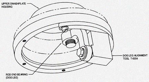
24 P/T T-0054 Swashplate Dog Leg Alignment Tool Dog Leg Alignment Tool Used to align dog legs during installation onto main rotor push-pull control rods. PS.CAT.0018.V10 23 June 18


25 P/T T Tail Rotor Grip Bearing Retention Nut Wrench Special Wrench for TR bearing retention nut Used for removal and installation of TR Grip bearings on spindle. Also used to torque tail rotor gearbox input shaft nut. T PS.CAT.0018.V10 24 June 18
26 T-0057 Damper Cycling Tool P/T Special Tool to Cycle Main Rotor Lead-Lag Dampers Used to cycle dampers to bleed air following maintenance. PS.CAT.0018.V10 25 June 18

27 P/T ASK4103-4DP Dog Leg Bearing Swaging Tools Tools for removing, & Installing ECD Bearings. See work aid PS.WAD.0024.V1 for use instructions. PS.CAT.0018.V10 26 June 18

28 P/T T-0086 Upper Guide Tube Retaining Nut Wrench Special Wrench for Upper Guide Tube Retention Nuts Used to remove and install nuts that secure the upper swashplate guide tubes into the upper swashplate housing. PS.CAT.0018.V10 27 June 18
29 T Tail Rotor Assy. Balance Tool P/T Static Balance Mandrel Used for static balancing the tail rotor assembly. PS.CAT.0018.V10 28 June 18

30 P/T T Swashplate Bushing Installation Tool Swashplate Assembly Tool Press tool for inserting DU bearings in swashplate. PS.CAT.0018.V10 29 June 18

31 P/T T Upper Swashplate Guide Tube Press Tools Press tools for Upper Guide Tube Removal Used to press upper guide tube assembly from upper swashplate assembly. PS.CAT.0018.V10 30 June 18

32 P/T T Swashplate DU Bushing Installation Tool Swashplate Bearing Installation Alignment Tool Used for aligning and installing DU bearings in swashplate assembly. PS.CAT.0018.V10 31 June 18
 Used to rig the correlator summing lever on the C")

33 T-0111-SET Correlator Rigging Tool P/T (C & F MODELS) TOOL NUMBER DISCRIPTION A/C APPLICABILITY T-0113 Correlator Rigging Tools P/T (C & F Models) Used to rig the correlator summing lever on the C and F series helicopters. T-0113 Throttle Stop Correlator Rigging Tool Used to set the throttle position while rigging the correlator on C and F models. T-0111-SET T-0111 T-0113 PS.CAT.0018.V10 32 June 18
34 T Tail Rotor Balance Stand P/T Tail Rotor Balance Stand Used as a balance fixture when static balancing tail rotors. PS.CAT.0018.V10 33 June 18

35 T Lower Swashplate Holding Fixture P/T Lower Swashplate Assembly Fixture Used to secure lower swashplate during assembly. PS.CAT.0018.V10 34 June 18

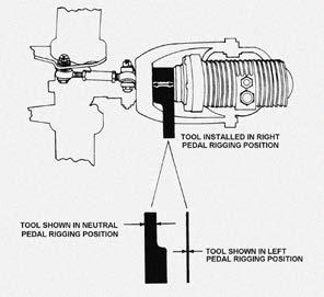
36 T-0140 Tail Rotor Rigging Tool T Used to hold the tail rotor pitch controls in the neutral position while adjusting cable tension. PS.CAT.0018.V10 35 June 18


37 T-0149 Grip Seal Installation Tool P/T Tool Kit for Installing Grip on Spindle Used to install the grip end seal on grips with TT straps, and Grip on Spindle. T PS.CAT.0018.V10 36 June 18

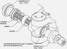
38 P/T T Main Rotor Flapping Bearing Installation Tool (Grease) Used for removing and installing main rotor flapping bearings in hubs that have grease lubricated flapping bearings. T is used if the hub has oil lubricated bearings. PS.CAT.0018.V10 37 June 18

39 P/T T-0152 Tail Rotor Balance Optical Sensor Fixture Attaches an Optical Sensor to the TRGB Attaches to Tail Rotor Gear Box and holds Velocimeter and optical sensor for balancing tail rotor assembly. PS.CAT.0018.V10 38 June 18
40 T Damper Piston / Seal Tool P/T Special Tool for Assembling MR Lead-Lag Dampers Used to compress the damper piston ring so that the piston can be assembled into the damper cylinder. PS.CAT.0018.V10 39 June 18
41 T U-Block Seal Installation Tool P/T Seal installation tool Used to press flapping seals into the universal block. PS.CAT.0018.V10 40 June 18
42 P/T T Main Rotor Flapping Bearing Installation Tool (oil) Flapping Bearing Removal and Installation Tool Used to press flapping bearings into and out of the universal blocks. PS.CAT.0018.V10 41 June 18

43 T Tail Rotor Blade Assy. Fixture P/T Holding fixture for TR Spindle Assembly Used to hold the tail Rotor assembly for assembly and disassembly. PS.CAT.0018.V10 42 June 18

44 T Main Rotor Hub Puller P/T Secures to the Main Rotor hub and pulls it from the transmission shaft. PS.CAT.0018.V10 43 June 18

45 T Main Rotor Blade Tip Targets P/T Used with a strobe light while tracking the helicopter. PS.CAT.0018.V10 44 June 18


46 T Socket & Adapter P/T Used to loosen mast nut. A m M T Socket & Adapter T Reaction Adapter 6202A Reaction bar TQ Multiplier Torque Multiplier assembly PS.CAT.0018.V10 45 June 18

47 T-0224 Rotor Hub Stand P/T Used to hold the assembled rotor hub when removed from the aircraft. PS.CAT.0018.V10 46 June 18

48 T-1575 Swashplate Centering Tool P/T Used to hold lower swashplate in centered position while rigging the controls. PS.CAT.0018.V10 47 June 18

49 T Blade Weight Removal Tool P/T Blade Plug Wrench Used to remove weight plugs from blade pockets. NOTE Ratchet NOT Included PS.CAT.0018.V10 48 June 18

50 T-1709 Upper Swashplate Bearing Tool P/T Used to support the upper swashplate bearing housing while removing and installing the bearing. PS.CAT.0018.V10 49 June 18

51 T-1758 Upper Swashplate Clamping Tool P/T Used to hold the upper swashplate assembly while performing maintenance. PS.CAT.0018.V10 50 June 18

52 T-1775 Cyclic Centering Rigging Tool P Cyclic Centering Rigging Tool. Used to hold the cyclic in the neutral position while rigging the cyclic controls. PS.CAT.0018.V10 51 June 18


53 T-2893 Tail Rotor Teeter Bearing Tool P/T Used to remove teeter bearings on tail rotor assembly. PS.CAT.0018.V10 52 June 18
54 T Damper Bleeding Tool Set P/T Bleeding tools for Hydraulic Main Rotor Dampers Special tools used to bleed air from hydraulic main rotor dampers. PS.CAT.0018.V10 53 June 18

55 T Cyclic Centering Tool T 480 Cyclic Centering Rigging Tool. Used to hold the cyclic in the neutral position while rigging the cyclic controls. PS.CAT.0018.V10 54 June 18
56 NPN Main Rotor Blade Balance Tool P/T Used to statically balance the main rotor blades. PS.CAT.0018.V10 55 June 18

57 NPN Digital Mast Nut Torque Multiplier P/T Used to torque the mast nut PS.CAT.0018.V10 56 June 18

58 Section-2 Drive Train and Powerplant TOOL NUMBER DISCRIPTION A/C APPLICABILITY T-0017 Transmission Hoist Eye P/T Main Rotor Transmission Shaft Support Tool Used to sling main transmission when the hub is not installed. PS.CAT.0018.V10 57 June 18
59 T-0029-SET Idler Pulley Installation Kit P Idler Pulley Bearing Installation Tools Used to support and align the idler pulley bearings while removing and installing bearings. PS.CAT.0018.V10 58 June 18

60 T-0044 Pulley Alignment Tool P Lower Pulley Alignment Tool Used to check and adjust alignment of upper and lower pulley in piston aircraft. PS.CAT.0018.V10 59 June 18

61 T TRGB Runout Tool P/T Tool for Measuring Runout on Tail Rotor Gearbox Output Shaft Used to measure runout on TRGB shaft with dial gauge. PS.CAT.0018.V10 60 June 18

62 P T-0078 Engine Oil Tube Adapter Installation Tool Engine Oil Filler Tube Adapter Special Wrench Used to install the oil filler tube adapter into the crankcase of the Lycoming engine. PS.CAT.0018.V10 61 June 18

63 P T-0088 Tail Rotor Drive Shaft Alignment Tool TOOL NUMBER DISCRIPTION A/C APPLICABILITY T T Used to align tail rotor drive shaft. Tail Rotor Drive Shaft Alignment Tool PS.CAT.0018.V10 62 June 18

64 T Taper Pin Removal Tool P/T Used to remove taper pins from TR drive shaft without damaging them. PS.CAT.0018.V10 63 June 18

65 T Upper Pulley Restraining Tool P Upper Pulley Restraining Tool Used to hold the upper pulley while installing the pinion nut on piston main rotor transmission. PS.CAT.0018.V10 64 June 18


66 T SET Pinion Nut Wrench P/T Special Wrench for Torqueing the Main Transmission Pinion Nut Used to Torque the Main Transmission Pinion Nut. NOTE Includes the T /4 Adapter. Order the T for Crowfoot only. TURBINE PISTON PS.CAT.0018.V10 65 June 18

67 T T Overrunning Clutch Housing Wrench 5/16 Special Wrench Used to removing and installing overrunning clutch support bearing hardware. PS.CAT.0018.V10 66 June 18


68 T Turbine Engine Hoist T Engine Winch Used to remove and install the Turbine engine. PS.CAT.0018.V10 67 June 18

69 T Belt Tension Tool T Belt Tensiometer Used to measure the drive belt tension. Calibrated Tool This must be sent back to Enstrom for calibration. PS.CAT.0018.V10 68 June 18

70 T-0141 Drive Pulley Alignment Tool T Pulley Alignment Tool Used to align the lower belt pulley. PS.CAT.0018.V10 69 June 18

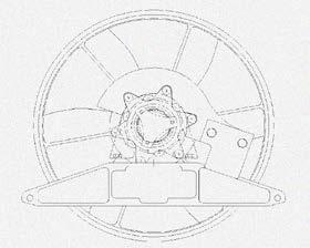
71 T Fan Balance Bracket P Optical Sensor Attach Tool for Balancing Fan on Piston Helicopters Attaches to pylon aft of fan and holds optical sensor to balance engine fan assembly. PS.CAT.0018.V10 70 June 18

72 T Turbine Engine Dolly T Turbine Engine Dolly Used to support engine while installing in helicopter. PS.CAT.0018.V10 71 June 18

73 T-0156 Oil Filler Tube Adapter Wrench P Turbine Engine Dolly Used to support engine while installing in helicopter. PS.CAT.0018.V10 72 June 18

74 T Upper Pulley Restraining Tool T Special Wrench to Hold Main Rotor Transmission Pinion Shaft Used to hold the upper pulley while removing or installing the pinion nut. PS.CAT.0018.V10 73 June 18

75 T T Oil Cooler Shaft Alignment Coupling Blower Short Shaft Alignment Tool Used for holding the short shaft while aligning the engine oil cooler blower assembly. PS.CAT.0018.V10 74 June 18


76 T Double Lip Seal Installation Tool T Double Lip Seal Installation Tool Used to install Rolls Royce Double Lip seal in engine gearbox. PS.CAT.0018.V10 75 June 18
77 T PLENUM BOX FOD COVERS T Used to protected lower plenum from FOD during maintenance. COVER COVER PS.CAT.0018.V10 76 June 18

78 T-0179 Magneto Spring Installation Tool P Used to insert springs in the magneto distributer block. PS.CAT.0018.V10 77 June 18
79 T C-20W Engine Stand T Rolls Royce Engine Support Stand Used to support engine while performing maintenance. PS.CAT.0018.V10 78 June 18


80 P/T T Overrunning Clutch Bearing Press Kit Clutch and Internal Drive Shaft Bearing Installation Kit Used to remove & install support bearings in the overrunning clutch and internal drive shaft assemblies. PS.CAT.0018.V10 79 June 18
81 T Turbine Fuel Nozzle Wrench T Special Wrench to Remove and Install Fuel Nozzle Used to remove and install fuel nozzle from engine while the engine is installed in the helicopter. PS.CAT.0018.V10 80 June 18
. This kit includes P/N T4131001-7 bore measurement assembly, a dial gauge assembly, clamp assembly, and articulating arm assembly. PS.CAT.0018.V10 81 June 18")
82 T Bore Concentricity Tool Set T (S/N 5131 & Subsequent) Measure the engine/gearbox assembly PTO shaft bores with tool kit T (Bore Concentricity Indicator Tool Set). This kit includes P/N T bore measurement assembly, a dial gauge assembly, clamp assembly, and articulating arm assembly. PS.CAT.0018.V10 81 June 18
83 T Mast Runout Tool P/T Tool to Measure Runout on Main Rotor Shaft Used to support dial gauge to measure main rotor gearbox shaft runout. PS.CAT.0018.V10 82 June 18
 Used to drain oil from the Main Rotor Gearbox. PS.CAT.0018.")
84 T MRGB Quick Drain P/T (Pistons with -9 MRGB & Higher. All Turbines) Used to drain oil from the Main Rotor Gearbox. PS.CAT.0018.V10 83 June 18
85 T-0204 Fan Shroud Alignment Tool P Used to hold the fan shroud in the proper position while the hardware is installed. The mechanic can reach through the holes in the tool to install the inside hardware. It needs to be about 3/16 inch larger in diameter then the fan PS.CAT.0018.V10 84 June 18
86 T-0213 MRGB Dolly P/T Main Rotor Gear Box Dolly Used to store and move main rotor transmissions. PS.CAT.0018.V10 85 June 18
87 T Fan Balancing Arbor P Used with T to statically balance the cooling fan. T Balance Arbor T PS.CAT.0018.V10 86 June 18
88 RBT18560 Double Lip Seal Puller T Double Lip Seal Puller Used to remove Double Lip seals from engine PTO bore. PS.CAT.0018.V10 87 June 18


89 Sec-3 Miscellaneous TOOL NUMBER DISCRIPTION A/C APPLICABILITY NPN Sprag Clutch Purge Tool P Used to purge sprag clutch assembly during servicing. Use a ¼-28 right angle zerk fitting. Unscrew the end and discard the check ball, and spring. Turn the clutch so that one plug-bolt is at the 12 o clock position and on is at either the 3 or 9 o clock position. Remove the top plug-bolt, and one of the side plug-bolts. Install the modified zerk fitting into the top hole. Using a suitable oil pump can, or syringe, push a sufficient amount of turbine engine oil into the clutch until the oil that runs out of the side hole appears clean. Replace the plug-bolt in the clutch assembly. PS.CAT.0018.V10 88 June 18


90 T-0035 Oleo Holding Tool P/T Special Wrench for Landing Gear Oleos. Used to hold the Seal Housing Assembly while disassembling the landing gear oleos. PS.CAT.0018.V10 89 June 18

91 T Oleo Disassembly Tool P/T Special Tool to Hold Landing Gear Oleo Assembly during disassembly, and assembly. PS.CAT.0018.V10 90 June 18

92 T TC Laser Alignment Emitter P/T Used to align the tailcone. The tailcone alignment device. It can only be used when the main rotor gear box is installed in the aircraft. PS.CAT.0018.V10 91 June 18

93 T TC Laser Alignment Target P/T Used with the T to align the tailcone. PS.CAT.0018.V10 92 June 18

94 T Turbine Fuel Probe Socket T Used for removing and installing the Ahlers fuel probe. PS.CAT.0018.V10 93 June 18
95 NPN Maintenance Stand P/T Used to work on, and around the aircraft. PS.CAT.0018.V10 94 June 18
96 T-3004 Tailcone Support Stand P/T Used to support the tailcone during Maintenance and or Weight and balance. PS.CAT.0018.V10 95 June 18
Illustrated Tool Catalog Piston & Turbine
 2018 Illustrated Tool Catalog Piston & Turbine PS.CAT.0018.V10 INTENTIONALLY LEFT BLANK 1 FROM: COMPANY: DATE: EMAIL: PO# BILL TO ADDRESS: SHIP TO ADDRESS: ARE 8130 TAGS REQUIRED? YES NO CONTACT NAME:
OR Clutch Housing Wrench Engine Hoist T-0141 Drive Pulley Alignment Tool
 Enstrom Illustrated Tool Catalog Piston & Turbine Rev 5, September, 2016 T-0003 Lead Lag Nut Wrench T-0005 Damper Rod End Removal Tool T-0009 Main Rotor Blade Bolt guide Bullet T-0011 Main Rotor Hoist
CHAPTER 36 SPECIAL TOOLS Special Tools Illustrations and Tasks
 CHAPTER 36 SPECIAL TOOLS Section Title 36-10 Special Tools............................................. 36.1 36-20 Illustrations and Tasks....................................... 36.2 Page OCT 2018 Chapter
G-LAIN - Recurring Maintenance (All)
") MRB Daily inspection AD X Perform Annual inspection as per RHC R22 MM 2.400 and Lycoming OM, and CAA/LAMP/H/2007 Issue 1, First Aid Kit i.a.w. CAA/LAMP/H/2007, Issue 1, 12 MO 22-11-2016 22-11-2017 0 X
MRB Daily inspection AD X Perform Annual inspection as per RHC R22 MM 2.400 and Lycoming OM, and CAA/LAMP/H/2007 Issue 1, First Aid Kit i.a.w. CAA/LAMP/H/2007, Issue 1, 12 MO 22-11-2016 22-11-2017 0 X
Tribal Knowledge, converting an Enstrom Piston helicopter from Lamiflex bearings to TT straps
 Tribal Knowledge, converting an Enstrom Piston helicopter from Lamiflex bearings to TT straps The Airwolf kit comes with all parts necessary for assembly and is pre-packaged in shock proof packaging. 1
AIRWOLF AEROSPACE LLC
 AIRWOLF AEROSPACE LLC 15369 Madison Rd. Middlefield, OH 44062-8404 U.S.A. (440) 632-1687 / (440) 632-1685 Fax www.airwolfaeospace.com / info@airwolfaerospace.com Installation Instructions For The Installation
Tailcone Alignment Work aid, Using T (Laser Fixture), T (Target)
, T (Target)") Tailcone Alignment Work aid, Using T-0199-1 (Laser Fixture), T-0200-5 (Target) Required special tools: T-0199-1 T-0200-5 References: 1. Turbine: Maintenance Manual, Page: 8-75, 8-76, 8-77. IPC page: 3-2,
Tailcone Alignment Work aid, Using T-0199-1 (Laser Fixture), T-0200-5 (Target) Required special tools: T-0199-1 T-0200-5 References: 1. Turbine: Maintenance Manual, Page: 8-75, 8-76, 8-77. IPC page: 3-2,
CHAPTER 63 MAIN ROTOR DRIVE SYSTEM
 Section Title CHAPTER 63 MAIN ROTOR DRIVE SYSTEM 63-00 Description............................................... 63.1 63-10 Engine Shaft Weldment...................................... 63.1 63-11 (Engine
SERVICE INFORMATION LETTER # 0121 Addition A. Subject; Tracking the Enstrom Rotor System using the Chadwick 2000 balance system.
 SERVICE INFORMATION LETTER # 0121 Addition A Date: Subject; Tracking the Enstrom Rotor System using the Chadwick 2000 balance system. Models: All models Effectively: All Serial Numbers Experience shows
CHAPTER 29 HYDRAULICS Description Hydraulic Pump Hydraulic Reservoir Hydraulic Servos
 Section Title CHAPTER 29 HYDRAULICS 29-00 Description............................................... 29.1 29-10 Hydraulic Pump............................................ 29.1 29-20 Hydraulic Reservoir.........................................
1. SUBJECT: : New Improved Tail Rotor Teeter Bearing Assembly. 2. MODELS: F28C, 280C, F28F, 280F, 280FX, TH-28 and 480 Helicopters
 SERVICE INFORMATION LETTER NO. 0141 Page 1 of 5 DATE: September 11, 1995 1. SUBJECT: : New Improved Tail Rotor Teeter Bearing Assembly 2. MODELS: F28C, 280C, F28F, 280F, 280FX, TH-28 and 480 Helicopters
TRACKING BLADES WITH THE ENSTROM ROTOR SYSTEM ENSTROM TH-28/480 SERIES MAINTENANCE TRAINING
 TRACKING BLADES WITH THE ENSTROM ROTOR SYSTEM 1 Experience tells us that some of the earlier published information on how to track the Rotor system isn t really optimum. This procedure should be used anytime
SAFARI Helicopter Flight Control Rigging Manual Revision 9 4/3/2010 CHR International Inc.
 SAFARI Helicopter Flight Control Rigging Manual Revision 9 4/3/2010 CHR International Inc. The following procedures are meant as a guide to assist you in the safe configuration of your helicopter s Flight
CHAPTER 65 TAIL ROTOR DRIVE SYSTEM. Section Title Page
 CHAPTER 65 TAIL ROTOR DRIVE SYSTEM Section Title Page 65-00 Description........................................ 65.1 65-10 Tail Rotor Drive Fan Shaft.............................. 65.1 65-20 Tail Rotor
C-GQNS Detailed View. GQNS Date Oct 26, Registration C- Make Bell TTAF Serial No.
 Quantum Helicopters Ltd., 4445 Bristol Road, Terrace, B.C. CANADA V8G 0E9 Ph. Office: (250) 615-0145 Fax:(250) 635-0147 qhl@quantumhelicopters.ca Detailed View Registration C- GQNS Date Oct 26, 2010 Make
BACKGROUND: To provide information relating to the TT strap installation installed in the piston helicopters under Airwolf STC SH03465CH.
 BACKGROUND: To provide information relating to the TT strap installation installed in the piston helicopters under Airwolf STC SH03465CH. Enstrom helicopters delivered new from the factory starting in
Page 1 of HP B&S Vanguard Engine
 1405 Page 1 of 41 14 HP B&S Vanguard Engine 1405 Page 2 of 41 14 HP B&S Vanguard Engine Ref # Part Number Qty S/P/F Description BS-28Q777-0647-E1 1 14 HP B&S Vanguard Engine 1 BS-496412 1 Cylinder Assembly
PARTS MANUAL. Time Saver Wide Cut Mower. I N E CUB G E N U
 PARTS MANUAL Time Saver Wide Cut Mower G E N U FAC TORY I N E PARTS 1-800-965-4CUB www.cubcadet.com FORM NO. 69-03049 PRINTED IN U.S.A. CUB CADET LLC, P.O. BOX 361131 CLEVELAND, OHIO 44136-0019 1/29/200
ROBINSON MODEL R-44 HELICOPTER TRACK AND BALANCE
 Application Note AN-MV2-R44 Rev 02-10 May 2012 MicroVib II Aircraft Analyzer Helicopter Track and Balance ROBINSON MODEL R-44 HELICOPTER TRACK AND BALANCE Dynamic Solutions Systems, Inc. (760) 598-4000
CHAPTER 22 SERVICING
 CHAPTER 22 SERVICING Section Title 22-10 Main Rotor Gearbox......................................... 22.1 22-11 Cleaning Chip Detector..................................... 22.3 22-12 Cleaning Sight Gage.......................................
All low rate dampers are functionally the same but should not be used in mixed sets
 SERVICE INFORMATION LETTER 0075A Supercedes Service Information Letter 0075 Page 1 of 9 Date: November 20, 1980 Subject: Model: Effectivity: Main Rotor Blade Damper F-28A, F-28C, 280, 280C Not Applicable
2006 Edition For training purposes only
 Piston Helicopter Pilot Training Guide 2006 Edition For training purposes only Enstrom Helicopter Corporation 1 Table of Contents Introduction Aircraft Description Aircraft servicing Aircraft Systems Electrical
CHAPTER 9 GROUND HANDLING. Section Title Page
 CHAPTER 9 GROUND HANDLING Section Title Page 9-10 Ground Handling.................................... 9.1 9-11 Ground Handling Wheels...................... 9.1 9-12 Moving Helicopter on Ground Handling
ALERT SERVICE BULLETIN INDEX
 ALERT SERVICE BULLETIN INDEX NOTE THIS INDEX IS A LIST OF ALERT SERVICE BULLETINS ISSUED. THIS INDEX DOES NOT IDENTIFY WHICH ALERT BULLETINS ARE ACTIVE OR INACTIVE. THE. COLUMN INDICATES THE MAINTENANCE
CHAPTER 12 SERVICING. Section Title Page
 CHAPTER 12 SERVICING Section Title Page 12-10 Main Rotor Gearbox.................................. 12.1 12-11 Servicing................................. 12.1 12-12 Filter Replacement...........................
FAA APPROVED PARTS FOR YOUR MD500
 Vertical Stabilizer D, E, F AM369D23600-503 OEM 369D23600-503 Horizontal Stabilizer D: 369X23601-511 OEM 369D23601-511 E: 421X-087-905 OEM 421-087-905 F: 421X-087-903 OEM 421-087-903 Tailboom D, E, F 369X23500-505
DEPARTMENT OF TRANSPORTATION FEDERAL AVIATION ADMINISTRATION TYPE CERTIFICATE DATA SHEET NO. 4H12
 DEPARTMENT OF TRANSPORTATION FEDERAL AVIATION ADMINISTRATION 4H12 Revision 30 Sikorsky 269A 269A-1 269B,269C 269C-1, 269D September 26, 2011 TYPE CERTIFICATE DATA SHEET NO. 4H12 This data sheet, which
71253, XL 440H Lawn Tractor, 2008 (SN ) : BLOWER HOUSING ASSEMBLY BRIGGS AND STRATTON MODEL 31P E1 [1/
 : BLOWER HOUSING ASSEMBLY BRIGGS AND STRATTON MODEL 31P E1 [1/") 71253, XL 440H Lawn Tractor, 2008 (SN 280000001-280999999) : BLOWER HOUSING ASSEMBLY BRIGGS AND STRATTON MODEL 31P777-0133-E1 [1/ Page 1 of 50 71253, XL 440H Lawn Tractor, 2008 (SN 280000001-280999999)
71253, XL 440H Lawn Tractor, 2008 (SN 280000001-280999999) : BLOWER HOUSING ASSEMBLY BRIGGS AND STRATTON MODEL 31P777-0133-E1 [1/ Page 1 of 50 71253, XL 440H Lawn Tractor, 2008 (SN 280000001-280999999)
Rolls-Royce Corporation M250-C20R COMMERCIAL ENGINE BULLETIN (CEB) Technical Publications Index
 Technical Publications Index") Rolls-Royce Corporation M250-C20R COMMERCIAL ENGINE BULLETIN (CEB) Technical Publications Index January 2, 2018 72-4001 Engine Conversion, 250 -C20R/2 to 250 -C20R/1 72-4002 Prior To Publication 72-4003
Rolls-Royce Corporation M250-C20R COMMERCIAL ENGINE BULLETIN (CEB) Technical Publications Index January 2, 2018 72-4001 Engine Conversion, 250 -C20R/2 to 250 -C20R/1 72-4002 Prior To Publication 72-4003
Cycles values Cycle Name Value Cycle Name Value Cycle Name Value Cycle Name Value
 Ph. Office: Fax: Mar 23, 2012 Detailed View Registration Date Mar 23, 2012 Make Bell TTAF 22151.3 Model B Serial 30297 Actions Cal - Calibration Cha - Change Ins - Inspection On - On Condition Ove - Overhaul
HelicopterBuyer, Inc AgustaBell 412 HP S/N: 25802, R/N: D-HHAA. 8,450 hours Total Time. Maintenance Tracking Summary
 Main Rotor Blades Part Number Type Interval T/R % T/R Main Rotor Hub Part Number Type Interval T/R % T/R M/R Hub Assembly 412-010-100-181 IN 2,500 1,242 50% Mast Cap Retention Assy 412-010-171-103 LL 10,000
CHAPTER 18 WEIGHT AND BALANCE
 CHAPTER 18 WEIGHT AND BALANCE Section Title 18-10 Leveling................................................. 18.1 18-11 Leveling at Lower Right Side Frame Tube & Aft Landing Gear Cross Tube.. 18.1 18-12
Enstrom Helicopter Corporation 1 Post Office Box 490 Menominee, Michigan U.S.A. Phone (906)
") Pilot Training Guide March 10, 2008 2008 Edition 2 For training purposes only Enstrom Helicopter Corporation 1 Table of Contents Introduction 3 Aircraft Description & Construction Details 4 Aircraft servicing
Pilot Training Guide March 10, 2008 2008 Edition 2 For training purposes only Enstrom Helicopter Corporation 1 Table of Contents Introduction 3 Aircraft Description & Construction Details 4 Aircraft servicing
RIGGING THE FLIGHT CONTROLS
 RIGGING THE FLIGHT CONTROLS Rigging refers to the installation and adjustment of the rods that move flight surfaces in response to inputs from the controls of the helicopter. These rods are cut to length,
HELIWORK SERVICES UK APPROVED CAPABILITY MANUAL. Ref: HW/ENG/145/3. Issue 6
 HELIWORK SERVICES Ref: HW/ENG/145/3 Issue 6 Dated: 16 October 2013 General INTRODUCTION Section: 0.1 Issue: 6 Rev: 1 Date: 01/06/2016 This Approved Capability Manual Ref HW/ENG/145/3 contains a detailed
CHAPTER 1 GENERAL. Section Title
 Section Title CHAPTER 1 GENERAL 1-00 Introduction.............................................. 1.1 1-10 R66 Maintenance Manual Revisions.............................. 1.1 1-20 R66 Maintenance Authorization.................................
TECHNICAL MANUAL. Approved for public released; distribution is unlimited. I. This copy is a reprint which includes current pages from Change 1 and 2.
 TM 55-1520-210-23P-3 TECHNICAL MANUAL AVIATION UNIT AND INTERMEDIATE MAINTENANCE REPAIR PARTS AND SPECIAL TOOLS LIST (INCLUDING DEPOT MAINTENANCE REPAIR PARTS AND SPECIAL TOOLS) FOR HELICOPTER, UTILITY
CYLINDER HEAD. Ref. Part No. Number Description Qty Remarks
 A1 A2 A3 A4 CYLINDER HEAD 1 3FA-11110-01-00 CYLINDER HEAD ASSY...... 1 2 90116-06541-00. BOLT, STUD............. 2 3 22F-11134-10-00. GUIDE, EXHAUST VALVE... 2 4 93440-10109-00. CIRCLIP.................
CHAPTER 21 ENVIRONMENT CONTROL. Section Title Page
 CHAPTER 21 ENVIRONMENT CONTROL Section Title Page 21-00 Description........................................ 21.1 21-10 Ventilation........................................ 21.3 21-11 Nose Vent................................
REMOVAL AND INSTALLATION
 303-03-1 Engine Cooling 303-03-1 REMOVAL AND INSTALLATION Radiator, Cooling Fan and Shroud Special Tool(s) Wrench, Fan Clutch Nut 303-240 (T84T-6312-D) Holding Wrench, Fan Pulley 303-239 (T84T-6312-C)
Kysor On/Off Rear Air Fan Drive
 . Proper precautions must be taken to prevent personal injury from contact with moving parts, unintended engine start or other hazards present when working with powered equipment. Refer to the vehicle
Small Engine Parts. Super 2 Chain Saw UT Page 1 of 12 Engine Internals
 Small Engine Parts Super 2 Chain Saw UT-10654 Page 1 of 12 Engine Internals Super 2 Chain Saw UT-10654 Page 2 of 12 Engine Internals Ref # Part Number Qty Description 1 A95072 1 CRANKCASE & CYLINDER ASSY.
Bearing and Seal Installation Tool T1 Clutch Assembly Stand X X X X Shift Handle Tool X X T Bearing Cup Driver X X
 Bravo Sterndrive Bravo Sterndrive Tool Application Chart Part No. Description Bravo One Bravo Two Bravo Three Blackhawk 11 24156 Hex Nut 12 34961 Washer 91 12427 Shift Cable Adjustment Tool 91 17256 Bearing
XL Chain Saw UT Page 1 of 12 Engine Internals
 XL Chain Saw UT-10655 Page 1 of 12 Engine Internals XL Chain Saw UT-10655 Page 2 of 12 Engine Internals Ref # Part Number Qty S/P/F Description 1 A95071A 1 CRANKCASE & CYLINDER ASSY. 2 80571 3 /P SCREW-
Kysor On/Off Rear Air Fan Drive
 . Proper precautions must be taken to prevent personal injury from contact with moving parts, unintended engine start, or other hazards present when working with powered equipment. Refer to the vehicle
FAA-Approved Parts Price List
 FAA-Approved Parts Price List Downloaded From Website: Sun, Feb 4, 2018 MDHI P/N Name Aerometals P/N Price 369A1003-501 Scissors Link 369X1003-501 $550.00 369A1004-5 Folding Pin 369X1004-5 $445.00 369A1005-3
Z-Force 60 KW 53AA5DBJ Page 1 of 57 Air Filter & Muffler
 Z-Force 60 KW 53AA5DBJ Page 1 of 57 Air Filter & Muffler Z-Force 60 KW 53AA5DBJ Page 2 of 57 Air Filter & Muffler Ref # Part Number Qty S/P/F Description 11011 KM-11011-7003 1 S CASE-AIR FILTER 11013 KM-11013-7009
1. SUBJECT: F-28A and 280 Left Side Tail Rotor Installation
 Page 1 of 16 DATE: January 31, 2005 1. SUBJECT: F-28A and 280 Left Side Tail Rotor Installation 2. MODEL: F-28A and 280 3. EFFECTIVITY: All serial numbers 4. BACKGROUND: The left side installation of the
480B Technical Specifications
 480B Technical Specifications 1. Design History The Enstrom 480B is a single engine, turbine powered helicopter derived from the Enstrom F28 family of helicopters. The original piston powered F28 received
Seabee Annual Inspection Procedures
 Procedures Due to the wide variety of Seabee s flying out there, these procedures should be modified to fit YOUR Seabee. Make sure that all AD s are complied with as well as any required Service Bulletins
Section 13. Tail Rotor Drive. RotorWay International A600 TALON Construction Manual. Section 13. Page A
 RotorWay International Page A Tail Rotor Drive Procedures covered in this section: Install driveshafts and gearboxes; install drive belt and tensioner; fabricate and install tail rotor pitch actuator arms;
ATV I l. l u. r a. Parts Manual ARCTIC CAT. 250 cc/300 cc
 2000 I l l u st ATV 250 cc/300 cc Model No. A2000ATE2AUSG (250 - Green) Model No. A2000ATE2AUSR (250 - Red) Model No. A2000ATF2AUSG (300 2x4 - Green) Model No. A2000ATF2AUSR (300 2x4 - Red) Model No. A2000ATF4AUSG
TRANSMISSION 6.7 GENERAL HOME. See Figure The transmission is a five-speed constantmesh type housed in an extension of the crankcase.
 TRANSMISSION 6.7 GENERAL See Figure 6-46. The transmission is a five-speed constantmesh type housed in an extension of the crankcase. b06x6x Neutral st Gear Mainshaft Mainshaft 4 5 4 5 Countershaft Out
Illustrated Parts List Vanguard to Compliance
 Non-Compliance Illustrated Parts List Vanguard Model Series 104700 to 104799 FORM MS-9878 7/93 REPLACES FORM MS-9878 5/92 FILE IN SECT. 2 OF SERVICE MANUAL 104700 to 104799 Compliance TYPE NUMBERS 0101,
Parts Manual. RZT SERIES TRACTOR Model Number RZT 42 w/42" Mower Deck. CUB CADET LLC P.O. BOX CLEVELAND, OHIO [www.cubcadet.
 Parts Manual RZT SERIES TRACTOR Model Number RZT w/" Mower Deck CUB CADET LLC P.O. BOX CLEVELAND, OHIO -00 [www.cubcadet.com] PRINTED IN U.S.A. FORM NO. -0D (/0) -- MODEL RZT TABLE OF CONTENTS DESCRIPTION
CHAPTER 10 RIGGING, TRACK AND BALANCE
 CHAPTER 1 RIGGING, TRACK AND BALANCE Section Title Page 1. Rigging, Track and Balance................................... 1.1 1.1 Introduction........................................... 1.1 1.2 Rod End
Illustrated Parts List to 90199
 Illustrated Parts List Model Series 90100 to 90199 TYPE NUMBERS 0004, 0005, 0007, 0015, 0016, 0022, 0104, 0114, 0116, 0117, 0119, 0120, 0122, 0123, 0124, 0125, 0126, 0127, 0129, 0130, 0131, 0132, 0134.
19-52ZX TimeCutter Riding Mower
 Form Number 3350-173 Rev C 19-52ZX TimeCutter Riding Mower ZX Model No. 74802-240000001 and up. Parts Catalog Ordering Replacement Parts To order replacement parts, please supply the part number, the quantity,
SPARE PARTS LIST. CHAIN SAWS 365SP from
 SPARE PARTS LIST CHAIN SAWS 365SP from 2018-01- CHAIN BRAKE & CLUTCH COVER 365SP from 2018-01- CHAIN BRAKE & CLUTCH COVER 365SP from 2018-01- Ref Part No Description Remark QTY KIT 1 525 75 52-01 SCREW
ASB AC. HTC,Part number (P/N) 500P and -103, or MDHI P/N 369D , -503, and -505
 500P and -103, or MDHI P/N 369D , -503, and -505") MANDATORY SERVICE BULLETINES "ASB" N650AG 369HM HUGHES "500C" PAGE 1 of 1 Bi-We SB AD ACTION PART REC F. DUE QAT 2016-05-09 AM SB-1103 2016-04-15 ONE -TIME INSPECTION OF FUEL PUMP HARNESS ROUTING AND DECAL
MANDATORY SERVICE BULLETINES "ASB" N650AG 369HM HUGHES "500C" PAGE 1 of 1 Bi-We SB AD ACTION PART REC F. DUE QAT 2016-05-09 AM SB-1103 2016-04-15 ONE -TIME INSPECTION OF FUEL PUMP HARNESS ROUTING AND DECAL
14A6816H190 GT-2150 (2003) Page 1 of 28 Carburetor
 Page 1 of 28 Carburetor") 14A6816H190 GT-2150 (2003) Page 1 of 28 Carburetor 14A6816H190 GT-2150 (2003) Page 2 of 28 Carburetor TC-640221 1 /P Carburetor (Incl 184 of Engine Parts Lists) 1 TC-640216 1 Throttle Shaft & Lever Assembly
14A6816H190 GT-2150 (2003) Page 1 of 28 Carburetor 14A6816H190 GT-2150 (2003) Page 2 of 28 Carburetor TC-640221 1 /P Carburetor (Incl 184 of Engine Parts Lists) 1 TC-640216 1 Throttle Shaft & Lever Assembly
SUSPENSION - FRONT Toyota Celica DESCRIPTION ADJUSTMENTS & INSPECTION WHEEL ALIGNMENT SPECIFICATIONS & PROCEDURES WHEEL BEARING
 SUSPENSION - FRONT 1988 Toyota Celica FRONT SUSPENSION Toyota DESCRIPTION Vehicles are equipped with front wheel drive and independent MacPherson strut front suspension. Suspension consists of vertically
SERVICE INFORMATION LETTER
 SERVICE INFORMATION LETTER DATE: August 19, 2015 SERVICE INFORMATION LETTER NO. 0183 Page 1 of 18 1. SUBJECT: Collective Stick Socket Replacement 2. MODEL: F28A, 280, F28C, 280C, F28F, 280F, and 280FX
TimeCutter SS 4200 Riding Mower
 Form No. 3409-413 Rev A TimeCutter SS 4200 Riding Mower Model No. 74720 Serial No. 400000000 and Up Register at www.toro.com. Original Instructions (EN) *3409-413* A Ordering Replacement Parts To order
CHAPTER 64 TAIL ROTOR. Section Title Page
 CHAPTER 64 TAIL ROTOR Section Title Page 64-00 Description........................................ 64.1 64-10 Tail Rotor Assembly.................................. 64.1 64-11 Static Balance..............................
TRANSMISSION 6.7 GENERAL HOME. See Figure The transmission is a five-speed constantmesh type housed in an extension of the crankcase.
 TRANSMISSION 6.7 GENERAL See Figure 6-45. The transmission is a five-speed constantmesh type housed in an extension of the crankcase. Mainshaft Neutral Mainshaft st Gear b06x6x Countershaft 4 Out 5 Countershaft
90 Utility Model Number A2013KUB2BUSZ SHARE OUR PASSION.
 2013 90 Utility Model Number A2013KUB2BUSZ TM SHARE OUR PASSION. TABLE OF CONTENTS 2013 ATV 90 (Model No. A2013KUB2BUSZ) BODY PANEL AND HEADLIGHT ASSEMBLY... 1 FRONT AND REAR RACK ASSEMBLY... 2 FRAME AND
SECTION 4 NORMAL PROCEDURES CONTENTS
 CONTENTS Page Recommended Airspeeds....................... 4-1 Daily or Preflight Checks........................ 4-1 Before Starting Engine.......................... 4-6 Starting Engine and Run-Up......................
SPARE PARTS LIST. CHAIN SAWS 365 X-TORQ from
 SPARE PARTS LIST CHAIN SAWS 365 X-TORQ from 2017-11 - ACCESSORIES 365 X-TORQ from 2017-11 - ACCESSORIES 365 X-TORQ from 2017-11 - Ref Part No Description Remark QTY KIT 1 588 79 74-01 TOOL 1 2 501 69 17-01
TimeCutter SS 4225 Riding Mower
 Form No. 3417-390 Rev D TimeCutter SS 4225 Riding Mower Model No. 74726 Serial No. 400000000 and Up Register at www.toro.com. Original Instructions (EN) *3417-390* D Ordering Replacement Parts To order
CHAPTER 4 AIRWORTHINESS LIMITATIONS
 Section Title CHAPTER 4 AIRWORTHINESS LIMITATIONS 4-10 Airworthiness Limitations..................................... 4.1 4-20 Additional Limitations....................................... 4.3 4-21 Parts
Mfg. No: 12S F8
 Parts Manual Mfg. No: 12S452-0049-F8 Copyright Briggs and Stratton. All Rights reserved 03-Oct-2017 Model Components Table Of Contents Page Air Cleaner, Exhaust System...........................................................................
STX-26 Stump Grinder
 Form No. 3365-311 Rev B STX-26 Stump Grinder Model No. 23210 Serial No. 310000001 and Up Model No. 23210G Serial No. 310000001 and Up Register at www.toro.com. Original Instructions (EN) *3365-311* B Ordering
STX-26 Stump Grinder
 Form No. 3383-656 Rev B STX-26 Stump Grinder Model No. 23208 Serial No. 314000001 and Up Model No. 23208G Serial No. 314000001 and Up Register at www.toro.com. Original Instructions (EN) *3383-656* B Ordering
S/N 1H019H - 1H310H Page 1 of 33 46" Cutting Deck Assembly
 1180 S/N 1H019H - 1H310H Page 1 of 33 46" Cutting Deck Assembly 1180 S/N 1H019H - 1H310H Page 2 of 33 46" Cutting Deck Assembly 1 17982 1 S Reinforcement Spindle Plate 2 618-0430 1 S Spindle Assembly w/
2002 F-Super Duty /Excursion Workshop Manual
 Page 1 of 25 SECTION 307-01: Automatic Transaxle/Transmission 2002 F-Super Duty 250-550/Excursion Workshop Manual ASSEMBLY Procedure revision date: 05/23/2001 Transmission Special Tool(s) Remover, O-Ring
Kysor Rear Air Fan Drives
 On/Off Technology for Heavy-Duty Truck Applications Installation & Service Guide Kysor Rear Air Fan Drives thermal.borgwarner.com For Additional BorgWarner Thermal Systems Information: 800-927-7811 USA
2001 Dodge Dakota ENGINES 4.7L V8
 FRONT COVER Removal & Installation 1. Disconnect negative battery cable. Remove drive belt. Remove A/C compressor mounting bolts, and position compressor aside. Drain cooling system. Remove radiator hoses.
CHAPTER 63 MAIN ROTOR DRIVE SYSTEM. Figure Title Page 63-1 Main Rotor Gearbox and Mast Assembly Main Rotor Gearbox Installation
 CHAPTER 63 MAIN ROTOR DRIVE SYSTEM Figure Title Page 63-1 Main Rotor Gearbox and Mast Assembly...................... 63.0 63-5 Main Rotor Gearbox Installation............................. 63.4 63-7 Rotor
1983 BMW 320i. 1.8L 4-CYL 1983 Engines - 1.8L 4-Cylinder Engines - 1.8L 4-Cylinder
 ENGINE IDENTIFICATION 1.8L 4-CYL 1983 Engines - 1.8L 4-Cylinder For engine repair procedures not covered in this article, see ENGINE OVERHAUL PROCEDURES - GENERAL INFORMATION article in the GENERAL INFORMATION
DVX 90 MODEL NUMBER A2008KSB2BUSD (BLACK-RED) MODEL NUMBER A2008KSB2BUSE (BLACK-CAT GREEN) MORE TO GO ON. TM
 MODEL NUMBER A2008KSB2BUSE (BLACK-CAT GREEN) MORE TO GO ON. TM") 2008 DVX 90 Illustrated Parts Manual MODEL NUMBER A2008KSB2BUSD (BLACK-RED) MODEL NUMBER A2008KSB2BUSE (BLACK-CAT GREEN) MORE TO GO ON. TM TABLE OF CONTENTS Black-Red (Model No. A2008KSB2BUSD) Black-Cat
2008 DVX 90 Illustrated Parts Manual MODEL NUMBER A2008KSB2BUSD (BLACK-RED) MODEL NUMBER A2008KSB2BUSE (BLACK-CAT GREEN) MORE TO GO ON. TM TABLE OF CONTENTS Black-Red (Model No. A2008KSB2BUSD) Black-Cat
ENGINE, WITH CONTAINER: TURBOSUPERCHARGED, DIESEL, FUEL INJECTION, 90-DEGREE V TYPE, AIR-COOLED, 12-CYLINDER, ASSEMBLY;
 *TM 9-2815-200-35 DEPARTMENT OF THE ARMY TECHNICAL MANUAL DIRECT SUPPORT, GENERAL SUPPORT AND DEPOT MAINTENANCE MANUAL INCLUDING REPAIR PARTS AND SPECIAL TOOLS LISTS FOR ENGINE, WITH CONTAINER: TURBOSUPERCHARGED,
Illustrated Parts List to
 TYPE NUMBERS 0022 through 0035, 0040 through 0062, 0070, 0076,0100, 0102, 0120 through 0125, 0307, 0318,0320, 0326, 0340 through 0366, 0370 through 0378, 0382, 0385, 0390, 0391, 0394, 0398, 0402, Illustrated
CHAPTER 6 POWERPLANT
 Section Title CHAPTER 6 POWERPLANT 6.000 Powerplant And Related Systems................................ 6.1 6.001 Introduction............................................ 6.1 6.002 Description.............................................
Airbus Helicopters Canada MAINTENANCE REPAIR & OVERHAUL SERVICES
 Airbus Helicopters Canada MAINTENANCE REPAIR & OVERHAUL SERVICES Airbus Helicopters Canada prides itself on its comprehensive support and services solutions. In addition to being certified for overhauls
CHAPTER 3 LIFE-LIMITED COMPONENTS
 CHAPTER 3 LIFE-LIMITED COMPONENTS Section Title 3.100 Life-Limited Components..................................... 3.1 3.110 Time-in-Service Records................................... 3.1 3.120 Fatigue
Mfg. No: E1
 Parts Manual Mfg. No: 120312-0143-E1 Copyright Briggs and Stratton. All Rights reserved 05-Jan-2018 Model Components Table Of Contents Page Air Cleaner, Exhaust System...........................................................................
PARTS CATALOG ODYSSEY INCLUDES MOWER
 PARTS CATALOG 8-3350 ODYSSEY INCLUDES MOWER INDEX PAINT ENGINES GENERAL INFO PRODUCT IDENTIFICATION NUMBERS (P.I.N.) OR SERIAL NUMBERS (S/N) ENGINE MODEL, SERIAL AND SPECIFICATION NUMBERS TRACTOR MODEL
CYLINDER HEAD. Ref. Part No. Number Description Qty Remarks
 A1 A2 A3 A4 CYLINDER HEAD 1 1UY-11110-02-00 CYLINDER HEAD ASSY...... 1 2 3Y1-11133-11-00. GUIDE, INTAKE VALVE..... 2 3 93440-12052-00. CIRCLIP................. 2 4 90401-06001-00. BOLT, UNION............
Illustrated Parts List to
 Illustrated Parts List Model Series TYPE NUMBERS 0027, 0031, 0117, 0118, 0130, 0131, 0133 through 0137. FORM MS 8696 6/98 REPLACES FORM MS 8696 10/97 FILE IN SECT. 2 OF SERVICE MANUAL TO FIND THE CORRECT
CHAPTER 13 INSTRUMENTS
 CHAPTER 13 INSTRUMENTS Section Title Page 13.000 Description.............................................. 13.1 13.100 Pitot-Static System......................................... 13.3 13.200 Primary Instruments........................................
PARTSBOOK. Hall Manufacturing, Inc E. Washington Ave., P.O. Box Drawer 5638 North Little Rock, AR (501)
") 540 RPM 2 PARTSBOOK This part of the manual contains part numbers and illustrations based on the latest information available at the time of print. Hall Manufacturing, Inc. reserves the right to make changes
540 RPM 2 PARTSBOOK This part of the manual contains part numbers and illustrations based on the latest information available at the time of print. Hall Manufacturing, Inc. reserves the right to make changes
Illustrated Parts List 31F700
 FORM MS 5035 09/08/2004 REPLACES FORM MS 5035 08/04/2004 FILE IN SECT. 2 OF SERVICE MANUAL Illustrated Parts List Model Series TYPE NUMBERS 0110 through 0318. TABLE OF CONTENTS Air Cleaner.........................
CHAPTER 3 LIFE-LIMITED COMPONENTS
 Section Title CHAPTER 3 LIFE-LIMITED COMPONENTS 3.000 Life-Limited Components...................................... 3.1 3.001 Introduction............................................. 3.1 3.002 Time-In-Service
CREATIVE EQUIPMENT CC 18 Main Road, Fishers Hill, Germiston, 1401 Tel: Fax:
 FRAME & DRIVE IDLER ASSEMBLY REF # PART # DESCRIPTION 1 MTD603-04680A FRAME ASSY 2 MTD703-05829 DRIVE IDLER ARM 3 MTD710-0520 HEX SCREW, 3/8-16 x 1.5 4 MTD710-3005 HEX SCREW, 3/8-16 x 1.25 5 MTD712-04065
480T All-Wheel-Steer. Loader
 480T All-Wheel-Steer Form No. 918119 Revision C Loader Beginning Serial Number: 342100107 PARTS MANUAL Introduction When ordering service parts, specify the correct part number, full description, quantity
Cycles values. Cycle Name Value Cycle Name Value Cycle Name Value Cycle Name Value. Components. Tracking No.
 Jun 27, 2016 E & B Helicopters Ltd Box 1000 2595 Island Highway Campbell River, BC V9W 6Y4 Canada Ph. Office: 250-287-4421 Fax:250-287-4352 info@ebhelicopters.com Detailed View Registration Date Jun 27,
Illustrated Parts List
 FORM MS 0670 3C 8/2001 REPLACES FORM MS 0670 2Q 11/2000 FILE IN SECT. 2 OF SERVICE MANUAL Illustrated Parts List Model Series TYPE NUMBERS 0042 through 1256. For Use On Engines Built Before Date Code 01070100.
Service Tools. Service and Repair Manual Model 900/950/990 ITEM PART NO. DESCRIPTION ITEM PART NO. DESCRIPTION ITEM PART NO.
 12 1 3 2 4 5 8 10 6 7 9 11 14 24 12 13 17 22 29 18 23 25 19 26 15 20 27 21 16 22 33 37 38 32 31 36 30 34 35 40 41 42 43 ITEM PART NO. DESCRIPTION 1 9170 0231 30 LONG ALLEN KEY 2 9170 0737 20 3/32 PIN PUNCH
Repair Manual and Spare Parts List
 Hydraulic Drive Unit Type Techn. Doc. No. 362 and Accessories for Pipe Cutting Machine Darstellung kann vom Original abweichen Repair Manual and 580067000_Inst_en_Version_03 Repair General In general,