CHAPTER 6 POWERPLANT
|
|
|
- Charlene Bradley
- 6 years ago
- Views:
Transcription
1 Section Title CHAPTER 6 POWERPLANT Powerplant And Related Systems Introduction Description Powerplant Engine Removal Engine Installation Engine Shimming Cooling System Fanwheel Removal Fanwheel Installation (Reserved) Balancing Fanwheel Cooling Scroll Replacement A Lubrication System Oil Cooler Removal Oil Cooler Installation Induction System Carburetor Removal Air Box Removal Air Box Installation Air Filter Cleaning Carburetor Installation Carburetor Heat Scoop Removal Carburetor Heat Scoop Installation Exhaust System Exhaust System Removal Exhaust System Installation Troubleshooting Low-Power Checklist Throttle Control And Carburetor Heat Assist Overtravel Spring Overtravel Spring Removal Overtravel Spring Installation (Reserved) Page OCT 2014 Chapter 6 Powerplant Page 6.i
2 Section Title CHAPTER 6 POWERPLANT (Continued) Throttle Push-Pull Tube Assembly Throttle Push-Pull Tube Assembly Removal Throttle Push-Pull Tube Assembly Installation Carburetor Heat Assist Carburetor Heat Control Cable Removal Carburetor Heat Control Cable Installation D334-5 Carburetor Heat Assist Bellcrank Removal D334-5 Carburetor Heat Assist Bellcrank Installation D334-5 Bellcrank Friction Adjustment Page Page 6.ii Chapter 6 Powerplant OCT 2014
3 CHAPTER 6 POWERPLANT Powerplant and Related Systems Introduction This section includes instructions for removal and installation of engine and support systems. Support systems include induction, cooling and exhaust systems. Refer to engine and engine component manufacturer s maintenance publications for product specific inspection, repair, and maintenance procedures Description R22-series helicopters are powered by one of four different Lycoming engines. O-320- A2B or O-320-A2C engines are installed in standard model R22s and are normally rated at 150 horsepower. O-320-B2C engines are installed in R22 HP, R22 Alpha, and R22 Beta models and are normally rated at 160 horsepower. Beta II/Mariner II helicopters have an O-360-J2A engine capable of 180 horsepower, derated by Lycoming to 145 horsepower. All engines are derated to 124 maximum continuous horsepower (MCP) by limitation of manifold pressure and RPM. Beta, Mariner, and Beta II/Mariner II helicopters have a 5-minute takeoff rating of 131 HP (see Pilot s Operating Handbook). Starting assist for O-320-A2B engines is provided by an impulse coupling installed on the engineleft (helicopter-right) magneto. Starting assist for O-320-A2C, O-320-B2C, and O-360- J2A engines is provided by a starter vibrator system and retard points in the engine-left magneto. Tachometer points in the engine-right magneto supply engine RPM information to the governor controller and engine tachometer. At 104% engine tachometer indication the engine is turning 2652 RPM. Induction is through an air filter located in a carburetor-mounted air box assembly. Carburetor heat is supplied by an exhaust-pipe-mounted scoop and duct. Carburetor heat is controlled through a cable-operated guillotine valve in air box. Carburetor inlet air is filtered, even with carburetor heat on. Provision for an obstructed air filter is provided by a spring loaded bypass valve mounted on the air box cover, or by air box flexing. On Beta II/Mariner II aircraft, application of carburetor heat is correlated with changes in collective setting through a friction clutch to reduce pilot work load. Lowering collective mechanically adds carburetor heat and raising collective reduces carburetor heat. The pilot may override the friction clutch and increase or decrease carburetor heat as desired. A latch is provided at the carburetor heat control knob to lock carburetor heat off when not required. Cooling is supplied by an engine-mounted fanwheel enclosed by a fiberglass scroll. The scroll ducts cooling air to engine-mounted panels which in turn direct air to cylinders, external oil cooler, alternator, and main rotor gearbox. Power is transmitted through a vertically mounted sheave-and-belt system which is engaged by an electric belt tension actuator. Battery charging and electrical power is supplied by 60-amp belt-driven alternator. A 70- amp alternator is optional. OCT 2014 Chapter 6 Powerplant Page 6.1
4 6.100 Powerplant NOTE Refer to engine and engine component manufacturer maintenance publications for product specific inspection, repair, and maintenance procedures Engine Removal NOTE If engine is to be removed to facilitate a lower frame replacement, engine mount change, or firewall repair, fanwheel can remain installed. However, if engine is to be disassembled, remove fanwheel per Disconnect static line from and remove aft cowling, tailcone fairing, B429-5 frame. NOTE If aux tank installed, defuel helicopter. Remove aux tank. 2. Disconnect main rotor gearbox cooling duct and remove horizontal firewall access panel (aft right-hand). 3. Remove clutch assembly per Remove side skirts. Turn off fuel selector valve and disconnect fuel hose at carburetor. Cap fuel hose and carburetor inlet port. 5. Disconnect carburetor throttle linkage at carburetor bellcrank, mixture control cable at carburetor, carburetor heat control at air box, and carburetor air temperature probe at quick-disconnect, located approximately four inches from probe in a heat shrink sleeve. Remove carburetor and air box assembly. NOTE Air box and carburetor may be removed as a unit. 6. Disconnect oil pressure hose from elbow on accessory housing and cap exposed connections. 7. Disconnect manifold pressure line from forward, left cylinder fitting and clamp and cap exposed connections. 8. Identify for reinstallation and disconnect engine ground straps, alternator leads, starter leads, oil pressure line, cylinder head temperature lead, and oil temperature lead. Disconnect all clamps attaching wiring to steel tubular frames. Disconnect belt tension actuator motor leads. 9. Disconnect cabin heater duct, if installed (optional equipment). 10. Disconnect primer line, if installed (optional equipment). Page 6.2 Chapter 6 Powerplant OCT 2014
5
6
7
8
9
10
11
12
13
14
15
16
17
18
19
20
21
22
23
24
25
26
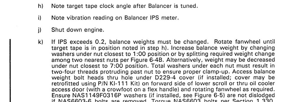
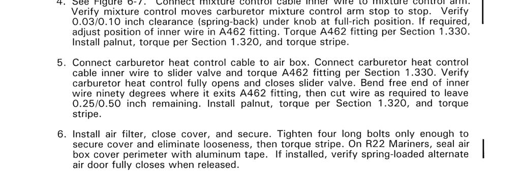
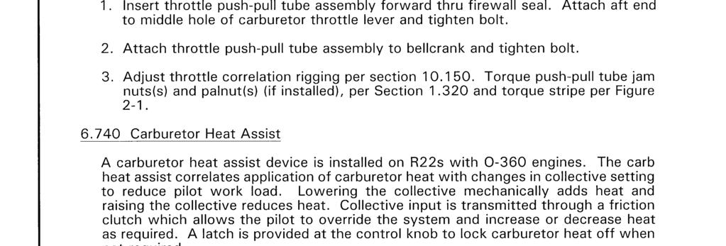
27 6.435 Air Filter Cleaning NOTE Replace B771-1 air filters after 5 years or 600 flight hours, whichever occurs first. 1. Remove B771-1 air filter from airbox. Visually inspect filter and verify no obvious damage. Inspect filter s pleated media for cleanliness. If the media contains only dust, clean media using compressed air or water. Clean heavily soiled media using a mild soap & water solution. a. Compressed air: Maintain at least one-inch distance between air nozzle and pleated media and apply less than 40 psi compressed air thru media opposite the normal direction of airflow. b. Water: Apply less than 40 psi water stream thru media opposite the normal direction of airflow. Dry filter thoroughly using less than 160 F warm air. c. Mild soap & water solution: Apply less than 40 psi water stream thru media opposite the normal direction of airflow. Soak filter in a mild soap and water solution for more than 15 minutes but less than 4 hours. Gently agitate filter in soap solution to help remove dirt. Apply less than 40 psi water stream thru media in both directions. Dry filter thoroughly using less than 160 F warm air. 2. Using a bright light, examine pleated media and verify no holes or tears. 3. Verify filter sealing surfaces are a smooth, continuous circle and flat. NOTE Do not install a wet air filter. Do not apply oil to filter media. 4. Install filter in airbox Carburetor Installation 1. With carburetor butterfly bellcrank on left, install carburetor and new gasket on mounting studs of engine sump and secure with washers and nuts. Special torque nuts per Install palnuts, standard torque per 1.320, and torque stripe. 2. Connect throttle push-pull tube to middle hole of carburetor butterfly bellcrank. Standard torque bolt per Install palnut, torque per 1.320, and torque stripe. 3. See Figure 6-7. Connect mixture control cable inner wire to carburetor mixture control arm. Lightly tighten A462 fitting, but do not torque; fitting will be torqued in following step. 4. Install air box per Verify idle RPM and idle mixture per Check throttle correlation rigging per OCT 2014 Chapter 6 Powerplant Page 6.21
28 6.450 Carburetor Heat Scoop Removal 1. Disconnect hose from carburetor heat scoop engine: Remove six screws securing curved sheet metal and remove sheet engine: Remove two B277 clamps securing scoop assembly to exhaust manifold and remove scoop engine: Remove four bolts securing scoop assembly to bead clamp on exhaust riser and remove scoop assembly. Remove additional clamp from exhaust riser above bead clamp Carburetor Heat Scoop Installation engine: Install A694 clamp and angle on #4 cylinder exhaust riser and lightly tighten. Attach scoop assembly on bead clamp and lightly tighten engine: Install scoop assembly, secure with B277 clamps, and lightly tighten. 2. Connect air inlet hose to scoop assembly engine: Position sheet on mounts. Move A694 clamp and rotate bead clamp (with attached scoop assembly) as required to minimize preload and ensure clearance from surrounding structure. Tighten A694 clamp. Standard torque bolts per Install sheet with six screws engine: Move scoop assembly as required to minimize preload and ensure clearance with surrounding structure. Special torque scoop attach clamps to 30 in.-lb Exhaust System Exhaust System Removal 1. Remove carburetor heat hose and, if installed, disconnect heater hoses from muffler shroud. 2. Protect landing gear aft cross tube with suitable covering. Disconnect exhaust flanges at cylinder heads and remove exhaust system and gaskets Exhaust System Installation 1. Position a gasket on each exhaust port. 2. Protect landing gear aft cross tube with suitable covering. Position exhaust system on engine and connect riser exhaust flanges to cylinder heads with washers and nuts. Remove protective cover from cross tube. 3. Loosen bead clamp on each riser. If required, remove curved metal sheet from carb heat scoop assembly. 4. Special torque exhaust flange nuts per Install palnuts and standard torque per Install carburetor heat hose and connect heater hoses, if installed. 6. Standard torque bead clamp AN3 bolts per If removed, install curved metal sheet on carburetor heat scoop assembly and reposition clamps as required to minimize preload and ensure clearance from surrounding structure. Page 6.22 Chapter 6 Powerplant OCT 2014
29
30
31
32
33
34
35
36
CHAPTER 29 HYDRAULICS Description Hydraulic Pump Hydraulic Reservoir Hydraulic Servos
 Section Title CHAPTER 29 HYDRAULICS 29-00 Description............................................... 29.1 29-10 Hydraulic Pump............................................ 29.1 29-20 Hydraulic Reservoir.........................................
CHAPTER 76 ENGINE CONTROLS. Section Title Page
 CHAPTER 76 ENGINE CONTROLS Section Title Page 76-00 Description........................................ 76.1 76-10 Fuel Control Unit (FCU)............................... 76.1 76-11 FCU Throttle Control
CHAPTER 63 MAIN ROTOR DRIVE SYSTEM
 Section Title CHAPTER 63 MAIN ROTOR DRIVE SYSTEM 63-00 Description............................................... 63.1 63-10 Engine Shaft Weldment...................................... 63.1 63-11 (Engine
Accident Prevention Program
 Accident Prevention Program Maintenance Aspects of Owning Your Own Airplane Introduction As an owner-pilot, FAR Part 43 allows you to perform certain types of inspections and maintenance on your airplane.
CHAPTER 13 INSTRUMENTS
 CHAPTER 13 INSTRUMENTS Section Title Page 13.000 Description.............................................. 13.1 13.100 Pitot-Static System......................................... 13.3 13.200 Primary Instruments........................................
CHAPTER 22 SERVICING
 CHAPTER 22 SERVICING Section Title 22-10 Main Rotor Gearbox......................................... 22.1 22-11 Cleaning Chip Detector..................................... 22.3 22-12 Cleaning Sight Gage.......................................
SECTION 4 NORMAL PROCEDURES CONTENTS
 CONTENTS Page Recommended Airspeeds....................... 4-1 Daily or Preflight Checks........................ 4-1 Before Starting Engine.......................... 4-6 Starting Engine and Run-Up......................
CHAPTER 21 ENVIRONMENT CONTROL. Section Title Page
 CHAPTER 21 ENVIRONMENT CONTROL Section Title Page 21-00 Description........................................ 21.1 21-10 Ventilation........................................ 21.3 21-11 Nose Vent................................
CHAPTER 79 ENGINE OIL SYSTEM
 Section Title CHAPTER 79 ENGINE OIL SYSTEM 79-00 Description............................................... 79.1 79-10 Scroll and Fanwheel Assemblies................................ 79.3 79-11 Fanwheel-to-Inlet
CHAPTER 13 INSTRUMENT SYSTEM
 CHAPTER 13 INSTRUMENT SYSTEM Section Title 13-00 Description............................................... 13.1 13-10 Pitot-Static System......................................... 13.3 13-20 Primary Instruments.........................................
SECTION 4 NORMAL PROCEDURES CONTENTS
 CONTENTS Page Recommended Airspeeds....................... 4-1 Daily or Preflight Checks........................ 4-1 Before Starting Engine.......................... 4-6 Starting Engine and Run-Up......................
SECTION 4 NORMAL PROCEDURES CONTENTS
 CONTENTS Page Recommended Airspeeds....................... 4-1 Daily or Preflight Checks........................ 4-1 Before Starting Engine.......................... 4-6 Engine Starting Tips...........................
TABLE of CONTENTS. Installation Instructions and Instructions for Continued Airworthiness PFS-17101
 TABLE of CONTENTS Section Page 1.0 Introduction... 3 1.1 Description... 3 1.2 Update Procedure... 3 2.0 Kit Contents... 4 3.0 Preparation... 5 4.0 Installation of PFS Exhaust System... 5 4.1 Installing
R22 PILOT'S OPERATING HANDBOOK ROBINSON HELICOPTER CO. AND FAA APPROVED ROTORCRAFT FLIGHT MANUAL RTR 061 TORRANCE, CALIFORNIA
 R22 PILOT'S OPERATING HANDBOOK AND FAA APPROVED ROTORCRAFT FLIGHT MANUAL RTR 061 FAA APPROVED IN NORMAL CATEGORY BASED ON FAR 27 AND FAR 21. THIS HANDBOOK INCLUDES THE MATERIAL REQUIRED TO BE FURNISHED
CARENADO COPYRIGHTS. Normal & Emergency Checklist
 NORMAL PROCEDURES CHECKLIST PREFLIGHT CHECK Control wheel -- RELEASE BELTS Avionics -- OFF Master Switch -- ON Fuel quantity gauges -- CHECK Master switch -- OFF Ignition -- OFF Exterior -- CHECK FOR DAMAGE
CHAPTER 12 SERVICING. Section Title Page
 CHAPTER 12 SERVICING Section Title Page 12-10 Main Rotor Gearbox.................................. 12.1 12-11 Servicing................................. 12.1 12-12 Filter Replacement...........................
CHAPTER 5 SINGLE-ROTOR POWER TRAIN SYSTEM MAIN DRIVE SHAFT FM 1-514
 CHAPTER 5 SINGLE-ROTOR POWER TRAIN SYSTEM A typical single-rotor power tram system (Figure 5-1) consists of a main transmission (main gearbox), a main drive shaft, and a series of tail rotor drive shafts
SERVICE INFORMATION LETTER
 SERVICE INFORMATION LETTER DATE: August 19, 2015 SERVICE INFORMATION LETTER NO. 0183 Page 1 of 18 1. SUBJECT: Collective Stick Socket Replacement 2. MODEL: F28A, 280, F28C, 280C, F28F, 280F, and 280FX
G-LAIN - Recurring Maintenance (All)
") MRB Daily inspection AD X Perform Annual inspection as per RHC R22 MM 2.400 and Lycoming OM, and CAA/LAMP/H/2007 Issue 1, First Aid Kit i.a.w. CAA/LAMP/H/2007, Issue 1, 12 MO 22-11-2016 22-11-2017 0 X
MRB Daily inspection AD X Perform Annual inspection as per RHC R22 MM 2.400 and Lycoming OM, and CAA/LAMP/H/2007 Issue 1, First Aid Kit i.a.w. CAA/LAMP/H/2007, Issue 1, 12 MO 22-11-2016 22-11-2017 0 X
CHAPTER 32 LANDING GEAR. Section Title Page
 CHAPTER 32 LANDING GEAR Section Title Page 32-00 Description........................................ 32.1 32-10 Landing Gear Assembly............................... 32.1 32-20 Cross Tubes.......................................
AA-5 SERIES MAINTENANCE MANUAL MODELS AA-5, AA-SA & AA-5B HOUR INSPECTION PROCEDURE ANNUAL OR 100 HOUR INSPECTION PROCEDURE GUIDELINE
 MODELS AA-5, AA-SA & AA-5B ANNUAL OR 100 - HOUR INSPECTION PROCEDURE ANNUAL OR 100 HOUR INSPECTION PROCEDURE GUIDELINE FAR 43 15 (C) (1) states: Each person performing an annual or 100 hour inspection
ENGINE ADJUSTMENTS. Remote Controls
 ENGINE ADJUSTMENTS Remote Control Wire Travel The remote control wire should measure 2.25 (54 mm) when extended outside the casing (Figure 2). After installation, the travel of the remote control wire
For Experimental Aircraft Only: Glastar, Sportsman 2+2, and Similar with Lycoming O320 or O360 Parallel Valve Engines
 REPORT NAME: KIT PFS-16104 INSTALLATION INSTRUCTIONS AND INSTRUCTIONS FOR CONTINUED AIRWORTHINESS APPROVAL PFS ENG DATE: REPORT NUMBER: PFS-16250-EXP REVISION: A REPORT DATE: 02/14/06 PREPARED BY: Tom
PIPER AIRCRAFT CORPORATION
 PA-28-181 INSPECTION REPORT ARCHER II ARCHER III PIPER AIRCRAFT CORPORATION (PART NUMBER 230 1039) PIPER AIRCRAFT CORPORATION INSPECTION REPORT This form meets requirements of FAR Part 43 Inspections must
SECTION 7 SYSTEMS DESCRIPTION CONTENTS
 CONTENTS Page General..................................... 7-1 Rotor Systems................................ 7-2 Drive System................................. 7-2 Powerplant..................................
CHAPTER 65 TAIL ROTOR DRIVE SYSTEM. Section Title Page
 CHAPTER 65 TAIL ROTOR DRIVE SYSTEM Section Title Page 65-00 Description........................................ 65.1 65-10 Tail Rotor Drive Fan Shaft.............................. 65.1 65-20 Tail Rotor
Seabee Annual Inspection Procedures
 Procedures Due to the wide variety of Seabee s flying out there, these procedures should be modified to fit YOUR Seabee. Make sure that all AD s are complied with as well as any required Service Bulletins
SECTION 2 LIMITATIONS
 GENERAL This section includes operating limitations, instrument markings, and basic placards required for safe operation of the helicopter, its engine, and other standard systems. This helicopter is approved
LANCAIR LEGACY PRE-TEST FLIGHT INSPECTION (8-04)
") LANCAIR LEGACY PRE-TEST FLIGHT INSPECTION (8-04) OWNER PHONE # ADDRESS N SERIAL # AIRCRAFT TYPE DATE / / TACH TIME hrs. TOTAL TIME hrs. EMPTY WEIGHT CG. PAINT & INTERIOR? YES NO ENGINE TYPE PROPELLER ALL
LANCAIR LEGACY PRE-TEST FLIGHT INSPECTION (8-04) OWNER PHONE # ADDRESS N SERIAL # AIRCRAFT TYPE DATE / / TACH TIME hrs. TOTAL TIME hrs. EMPTY WEIGHT CG. PAINT & INTERIOR? YES NO ENGINE TYPE PROPELLER ALL
Vso 61. Vs1 63. Vr 70. Vx 76. Vxse 78. Vy 89. Vyse. 89 (blue line) Vmc. 61 (radial redline) Vsse 76. Va 134) Vno 163
 Vmc. 61 (radial redline) Vsse 76. Va 134) Vno 163") PA34-200T Piper Seneca II Normal procedures V-speeds Knots Vso 6 Vs 63 Vr 70 Vx 76 Vxse 78 Vy 89 Vyse Vmc 89 (blue line) 6 (radial redline) Vsse 76 Va 2-36(@4507lbs 34) Vno 63 Vfe 38 (0*)/2(25*)/07(40*)
PA34-200T Piper Seneca II Normal procedures V-speeds Knots Vso 6 Vs 63 Vr 70 Vx 76 Vxse 78 Vy 89 Vyse Vmc 89 (blue line) 6 (radial redline) Vsse 76 Va 2-36(@4507lbs 34) Vno 63 Vfe 38 (0*)/2(25*)/07(40*)
INTRODUCTION. This Catalog:
 Editor s Note: This Parts Catalog has been reproduced from the original Republic Parts Catalog. Obviously, most of the information is obsolete; the pictures are accurate and up-to-date. If nothing else,
Jump to Table of Contents
 Jump to Table of Contents PIPER AIRCRAFT CORPORATION PA-28R-201, CHEROKEE ARROW III SECTION 3 EMERGENCY PROCEDURES 3.3 EMERGENCY PROCEDURES CHECK LIST ENGINE FIRE DURING
R22 PILOT'S OPERATING HANDBOOK ROBINSON HELICOPTER CO. AND FAA APPROVED ROTORCRAFT FLIGHT MANUAL RTR 061 TORRANCE, CALIFORNIA
 R22 PILOT'S OPERATING HANDBOOK AND FAA APPROVED ROTORCRAFT FLIGHT MANUAL RTR 061 FAA APPROVED IN NORMAL CATEGORY BASED ON FAR 27 AND FAR 21. THIS HANDBOOK INCLUDES THE MATERIAL REQUIRED TO BE FURNISHED
CHAPTER 33 ELECTRICAL SYSTEM
 CHAPTER 33 ELECTRICAL SYSTEM Section Title Page 33-00 Description.............................................. 33.1 33-10 Battery................................................. 33.2 33-20 Clutch Actuator...........................................
CIRRUS AIRPLANE MAINTENANCE MANUAL
 POWER CONTROL. DESCRIPTION This section describes those components which furnish a means of controlling engine power. Engine controls for the airplane include the following: control quadrant, throttle
Robinson R44. Systems
 Robinson R44 Systems The airframe is primarily a metal construction. The primary fuselage is welded steel tubing and riveted aluminium sheet. The tailcone is an aluminium semi-monocoque structure where
CHAPTER 3 LIFE-LIMITED COMPONENTS
 Section Title CHAPTER 3 LIFE-LIMITED COMPONENTS 3.000 Life-Limited Components...................................... 3.1 3.001 Introduction............................................. 3.1 3.002 Time-In-Service
PREFLIGHT CHECK COCKPIT RIGHT WING. NORMAL PROCEDURRES CHECKLIST PA-28RT 201 Arrow IV
 NORMAL PROCEDURRES CHECKLIST PA-28RT 201 Arrow IV PREFLIGHT CHECK COCKPIT Control Wheel -- Release Restraints Avionics -- OFF Parking Brake -- SET All Switches -- OFF Mixture -- IDLE CUT-OFF Master Switch
TABLE of CONTENTS. PFS REV C Page 2 of 20 05/22/07
 Section TABLE of CONTENTS Pages Introduction 3 Kit Contents 4 Preparation 5 Removal of old exhaust system 5 Installation 5 Installing Collector Box Assembly and Exhaust Assembly 5 Installing Cabin Heat
PIPER CUB J3-65 N68952 PRE-FLIGHT CHECKLIST COCKPIT
 PIPER CUB J3-65 N68952 PRE-FLIGHT CHECKLIST COCKPIT Check airworthiness certificate, registration, weight & balance documentation Battery - CONNECTED Plug in headsets or secure as required Fuel ON Magnetos
CHAPTER 8 WEIGHT AND BALANCE. Section Title Page
 CHAPTER 8 WEIGHT AND BALANCE Section Title Page 8-10 Leveling.......................................... 8.1 8-11 Leveling for Weight and Balance................. 8.1 8-12 Leveling for Rigging..........................
RAF BULLDOG MODIFICATION INDEX T Mk 1 SERIES
 RAF BULLDOG MODIFICATION INDEX T Mk 1 SERIES ification Title Class Comments 1 1.4.73 Extension of Flap Shrouds B2 2 4.4.73 Resistor Part No 11212E (ITT Ltd) in Supply to Integral Lighting on CCS Panel
CHAPTER 3 LIFE-LIMITED COMPONENTS
 CHAPTER 3 LIFE-LIMITED COMPONENTS Section Title 3.100 Life-Limited Components..................................... 3.1 3.110 Time-in-Service Records................................... 3.1 3.120 Fatigue
Power Flow System Extractor Exhaust System Installation Instructions Cessna 172, 175 TABLE OF CONTENTS
 Heading Power Flow System Extractor Exhaust System Installation Instructions TABLE OF CONTENTS Pages Introduction 3 Kit Contents Classic Tailpipes 4 Kit Contents Short Stack Tailpipes 5 Preparation 6 Removal
A4_12ppAviation_doc2spot 3/2/05 10:20 AM Page 2 NOICE, THANK YOU
 NO ICE, THANK YOU NO ICE, THANK YOU Contents PROFILE INTRODUCTION ICING AREAS WITHIN THE CARBURETTOR PILOT DEFENCE EQUIPMENT INFORMATION FOR THE HELICOPTER PILOT How, When and Why PREVENTION Ground checks
PIPER CUB J3-65 N68952 PRE-FLIGHT CHECKLIST
 PRE-FLIGHT CHECKLIST COCKPIT Check airworthiness certificate, registration, weight & balance documentation Battery - CONNECTED Plug in headsets or secure as required Fuel ON Primer CLOSED & LOCKED Carb
Chapter 73. Engine Fuel and Control
 Chapter 73 Engine Fuel and Control PAGE 1 Table of Contents Chapter Title 73-20-00 CONTROLLING............................. 3 73-20-10 Throttle..................................... 3 73-20-11 Throttle
CIRRUS AIRPLANE MAINTENANCE MANUAL
 POWER PLANT 1. GENERAL This chapter describes maintenance practices for the airplane systems which provide the means to induce and convert fuel-air mixture into power such as the engine, baffling, cowling,
Models AA-5, AA-5A & AA-5B Annual or 100-hour Inspection
 Models AA-5, AA-5A & AA-5B Registration Number Serial Number Hours Registered Owner(s) Street Address City State/ Postal Code Provence Inspector Signature License No. Date Airport/City State/ Provence
CHAPTER 1 GENERAL. Section Title
 Section Title CHAPTER 1 GENERAL 1.000 Introduction.............................................. 1.1 1.001 R22 Maintenance Manual Revisions............................ 1.1 1.002 R22 Maintenance Authorization...............................
SPECIFICATIONS TEST AND ADJUSTMENT SPECIFICATIONS SPECIFICATIONS ENGINE FD620D, K SERIES
 TEST AND ADJUSTMENT Engine Oil Pressure Sensor Activates............................... 98 kpa (14.2 psi) Oil Pressure While Cranking (Minimum).......................... 28 kpa (4 psi) Oil Pressure.....................................
CHAPTER 9 GROUND HANDLING. Section Title Page
 CHAPTER 9 GROUND HANDLING Section Title Page 9-10 Ground Handling.................................... 9.1 9-11 Ground Handling Wheels...................... 9.1 9-12 Moving Helicopter on Ground Handling
CHAPTER 8 FLIGHT CONTROLS
 Section Title CHAPTER 8 FLIGHT CONTROLS 8.000 Flight Controls............................................ 8.1 8.001 Introduction............................................ 8.1 8.002 Description.............................................
TB90BC 41ADT90C711 Page 1 of 6 Boom & Trimmer
 TB90BC 41ADT90C711 Page 1 of 6 Boom & Trimmer TB90BC 41ADT90C711 Page 2 of 6 Boom & Trimmer 1 791-00040 1 Throttle Housing Assembly (includes 2-4) 2 791-00041 1 Throttle Trigger Lock-Out 3 791-00042 1
CHAPTER 18 WEIGHT AND BALANCE
 CHAPTER 18 WEIGHT AND BALANCE Section Title 18-10 Leveling................................................. 18.1 18-11 Leveling at Lower Right Side Frame Tube & Aft Landing Gear Cross Tube.. 18.1 18-12
PIPER AIRCRAFT PA NOTE- Perform all inspections or operations at each oj the inspection. 1. Inspectspinnerandbackplate
 PPER ARCRAFT PA-38-111 (.MANTENANCE MANUAL SCHEDULED MANTENANCE. PERODC NSPECTONS. -NOTE- Perform all inspections or operations at each oj the inspection intervals as indicated by a circle (). nspection
CHAPTER 63 MAIN ROTOR DRIVE SYSTEM. Figure Title Page 63-1 Main Rotor Gearbox and Mast Assembly Main Rotor Gearbox Installation
 CHAPTER 63 MAIN ROTOR DRIVE SYSTEM Figure Title Page 63-1 Main Rotor Gearbox and Mast Assembly...................... 63.0 63-5 Main Rotor Gearbox Installation............................. 63.4 63-7 Rotor
Printed from MediaCat
 Illustration A Crankcase Illustration A Crankcase Ref.Nr. Item code Quantity Description 1 1106 020 2506 1 Crankcase (2) 2-11 2 0000 988 5217 1 Connector (2) 3 0000 988 5200 2 Connector (2) 4 1106 641
R22 PILOT'S OPERATING HANDBOOK ROBINSON HELICOPTER CO. AND FAA APPROVED ROTORCRAFT FLIGHT MANUAL RTR 061 TORRANCE, CALIFORNIA
 R22 PILOT'S OPERATING HANDBOOK AND FAA APPROVED ROTORCRAFT FLIGHT MANUAL RTR 061 FAA APPROVED IN NORMAL CATEGORY BASED ON FAR 27 AND FAR 21. THIS HANDBOOK INCLUDES THE MATERIAL REQUIRED TO BE FURNISHED
ADVANCED TECHNOLOGY. Automatic Clutch Engagement. Simplifies startup procedure and reduces the possibility of an overspeed.
 ADVANCED TECHNOLOGY Advanced Warning Devices. The instrument panel includes low fuel warning light, main gearbox temperature and chip lights, tail gearbox chip light, low oil pressure light, engine fire
Mooney Mite M-18X Plans and Drawings Index Arranged by Group Miscellaneous Group
 Miscellaneous Group 110470 Bushings - Special 314410 Airspeed & Altimeter Installation 110190 Arm - Landing Warning 110070 Button - Static Airspeed 213260 Cone - Wing Fillet 110120 Control - Placard 616100
CIRRUS AIRPLANE MAINTENANCE MANUAL
 AIR INTAKES 1. DESCRIPTION This section describes that portion of the power plant which directs mass air flow to the engine. Induction air enters the engine through a filter mounted on the right, aft side
Drawing A Crankcase 041 AV SCS
 Drawing A Crankcase 1 Drawing A Crankcase Reference Item number Qty Description 1 1110 020 2105 1 Crankcase 2-5, 9, 10, 12 2 9371 470 3120 2 Cylindrical pin 6x20 3 9048 216 1010 8 Pan head screw M5x18
INSTALLATION MANUAL EAGLE EMS ELECTRONIC ENGINE MANAGEMENT SYSTEM EMSINSTL001 REV 0.2 2/12/08
 INSTALLATION MANUAL EAGLE EMS ELECTRONIC ENGINE MANAGEMENT SYSTEM EMSINSTL001 REV 0.2 2/12/08 The information contained in this publication is intended as a guide to install your Eagle EMS Engine Management
100hr and Condition inspection checklist
 100 Hour and Annual Inspection Guide 100hr and Condition inspection checklist AA-100CONISP-LS1 Revision Date Details 0 4-2009 Original 1 4-2012 Format change AA-100CONISP-LS1 R1-4-2012 100 Hour and Annual
SPECIFICATIONS TEST AND ADJUSTMENT SPECIFICATIONS SPECIFICATIONS ENGINE FD620D, K SERIES
 ENGINE FD620D, K SERIES SPECIFICATIONS SPECIFICATIONS TEST AND ADJUSTMENT SPECIFICATIONS Engine Oil Pressure Sensor Activates............................... 98 kpa (14.2 psi) Oil Pressure While Cranking
SECTION 3. EXHAUST SYSTEMS
 9/8/98 AC 43.13-1B 8-45. GENERAL. Any exhaust system failure should be regarded as a severe hazard. Depending upon the location and type of failure, it can result in carbon monoxide (CO) poisoning of crew
NOTE. KI & KI Revision H
 KI-179-5 & KI-179-7 R22-series Kannad AF Integra ELT Installation Kit Instructions For R22 helicopters without ELTs or if replacing previously installed Pointer 3000-10 or 4000-10 ELT (RHC Inst l) NOTE
C I R R U S CONTROLLING DESCRIPTION
 CONTROLLING 1. DESCRIPTION Serials 22-0002 & subs: An electric two-speed fuel pump provides boost (low speed) and prime (high speed) for the engine. A console mounted rocker switch located on the center
1983 Mazda RX-7 GSL TUNE-UP' 'Mazda Rotary
 TESTING ENGINE COMPRESSION The manufacturer recommends using a special compression tester (49 0820 280K). Compression testers for piston engines will read only the highest pressure of the 3 combustion
INSTALLATION MANUAL FOR JABIRU 5100 AIRCRAFT ENGINE
 INSTALLATION MANUAL FOR JABIRU 5100 AIRCRAFT ENGINE This Manual has been prepared as a guide to correctly install the Jabiru 5100 engine into an airframe. Should you have any questions or doubts about
a. Lycoming IO-520J 250 HP c. Lycoming O-540-J3C5D 235 HP b. Continental O450T 330 HP d. Lycoming O-360A 180 HP
 Three points each question Page 1 of 6 References: Pilot's Operating Handbook for the 1979 Cessna R182 Model; Flying Magazine Article "Cessna 182 Safety Report;" RAFA SOP; and Refueling Instructions found
C I R R U S DISTRIBUTION DESCRIPTION
 MODELS SR AND SRT DISTRIBUTION. DESCRIPTION This section contains information on the distribution system. The fuel distribution system consists of electric and mechanical (engine-driven) fuel pumps, fuel
Illustrated Parts List
 FORM MS 0670 3C 8/2001 REPLACES FORM MS 0670 2Q 11/2000 FILE IN SECT. 2 OF SERVICE MANUAL Illustrated Parts List Model Series TYPE NUMBERS 0042 through 1256. For Use On Engines Built Before Date Code 01070100.
Illustrated Parts List to
 TYPE NUMBERS 0101, 0102, 0106, 0108, 0109, 0115 through 0224, 0415, 0418, 0467, 0468, 0601 through 0683, 3101 through 3108, 3110 through 3163, 3167 through 3181. Illustrated Parts List Model Series 124700
COMER SW80 TECHNICAL SPECIFICATIONS
 UPDATED JANUARY 2012 Preamble: SW 1.01 SW 1.02 The following are the Technical Specifications for the engine, as approved by the Australian Karting Association. This engine is approved for use in the CADET
Nikki Carburetor Vertical Models , ,
 Nikki Carburetor Vertical Models 280000, 310000, 330000 Disassemble Carburetor 1. Remove fuel bowl screws (A, Figure 56). Remove the fuel bowl (B) from the carburetor body. WARNING Before servicing the
PA34-220T Piper Seneca III
 PREFLIGHT PA34-220T Piper Seneca III Weight and Balance Documents -Airworthiness Certificate -Registration -Airplane Flight Manual -Weight & Balance Hobbs/Time Landing Gear Avionics and Fan(s) Cowl Fuel
Cessna 172RG WARNING. Maximum Demonstrated Crosswind. Takeoff or landing..15 KTS
 Cessna 172RG INTRODUCTION: This aircraft checklist contains information from the original manufacturer s Pilot Information Manual. Normal procedures associated with optional systems can be found in Section
PA32-RT LANCE II CHECKLIST
 PA32-RT LANCE II CHECKLIST 6815.10.1112 1 Normal Procedures PREFLIGHT CHECK Control Wheel... RELEASE BELTS Parking brake... Set Master Switch... ON Fuel Quantity Gauges... check Master Switch... OFF Ignition...
Maintenance Instruction 23.1
 Subject: Replacement of engine GROB 2500 E1/D1 by engine LIMBACH L 2400 EB1.AA Affected Aircraft: Motor glider GROB G 109 (B) Aircraft: Type G 109 (B) Registration Propeller: Type MTV-1-A/L160-03 Serial
Van s Aircraft RV-4. Pilot s Operating Handbook
 Van s Aircraft RV-4 Pilot s Operating Handbook PERFORMANCE SPECIFICATIONS SPAN:.. 23 0 LENGTH:. 19 9 HEIGHT:. 6 8 SPEED: Maximum at Sea Level.. Cruise, 75% Power at 8,000 Ft.. 173 Knots 165 Knots RANGE
COMPONENT IDENTIFICATION
 This CFMI publication is for Training Purpose Only. The information is accurate at the time of compilation; however, no update service will be furnished to maintain accuracy. For authorized maintenance
Section 10 Chapter 17
 Section 10 Chapter 17 24 Valve, 8.3 Liter Engine Air Intake System Note: All coding used in the 8.3 Liter and 9 Liter engine manuals are Cummins engine codes. These engine codes have no meaning to New
Illustrated Parts List to
 Illustrated Parts List Model Series 124800 to 124899 FORM MS-2436-9/94 REPLACES FORM MS-2436-10/93 FILE IN SECT. 2 OF SERVICE MANUAL 124800 to 124899 TYPE NUMBERS 0106, 0206 through 0284, 0406 through
REF. NO. DESCRIPTION TOP COWLING 2 MOLDING, AIR DUCT 3 RIVET 4 SEAL 5 HOLDER, CLAMP BAND 6 BOLT, WITH WASHER 7 HOOK
 SUZHOU ALLPASS MACHINERY CO.,LTD Add:No.85,Jishui Road,Jinfeng Industrial Park,Mudu Town,Suzhou 215102,Jiangsu,P.R.China T15 SPARE PARTS EXPLODED DRAWING FIG. 1 1 TOP COWLING TOP COWLING 2 MOLDING, AIR
FREEDOM Model #W035297DA Model #W035297IA. E 2002 Polaris Sales Inc. PARTS MANUAL PN and MICROFICHE PN /02
 FREEDOM Model #W0DA Model #W0IA E 00 Polaris Sales Inc. PARTS MANUAL PN 0 and MICROFICHE PN 0 /0 TABLE OF CONTENTS FREEDOM W0DA and FREEDOM W0IA Parts Manual BATTERY... BILGE PUMP... CARBURETOR... COOLING
Illustrated Parts List
 FORM MS 2264 07/20/2005 REPLACES FORM MS 2264 03/04/2005 FILE IN SECT. 2 OF SERVICE MANUAL 350700 Illustrated Parts List Model Series 350700 TYPE NUMBERS 0034 through 1171. TABLE OF CONTENTS Air Cleaner.........................
Tillotson Tc3A Carburator
 Tillotson Tc3A Carburator 176 FUEL SYSTEMS - 5B-11 CENTER BOWL TYPE CARBURETOR Removal 1. Remove front cowl cover and wrap-around cowl. 2. Remove swivel link from lower carburetor. (Figure 2) 3. Loosen
SECTION 4 - FUEL SYSTEMS AND CARBURETION
 SECTION - FUEL SYSTEMS AND CARBURETION FUEL SYSTEMS - - - - - - - - - - - - - - - - - - - - - - - - - - - - - - - - - - - - - - - - - - - - - - - - - - - - - - - - - - - - - -62 FUEL PUMP - - - - - - -
Power Max Commercial 1028 OHXE Snowthrower
 Form No. 3415-768 Rev B Power Max Commercial 1028 OHXE Snowthrower Model No. 38806 Serial No. 400000000 and Up Register at www.toro.com. Original Instructions (EN) *3415-768* B Ordering Replacement Parts
Elmendorf Aero Club Aircraft Test
 DO NOT WRITE ON THIS TEST FEB 2013 Elmendorf Aero Club Aircraft Test Cessna 172RG For the following questions, you will need to refer to the Pilots Information Manual for the C-172RG and the Auxiliary
GENERAL The Honeywell model TFE731-40AR turbofan engine is a lightweight, two-spool, geared-stage, front-fan, jet engine.
 ENGINE GENERAL The Honeywell model TFE731-40AR turbofan engine is a lightweight, two-spool, geared-stage, front-fan, jet engine. The cross section of the engine is shown in Figure 7-71-1, page VII-71-3.
Super 1050 Chain Saw UT Page 1 of 16 Carburetor Chamber
 Super 1050 Chain Saw UT-10139 Page 1 of 16 Carburetor Chamber Super 1050 Chain Saw UT-10139 Page 2 of 16 Carburetor Chamber 1 58319A 1 RING- Retaining 2 592301 1 COVER- Air filter 3 A70326 1 NUT- Cover
Revision Control Page REPORT PFS Kit PFS REVISION DATE REMOVE PAGES
 Revision Control Page REPORT PFS-0020-00 Kit PFS-13203 REVISION DATE REMOVE PAGES INSERT PAGES IR 06/27/00 N/A N/A A 09/21/00 1,2,4,14 1,2,4,14 B 02/12/01 1,2,4,8,9,13 1,2,4,8,9,13 C 09/14/01 1,2,3,4,5,6,7,8
Illustrated Parts List
 FORM MS 4183 10/31/2006 REPLACES FORM MS 9748 7/1997 FILE IN SECT. 2 OF SERVICE MANUAL 290700 Illustrated Parts List Model Series 290700 TYPE NUMBERS 0100, 0102, 0106, 0107, 0108, 0333, 0402, 0410. TO
CESSNA 182 CHECKLIST. LEFT WING Trailing Edge 1. Aileron CHECK freedom of movement and security
 CESSNA 182 CHECKLIST PRE-FLIGHT INSPECTION CABIN 1. Pilot s Operating Handbook AVAILABLE IN THE AIRPLANE (A.R.R.O.W.E) 2. Landing Gear Lever DOWN 3. Control Wheel Lock REMOVE 4. Ignition Switch OFF 5.
Illustrated Parts List
 FORM MS 0670 08/09/2006 REPLACES FORM MS 0670 05/01/2006 FILE IN SECT. 2 OF SERVICE MANUAL 351400 Illustrated Parts List Model Series 351400 TYPE NUMBERS 0042 through 1256. TABLE OF CONTENTS Air Cleaner.........................
2.0 KIT CONTENTS INSTALLATION OF PFS EXHAUST SYSTEM INSTRUCTIONS FOR CONTINUED AIRWORTHINESS PASSENGER SIDE VIEW...
 TABLE of CONTENTS 1.0 INTRODUCTION... 3 1.1 GENERAL... 3 1.2 DESCRIPTION... 3 1.3 UPGRADES... 3 2.0 KIT CONTENTS... 4 2.1 CLASSIC TAILPIPE KITS... 4 2.2 SHORT STACK TAILPIPE KITS... 5 3.0 PREPARATION...
RIGHT LEFT. Fig. 9. Fig. 10. Page.33
 Remark : The coupling sleeve of the magneto is installed with the marking from the rubber part facing the magneto gear. 9.4.3.6 Carefully remove the magneto from the engine ; screw the nut of the coupling