TentLabs DIY CD player Assembly manual V1.2
|
|
|
- Valentine Washington
- 5 years ago
- Views:
Transcription

1 TentLabs DIY CD player Assembly manual V1.2 2
2 Disclaimer Electrical safety Within the equipment, during building and surely when finished, AC mains voltages and high DC voltages exist. Care should be taken as long as the cabinet is not closed and the equipment is been connected to the mains. The user remains responsible for his own and others safety and damage of the equipment. Following the instructions however will avoid hazard and electrical shock. Mechanically Assembling the kit you will be handling metal parts that may cause injuries if not handled carefully. Moreover you will use tools. Be aware of this. Warrantee The content of this kit has been assembled with great care. All modules and parts have been tested prior to shipping. If assembled according these instructions, the equipment will work. The warrantee on the modules is as following CDpro drive: No warrantee. Philips requires the CDpro to be mounted in a professional environment, which isn t the case with DIY Tentlabs modules: 5 year assumed built in according instruction Mechanical parts: 5 years assumed built in according instructions Exceptions: Tubes, these carry 6 months warrantee. Moving parts, these carry 1 year warrantee. Liability Tentlabs accepts no liability at all from any potential damage or injury that may occur when assembling, connecting or using the CD player or any of its sub parts and assemblies. 3
3 1. Preparation You bought you a kit that will give you a great satisfaction because of the excellent performance, when finished. Assembling the DIY-kit is great fun if you are prepared to the job. Therefore some words in advance: Assure that the place to work will be large enough and sufficiently lightened. The table you will be working on should be covered with a soft cloth to avoid scratches on the case parts of the equipment. To avoid parts scattering around during assemblage, it is a good habit to use some fist-sized (plastic) boxes to temporarily store the components from each bag of the kit. (Make sure not to mix the parts) To keep a good overview, assure another place to display all the kit parts and tools to be used. Make sure you will not be disturbed by others who have no idea of what you are doing. Keep them away for their and your safety, especially children! Finally, first read the total instructions in this manual, until the last page. This will give you a good idea of the expected building phases. Missing parts In case you miss some parts, please do not hesitate to contact me. The kit has been prepared with great care, but errors are only human. Maintenance The kit requires little maintenance. The metal parts can be cleaned with a soft cloth. The wooden side panels can be oiled using any regular furniture maintenance oil. We used to ship this with the kit, but international regulations have changed and since the oil is flammable.. The IV stage input offset can be checked every year, using the procedure described at page 70. We do not include a mains power chord as: - Plugs differ from country to country - You usually have a few lying around - Most customers prefer some special audio cable of their own preference 4
 5.")
4 1.1. Required tools Depending on your experience and your tool-kit, you will be able to assemble this DIY kit within four to eight hours. The following tools are needed: 1. A crosshead screwdriver PH1 and/or PZ1 2. A crosshead screwdriver PH2 and/or PZ1 3. A flathead screwdriver size 2 4. Set of metric wrenches (8, 10, 11, 12 and 13) 5. A soldering iron (50 watt, small tip) 6. Solder (0,5 to 1 mm, with flux) 7. A pair of tweezers 8. A small wire cutter 9. Some wire stripper 10. Straight nose pliers 11. Socket spanners (metric 5 and 5,5 mm) 12. A cheap multi meter for AC and DC voltages. 13. Contact adhesive, based on synthetic rubber. 5

5 1.2. How a nearly assembled player will look like It is convenient to know where to end, before one begins. For this purpose, below picture is inserted. This is the kit built up to the stage of mounting the front panel and the sledge support bridge General instructions Never use excessive force to get things in place or when tightening nuts or bolts. If things do not fit easily, something must be wrong. Check connections when made and double check them prior to the first operation. Ask someone else to check all wiring using the photographs and pictures in this depiction as a reference. In doubt, contact us using info@tentlabs.com or Have fun! December 2007, Guido Tent. 6
6 2. Base Plate (Labels) Prior to mounting any module or part, the labels on the back need to be put on. These labels are aluminum foil, and need to be put exactly in place. As of March 20, these labels are not yet available but will be shipped later. This shipment includes instructions for use. 7


7 2. Base Plate (Chassis) Take the base plate and bag 2. Put the contents of the bag in a box. Put the base plate on its rear side. Use the three transformers to stabilize the setting. Fix 24 studs with 24 M3*6 mm chrome crosshead bolts using the 5,5 mm socket spanner and or the crosshead screwdriver. Be aware that there are more holes than studs. Watch the pictures beside. Put the rest of the components back in bag 2 or set the box aside if you use more than one temporary box. Put the chassis at its bottom. Take bag 1 and put the contents in a box. Take the red and black RCA connectors and mount these as shown in the picture beside. Use the colored insulators at the correct position (The red connector is fixed at the right, seen from the inside) and assure that the solder tags point towards each other. Mount the BNC connector in the next flattened hole using the large washer between the chassis and the tag with the large hole. Take the 3 mm solder tag, an M3*6 mm bolt, a toothed washer out of the box and an M3 nut (from bag 2). Fix the tag to the 3 mm hole over the RCA connectors; The toothed washer shall be between the tag and the chassis. The tag "should point to about five o'clock". Take the 100 nf capacitor; bend and cut the wires before soldering. See the picture beside. 8


8 Take the mains entry, remove the fuse holder and mount two fuses into the mains entry. (One fuse is spare.) Fuse values are: 115V mains 230V mains 630mA slow blow 315mA slow blow Mount the pre-assembled IEC mains entry to the base plate chassis with the switch upwards. Press it tightly until it snaps into. Check with an IEC connector that the entry does not hatch if pulled out. Take the 4 rubber feet and 4 M4*8 black bolts. Fix the feet to the bottom of the chassis. Do it gently because of the soft rubber and the thread in the aluminum chassis. Of course you could fit alternative feet if required. Bag 1 should be empty now. 9


 over the just fixed bolts. Mind that the larger washer corresponds with the cutouts.")
. The other 2 transformers are equal; the one with the shorter wiring goes in the middle.")
9 3. Preparing the Sides The sides are built up of metal parts covered with wood. The sides are each other's mirror image, and packed as such so be careful not to mix them. Take the metal sides and wooden panels, the three transformers and bag #4. Take the parts out of the bag and put them in a box. Take the transformers: TR1 = box #13 TR2 = box #12 TR3 = box #14 Out their boxes, and open the small bags from boxes #12 and #13. These contain bolts, neoprene washers and metal disks. Open these bags and also take out two M5*40 bolts and two M5 nuts. Take the metal side with the three large centered holes. Fix all three bolts and nuts firmly with the 8 mm wrench (see picture). Put the three washers (one larger than the other two) over the just fixed bolts. Mind that the larger washer corresponds with the cutouts. Place the three transformers such that transformer #14 corresponds with the larger washer (see picture) and keep the rotation of them as in the pictures (all wiring to the same direction). The other 2 transformers are equal; the one with the shorter wiring goes in the middle. Fix on top of the transformers respectively a neoprene washer, a disc and an M5 locknut (out of the bag #4). Do not tighten the locknuts too much because of precise alignment of the transformers later on, but make sure the wiring more or less points to the right referred to the picture on the right. 10


10 Mount this assembled metal side on the corresponding wooden side. Both metal and wood are mirror matched so mind the small holes in the wood: they should correspond with the holes in the metal side. Take care not to clasp the transformer's wiring between the metal and the wood. Bag #4 contains 12 screws to fix the metal to the wooden sides. Do not use excessive force when mounting these screws. 11


11 4. Mains- and Regulator PCB's Take box #5 containing three preassembled modules and a bag with a bare PCB and parts. The modules are voltage regulator boards and the bare one becomes the so called 'mains PCB' Mains PCB You will first assemble this mains PCB. The parts will be placed at the text side of the PCB. Put the small (grey) block capacitor in position C1, turn the PCB, solder C1 and cut the remaining wires. Repeat for the diode. The black ring on the diode shall correspond with the ring of D1, as marked on the PCB and the layout shown right. Next, place the orange relay on position K1 turn the board and solder. Mount the 4 PCB connectors at J1, J2, J3 and J4 with their entries pointing outwards. Press them firmly to the board during soldering. Mount the 2 pole connector at J5, in a similar way Fixing the regulators and mains PCB's to the chassis Temporarily place the PCB's on the studs on the chassis as in the picture: - The mains PCB at the front side and the regulators in sequence 5 V, 9 V and 5 V. - Watch the rotation of all modules, as on the picture right You can recognize the regulators by the hand written inscription at the top of the PCB. Secure all modules with one nut each (out of bag #2). 12


 into the rear. Lastly, fix (still loosely) the three M3*6 bolts from the base side.")
12 5. Mounting the left side Take the assembled left side and put it next to the left of the chassis with the big transformer to the rear. In the box are still the remaining parts of bag 4. Take 4 bolts M3*6 and one bolt M3*16 from bag #4. Carefully put the side in place on the chassis without scratching it. It would be nice if the supple brown mains cord passed through the little space between the big transformer, the side and the chassis. The cut-away allows this. Take care not to clasp any wiring. Take the M3*16 bolt and fix it loosely in the upper position in the rear side, as shown right. This bolt is longer, on purpose, as to mount the safety earth tag later, from the inside. Next fit another bolt (M3*6) into the rear. Lastly, fix (still loosely) the three M3*6 bolts from the base side. If everything fits correct, and no wiring is squeezed between side and base panel, gently fasten the bolts starting at the top of the rear up to the front of the chassis. 13


.")

13 6. Wiring the Mains Connections 6.1. Mains entry Strip the mains cord from the entry (brown sleeve). Strip about 6 mm, twist the bare wiring firmly, fold the ends and fit them to the input of the mains PCB. The order (blue/brown) is of no importance. For the ease of connection, the mains PCB could be taken from its studs after loosing the nut Safety earth tag Strip 5 mm the outer end of the yellow / green earth cable from the mains entry, and pre-tin that wire Take the M3 tag, and solder it to the tag. Put a toothed M3 washer on the M3*16 bolt (from the inside). Fix the yellow / green mixed wire with its tag to the M3*16 bolt, add an M3 nut and tighten it well Wiring the primary connections of the transformers To correctly wire the transformers, you must know the mains voltage your CD player will be connected with. 210 to 240 Vac => wire for 230 volt, 105 to 120 Vac => wire for 115 volt. Prepare by cutting off the soldered ends of all the leads of transformers TR1 & TR2 and strip these again (about 6 mm). Do 14
 of the transformers will be helpful. Of course this is a question of taste, it is up to you. Take your chance!")


14 6.3.1 Wiring Transformers for 230 V Lead the primary cords between the studs of the (to be mounted) regulator PCB's as much as possible for the look of the things. Also the position (rotation) of the transformers will be helpful. Of course this is a question of taste, it is up to you. Take your chance! TR3 Grasp the four primary wires in the white sleeve and twist the bare ends of the white and orange wires firmly together, fold them double and connect this to the middle contact of connector labeled as 'TR3' on the mains PCB. The remaining wires are firmly twisted, folded double and connected to the outside connections of connector 'TR3'. TR2 (middle transformer) Grasp the four primary wires in their black socks. Twist purple and grey together (as depicted above) and fix them into the middle of connector 'TR2' on the mains PCB. Connect the blue and brown wires to the outside connections of connector 'TR2' on the mains PCB. TR1 Grasp the four primary wires in the black socks. Twist purple and grey together (as depicted above) and fix them into the middle of connector 'TR1' on the mains PCB. Connect the blue and brown wires to the outside connections of connector 'TR1' on the mains PCB. 15

 are firmly twisted together, folded double and connected to the other outside connection of conductor 'TR3'.")
 and fix them to one of the outside contacts of connector 'TR2' on the mains PCB.")
15 6.3.2 Wiring Transformers for 115 V Lead the primary cords between the studs of the (to be mounted) regulator PCB's as much as possible for the look of things. Also the rotation of the transformers will help. TR3 Grasp the four primary wires in the white socks. Twist the bare ends of the purple and orange wires firmly together, fold them double and connect this to one of the outside contacts of connector labeled as 'TR3' on the mains PCB. The remaining wires (black and white) are firmly twisted together, folded double and connected to the other outside connection of conductor 'TR3'. TR2 (middle transformer) Grasp the four primary wires in the black socks. Twist brown and grey together (as depicted above) and fix them to one of the outside contacts of connector 'TR2' on the mains PCB. Twist the blue and purple wires firmly together and connect them to the other outside contact of connector 'TR2' on the mains PCB. TR1 Grasp the four primary wires in the black socks. Twist brown and grey together (as depicted above) and fix them to one of the outside contacts of connector 'TR1' on the mains PCB. Twist the blue and purple wires firmly together and connect them to the other outside connections of connector 'TR1' on the mains PCB. Fix the mains PCB with4 nuts out of bag #2. Note: the middle contacts of the connectors TR1, TR2 and TR3 should stay empty! Note: This just executed wiring is very important due to damage to the transformers, so examine the connections extensively! 16


 and connect them to the AC input.")
 out of the bag #4 and strip the wires on both sides.")
16 7. Wiring the Regulators' Inputs All regulators have an input and an output. The AC input of all three regulators should point towards the transformers. As shown earlier, the sequence of the regulators is: 5V - 9V - 5 V. Both 5V regulators are equal. First place one of the 5 V regulators on the studs opposite the big transformer TR3. The position shown right is not final, but facilitates wiring. Grasp the black and red wire of the middle transformer (TR2) and connect them to the AC input. Cut about 6 cm from the remaining (orange and yellow) wires of the middle transformer (TR2) and strip these about 6 mm. Take the twisted pair (orange / yellow) out of the bag #4 and strip the wires on both sides. Twist the bare ends of the twisted pair firmly with the shortened orange and yellow wires of TR2. Now place the remaining 5 volt regulator on the studs near the mains PCB and connect these orange / yellow pairs with the AC input. The other ends of the orange / yellow wiring go to the 9V regulator. 17


17 Now take the 9 volt regulator, put it on two studs between the two 5 volt regulators, as shown right. Connect both remaining orange / yellow wires to the AC input Place the 3 regulators at their final position and fix them with 12 nuts M3 out of bag #2. Arrange the wiring to your taste. The DC outputs of the regulators will be connected later 18

 connections of the BNC connecter you fixed into the rear of the chassis before (see")

18 8. Wiring the IV converter 8.1 Prepare the outputs Take the SPDIF and Analogue output coaxial cables out of bag 6. The SPDIF cable is a 40 cm long red cable with a small white connector at one end. The two Analogue output cables are red and black, each 24 cm long. Tin the inner- and outer (tab) connections of the BNC connecter you fixed into the rear of the chassis before (see paragraph 2). Take the SPDIF cable and solder it onto the B&C connector: the core to the inner connection and the coax-braid to the earth tab (see beside). Warning: Do not heat the ends of the coax cable too long at the penalty of melting the isolation between core and braid. Solder the coax-screen to the earth tab of the BNC 19
.")


19 Tin the inner contacts of the two RCA connectors you fixed into the rear of the chassis before (see paragraph 2). Do not heat them too much because also the isolation of these connectors is not heat resistant! Solder the analogue coax cables onto the RCA-connectors: the red cable to the red, and the black cable to the black one; the braids go to the tags with the already fixed capacitor. 20

20 8. Placing the IV converter 8.2 Connect TR3 Twist the loose cords of the biggest transformer (TR3): the two green cords the two blue ones, and the red and yellow cords together. Then braid the three twisted pairs as shown beside. Do not twist nor braid too tight. Rotate TR3 so that these cords point towards the corner of the chassis. Tighten the nut of the transformer. Train the braided cords along the rear corner of the chassis. In the final position it will stay there, in-between the back and the bridge that supports the hatch. Take the IV converter from box #7; it is the biggest module, containing tubes. Place the IV converter PCB it in the middle of the chassis, supported by a piece of foam or a soft cloth to avoid scratching the chassis. Connect the wiring on the PCB-terminals. Mind the color codes are indicated on the PCB. 21
21 8. Placing the IV converter 8.3. Preparing the wiring Train the SPDIF and analogue output cables between the studs for the time being. The analogue outputs Silver wire is provided for the audio signals. This wire (yellow & white) needs to be cut to length, stripped and twisted. Cut 2 pieces of each color at 9 cm, and 2 pieces of each color at 24 cm. The teflon isolation is hard to strip, but a trick does the job. Crunch the isolation 22
22 8. Placing the IV converter 8.4. Connect the outputs to the I/V converter Once crushed, the Teflon ends can be easily cut away. Twist the wires loosely, such that 4 pairs appear. First connect the 24cm pairs to the analog outputs, be consistent in the use of white for ground, and yellow for signal Repeat for other channel. Place the PCB on its studs, training the coaxial cables between the studs as much as possible. Fix the PCB to the studs with 4 nuts from bag 2. 23

23 8. Placing the IV converter Analogue outputs Connect the output wiring to the IV converter outputs, left and right, next to the jumper positions. Mind the colors, white for ground, and yellow for signal. Repeat for other signal You will find the analogue inputs of the I/V converter PCB, at the other short side of the rectangular board, pointing to 'the front'. One is marked 'RIGHT', the other 'LEFT'. Train the red coaxial SPDIF cable (with the small connector) to the right between the 4 studs in front of the I/V converter PCB (see beside). 24

 Take the remaining twisted")
24 9. Placing the DAC board The DAC Board is the square PCB from box #7. Put it on the studs with its (analogue) outputs pointing to the inputs of the I/V converter PCB. Fix the DAC board with 4 nuts out of bag 2. Connect DAC Board to SPDIF The red SPDIF Output coax cable should be trained between the two studs supporting the DAC Board at the right side. Snap the SPDIF output cable connector to "SPDIF out" header in the middle of the DAC Board. Mind the other connectors on the board, see the photo right Note: only one orientation fits. Connect DAC Board to I/V Converter Place the IV converter on the remaining 4 studs, with their outputs pointing towards the IV converter (as shown on next photograph) Take the remaining twisted wiring (two pieces twisted cables, 9cm each) and place these between the DAC outputs and IV converter inputs, again, mind the colors. Solder all 8 contacts 25


25 9. Placing the DAC board Connecting TR1 to the DAC Board Loosely twist the 4 cords of the TR1. Twist Yellow / Orange & Red / Black separately They will be fixed to the screw terminals on the DAC module. The correct order of this wiring is, from left to right: Yellow Orange Red Black Fold the bare (tinned) ends and fold these ends before insertion into the terminals. Inspect the connections: no little copper wire parts should stick out of the terminals at the penalty of shortcuts. Verify the order of the colors (again) 26


26 10. Mounting the base plate The CDpro drive will be mounted on a rubber suspended heavy base plate. First we will mount that base plate, packed in envelope #8 Take the M6 screws and hexagonal spacers from the plastic bag inside envelope #8. The spacers will serve as a transport-lock system, once the player needs to be moved in a car or shipped. The spacers have 2 different sides; one end enables easy access for the screws. The other end shall be used (left on the photo) Take the 2 longer M6 screws, and mount the spacers to the metal base. Tighten them very well, using wrench size 10 Then take 4 pieces M3 spacers (20mm), and 4 pieces M3*16mm screws. Mount the spacers at the other end. The result should look like similar to the base shown right. 27


27 Mounting the base plate Next take the 4 rubber dampers and the 8 pieces plastic spacers. Mount the dampers on the base, at the same size as the 2 hexagonal spacers are located. Use 1 spacer for each damper. Do not use excessive force, but mount and tighten them by hand only. Put the base plate on the table, and put 4 spacers on the other ends of the dampers. Put the CD player on its side; ask someone else to stabilize it. Place the base plate in the 4 remaining holes on the CD player chassis. This should be done with the player standing vertically, to prevent the spacers from dropping of the dampers. Fix the base plate by mounting the 4 pieces M4 nut, do not tighten them too much. 28


28 11. Unpacking the CD-pro drive With the base plate mounted, all should look like the photo right. The drive will be mounted on the spacers on the base. Carefully unpack the CD-pro drive from the white package Warning! Do not touch the lens by hand. It is protected by a plastic seal. Leave the seal in place. Warning! Do not place the drive upside down as that will damage the spindle motor bearings Warning! Always hold the drive by the aluminum housing, avoiding contacts with the electronics. Remove the original bolts and springs from the drive as we do not use these here. 29


29 11. Mounting the CDpro drive Carefully place the drive on the 4 studs. Both blue and black coaxial wire should stick out to the right, pointing towards the DAC board, as shown right. Secure the drive with 4 pieces M3*16 bolts, from bag #2 Connect the blue coax with connector loader CLK Connect the black coax with connector SPDIF from loader 30


30 12. Mounting the right side panel We now are ready to mount the remaining side panel. Put the CD player vertically, make sure it is stable or ask someone to assist you. Place the right side panel. Fix the panel with M3*6 bolts 31


31 13. Preparing button PCB We now leave the cabinet to rest and focus on building the front panel. The parts required can be found in bag #3 The button PCB needs to be stuffed with the switches, and the control wiring towards the Display PCB needs to be connected. Carefully place the 5 switches; no excessive force should be required. It may help a bit to straighten the legs from the switches. The board should look like this Reverse it and solder all 20 joints 32


32 13. Preparing button PCB Once all switches are soldered, the wiring can be prepared. Take the black and white wires and cut 5 pieces white wires and 1 piece black wire, all become 8cm. Strip both ends about 1 mm (or a bit less, if you dare) Pre tin all ends 33


33 13. Preparing the button PCB Reverse the PCB, and put the black wire in the hole with the square pad Note: The supplied button PCB is a bit smaller than on the photo Solder the wire and repeat for the other 5 white wires Note: The board is reversed, the order of colors may confuse you. When the board is rotated, it should look like this. Cut away remaining wires, if any 34


34 14 Mounting the button PCB Carefully unpack the front panel and lay it down on a clean cloth or bubble foil. Warning! The front panel is sensitive to scratches. On the photo, the blue display is already put in place. The blue display has protection foils on both ends. Leave these in place while working. The Display should be gently pressed in place from front to back. Secure it with 4 small drops of glue, put in the inner corners (not shown on any photo). Put 5 pieces M3 nuts on the studs that are in the row with the 5 big holes. Mount these such that about 3 mm of thread remains Unpack the 5 buttons, and gently put them in place (don t force them, they fit in one orientation only). 35


35 14. Mounting the button PCB Take the prepared button PCB, and put it in place, on top of the threads sticking out. Now see to it that the switch just touches the button Using the pair of tweezers, the M3 nuts can be adjusted to assure the switch touches the button; there should always be a slight amount of tension between switch and button, to avoid the knob hanging loose in the frame. However, too much tension will push the button continuously, which should be avoided. Once this is secured, one can put another M3 nut in place and secure the button PCB. Do this switch by switch, and check the button / switch each time. It should gently click when actuated. Check this before continuing, as it is a lot of hassle to correct for this later. 36

.")
36 15. Mounting the Display PCB Now it is time to mount the Display PCB. Place the 11-pin header at he the solder side of the display section, with the short pins down. Reverse the board and solder the 11 pins as shown on the right. Important! Carefully remove the protective foil from the blue acrylic display (inside). Place the PCB (containing the Display) on the supports, as shown right, with the display pointing down. Assure the correct rotation. Temporarily secure it with 2 pieces M3*16 bolt, do not tighten these. Solder the black wire to the lowest contact of this board 37


37 15. Mounting the display PCB Solder the remaining 5 pieces white wire, remove the 2 temporarily placed bolts and place 4 pieces plastic M3 spacers on the corners of the board. Carefully place the other PCB of the Display section on top of the spacers, watch the orientation, the 11-pin header should coincide with the 11 holes in the other board. Secure both boards with 4 pieces M3*16 bolts 38

38 15. Connecting the display PCB Fix the 4 bolts on the corners. Solder all 11 contacts. 39


, and train the biggest connector below the base, towards the middle of the front panel: This wire")
39 16. Connecting wiring +5V Display / DSA interface Take the Display wiring from bag #6. Take the wire set with 2 pairs orange / black wire with the connector on one end, and twist the - inner pair of yellow / brown wires - outer pair of orange / black wires The inner pair shall be connected to the 2 pole connector of the mains PCB. The photo right shows soldered connections, but now a screw terminal is used. Respect the order, yellow goes to +,brown goes to - Now take the outer pair of orange / black wire and connect the orange wire to the + connection of the 5V regulator next to the mains PCB. The black wire goes to -. Route this wire below the base towards the front, with the connector sticking out to the middle: It will power the display PCB. Take the 6-pole wiring (black to green), and train the biggest connector below the base, towards the middle of the front panel: This wire will interface the display with the CDpro. The other connector should stick out at the right side of the drive. Connect this connector to the CDpro DSA connection. Watch out, only one orientation fits. Do not use excessive force here. 40


40 17. Connecting wiring I2S interface Look in bag #6 for the black to orange cable (4 wires, with equal 6-pole white connectors on both ends), and route the cable below the base. Note: The photo shows a grey cable Connect one end to the CDpro connection I2S, the cable stays below the heavy base on which the drive is mounted The other end goes to the DAC PCB, connect to the I2S input. Also here, only one orientation fits 41


41 18. Preparing wiring +5V and +9V to CDpro drive Find the cable with bare ends on one side, and a 4 pole connector on the other. Strip all ends using a stripper or a cutter. The latter requires more practice, but try it if you dare! Strip about 6 mm of all ends. 42


42 18. Connecting wiring +5V and +9V to CDpro drive Find the shortest pair of wires, these go to the 9V regulator in the middle. Connect the red wire to + and the black wire to - The remaining pair of wires, the longer ones, go to the 5V regulator. Connect the red wire to + and the black wire to - Finally, fit the power connector to the CDpro power connection. In the end, the configuration looks like this. 43

.")

 and the cover should be put together.")
43 20. Building the bridge After a lot of electrical work, we now switch to mechanics. Unpack the carrier support brackets and the drive cover (parts 9, 10 & 11). The parts may contain some sharp edges, so take care when handling. Note: Inside the package, also a shaft is present. Gently remove it, and put it away in a safe place. First, the left side (#9) and the cover should be put together. A snap fit construction will connect the parts. Stick the 2 tabs in the slots. See to it that the part fully fits in. 44


44 20. Building the bridge Now reverse, and at the other side it should look like this. With a flat nose plier, the tab sticking out shall be slightly bent. The result should look like this 45


45 20. Building the bridge The other tab consists of 2 points sticking through. These should be forced outside, using a screwdriver. Use a hammer to carefully flatten these points The result should look like this 46


46 20. Building the bridge The other side (#10) follows. Carefully bring the tabs in place, and rotate to the other end. Check that these parts fit well together. With a flat nose plier, the metal tab sticking out shall be slightly bent. Do not bend further than shown right. Repeat for the last tab sticking out of the slot. Again, check that both parts are pressed well together prior to bending the tab. 47


 and 2 rivets below each")

47 20. Building the bridge The fully mounted bridge should look like. Take the plastic bag inside envelop #9 Lay all small parts down Mount positional bracket (#20) using M3*4 screws (#21) and 2 rivets below each screw. Put the bridge away for a while. Take the drawer parts (#12, #13, #14, #15) 48


48 20. Building the bridge Notes: Use threadlock or alternatively nail polish on all pivot holes to be mounted Apply to inner threads only, see picture on the right Start with the right leaver. Find this part (see second photo on this page), and position leaver 1 (#13) as on the photo right. Note that the leaver is bent outwards. Apply some nail polish, and mount it, using an M3*4 screw and a black pivot washer. Warning: Do not tighten, but mount until a bit force is needed, at this point you should stop, and check if the lever easily rotates. Give the nail polish some minutes to harden, and then repeat for the other side. 49


49 20. Building the bridge Now take part #15 (hatch support), and position it as on the photo. Note: This hatch contains 2 trim-screws; these will be used later on. Apply some nail polish, and mount the next, again using an M3*4 screw and a black pivot washer. Warning: Do not tighten, but mount until a tiny bit force is needed, at this point you should stop, and check if the lever easily rotates. Reverse, and repeat the other side. Remember to use nail polish... 50


50 20. Building the bridge Now the third screw can be mounted. Also here, use nail polish on the thread, take an M3*4 screw and black pivot washer Give the nail polish some minutes to harden, then repeat for the other side. 51


51 20. Building the bridge Now 6 screws are mounted. Find the 2 springs, and fix these as shown on the photos. Once these are fixed, the movement of the whole can be verified. It should move smoothly. Congratulations, you have finished one of the very tricky constructions of your CD player! 52


52 21. Assembling the Carrier Carefully unwrap the carrier. Handle this part with care, as the angled shape should be maintained. Take the 2 gliders (#19) and snap them in the 2 rectangular holes (from inside to outside). Prior to mounting the carrier, the bearings should be checked. Clean the shaft (#18) with white spirit, and carefully stick the shaft through the bearings. Gently move it 20 times back and forth. When holding the carrier under an angle of about 20, the shaft should slowly slide downwards. Remove the shaft, and put it away on a clean cloth. 53


53 21. Assembling the carrier Take the pre-assembled bridge, and carefully position it in the carrier. Put it on its side, and maneuver it such that an M3 screw can mounted. Remember to use nail polish on the thread. Prior to that, place a pivot washer. Did you use the nail polish? If so, mount the screw, the screwdriver fits in through the cutout. Do not use force, but gently tighten, and check for smooth movement. Let it dry for a few minutes. 54


54 21. Assembling the carrier Now reverse the unit, and mount the other washer and screw. Put nail polish in the thread first. Repeat until all 4 screws are fixed The result is depicted on the right. Now you can check for smooth movement. Finally, put it upside down as preparation for the next step. 55

 M3 rivet on")


55 21. Assembling the carrier If all is OK, the parts shown right should remain. Put the special (thick) M3 rivet on the bolt. Note: This ring is not anymore supplied then comes the ball bearing, and finally an M3 nut to fasten the bearing. Check if it runs smoothly, after tightening the nut. 56


56 22. Mounting the drawer in the bridge Since both sub-assemblies are ready, they can be fixed together. Place the bridge on the table. Carefully bring the drawer in place Find the space where the ball bearings are going to fit in 57


57 22. Building the bridge Press down the hatch support And carefully slide the drawer to the back of the bridge. 58


58 22. Building the bridge Warning: This is a tricky phase. Do not use force as it may cause damage. Now take the shaft and stick it through from the back, Through the first slide bearing And carefully continue through the support to Then through the second slide bearing. Stick the shaft through a bit more, and see next page for instruction. 59


59 22. Building the bridge Check that the shaft just sticks through at the back, no more than 1 mm is allowed Once the shaft is in place, gently push the shaft in. This should click-fit. Check that the shaft cannot slide anymore in radial direction. Now the drawer can slide along the bearing. Check the whole movement, carefully. You now have successfully assembled the bridge. Remove any remaining protective plastic, covering sensitive metal parts. 60


60 22. Building the bridge Placing the micro switch. Bag #6 contains this switch. Take 2 bolts M3*16, and 1 nut M3. The switch signals to the CDpro control board that the drawer is closed. If so, the disc will start spinning to read in the table of contents. If the switch isn t mounted, adjusted or wired correctly, the disc will not spin. Warning: The switch also switches the laser on, hence is a safety instrument which never may be bypassed, otherwise IR light may enter the eyes of the user. Mount the switch as shown right. Do not fully tighten the bolt. Then mount the second bolt, using the nut. This bolt enables fine adjustment of the switch. Check if the switch opens and closes, with the drawer moving by, a gentle click should be heard. Adjust the position of the switch, and then tighten both bolts. Do not use force, as the body of the switch is made of plastic. Check again the switching functions again, eventually re-adjusting the switch. 61

 Pre tin the")


61 22. Building the bridge Wiring the micro switch. Take the yellow wiring from bag #6 and strip and tin the ends (2mm) Pre tin the outer contacts of the switch. Do not overheat the contacts! The middle contact remains unused. Solder both yellow wires to the outer contacts; the order is of no importance. Now this stage is finished. 62


62 23. Connecting the Front PCB Prior to placing the bridge, we are going to connect the front, and see if the player works. First take the 2 biggest connectors, and fit them to the Display PCB. There is only one orientation possible for both connectors. Contrary to what the photo suggests, the 4-pole connector now includes 4 wires. Then, the yellow wire from the bridgeswitch, with small 2 pole connector, should be connected to the small 2-pole header connector, close to the black diode. The orientation is of no importance. 63
 - DC outputs of all 3 regulators.")

63 24. Testing the CD player Now, an exciting moment has arrived: You are about to test the CD player you have assembled. Prior to connecting the mains cord, check - Mains voltage and mains connection (115V or 230V) - DC outputs of all 3 regulators. All black / brown wires should be connected to - - Loose parts in the player (like wires, or pieces of solder, or even tweezers yes, I ve been there) - Connectors to CDpro. On the left the power and I2S should be connected, on the right the DSA interface - Coaxial wires from CDpro to the DAC board. Especially check the blue coaxial cable; this should go to loader CLK on the DAC board Once you are sure all is according the instructions, you may want to ask someone else to double check. Once this is done, remove the plastic seal from the CDpro lens, put a disc on the CDpro and place the clamp. Connect the player to the mains, and switch the machine on. A lot of green LEDs on the DAC should start glowing, and after some 15s, green LEDs at the tube board start glowing too. In the mean time the disc should have started spinning, and the Display may give the status.. After about 30 to 40s a gentle click should be heard; the relay has released the analogue outputs. Now connect the outputs of the CD player to your amplifier and play some fine music for a moment: time to proceed with mounting the bridge.. 64


64 25. Placing the bridge Prior to placing the bridge, we remove the front panel. Release the 3 connectors, and de-solder 2 wires (orange / black) The player should then look like shown right. Carefully place the full bridge in the player Make sure no wires get stuck between the bridge and the CD player base. The wiring from TR1 to the DAC board should be put away in front of the bridge. The wiring from TR3 to the IV converter should be trained away as on the photo. Finally, the bridge should be placed such that the 4 mounting holes coincide with the holes in the base plate. 65


65 25. Placing the bridge Place the player on the edge of the table, such that the 2 right mounting holes of the bridge are accessible from below. Make sure the player remains stable, otherwise ask someone to assist. Take 4 pieces M4*10mm black screws from bag #9, and mount 2 of them from below. Now turn the player such that the other side hangs over the table. Keep supporting the player, and mount the other 2 screws. Now this stage is finished. 66


66 26. Building the bridge Preparing the top cover Once the CD player assembled, a small gap between the hatch and the top cover remains visible. To prevent the metal shining through, we use black tape. A black marker may be used instead. Take the hatch to indicate where to put the tape. Mount the 3 (very) small M3 hexagonal screws in the hatch support. These screws will be used to adjust the top cover height with respect to the CD player cover. The hatch is now prepared. 67


67 27. Fixing the front panel Preparing the cabinet To avoid damage to the cabinet when mounting the front, first release the base from both side panels by unscrewing the 3 screws at each side. Do not fully remove them, but release them until 2 pieces of carton can be fixed between the cabinet base and the cabinet brackets. The pieces of carton will support the front panel, and will be removed later Connect the display PCB again, using instructions in section


68 27. Fixing the front panel Carefully put the front panel in front of the player The threaded studs should match the holes at the side bracket. Put M3 nuts in place, but don t tighten them yet This thread is a bit difficult to reach, but hey, who told you building CD players is easy? Put the nut in place, using the pair of tweezers 69

.")


69 27. Fixing the front panel Secure the nut with one finger And use the tweezers to rotate the nut such that it finds its place on the thread Once the nuts are placed, they can be tightened Then place 2 nuts on the threads securing the front with the base (no photo available). Do not tighten these nuts yet, but remove both cartons carefully, and fix the 6 bolts that connect the base plate with the side brackets. Once this is done, the 2 remaining M3 nuts can be secured. These finally connect the base with the front. Make sure no gap appears between base and front, when tightening these nuts. 70

 with the red probe.")
70 28. Adjusting the IV converter The I/V stage has 2 blue adjustment potentiometers. These adjust the input offset for the I/V converter, and should be within +/- 25 mvdc. At testing and verification the modules have been adjusted at Tentlabs, but a check is still required as the tubes age a bit when new. Set the multimeter to 100 or 200mVdc. Connect the black probe to the ground, e.g. the screen of the analogue output. Switch the CD player on, and let it stabilize for 10 minutes. Make sure no disc is playing (stop mode). Then measure the input voltage of the I/V converter (e.g. the + where the inner core of the coax is connected) with the red probe. Adjust the value as close as possible to 0V, but always within +/- 25mVdc. Use a small trimmer to adjust the respective potentiometer. Turning it clockwise will increase the input offset. Repeat for other channel. This stage is finalized now. It is worth the trouble to check this adjustment 1 month after the adjustment of new tubes, and each year after that. We could have designed a servo to save you this work, but it is very hard if not impossible to make servo s so that the IV stage stays transparent in terms of sonical properties. 71


.")

71 29. Fixing the top panel Place the top cover on the player, and secure it with 2 screws (bag #2, M3*8, black), 1 at each side, in the middle. Make sure the top is centered well, and gently tighten these 2 screws Pressing the hatch downwards, and gently moving it backwards, opens the player. Open the player, and close it. When closing, the hatch goes up. See that it just does not touch the top cover when fully up. In case it touches the top, 2 screws can be adjusted. Remove the cover, and look for 2 holes in the carier (just behind the hatch). 2 screwsare in the hatch, releasing them will lower the hatch when in highest position. Place the top cover back, and check again. When that is OK, place the hatch, and see how it is positioned in height Adjust the height to your preferences, using the 3 hexagonal screws. A hatch sticking out about 0.5 to1 mm is preferred. Mounting the hatch at equal height as the cover is a bit tricky, as small differences are immediately seen. Place the hatch back, and check if the adjustment is satisfies your requirements. 72


72 30. Fixing the top panel Put sufficient glue on the 3 hex screws. Glue like Bison kit will do. This glue is based on synthetical rubber; it is not supplied with the CDP kit Warning! Don t use super fast glue as it won t allow you to accurately centre the hatch in the few seconds.. Place the hatch and take it off again, now the glue has made 3 spots on the hatch. Assure no glue gets spilled over other parts.. add some more glue, And place the hatch, and assure it is centered well. Fit the 4 remaining screws to secure the top cover. Leave it to rest the next 24 hours. Congratulations, you have finished building your own CD player!!. 73
73 Annex 1: Overview of metal parts 74
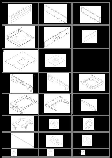
74 75
75 No. Discription Part number Material Piece/assembly 1 Cabinet side panel Wood 2 Cabinet bracket left Steel galvanised DC01 ZE25/25 1x 3 Cabinet bracket right Steel galvanised DC01 ZE25/25 1x 4 Cabinet base Aluminium anodized 1x 5 Front (pre-assembled) , Aluminium, anodized 6 Display window Bleu acrylic (PMMA) 1x 7 Top cover Aluminium anodized 1x 8 Hatch Aluminium anodized 1x 9 Carrier support bracket left Steel galvanised DC01 ZE25/25 1x 10 Carrier support bracket right Steel galvanised DC01 ZE25/25 1x 11 Drive cover Stainless steel x 12 Carrier Stainless steel x 13 Leaver Stainless steel x 1x left 1x right 14 Leaver Stainless steel x L, 1xR 15 Hatch support Stainless steel x 16 Slide bearing (pre-assembled) CuSnPb 2x 17 Fast lock washer (pre-assembled) Spring steel 2x 18 Shaft Cr V x 19 Glide POM 2x 20 Positional bracket Steel galvanised DC01 ZE25/25 1x 21 Philips screw M3x4 Steel galvanized 14x 22 Pivot washer Glass fibre filled PA6 10x 23 Socket set screw M3x4 Steel blackened 3x 1x 76
Prusa i3 Printer Assembly Guide
 Prusa i3 Printer Assembly Guide Special thanks to Carlos Sanchez and Miguel Sanchez for the graphics. All graphics captured from their great animation: http://www.carlos-sanchez.com/ Prusa3/ For copyright
PSL2 Assembly guide. PSL2 Assembly guide. Resistors. Test pins. Document revision 1.1 Last modification : 30/05/08
 Safety warning THIS KIT IS NOT FOR BEGINNERS! This kit is main powered and use potentially lethal voltages. Under no circumstance should someone undertake the realisation of this kit unless he has full
DCX2496 Linear Power Supply mod by
 DCX2496 Linear Power Supply mod by Construction Guide Linear Power Supply for the DCX2496 Introduction. One of my more rewarding modifications to the DCX2496 was the replacement of the stock I/O board
(2 DPDT 2 4 X
 Dynaco ST-120 with VTA driver board Kit instruction manual Triode/Pentode version Congratulations on your purchase of the Dynaco ST-120 with VTA driver board kit. Every effort has been made to give you
3D PRINTER. Pack 09. Anything you can imagine, you can make! 3D technology is now available for you at home! BUILD YOUR OWN
 BUILD YOUR OWN Pack 09 Anything you can imagine, you can make! 3D PRINTER Compatible with Windows 7 & 8 Mac OS X 3D technology is now available for you at home! www.model-space.com BUILD YOUR OWN 3D PRINTER
WIRING THE HEATER POWER SUPPLY
 WIRING THE HEATER POWER SUPPLY Fig. 14 13/14 Take the longer PS board (with the 47R resistors and the fuse) and, using M3x6 screws, fix it to the chassis to the left of the mains transformer. The diodes
Kit1 300B Edition. Single Ended Triode 8 Watt. Construction Manual & User Guide Volume One
 Kit1 300B 2014 Edition Single Ended Triode 8 Watt Construction Manual & User Guide Volume One Contents Section 1: Receiving your kit...2 Section 2: The Mechanical section Preparation... 3 Tang Strips...
Simple Eurorack Row. Kit Builder's Guide. 4mspedals.com
 Simple Eurorack Row Kit Builder's Guide 4mspedals.com ' Simple Eurorack Row This guide is for building a single-row eurorack case with a power supply. When completed, the case is ready to accept eurorack
Bag 1. Bag 1. Center Pivot. Center Pivot
 8 00734 01901 5 Center Pivot Bag 1 3374 - Center Pivot Socket 4019 - Alum Pivot ball 3254-2-56 Button Head *Note - Sometimes it is helpful to slightly over-tighten the top clamp screws, then work the ball
Connecting the rear fog light on the A4 Jetta, while keeping the 5 Light Mod
 Connecting the rear fog light on the A4 Jetta, while keeping the 5 Light Mod DISCLAIMER: I'm human and make mistakes. If you spot one in this how to, tell me and I'll fix it This was done on my 99.5 Jetta.
Installation Manual TWM Performance Short Shifter Cobalt SS/SC, SS/TC, HHR SS, Ion Redline and Saab 9-3
 Page 1 Installation Manual TWM Performance Short Shifter Cobalt SS/SC, SS/TC, HHR SS, Ion Redline and Saab 9-3 Please Note: It is preferable to park on a flat surface, as you will have to engage and disengage
Build Instructions and User Guide
 Build Instructions and User Guide Getting Started To build the Rock Drill 4069 you will need: Solder Wire Cutters Soldering Iron Small pliers The kit is suitable for beginners or more experienced builders
Installation Instructions Table of Contents
 Installation Instructions Table of Contents Pre- Installation of Garage Storage Lift 2 Layout the Garage Storage Lift 3 Installing the strut Channels 3 Install the Drive Assembly 5 Install the Drive Shaft
Contents. Preparing the motor Winding the rotating secondary Winding the primary... 8
 120732-130389 Propeller Clock Construction Notes Revision E, December 2, 2013 Contents Preparing the motor... 2 Winding the rotating secondary... 5 Winding the primary... 8 UltiProp Clock (Elektor Dec.
FlexJet Carriage Circuit Board (PCB) Replacement
 Replacement") P/N: 111484 R0 14140 NE 200th St. Woodinville, WA. 98072 PH: (425) 398-8282 FX: (425) 398-8383 ioline.com FlexJet Carriage Circuit Board (PCB) Replacement Notices: Warning! Ensure that all AC power cables
P/N: 111484 R0 14140 NE 200th St. Woodinville, WA. 98072 PH: (425) 398-8282 FX: (425) 398-8383 ioline.com FlexJet Carriage Circuit Board (PCB) Replacement Notices: Warning! Ensure that all AC power cables
Modix Big-60 Assembly Manual Part 2
 Modix Big-60 Assembly Manual Part 2 Version 1.0, October 2017 Menu 1. Motors & End Stop Wiring... 3 2. Controller Wiring Check... 6 3. Extruder Wiring... 7 4. Electronic Box Cover... 9 5. Filament Sensor...
FlexJet - Flex Cable Replacement
 P/N: 109515R0 14140 NE 200th St. Woodinville, WA. 98072 PH: (425) 398-8282 FX: (425) 398-8383 FlexJet - Flex Cable Replacement Notices: Warning! Ensure that all AC power cables are removed from the printer
BMW E61 Hydraulic Pump replacement instructions
 BMW E61 Hydraulic Pump replacement instructions This DIY will guide you through the tasks needed to successfully replace your defective tailgate hydraulic pump Difficulty 3 of 10. The most difficult part
Mableaudio Company limited
 Mableaudio Company limited Web: www.mableaudio.com [5E3 assembly manual] Tel:0086-755-83996326 fax:0086-755-83996326 Contact: Ms Mable mable@mableaudio.com WARNING! This amp operates at voltages that may
Remove the 3-11mm nuts holding mirror on. Don t drop the nuts!
 2005-2012 Ford Mustang Puddle Lamp Kit Parts List: Quantity: Tool List: LED Lamps 2 Flat head screwdriver Seals 2 Ratchet & Socket set OR Nuts 2 Adjustable Wrench Wiring harness 1 Drill & 11/16 th bit
FITTING THE RELAY SWITCH BOARD FITTING THE INPUT SELECTOR SWITCH
 FITTING THE RELAY SWITCH BOARD Fit M3 x 12mm spacers to the COMPONENT side of the board. Use fibre washers under M3 screws on the SOLDER side of the board to avoid grounding the tracks. Push the completed
Stand Alone Fog Lights Installation Instructions
 Tools Required: 1. Trim Removal tool or protected flat screwdriver 2. #2 Phillips Screwdriver 3. 10mm socket 4. 10mm wrench 5. 8mm or 5/16 socket 6. Adjustable Pliers 7. Electrical Tape WARNING!!! Disconnect
BLUE LIGHT FOR DYNACO STEREO 120, SCA-80, OR PAT-4 ROCKER SWITCHES
 BLUE LIGHT FOR DYNACO STEREO 120, SCA-80, OR PAT-4 ROCKER SWITCHES 2014 AkitikA, LLC All rights reserved Revision 1p5 April 8, 2014 Page 1 of 16 Table of Contents Table of Contents... 2 Table of Figures...
Installation instructions for Alpha Racing Quickshifter/Blipper for a pre-2014 S1000RR
 Skill Level: Intermediate Installation instructions for Alpha Racing Quickshifter/Blipper for a pre-2014 S1000RR Tools Required: Alen keys/socket/drivers Torx keys/sockets/drivers Metric box wrenches and
BehringerMods.com. Instructions for modification of Behringer DCX analog inputs and outputs
 BehringerMods.com Instructions for modification of Behringer DCX analog inputs and outputs The following instructions will cover the details of fully modifying a unit with analog output and analog input
Assembly Manual. 1/10th Formula 1 Car
 Assembly Manual 1/10th Formula 1 Car Center Pivot Bag 1 3374 - Center Pivot Socket 40194 - Hard Anodized Alum Pivot ball 3254-2-56 *Note - Sometimes it is helpful to slightly over-tighten the top clamp
Desktop 5.5 Z Axis Retrofit
 Page 1 Kit parts Desktop 5.5 Z Axis Retrofit Carriage plate with stop bolt and Z proximity switch installed Zip ties Spare bolts Spindle mounting plate with stop bolt, spring mount, and rail Z proximity
Kodak 750H Carousel Projector Repair
 Kodak 750H Carousel Projector Repair An AT YOUR OWN RISK PROJECT by Klaus Wolter, Rev B, 3-26-2016 Here I documen the repair of my 750H carousel. A common problem with this projector, and all of the projectors
Sunroof Repair. Sunroof Repair TSB. The sunroof repair kit available for the J30 is part number Y20. See images at bottom of document.
 Sunroof Repair This document is the text/images from the TSB (technical service bulletin) issued by Infiniti concerning the repair procedure for sunroof issues. Be advised that this is a LARGE, TIME-CONSUMING
Assembly Manual. 1/10th World GT car
 Assembly Manual 1/10th World GT car Center Pivot Bag 1 3374 - Center Pivot Socket 40194 - Hard Anodized Alum Pivot ball 3254-2-56 Button Head *Note - Sometimes it is helpful to slightly over-tighten the
Replacing MK4 Golf/Jetta radiator mounts in-car
 Replacing MK4 Golf/Jetta radiator mounts in-car This is a guide to replacing the radiator mounts in a MK4 Golf/Jetta. This involves moving the core support to the service position which allows you to do
VECTRIX VX-2 SERVICE MANUAL. Version 1.0/May 2011 VECTRIX, LLC
 www.vectrix.com CONTENTS SECTION A: Tools 1 Tools Needed SECTION B: Mechanical Parts 1 Front Fairing 2 Front Console Cover 3 Speedometer Cover 4 Front Vertical Panel Cover-Lower 5 Front Vertical Panel
Lab 4: Robot Assembly
 E11: Autonomous Vehicles Lab 4: Robot Assembly In this lab, you ll put together your very own robot! You should have a Mudduino and a chassis, as well as your kit of parts. Now it s time to put them all
C15C C15C. Page 1 of 20
 2 x Lid Front Hinge 1135 8 x M8 Bolt 8 x M8 Washer (3mm Thick) 4 x M6 Large washers 4 x M6 Spring washers 4 x M6 x 40mm Bolts 6 x M6 20mm Bolts 6 x M6 Washers 20 x Screws 2 x Lid mount gas strut bracket
Ford Racing BOSS 302 Engine Oil Cooler (11-14 GT)
") Tools needed: 14mm hex socket 7mm socket/wrench 8mm socket/wrench Ford Racing BOSS 302 Engine Oil Cooler (11-14 GT) 10mm socket (for airbox removal) ¾ inch or 19mm wrench Torque wrench Appropriate ratchets
Tools needed: 14mm hex socket 7mm socket/wrench 8mm socket/wrench Ford Racing BOSS 302 Engine Oil Cooler (11-14 GT) 10mm socket (for airbox removal) ¾ inch or 19mm wrench Torque wrench Appropriate ratchets
These instructions show how to build the Remote Controlled Fart machine Sound Kit.
 Remote Controlled Fart Machine Assembly Instructions These instructions show how to build the Remote Controlled Fart machine Sound Kit. Tools Required Drill with 7/64, 3/16, and ¼ drill bits. Holt melt
Installation instructions, accessories - Rear Seat Entertainment
 XC90 Section Group Weight(Kg/Pounds) Year Month 3 39 2004 10 XC90 2003, XC90 2004, XC90 2005, XC90 2006, XC90 2007, XC90 2008 Replaces issue: 2003 12 J3904620 Page 1 of 18 Required tools A0000162 A0000163
Page1. ISF Stainless Steel Headers // Part# HDR-004
 Congratulations on the purchase of your ISF Stainless Steel Headers and thank you for choosing Sikky Manufacturing. This installation manual is intended to guide you through the removal of the factory
Thank you for purchasing a kit from SparKIT. Your support is greatly appreciated.
 SparKIT Instructions Thank you for purchasing a kit from SparKIT. Your support is greatly appreciated. First of all we would like to go through a few basic precautions. 1. This kit includes small parts
BLUE LIGHT FOR DYNACO STEREO 120 OR PAT-4 ROCKER SWITCHES
 BLUE LIGHT FOR DYNACO STEREO 120 OR PAT-4 ROCKER SWITCHES 2012 AkitikA, LLC All rights reserved Revision 1p3 April 18, 2012 Page 1 of 15 Table of Contents Table of Contents... 2 Table of Figures... 2 Section
Arlo Power Distribution Board Kit Rev B (#28996)
") Web Site: www.parallax.com Forums: forums.parallax.com Sales: sales@parallax.com Technical: support@parallax.com Office: (916) 624-8333 Fax: (916) 624-8003 Sales: (888) 512-1024 Tech Support: (888) 997-8267
Web Site: www.parallax.com Forums: forums.parallax.com Sales: sales@parallax.com Technical: support@parallax.com Office: (916) 624-8333 Fax: (916) 624-8003 Sales: (888) 512-1024 Tech Support: (888) 997-8267
Automatic Roof Hatch Opener
 Automatic Roof Hatch Opener Installation Guide REQUIRED TOOLS (These tools are required to complete the installation) Cordless Drill 1/8 1/4 Drill Bits 1/8 Pin Punch #2 Philips Bit Rachet Sharpie Hammer
Upgrade v3 to v3.2. SeeMeCNC Guides. Upgrade v3 to v3.2. Rostock Max v3 Uprgade to v3.2. Written By: SeeMeCNC seemecnc.dozuki.
 SeeMeCNC Guides Upgrade v3 to v3.2 Rostock Max v3 Uprgade to v3.2 Written By: SeeMeCNC 2018 seemecnc.dozuki.com/ Page 1 of 34 INTRODUCTION This guide is intended to Upgrade a Rostock Max v3 to a Rostock
Bachmann GWR Earl (Dukedog) EM Finescale Conversion
 EM Finescale Conversion") Bachmann GWR Earl (Dukedog) EM Finescale Conversion Before you start, it is a good idea to have some small containers or snap top poly bags to put screws and components in for safe keeping...much better
Bachmann GWR Earl (Dukedog) EM Finescale Conversion Before you start, it is a good idea to have some small containers or snap top poly bags to put screws and components in for safe keeping...much better
Mustang CDC Lightbar (94-04) - Installation Instructions
 - Installation Instructions") Mustang CDC Lightbar (94-04) - Installation Instructions The below installation instructions work for the following products: Classic Design Concepts Mustang Convertible Lightbar (94-04 Carbon Fiber) Classic
Mustang CDC Lightbar (94-04) - Installation Instructions The below installation instructions work for the following products: Classic Design Concepts Mustang Convertible Lightbar (94-04 Carbon Fiber) Classic
CHROME ALLEY CAT L.E.D. FUEL & BATTERY GAUGE 7381
 CHROME ALLEY CAT L.E.D. FUEL & BATTERY GAUGE 7381 Thank You For Choosing Küryakyn! Protect yourself and others from potential injury and property damage or loss. Pay close attention to all instructions,
ARDUINO 2WD SMART ROBOT CAR KIT
 EN ARDUINO 2WD SMART ROBOT CAR KIT P a g e 2 PARTS LIST Please make sure that the following pieces are included in your kit Component Quantity Remarks Arduino Sensor Shield v5.0 1 Align pins using needle
2005 and 09 Mustang install instructions Sequential / Chase Unit Partial Plug-N-Play Kit Meter4it Eng. Updated: 3/28/09
 Updated: 3/28/09 Verify content of kit: 1- Unit with wiring harness 1- Red power wire with 15 amp fuse 1- Color instruction 2- Velcro for mounting 1-Driver taillight harness 1- Passenger taillight harness
PRODUCT MANUAL Gecko Wireless One Zone LED Dimmer and Receiver
 Product Description The Gecko Wireless One Zone Wall LED Dimmer has been designed to bring light control easily. No wires or switch box locations are needed, just stick or mount the Gecko to any flat location
Troubleshooting Guide for Okin Systems
 Troubleshooting Guide for Okin Systems More lift chair manufacturers use the Okin electronics system than any other system today, mainly because they re quiet running and usually very dependable. There
Arlo Power Distribution Board Kit Rev B (#28996)
") Web Site: www.parallax.com Forums: forums.parallax.com Sales: sales@parallax.com Technical: support@parallax.com Office: (916) 624-8333 Fax: (916) 624-8003 Sales: (888) 512-1024 Tech Support: (888) 997-8267
Web Site: www.parallax.com Forums: forums.parallax.com Sales: sales@parallax.com Technical: support@parallax.com Office: (916) 624-8333 Fax: (916) 624-8003 Sales: (888) 512-1024 Tech Support: (888) 997-8267
DIY Bi-Metallic Strip
 DIY Bi-Metallic Strip An introduction to the applications of thermal expansion and two-way switching. Written By: Mahaaveer BN 2018 Page 1 of 14 INTRODUCTION A bi-metallic strip is used to convert a temperature
DIY Synth Kit - Manual STUTTER SYNTH
 DIY Synth Kit - Manual STUTTER SYNTH Welcome to the DIY Synth - Manual This is a step-by-step guide to making your own electronic Synth. All you will need is your hands and your DIY Synth kit which includes
INSTALLATION INSTRUCTIONS
 COLD AIR INTAKE INSTALLATION INSTRUCTIONS PART NUMBER D760-0390C APPLICATION: 1999-2003 E39 M5 PARTS LIST 1 Left Aluminum Intake Tube 1 Air Pump Bracket (A) 1 Right Aluminum Intake Tube 1 Air Pump Bracket
Fanatec GT3RS V1 to GT3RS V2 Tutorial
 Fanatec GT3RS V1 to GT3RS V2 Tutorial by Roy Visser 1 How to update your Fanatec GT3RS V1 wheel to a GT3RS V2 wheel Welcome to this guided and detailed tutorial for upgrading your Fanatec GT3RS V1 wheel
Tip: and Orient Express LED Light Upgrade Date: Correction
 Hi All, I have since inherited my friend Rudolf s 42755 Orient Express with the extra 42760 car set and wanted to complete the LED light upgrade as we had planned. Side view of the Restaurant car with
Rollstar Shade Installation Instructions
 Rollstar Shade Installation Instructions All Lifting Systems Inside or Outside Mount Thank you for purchasing your new Rollstar shade. It has been custom-made from the highest quality materials to the
Uno Compatible Pogobed Kit
 Uno Compatible Pogobed Kit Intermediate Level The pogobed kit is a hardware fixture that enables you to temporarily connect from your Arduino development board to any Arduino shield. Using the springloaded
BROOKS STAIRLIFTS SUPERGLIDE 120
 BROOKS STAIRLIFTS SUPERGLIDE 120 INSTALLATION PROCEDURES CONTENTS Health And Safety Hazards 3 Unpacking the Stairlift Carriage 4 Pre-Installation Procedure 5 Box Contents 6 Installation Tools 9 1.1 Required
Detroit Speed, Inc. Electric Headlight Door Kit Corvette P/N: &
 Detroit Speed, Inc. Electric Headlight Door Kit 1968-82 Corvette P/N: 122006 & 122007 The Detroit Speed Inc. Electric Headlight Door Kit replaces the stock vacuum actuated system on all 1968-82 Corvettes.
Go-ped ESR750 / ESR750EX Rear Brake Installation Instructions
 Go-ped ESR750 / ESR750EX Rear Brake Installation Instructions This kit provides all the parts you need to install a rear brake on your ESR750 or ESR750EX. It will not work on an ESR Sport, or other Go-ped
FITTING OIL TEMP AND PRESSURE GUAGES
 FITTING OIL TEMP AND PRESSURE GUAGES this guide is of reference to fitting an oil temp and pressure sender/ sensor into a sandwich plate- not the sump plug temp sensor (although it wouldn't be much different
Notice Regarding this Upgrade. WARNING! Danger Potential
 Notice Regarding this Upgrade WARNING! Danger Potential Although this kit has been designed to be easy-to-install, and has been tested in many installations; caution must be exercised when installing this
SPACESAVER EC-300 A ELECTRICS
 INSTALLATION INSTRUCTIONS SPACESAVER EC-300 A ELECTRICS SECTION I TOP MOUNTED ELECTRICS SECTION II FACE PANEL MOUNTED ELECTRICS SECTION III ZFS INSTALLATION INSTRUCTIONS This symbol indicates a connection
RS-2 SINGLE ACTION REAR BUMPER WITH TIRE CARRIER INSTALL MANUAL FOR JEEP WRANGLER ALL MODELS.
 RS-2 SINGLE ACTION REAR BUMPER WITH TIRE CARRIER INSTALL MANUAL FOR 2007-2016 JEEP WRANGLER ALL MODELS. Rear Bumper Installation Instructions 1) Remove factory rear bumper, (this includes all tow hitch
Depress each tab as you pull the bezel off. The bezels are tight. L.H. shown.
 2013-2014 Ford Mustang V6 & Boss 302 Lower Valance Fog Light Kit Parts List: Quantity: Tool List: Fog light & bulb with bracket 2 Flat head & Phillips screwdriver Black bezels 2 Ratchet & Socket set OR
5X Racing Mazda Miata Aluminum Shifter Bushing Installation Instructions
 5X Racing Mazda Miata Aluminum Shifter Bushing Installation Instructions Thank you for your purchase! These instructions will explain how to properly install a 5X Racing Aluminum Shifter Bushing in your
DMR 3005 WM ONE ZONE WIRELESS DIMMER RECEIVER
 E363518 DMR 3005 WM ONE ZONE WIRELESS DIMMER RECEIVER 20725 NE. 16 AVE. #A-33 MIAMI, FLORIDA 33179 Tel: (305) 652-2599 Fax: (305) 650-8812 www.lumiron.com Email: sales@lumiron.com 1 Benefits and Features
MAX FLOW FUEL KIT KIA FORTE SX HYUNDAI VELOSTER TURBO INSTALLATION INSTRUCTIONS
 MAX FLOW FUEL KIT KIA FORTE SX 2014+ HYUNDAI VELOSTER TURBO INSTALLATION INSTRUCTIONS Installation: Tools needed: 1/4 or 3/8 drive ratchet Different length extensions 8mm socket / 10mm socket / 12mm socket
Lakela nd H2 Low Speed Stator Coil Installation
 Lakela nd H2 Low Speed Stator Coil Installation Step 1: Place the stator assembly on a padded surface to protect the plastic signal generators, and orient it as shown in figure 1. The low speed coil is
Biasing the Vintage Series (Nomad, BelAir, VT50, Vintage 33)
") Biasing the Vintage Series (Nomad, BelAir, VT50, Vintage 33) This chapter will outline and guide you through the procedures of biasing the Vintage series amplifier. The procedures are broken down in a
Biasing the Vintage Series (Nomad, BelAir, VT50, Vintage 33) This chapter will outline and guide you through the procedures of biasing the Vintage series amplifier. The procedures are broken down in a
Australia s best value ebikes
 IMPORTANT NOTICE Read manual, Instructions and Terms carefully before use. It is the buyer s responsibility to make sure the drift trike is safe to ride. If necessary ask for help at any good local bicycle
5. E-axis assembly. 5. E-axis assembly. Written By: Jakub Dolezal manual.prusa3d.com/ Page 1 of 40
 5. E-axis assembly Written By: Jakub Dolezal 2018 manual.prusa3d.com/ Page 1 of 40 Step 1 Tools necessary for this chapter Needle-nose pliers for zip tie trimming. 2.5mm Allen key for M3 screws 2mm Allen
X.L. BAND W/ SPRING ASSIST INSTRUCTION MANUAL
 PARTS LIST X.L. BAND W/ SPRING ASSIST INSTRUCTION MANUAL (2) Bands (1) Handle assembly (2) Side hinge assemblies (1) Left rear hinge assembly (1) Right rear hinge assembly (2) front spring s (2) rear spring
Bill Conkling July 2012
 Bill Conkling July 2012 Introduction: For any ham, there are moments that are priceless, like snagging that elusive rare DX station on a deserted island that hasn t been activated in 52 years. And certainly,
Installation Tips for your Crimestopper/ProStart Remote Start system (add-on for GM vehicles) v1.02 updated 1/16/2013
 v1.02 updated 1/16/2013") Installation Tips for your Crimestopper/ProStart Remote Start system (add-on for GM vehicles) v1.02 updated 1/16/2013 Thank you for purchasing your remote start from MyPushcart.com - an industry leader
Installation Tips for your Crimestopper/ProStart Remote Start system (add-on for GM vehicles) v1.02 updated 1/16/2013 Thank you for purchasing your remote start from MyPushcart.com - an industry leader
SMITHS CAR CLOCK REPAIR KIT
 SMITHS CAR CLOCK REPAIR KIT Version 9 1 Introduction These instructions explain how to repair a Smith s electric car clock mechanism using the Clocks4Classics repair kit. This kit uses a specially developed
Chapter 2. Battery Charger and Base Assembly
 Chapter 2 Battery Charger and Base Assembly 11 CHAPTER 2. BATTERY CHARGER AND BASE ASSEMBLY 2.1 Section Overview This Lab teaches students how to assemble a Tekbot, in the following steps: Describe the
MONGOOSE. Introduction. < blueroomelectronics > Assembly Instructions. Mongoose was designed as an introduction to Mechatronics.
 MONGOOSE Assembly Instructions Introduction Mongoose was designed as an introduction to Mechatronics Page 1 of 12 Before you start The Mongoose is a complex kit and skipping instructions is not advised,
Switchback Carrier Rack System
 Switchback Carrier Rack System Installation Instructions 1 Rocky Mountain Westy Ph. (970)310-3441 Introduction Thank you for purchasing the Rocky Mountain Westy Switchback Carrier Rack System. We pride
Troubleshooting Guide for Limoss Systems
 Troubleshooting Guide for Limoss Systems NOTE: Limoss is a manufacturer and importer of linear actuators (motors) hand controls, power supplies, and cables for motion furniture. They are quickly becoming
FiveFish Studios PSU-2448Plus+ Assembly Guide
 FiveFish Studios PSU-2448Plus+ Assembly Guide Copyright 2015-2017 FiveFish Audio Revision 1.02-20171105 No part of this document may be reproduced, either mechanically or electronically, posted online
LPE C5 Battery Relocation Kit
 LPE C5 Battery Relocation Kit The LPE C5 Corvette battery relocation kit improves vehicle weight distribution by moving weight to the rear of the vehicle. The improved weight distribution increases traction
3143 Production Drive Fairfeild, Ohio Model HA Installation and Service Manual
 3143 Production Drive Fairfeild, Ohio 45014 513-874-3733 Model HA-1000 Installation and Service Manual 3143 Production Drive Fairfeild, Ohio 45014 513-874-3733 Model HA-1000 Installation and Service Manual
PAT-4 TOROIDAL TRANSFORMER ASSEMBLY MANUAL
 PAT-4 TOROIDAL TRANSFORMER ASSEMBLY MANUAL 2015 AkitikA, LLC All rights reserved Revision 1p3 August 22, 2015 Page 1 of 13 Table of Contents Table of Contents... 2 Table of Figures... 2 Section 1: About
BeetleBot. The Simple Zippy Screw-Together Robot Kit! SKU: K JB. jb/
 BeetleBot The Simple Zippy Screw-Together Robot Kit! www.solarbotics.com 1-866-276-2687 SKU: K JB http://www.solarbotics.com/products/k_ jb/ Document Revision: January 05 2016 Shell Board 2 x Sensor Wires
Stirling Engine. What to Learn: A Stirling engine shows us how energy is converted and used to do work for us. Materials
 Stirling Engine Overview: The Stirling heat engine is very different from the engine in your car. When Robert Stirling invented the first Stirling engine in 1816, he thought it would be much more efficient
JL SHIELD TIRE CARRIER INSTALLATION INSTRUCTIONS
 JL SHIELD TIRE CARRIER INSTALLATION INSTRUCTIONS TOOLS NEEDED 3/4 Wrench 3/4 Socket 9/16 Wrench or Socket 1 1/2 Socket 1 1/8 Wrench 13mm Socket Torque Wrench for 1 1/2 Socket HARDWARE 2-1/2 X 2 Hex Bolt
2010 Toyota Prius Fog Light Retrofit
 2010 Toyota Prius Fog Light Retrofit A DIY prospective Last updated: Friday, December 25, 2009 *** Disclaimer Use this document and its contents at your own risk! *** Forward: This document was compiled
Eibach Pro-System-Plus
 Eibach Pro-System-Plus Tools : - Floor Jack - 3 Jack Stands (4 preferred) - 2 wheel stoppers - Car wrench set - Fire torch - Bolt thread locker (use on every bolt you tight) Disclaimer: This guide is not
Service Manual Mozart Fireplace
 Service Manual Mozart Fireplace Model Numbers: CFP3913 REV PCN DATE 00 11637 Sep 23, 09 Dimplex North America Limited 1367 Industrial Road Cambridge ON Canada N1R 7G8 1-888-346-7539 www.dimplex.com In
PORSCHE V r Valve Timing Instructions. Copyright 2009 Written by Mike Frye Edited my Adam G.
 PORSCHE 928 32V r Valve Timing Instructions Copyright 2009 Written by Mike Frye Edited my Adam G. Sections: Overview.3 Disclaimer/warnings/things to watch for 4 Terms and naming conventions used in this
This LED flashtube kit covers models 400, 404, 500, 504, 600, 680 & 506.
 L.E.D. INSTRUCTIONS I D T S O T U B I R M O C R Y N A P Kit contains: This LED flashtube kit covers models 400, 404, 500, 504, 600, 680 & 506. For the power supply: 1-LED power supply circuit board, 2
Toyota Tacoma Winch Mount Bumper Installation Instructions Tools Required: Transmission cooler relocation brackets Torque Wrench
 2016-2017 Toyota Tacoma Winch Mount Bumper Installation Instructions Tools Required: Items Included: Small flat head screw driver Winch Mount Ratchet, 10mm, 12mm, 14mm, 17mm & Skid Plate 19mm sockets Transmission
Installation Tips for your Remote Start/Keyless Entry (for Honda/Acura Vehicles) [EVO-ALL] v1.02 updated 9/13/2013
![Installation Tips for your Remote Start/Keyless Entry (for Honda/Acura Vehicles) [EVO-ALL] v1.02 updated 9/13/2013](/thumbs/87/96035180.jpg "Installation Tips for your Remote Start/Keyless Entry (for Honda/Acura Vehicles) [EVO-ALL] v1.02 updated 9/13/2013") Installation Tips for your Remote Start/Keyless Entry (for Honda/Acura Vehicles) [EVO-ALL] v1.02 updated 9/13/2013 Thank you for purchasing your remote start from MyPushcart.com - an industry leader in
Installation Tips for your Remote Start/Keyless Entry (for Honda/Acura Vehicles) [EVO-ALL] v1.02 updated 9/13/2013 Thank you for purchasing your remote start from MyPushcart.com - an industry leader in
IV-3 VFD Shield for Arduino. Assembly Manual
 June 2014 Table of Contents 1 Overview Features Applications 3 3 3 2 Assembly Hints 4 3 PCB Overview 5 4 Circuit Diagram 6 5 Assembly Diodes and IC socket Electrolytic capacitors Ceramic capacitors 10K
Procharger Stage II Intercooled Supercharger System (11-14 GT)
") Procharger Stage II Intercooled Supercharger System (11-14 GT) Installation Time: Approximately one day. Installed on 2012 Mustang GT 5.0/Manual Required Tools 3/8 Socket Set (Standard and Metric) 1/2
Procharger Stage II Intercooled Supercharger System (11-14 GT) Installation Time: Approximately one day. Installed on 2012 Mustang GT 5.0/Manual Required Tools 3/8 Socket Set (Standard and Metric) 1/2
Adjusting Carbs For Re-Jetting (Procedure written for an Intruder 1500 LC) NEWLY UPDATED: APRIL 2003
 NEWLY UPDATED: APRIL 2003") SECTION ONE: Get Prepared - Tools Adjusting Carbs For Re-Jetting (Procedure written for an Intruder 1500 LC) NEWLY UPDATED: APRIL 2003 Courtesy of: Half-Crazy Get a manual impact driver (the kind you hit
SECTION ONE: Get Prepared - Tools Adjusting Carbs For Re-Jetting (Procedure written for an Intruder 1500 LC) NEWLY UPDATED: APRIL 2003 Courtesy of: Half-Crazy Get a manual impact driver (the kind you hit
Installation Manual TWM Performance Short Shifter Subaru STi 2008+
 - 1 - Installation Manual TWM Performance Short Shifter Subaru STi 2008+ Please Note: It is preferable to park on a flat surface, as you will have to engage and disengage the hand brake and shift from
Ford Mustang V6 OEM-Style Fog Light Kit Parts List: Quantity: Tool List:
 2015-2017 Ford Mustang V6 OEM-Style Fog Light Kit Parts List: Quantity: Tool List: LED Foglights/ Bezels 2 Flat head & Phillips screwdriver (if you ordered part#3600) Ratchet & Socket set OR Wiring harness