MONGOOSE. Introduction. < blueroomelectronics > Assembly Instructions. Mongoose was designed as an introduction to Mechatronics.
|
|
|
- Evan Quinn
- 5 years ago
- Views:
Transcription

1 MONGOOSE Assembly Instructions Introduction Mongoose was designed as an introduction to Mechatronics Page 1 of 12


2 Before you start The Mongoose is a complex kit and skipping instructions is not advised, the method below is the quickest and easiest method we could find. If you take your time the kit will provide you with a reliable, durable and fun robot chassis for your experiments. The main stages of assembly are mechanical, electrical and electronic. An x2 means you have to repeat this step twice for both the left and right halves. The Mongoose contains many small parts and it s advisable to keep any loose parts in a tray to prevent loss. MECHANICAL Chassis PreAssembly Modifing the gearbox frame The center frame piece must me modified before assembly. The front opening on both sides must be enlarged towards the center as shown in RED by approximately 5mm and is easily accomplished by carefully trimming the plastic with a small modeling knife or filing the material away. This makes room for the optical sensors. Apply foam spacers to the gearbox x2 Apply a self-adhesive foam spacer to both left and right gearbox halves. Apply optical interrupters to two encoder gears x2 Two of the BLUE gears require the addition of self-adhesive foil illustrated in RED to act as light blockers for the optical sensors. With a sharp x-acto knife carefully trim the excess foil along the shown with the GREEN line. The foil blocks IR light from the normally transparent to IR gears. Page 2 of 12
 Thread a small silver grub screw into a brass hex hub.")

3 Assembling the axles x2 Short 28mm axle (round) Press fit the long yellow bushing as shown in the image. Hint: the small brass bushings are 4mm Long 50mm axle (hex) Thread a small silver grub screw into a brass hex hub. Slide the hub assembly over the hex axle and tighten (very tight) at 29mm from one end of the axle. Hint: An easier method than measuring is to preassemble the long axle. From right to left you need a brass spacer, silver collar, blue gear then yellow drive gear. When the brass bushing is flush with the end of the axle tighten the grub screw with the small Allen wrench included with the Mongoose kit. Installing the motor pinion gear x2 On a flat surface simply press a small purple pinion gear on to each motor as shown, do not press on the motor but instead apply gradual pressure to the motor shaft. Attach metal chassis sides to gearbox halves x2 Using a 10mm screw mount as shown, do not tighten yet. Using a single 10mm screw mount as shown, do not tighten yet. This short screw Page 3 of 12
4 ELECTRICAL The motor wiring harness x2 There are two sets of blue & yellow #22guage wire, they are approximately 13cm long with 12cm of insulation, 2mm of insulation is removed at the connector end and 8mm at the motor end. Each motor requires one large 0.1uf noise suppression capacitor, be careful not to mount the capacitor too close to the motor as it will be difficult to slide to motor into the gearbox later in assembly. A simple method is to line the top of the cap with the front of the motor housing. Now insert the 10mm bare end of the blue and yellow wires with the capacitor as shown below. Carefully solder the capacitor and wires to the motor terminals. With you wire cutters clip off the excess wire and capacitor leads. Make sure you put the blue and yellow wires on as shown; else your motors will run backwards. You can crimp the connector terminals to the 2mm bare end of the both wires. Hint if you are good at soldering; a very small dab of solder to the crimp terminal after crimping will improve the reliability of the harness. Page 4 of 12

5 Page 5 of 12
 Needle nose pliers (small) Slotted screwdriver (small) Phillips screwdriver (#1) Multimeter (Ohms, Volts) Assembly Final Assembly Initial Testing Page 6 of 12")
6 ELECTRONIC Necessary Tools (not included in kit) As with any electronic kit the following tools are essential: Low wattage fine tip soldering iron <50W Resin core solder Wire cutters or side cutters (small) Needle nose pliers (small) Slotted screwdriver (small) Phillips screwdriver (#1) Multimeter (Ohms, Volts) Assembly Final Assembly Initial Testing Page 6 of 12
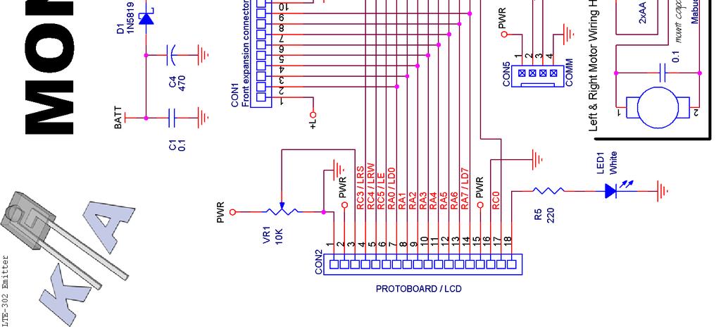
7 Parts List Mongoose Controller Board Capacitors C1,C2,C3 0.1uf Small Monolithic Capacitor C4,C5 470uf Electrolytic 6.3V Resistors ¼W 5% Carbon (tan body, 4 color bands) R1,R5 220 Red, Red, Brown, Gold R2,R3 4.7K Yellow, Violet, Red, Gold R4 10K Brown, Black, Orange, Gold VR1 10K Variable Resistor (Horizontal) Semiconductors D1 1N5817 Schottky Diode D2 1N4148 Switching Diode IR1,IR2 LTE-302 IR Emitter Q1,Q2 LTE-301 IR Detector U1 PIC18F2525 Microcontroller U2 SN Quad Half Bridge with internal diodes Connectors CON1 10 pin inline female connector CON2 20 pin R/A inline female connector CON3 2x5 R/A header CON4,6 4 pin Molex KK male connector CON3 2x5 R/A header 2x Spacers for Opto-Coupler pair Miscellaneous J1 Ferrite Bead 2x AA Battery Holder 1x 28pin Socket 1x 16pin Socket Motors Cx,Cx 0.1uf Large Green Motor Noise Suppressors Page 7 of 12

8 Page 8 of 12

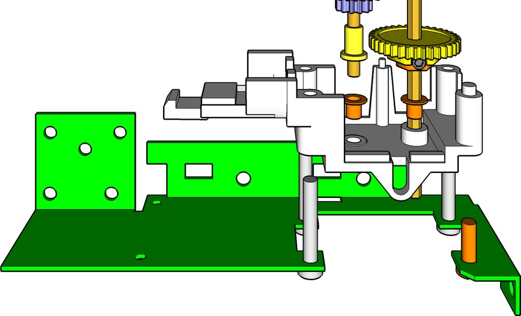
9 Mongoose Gearbox Drive Train The Page 9 of 12
. They are located on the gearbox and rotate 27x faster than the drive wheels.")

10 Mongoose Rotation Sensors The Mongoose is equipped with two independent wheel rotation sensors (one set per drive wheel). They are located on the gearbox and rotate 27x faster than the drive wheels. The pair of light and dark zones will transition 4x per gear rotation remember it s the transitions we re counting so a single rotation of a drive wheel will transition 108 times per rotation. The sensors are connected directly to PORTB,4 (right) and PORTB,5 (left) Page 10 of 12

11 Differential Drive Page 11 of 12
 897-1962 sales@blueroomelectronics.com http://www.blueroomelectronics.com Info and all other inquiries info@blueroomelectronics.")
12 Mongoose and other projects are available at Retail Sales 255 College St. Toronto Ontario, Canada Tel (416) Fax (416) Online Sales Dealer Sales & Technical Inquiries 4550 Dufferin St. Toronto Ontario, Canada Tel (416) Info and all other inquiries Page 12 of 12
ASSEMBLY INSTRUCTIONS FOR NEW FK109 4 LED Railroad Crossing Flasher Kit WITH ADJUSTABLE FLASHING SPEED CONTROL with 4 Red 3mm Leds
 ASSEMBLY INSTRUCTIONS FOR NEW FK109 4 LED Railroad Crossing Flasher Kit WITH ADJUSTABLE FLASHING SPEED CONTROL with 4 Red 3mm Leds Description: Very easy to build, The FK109 Led Flasher kit makes the perfect
22K (red red orange gold) 1pcs. 33K (orange orange orange gold) 5pc. 2.7 M (green violet red gold) 2pc.
 1pcs. 33K (orange orange orange gold) 5pc. 2.7 M (green violet red gold) 2pc.") TURNING FROG Long pliers, soldering, soldering iron stand with sponge, 2 AA batteries, one 9V battery, Tin, diagonal cutting pliers Turning Frog is a robot that uses a microphone as a detector. When microphone
TURNING FROG Long pliers, soldering, soldering iron stand with sponge, 2 AA batteries, one 9V battery, Tin, diagonal cutting pliers Turning Frog is a robot that uses a microphone as a detector. When microphone
General Purpose Flasher Circuit
 General Purpose Flasher Circuit By David King Background Flashing lights can be found in many locations in our neighbourhoods, from the flashing red light over a stop sign, a yellow warning light located
Walthers/Life-Like USRA Steam Locomotive
 North Raleigh Model Railroad Club Installing Decoders in N Scale Locomotives Detailed Instructions Walthers/Life-Like USRA 2-8-8-2 Steam Locomotive by David Derway May 17, 2010 Table of Contents Introduction...
ARDUINO 2WD SMART ROBOT CAR KIT
 EN ARDUINO 2WD SMART ROBOT CAR KIT P a g e 2 PARTS LIST Please make sure that the following pieces are included in your kit Component Quantity Remarks Arduino Sensor Shield v5.0 1 Align pins using needle
Simple Eurorack Row. Kit Builder's Guide. 4mspedals.com
 Simple Eurorack Row Kit Builder's Guide 4mspedals.com ' Simple Eurorack Row This guide is for building a single-row eurorack case with a power supply. When completed, the case is ready to accept eurorack
Assembly Instructions MP-P2 Power Supply and Chassis Base Plate
 Assembly Instructions MP-P2 Power Supply and Chassis Base Plate The MP-P2 Power Supply is the supply designed to power the mother board and its complement of plug-on boards including the MP-09 Microprocessor
White Light CLASSIC PEDAL KIT. Assembly Instructions WHEN YOU CAN T BUY IT BUILD IT. StewMac RARE / VINTAGE / HARD TO GET
 Sheet #i-2206 Updated 5/18 StewMac White Light CLASSIC PEDAL KIT Kit case is unpainted IN COLLABORATION WITH EarthQuakerDevices Assembly Instructions The White Light Overdrive is based on vintage overdrives
IV-3 VFD Shield for Arduino. Assembly Manual
 June 2014 Table of Contents 1 Overview Features Applications 3 3 3 2 Assembly Hints 4 3 PCB Overview 5 4 Circuit Diagram 6 5 Assembly Diodes and IC socket Electrolytic capacitors Ceramic capacitors 10K
ROBOT SOUND REVERSING CAR KIT C-9802
 ROBOT SOUND REVERSING CAR KIT TOOLS you'll need Alimentation 2 batteries 1,5 V AA (not included) You will find fun to learn electronics and mechanics assembling robot by reversing sound. This is a simple
Lab 4: Robot Assembly
 E11: Autonomous Vehicles Lab 4: Robot Assembly In this lab, you ll put together your very own robot! You should have a Mudduino and a chassis, as well as your kit of parts. Now it s time to put them all
INSTALL INSTRUCTIONS C-VS-1500-DUR-1 15 VEHICLE SPECIFIC CONSOLE for Dodge Durango with OEM Center Shifter
 INSTALL INSTRUCTIONS C-VS-1500-DUR-1 15 VEHICLE SPECIFIC CONSOLE for 2011-2013 Dodge Durango with OEM Center Shifter TOOLS NEEDED: Phillips Screw Driver Standard Socket set Metric Socket set 90 Phillips
CLASSIC PEDAL KIT. Assembly Instructions WHEN YOU CAN T BUY IT BUILD IT. StewMac Monarch RARE / VINTAGE / HARD TO GET
 Sheet #i-2205 Updated 2/8 StewMac Monarch CLASSIC PEDAL KIT Kit case is unpainted IN COLLABORATION WITH EarthQuakerDevices Assembly Instructions The Monarch Overdrive is an all discrete, FET-based dirt
Bachmann Digital Sound Decoder Installation Notes
 New Dimensions in Digital Sound Technology TM APPLICATION NOTE Bachmann 2-6-6-2 Digital Sound Decoder Installation Notes Overview This application note describes the installation of a DSD-090LC Digital
Soldering Pi2Go Lite. Soldering the Line-Follower PCB
 Soldering Pi2Go Lite First check which version of the main PCB you have. It is marked above the left motor "Pi2Go-Lite v1.x". There are minor changes to some parts of the build. v1.0 (initial release)
STAY ON TRACK WITH THIS LINE FOLLOW BUGGY WITH :MOVE LINE FOLLOW BOARD FOR BBC MICRO:BIT
 STAY ON TRACK WITH THIS LINE FOLLOW BUGGY WITH :MOVE LINE FOLLOW BOARD FOR BBC MICRO:BIT BUILD INSTRUCTIONS LIST OF FIXINGS M3 BOLTS M3 NUTS STANDOFFS 6mm x12 x4 x4 10mm x4 x12 12mm x2 30mm x2 20mm M-F
LAB 7. SERIES AND PARALLEL RESISTORS
 Name: LAB 7. SERIES AND PARALLEL RESISTORS Problem How do you measure resistance, voltage, and current in a resistor? How are these quantities related? What is the difference between a series circuit and
Maglev Plus System. 1. Description
 1. Description Maglev Plus System The Maglev Plus System is specifically designed to levitate various objects attached to a very strong disc magnet. It can levitate up to 25 g additional mass. The vertical
$1.00 FOR THE TQIO/RCIO
 $1.00 FOR THE TQIO/RCIO m mm HDBBYSHOP Champion Jay Halsey has an impressive track record. One of Jay's advantages is a whisper smooth tranny thanks to his dad, Jim. Now you can build a Halsey transmission!
Tip: LED Lighting for the 4367 SBB Euro City Set, 4366 and 4368 Cars Date: , Corrections Modified , Photos
 Hi All, I have had the 4367 SBB Euro City set with extra cars 4366 and 4368 since 1998, apart from a test run on the layout they have stayed in storage ever since. I decided to change some rolling stock
Athearn Pacific Digital Sound Decoder Installation Notes
 New Dimensions in Digital Sound Technology TM APPLICATION NOTE Overview This application note describes how to install a DSD-100LC Digital Sound Decoder into the Athearn Pacific Locomotive. All of the
Wild Thumper Robot Kit (#28192) Information and Assembly Guide
 Information and Assembly Guide") Web Site: www.parallax.com Forums: forums.parallax.com Sales: sales@parallax.com Technical: support@parallax.com Office: (916) 624-8333 Fax: (916) 624-8003 Sales: (888) 512-1024 Tech Support: (888) 997-8267
Web Site: www.parallax.com Forums: forums.parallax.com Sales: sales@parallax.com Technical: support@parallax.com Office: (916) 624-8333 Fax: (916) 624-8003 Sales: (888) 512-1024 Tech Support: (888) 997-8267
SUT-250-S (These instructions are used for SUT-250-SCLC also)
") SUT-250-S (These instructions are used for SUT-250-SCLC also) Torque wrench, carpenters square, wire cutters, Phillips screwdriver, 7/16, 9/16, and 3/4 combination wrenches, ratchet, 9/16, 3/4, 13/16,
SUT-250-S (These instructions are used for SUT-250-SCLC also) Torque wrench, carpenters square, wire cutters, Phillips screwdriver, 7/16, 9/16, and 3/4 combination wrenches, ratchet, 9/16, 3/4, 13/16,
INSTRUCTIONS PUMP MOTOR REPLACEMENT KIT PART #
 INSTRUCTIONS PUMP MOTOR REPLACEMENT KIT PART #69907 COPYRIGHT 998 BY ISCO, INC. P.O. Box 85 Lincoln, NE U.S.A. 6850 PHONE: (800) 8-47 FAX: (40) 465-0 Outside the U.S.A. call (40) 464-0 ISSUED: June 998
WOC & WOC Top & Back Installation Instructions
 Shown with optional Sun Roof WOC-900500-2 & WOC-900501-2 Top & Back Installation Instructions Install Order! Heater Door System Wiper on to Windshield Windshield Rear Panel Top Panel Tools needed: 5/16
The HMC-Lite Construction Guide
 The HMC-Lite Construction Guide The Heavy Metal-Lite Chassis is constructed using two identical drive modules. The drive modules are constructed using 3 mechanical sub-assemblies. The drive modules are
The ability to make basic voltage and resistance measurements using a digital multimeter
 Seventh Circle Audio C84 Microphone Preamp Based on the innovative Double Balanced Microphone Amplifier circuit published by Graham John Cohen in 1984, the C84 microphone preamp offers exceptional performance
K3500 MULTIFUNCTION CAR COURTESY LIGHT. Specifications
 Total solder points: 87 Difficulty level: beginner 1 2 3 4 5 advanced MULTIFUNCTION CAR COURTESY LIGHT K3500 Never look for the ignition switch in the dark again. Specifications switch-off delay: adjustable
Arlo Power Distribution Board Kit Rev B (#28996)
") Web Site: www.parallax.com Forums: forums.parallax.com Sales: sales@parallax.com Technical: support@parallax.com Office: (916) 624-8333 Fax: (916) 624-8003 Sales: (888) 512-1024 Tech Support: (888) 997-8267
Web Site: www.parallax.com Forums: forums.parallax.com Sales: sales@parallax.com Technical: support@parallax.com Office: (916) 624-8333 Fax: (916) 624-8003 Sales: (888) 512-1024 Tech Support: (888) 997-8267
The H-MAC Heavy Metal Articulating Chassis Construction Guide
 The H-MAC Heavy Metal Articulating Chassis Construction Guide The Heavy Metal Chassis is constructed with two identical drive modules built using 10 mechanical sub-assemblies. The drive modules are integrated
THE WAHTZ WAH (K-985)
") THE WAHTZ WAH (K-985) Output Jack Unplug from the Wahtz input jack (other side) when not in use to save battery life. 9 VDC CENTER (-) ADAPTER Use these instructions to learn: How to build a wah-wah pedal
THE WAHTZ WAH (K-985) Output Jack Unplug from the Wahtz input jack (other side) when not in use to save battery life. 9 VDC CENTER (-) ADAPTER Use these instructions to learn: How to build a wah-wah pedal
Application Note. Walthers/Proto 2000 E7A Tsunami Digital Sound Decoder Installation Notes
 Application Note Overview This application note describes how to install a TSU-1000 digital sound decoder into a Walthers/ Proto 2000 E7A. Skill Level 2: The entire installation can be completed in one
SCA-80(Q) C11 REPLACEMENT ASSEMBLY MANUAL
 C11 REPLACEMENT ASSEMBLY MANUAL") SCA-80(Q) C11 REPLACEMENT ASSEMBLY MANUAL 2014-2016 AkitikA, LLC All rights reserved Revision 1p05 July 3, 2016 Page 1 of 15 Table of Contents Table of Contents... 2 Table of Figures... 2 Section 1: About
SCA-80(Q) C11 REPLACEMENT ASSEMBLY MANUAL 2014-2016 AkitikA, LLC All rights reserved Revision 1p05 July 3, 2016 Page 1 of 15 Table of Contents Table of Contents... 2 Table of Figures... 2 Section 1: About
The ability to make basic voltage and resistance measurements using a digital multimeter
 Seventh Circle Audio N72 Microphone Preamp Based on the BA183 amplifier circuit used in the 1066, 1073, 1272, and other Neve console modules, the N72 microphone preamp will deliver the same immediately
Shown with optional GFR-1017R Body Posts. J & D Machine / Hyperdrive / MSA 3711 Moon Bend Rd. Chapel Hill, TN
 Shown with optional GFR-1017R Body Posts J & D Machine / Hyperdrive / MSA 3711 Moon Bend Rd. Chapel Hill, TN 37034 www.hyperdriveracing.com 1 You now own a state of the art 1/10 scale oval race car. The
Experimental Procedure
 1 of 19 9/10/2018, 11:03 AM https://www.sciencebuddies.org/science-fair-projects/project-ideas/robotics_p023/robotics/line-following-robot (http://www.sciencebuddies.org/science-fair-projects/projectideas/robotics_p023/robotics/line-following-robot)
Rear Vision System Liftgate Emblem Camera for Aftermarket Display Ford Flex (Kit part number )
") Rear Vision System Liftgate Emblem Camera for Aftermarket Display 2009-2012 Ford Flex (Kit part number 1008-6509) Kit Contents: Liftgate Emblem Mount with Camera Chassis Harness with RCA (Note: In some
Rear Vision System Liftgate Emblem Camera for Aftermarket Display 2009-2012 Ford Flex (Kit part number 1008-6509) Kit Contents: Liftgate Emblem Mount with Camera Chassis Harness with RCA (Note: In some
QRPGuys Digital RF Probe
 QRPGuys Digital RF Probe First, familiarize yourself with the parts and check for all the components. If a part is missing, please contact us and we will send one. This kit contains seventeen 1206 size
Simple Base User Guide Specifications and Instructions for assembling an AndyMark Simple Base with 8 Mecanum Wheels
 Simple Base User Guide Specifications and Instructions for assembling an AndyMark Simple Base with 8 Mecanum Wheels www.andymark.com 1 Contents Page 1. Specifications 2 2. Bill of Material 3 3. Layout
455 khz ( ) Connect the lead from the banded end of the
 Connect the lead from the banded end of the") 455 khz ( ) Connect the lead from the banded end of the Varicap diode (#56-49) to lug 1 (NS) and the other lead to lug 2 (NS) of oscillator coil L3. Refer to Pictorial 10 for the following steps. ( ) Connect
455 khz ( ) Connect the lead from the banded end of the Varicap diode (#56-49) to lug 1 (NS) and the other lead to lug 2 (NS) of oscillator coil L3. Refer to Pictorial 10 for the following steps. ( ) Connect
INSTALLATION INSTRUCTIONS
 Rear Vision System Liftgate Emblem Camera Mirror Display 2009-2012 Ford Flex (Kit part number 1008-9527) Kit Contents: Mirror Liftgate Emblem Mount with Camera Interior (shorter) Harness Chassis (longer)
Qrpkits.com 10 Watt SMT Dummy Load Assembly and Operating Manual
 Qrpkits.com 10 Watt SMT Dummy Load Assembly and Operating Manual Introduction The Hendricks 10 Watt (DC 150MHz) 50 Ohm Dummy Load kit is a compact, SMT (Surface Mount Technology) design, that in addition
MOD 102 GUITAR AMP KIT (K-MOD102)
") MOD 0 GUITAR AMP KIT (K-MOD0) ON BASS TREBLE VOLUME MOD 0 TUBE AMP KIT 0 0 0 0 0 0 OFF Use these instructions to learn: How to build a tube amp. This tube guitar amplifier circuit is based on a classic
MOD 0 GUITAR AMP KIT (K-MOD0) ON BASS TREBLE VOLUME MOD 0 TUBE AMP KIT 0 0 0 0 0 0 OFF Use these instructions to learn: How to build a tube amp. This tube guitar amplifier circuit is based on a classic
Build Instructions and User Guide
 Build Instructions and User Guide Getting Started To build the Rock Drill 4069 you will need: Solder Wire Cutters Soldering Iron Small pliers The kit is suitable for beginners or more experienced builders
The HMC Heavy Metal Chassis Construction Guide using Timing Pulleys and Belts
 The HMC Heavy Metal Chassis Construction Guide using Timing Pulleys and Belts The Heavy Metal Chassis is constructed using two identical drive modules. Power can be transmitted from the motors to the wheels
CTB-16K Hobbyist Line Kit 40 Amp 16 Channel Light Controller Assembly Manual *** Preliminary ***
 CTB-16K Hobbyist Line Kit 40 Amp 16 Channel Light Controller Assembly Manual *** Preliminary *** Version 1.0 January 12, 2006 Copyright Light O Rama, Inc. 2006 Table of Contents 1 Introduction... 3 2 Required
Linear Stepper Driver v0.9.2 Assembly Instructions
 Linear Stepper Driver v0.9.2 Assembly Instructions Here's what's included in the kit: 1x Printed Circuit board 1x Heatsink bracket 5x 0.1uF capacitors 1x 6-pin ISP header 1x 10-pin configuration header
J & D Machine / Hyperdrive / MSA 3711 Moon Bend Rd. Chapel Hill, TN 37034
 J & D Machine / Hyperdrive / MSA 3711 Moon Bend Rd. Chapel Hill, TN 37034 www.hyperdriveracing.com 1 You now own a state of the art 1/10 scale oval race car. The Hyperdrive Assault has gone through months
3/6/16 Tetrix first build robot instructions J. La Favre
 Figure 1 mount for Omni wheels - make two of these Figure 2 mount for Omni wheels, add bushing and tighten set screw of axle collar set screw should be tightened down on flat part of axle 1 Figure 3 Insert
Tip: and Orient Express LED Light Upgrade Date: Correction
 Hi All, I have since inherited my friend Rudolf s 42755 Orient Express with the extra 42760 car set and wanted to complete the LED light upgrade as we had planned. Side view of the Restaurant car with
SUPER CAPACITOR CHARGE CONTROLLER KIT
 TEACHING RESOURCES ABOUT THE CIRCUIT COMPONENT FACTSHEETS HOW TO SOLDER GUIDE POWER YOUR PROJECT WITH THIS SUPER CAPACITOR CHARGE CONTROLLER KIT Version 2.0 Teaching Resources Index of Sheets TEACHING
Figure 1. A CheapBot Robot
 A CheapBot controller needs a robot body to function. An ideal robot body for the beginner consists of two sheets of Syntra plastic, separated by four bolts. The bottom deck contains the robot controller
Assembly Instructions
 Assembly Instructions for the PA3 3.1 MHz Switch Mode Plasma Tube Amplifier Kit PA3 Amplifier shown mounted on HS2 Heat Sink (The HS2 shown here is not included with this kit.) Manual v1.01 30 September
ez1081pre Mic Amplifier - Assembly manual [ Colourbook Issue 1]
![ez1081pre Mic Amplifier - Assembly manual [ Colourbook Issue 1]](/thumbs/90/103906919.jpg "ez1081pre Mic Amplifier - Assembly manual [ Colourbook Issue 1]") ez1081pre Mic Amplifier - Assembly manual [ Colourbook Issue 1] ez1081pre Colourbook Contents. Section 1 - Colourbook assembly guide Section 2 - Setup and Calibration Section 3 - Schematics diagrams and
ez1081pre Mic Amplifier - Assembly manual [ Colourbook Issue 1] ez1081pre Colourbook Contents. Section 1 - Colourbook assembly guide Section 2 - Setup and Calibration Section 3 - Schematics diagrams and
Installation Manual TWM Performance Short Shifter Cobalt SS/SC, SS/TC, HHR SS, Ion Redline and Saab 9-3
 Page 1 Installation Manual TWM Performance Short Shifter Cobalt SS/SC, SS/TC, HHR SS, Ion Redline and Saab 9-3 Please Note: It is preferable to park on a flat surface, as you will have to engage and disengage
INSTALLATION MANUAL P2068. Level of Difficulty. Parts List. Product Image. Notes and Maintenance. Tools Required. Easy
 INSTALLATION MANUAL P2068 Parts List 1 Grille guard 1 Driver / left frame mounting bracket 1 Passenger / right frame mounting bracket 1 Driver / left top mounting bracket 1 Passenger / right top mounting
Mableaudio Company limited
 Mableaudio Company limited Web: www.mableaudio.com [5E3 assembly manual] Tel:0086-755-83996326 fax:0086-755-83996326 Contact: Ms Mable mable@mableaudio.com WARNING! This amp operates at voltages that may
Installation Instructions
 Installation Instructions Jeep JK 2-Door (2011 Present) Mounting Bracket and Air Line System Kit for ARB On-Board Twin Air Compressor (CKMTA12) Made in the USA Kit Contents: 1 Flat Bracket 1 Formed Bracket
INSTALLATION INSTRUCTIONS
 INSTALLATION INSTRUCTIONS Part # 751-FP2600 IMPORTANT INFORMATION This Jagg oil cooler must be installed following these instructions. Read the easy-to-follow instructions fully prior to starting the installation
INSTALL INSTRUCTIONS
 INSTALL INSTRUCTIONS Models: 6005 & 6005TK (For Non Electric Mirrors) GM CK Body Style If your stock mirrors are stock electric the wrong set has been ordered. Do not attempt to manually extend or retract
FiveFish Studios PSU-2448Plus+ Assembly Guide
 FiveFish Studios PSU-2448Plus+ Assembly Guide Copyright 2015-2017 FiveFish Audio Revision 1.02-20171105 No part of this document may be reproduced, either mechanically or electronically, posted online
Arlo Power Distribution Board Kit Rev B (#28996)
") Web Site: www.parallax.com Forums: forums.parallax.com Sales: sales@parallax.com Technical: support@parallax.com Office: (916) 624-8333 Fax: (916) 624-8003 Sales: (888) 512-1024 Tech Support: (888) 997-8267
Web Site: www.parallax.com Forums: forums.parallax.com Sales: sales@parallax.com Technical: support@parallax.com Office: (916) 624-8333 Fax: (916) 624-8003 Sales: (888) 512-1024 Tech Support: (888) 997-8267
Heljan EM Finescale Conversion.
 Heljan 02 2-8-0 EM Finescale Conversion. Before you start, it is a good idea to have some small containers or snap top poly bags to put screws and components in for safe keeping...much better than crawling
SUT-450-I ASSEMBLY REQUIREMENTS
 SUT-450-I Torque wrench, carpenters square, wire cutters, Phillips screwdriver, 7/16, 9/16, and 3/4 combination wrenches, ratchet, 9/16,3/4,13/16, and 7/8 sockets. ASSEMBLY REQUIREMENTS *Torque all T-bolt
The HMC Heavy Metal Chassis Construction Guide
 The HMC Heavy Metal Chassis Construction Guide The Heavy Metal Chassis is constructed using two identical drive modules. The drive modules are constructed using 4 mechanical sub-assemblies. The drive modules
Assembly Manual for New Control Board 22 June 2018
 Assembly Manual for New Control Board 22 June 2018 Parts list Arduino 1 Arduino Pre-programmed 1 Faceplate Assorted Header Pins Full Board Rev A 9 104 capacitors 1 Rotary encode with switch 1 5-volt regulator
Push Start Ignition (05-10 All) Installation
 Installation") Tools Required: Phillips head screwdriver Flat head screwdriver Ratchet 7mm Socket Torx T20 bit Wire strippers/cutters Hand file Needle nose pliers Installation Instructions: Push Start Ignition (05-10
Tools Required: Phillips head screwdriver Flat head screwdriver Ratchet 7mm Socket Torx T20 bit Wire strippers/cutters Hand file Needle nose pliers Installation Instructions: Push Start Ignition (05-10
INSTALLATION INSTRUCTIONS
 Rear Vision System Tailgate Emblem Camera Mirror Display 2009-Current Ford F-150 and 2010-Current Super Duty (Kit part number 1008-9527) Kit Contents: Mirror Tailgate Emblem Mount with Camera Interior
Prusa i3 Printer Assembly Guide
 Prusa i3 Printer Assembly Guide Special thanks to Carlos Sanchez and Miguel Sanchez for the graphics. All graphics captured from their great animation: http://www.carlos-sanchez.com/ Prusa3/ For copyright
BUMP AND SPIN KIT ESSENTIAL INFORMATION. Version 1.0 PROGRAM AND DESIGN YOUR OWN BUGGY WITH THIS
 ESSENTIAL INFORMATION BUILD INSTRUCTIONS CHECKING YOUR PCB & FAULT-FINDING MECHANICAL DETAILS HOW THE KIT WORKS PROGRAM AND DESIGN YOUR OWN BUGGY WITH THIS BUMP AND SPIN KIT Version 1.0 Build Instructions
INSTALLATION INSTRUCTIONS
 INSTALLATION INSTRUCTIONS Part # 751-FP2500 IMPORTANT INFORMATION This Jagg oil cooler must be installed following these instructions. Read the easy-to-follow instructions fully prior to starting the installation
Arlo Power Distribution Board Kit (#28996)
") Web Site: www.parallax.com Forums: forums.parallax.com Sales: sales@parallax.com Technical: support@parallax.com Office: (916) 624-8333 Fax: (916) 624-8003 Sales: (888) 512-1024 Tech Support: (888) 997-8267
Web Site: www.parallax.com Forums: forums.parallax.com Sales: sales@parallax.com Technical: support@parallax.com Office: (916) 624-8333 Fax: (916) 624-8003 Sales: (888) 512-1024 Tech Support: (888) 997-8267
EMG SpikerShield v1.2 Instructions
 EMG SpikerShield v1.2 Instructions Prepare yourself. In 2-4 hours, you will have built your own Arduino compatible EMG SpikerBox, so you can control robots and anything you wish with your EMG muscle activity.
Guide to adding a current selection switch to the DIY Portable EVSE from ZCW
 Guide to adding a current selection switch to the DIY Portable EVSE from ZCW Introduction This guide is intended for those who have built the Zero Carbon World DIY Charging Station kit as depicted in the
Max Motorsports Clutch Quadrant and Steeda Clutch Adjuster Installation Guide
 Max Motorsports Clutch Quadrant and Steeda Clutch Adjuster Installation Guide The below installation instructions work for the following products: Maximum Motorsports Aluminum Mustang Clutch Quadrant (79-04)
Total solder points: 126 Difficulty level: beginner advanced POWER DIMMER 230V) K8038 ILLUSTRATED ASSEMBLY MANUAL
 K8038 ILLUSTRATED ASSEMBLY MANUAL") Total solder points: 126 Difficulty level: beginner 1 2 3 4 5 advanced POWER DIMMER (1KW @ 230V) K8038 NOISE SUPPRESSED ACCORDING TO EN55015 Class microcontroller high power dimmer with non volatile memory
Total solder points: 126 Difficulty level: beginner 1 2 3 4 5 advanced POWER DIMMER (1KW @ 230V) K8038 NOISE SUPPRESSED ACCORDING TO EN55015 Class microcontroller high power dimmer with non volatile memory
10260 Retrofit to 10260A Non-Contact Sensor Instructions Kits through -512
 10260 Retrofit to 10260A Non-Contact Sensor Instructions Kits 51404974-501 through -512 Document Number Form: 62-86-33-16D Effective: 3-1-01 Supersedes: 11-00 Summary Retrofitting your 10260 actuator from
Installation Manual TWM Performance Short Shift Kit Stage 1 and Stage 2 MazdaSpeed 6
 Page 1 Installation Manual TWM Performance Short Shift Kit Stage 1 and Stage 2 MazdaSpeed 6 Please Note: It is preferable to park on a flat surface, as you will have to engage and disengage the hand brake
Handyman Motor Capacitor Meter PART NO
 Handyman Motor Capacitor Meter PART NO. 2225174 To test a motor-run capacitor in the field with no capacitance meter at hand, you had to hook up the capacitor through an extension cable to a 120V wall
INSTALLATION INSTRUCTIONS
 Rear Vision System Tailgate Emblem Camera Aftermarket Display 2009-Current Ford F-150 and 2010-Current Super Duty (Kit part number 1008-6509) Kit Contents: Tailgate Emblem Mount with Camera Chassis Harness
I n s t a l l a t i o n I n s t r u c t i o n s
 MG Midget and Austin-Healey Sprite Supercharger Alternator Conversion FOR 1961-1967 Midget (up to car# G-AN4-60459) and Sprite (up to car# H-AN9-72040) PART # 130-108 440 Rutherford St. P.O. Box 847 Goleta,
UNIVERSAL GAUGE WIRE HARNESS
 2650-1797-00 UNIVERSAL GAUGE WIRE HARNESS For Installing Auto Meter Electric Speedometer, Tachometer, And Short Sweep Electric Oil Pressure, Water Temperature, Fuel Level, and Volt Meter Gauges. This harness
Detroit Speed, Inc. Electric Headlight Door Kit Corvette P/N: &
 Detroit Speed, Inc. Electric Headlight Door Kit 1968-82 Corvette P/N: 122006 & 122007 The Detroit Speed Inc. Electric Headlight Door Kit replaces the stock vacuum actuated system on all 1968-82 Corvettes.
The world's first Bolt in Only stress bar for VW Mk 4 Chassis. Installation Manual V1.0.
 The world's first Bolt in Only stress bar for VW Mk 4 Chassis Installation Manual V1.0 www.yarrowsport.com Tools Needed: 1. 17mm, 10mm sockets and ratchet with 3inch extension 2. 10mm box end wrench 3.
TIMED NIGHT LIGHT KIT
 ESSENTIAL INFORMATION BUILD INSTRUCTIONS CHECKING YOUR PCB & FAULT-FINDING MECHANICAL DETAILS HOW THE KIT WORKS RELAX YOUR WAY TO SLEEP WITH THIS TIMED NIGHT LIGHT KIT Version 2.0 Build Instructions Before
JHS 808. CLASSIC PEDAL KIT Assembly Instructions. StewMac
 heet #i-2150 Updated 12/17 tewmac JH 808 CLAIC PEDAL KI Assembly Instructions he JH808 is one of the great stompboxes from JH, makers of high-end effects pedals. Whenever JH adds a new pedal to their line,
Assembly Manual. 1/10th Formula 1 Car
 Assembly Manual 1/10th Formula 1 Car Center Pivot Bag 1 3374 - Center Pivot Socket 40194 - Hard Anodized Alum Pivot ball 3254-2-56 *Note - Sometimes it is helpful to slightly over-tighten the top clamp
Chapter 2. Battery Charger and Base Assembly
 Chapter 2 Battery Charger and Base Assembly 11 CHAPTER 2. BATTERY CHARGER AND BASE ASSEMBLY 2.1 Section Overview This Lab teaches students how to assemble a Tekbot, in the following steps: Describe the
LED PICTURE FRAME KIT
 ESSENTIAL INFORMATION BUILD INSTRUCTIONS CHECKING YOUR PCB & FAULT-FINDING MECHANICAL DETAILS HOW THE KIT WORKS MAKE A DISPLAY OF YOUR MOST TREASURED PHOTOGRAPH WITH THIS LED PICTURE FRAME KIT Version
How to Replace the Main Axle Gear on the Bachmann Spectrum GScale using the NWSL # upgrade gear.
 How to Replace the Main Axle Gear on the Bachmann Spectrum GScale 4-4-0 and 2-6-0 Mogul (2001era), using the NWSL #2223-6 upgrade gear. By Paul M. Newitt (all text and photos Copyright Paul M. Newitt,
Assembly and User Guide
 Assembly and User Guide 2 Amp Adjustable Electronic Load 30V and 20 Watts Max Powered by: 9V Battery Pico Load is a convenient constant current load for testing batteries and power supplies. The digital
Tip: 3425 Kittle Loco with LP4.0 Micro Conversion and LED Lighting Date: , Corrections Addition Link added
 Hi All, This is the last of Rudolf s LokPilot Micro V4.0 decoder conversions. He asked me to convert his Märklin Delta 3425 steam locomotive and wanted to improve the lighting effects for the cabin, change
C15C C15C. Page 1 of 20
 2 x Lid Front Hinge 1135 8 x M8 Bolt 8 x M8 Washer (3mm Thick) 4 x M6 Large washers 4 x M6 Spring washers 4 x M6 x 40mm Bolts 6 x M6 20mm Bolts 6 x M6 Washers 20 x Screws 2 x Lid mount gas strut bracket
SM361 RIG SWITCH CONSTRUCTION MANUAL
 SM361 RIG SWITCH CONSTRUCTION MANUAL Document ver 1, For software release ver 1.1 May 27, 2016 Controls the power of 12V equipment while a vehicle is in use Product Development by: SM361 RIG SWITCH OVERVIEW
WHDTS Smart Car Kit D2-5 Electric Soldering DIY Kits
 D2-5 Smart Car Kit Intructions Foreword Thank you for choosing the D2-5 smart car kit. This kit gives you an initial understanding of the principles and techniques of automatic control. We hope you can
2010+ Audi B8 S4/S5 3.0T S-FLO Intake Kit INSTALLATION GUIDE FOR RACING USE ONLY
 INSTALLATION GUIDE 2010+ Audi B8 S4/S5 3.0T S-FLO Intake Kit FOR RACING USE ONLY Congratulations on your purchase of the AWE Tuning S-FLO Intake for the 2010+ Audi B8 S4 and B8 S5 3.0T. Exquisite build
ELECTRICAL SYSTEM UPGRADE
 NEW CONTROLLER & ELECTRICAL SYSTEM UPGRADE FOR DAIRY TECH, INCORPORATED 10, 30 & 60G PASTEURIZERS Parts to Include 2 Wire ties (Nuts) 2 sticky wire mount pads Large Rubber Grommet (for bottom of electric
ENGINE DISPLACEMENT NUMBER OF VALVES 16 VEHICLE CATEGORIES
 MANUFACTURER Dacia TYPE Duster ENGINE DISPLACEMENT 1200cc NUMBER OF VALVES 16 ENGINE CODE / NUMBER H5F (TCe125) VEHICLE CATEGORIES M TRANSMISSION MT (6-speed) VERSION AFC-2.1 PETROL ECU MANUFACTURER /
ALARM KIT ESSENTIAL INFORMATION. Version 2.0 WHAT CAN YOU PROTECT WITH THIS
 ESSENTIAL INFORMATION BUILD INSTRUCTIONS CHECKING YOUR PCB & FAULT-FINDING MECHANICAL DETAILS HOW THE KIT WORKS WHAT CAN YOU PROTECT WITH THIS ALARM KIT Version 2.0 Build Instructions Before you start,
VEX Extra Parts List. SOLDERING Vice Soldering Iron Wire Strippers Black and Red Wire Touch Sensor Solder Safety Glasses.
 The Carnegie Mellon VEX curriculum contains an instructional link called Resources. This section includes many additional learning resources that a teacher can use to teach electronics, mechanics, basic