Notice Regarding this Upgrade. WARNING! Danger Potential
|
|
|
- Anastasia Anderson
- 5 years ago
- Views:
Transcription
1
2 Notice Regarding this Upgrade WARNING! Danger Potential Although this kit has been designed to be easy-to-install, and has been tested in many installations; caution must be exercised when installing this kit. If you are uncertain of how to properly install this kit safely, consult a professional for installation assistance. Neither the manufacturer nor distributor assumes any responsibility for any accidents or damage caused by the installation or usage of this kit. By installing this kit you agree to not hold the manufacturer or distributor responsible for any damage as the result of, or arising out of the use of this kit. High Voltage This kit contains and generates high voltages capable of delivering lethal quantities of energy. To avoid serious injury or death, do not attempt to install this kit until you have read and understood all precautions and instructions included but not limited to the instructions with the kit. X-Ray Radiation This kit has been designed for minimum x-ray radiation exposure. However, to avoid possible exposure to soft x-ray radiation, it is imperative that you never modify or adjust the high voltage generating circuitry except as described herein. Implosion Hazard If the picture tube is damaged while installing this kit, it will implode. Shattered glass and the deflection yoke can fly 6 feet or more from the implosion. Always use care when working around the picture tube. To perform this upgrade you should: Be familiar with safe handling procedures for electronic components. Be able to use hand tools such as a drill and screwdriver. Be able to do basic soldering. Be able to follow directions. PLEASE READ THESE INSTRUCTIONS COMPLETELY THROUGH BEFORE STARTING. All attempts have been made to make this an easy and clean install but please note that all machines and parts were not made exactly the same way. It is possible that you will need to modify your machine to properly install this upgrade. We will inform you of any inconsistencies that we have found to help the process along. We make no warranties on the high voltage kit, expressed, implied, statutory, or in any other communications with you. We specifically disclaim any implied warranty of merchantability or fitness for a particular purpose, We do not warrant that the operation of the high voltage kit will be uninterrupted or error free. In no event will we or any supplier be liable to you or any other person for any damages, including any incidental to consequential damages, expenses, lost profits, lost savings, or other damages arising out of the use of or inability to use the high voltage kit even if we have been advised of the possibility of such damages. All content and designs copyright and patent pending. Circuit design Fred Konopaska - Arcadexpo PCB Layout Brian March - Caliber Inc. Special thanks to Caliber Inc. for funding, research, development and coffee; Tom Fischels for multiple machine testing and images. Documentation revised by Al Warner, October 2003.

3 Included: Your kit should include the following parts: 1. 1 High Voltage (HV) Replacement Board 2. 2 Mica Insulators 3. 2 Nylon Screws 4. 2 Lock Washers 5. 2 Nuts If any parts are missing contact your distributor for assistance. Required Tools: Drill Philips Screwdriver Soldering Iron Solder Snips Large Flat Head Screwdriver 3 ft. of Lamp cord Electrical Tape or Heat Shrink Tubing Large Alligator Clips (Optional) Analog / Digital Ohm Meter or Continuity Tester Ammonia or rubbing alcohol Heat Sink Compound (available at electronics stores) Optional: Voltage Meter High Voltage Probe

4 Getting Started: Turn off and unplug the game from the wall outlet. Discharge the high voltage in the picture tube: Get a 3 ft. length of lamp cord, strip 1/2" off each end and attach alligator clips to the ends. (kind of looks like midget jumper cables, except that there is only 1 clip on each end!) Clip one end to the metal chassis of the monitor, and the other end to the shaft of a very long, thin, plastic or rubber handled screwdriver. With the power off and EVERYTHING unplugged, AND your free hand in your pocket, slide the screwdriver under the suction cup of the anode until it almost contacts the metal clip (try not to scratch the glass). There will usually be a "snap" sound as the charge leaves the tube. Wait 5 minutes or so and do it again. If you don't hear anything the first time, no need to wait and retry. Many monitors lose their charge on their own. It's a little frightening the first couple of times, but the thrill wears off. Alternative Method The alligator clips are optional, some recommend that you don't use them in fear that they will fall off during the procedure. You can just wrap the exposed wire around the screwdriver and around the metal chassis. Undo the Anode! After the tube is discharged you can SAFELY remove the anode. It is clipped to the monitor, you can squeeze and rock it back and forth to get it off of the tube at the suction cup thing. You can use the screwdriver with the lamp cord still attached (to both places) to squish it together. Disassembly continues: Remove the old HV cage from the monitor chassis. Place your old HV unit on a clean work surface. You should have something that looks like the picture below:


5 Remove everything from the old HV cage. The parts that you need to keep to complete the conversion are shown below: Assembly: There are two transistors on the side of the High Voltage board that need to be mounted to the side of the metal frame you removed. This will dissipate the heat that they generate. Place the new HV board in the cage. While holding the new HV unit in place, mark the center of the two transistors with a pen so holes can be drilled in the correct locations. Drill two holes in the cage where your marks were made. The holes should be slightly larger than the diameter of the included nylon screws.


6 Clean off the metal surface that the transistor will be sitting against using ammonia or rubbing alcohol. Apply a very thin layer of heat sink compound on both sides of the mica insulators. Smooth out the compound with your fingers. The object is to fill the microscopic pits in the metal and insulator to allow maximum heat conductivity. If you put on too much on you will actually reduce the heat conduction.
 and mount the transistors with the included")

7 Place the mica insulators on your aluminum HV cage. Be sure to line up the holes in the insulators with the holes you made in the HV cage. Install the new HV board in the cage (be sure to tighten the 2 screws that hold the PC board in place from below) and mount the transistors with the included hardware. It is very important that the transistors be insulated from the aluminum cage by the mica insulators. Use an ohm meter to test that the transistor cases are not making contact with the aluminum cage. This is the job of the mica insulators and nylon screws. Also be sure to put the nuts and washers on the inside of the cage as shown.

8 Solder the red wire from your old connector to the yellow wire on the new hiv board. Solder the white wire on your old connector to the black wire on the new HV board. Cover with some electrical tape or heat shrink tubing. New HV Old Connector Yellow -> Red Black -> White
 is firmly in place and everything else looks good.")
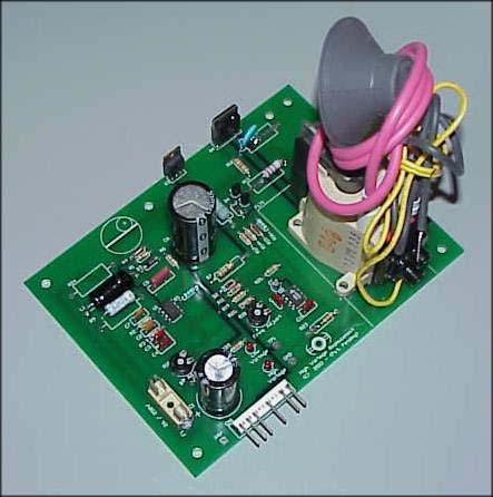
9 Your completed unit should look like the picture below. Finishing Up: Mount your new unit onto your monitor chassis and reconnect all connectors to their correct positions. Double check all your work, make sure the anode ("big suction cup") is firmly in place and everything else looks good. When the HV unit was assembled, it was factory set to its default operating voltages. But since every tube and game is different, the Focus and Screen adjustments were not set. Power-up your game and make sure that both the Low power LED and High Voltage LED are lit. If not then go to the troubleshooting Section.
.")
10 If both LED's light then adjust the Screen and Focus adjustments on the flyback for the best picture (shown below). Congratulations - You're all done.

11 FINE TUNING THE VOLTAGES (optional) If you have access to a voltmeter AND high voltage probe then proceed with this step. If you do not have a voltmeter and HV probe then DO NOT MAKE ANY ADJUSTMENTS to the potentiometers on the new HV PCB. Improper adjustments can cause damage to the unit and your game. If you do not have the correct test equipment leave the B+ setting how it was set at the factory. It will be close enough for a good picture. Turn the B+ adjustment pot fully clockwise. Power up the monitor and check the voltages at TP1 and GND. Very slowly turn the B+ pot counter clockwise until you read between +170 and +175 Volts DC. At this point you have correctly adjusted B+. WARNING -DO NOT ADJUST HIGHER THAN +175 VOLTS DC. Turn off your monitor and hook up your HV probe to the anode of the monitor and ground. Turn on monitor and use the FREQ ADJUST pot to get no more than 19.5 kv DC at the anode.
12 Troubleshooting: Fuse blows: 1. Although the board is marked for a 2 amp fuse the unit needs a 3 to 4 amp fuse. Be sure this is correct. 2. Your transistors are not insulated correctly and are shorted to the aluminum chassis. Double-check the mica insulators for proper installation Low voltage LED and High voltage LED are not lit: 1. Blown fuse 2. You may have a problem with your monitor's Deflection PCB. High Voltage LED not lit: 1. Slightly turn the Freq Adjust pot clockwise until the LED lights. Screen blurry with retrace lines or Dim screen: 1. Adjust the focus and screen adjustments on the flyback transformer. 2. Make sure you have the yellow and black wires connected to the correct red and white wires.
LV2000. revision 1.5. Low Voltage Power Supply Retrofit Kit for Wells-Gardner Color XY Monitor, model 19K6100. Installation Instructions ! WARNING!
 LV2000 revision 1.5 Low Voltage Power Supply Retrofit Kit for Wells-Gardner Color XY Monitor, model 19K6100 Installation Instructions! WARNING! To successfully install this kit requires that you have good
715B CONTROL SERIES. Instruction Manual Line Voltage DC Brushless Motor Control CONTROLS. Phone (317) Fax (317)
 Fax (317)") 715B CONTROL SERIES CONTROLS Instruction Manual Line Voltage DC Brushless Motor Control LT715B (IM-715B-0100) P.O. Box 10 5000 W. 106th Street Zionsville, Indiana 46077 Phone (317) 873-5211 Fax (317) 873-1105
715B CONTROL SERIES CONTROLS Instruction Manual Line Voltage DC Brushless Motor Control LT715B (IM-715B-0100) P.O. Box 10 5000 W. 106th Street Zionsville, Indiana 46077 Phone (317) 873-5211 Fax (317) 873-1105
SUBMERSIBLE MINI-PUMP
 SUBMERSIBLE MINI-PUMP Model 41287 Set up And Operating Instructions Diagrams within this manual may not be drawn proportionally. Due to continuing improvements, actual product may differ slightly from
Plasma Generator Kit. Images Scientific Instruments Inc.
 Images Scientific Instruments Inc. PG13 Plasma Generator Kit This kit generates high voltage using a fly back transformer. The Plasma generator kit can be used for many high voltage experiments. Images
E24-E28 M88 & S38 Mass Air Flow Conversion System Instruction Manual
 E24-E28 M88 & S38 Mass Air Flow Conversion System Instruction Manual Miller Performance Ltd. Tel 855.BMW.TUNER 2009 Abbotsford Way, Abbotsford BC, V2S 6Y5 Millerperformancecars.com Table of Contents: 1.
A/C PRESSURE MONITOR INSTALLATION INSTRUCTIONS SYSTEM OPERATION GREEN INDICATOR LIGHT
 A/C PRESSURE MONITOR INSTALLATION INSTRUCTIONS Do not attempt to clean or inspect anything while the engine is running. Cleaning and inspection must be done by a certified mechanic. All A/C service must
TE020 Ignition Coil Tester
 Page 1 of 23 TE020 Ignition Coil Tester www.dat-equipment.com.au Page 2 of 23 Contents Safety Precautions... 3 Precautions to be taken during usage... 3 Functions... 4 General... 4 Operation... 5 Single
Installation and Operation Instructions Safety Director Arrow
 Installation and Operation Instructions Safety Director Arrow! WARNING! Failure to install or use this product according to manufacturers recommendations may result in property damage, serious bodily/personal
SCA-80(Q) C11 REPLACEMENT ASSEMBLY MANUAL
 C11 REPLACEMENT ASSEMBLY MANUAL") SCA-80(Q) C11 REPLACEMENT ASSEMBLY MANUAL 2014-2016 AkitikA, LLC All rights reserved Revision 1p05 July 3, 2016 Page 1 of 15 Table of Contents Table of Contents... 2 Table of Figures... 2 Section 1: About
SCA-80(Q) C11 REPLACEMENT ASSEMBLY MANUAL 2014-2016 AkitikA, LLC All rights reserved Revision 1p05 July 3, 2016 Page 1 of 15 Table of Contents Table of Contents... 2 Table of Figures... 2 Section 1: About
Safety Sentry Electronic Breakaway Switch
 Safety Sentry Electronic Breakaway Switch P-616-WE 819-0454 Installation Instructions An Altra Industrial Motion Company Parts List Mounting hardware included with the Safety Sentry Breakaway Switch kit:
Electronic Dynamo Regulator INSTRUCTION MANUAL. COPYRIGHT 2014 CLOVER SYSTEMS All Rights Reserved
 DRM TM DRM-HP TM Electronic Dynamo Regulator INSTRUCTION MANUAL COPYRIGHT 2014 CLOVER SYSTEMS All Rights Reserved INTRODUCTION The Clover Systems DRM is a state-of-the art all-electronic voltage and current
DYNACO STEREO 120 C7 REPLACEMENT MANUAL
 DYNACO STEREO 120 C7 REPLACEMENT MANUAL 2013 AkitikA, LLC All rights reserved Revision 1p03 April 29, 2013 Page 1 of 15 Table of Contents Section 1: About This Manual... 3 Who Should Attempt this Project?...
G500REC Manual Covering System for Containers
 10 Boulder Parkway N. Oxford, MA 01537 866-353-5826 pioneersales@wastequip.com www.pioneercoverall.com G500REC Manual Covering System for Containers Installation Manual WARNING: In order to prevent damage,
The function of this Dynamic Active Probe has divided into three preferences on the screen main Menus:
 1.0 Introduction: This probe is designed to provide an additional help to automotive technicians in trouble shooting of electrical circuits problems in the car. Apart from using the normal multi tester,
Biasing the Vintage Series (Nomad, BelAir, VT50, Vintage 33)
") Biasing the Vintage Series (Nomad, BelAir, VT50, Vintage 33) This chapter will outline and guide you through the procedures of biasing the Vintage series amplifier. The procedures are broken down in a
Biasing the Vintage Series (Nomad, BelAir, VT50, Vintage 33) This chapter will outline and guide you through the procedures of biasing the Vintage series amplifier. The procedures are broken down in a
SUNTURA HD SOLAR TRACKER
 WindyNation SUNTURA HD SOLAR TRACKER SOT-TRKS-NFHD User s Manual Page 1 of 11 WindyNation 08/09/2012 Table of Contents 1! Introduction... 3! 1.1! Limited Warranty... 3! 1.2! Restrictions... 3! 1.3! Warranty
E24/E28 M30 Mass Air Flow Conversion System Instruction Manual Version 2.0
 E24/E28 M30 Mass Air Flow Conversion System Instruction Manual Version 2.0 Miller Performance Ltd. Tel 855.BMW.TUNER 2009 Abbotsford Way, Abbotsford BC, V2S 6Y5 Millerperformancecars.com Table of Contents:
SUNTURA SOLAR TRACKER
 WindyNation SUNTURA SOLAR TRACKER SOT-TRKS-NF User s Manual Page 1 of 10 WindyNation 08/09/2012 Table of Contents 1 Introduction... 3 1.1 Limited Warranty... 3 1.2 Restrictions... 3 1.3 Warranty Claims
User s Manual. ClipperCreek, Inc. Innovative Infrastructure for Electric and Hybrid Vehicles. Model PCS-15
 ClipperCreek, Inc. Innovative Infrastructure for Electric and Hybrid Vehicles User s Manual ClipperCreek, Inc. 11850 Kemper Rd., Suite E Auburn, CA 95603 www.clippercreek.net Model PCS-15 THIS PAGE INTENTIONALLY
USB Charge Port Installation Instructions
 USB Charge Port Installation Instructions Lifetime Technical Support support@logolites.com 770-476-7322 www.logolites.com Manual 100-0014C Thank you for purchasing a Logo Lites USB Charge Port! USB Charge
Tri-Spark - Classic Triple Trident & R3 Installation Instructions
 Tri-Spark - Classic Triple Trident & R3 Installation Instructions TRI-0002 Copyright Tri-Spark 2015 Revised June 2015 Thank you for purchasing the Tri-Spark Classic Triple Ignition system. For your own
BLUE LIGHT FOR DYNACO STEREO 120, SCA-80, OR PAT-4 ROCKER SWITCHES
 BLUE LIGHT FOR DYNACO STEREO 120, SCA-80, OR PAT-4 ROCKER SWITCHES 2014 AkitikA, LLC All rights reserved Revision 1p5 April 8, 2014 Page 1 of 16 Table of Contents Table of Contents... 2 Table of Figures...
CBC-300 Series & CBC-300C Series Dual Channel Adjust Clutch/Brake Controls
 CBC-300 Series & CBC-300C Series Dual Channel Adjust Clutch/Brake Controls P-269-89-0408 Installation Installation & Operating Instructions Contents Introduction........................... 2 Specifications.........................
HIGH VOLTAGE POWER SUPPLY REPLACEMENT
 HIGH VOLTAGE POWER SUPPLY REPLACEMENT P/N 6100-0107-03 Tools Required: 1. Screwdriver, straight slot 2. Screwdriver, Phillips #2 3. Nut driver, 1/4" 4. Insulated lead wire 12-15 inches long (No. 18-20)
www. hydrofuse.com Installation Manual Fertilizer Machine V1.3
 www. hydrofuse.com Installation Manual Fertilizer Machine V1.3 Introduction Hydrofuse is a new concept in fertilizing that works with existing irrigation (sprinkler) systems and automatically dispenses
BLUE LIGHT FOR DYNACO STEREO 120 OR PAT-4 ROCKER SWITCHES
 BLUE LIGHT FOR DYNACO STEREO 120 OR PAT-4 ROCKER SWITCHES 2012 AkitikA, LLC All rights reserved Revision 1p3 April 18, 2012 Page 1 of 15 Table of Contents Table of Contents... 2 Table of Figures... 2 Section
How to bias: V3M, V3MC Rev A 9/23/2011
 How to bias: V3M, V3MC Rev A 9/23/2011 www.carvinservice.com - 1 - Only a certified technician should bias Carvin amps, this can be very dangerous, you can get hurt, please be very careful when working
RS-110 Rainfall Sensor Installation Guide
 RS-110 Rainfall Sensor Installation Guide for XR440 and XR5 Data Loggers September 2015 Revision 1.1 1 Disclaimer The following warranty and liability disclaimer apply to this product. PACE SCIENTIFIC
Model HPX60 Series Automatic Battery Charger User s Manual Rev. 1.0 October 17, 2006
 B R A N D Model HPX60 Series Automatic Battery Charger User s Manual Rev. 1.0 October 17, 2006 For Sales, Support and Service phone: 407-331-4793 fax: 407-331-4708 website: www.xenotronix.com email: information@xenotronix.com
1.4 N/1.4 D. Operating Instructions. 580 Mayer Street, Building #7, Bridgeville, PA phone fax
 1.4 N/1.4 D Operating Instructions 580 Mayer Street, Building #7, Bridgeville, PA 15017 phone 412.206.0106 fax 412.206.0146 www.brightlines.com 2006 Brightline, L.P. Safety Warning: Do not dim a non-dim
HALLMARK INDUSTRIES INC
 Performance Part No. HP. CONVERTIBLE JET PUMP USER S MANUAL GPH of Water @ Total Discharge Pressure of 40 psi Max. Pressure Max suction (shallow well) Max Suction (deep well) Max GPM (@0 head) Max Discharge
CBC-802 Plug-In Clutch/Brake Control with Solid State Switching
 DIST. AUTORIZADO Plug-In Clutch/Brake Control with Solid State Switching P-29-5 19-0409 Service & Installation Instructions An Altra Industrial Motion Company DIST. AUTORIZADO Brake (Red) and clutch (Green)
Test Equipment Depot Washington Street Melrose, MA TestEquipmentDepot.com INSTRUCTION MANUAL PSMR1
 Test Equipment Depot - 800.517.8431-99 Washington Street Melrose, MA 02176 - TestEquipmentDepot.com INSTRUCTION MANUAL PSMR1 Introduction Descriptions All the information you need in one device. Verify
Pick and Hold Module Pin Assignment and Description
 CONNECTION SIGNAL DESCRIPTION CONNECTION SIGNAL DESCRIPTION J1 + PWR This pin should be connected to the positive output of the driver power supply. The maximum voltage applied This should pin should not
CAPACITOR ACTUATED PORTABLE STARTER CAPS USER GUIDE. INST048 Doc 3.01
 CAPACITOR ACTUATED PORTABLE STARTER CAPS USER GUIDE INST048 Doc 3.01 CONTENTS General Information...2 Charts...3 Before First Use...4 Safety Requirements...5 What to Expect from the CAPS...5 CAPS Diagram...6
Installation MKIV Headlight Housings with Fog Lamps (Procedures apply to both MKIV Jetta and Golf)
") Page 1 This tutorial is provided as a courtesy by ECS Tuning. Service Procedure Installation Proper service and repair procedures are vital to the safe, reliable operation of all motor vehicles as well
Page 1 This tutorial is provided as a courtesy by ECS Tuning. Service Procedure Installation Proper service and repair procedures are vital to the safe, reliable operation of all motor vehicles as well
Instruction Manual. Backup Camera System With Replacement Mirror Display RVS N
 Instruction Manual Backup Camera System With Replacement Mirror Display RVS-778718N Rear View Safety, Inc. 2016 1 NOTE! Please read all of the installation instructions carefully before installing the
SYSTEM MANUAL. Automated Motorized Hydraulic Traffic Controller. Revision CS72-HTC
 CS72-HTC SYSTEM MANUAL Automated Motorized Hydraulic Traffic Controller Revision 2002.01 Spike Systems 3623 S. Seventh Street Phoenix, Arizona 85040 Phone: (602) 243-0291 Fax: (602) 243-0294 Hydraulic
TK08 TUNING KIT TECHNICAL MANUAL FOR 16/26/27/28 SERIES SHOCKS Revised 6/17/14
 Tech Line: (952) 985-5675 Fax (952) 985-5679 21730 Hanover Ave. Lakeville, MN 55044 www.qa1.net www.facebook.com/qa1motorsports TK08 TUNING KIT TECHNICAL MANUAL CONTENTS UNDER PRESSURE! USE EXTREME CAUTION
CHAPTER 2. Current and Voltage
 CHAPTER 2 Current and Voltage The primary objective of this laboratory exercise is to familiarize the reader with two common laboratory instruments that will be used throughout the rest of this text. In
KSZ 10B Current Probe Calibrator. Instruction Manual
 KSZ 10B Current Probe Calibrator Instruction Manual Copyright 2011 PMK GmbH All rights reserved. Information in this publication supersedes that in all previously published material. Specifications are
SB SWITCH CONTROL BOX
 Carson Manufacturing Co., Inc. 5451 North Rural Street Indianapolis, IN 462 Phone: (888) 577-6877 Fax: (317) 254-2667 www.carsonsirens.com SB-008-25 SWITCH CONTROL BOX INSTALLATION AND OPERATING INSTRUCTIONS
Owner s Manual GLASSLINED PUMP TANK
 Owner s Manual GLASSLINED PUMP TANK ANSI/NSF 61 Annex G Thank You for purchasing a pump tank. Properly installed and maintained, it should give you years of trouble free service. If you should decide that
CELL PREPARATION AND INSTALLATION INSTRUCTIONS
 HYDRO~STICK Water Fuel Cell CELL PREPARATION AND INSTALLATION INSTRUCTIONS DISCLAIMER: This Product is designed and constructed based on the current best practices and state of the art concepts of the
12 Volt Utility Controller for 4, 6 or 8 Brakes No P
 12 Volt Utility Controller for 4, 6 or 8 Brakes No. 1300-77 P-1379 819-0094 Installation Instructions Introduction The Warner Electric manually operated Utility Controller operates 4, 6, or 8 twelve-volt
TK08 TUNING KIT TECHNICAL MANUAL FOR 16/26/27/28 SERIES SHOCKS Revised 6/25/14 Tech Line: (952) Fax (952)
 Fax (952)") Tech Line: (952) 985-5675 Fax (952) 985-5679 21730 Hanover Ave. Lakeville, MN 55044 www.qa1.net www.facebook.com/qa1motorsports TK08 TUNING KIT TECHNICAL MANUAL CONTENTS UNDER PRESSURE! USE EXTREME CAUTION
Tech Line: (952) 985-5675 Fax (952) 985-5679 21730 Hanover Ave. Lakeville, MN 55044 www.qa1.net www.facebook.com/qa1motorsports TK08 TUNING KIT TECHNICAL MANUAL CONTENTS UNDER PRESSURE! USE EXTREME CAUTION
Turn Signal Kit Installation Instructions for Model A Fords & Other Antique Vehicles
 Turn Signal Kit Installation Instructions for Model A Fords & Other Antique Vehicles Lifetime Technical Support support@logolites.com 770-476-7322 www.logolites.com Manual 100-0005N Thank you for purchasing
Utility Controller Hand Air Operated
 Utility Controller Hand Air Operated P-1395 819-0288 Installation Instructions Introduction The Warner Electric air/manual Utility Controller combines manual and automatic (air) actuation for the operation
Installation Instructions for Part #: KRB01 Radiator and Reserve Tank Relocation Kit for K-Powered Civics
 Installation Instructions for Part #: KRB01 Radiator and Reserve Tank Relocation Kit for K-Powered 1992-1995 Civics This kit provides the SOLUTION for mounting a factory or factory replacement radiator
CTFRP Series Power Supplies
 CTFRP Series Power Supplies Ferroresonant Non-Standby Power Supplies User Manual Myers Power Products 6/2013 CTFRP Series Manual Chapter 1 General Information The Myers CTFRP Series Power Supply provides
SIDE-WIND, A-FRAME TRAILER JACK. Model Due to continuing improvements, actual product may differ slightly from the product described herein.
 SIDE-WIND, A-FRAME TRAILER JACK Model 95157 Assembly And Operation Instructions Due to continuing improvements, actual product may differ slightly from the product described herein. 3491 Mission Oaks Blvd.,
ECS R32 Exhaust Flap Manual Override Installation Instructions
 Installation Procedures This tutorial is provided as a courtesy by. Proper service and repair procedures are vital to the safe, reliable operation of all motor vehicles as well as the personal safety of
NEW GEN OWNER S MANUAL
 NEW GEN OWNER S MANUAL For Models: LT-ELP223Q LT-ELP116Q 1 2! Turn off the light when not in use to conserve battery power. CAUTION! If you need to mount the flashlight onto a firearm, make sure firearm
HBC-20 - LED HIGH BAY
 To prevent death, injury or damage to property, this product must be installed in accordance to National Electrical Code (NFPA70) in the US or Canadian Electrical Code (CSA.) in Canada. Risk of fire or
Battery Charger Retrofit Kit Q-DCCHG1 for DC Cabinet Retrofit Manual
 Battery Charger Retrofit Kit Q-DCCHG1 for DC Cabinet Retrofit Manual 25500181 Rev. A0 415 Printed in U.S.A. Copyright 2015 Federal Signal Corporation Limited Warranty The Alerting and Notification Systems
QUASAR ELECTRONICS KIT No ELECTRONIC CAR IGNITION
 QUASAR ELECTRONICS KIT No. 1058 ELECTRONIC CAR IGNITION General Description The advantages of having an electronic ignition in your car are well known. Let us mention them again: 1. Perfect burning of
Models DP10 & DP20 Series Low Voltage Disconnects User s Manual Rev. 1.1 October 31, 2007
 B R A N D Models DP10 & DP20 Series Low Voltage Disconnects User s Manual Rev. 1.1 October 31, 2007 For Sales, Support and Service phone: 407-331-4793 fax: 407-331-4708 website: www.xenotronix.com email:
Order Number MOP C2. Microwave Oven
 Order Number MOP0107026C2 Microwave Oven 2 2001 Matsushita Electric Industrial Co., Ltd. All rights reserved. Unauthorized copying and distribution is a violation of law. 1 Inverter Warning The inverter
CBC-802 Plug-In Clutch/Brake Control with Solid State Switching
 CBC-02 Plug-In Clutch/Brake Control with Solid State Switching P-2104-WE 19-054 Service & Installation Instructions An Altra Industrial Motion Company Brake (Red) and clutch (Green) indicator lights When
Model NTX7 Series Automatic Battery Charger User s Manual Rev. 1.0 October 17, 2006
 B R A N D Model NTX7 Series Automatic Battery Charger User s Manual Rev. 1.0 October 17, 2006 For Sales, Support and Service phone: 407-331-4793 fax: 407-331-4708 website: www.xenotronix.com email: information@xenotronix.com
Filtered PWM Speed Control for Permanent Magnet DC Motors
 Instructions for Installation and Operation Filtered PWM Speed Control for Permanent Magnet DC Motors Model 0794 Speed and Direction Control up to 5/8 HP NEMA-1/IP-20 Specifications Product Type:... WPM-2148E1
110 Volt/12 Volt Portable Inflator
 110 Volt/12 Volt Portable Inflator Owner s Manual WARNING: Read carefully and understand all ASSEMBLY AND OPERATION INSTRUCTIONS before operating. Failure to follow the safety rules and other basic safety
Electrometer Lead Acid Battery Replacement
 Electrometer Lead Acid Battery Replacement Table of Contents NOTE: Although this manual is provided by Standard Imaging as a reference, battery replacement by anyone other than a trained Standard Imaging
G213V STEP MOTOR DRIVE REV 7: March 25, 2011
 Thank you for purchasing the G213V drive. The G213V is part of Geckodrive s new generation of CPLD-based microstep drives. It has short-circuit protection for the motor outputs, over-voltage and under-voltage
37SCENE 46SCENE 79SCENE
 Installation and Operation Instructions LED SCENE LIGHT LED SCENE LIGHT 37SCENE 46SCENE 79SCENE 37SCENE 46SCENE Introduction The 37SCENE, 46SCENE, 79SCENE LED Scene Lights are designed for the emergency
Installation Manual TWM Performance Short Shifter Cobalt SS/SC, SS/TC, HHR SS, Ion Redline and Saab 9-3
 Page 1 Installation Manual TWM Performance Short Shifter Cobalt SS/SC, SS/TC, HHR SS, Ion Redline and Saab 9-3 Please Note: It is preferable to park on a flat surface, as you will have to engage and disengage
DC POWER SUPPLY ALIMENTATION C.C.
 DC POWER SUPPLY ALIMENTATION C.C. ISO-TECH IPS 303A 201-3424 ISO-TECH IPS 601A 201-3446 SAFETY TERMS AND SYMBOLS These terms may appear in this manual or on the product: WARNING. Warning statements identify
The Da-Lite Difference.
 The Da-Lite Difference. Instruction Book for Boardroom Electrol DA-LITE SCREEN COMPANY, INC. 3100 North Detroit Street Post Office Box 137 Warsaw, Indiana 46581-0137 Phone: 574-267-8101 800-622-3737 Fax:
BLDC SPEED CONTROL INSTRUCTION MANUAL Low voltage Brushless DC control
 BLDC SPEED CONTROL INSTRUCTION MANUAL Low voltage Brushless DC control Phone 712.722.4135 groschopp.com 420 15th St NE, Sioux Center, IA 51250 Toll-Free 800.829.4135 Email sales@groschopp.com FAX 712.722.1445
Electrometer NiCad Battery Replacement
 Electrometer NiCad Battery Replacement Table of Contents NOTE: Although this manual is provided by Standard Imaging as a reference, battery replacement by anyone other than a trained Standard Imaging employee
User s Manual Power Supply. IM E 2nd Edition. Yokogawa Electric Corporation
 User s Manual 701934 Power Supply Yokogawa Electric Corporation 2nd Edition Foreword Revisions Thank you for purchasing the 701934 Power Supply. This user's manual contains useful information about the
LIFT MATE BOAT LIFT MOTOR ASSEMBLY. Assembly and Operating Manual.
 LIFT MATE BOAT LIFT MOTOR ASSEMBLY Assembly and Operating Manual www.boatliftmotor.com 03/26/2010 LIMITED WARRANTY Shoreline Industries, Inc. warrants its products shall be free from defects in materials
DC TO AC POWER INVERTER PWRIC150012W INSTRUCTION MANUAL
 DC TO AC POWER INVERTER PWRIC150012W INSTRUCTION MANUAL SAVE THIS MANUAL You will need the manual for the safety warnings and precautions, assembly instructions, operating and maintenance procedures, parts
RapidLED Oceanic BioCube 8 Retrofit Contents
 RapidLED Oceanic BioCube 8 Retrofit Contents Foreword... 2 Outline... 2 Hood Preparation... 2 Attaching LEDs to Heatsink and Wiring LEDs Together... 6 Thermal Grease... 6 Soldering Notes... 7 Tinning Wire
16 Inch Hanging Pendant Barn Light
 16 Inch Hanging Pendant Barn Light Owner s Manual WARNING: Read carefully and understand all ASSEMBLY AND OPERATION INSTRUCTIONS before operating. Failure to follow the safety rules and other basic safety
OWNER S MANUAL AUTOMATIC DISCHARGE PUMP CONTROLLER
 TankMaster 4 AUTOMATIC DISCHARGE PUMP CONTROLLER OWNER S MANUAL Dometic Corporation Sanitation Systems 13128 State Rt 226, PO Box 38 Big Prairie, OH 44611 SeaLand Product Customer Service: 1-800-321-9886
MOD 102 GUITAR AMP KIT (K-MOD102)
") MOD 0 GUITAR AMP KIT (K-MOD0) ON BASS TREBLE VOLUME MOD 0 TUBE AMP KIT 0 0 0 0 0 0 OFF Use these instructions to learn: How to build a tube amp. This tube guitar amplifier circuit is based on a classic
MOD 0 GUITAR AMP KIT (K-MOD0) ON BASS TREBLE VOLUME MOD 0 TUBE AMP KIT 0 0 0 0 0 0 OFF Use these instructions to learn: How to build a tube amp. This tube guitar amplifier circuit is based on a classic
PD-20 HIGH VOLTAGE PROBE INSTRUCTION MANUAL
 PD-20 HIGH VOLTAGE PROBE INSTRUCTION MANUAL Index 1. Safety precaution... 2. Specifications... 3. Operation... 4. Warning... 5. Cleaning... 6. Rated environmental conditions... 7. Observe the international
12 Volt Heavy-Duty Air Inflator
 12 Volt Heavy-Duty Air Inflator Owner s Manual WARNING: Read carefully and understand all ASSEMBLY AND OPERATION INSTRUCTIONS before operating. Failure to follow the safety rules and other basic safety
Audi B9 A4 & S4 Carbon Fiber Steering Wheel Trim Installation Instructions
 Audi B9 A4 & S4 Carbon Fiber Steering Wheel Trim Installation Instructions Proper service and repair procedures are vital to the safe, reliable operation of all motor vehicles as well as the personal safety
model ps600 Address all communications and shipments to: FEDERAL SIGNAL CORPORATION
 MODEL: PS600 HZ: 60 A model ps600 installation and service manual for federal model ps600 FEDERAL SIGNAL CORPORATION POWER SUPPLY VOLTS: SERIES: 120VAC FEDERAL SIGNAL CORPORATION UNIVERSITY PARK, IL. U.S.A.
The POWER. In PRESENTATION PRODUCTS. Instruction Book for COSMOPOLITAN ELECTROL For Sizes Up To 9'x12' DA-LITE SCREEN COMPANY, INC.
 The POWER In PRESENTATION PRODUCTS Instruction Book for COSMOPOLITAN ELECTROL For Sizes Up To 9'x12' DA-LITE SCREEN COMPANY, INC. 3100 North Detroit Street Post Office Box 137 Warsaw, Indiana 46581-0137
Handyman Motor Capacitor Meter PART NO
 Handyman Motor Capacitor Meter PART NO. 2225174 To test a motor-run capacitor in the field with no capacitance meter at hand, you had to hook up the capacitor through an extension cable to a 120V wall
FiveFish Studios PSU-2448Plus+ Assembly Guide
 FiveFish Studios PSU-2448Plus+ Assembly Guide Copyright 2015-2017 FiveFish Audio Revision 1.02-20171105 No part of this document may be reproduced, either mechanically or electronically, posted online
SAVE THESE INSTRUCTIONS
 12 Volt High-V Volume Air Inflator Owner s Manual WARNING: Read carefully and understand all ASSEMBLY AND A OPERATION INSTRUCTIONS before operating. Failure to follow the safety rules and other basic safety
USER AND SAFETY MANUAL
 USER AND SAFETY MANUAL HANDLE- BARS STEM COLLAR ROD SADDLE SAFETY HOOK- STRIP BRAKE SUPPORT BARS AFT TUBE FRONT TUBE SAFETY RULES SECURE THE ROD AND ATTACH SAFETY HOOK-STRIP before every ride. RIDE WHEELA
SAFETY PRECAUTIONS AND WARNINGS...
 Table of Contents 1. SAFETY PRECAUTIONS AND WARNINGS... 1 2. USING THE TEST TOOL... 2 2.1 TOOL DESCRIPTION... 2 2.2 SPECIFICATIONS... 3 2.3 ACCESSORIES INCLUDED... 3 2.4 GENERAL DESCRIPTION... 4 2.5 POWER...
6 OFF ROAD LIGHT BAR
 6 OFF ROAD LIGHT BAR LOUD speaker Model 95953 Set up And Operating Instructions Diagrams within this manual may not be drawn proportionally. Due to continuing improvements, actual product may differ slightly
GF-30AC. Ground Circuit Tester COMPLIANCE WESTUSA. Instruction Manual
 GF-30AC Ground Circuit Tester Instruction Manual COMPLIANCE WESTUSA Dear Customer: Congratulations! Compliance West USA is proud to present you with your Ground Fault Circuit Tester. Your instrument features
ELECTRIC FENCE ENERGIZER SERVICE MANUAL MODEL 950 SERVICE MANUAL FOR OLLI 950 FENCE ENERGIZERS
 ELECTRIC FENCE ENERGIZER MODEL 950 SERVICE MANUAL Service Manual for OLLI 950 Page 1/16 Date 20.10.2014 Table of Contents...1 1. IMPORTANT SAFETY INSTRUCTIONS...2 2. SPECIFICATIONS...3 3. CONSTRUCTION...4
I. Safety precautions
 . Safety precautions The items described in these instructions and on the inverter itself are very important so that you can use the inverter safely, prevent injury to yourself and other people around
KSZ 100B Current Probe Calibrator. Instruction Manual
 KSZ 100B Current Probe Calibrator Instruction Manual 2 Copyright 2011 PMK GmbH All rights reserved. Information in this publication supersedes that in all previously published material. Specifications
USER S MANUAL GPC SERIES LOW VOLTAGE DISCONNECT. Galley Power LLC.
 USER S MANUAL GPC SERIES LOW VOLTAGE DISCONNECT Galley Power LLC www.galleypower.com Table of Contents Safety Notice... 3 Disclaimer... 3 Safety Instructions... 4 1. Introduction... 5 1.1 Features and
Outrigger 4 A 12 Volt DC Power Pole Distribution Panel
 Outrigger 4 A 12 Volt DC Power Pole Distribution Panel The outrigger 4 is a 5 way 12 volt DC power pole distribution board with 1 input and 4 outputs. It is a compact (4.25 x 2.25 Inch PCB) unit comprising
G203V / G213V MANUAL STEP MOTOR DRIVE
 G203V / G213V MANUAL STEP MOTOR DRIVE PRODUCT DIMENSIONS PHYSICAL AND ELECTRICAL RATINGS Minimum Maximum Units Supply Voltage 18 80 VDC Motor Current 0 7 A Power Dissipation 1 13 W Short Circuit Trip 10
O W N E R ' S M A N U A L
 1500 Watt DC to AC Power Inverter C o n v e r t s 1 2 V D C B a t t e r y P o w e r t o 1 1 0 V A C H o m e P o w e r O W N E R ' S M A N U A L SAVE THESE INSTRUCTIONS The recommended source of power is
OUTDOOR TABLE TENNIS TABLE ASSEMBLY INSTRUCTIONS
 OUTDOOR TABLE TENNIS TABLE ASSEMBLY INSTRUCTIONS Please Do Not Hesitate to Contact Our Consumer Hotline at 800-759-0977 with Any Questions That May Arise During Assembly or Use of This Product! NG2336P
EFIE Wideband O2 (Electronic Fuel Injector Enhancer) Installation & Operating Instructions.
 Installation & Operating Instructions.") EFIE Wideband O2 (Electronic Fuel Injector Enhancer) Installation & Operating Instructions. The EFIE is not intended to be a fuel saver by itself. The EFIE is designed to be used in conjunction with fuel
EFIE Wideband O2 (Electronic Fuel Injector Enhancer) Installation & Operating Instructions. The EFIE is not intended to be a fuel saver by itself. The EFIE is designed to be used in conjunction with fuel
MDCKB VAC, 8A Brushless Controller. User s Guide E. Landon Drive Anaheim, CA
 MDCKB1-120081 120VAC, 8A Brushless Controller User s Guide A N A H E I M A U T O M A T I O N 4985 E. Landon Drive Anaheim, CA 92807 e-mail: info@anaheimautomation.com (714) 992-6990 fax: (714) 992-0471