IV-3 VFD Shield for Arduino. Assembly Manual
|
|
|
- Adrian Fletcher
- 5 years ago
- Views:
Transcription
1 June 2014
2 Table of Contents 1 Overview Features Applications Assembly Hints 4 3 PCB Overview 5 4 Circuit Diagram 6 5 Assembly Diodes and IC socket Electrolytic capacitors Ceramic capacitors 10K resistors 68K resistors 100K resistors 220K resistors Remaining resistors Arduino headers Power transistors NPN transistors PNP transistors Tube backlighting LEDs VFD tube mounting Final Test 13 7 Legal Information Disclaimer Trademarks Contact Information 14 Revision History Date Authors Ilse Joostens 2 Description Initial release.
3 1 Overview This Arduino shield is capable of driving 4 Russian IV-3 7 segment VFD tubes. 4 3mm LEDs provide background lighting for the tubes. The design is completely based on through hole components, no SMD components were used. As such, the PCB can easily be assembled by anyone who has some soldering experience. Also, the components used are cheap and easily available. As this was designed as a more educational, easy to build project it is not the best possible solution to drive these VFD tubes from a technical point of view. Instead of the BC547 and BC557 transistors we could have used A2982W source drivers, or we could have replaced the transistors by a Supertex high voltage source driver IC with internal shift register. Unfortunately these may be hard to get and come very often in SMD packages. Features Compatible with Arduino boards. Drives 4 IV-3 VFD tubes. Power supply 12V DC + 5V DC (from Arduino board). Enclosure design (CAD files) available. Applications Clock. Score board. Thermometer. Counter. 3
4 2 Assembly Hints This kit is designed for someone who has advanced experience with assembling electronics. If you believe that the kit is too complicated for your skill level please do not try to assemble it. Take your time - this kit should take 2-3 hours to complete if uninterrupted. Ensure your work area is well lit (daylight preferred) and clean. Assemble the board in the order as stated in the instructions - read and understand each step before you perform each operation. It is assumed that you understand that semiconductors (diodes, ICs, transistors) and electrolytic capacitors are polarized components. Appropriate markings are silk-screened on the PCB and shown on the board schematic. The following tools and materials will be required to assemble the PCB: A good quality soldering iron (25-40W) with a small tip (1-2 mm). Wire cutter and pliers. Basic multimeter for voltage tests and for identifying the resistors. A magnifying glass to read the small device markings is often helpful. Solder lead / tin solder is preferred. Lead free solder, as now required to be used in commercial products in Europe, has a much higher melting point and can be very hard to work with. Do not use any flux or grease. Desoldering wick (braid) can be useful if you accidentally create solder bridges between adjacent solder joints. Power supply The IV-3 VFD shield needs the Arduino to be powered from a 12 V DC power supply to function properly. Use a regulated switching power adapter capable of delivering 12 V DC / 300 ma. Do not use an unregulated "transformer style" wall adapter. These deliver easily more than 16 V with a light load and will cause damage to the IV-3 VFD shield as the 12 V supply voltage is quite critical. Put some insulating tape on the metal shield of the USB connector of your Arduino before connecting the IV-3 shield to avoid solder connections touching the metal and being shorted. 4

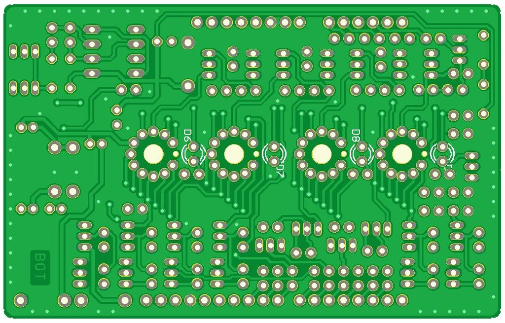
5 3 PCB Overview 5
6 4 Circuit Diagram 6


7 5 Assembly In the following pages we are going to assemble the PCB step by step. It may be helpful to keep the PCB overview and the circuit diagram at hand during assembly. After every step, carefully compare your PCB with the pictures in the manual and check for errors and solder faults. Diodes and IC socket Mount the following diodes: D1: 1N400x or equivalent D2...D5: 1N5819 schottky diode Watch the polarity and be careful to mount the right diode in the right place. Solder D2 and D3 from the component side and trim the wires on the solder side as short as possible as they are positioned above the metal USB connector shielding of the Arduino. Mount the 8 pole IC socket for IC1. Do not place IC1 in the socket at this stage. Electrolytic capacitors Mount the following electrolytic capacitors: C5...C8: 22µF 50V radial electrolytic capacitor C9, C10: 100µF 25V radial capacitor Bend the leads 90 degrees and mount the capacitors flush to the PCB. Watch the polarity. It is recommended to solder C6, C7 and C8 from the component side and to trim the leads as short as possible on the solder side as they are positioned above the metal shield of the Arduino USB connector. 7


8 Ceramic capacitors Mount the capacitors: following C1: 2n2 C2, C3: 8n2 C4: 100n ceramic Please note that the values of C1...C3 are somewhat critical as C1 defines together with R5 the operating frequency of the voltage tripler and C2, C3 define the filament current for the IV-3 tubes. 10K resistors Mount the 10 kilo ohm resistors (brown black orange gold) R6...R18. Mount them vertically as shown in the picture. 68K resistors Mount the 68 kilo ohm resistors (blue grey orange gold) R19...R30. Mount them vertically as shown in the picture. 8

 R2,")

9 100K resistors Mount the 100 kilo ohm resistors (brown black yellow gold) R31...R42. Mount them vertically as shown in the picture. 220K resistors Mount the 220 kilo ohm resistors (red red yellow gold) R43...R54. Mount them vertically as shown in the picture. Remaining resistors Mount the remaining resistors: R1: 510 ohm (green brown brown gold) R2, R3: 1 kilo ohm (brown black red gold). You may need to adjust the value depending on the tube backlight LEDs you plan to use. R4: 2.7 kilo ohm (red violet red gold) R5: 3.9 kilo ohm (orange white red gold) 9


10 Arduino headers Mount the Arduino stackable headers. The headers will not really be used to stack other Arduino shields on top of this shield but they help to determine the mounting height of several components and the IV-3 tubes. Push the headers through the PCB and plug them in your Arduino. Turn upside down and solder 1-2 pins for each connector. So the connector spacing will be correct. Remove the shield from the Arduino and solder the remaining pins. Power transistors Mount the following transistors: T26: BC639 T27: BC640 Do not replace these transistors with standard types. Mount them so that the top of their housings is lower than the Arduino headers. Insert IC1 ICM7555 into its socket and plug the shield into an Arduino and apply power. The voltage measured between the cathode of D5 and the Arduino ground should be around V NPN transistors Mount the BC547B transistors T1 T13. Mount them so that the top of their housings stays below (or is flush with) the Arduino headers. 10

 is soldered to the pad closest to the LED name silk-screen marking (D6 D8).")
11 PNP transistors Mount the BC557B transistors T14 T25. Mount them so that the top of their housings stays below (or is flush with) the Arduino headers. Tube backlighting LEDs You can use 3mm standard LEDs in any color for tube backlighting purposes, even RGB color fading LEDs. Bend the leads of the LEDs so that the LEDs fit in the 3mm holes underneath the VFD tubes, then solder them to the pcb. Pay attention to polarity. The short lead of the LED (cathode) is soldered to the pad closest to the LED name silk-screen marking (D6 D8). It may be necessary to insulate the leads of D9 to avoid them touching the ISP connector on the Arduino. The LEDs are connected to a PWM output on the Arduino and can be dimmed using software. This will however not work properly when you use RGB color fading LEDs. If it is easier for you, it is also possible to mount the LEDs after the VFD tubes are soldered in place. Due to the mounting technique, it is also easy to replace the LEDs later on if you decide you would like to have another backlighting color. 11


12 VFD tube mounting Guide the tube wires gently through their respective holes on the PCB. Make sure the short lead on the tubes goes through the hole without solder pad. Now the digits should face the front of the PCB. If you have difficulties getting the wires of the tubes through the holes you can cut them as a "spiral" so you can move 1 wire at a time through the holes. Pay attention to make the shortest wire not too short as we are going to mount the tubes with some distance from the pcb. Once the tubes are in place align them more or less by hand. The bottom of the tubes should be approximately 1-2 mm below the top of the Arduino stackable headers. If you are using the optional acrylic enclosure, you can use the top and bottom plates as an alignment tool. Solder two leads of each tube to the PCB. Once this is done, you can still adjust the tube alignment by reheating the solder joints. If you are satisfied with the tube alignment, you can finally solder the remaining tube wires in place and trim the excess leads with a small wire cutter. Do not try to change the alignment of a tube after it is soldered in place as this may cause mechanical stress and may lead to a defective tube. 12


13 6 Final Test Upload the demo sketch from the Axiris website to the Arduino and disconnect the Arduino from the computer's USB port. Plug the finished IV-3 VFD shield on top of the Arduino. Make sure no metal part of the Arduino touches the solder joints of the IV-3 VFD shield. Connect the 12 V DC power adapter to the Arduino power connector and turn the power on. After a few seconds the VFD tubes should start counting from 0 to 9 in an endless loop. The decimal separator dots of the VFD tubes should form a binary 4 bit counter. Tube backlighting should dim and turn on again every few seconds. Check the tube filament wires carefully. They should glow very faintly with a deep red color. If they are glowing too much, lower the values of C2 and C3. On the other hand, if the filament barely glows and the digits are too dim, you can experiment by increasing the values for C2 and C3. 13
14 7 Legal Information Disclaimer Axiris products are not designed, authorized or warranted to be suitable for use in space, nautical, space, military, medical, life-critical or safety-critical devices or equipment. Axiris products are not designed, authorized or warranted to be suitable for use in applications where failure or malfunction of an Axiris product can result in personal injury, death, property damage or environmental damage. Axiris accepts no liability for inclusion or use of Axiris products in such applications and such inclusion or use is at the customer's own risk. Should the customer use Axiris products for such application, the customer shall indemnify and hold Axiris harmless against all claims and damages. Trademarks All product names, brands, and trademarks mentioned in this document are the property of their respective owners. 8 Contact Information Official website: 14
Total solder points: 187 Difficulty level: beginner advanced. Code lock K6400 ILLUSTRATED ASSEMBLY MANUAL
 Total solder points: 187 Difficulty level: beginner 1 2 3 4 5 advanced Code lock K6400 Ged rid of those old fashioned keys ILLUSTRATED ASSEMBLY MANUAL H6400IP-2 Features & Specifications Features: More
SCA-80(Q) C11 REPLACEMENT ASSEMBLY MANUAL
 C11 REPLACEMENT ASSEMBLY MANUAL") SCA-80(Q) C11 REPLACEMENT ASSEMBLY MANUAL 2014-2016 AkitikA, LLC All rights reserved Revision 1p05 July 3, 2016 Page 1 of 15 Table of Contents Table of Contents... 2 Table of Figures... 2 Section 1: About
SCA-80(Q) C11 REPLACEMENT ASSEMBLY MANUAL 2014-2016 AkitikA, LLC All rights reserved Revision 1p05 July 3, 2016 Page 1 of 15 Table of Contents Table of Contents... 2 Table of Figures... 2 Section 1: About
K3500 MULTIFUNCTION CAR COURTESY LIGHT. Specifications
 Total solder points: 87 Difficulty level: beginner 1 2 3 4 5 advanced MULTIFUNCTION CAR COURTESY LIGHT K3500 Never look for the ignition switch in the dark again. Specifications switch-off delay: adjustable
Bill of Materials: Car Battery/charging system diagnostics PART NO
 Car Battery/charging system diagnostics PART NO. 2192106 You can hook up the kit's test leads directly to the car battery (with engine off) and see whether battery voltage is ok (green LED on) or low (yellow
SUPER CAPACITOR CHARGE CONTROLLER KIT
 TEACHING RESOURCES ABOUT THE CIRCUIT COMPONENT FACTSHEETS HOW TO SOLDER GUIDE POWER YOUR PROJECT WITH THIS SUPER CAPACITOR CHARGE CONTROLLER KIT Version 2.0 Teaching Resources Index of Sheets TEACHING
Total solder points: Difficulty level: beginner advanced 3 DIGIT PANEL METER KIT K2032 ILLUSTRATED ASSEMBLY MANUAL
 Total solder points: 65 + 49 Difficulty level: beginner 1 2 3 4 5 advanced 3 DIGIT PANEL METER KIT K2032 Ideal replacement for moving coil meters ILLUSTRATED ASSEMBLY MANUAL H2032IP-1 Features & Specifications
C capacitance, 91 capacitors, codes for, 283 coupling, polarized and nonpolarized,
 Index Numbers and Symbols 555 timer, 164 166 making sound using, setting output speed of, 166 167 using for reaction game speed, 260 261 μf (microfarad), 92 Ω (ohms), 7, 70 A A (amperes), 7 AC (alternating
Total solder points: 20 Difficulty level: beginner advanced UNIVERSAL BATTERY CHARGER K7302 ILLUSTRATED ASSEMBLY MANUAL
 Total solder points: 20 Difficulty level: beginner 1 2 3 4 5 advanced UNIVERSAL BATTERY CHARGER K7302 Low cost soluton for charging of both NiCd and NiMh batteries. ILLUSTRATED ASSEMBLY MANUAL H7302IP-1
Ljunggren Audio Roll Your Own Optodist
 Ljunggren Audio Roll Your Own Optodist Version: Optodist/VCA.0 Bill Of Material TYPE PART VALUE PCS NOTE Resistor R,R 0R Resistor R5,R0 K Resistor R3,R4 0K Resistor R,R9 68K Resistor R 00K Resistor R3
ASSEMBLY INSTRUCTIONS FOR NEW FK109 4 LED Railroad Crossing Flasher Kit WITH ADJUSTABLE FLASHING SPEED CONTROL with 4 Red 3mm Leds
 ASSEMBLY INSTRUCTIONS FOR NEW FK109 4 LED Railroad Crossing Flasher Kit WITH ADJUSTABLE FLASHING SPEED CONTROL with 4 Red 3mm Leds Description: Very easy to build, The FK109 Led Flasher kit makes the perfect
Total solder points: 126 Difficulty level: beginner advanced POWER DIMMER 230V) K8038 ILLUSTRATED ASSEMBLY MANUAL
 K8038 ILLUSTRATED ASSEMBLY MANUAL") Total solder points: 126 Difficulty level: beginner 1 2 3 4 5 advanced POWER DIMMER (1KW @ 230V) K8038 NOISE SUPPRESSED ACCORDING TO EN55015 Class microcontroller high power dimmer with non volatile memory
Total solder points: 126 Difficulty level: beginner 1 2 3 4 5 advanced POWER DIMMER (1KW @ 230V) K8038 NOISE SUPPRESSED ACCORDING TO EN55015 Class microcontroller high power dimmer with non volatile memory
CAPI BB2521 Build Guide & BOM
 This is a very simple build. I only have a few tips and things to look out for. I do recommend following these steps due to the diode/transistor relationship. 1. Install the three ceramic caps. If you
Total solder points: 93 Difficulty level: beginner advanced 10 LED MONO VU METER K4304 ILLUSTRATED ASSEMBLY MANUAL
 Total solder points: 93 Difficulty level: beginner 1 2 3 4 5 advanced 10 LED MONO VU METER K4304 Add a visual readout to your existing or new equipment. ILLUSTRATED ASSEMBLY MANUAL H4304IP-1 Features &
SM361 RIG SWITCH CONSTRUCTION MANUAL
 SM361 RIG SWITCH CONSTRUCTION MANUAL Document ver 1, For software release ver 1.1 May 27, 2016 Controls the power of 12V equipment while a vehicle is in use Product Development by: SM361 RIG SWITCH OVERVIEW
SB-GVS Shield v1.0. ! Ideal for servo & sensor accessories (Phidgets, Seeed Bricks)! Full break-out for all 12 digital lines & 6 analog lines 2
! Full break-out for all 12 digital lines & 6 analog lines 2") SB-GVS Shield v1.0 Arduino tm -Compatible Sensor Interface Connect up 18 peripherals to the popular Ground/Voltage/Signal interface. Got more? Use the IC-interface too! Build Time: 0mins Skill Level: Beginner
SB-GVS Shield v1.0 Arduino tm -Compatible Sensor Interface Connect up 18 peripherals to the popular Ground/Voltage/Signal interface. Got more? Use the IC-interface too! Build Time: 0mins Skill Level: Beginner
CTB-16K Hobbyist Line Kit 40 Amp 16 Channel Light Controller Assembly Manual *** Preliminary ***
 CTB-16K Hobbyist Line Kit 40 Amp 16 Channel Light Controller Assembly Manual *** Preliminary *** Version 1.0 January 12, 2006 Copyright Light O Rama, Inc. 2006 Table of Contents 1 Introduction... 3 2 Required
MONGOOSE. Introduction. < blueroomelectronics > Assembly Instructions. Mongoose was designed as an introduction to Mechatronics.
 MONGOOSE Assembly Instructions Introduction Mongoose was designed as an introduction to Mechatronics Page 1 of 12 Before you start The Mongoose is a complex kit and skipping instructions is not advised,
Qrpkits.com 10 Watt SMT Dummy Load Assembly and Operating Manual
 Qrpkits.com 10 Watt SMT Dummy Load Assembly and Operating Manual Introduction The Hendricks 10 Watt (DC 150MHz) 50 Ohm Dummy Load kit is a compact, SMT (Surface Mount Technology) design, that in addition
Schematic VCC J1 1 CON1 +5V D26 D25 D7 D8 D9 D10 D11 D12 D19 D20 D21 D22 D23 D24 D1 D2 D3 D4 D5 D6 D13 D14 D15 D16 D17 D18 R4 100R R2 100R R6 100R
 Schematic +5V S D1 D2 D3 D4 D5 D6 D7 D8 D9 D10 D11 D12 D19 D20 D21 D22 D23 D24 D13 D14 D15 D16 D17 D18 D25 D26 R1 4K7 R2 100R Q1 9014-PNP C1 47uF R3 4K7 R4 100R Q2 9014-PNP C2 47uF R5 4K7 R6 100R Q3 9014-PNP
2xVCX version 1.0. Calibration instructions can be found on the last page. Capacitor bypass MLCC X7R mm pin pitch
 Produced by: Roll Your Own ljunggrenaudio.com Schematic & PCB Design by: KYMATICA DEVICES www.kymatica.com xvcx version.0 Bills Of Material Bold = PCB C C C3 C4 C5 C6 C7 C8 C9 C0 C C C3 C4 CON D D D3 D4
Ljunggren Audio Roll Your Own Penta
 Ljunggren Audio Roll Your Own Penta Version: Penta 1.0 Bills Of Material Bold = PCB1, The rest = PCB2 Type Parts Des cription Pow er header Qty Value 1 2x5pin POWER Euro pow er connector Jack 1 3.5mm J1,
General Purpose Flasher Circuit
 General Purpose Flasher Circuit By David King Background Flashing lights can be found in many locations in our neighbourhoods, from the flashing red light over a stop sign, a yellow warning light located
IV-11 VFD tube clock Assembly instructions v1.2.2
 IV-11 VFD tube clock Assembly instructions v1.2.2 Designer: Website: E-mail: Yan Zeyuan. China http://www.nixieclock.org yanzeyuan@qq.com 2017-01-26 NCH Attention Attention: Warning: Warning: Warning:
Tip: LED Lighting for the 4367 SBB Euro City Set, 4366 and 4368 Cars Date: , Corrections Modified , Photos
 Hi All, I have had the 4367 SBB Euro City set with extra cars 4366 and 4368 since 1998, apart from a test run on the layout they have stayed in storage ever since. I decided to change some rolling stock
Lab Electronics Reference: Tips, Techniques, and Generally Useful Information for the Labs
 ENGR 112 September 16, 14 Lab Electronics Reference: Tips, Techniques, and Generally Useful Information for the Labs This guide contains some useful reference information to help get you started on your
Assembly Manual for New Control Board 22 June 2018
 Assembly Manual for New Control Board 22 June 2018 Parts list Arduino 1 Arduino Pre-programmed 1 Faceplate Assorted Header Pins Full Board Rev A 9 104 capacitors 1 Rotary encode with switch 1 5-volt regulator
Tip: LED Lighting Improvements for Rheingold Set Date:
 Hi All, Recently I came into possession of the 41928 Rheingold set and was excited to see that I could add a function decoder to switch the light functions on and off. The first problem is Märklin don
WINDUP TORCH KIT TEACHING RESOURCES. Version 1.1 LIGHT UP YOUR DAY WITH THIS
 TEACHING RESOURCES SCHEMES OF WORK DEVELOPING A SPECIFICATION COMPONENT FACTSHEETS HOW TO SOLDER GUIDE LIGHT UP YOUR DAY WITH THIS WINDUP TORCH KIT Version 1.1 Index of Sheets TEACHING RESOURCES Index
Quiz Buzzer. Build Instructions. Issue 1.2
 Build Instructions Issue 1.2 Build Instructions Before you put any components in the board or pick up the soldering iron, just take a look at the Printed Circuit Board (PCB). The components go in the side
FiveFish Studios PSU-2448Plus+ Assembly Guide
 FiveFish Studios PSU-2448Plus+ Assembly Guide Copyright 2015-2017 FiveFish Audio Revision 1.02-20171105 No part of this document may be reproduced, either mechanically or electronically, posted online
BehringerMods.com. Instructions for modification of Behringer DCX analog inputs and outputs
 BehringerMods.com Instructions for modification of Behringer DCX analog inputs and outputs The following instructions will cover the details of fully modifying a unit with analog output and analog input
100W SUBWOOFER KIT. Total solder points: 383 Difficulty level: beginner advanced K8077 ILLUSTRATED ASSEMBLY MANUAL
 100W SUBWOOFER KIT Powerful bass from a small cabinet thanks to the dual speaker principle Total solder points: 383 Difficulty level: beginner 1 2 3 4 5 advanced K8077 ILLUSTRATED ASSEMBLY MANUAL H8077IP-1
REAR BIKE LIGHT KIT TEACHING RESOURCES. Version 2.0 MASTER THE ART OF SOLDERING WITH THIS
 TEACHING RESOURCES SCHEMES OF WORK DEVELOPING A SPECIFICATION COMPONENT FACTSHEETS HOW TO SOLDER GUIDE MASTER THE ART OF SOLDERING WITH THIS REAR BIKE LIGHT KIT Version 2.0 Index of Sheets TEACHING RESOURCES
Assembly Instructions for the KA Electronics Flat MM Phono Preamplifier
 Assembly Instructions for the KA Electronics Flat MM Phono Preamplifier Install IC sockets Flat MM Phono Preamp PC Board Stuffing Guide Place the PC Board on the bench silkscreen side face up. Drop six
G213V STEP MOTOR DRIVE REV 7: March 25, 2011
 Thank you for purchasing the G213V drive. The G213V is part of Geckodrive s new generation of CPLD-based microstep drives. It has short-circuit protection for the motor outputs, over-voltage and under-voltage
BLUE LIGHT FOR DYNACO STEREO 120, SCA-80, OR PAT-4 ROCKER SWITCHES
 BLUE LIGHT FOR DYNACO STEREO 120, SCA-80, OR PAT-4 ROCKER SWITCHES 2014 AkitikA, LLC All rights reserved Revision 1p5 April 8, 2014 Page 1 of 16 Table of Contents Table of Contents... 2 Table of Figures...
D6, D7, D8, D9, D12, D13, D14, D15, D16, D17, D18, D19. Schottky rectifier diode. 1N5817-1N5819 or SB130
 Roll Your Own ljunggrenaudio.com Altered States version 1.0 Bills Of Material Qty Value 12 1N4148 2 1N5818 4 1N750 4.7V 4 220p Device Diode Diode Zener diode Capacitor 30 100n 4 15p 8 560p 1 5x2 pin Capacitor
THE WAHTZ WAH (K-985)
") THE WAHTZ WAH (K-985) Output Jack Unplug from the Wahtz input jack (other side) when not in use to save battery life. 9 VDC CENTER (-) ADAPTER Use these instructions to learn: How to build a wah-wah pedal
THE WAHTZ WAH (K-985) Output Jack Unplug from the Wahtz input jack (other side) when not in use to save battery life. 9 VDC CENTER (-) ADAPTER Use these instructions to learn: How to build a wah-wah pedal
EMG SpikerShield v1.2 Instructions
 EMG SpikerShield v1.2 Instructions Prepare yourself. In 2-4 hours, you will have built your own Arduino compatible EMG SpikerBox, so you can control robots and anything you wish with your EMG muscle activity.
Kit1 300B Edition. Single Ended Triode 8 Watt. Construction Manual & User Guide Volume One
 Kit1 300B 2014 Edition Single Ended Triode 8 Watt Construction Manual & User Guide Volume One Contents Section 1: Receiving your kit...2 Section 2: The Mechanical section Preparation... 3 Tang Strips...
Adding an LED indicator to the X10-WS467 wall switch Credit: Bruce Stydnicki
 1 of 6 1/2/2009 4:33 PM Adding an LED indicator to the X10-WS467 wall switch Credit: Bruce Stydnicki 1. I had a need to monitor the status of my outdoor lights which are connected to X10-WS467 wall switches.
CHRISTMAS TREE KIT MODEL K-14. Assembly and Instruction Manual ELENCO
 CHRISTMAS TREE KIT MODEL K-14 Assembly and Instruction Manual ELENCO Copyright 2015, 1989 by Elenco Electronics, Inc. All rights reserved. Revised 2015 REV-J 753214 No part of this book shall be reproduced
QUASAR ELECTRONICS KIT No ELECTRONIC CAR IGNITION
 QUASAR ELECTRONICS KIT No. 1058 ELECTRONIC CAR IGNITION General Description The advantages of having an electronic ignition in your car are well known. Let us mention them again: 1. Perfect burning of
Chapter 2. Battery Charger and Base Assembly
 Chapter 2 Battery Charger and Base Assembly 11 CHAPTER 2. BATTERY CHARGER AND BASE ASSEMBLY 2.1 Section Overview This Lab teaches students how to assemble a Tekbot, in the following steps: Describe the
PSL2 Assembly guide. PSL2 Assembly guide. Resistors. Test pins. Document revision 1.1 Last modification : 30/05/08
 Safety warning THIS KIT IS NOT FOR BEGINNERS! This kit is main powered and use potentially lethal voltages. Under no circumstance should someone undertake the realisation of this kit unless he has full
INTRODUCTION TOOLS AND SUPPLIES Universal Kit-building Tools:
 TABLE OF CONTENTS Introduction...2 Tools and Supplies...2 Before You Start Building...3 Soldering Tips:...3 Desoldering Tips:...4 Work Habits:...4 Sorting and Reading Resistors:...4 Reading Capacitors:...5
Build Instructions and User Guide
 Build Instructions and User Guide Getting Started To build the Rock Drill 4069 you will need: Solder Wire Cutters Soldering Iron Small pliers The kit is suitable for beginners or more experienced builders
Tip: 3425 Kittle Loco with LP4.0 Micro Conversion and LED Lighting Date: , Corrections Addition Link added
 Hi All, This is the last of Rudolf s LokPilot Micro V4.0 decoder conversions. He asked me to convert his Märklin Delta 3425 steam locomotive and wanted to improve the lighting effects for the cabin, change
QRPGuys Digital RF Probe
 QRPGuys Digital RF Probe First, familiarize yourself with the parts and check for all the components. If a part is missing, please contact us and we will send one. This kit contains seventeen 1206 size
PAT-4 TOROIDAL TRANSFORMER ASSEMBLY MANUAL
 PAT-4 TOROIDAL TRANSFORMER ASSEMBLY MANUAL 2015 AkitikA, LLC All rights reserved Revision 1p3 August 22, 2015 Page 1 of 13 Table of Contents Table of Contents... 2 Table of Figures... 2 Section 1: About
QUASAR KIT No THYRISTOR - TRIAC TESTER
 QUASAR KIT No. 1087 THYRISTOR - TRIAC TESTER GENERAL DESCRIPTION With this new kit Quasar Kit offers you a very useful instrument for your bench that will help you to test THYRISTORS and TRIACS. These
RGB Alarm Clock. -Color Alarm Clock-
 RGB Alarm Clock -Color Alarm Clock- Table of Contents Preamble:...2 List of parts...3 Components...5 Parts and belongings...5 Clock Board Assembly...8 Identification of SMD parts:...0 The power supply
DECIDUOUS FILTER ASSEMBLY INSTRUCTIONS RECOMMENDED TOOL AND SUPPLY LIST DECIDUOUS FILTER KIT PARTS LIST
 DECIDUOUS FILTER ASSEMBLY INSTRUCTIONS Thank you for purchasing the Deciduous Filter Effect Pedal Kit from Mammoth Electronics! This is an intermediate level kit and we have made every effort to make the
BATTERY TESTER KIT TEACHING RESOURCES. Version 2.0 MEASURE THE REMAINING CAPACITY OF AA BATTERIES WITH THIS
 TEACHING RESOURCES SCHEMES OF WORK DEVELOPING A SPECIFICATION COMPONENT FACTSHEETS HOW TO SOLDER GUIDE MEASURE THE REMAINING CAPACITY OF AA BATTERIES WITH THIS BATTERY TESTER KIT Version 2.0 Index of Sheets
G203V / G213V MANUAL STEP MOTOR DRIVE
 G203V / G213V MANUAL STEP MOTOR DRIVE PRODUCT DIMENSIONS PHYSICAL AND ELECTRICAL RATINGS Minimum Maximum Units Supply Voltage 18 80 VDC Motor Current 0 7 A Power Dissipation 1 13 W Short Circuit Trip 10
22K (red red orange gold) 1pcs. 33K (orange orange orange gold) 5pc. 2.7 M (green violet red gold) 2pc.
 1pcs. 33K (orange orange orange gold) 5pc. 2.7 M (green violet red gold) 2pc.") TURNING FROG Long pliers, soldering, soldering iron stand with sponge, 2 AA batteries, one 9V battery, Tin, diagonal cutting pliers Turning Frog is a robot that uses a microphone as a detector. When microphone
TURNING FROG Long pliers, soldering, soldering iron stand with sponge, 2 AA batteries, one 9V battery, Tin, diagonal cutting pliers Turning Frog is a robot that uses a microphone as a detector. When microphone
THE PERSUADER DELUXE (K-980)
") THE PERSUADER DELUXE (K-0) BOOST VOLUME GAIN Unplug when not in use to save battery life. TO AMP IN The Persuader Deluxe Tube Drive modkitsdiy.com FROM GUITAR OUT LED VDC CENTER (-) ADAPTER Use these instructions
THE PERSUADER DELUXE (K-0) BOOST VOLUME GAIN Unplug when not in use to save battery life. TO AMP IN The Persuader Deluxe Tube Drive modkitsdiy.com FROM GUITAR OUT LED VDC CENTER (-) ADAPTER Use these instructions
BLUE LIGHT FOR DYNACO STEREO 120 OR PAT-4 ROCKER SWITCHES
 BLUE LIGHT FOR DYNACO STEREO 120 OR PAT-4 ROCKER SWITCHES 2012 AkitikA, LLC All rights reserved Revision 1p3 April 18, 2012 Page 1 of 15 Table of Contents Table of Contents... 2 Table of Figures... 2 Section
~Dashboard Digital Voltmeter~
 ~Dashboard Digital Voltmeter~...November, 2002 This project is helpful to anyone who drives an automobile. I had found this project at the local libary... in an old publication. I made it and it worked
How to Convert the IBM VAC Power Supply to 230 VAC
 How to Convert the IBM 5150 120 VAC Power Supply to 230 VAC Discussion The 120VAC version of the 5150's power supply, as-designed, is not switch or jumper-configurable for 230VAC operation. However, there
ECO-6 & Installation Manual
 ECO-6 & Installation Manual For the SPA4-RFR Upgrade Kit To upgrade SPA4 amplifiers v1.00 & v1.01 to v2.0 Some sections also apply to the PA1, PA2, and PA3 14 August 2015 2015 by Ralph Hartwell Spectrotek
QUASAR ELECTRONICS KIT No WINDSCREEN WIPER CONTROLLER
 QUASAR ELECTRONICS KIT No. 1093 WINDSCREEN WIPER CONTROLLER General Description This is a very useful accessory for any car. It can adjust the frequency of operation of the windscreen wipers between once
CHAPTER 2. Current and Voltage
 CHAPTER 2 Current and Voltage The primary objective of this laboratory exercise is to familiarize the reader with two common laboratory instruments that will be used throughout the rest of this text. In
Tip: 2856 LED Lighting for the Airport Express Set Date:
 Hi All, The 2856 Airport Express set was manufactured in 1983. On 09-11-1989 the locomotive was given a digital upgrade using a 6080 decoder. It has since had a digital upgrade to a high performance motor
ez1081pre Mic Amplifier - Assembly manual [ Colourbook Issue 1]
![ez1081pre Mic Amplifier - Assembly manual [ Colourbook Issue 1]](/thumbs/90/103906919.jpg "ez1081pre Mic Amplifier - Assembly manual [ Colourbook Issue 1]") ez1081pre Mic Amplifier - Assembly manual [ Colourbook Issue 1] ez1081pre Colourbook Contents. Section 1 - Colourbook assembly guide Section 2 - Setup and Calibration Section 3 - Schematics diagrams and
ez1081pre Mic Amplifier - Assembly manual [ Colourbook Issue 1] ez1081pre Colourbook Contents. Section 1 - Colourbook assembly guide Section 2 - Setup and Calibration Section 3 - Schematics diagrams and
Uno Compatible Pogobed Kit
 Uno Compatible Pogobed Kit Intermediate Level The pogobed kit is a hardware fixture that enables you to temporarily connect from your Arduino development board to any Arduino shield. Using the springloaded
ALARM KIT ESSENTIAL INFORMATION. Version 2.0 WHAT CAN YOU PROTECT WITH THIS
 ESSENTIAL INFORMATION BUILD INSTRUCTIONS CHECKING YOUR PCB & FAULT-FINDING MECHANICAL DETAILS HOW THE KIT WORKS WHAT CAN YOU PROTECT WITH THIS ALARM KIT Version 2.0 Build Instructions Before you start,
KORG KR-55. µsync installation guide version 1.0, 14 October
 KORG KR-55 µsync installation guide version 1.0, 14 October 2016 www.artefacts.nl Introduction The Korg KR-55 or KR-55b has no standard din sync input. Artefacts developed a piece of hardware to convert
Norcal Power/SWR Meter Assembly & Operating Manual. Revision 1D 10/15/2008
 Norcal Power/SWR Meter Assembly & Operating Manual Revision 1D 10/15/2008 Copyright 2008 NorCal QRP Club Page 1 of 21 Contents CONTENTS...2 INTRODUCTION...3 SPECIFICATIONS...3 ASSEMBLY...4 OPERATING GUIDE...15
ALARM KIT TEACHING RESOURCES. Version 2.0 WHAT CAN YOU PROTECT WITH THIS
 TEACHING RESOURCES SCHEMES OF WORK DEVELOPING A SPECIFICATION COMPONENT FACTSHEETS HOW TO SOLDER GUIDE WHAT CAN YOU PROTECT WITH THIS ALARM KIT Version 2.0 Index of Sheets TEACHING RESOURCES Index of Sheets
MOTHMAN FUZZ ASSEMBLY INSTRUCTIONS RECOMMENDED TOOL AND SUPPLY LIST MOTHMAN FUZZ KIT PARTS LIST
 MOTHMAN FUZZ ASSEMBLY INSTRUCTIONS Thank you for purchasing the J201 Clean Boost Pedal Kit from Mammoth Electronics! This is a intermediate level kit that and we have made every effort to make the assembly
KI0007EP BICYCLE TAIL LIGHT LED FLASHER PROJECT
 KI0007EP BICYCLE TAIL LIGHT FLASHER PROJECT Designed and Supplied by ABN 26 052 173 154 Unit 4 Cnr Ring Rd & Sturt St, Ballarat Victoria, 3350 P.O Box 4043, Alfredton, 3350 www.wiltronics.com.au sales@wiltronics.com.au
HW-8-LM386 Audio Amplifier Board Assembly Instructions
 This LM386 based audio amplifier kit was designed to replace the small audio amplifier board in the Heathkit HW-8 transciever. The result is the ability to drive regular modern day 8 ohm headphones or
PR-101 STEREO PREAMPLIFIER
 PR-101 STEREO PREAMPLIFIER Headphone Amp ASSEMBLY MANUAL 2015, 2016 AkitikA LLC All rights reserved Revision 1p9 May 6, 2016 Page 1 of 21 Table of Contents Table of Contents... 2 Table of Figures... 3
BUMP AND SPIN KIT TEACHING RESOURCES. Version 1.1 PROGRAM AND DESIGN YOUR OWN BUGGY WITH THIS
 TEACHING RESOURCES SCHEMES OF WORK DEVELOPING A SPECIFICATION COMPONENT FACTSHEETS HOW TO SOLDER GUIDE PROGRAM AND DESIGN YOUR OWN BUGGY WITH THIS BUMP AND SPIN KIT Version 1.1 Index of Sheets TEACHING
Tip: - Württemberg Era 1 Open Platform Cars LED Lighting Upgrade Date: , Photos
 Hi All, As I continue my LED light conversions of my rolling stock I have just completed all the Württemberg era 1 open platform cars I have which will make up four trains with eight cars per train. These
THERMOMETER PROJECT KIT
 TEACHING RESOURCES SCHEMES OF WORK DEVELOPING A SPECIFICATION COMPONENT FACTSHEETS HOW TO SOLDER GUIDE MEASURE INDOOR AND OUTDOOR TEMPERATURES WITH THIS THERMOMETER PROJECT KIT Version 2.0 Index of Sheets
BURGLAR ALARM KIT MODEL K-23. Assembly and Instruction Manual ELENCO
 BURGLAR ALARM KIT MODEL K-23 Assembly and Instruction Manual ELENCO Copyright 2017, 1989 ELENCO Electronics, Inc. Revised 2017 REV-R- 753223 No part of this book shall be reproduced by any means; electronic,
Elecraft Transverter Models XV50, XV144, XV222. Assembly Manual. Rev D, September 13, 2010 Copyright 2010, Elecraft; All Rights Reserved
 Elecraft Transverter Models XV50, XV144, XV222 Assembly Manual Rev D, September 13, 2010 Copyright 2010, Elecraft; All Rights Reserved Table of Contents INTRODUCTION... 1 CUSTOMER SERVICE AND SUPPORT...
Installation of Raxiom Switchback Turn Signal Conversion Kit w/resistors
 Installation of Raxiom Switchback Turn Signal Conversion Kit w/resistors Overview: Below are the steps involved in the installation of the Raxiom Switchback Turn Signal LED lights in the 1987 1993 Ford
IR Gun Assembly Instructions
 IR Gun Assembly Instructions Rev 1.01 SenselessDevices.com 1 Description The IR Gun is part of a shooting Arcade project. Together with the target kits, a variety of shooting galleries can be constructed.
Tip: and Orient Express LED Light Upgrade Date: Correction
 Hi All, I have since inherited my friend Rudolf s 42755 Orient Express with the extra 42760 car set and wanted to complete the LED light upgrade as we had planned. Side view of the Restaurant car with
These instructions show how to build the Remote Controlled Fart machine Sound Kit.
 Remote Controlled Fart Machine Assembly Instructions These instructions show how to build the Remote Controlled Fart machine Sound Kit. Tools Required Drill with 7/64, 3/16, and ¼ drill bits. Holt melt
Mableaudio Company limited
 Mableaudio Company limited Web: www.mableaudio.com [5E3 assembly manual] Tel:0086-755-83996326 fax:0086-755-83996326 Contact: Ms Mable mable@mableaudio.com WARNING! This amp operates at voltages that may
BATTERY BOOSTER SHIELD
 BATTERY BOOSTER SHIELD Introduction The Battery Booster Shield is an add-on for the Arduino that efficiently boosts a lower input voltage (0.65V to 4.5V) up to 5V. It powers the Arduino and peripherals
Maplin Cordless Screwdriver Repair
 Written By: Philip Le Riche ifixit CC BY-NC-SA www.ifixit.com Page 1 of 10 INTRODUCTION This budget cordless screwdriver was sold in the UK by Maplin (no longer trading) but the same or very similar products
White Light CLASSIC PEDAL KIT. Assembly Instructions WHEN YOU CAN T BUY IT BUILD IT. StewMac RARE / VINTAGE / HARD TO GET
 Sheet #i-2206 Updated 5/18 StewMac White Light CLASSIC PEDAL KIT Kit case is unpainted IN COLLABORATION WITH EarthQuakerDevices Assembly Instructions The White Light Overdrive is based on vintage overdrives
Elecraft Transverter Model XV432. Assembly Manual. Rev D, July 18, 2012 Copyright 2012, Elecraft; All Rights Reserved
 Elecraft Transverter Model XV432 Assembly Manual Rev D, July 18, 2012 Copyright 2012, Elecraft; All Rights Reserved Table of Contents INTRODUCTION... 2 CUSTOMER SERVICE INFORMATION... 2 Technical Assistance...
PM-200 POWER SUPPLY MODULE v3.2 ASSEMBLY & INSTALLATION INSTRUCTIONS
 PM-200 POWER SUPPLY MODULE v3.2 ASSEMBLY & INSTALLATION INSTRUCTIONS WARNING: Voltages inside the amplifier CAN & WILL KILL YOU! You MUST know how to work around HIGH VOLTAGE safely. If you do not, get
Battery Board Manual (v 1.)
") Battery Board Manual (v 1.) The Raspberry Pi Battery Board was created as a compact and easy to use portable power source for the Raspberry Pi. Several ways of connecting a battery to the board have been
Battery Board Manual (v 1.) The Raspberry Pi Battery Board was created as a compact and easy to use portable power source for the Raspberry Pi. Several ways of connecting a battery to the board have been
Plasma Generator Kit. Images Scientific Instruments Inc.
 Images Scientific Instruments Inc. PG13 Plasma Generator Kit This kit generates high voltage using a fly back transformer. The Plasma generator kit can be used for many high voltage experiments. Images
Bill of Materials: Spinning top brushless DC motor PART NO
 Spinning top brushless DC motor PART NO. 2171006 The heart of this kit consists of a bifilar wound coil driven with two NPN transistors. While the circuit is easy, the coil will be tedious to wind since
CLASSIC PEDAL KIT. Assembly Instructions WHEN YOU CAN T BUY IT BUILD IT. StewMac Monarch RARE / VINTAGE / HARD TO GET
 Sheet #i-2205 Updated 2/8 StewMac Monarch CLASSIC PEDAL KIT Kit case is unpainted IN COLLABORATION WITH EarthQuakerDevices Assembly Instructions The Monarch Overdrive is an all discrete, FET-based dirt
Assembly Instructions
 Assembly Instructions for the PA3 3.1 MHz Switch Mode Plasma Tube Amplifier Kit PA3 Amplifier shown mounted on HS2 Heat Sink (The HS2 shown here is not included with this kit.) Manual v1.01 30 September
MOD 102 GUITAR AMP KIT (K-MOD102)
") MOD 0 GUITAR AMP KIT (K-MOD0) ON BASS TREBLE VOLUME MOD 0 TUBE AMP KIT 0 0 0 0 0 0 OFF Use these instructions to learn: How to build a tube amp. This tube guitar amplifier circuit is based on a classic
MOD 0 GUITAR AMP KIT (K-MOD0) ON BASS TREBLE VOLUME MOD 0 TUBE AMP KIT 0 0 0 0 0 0 OFF Use these instructions to learn: How to build a tube amp. This tube guitar amplifier circuit is based on a classic
Nistune Z32 ECU Modifications for R33 RB25DET Skyline Installation
 Nistune Z32 ECU Modifications for R33 RB25DET Skyline Installation Revision 10 26 May 2013 Thanks to Eric at DTA Motorsports and Andrew H for their help with previous versions. Many thanks and credits
Assembly and User Guide
 Assembly and User Guide 2 Amp Adjustable Electronic Load 30V and 20 Watts Max Powered by: 9V Battery Pico Load is a convenient constant current load for testing batteries and power supplies. The digital
SMART LAB PUTTING TOGETHER THE
 PUTTING TOGETHER THE SMART LAB INSTALLING THE SPRINGS The cardboard workbench with all the holes punched in it will form the base to the many cool circuits that you will build. The first step in transforming
LED Flasher. R1 R2 100 F + C1 100 F +
 LED Flasher. Specification Operates from a 6-12V supply. Alternately flashes two LEDs. Flash rate adjustable by changing the capacitor values and the 10k resistor values. Circuit Diagram 9V LED1 470 TR1
The ability to make basic voltage and resistance measurements using a digital multimeter
 Seventh Circle Audio C84 Microphone Preamp Based on the innovative Double Balanced Microphone Amplifier circuit published by Graham John Cohen in 1984, the C84 microphone preamp offers exceptional performance