(2 DPDT 2 4 X
|
|
|
- Magnus Garrett
- 6 years ago
- Views:
Transcription
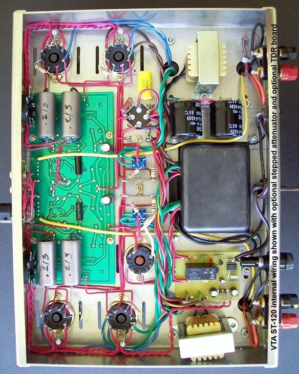
1 Dynaco ST-120 with VTA driver board Kit instruction manual Triode/Pentode version Congratulations on your purchase of the Dynaco ST-120 with VTA driver board kit. Every effort has been made to give you the finest sounding, most reliable and best looking 60 watt per channel kit presently available. ALL parts in this kit are NEW there are no recycled parts from older original Dynaco amplifiers. Your Dynaco kit features the following items which are all upgrades from the original Dynaco kits. 1. A new STAINLESS STEEL chassis that is identical in size, shape and markings to the older original nickel plated steel frame. This chassis is NON-MAGNETIC and removes any magnetic interference effects of a steel chassis on the audio circuitry. 2. Quality USA made A custom wound output transformers which are interleaved/layerwound and incorporate high quality M-6 grain oriented laminations. 3. A more robust PA power transformer rated at 120 volts, having secondaries and a 450 milliamp current transfer capability. 4. Quality Celanex tube sockets 5. All stainless steel screws with zinc plated kep nuts 6. An 80, 40, 30, 20 main electrolytic cap with a 525 volt continuous use rating. 7. An all triode VTA driver board made of mil-spec epoxy fiberglass. This board also contains an on board bias supply for the output tubes and eight premium Sprague 716P film and foil coupling caps. 8. Gold plated input and output terminals. 9. A dual choke system rated at 400 milliamps 10. Triode/pentode switches to allow the amp to run in two modes of operation 11. A supplementary cap module with ESL reduction capacitors The KIT comes with a very easy to follow instruction manual and a clear pictorial specific to the VTA driver board. All you need is to complete the kit is a soldering pencil, some rosin core solder, a screwdriver, pliers and a wire cutter/stripper to build your own Dynaco ST-120. The kit takes about hours to build depending on your skill level and any previous experience with kit building. List of Parts 1 - Stainless Steel chassis frame with bottom cover 1 - VTA driver board with parts set 7-8 pin Celanex octal tube sockets 1 USA made PA power transformer 4 - hard rubber isolation washers for power transformer 2 - A USA made custom interleave/layer wound output transformers 2 - C-354 chokes 1 - multi section 525 volt rated (80, 40, 30, 20) quadruple capacitor 1 - three lug terminal strip 1 - one lug terminal strip 1 - pair of gold plated RCA input jack jacks with mounting board 2 - pair of gold plated output binding posts with mounting board 1 - rubber grommet 1 - fuse post with 5 amp SLO-BLO fuse 2 - SPST slide switches 1-13 amp rated AC power cord Mfd 600 volt capacitors ohm 1 watt resistors 4-10 ohm 2 watt bias resistors ohm 2 watt resistor for quad cap 1 Supplementary Cap Module (SCM) 1 Set of ESL reduction capacitors 1 - hardware kit for amp 1-22 foot coil of 20 gauge tinned solid core copper wire 1 triode/pentode kit (2 DPDT switches, two 2 lug terminal strips, 4 X 100 ohm 1 watt resistors) OPTIONAL > One tube set 4 X 6550 or KT88, 3 X 12AT7, 1 X GZ34 rectifier
2 Optionally painting the transformers Power and output transformers come from the factory with minor surface imperfections. You may, as an option, paint your transformers for a better appearance with some type of heat resistant paint. Recommended, are any type of paint used to paint automobile engine blocks (engine enamel) or paint used to paint barbecue grilles. To most people a semi-gloss paint looks best on transformers. Use a spray can don t brush it on. Recommended paints are Krylon BBQ and Stove paint (Krylon # 1618) OR any type of semi-gloss automobile engine enamel in a spray can. This is carried by Wal- Mart and many other stores. Go to an auto supply store for engine enamel. 1. Obtain SIX 8 X 32 machine screws 2 ½ to 3 inches long with nuts. 2. Remove one transformer 8 X 32 nut, nylon spacer(s) and screw and replace it with one of the six machine screws and nut. Tighten the nut securely. 3. Do the same for the transformer screw on the opposite diagonal corner of the transformer. 4. Remove the other two 8 X 32 screws, nylon spacers and nuts on that transformer. 5. Repeat steps 2 through 4 for the other two transformers. 6. Sand any imperfections in the factory paint off the three transformers with 100 grit paper. Sand again with 220 grit paper 7. Remove all sanding dust from the outer surface of the transformer. 8. Cover the transformer wires by placing them in a plastic bag. Use some masking tape near the transformer to hold the bag on the wires. 9. Spray 3 light coats on each transformer and allow to dry overnight. 10. Remove the plastic bags that cover the wires 11. Reinstall all the original screws, spacers and nuts.
3 ASSEMBLY INSTRUCTIONS NOTE You may or may not want to construct the VTA driver board BEFORE or AFTER you attach the chassis parts. If you wish to construct the VTA driver board at this time skip ahead to the VTA driver board instructions which are inside the VTA package and proceed with its construction. When you are through come back to this point and begin mounting the chassis parts. Obtain the chassis. Remove the four stainless steel 6 X 32 screws. Taped inside the chassis are four one inch round rubber feet which you may stick on the outside of the chassis bottom cover over the four holes in the cover. Orient the chassis with the power transformer cutout facing you and mark V1, V2, V3, V6 and V7 with a felt tip marker on the inside of the chassis next to the appropriate tube socket as marked on the pictorial. The symbol (S) means to solder that connection at that time. If you don t see the symbol do not solder that connection at that time. 1. Mount the FIVE octal sockets that fit on the chassis TOP from the BOTTOM OF THE CHASSIS with ¼ inch long 4-40 stainless steel screws and 4-40 kep nuts. Use the pictorial to orient the keyway of each tube properly. On V2, V3 and V6 mount a GROUND LUG around the outside screw closest to the side of the chassis and face the lug towards pin 8. On V7 mount TWO GROUND LUGS around the outside screw face one towards pin 8 and one towards pin 2. Tighten all nuts securely. DO NOT MOUNT the two front power take off tube sockets at this time. 2. Disassemble the two gold plated speaker binding posts from the mounting plates. Attach the LEFT and RIGHT mounting plates to the back INSIDE of the amp with 4-40 hardware. Reassemble the speaker binding posts on to the mounting plates. One of the black spacers with rounded edges goes INSIDE the chassis and the other black spacer goes OUTSIDE the chassis. Make sure that the BLACK terminal is on the side that says G on the outside of the chassis frame. Tighten the two studs with the gold plated nuts provided. 3. Mount the rubber grommet in the 3/8 inch hole in the back CENTER of the chassis. 4. Mount the fuse holder in the "D shaped hole in the back of the chassis. Tighten the nut but do not over tighten as this may cause the plastic threads to break. Check and make sure that the 5 amp SLO-BLO fuse is inside the fuse holder. 5. Mount the SPST on/off switch on the REAR of the chassis with 4-40 hardware. Make sure that the two terminals on this switch are close to the UNDERSIDE OF THE CHASSIS TOP SURFACE. Check the pictorial. 6. Place the 4 rubber isolation washers on the ends of each of the four bolts of the PA power transformer. Mount the power transformer in the large center cut out. The wires should face the FRONT of the chassis. Fasten the power transformer to the chassis with four 8-32 kep nuts. In the original amp a metal cable clamp was used on each of the two front bolts as seen on the pictorial. These clamps are not really necessary as the wires will stay in place fine when soldered. 7. Assemble the Supplementary Cap Module (SCM) A. Obtain the four lug terminal strip from the SCM kit plastic bag B. Hold the strip with the grounded lug that attaches to the chassis towards you - that grounded lug is lug 1 and the next three lugs are lugs 2, 3 and 4. C. Connect a 330K resistor between lugs 1 and 2 - have the resistor straight in line with the terminal strip and not on the side of the lug. D. Connect a jumper wire between lugs 2 and 3 - have the jumper straight in line with the terminal strip and not on the side of the lug. E. Connect a 330K resistor between lugs 3 and 4 - have the resistor straight in line with the terminal strip and not on the side of the lug. F. Connect a 4 inch wire to lug 4 and run the wire to the side opposite the ground lug attachment hole. G. Obtain one of the two supplementary caps and connect the NEGATIVE terminal of this cap (the terminal with the BLACK STRIPE next to it) to lug 1 of the terminal strip. Connect it on the side OPPOSITE the chassis attachment hole. (S) Fit the other lug of this cap into lug 2 of the terminal strip (S) H. Fit the OTHER supplementary cap on the OTHER SIDE of the terminal strip with the NEGATIVE terminal (the terminal with the BLACK STRIPE next to it) in lug 3 (S) and the POSITIVE terminal in lug 4 (S)
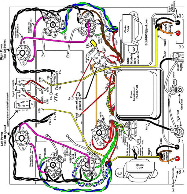
4 8. Mount the first C-354 choke and the SCM on the RIGHT side of the chassis with two 8-32 screws and matching kep nuts. The SCM (not seen on the pictorial but seen in color photo) is attached under the left screw and nut. Make sure that the two choke leads and the wire from pin 4 of the SCM face towards the FRONT of the chassis. 9. Mount the THREE lug terminal strip on the LEFT side of the chassis with a single 4-40 screw and kep nut as shown on the pictorial. Use the screw hole closest to the power transformer. 10. Mount the RIGHT A output transformer with 8-32 hardware. The side of the transformer with the YELLOW-ORANGE-BROWN-BLACK leads must face the BACK of the amp. Mount the LEFT output transformer and fit the SECOND C-354 choke under the far left nut closest to the FRONT of the chassis. NOTE This choke mounts with just that ONE nut and screw. The two wires on the choke should face the INSIDE of the chassis. Check the pictorial and/or photo. 11. Mount the quadruple section filter capacitor in the special cutout. It is IMPORTANT that the quad cap be properly oriented. The 80 Mfd SECTION which is designated with a HALF CIRCLE symbol must face the BACK of the amp. Fasten by twisting each of the four mounting tabs one-quarter turn. 12. Mount the ONE LUG terminal strip in the hole just to the left of the quad cap. This will be your main grounding point for the entire amp. The original amp had two grounding tabs as is seen in the pictorial. 13. Please refer to the triode/pentode pictorial for installing the triode/pentode switches. Obtain the two non shorting DPDT switches from the triode/pentode kit bag. Install the switches in the two chassis holes where the original Dynaco ST-70 bias controls use to be. These two 3/8 holes are not shown on the main pictorial. The switches are a loose fit in the holes and must be centered in the hole before they are tightened. 14. Remove the outside nut and larger flat washer from the switch. The smaller flat washer goes against the INSIDE of the chassis. Place the larger flat washer on the chassis TOP and nut on top of the flat washer. On the inside of the chassis make sure that the six terminals on the switch face from the front to the back of the amp so that the switch toggle on the top may be switched from FRONT to BACK and not side to side. Again refer to the triode/pentode pictorial 15. Center the two switches in the holes and tighten the nuts lightly with square nosed slipjoint pliers. Check alignment of the two switches. If alignment is not correct move the switches slightly until alignment is correct. Make your final tightening but DO NOT OVERTIGHTEN THIS NUT OR YOU WILL BREAK THE SWITCH 16. Mount the two TWO lug terminal strips back to back in the single central 4-40 hole between the two triode/pentode switches. Try to keep the strips straight and parallel to the sides of the amp as you tighten the screw. Check the color photo. 17. NOTE At this time DO NOT MOUNT the two front power takeoff sockets, the front slide switch which fits into the stereo/mono slot or the input jacks. These three items must be mounted after installation of the VTA driver board. WIRING Each length of hookup wire specified should have approximately ¼ inch of insulation stripped from each end unless otherwise specified. Wires from the three transformers should be shortened appropriately to the correct length to reach their terminal point. Again, as with the original Dynaco manual, if you see the symbol (S) this means to solder that connection at that time. If the symbol is not there DO NOT SOLDER that connection at that time. The 20 gauge solid core copper wire supplied with this kit is the recommended wire to use. Only rosin core solder is recommended for soldering. Always make a solid mechanical connection with your pliers to the terminal point before soldering. Always keep the chassis and transformers on a soft surface like a towel so they won t get scratched. Orient the chassis so that the power transformer is towards you. Oriented this way the, the LEFT channel is on your LEFT and the RIGHT channel is on your RIGHT.
5 1. Twist the pair of WHITE leads from the power transformer together and dress to socket V1. Connect one lead to pin #2 of V1 (S) and one lead to pin #8 of V1. NOTE These leads are yellow on the color photograph. 2. Twist the pair of RED leads from the power transformer together and dress to socket V1. Connect one lead to pin # 4 of V1 (S). Connect the other lead to pin # 6 of V1 (S) 3. Twist the pair of GREEN leads from the power transformer together and dress to socket V2. Connect one green lead to pin # 2 of V2 and one green lead to pin # 7 of V2. 4. Twist the pair of BROWN leads from the power transformer together and dress to socket V7. Connect one brown lead to pin #2 of V7 and the other brown lead to pin #7 of V7. 5. Twist the BROWN/YELLOW and GREEN/YELLOW wires from the power transformer and dress to the 3 lug terminal strip. Connect the BROWN/YELLOW lead to lug # 3 - the lug closest to the power transformer. Connect the GREEN/YELLOW wire to lug # 1 the lug furthest from the power transformer. 6. Connect the RED/YELLOW lead to the one lug terminal strip next to the quad cap filter capacitor. 7. Dress the RED lead from the LEFT OUTPUT TRANSFORMER and the RED lead from the RIGHT OUTPUT TRANSFORMER to the 80 Mfd terminal on the QUAD CAP having the HALF CIRCLE symbol. This is the terminal that faces the REAR of the amp. 8. Shorten (if necessary) and connect the 4 inch wire from lug 4 of the Supplementary Cap Module (SCM) to the same 80 Mfd terminal on the quad cap having the HALF CIRCLE symbol as described in the step above. 9. Twist together the two CHOKE leads from right side choke. Connect one choke lead to 80 Mfd terminal on the quad cap having the HALF CIRCLE symbol and the other choke lead to the 40 Mfd terminal on the quad cap having the SQUARE symbol. Twist together and connect the two choke leads from the choke that is mounted on the left side of the chassis to the same 80 and 40 Mfd terminals on the quad cap. You MAY have to lengthen the two leads from the second choke slightly by adding 2 or 3 inches of wire to each lead. If you have to lengthen these leads be sure to insulate the connection with black electrical tape or Teflon shrink tubing. 10. Dress the two BLACK leads from the power transformer around the power transformer as shown in the pictorial. Connect one BLACK lead to lug A of the fuse post (S) and one BLACK lead to lug # 1 of the on/off switch (S). INCOMPLETE MANUAL ST-120 voltage readings
6 * Note # 1 Make sure you have your meter set to AC or DC as mentioned below. Ground is any point on the chassis frame. Place the black or negative probe on the chassis and the red or positive probe on the point mentioned. All tubes should be plugged in, inputs shorted or connected to your preamp, speakers connected and no signal should be running through the amplifier. Be careful not to cross two pins with the positive probe! * Note # 2 Readings very slightly above or very slightly below the range are not normally a sign of a problem. Line voltages vary slightly throughout the country. Differences in the rectifier can cause variations also. Weber Copper Cap or a GZ34 Pin 4 to ground volts AC Pin 6 to ground volts AC Any 6550/KT88 Pin 1 to ground approx.550 volts DC (depends on bias setting) Across pins 2 and volts AC Pin 3 to ground volts DC Pin 4 to ground volts DC Pin 5 to ground minus 50 to minus 60 volts DC Pin 6 to ground minus 50 to minus 60 volts DC Pin 8 to ground approx.550 volts DC (depends on bias setting) Quad cap Section # 1 (SQUARE symbol) volts DC Section # 2 (HALF CIRCLE symbol) volts DC Section # 3 (NO symbol) volts DC Section # 4 (TRANGLE symbol) volts DC Central 12AT7 Pin 1 or pin 6 to ground > volts DC Two outer 12AT7 s Pin 1 or pin 6 to ground > volts DC Any 12AT7 across the two incoming heater wires > volts AC -50 VAC on driver board > B+ on driver board > G on driver board > 0 volts AC or DC
7 Triode/Pentode switch pictorial NOTE: Disregard any pin number markings on the switches themselves and use the pin numbers listed below
8
9
DYNACO STEREO 120 C7 REPLACEMENT MANUAL
 DYNACO STEREO 120 C7 REPLACEMENT MANUAL 2013 AkitikA, LLC All rights reserved Revision 1p03 April 29, 2013 Page 1 of 15 Table of Contents Section 1: About This Manual... 3 Who Should Attempt this Project?...
Dynaco ST-70 & Mark 2/3 Quad-Cap / Power Supply Module Below Chassis Version
 Page 1 CAE QUAD Cap Replacement Module PC-S7U-B & PC-S7U-B-M3 Rev3, 2-11 I. Introduction Thank you for choosing our ST-70 & Mark 2/3 Quad Electrolytic Capacitor & Power Supply Replacement Board. It is
Mableaudio Company limited
 Mableaudio Company limited Web: www.mableaudio.com [5E3 assembly manual] Tel:0086-755-83996326 fax:0086-755-83996326 Contact: Ms Mable mable@mableaudio.com WARNING! This amp operates at voltages that may
SCA-80(Q) C11 REPLACEMENT ASSEMBLY MANUAL
 C11 REPLACEMENT ASSEMBLY MANUAL") SCA-80(Q) C11 REPLACEMENT ASSEMBLY MANUAL 2014-2016 AkitikA, LLC All rights reserved Revision 1p05 July 3, 2016 Page 1 of 15 Table of Contents Table of Contents... 2 Table of Figures... 2 Section 1: About
SCA-80(Q) C11 REPLACEMENT ASSEMBLY MANUAL 2014-2016 AkitikA, LLC All rights reserved Revision 1p05 July 3, 2016 Page 1 of 15 Table of Contents Table of Contents... 2 Table of Figures... 2 Section 1: About
Assembly Instructions MP-P2 Power Supply and Chassis Base Plate
 Assembly Instructions MP-P2 Power Supply and Chassis Base Plate The MP-P2 Power Supply is the supply designed to power the mother board and its complement of plug-on boards including the MP-09 Microprocessor
Kit1 300B Edition. Single Ended Triode 8 Watt. Construction Manual & User Guide Volume One
 Kit1 300B 2014 Edition Single Ended Triode 8 Watt Construction Manual & User Guide Volume One Contents Section 1: Receiving your kit...2 Section 2: The Mechanical section Preparation... 3 Tang Strips...
WIRING THE HEATER POWER SUPPLY
 WIRING THE HEATER POWER SUPPLY Fig. 14 13/14 Take the longer PS board (with the 47R resistors and the fuse) and, using M3x6 screws, fix it to the chassis to the left of the mains transformer. The diodes
White Light CLASSIC PEDAL KIT. Assembly Instructions WHEN YOU CAN T BUY IT BUILD IT. StewMac RARE / VINTAGE / HARD TO GET
 Sheet #i-2206 Updated 5/18 StewMac White Light CLASSIC PEDAL KIT Kit case is unpainted IN COLLABORATION WITH EarthQuakerDevices Assembly Instructions The White Light Overdrive is based on vintage overdrives
PAT-4 TOROIDAL TRANSFORMER ASSEMBLY MANUAL
 PAT-4 TOROIDAL TRANSFORMER ASSEMBLY MANUAL 2015 AkitikA, LLC All rights reserved Revision 1p3 August 22, 2015 Page 1 of 13 Table of Contents Table of Contents... 2 Table of Figures... 2 Section 1: About
MOD 102+ GUITAR AMP KIT (K-MOD102+)
") MOD 102+ GUITAR AMP KIT (K-MOD102+) ON BASS 4 6 TREBLE 4 6 VOLUME 4 6 7 7 7 STBY OFF STBY 2 8 MOD 102+ TUBE AMP KIT 1 9 modkitsdiy.com 0 10 Pull-MID BOOST 2 8 1 9 0 10 Pull-BRIGHT 2 8 1 9 0 10 Pull-TURBO
MOD 102+ GUITAR AMP KIT (K-MOD102+) ON BASS 4 6 TREBLE 4 6 VOLUME 4 6 7 7 7 STBY OFF STBY 2 8 MOD 102+ TUBE AMP KIT 1 9 modkitsdiy.com 0 10 Pull-MID BOOST 2 8 1 9 0 10 Pull-BRIGHT 2 8 1 9 0 10 Pull-TURBO
EE-101 ASSEMBLY MANUAL
 EE-101 ASSEMBLY MANUAL 2018 AkitikA LLC All rights reserved Revision 1p07 July 22, 2018 Page 1 of 28 Table of Contents Table of Contents... 2 Table of Figures... 3 Section 1: About This Manual... 4 Who
MOD 102 GUITAR AMP KIT (K-MOD102)
") MOD 0 GUITAR AMP KIT (K-MOD0) ON BASS TREBLE VOLUME MOD 0 TUBE AMP KIT 0 0 0 0 0 0 OFF Use these instructions to learn: How to build a tube amp. This tube guitar amplifier circuit is based on a classic
MOD 0 GUITAR AMP KIT (K-MOD0) ON BASS TREBLE VOLUME MOD 0 TUBE AMP KIT 0 0 0 0 0 0 OFF Use these instructions to learn: How to build a tube amp. This tube guitar amplifier circuit is based on a classic
CLASSIC PEDAL KIT. Assembly Instructions WHEN YOU CAN T BUY IT BUILD IT. StewMac Monarch RARE / VINTAGE / HARD TO GET
 Sheet #i-2205 Updated 2/8 StewMac Monarch CLASSIC PEDAL KIT Kit case is unpainted IN COLLABORATION WITH EarthQuakerDevices Assembly Instructions The Monarch Overdrive is an all discrete, FET-based dirt
BLUE LIGHT FOR DYNACO STEREO 120, SCA-80, OR PAT-4 ROCKER SWITCHES
 BLUE LIGHT FOR DYNACO STEREO 120, SCA-80, OR PAT-4 ROCKER SWITCHES 2014 AkitikA, LLC All rights reserved Revision 1p5 April 8, 2014 Page 1 of 16 Table of Contents Table of Contents... 2 Table of Figures...
Ceramic Tube Sockets & Power Relay for the Collins 516F-2 Collins Radio Association
 Ceramic Tube Sockets & Power Relay for the Collins 516F-2 Collins Radio Association Stu Martin, K2QDE November 2005 Ceramic Tube Socket & Power Relay for the Collins 516F-2 The Collins 516F-2 power supply
Audio Regenesis. Power Supply Capacitor Replacement Board. Dynaco PAS 2, 3, 3X Preamplifiers. Installation Guide. For. Pacific Audio Regenesis
 Audio Regenesis Power Supply Capacitor Replacement Board For Dynaco PAS 2, 3, 3X Preamplifiers Installation Guide Pacific Audio Regenesis www.audioregenesis.com Thank you for choosing our power supply
BLUE LIGHT FOR DYNACO STEREO 120 OR PAT-4 ROCKER SWITCHES
 BLUE LIGHT FOR DYNACO STEREO 120 OR PAT-4 ROCKER SWITCHES 2012 AkitikA, LLC All rights reserved Revision 1p3 April 18, 2012 Page 1 of 15 Table of Contents Table of Contents... 2 Table of Figures... 2 Section
X-Type w/ non-premium sound amplifier installation instructions
 X-Type w/ non-premium sound amplifier installation instructions 1. Pull radio from dash (see Radio Removal Instructions ) 2. Disconnect wiring harness from back of radio by pushing in tab on plug and pulling
ASSEMBLY INSTRUCTIONS FOR NEW FK109 4 LED Railroad Crossing Flasher Kit WITH ADJUSTABLE FLASHING SPEED CONTROL with 4 Red 3mm Leds
 ASSEMBLY INSTRUCTIONS FOR NEW FK109 4 LED Railroad Crossing Flasher Kit WITH ADJUSTABLE FLASHING SPEED CONTROL with 4 Red 3mm Leds Description: Very easy to build, The FK109 Led Flasher kit makes the perfect
k" or #8 nut driver A pair of regular pliers can substitute for the nut drivers but will
 Page of 3 ARIES SYSTEM 300 MUSIC SYNTHESIZER Module AR-38 STEREO REVERB & OUTPUT ASSEMBLY INSTRUCTIONS The previous pages were written as a general guide to familiarize the builder with the components.
Harbach Soft Key (sk-220) Installation Instructions for the Heathkit SB-220
 Installation Instructions for the Heathkit SB-220") Harbach Soft Key (sk-220) Installation Instructions for the Heathkit SB-220 Step-by-Step Instructions with Photos Based on an install by W4HDM Installation & Photos by W4HDM Instructions from http://www.harbachelectronics.com/
Harbach Soft Key (sk-220) Installation Instructions for the Heathkit SB-220 Step-by-Step Instructions with Photos Based on an install by W4HDM Installation & Photos by W4HDM Instructions from http://www.harbachelectronics.com/
Handyman Motor Capacitor Meter PART NO
 Handyman Motor Capacitor Meter PART NO. 2225174 To test a motor-run capacitor in the field with no capacitance meter at hand, you had to hook up the capacitor through an extension cable to a 120V wall
350 Watt Vacuum Tube Amplifier. Owner s Manual
 350 Watt Vacuum Tube Amplifier Owner s Manual CIRCUIT DESCRIPTION The input stage consists of a 12AX7 current sourced long-tailed balanced pair, which is direct coupled to a second long-tailed balanced
QRPGuys Digital RF Probe
 QRPGuys Digital RF Probe First, familiarize yourself with the parts and check for all the components. If a part is missing, please contact us and we will send one. This kit contains seventeen 1206 size
FITTING THE RELAY SWITCH BOARD FITTING THE INPUT SELECTOR SWITCH
 FITTING THE RELAY SWITCH BOARD Fit M3 x 12mm spacers to the COMPONENT side of the board. Use fibre washers under M3 screws on the SOLDER side of the board to avoid grounding the tracks. Push the completed
Arlo Power Distribution Board Kit Rev B (#28996)
") Web Site: www.parallax.com Forums: forums.parallax.com Sales: sales@parallax.com Technical: support@parallax.com Office: (916) 624-8333 Fax: (916) 624-8003 Sales: (888) 512-1024 Tech Support: (888) 997-8267
Web Site: www.parallax.com Forums: forums.parallax.com Sales: sales@parallax.com Technical: support@parallax.com Office: (916) 624-8333 Fax: (916) 624-8003 Sales: (888) 512-1024 Tech Support: (888) 997-8267
General Purpose Flasher Circuit
 General Purpose Flasher Circuit By David King Background Flashing lights can be found in many locations in our neighbourhoods, from the flashing red light over a stop sign, a yellow warning light located
Assembly Instructions
 Assembly Instructions Part Number Description Model Approx. Assembly Time 99994-0903 Windshield Wiper Kit Mule SX 1 Hour WARNING Improper installation of this accessory could result in an accident causing
Arlo Power Distribution Board Kit Rev B (#28996)
") Web Site: www.parallax.com Forums: forums.parallax.com Sales: sales@parallax.com Technical: support@parallax.com Office: (916) 624-8333 Fax: (916) 624-8003 Sales: (888) 512-1024 Tech Support: (888) 997-8267
Web Site: www.parallax.com Forums: forums.parallax.com Sales: sales@parallax.com Technical: support@parallax.com Office: (916) 624-8333 Fax: (916) 624-8003 Sales: (888) 512-1024 Tech Support: (888) 997-8267
Application Note. Walthers/Proto 2000 E7A Tsunami Digital Sound Decoder Installation Notes
 Application Note Overview This application note describes how to install a TSU-1000 digital sound decoder into a Walthers/ Proto 2000 E7A. Skill Level 2: The entire installation can be completed in one
Prusa i3 Printer Assembly Guide
 Prusa i3 Printer Assembly Guide Special thanks to Carlos Sanchez and Miguel Sanchez for the graphics. All graphics captured from their great animation: http://www.carlos-sanchez.com/ Prusa3/ For copyright
ALL AMERICAN. CLASSIC PEDAL KIT Assembly Instructions. StewMac
 heet #i-2153 Updated 12/17 tewmac ALL AMERICAN CLAIC PEDAL KI Assembly Instructions he ALL-AMERICAN is one of the great stompboxes from JH, makers of high-end effects pedals. Whenever JH adds a new pedal
JHS 808. CLASSIC PEDAL KIT Assembly Instructions. StewMac
 heet #i-2150 Updated 12/17 tewmac JH 808 CLAIC PEDAL KI Assembly Instructions he JH808 is one of the great stompboxes from JH, makers of high-end effects pedals. Whenever JH adds a new pedal to their line,
APPENDIX B SPECIFICATION FOR GENERATOR OVERHAUL EMD MODEL AR10 D18... B-1
 Table of Contents APPENDIX B SPECIFICATION FOR GENERATOR OVERHAUL EMD MODEL AR10 D18... B-1 B.01 SCOPE... B-1 B.02 GENERAL... B-1 B.03 ELECTRICAL QUALIFICATION... B-1 B.04 EQUIPMENT RECONDITIONING... B-2
Biasing the Vintage Series (Nomad, BelAir, VT50, Vintage 33)
") Biasing the Vintage Series (Nomad, BelAir, VT50, Vintage 33) This chapter will outline and guide you through the procedures of biasing the Vintage series amplifier. The procedures are broken down in a
Biasing the Vintage Series (Nomad, BelAir, VT50, Vintage 33) This chapter will outline and guide you through the procedures of biasing the Vintage series amplifier. The procedures are broken down in a
SSUTAYU15. Designed for 2015 and newer Chevrolet Tahoe/Suburban and GMC Yukon/Yukon XL vehicles
 SSUTAYU15 Designed for 2015 and newer Chevrolet Tahoe/Suburban and GMC Yukon/Yukon XL vehicles Subwoofer Assembly Subwoofer Harness Subwoofer Power Harness 2018 Stillwater Designs SSUTAYU15-20180313 Wire
PM-200 POWER SUPPLY MODULE v3.2 ASSEMBLY & INSTALLATION INSTRUCTIONS
 PM-200 POWER SUPPLY MODULE v3.2 ASSEMBLY & INSTALLATION INSTRUCTIONS WARNING: Voltages inside the amplifier CAN & WILL KILL YOU! You MUST know how to work around HIGH VOLTAGE safely. If you do not, get
455 khz ( ) Connect the lead from the banded end of the
 Connect the lead from the banded end of the") 455 khz ( ) Connect the lead from the banded end of the Varicap diode (#56-49) to lug 1 (NS) and the other lead to lug 2 (NS) of oscillator coil L3. Refer to Pictorial 10 for the following steps. ( ) Connect
455 khz ( ) Connect the lead from the banded end of the Varicap diode (#56-49) to lug 1 (NS) and the other lead to lug 2 (NS) of oscillator coil L3. Refer to Pictorial 10 for the following steps. ( ) Connect
3 Slot Payphone Controller
 S Coin Controller 2A Information on your Telephone For Your Records Manufacturer Date of Original Manufacture Drawing Reference One of the original patents --- US 2,043,201 This Telephone is Property of
Norcal Power/SWR Meter Assembly & Operating Manual. Revision 1D 10/15/2008
 Norcal Power/SWR Meter Assembly & Operating Manual Revision 1D 10/15/2008 Copyright 2008 NorCal QRP Club Page 1 of 21 Contents CONTENTS...2 INTRODUCTION...3 SPECIFICATIONS...3 ASSEMBLY...4 OPERATING GUIDE...15
METROLOGIC INSTRUMENTS, INC. MX001 Industrial Control Interface Installation and User s Guide
 METROLOGIC INSTRUMENTS, INC. MX001 Industrial Control Interface Installation and User s Guide Copyright 2007 by Metrologic Instruments, Inc. All rights reserved. No part of this work may be reproduced,
STARTER SYSTEM TESTING 5.6
 STARTER SYSTEM TESTING 5.6 ON-MOTORCYCLE TESTS Starter Relay Test NOTE Starter relay test also applies to ignition and key switch relays.. See Figure 5-5. Locate starter relay. The relay is attached to
An ISO 9001 Company. BOP 1KW-MG FIRMWARE RETROFIT KIT
 INSTRUCTION MANUAL 1. DESCRIPTION KEPCO An ISO 9001 Company. BOP 1KW-MG FIRMWARE RETROFIT KIT BOP 1KW-MG RETROFIT KIT 219-0562 Kepco KIT 219-0562 contains the PROMs used to upgrade the firmware for BOP
In this installment we will look at a number of things that you can do with LEDs on your layout. These will include:
 Introduction The first article in this series, LEDs 101 - The Basics, served to review the characteristics and use of LED lighting in a garden railway environment. It also generated a host of questions
Disaster Transport CLASSIC PEDAL KIT. Assembly Instructions WHEN YOU CAN T BUY IT BUILD IT. StewMac RARE / VINTAGE / HARD TO GET
 StewMac Sheet #i-2203 Updated 5/8 Disaster Transport CLASSIC PEDAL KIT Kit case is unpainted IN COLLABORATION WITH EarthQuakerDevices Assembly Instructions The Disaster Transport is an analog voiced digital
Replacement Tach Board Manual
 Replacement Tach Board Manual 67-74 Dodge and Plymouth Cars that use electronics Internal to the tachometer. Real Time Engineering 19352 Hilton Rd. Springdale, AR 72764 (479) 756-3917 fax Rev8 www.rt-eng.com
2011 Honda Accord Coupe Fine Mesh Grille
 IMPORTANT: PLEASE KEEP THIS INSTRUCTION MANUAL FOR FUTURE REFERENCE! TOOLS REQUIRED 2011 Honda Accord Coupe Fine Mesh Grille Replacement Upper / Lower Overlay Part #: Complete #1124-0102-11 / Black Ice
GVW AGM Auxiliary Battery Kit for Air-cooled Westfalia Campers and all Vanagon NON-campers
 GVW-253-701AGM Auxiliary Battery Kit for 1980-1983 Air-cooled Westfalia Campers and all Vanagon NON-campers The purpose of this kit is to add an Interstate SLA1161 battery as an auxiliary battery under
PONTIAC FIREBIRD
 1974-78 PONTIAC FIREBIRD Two Panel Sequential LED Tail Light Kit Installation Guide Kit Contents: 2 LED panels 2 LED panel mount kits 6 rubber grommets 1 power wire 1 pigtail harness Kit 1 crimp terminal
Operation and Installation Manual
 Operation and Installation Manual G-Scale Graphics 5860 Crooked Stick Dr. Windsor, CO 80550 970-581-3567 GScaleGraphics@comcast.net www.gscalegraphics.net Revision A: Updated 2/7/2018 Page Overview The
SS & SS SOFT-START v3.0 ASSEMBLY & INSTALLATION INSTRUCTIONS
 SS-221-120 & SS-221-240 SOFT-START v3.0 ASSEMBLY & INSTALLATION INSTRUCTIONS WARNING: Voltages inside the amplifier CAN & WILL KILL YOU! You MUST know how to work around HIGH VOLTAGE safely. If you do
SWRA211. T-TAP x2 10MM BOLT FUSE WIRE TIES x6 SUBWOOFER ASSEMBLY 200 WATT AMP BRACKET ASSEMBLY POWER HARNESS OVERLAY HARNESS.
 SWRA211 Designed for 2011-2014 Jeep Wrangler two door with base audio or premium audio T-TAP x2 10MM BOLT FUSE WIRE TIES x6 SUBWOOFER ASSEMBLY 200 WATT AMP BRACKET ASSEMBLY POWER HARNESS 2012 Stillwater
VOX AC4tv Mercury Studio-Pro Upgrade Kit 21. Detail of the 15KΩ resistor in series with. as they appear in the Upgraded amp in location R23.
 Detail of the 5KΩ resistor in series with the.kω resistor as they appear in the Upgraded amp in location R. Detail of the.7ηf in series with the 0KΩ carbon comp resistor as they appear in the Upgraded
Broadway Limited (and Blueline) SD40-2 Tsunami Digital Sound Decoder Installation Notes
 SD40-2 Tsunami Digital Sound Decoder Installation Notes") Broadway Limited (and Blueline) SD40-2 Tsunami Digital Sound Decoder Installation Notes Overview This application note describes how to install a TSU-AT1000 digital sound decoder into a HO Broadway Limited
Broadway Limited (and Blueline) SD40-2 Tsunami Digital Sound Decoder Installation Notes Overview This application note describes how to install a TSU-AT1000 digital sound decoder into a HO Broadway Limited
3143 Production Drive Fairfeild, Ohio Model HA Installation and Service Manual
 3143 Production Drive Fairfeild, Ohio 45014 513-874-3733 Model HA-1000 Installation and Service Manual 3143 Production Drive Fairfeild, Ohio 45014 513-874-3733 Model HA-1000 Installation and Service Manual
Amp & Speaker Upgrade Install Instructions for Victory Cross Country
 Amp & Speaker Upgrade Install Instructions for Victory Cross Country Tools Needed: 13mm Socket 4mm Ball Head Allen Socket 5mm Allen Wrench 10mm Wrench Wire Cutters Wire Strippers Phillips Screwdriver Pocket
CTB-16K Hobbyist Line Kit 40 Amp 16 Channel Light Controller Assembly Manual *** Preliminary ***
 CTB-16K Hobbyist Line Kit 40 Amp 16 Channel Light Controller Assembly Manual *** Preliminary *** Version 1.0 January 12, 2006 Copyright Light O Rama, Inc. 2006 Table of Contents 1 Introduction... 3 2 Required
Installation Instructions Harley-Davidson Saddlebag Lids
 Installation Instructions Harley-Davidson Saddlebag Lids Thank you for your purchase of Bagger Audio Saddlebag Lids for your Harley- Davidson motorcycle. We have carefully engineered these products to
65 P-REVERB 15W COMBO AMP KIT. Sparkling bright, perfect for the surf. ORIGINAL AA1164 CIRCUIT ASSEMBLY INSTRUCTIONS. With loads of helpful tips!
 P- W COMBO AMP KIT ORIGINAL AA CIRCUIT Sparkling bright, perfect for the surf. ASSEMBLY INSTRUCTIONS With loads of helpful tips! Contents About this iconic amp... How to build this kit!... Parts list....
Build Your Own Clone Classic Brit 50 Kit Instructions (Revision 1.0)
") Build Your Own Clone Classic Brit 50 Kit Instructions (Revision 1.0) WARNING!!! HIGH VOLTAGE!!!! Tube amplifiers contain high voltage that can cause injury and even death. Please use extreme caution and
Build Your Own Clone Classic Brit 50 Kit Instructions (Revision 1.0) WARNING!!! HIGH VOLTAGE!!!! Tube amplifiers contain high voltage that can cause injury and even death. Please use extreme caution and
HARNESS KIT 3 PORT ISOLATION MODULE LIGHT SYSTEM. Parts List and Installation Instructions CAUTION
 May 1, 2018 Lit. No. 92991, Rev. 00 HARNESS KIT 3 PORT ISOLATION MODULE LIGHT SYSTEM Parts List and Installation Instructions Read this document before installing the snowplow. See your sales outlet/website
Shelby GT500 Front Fascia Conversion Kit (05-09 All) Item # Installation Time: 1 Day. Required tools:
 Item # Installation Time: 1 Day. Required tools:") Shelby GT500 Front Fascia Conversion Kit (05-09 All) Item #53611 Installation Time: 1 Day Required tools: Phillips Screw driver 10mm Socket + Ratchet/Wrench 8mm Socket + Ratchet/Wrench 5mm Socket + Ratchet/Wrench
Shelby GT500 Front Fascia Conversion Kit (05-09 All) Item #53611 Installation Time: 1 Day Required tools: Phillips Screw driver 10mm Socket + Ratchet/Wrench 8mm Socket + Ratchet/Wrench 5mm Socket + Ratchet/Wrench
ARDUINO 2WD SMART ROBOT CAR KIT
 EN ARDUINO 2WD SMART ROBOT CAR KIT P a g e 2 PARTS LIST Please make sure that the following pieces are included in your kit Component Quantity Remarks Arduino Sensor Shield v5.0 1 Align pins using needle
CHEVY CAMARO Four panel Sequential LED Taillight kit installation guide
 1978-81 CHEVY CAMARO Four panel Sequential LED Taillight kit installation guide Kit Contents: 4 LED panels 1 power wire with t-tap 2 driver side LED harnesses, 24 2 passenger side LED harnesses, 48 4 LED
P Original Series Cargo Van Lift Mounting Instructions Fullsize Ford Van present. Preparing the Gate
 Fullsize Ford Van- 1992-present Preparing the Gate 1. Remove the mounting hardware which is banded to the liftgate. 2. Verify mounting kit (Figure 1 and Table 1). S-400-40 STRAP VAN MOUNTING EAR BENT BRACKET
Soldering Pi2Go Lite. Soldering the Line-Follower PCB
 Soldering Pi2Go Lite First check which version of the main PCB you have. It is marked above the left motor "Pi2Go-Lite v1.x". There are minor changes to some parts of the build. v1.0 (initial release)
Tip: and Orient Express LED Light Upgrade Date: Correction
 Hi All, I have since inherited my friend Rudolf s 42755 Orient Express with the extra 42760 car set and wanted to complete the LED light upgrade as we had planned. Side view of the Restaurant car with
Manual Version November 2011
 Manual Version 2.2 - November 2011 This Version supports the latest Interstage version using the T-195 Mains TX CH-170 220uf 4 pole cap New POWER SUPPLY wiring strategy Copper Insert plate and CMC valve
Instructions for Front Midrange / Tweeter Installation in BMW 3 Series/M3 (E36)
") Disclaimer: Bavarian Soundwerks highly recommends professional installation of the products we sell. We provide these installation instructions free of charge as a guide to assist those customers who choose
Disclaimer: Bavarian Soundwerks highly recommends professional installation of the products we sell. We provide these installation instructions free of charge as a guide to assist those customers who choose
RS-2 SINGLE ACTION REAR BUMPER WITH TIRE CARRIER INSTALL MANUAL FOR JEEP WRANGLER ALL MODELS.
 RS-2 SINGLE ACTION REAR BUMPER WITH TIRE CARRIER INSTALL MANUAL FOR 2007-2016 JEEP WRANGLER ALL MODELS. Rear Bumper Installation Instructions 1) Remove factory rear bumper, (this includes all tow hitch
Hasse Mods for the Ampeg J20 Guitar Amp
 Hasse Mods for the Ampeg J20 Guitar Amp The following is adapted from a post I put up on The Gear Page, in the Amp Techincal forum. It shows the mods I did to my Ampeg J20. Okay, here s my mods for this
10260 Retrofit to 10260A Non-Contact Sensor Instructions Kits through -512
 10260 Retrofit to 10260A Non-Contact Sensor Instructions Kits 51404974-501 through -512 Document Number Form: 62-86-33-16D Effective: 3-1-01 Supersedes: 11-00 Summary Retrofitting your 10260 actuator from
Installation Instructions and Suggestions For Jeep YJ Fiberglass Replacement Bodies
 Installation Instructions and Suggestions For Jeep YJ Fiberglass Replacement Bodies Getting started with the removal of your existing Jeep body. Trust nothing to memory; take photos of everything at different
3D PRINTER. Pack 09. Anything you can imagine, you can make! 3D technology is now available for you at home! BUILD YOUR OWN
 BUILD YOUR OWN Pack 09 Anything you can imagine, you can make! 3D PRINTER Compatible with Windows 7 & 8 Mac OS X 3D technology is now available for you at home! www.model-space.com BUILD YOUR OWN 3D PRINTER
MacBook Unibody Model A1278 LVDS Display Cable Replacement
 MacBook Unibody Model A1278 LVDS Display Cable Replacement Replace the LVDS display cable in your MacBook Unibody Model A1278. Written By: Walter Galan ifixit CC BY-NC-SA www.ifixit.com Page 1 of 28 INTRODUCTION
VECTRIX VX-2 SERVICE MANUAL. Version 1.0/May 2011 VECTRIX, LLC
 www.vectrix.com CONTENTS SECTION A: Tools 1 Tools Needed SECTION B: Mechanical Parts 1 Front Fairing 2 Front Console Cover 3 Speedometer Cover 4 Front Vertical Panel Cover-Lower 5 Front Vertical Panel
Detroit Speed, Inc. Electric Headlight Door Kit Corvette P/N: &
 Detroit Speed, Inc. Electric Headlight Door Kit 1968-82 Corvette P/N: 122006 & 122007 The Detroit Speed Inc. Electric Headlight Door Kit replaces the stock vacuum actuated system on all 1968-82 Corvettes.
CHAPTER 1 - INTRODUCTION
 CHAPTER 1 - INTRODUCTION a. about the 300BSE series amplifier The 300BSE series kit amplifier, features the classic 300B valve in single ended configuration. It is available in two versions, the 300BSEi
AUXILIARY BATTERY BOX INSTALLATION INSTRUCTIONS
 AUXILIARY BATTERY BOX INSTALLATION INSTRUCTIONS The original TOMMY GATE hydraulic lift Assembling the Auxiliary Battery Box 1. Remove the cover from the auxiliary battery box by removing the two nuts and
ELECTRICAL SYSTEM UPGRADE
 NEW CONTROLLER & ELECTRICAL SYSTEM UPGRADE FOR DAIRY TECH, INCORPORATED 10, 30 & 60G PASTEURIZERS Parts to Include 2 Wire ties (Nuts) 2 sticky wire mount pads Large Rubber Grommet (for bottom of electric
Designed for 2014 and newer 1500 Series and 2015 and newer Heavy Duty GM Silverado/Sierra Double Cab vehicles
 19303116 Designed for 2014 and newer 1500 Series and 2015 and newer Heavy Duty GM Silverado/Sierra Double Cab vehicles Subwoofer Assembly Subwoofer Body Harness 25A Fuse Wire Ties x 6 Wire Taps x 2 Adapter
WOC & WOC Top & Back Installation Instructions
 Shown with optional Sun Roof WOC-900500-2 & WOC-900501-2 Top & Back Installation Instructions Install Order! Heater Door System Wiper on to Windshield Windshield Rear Panel Top Panel Tools needed: 5/16
Electrical Wiring Practices
 Chapter 2 Electrical Wiring Practices and Diagrams MElec-Ch2-1 Overview Safety Standards Wiring Considerations Wire Terminations Coaxial Cable Wiring Installations Wiring Diagrams MElec-Ch2-2 Safety Lethal
and Original Series Pickup Lift Mounting Instructions Fleetside Chevy & GMC Trucks Fleetside 4-door Chevy & GMC Trucks T-100
 r ve and Original Series Pickup Lift Mounting Instructions Fleetside Chevy & GMC Trucks - 1960-1987 Fleetside 4-door Chevy & GMC Trucks - 1988-1991 Preparing the Gate 1. Remove the mounting hardware which
Important! The subwoofer system is designed to be used only with the rear seat in the up position only.
 Important! The subwoofer system is designed to be used only with the rear seat in the up position only. CONTENTS 1EA. SUBWOOFER ASSEMBLY 2EA. BRACKET LOWER 2EA. BRACKET UPPER 1EA. OVERLAY HARNESS 2EA.
Arlo Power Distribution Board Kit (#28996)
") Web Site: www.parallax.com Forums: forums.parallax.com Sales: sales@parallax.com Technical: support@parallax.com Office: (916) 624-8333 Fax: (916) 624-8003 Sales: (888) 512-1024 Tech Support: (888) 997-8267
Web Site: www.parallax.com Forums: forums.parallax.com Sales: sales@parallax.com Technical: support@parallax.com Office: (916) 624-8333 Fax: (916) 624-8003 Sales: (888) 512-1024 Tech Support: (888) 997-8267
CVO - with ipod Amp & Speaker Upgrade Install Instructions for Batwing Fairing
 CVO - with ipod Amp & Speaker Upgrade Install Instructions for Batwing Fairing Tools Needed: 1/2 inch Socket Wire Cutters 7/16 inch Socket Wire Strippers 5/16 inch Socket Phillips Screwdriver 1/2 inch
LIFT-304 (3 ) and LIFT-104 (6 ) Drop Spindle Lift Kits Yamaha G22, Gas or Electric Installation Instructions
 and LIFT-104 (6 ) Drop Spindle Lift Kits Yamaha G22, Gas or Electric Installation Instructions") LIFT-304 (3 ) and LIFT-104 (6 ) Drop Spindle Lift Kits Yamaha G22, Gas or Electric Installation Instructions LIFT-304 LIFT-104 Contents of LIFT-304/104 Yamaha G22 Lift Kit: a (1 ea.) Passenger Side Spindle
LIFT-304 (3 ) and LIFT-104 (6 ) Drop Spindle Lift Kits Yamaha G22, Gas or Electric Installation Instructions LIFT-304 LIFT-104 Contents of LIFT-304/104 Yamaha G22 Lift Kit: a (1 ea.) Passenger Side Spindle
Application Note. Atlas RS-3 Tsunami Digital Sound Decoder Installation Notes
 Application Note Atlas RS-3 Tsunami Digital Sound Decoder Installation Notes Overview This application note describes how to install a TSU-AT1000 digital sound decoder into an HO Atlas RS-3. Skill Level
Zkit60 Introduction. Finished Zkit60 with cover off, one volume control, built in an Ebay DIY chassis
 Zkit60 Introduction The Zkit60 design was originally done in 1981 by an employee of Audio by VanAlstine, Woodbury MN. Nothing became of it, and the one page, hand drawn schematic sat in a file cabinet
LIFT-507 BMF Lift Kit E-Z-Go RXV Gas or Electric Installation Instructions
 LIFT-507 BMF Lift Kit E-Z-Go RXV Gas or Electric Installation Instructions Contents of LIFT-507 E-Z-Go RXV BMF Lift Kit: a (1 ea.) BMF A-Arm Assembly b (1 ea.) Driver Side Shock Tower c (1 ea.) Passenger
Tri-Spark Ignition System Installation Triple Cylinder TRI-0001
 Tri-Spark Ignition System Installation Triple Cylinder TRI-0001 There are potentially lethal high voltages produced at the ignition coils and spark plugs, therefore every precaution must be taken to prevent
STARTER SYSTEM TESTING 5.6
 STARTER SYSTEM TESTING 5.6 ON-MOTORCYCLE TESTS b088x5x Starter Relay Test NOTE Starter relay test also applies to ignition and key switch relays.. See Figure 5-5. Locate starter relay. The relay is attached
MOD 101 GUITAR AMP KIT (K-MOD101)
") MOD 0 GUITAR AMP KIT (K-MOD0) ON MOD 0 TUE AMP KIT 5 6 7 5 6 7 5 6 7 8 8 8 9 9 9 OFF 0 0 0 0 0 0 POWER STANDY ASS TRELE VOLUME INPUT 5/ 6" Use these instructions to learn: How to build a tube amp. How
MOD 0 GUITAR AMP KIT (K-MOD0) ON MOD 0 TUE AMP KIT 5 6 7 5 6 7 5 6 7 8 8 8 9 9 9 OFF 0 0 0 0 0 0 POWER STANDY ASS TRELE VOLUME INPUT 5/ 6" Use these instructions to learn: How to build a tube amp. How
DVS Cypress Face Installation Instructions (SKU )
") Table of Contents Compatibility... 1 Packing List... 1 Installation... 2 Prepare the Insert for Face Installation... 2 Attach the Surround Panels (if applicable)... 6 Assemble the Face... 7 Attach the
Table of Contents Compatibility... 1 Packing List... 1 Installation... 2 Prepare the Insert for Face Installation... 2 Attach the Surround Panels (if applicable)... 6 Assemble the Face... 7 Attach the
DVL Cypress Face Installation Instructions (SKU )
") Table of Contents Compatibility... 1 Packing List... 1 Installation... 2 Prepare the Insert for Face Installation... 2 Assemble the Face... 6 Attach the Surround Panels (if applicable) and Face... 10 Hang
Table of Contents Compatibility... 1 Packing List... 1 Installation... 2 Prepare the Insert for Face Installation... 2 Assemble the Face... 6 Attach the Surround Panels (if applicable) and Face... 10 Hang
EB Conveyor Maintenance Guide
 EB Conveyor Maintenance Guide EN-0037 Rev A EB Conveyor Maintenance Guide www.qdraw.com Table of Contents Overview Page 3 Exploded View Of A Standard EB Conveyor Page 4 Preventative Maintenance Page 5
GVW AGM Auxiliary Battery Kit for Vanagon Westfalia Full Camper
 GVW-253-700AGM Auxiliary Battery Kit for 1983-1991 Vanagon Westfalia Full Camper The purpose of this kit is to add an Interstate SLA1161 as an auxiliary battery under the driver's seat of 1983 to 1991
and Original Series Pickup Lift Mounting Instructions Fullsize Nissan Titan Trucks present T-420 BOLT-ON GUSSET PART#5257
 and Original Series Pickup Lift Mounting Instructions Fullsize Nissan Titan Trucks- 2004-present Preparing the Gate 1. Remove the mounting hardware which is banded to the liftgate. 2. Verify mounting bracket
C15C C15C. Page 1 of 20
 2 x Lid Front Hinge 1135 8 x M8 Bolt 8 x M8 Washer (3mm Thick) 4 x M6 Large washers 4 x M6 Spring washers 4 x M6 x 40mm Bolts 6 x M6 20mm Bolts 6 x M6 Washers 20 x Screws 2 x Lid mount gas strut bracket