Mableaudio Company limited
|
|
|
- Catherine Horn
- 6 years ago
- Views:
Transcription
1 Mableaudio Company limited Web: [5E3 assembly manual] Tel: fax: Contact: Ms Mable WARNING! This amp operates at voltages that may exceed 400V! Use extreme caution when building and testing. If you are not comfortable working with high voltages, refer assembly and testing to a qualified technician. Neither the manufacturer nor the seller of this kit assume any responsibility for damages or injuries incurred during assembly, testing, repair, or usage of this device. Note: There are some minor variations between this 5E3 kit and the original Fender 5E3. Most of these changes improve the noise and hum characteristics, and do not alter the tone or the sound in any way. We have provided a schematic diagram at the end of this document. You can find the original 5E3 schematic on many websites, if you wish to compare the two. Recommended tools: Screwdrivers -- Standard and Philips Adjustable wrench (standard pliers will suffice) Needle Nose Pliers Diagonal Cutters Wire Strippers Soldering Iron to 40 watt or temperature controlled solder station High Power Soldering Iron or Gun 100 watts or more Solder Multimeter -- AC/DC rated for at least 450V DC, resistance Power Drill or Dremel rotary tool with grinder attachment, or a small to medium file


2 Eyelet Board and parts Verify that you have all the necessary parts shown:

 are polarized and need to be placed")
: Pull wires through the")


: Position")

3 Board Assembly Carefully install all parts in the positions shown in the bottom image below. Remember that electrolytic capacitors (22uf/450v and 22uf/25v) are polarized and need to be placed in the direction shown. Eyelet board (shown): Pull wires through the eyelets and solder. Cut excess wire from the other side of the board. To make things easier, you can hold off on soldering until the wires are attached in the next step. Turret board (see third image, top row): Position each component by running wires through the turrets and bend wires as necessary. Remove the component and cut the wires so that only 1/8-1/4in. or 3-6mm is inside the turret. Then reinsert the leads and solder.

.")
 by stripping 3/8in or 9mm from the end of the wire, and then wrap")
4 Circuit Board Wiring Tip: It may be easier to work with wire ends if you tin them first. Strip insulation off the end as needed. Then, heat the wire with your soldering iron and touch solder to the wire just enough so the solder flows into the strands. Don t let the solder blob or glob onto the wire. Solder wires in place as shown. Measure and cut each wire so that it hangs off the board by the specified number of inches (1in = 25.4mm). It s OK if you cut them longer than specified. Excess will be cut off at final assembly. If your board has turrets, attach the wires on the top of the board (component side) by stripping 3/8in or 9mm from the end of the wire, and then wrap the wire around the turret (see image to the right). To solder, hold your soldering iron where it is touching both the wire and the turret until solder flows and solder all the way around where the wire touches the turret.


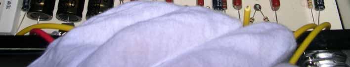
5 Chassis Level assembly Tip: Wear white cloth gloves when handling the chassis to avoid getting fingerprints on the chrome surface. Check to see that all necessary parts are present.


.")

6 Mount the two 9-pin mini sockets in the orientation shown, with the gap between Pin 1 and Pin 9 towards the top of the chassis. Mount four ¼ in. jacks to the front of the chassis at this time as well. Next, twist two green wires together as shown to make the filament wires. Solder one lead to Pin 9, and the other across Pins 4 and 5 of the first preamp tube (12AY7). Your first segment will go from here to Pin 9 and Pins 4 and 5 of the second preamp tube (12AX7). Tip: Tight, consistent twists will make your amp operate quieter. Twist and cut the second segment of green filament wire to go from Pin 9 and Pins 4 and 5 of the second preamp socket (12AX7) to the nearest output tube socket hole. Make sure it is long enough to follow along the lip at the bottom of the chassis.


 as shown. Take a.")

7 Install two ¼ in. jacks into the next two holes in the rear of the chassis. Connect a black wire from Pin 1 on Jack B to Pins 1 and 2 on Jack A. Connect a green wire from Pin 3 on Jack A to Pin 3 on Jack B, Install a potentiometer into the first position (Pot 1) as shown. Take a.0047uf 630V capacitor and bend the leads as shown below. Solder one lead to Pin 1, and leave the other lead along the back of the potentiometer to be soldered later. Solder a short length of yellow wire to Pin 2.


8 Find the other two potentiometers. On each of them, bend Pin 1 back and solder it to the metal casing as shown. Tip: To get solder to stick to a solid metal surface such as the back of a potentiometer, it helps to rough up the surface first. You can do this with a power drill or Dremel tool with a grinding attachment. You can also use a file. Install these potentiometers in the two open positions (Pot 2 and Pot 3) and solder a 470pf capacitor from Pin 3 on Pot 1 to Pin 2 on Pot 2. Use a small piece of tubing, heat shrink, or insulation stripped from a wire to insulate the lead that goes to Pot 2 from touching the grounded lead. Solder the yellow wire from Pin 2 on Pot 1 to Pin 3 on Pot 2. Install two threaded standoffs to the chassis for circuit board mounting


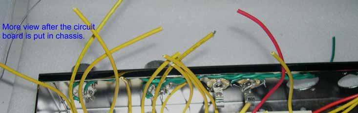
9 Install two rubber grommets for the output transformer wires to pass through Install the output transformer with the green and black leads towards the output jacks. Run the wires through the grommets, and pull them towards the rear of the chassis to keep them out of the way of the circuit board. Note: If you wish, you may hold off on installing the output transformer until later. This will make it easier to complete the next few steps, but it will be more difficult to bolt the transformer down if you do it this way. Make sure that all the wiring on the back side of the circuit board is correct before proceeding to the next step! Any errors made will be extremely difficult to repair after the board is wired in. Before installing the circuit board, make sure that all of the wires are bent upwards, so none of them become buried under the board. Align the two screw holes with the standoffs and carefully screw the board down. Don t force the screws if the board doesn t want to go all the way into place.

10


: Connect")

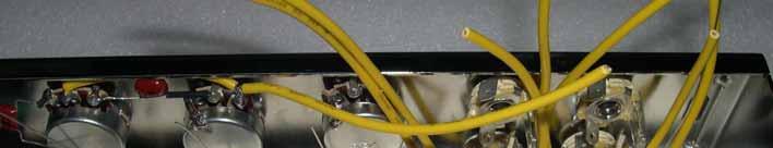
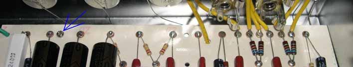
11 First Preamp tube (12AY7): Wire as follows: Point 1 to Pin 8, Point 2 to Pin 2, Point 3 to Pin 7, Point 4 to Pin 1, and Point 5 to Pin 6. Cut off excess wire as needed. Second preamp tube (12AX7): Connect Point 6 to Pin 3, Point 7 to Pin 2, Point 8 to Pin 1, Point 9 to Pin 6, Point 10 to Pin 8, and Point 11 to Pin 7.


12 Overall view of the preamp wiring: Front panel wiring: To solder the ground lead to the chassis, it helps to remove some of the chrome surface using a drill or Dremel tool with a grinder attachment. You can also scrape it off with a screwdriver, a knife, or the edge of a file. Heat the spot with a high power (100+ watt) soldering gun until solder flows and sticks. Then, solder the wire down to the spot.


13 Input Jack Wiring Jack A: Connect Point 1 to Pin 1. Solder a 1 Meg Ohm resistor between Pin 1 and Pin 2. Connect Pins 2 and 3 together. Jack B: Connect Point 2 to Pin 1. Connect Pin 3 to Pin 2 on Jack A. Leave Pin 2 empty. Connect Point 3 to Pin 2 on Pot 3.


14 Jack C: Connect Point 4 to Pin 1. Solder a 1 Meg Ohm resistor between Pin 1 and Pin 2. Connect Pins 2 and 3 together. Jack D: Connect Point 5 to Pin 1. Connect Pin 3 to Pin 2 on Jack C. Leave Pin 2 empty. Connect Point 7 to Pin 3 on Pot 3. Connect Pin 3 on Pot 2 to Pin 3 on Pot 3. Connect Point 6 to Pin 2 on Pot 2.


15 Solder the remaining three bare ground wires to the backs of the three potentiometers: Tip: To get solder to stick to a solid metal surface such as the back of a potentiometer, it helps to rough up the surface first. You can do this with a power drill or Dremel tool with a grinding attachment, or a file. Overall view of the front panel wiring:


16 If you have not done so yet, mount the output transformer to the chassis. Make sure that the black and green wires of the secondary tap are closest to the output jacks. Run the wires through the rubber grommets. Install the three octal tube sockets and tube retainers as shown. Make sure the sockets are turned so that the key notch on the center hole is towards the open bottom of the chassis as shown. Bend the solder lugs on all three sockets outward, away from the sockets.


17 Twist the black and green secondary wires from the output transformer. Connect the black wire to Pin 2 and the green wire to Pin 3 on Jack A.


18 Output tube wiring Connect the twisted green filament wires from the 12AX7 tube to pins 2 and 7 on the first 6V6 tube socket


19 Connect the twisted green filament wires from the first 6V6 tube socket to pins 2 and 7 on the second 6V6 tube socket. Twist together another pair of green wires long enough to go from the second 6V6 socket to the pilot light hole on the front panel. Connect one end to pins 2 and 7 and leave the other end disconnected for now. Connect Point 2 on the circuit board to the Pin 8 on the second 6V6 tube socket. Run a yellow wire from Pin 8 on the first 6V6 tube to Pin 8 on the second 6V6 tube socket.


20 Connect Point 1 on the circuit board to Pin 1 on the first 6V6 tube socket. Connect a red wire from Pin 1 on the first 6V6 tube socket to the Pin 1 on the second 6V6 tube socket. Solder a 470 Ohm 1W resistor between Pin 1 and Pin 4 on both 6V6 tube sockets.


21 Connect the Blue wire from the primary of the OT to Pin 3 on the second 6V6 tube socket. Connect the Brown wire from the OT to Pin 3 on the first 6V6 tube socket. Twist the red wire from the Output Transformer with the red wire from Point 3 on the circuit board together and connect them to Pin 8 on the rectifier (5AR4) tube socket.


22 Connect Point 4 on the circuit board to Pin 6 on the first 6V6 tube socket. Solder a 1.5K ohm resistor between Pins 5 and 6 on the first 6V6 tube socket. Connect Point 5 on the circuit board to Pin 6 on the second 6V6 tube socket. Solder a 1.5K ohm resistor between Pins 5 and 6 on the second 6V6 tube socket.


23 An overall view of the chassis Mount the power transformer as shown below.

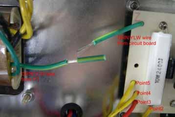
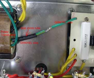
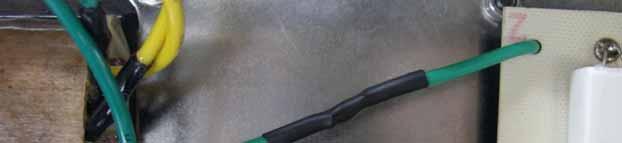
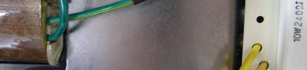
24 Connect the Green/Yellow wire from Power Transformer to the Green wire from the circuit board. See below:
 from the Power Transformer and")

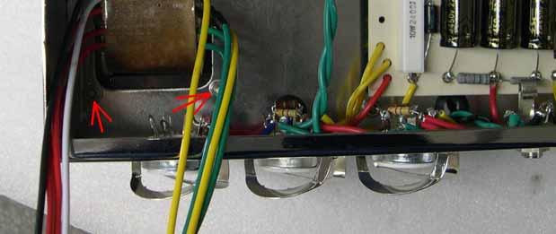
25 Twist the two yellow wires (5V 3A tap) from the Power Transformer and connect them to Pin 2 and Pin 8 on the rectifier tube socket. See red arrow below:
 with this amp.")
 and connect them directly to Pins 4 and 6 on the rectifier")

 goes to pin 6, and the positive lead")

26 Note: The following two steps are to be followed if you wish to use a 5AR4 rectifier (included) with this amp. If you wish to use a 5Y3 rectifier, twist the two red wires from the power transformer (PT) and connect them directly to Pins 4 and 6 on the rectifier tube socket. DO NOT use a 5AR4 without the diodes installed! Twist the two red wires from the PT together and run one of them to Pin 5 on the rectifier tube socket (5AR4). Solder a BYV26E diode from Pin 5 to Pin 6. The negative lead (with the black band) goes to pin 6, and the positive lead goes to Pin 5. Connect the other red wire from the PT to Pin 3 on the rectifier tube socket. Solder a BYV26E diode from Pin 3 to Pin 4. The negative lead (with the black band) goes to pin 4, and the positive lead goes to Pin 3.


27 Mount the SPST (2-pin) Standby switch, fuse holder, DPST (4-pin) Power switch and the pilot light to the front panel. From this point on, most of our connections will be made with push-on spade connectors. To install these connectors, do the following: 1. Strip approximately 1/8in or 3mm from the end of the wire 2. Slip the clear insulating cover over the wire 3. Using needle nose pliers, bend the two smaller tabs onto the wire, and bend the larger tabs onto the insulation. Make sure the wire is held in place firmly 4. Solder the wire where it meets the metal on the connector


28 Connect the black primary wire from the Power transformer to F2 on the fuse holder. Connect the white primary wire (230V) to P2 on the power switch. See the two pictures below:


29 Connect the Red/Yellow wire from Power transformer to S2 on the Standby switch. See below:


30 Make a short black wire and connect F1 on the fuse holder to P1 on the power switch.


31 Connect the two green wires from the power transformer to the two terminals on the pilot light. Connect the two green filament wires from the second 6V6 to the pilot light as well.


32 Power cord wiring Cut the IEC connector off the end of the end of the power cord. Strip off outer insulation and install connectors as shown:


33 Run the power cord through the rear of the chassis and fasten in place with the plastic strain relief clip. Make sure there is enough wire inside to reach the power switch. You may need to use a pair of pliers to squeeze the clip together to get it through the hole. Connect the brown wire to P3 and the blue wire to P4 on the power switch.


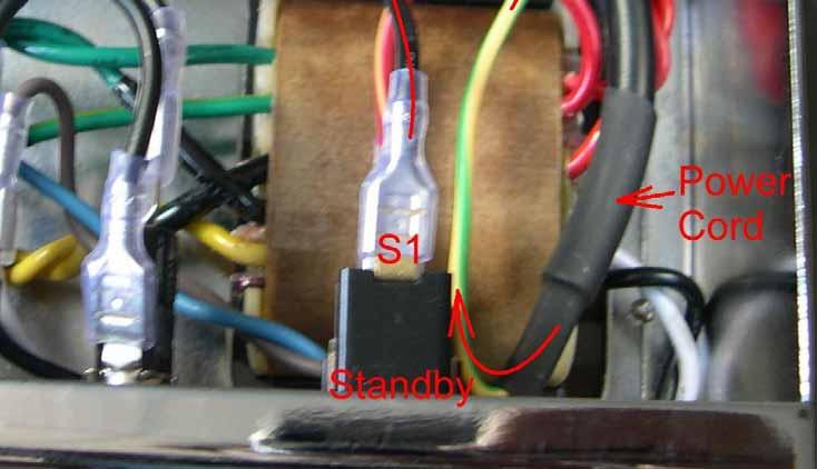
34 Make a short black wire and connect S1 on the Standby switch to the chassis ground. Connect the Yellow/Green wire from the Power Cord to the same chassis ground point.

35


36 Congratulations! You have just finished wiring the chassis. Compare your work to the pictures below and double-check all of your wiring. Pat yourself on the back, have a cup of tea (or the beverage of your choice), and take a break. We ll have your new amp up and jamming in no time.
37 Initial testing: Install the knobs and fuse, but don t install the tubes at this time. Put the standby switch in standby mode, the power switch off, and both volume knobs all the way down. Now, with the amp sitting on your workbench wiring side up, plug in the power cord and turn the power switch on. The pilot light should turn on at this point. If it doesn t, turn the amp off, unplug it, and check your wiring again. Check to see if the fuse is blown. If it is, there is a short somewhere in your wiring, or the AC line to the power switch is miswired. Don t proceed to the next step until the problem is fixed. Set your multimeter to the 20V AC range (or any AC range that will read voltages below 10V) and test the filament wires to each tube socket. Check to see that there is 6.3VAC between pins 2 and 7 on each 6V6/6P6 socket, and between pins 4/5 and 9 on each preamp socket. Check to see that there is 5VAC between pins 2 and 8 of the 5AR4 power tube socket. Note: Without the tubes installed, these voltages will run high. It is not unusual to see 6.8VAC on the 6.3v lines and 5.6VAC on the 5V line. If these voltages are half or double what they should be, you may have the wrong power transformer for your AC line current. Contact the seller for the correct transformer. Do not proceed until you have the correct voltages. From now on, we will be working with high voltages. Observe the following cautions: Connect the negative (black) lead of your multimeter to the grounded chassis, and measure all voltages in reference to ground with the red lead. Follow the one hand rule when testing. Only one hand should be in the chassis at a time. Keep your other hand in your pocket. Wear a heavy long sleeve shirt or jacket without any metal buttons on the sleeves. When you power off the amp to do work, unplug the amp from the wall and discharge the big capacitors (22uf 450v) first. Use a pair of pliers to hold a 10K (or thereabouts) resistor between the positive side of the middle capacitor (where the red wire connects) and the chassis ground for about 5 seconds. Use your multimeter to see that the voltages on the positive ends of each capacitor have dropped to a safe level. With the negative (black) lead of your multimeter attached to the chassis ground, flip the standby switch to turn on the high voltage supply. Set your multimeter to the 500V AC range or higher, and check the voltage at Pin 3 of the rectifier tube socket, and then at Pin 5. Both voltages should be around 355VAC. If you are using a 5Y3 rectifier without the diodes, do this test at pins 4 and 6 instead. There is no need to discharge the capacitors at this point without the rectifier tube in place. Turn the power off and install the rectifier tube. Make sure the key on the middle of the base of the tube matches up with the notch in the socket. You may need a helper to push down the wings of the tube retainer while you carefully press the tube firmly into place. With the standby switch in standby mode, turn the main power switch on. The rectifier tube should glow. Give it a couple of minutes to warm up and flip the standby switch to turn on the high voltage. First, let s measure the positive side of each big capacitor. Set your meter to the 500V DC range or higher. You should get high voltage (400+ volts) at the positive end of each capacitor. Each voltage will be different.
38 Now, measure the voltage at each pin of the 6V6/6P6 tube sockets. You should get high voltage (400+ VDC) at pins 1, 3, and 4 and 0VDC on pins 2, 5, 6, 7, and 8. Remember pins 2 and 7 carry 6.3VAC, but there should be no DC on those pins. On the preamp tubes, you should get high voltage on pins 1 and 5, and 0v on the rest of the pins. If you get high voltage on pins that should be 0V, check your soldering for solder bridges on the tube sockets. Final test: Discharge the capacitors and Install the rest of the tubes. Remember to line up the key on the output tubes to the notch in the tube socket. On the preamp tubes, there is a gap between pin 1 and pin 9 that needs to be lined up between the tube and the socket. Leave the tube shields off for now. Connect an 8 ohm speaker to the jack closest to the output tubes. Start with the standby switch in standby mode. Turn on the main power and observe the tubes. They should begin to glow. After the tubes warm up for a few minutes, flip the standby switch. With no instrument plugged in, there should be almost no noise coming from the speaker. Turn the tone all the way up, and then turn each volume control up and down and observe the noise level. No amp is 100% quiet, but if you did things right, you should hear almost no noise or hum even with all three knobs turned all the way up. Install tube shields on the preamp tubes, turn the volumes all the way down, and plug your guitar into one of the input jacks. Turn the corresponding volume knob up and start playing. Test all four input jacks. Try each one out at different volumes, and make sure the tone knob does what it should do. Troubleshooting: If you get no sound at all, there are still a few things to try. Concentrate on the output tubes and the output transformer wiring. Make sure that the green and black wires are connected to the tip and ground tabs on the output jacks respectively (Page 17). Go back to the output tube wiring on page 18 and check that you did everything right. Chopstick Test: It is a fact that most American amp technicians eat Chinese food with a fork, but ask for chopsticks anyway. A plain wood chopstick is a very useful diagnostic tool. Sure, you can use any non conductive stick like a pen, pencil, or a wand from Hogwarts, but where s the fun in that? Put the amp chassis on your workbench wiring side up with a speaker connected. Turn it on and wait for the tubes warm up. Turn the tone control all the way up, and both volumes at about ½ up (if you get a loud hum already, you can turn the volume down so the noise doesn t drive you crazy). Hold the chopstick vertical and tap the end on each component and soldering joint. You may hear a very soft click from the speaker, which is normal. When you hear a loud click, buzz, or hum, you ve just found a bad component or solder joint! This method works well for finding bad components on an older amp too. To standby or not to standby: In a cathode biased amp with a tube rectifier like the 5E3, it is not necessary to wait for the tubes to warm up before taking it off standby. In fact, you can just leave it off standby unless you need to take a break from playing, so the tubes are warm and ready to play immediately. However, if you are going to leave the amp for longer than ½ an hour, you should shut it off. Leaving tubes hot for hours without high voltage will reduce their lifespan.
39 5E3 Schematic
MOD 102 GUITAR AMP KIT (K-MOD102)
") MOD 0 GUITAR AMP KIT (K-MOD0) ON BASS TREBLE VOLUME MOD 0 TUBE AMP KIT 0 0 0 0 0 0 OFF Use these instructions to learn: How to build a tube amp. This tube guitar amplifier circuit is based on a classic
MOD 0 GUITAR AMP KIT (K-MOD0) ON BASS TREBLE VOLUME MOD 0 TUBE AMP KIT 0 0 0 0 0 0 OFF Use these instructions to learn: How to build a tube amp. This tube guitar amplifier circuit is based on a classic
MOD 102+ GUITAR AMP KIT (K-MOD102+)
") MOD 102+ GUITAR AMP KIT (K-MOD102+) ON BASS 4 6 TREBLE 4 6 VOLUME 4 6 7 7 7 STBY OFF STBY 2 8 MOD 102+ TUBE AMP KIT 1 9 modkitsdiy.com 0 10 Pull-MID BOOST 2 8 1 9 0 10 Pull-BRIGHT 2 8 1 9 0 10 Pull-TURBO
MOD 102+ GUITAR AMP KIT (K-MOD102+) ON BASS 4 6 TREBLE 4 6 VOLUME 4 6 7 7 7 STBY OFF STBY 2 8 MOD 102+ TUBE AMP KIT 1 9 modkitsdiy.com 0 10 Pull-MID BOOST 2 8 1 9 0 10 Pull-BRIGHT 2 8 1 9 0 10 Pull-TURBO
BLUE LIGHT FOR DYNACO STEREO 120, SCA-80, OR PAT-4 ROCKER SWITCHES
 BLUE LIGHT FOR DYNACO STEREO 120, SCA-80, OR PAT-4 ROCKER SWITCHES 2014 AkitikA, LLC All rights reserved Revision 1p5 April 8, 2014 Page 1 of 16 Table of Contents Table of Contents... 2 Table of Figures...
BLUE LIGHT FOR DYNACO STEREO 120 OR PAT-4 ROCKER SWITCHES
 BLUE LIGHT FOR DYNACO STEREO 120 OR PAT-4 ROCKER SWITCHES 2012 AkitikA, LLC All rights reserved Revision 1p3 April 18, 2012 Page 1 of 15 Table of Contents Table of Contents... 2 Table of Figures... 2 Section
SCA-80(Q) C11 REPLACEMENT ASSEMBLY MANUAL
 C11 REPLACEMENT ASSEMBLY MANUAL") SCA-80(Q) C11 REPLACEMENT ASSEMBLY MANUAL 2014-2016 AkitikA, LLC All rights reserved Revision 1p05 July 3, 2016 Page 1 of 15 Table of Contents Table of Contents... 2 Table of Figures... 2 Section 1: About
SCA-80(Q) C11 REPLACEMENT ASSEMBLY MANUAL 2014-2016 AkitikA, LLC All rights reserved Revision 1p05 July 3, 2016 Page 1 of 15 Table of Contents Table of Contents... 2 Table of Figures... 2 Section 1: About
Biasing the Vintage Series (Nomad, BelAir, VT50, Vintage 33)
") Biasing the Vintage Series (Nomad, BelAir, VT50, Vintage 33) This chapter will outline and guide you through the procedures of biasing the Vintage series amplifier. The procedures are broken down in a
Biasing the Vintage Series (Nomad, BelAir, VT50, Vintage 33) This chapter will outline and guide you through the procedures of biasing the Vintage series amplifier. The procedures are broken down in a
Hasse Mods for the Ampeg J20 Guitar Amp
 Hasse Mods for the Ampeg J20 Guitar Amp The following is adapted from a post I put up on The Gear Page, in the Amp Techincal forum. It shows the mods I did to my Ampeg J20. Okay, here s my mods for this
(2 DPDT 2 4 X
 Dynaco ST-120 with VTA driver board Kit instruction manual Triode/Pentode version Congratulations on your purchase of the Dynaco ST-120 with VTA driver board kit. Every effort has been made to give you
PAT-4 TOROIDAL TRANSFORMER ASSEMBLY MANUAL
 PAT-4 TOROIDAL TRANSFORMER ASSEMBLY MANUAL 2015 AkitikA, LLC All rights reserved Revision 1p3 August 22, 2015 Page 1 of 13 Table of Contents Table of Contents... 2 Table of Figures... 2 Section 1: About
White Light CLASSIC PEDAL KIT. Assembly Instructions WHEN YOU CAN T BUY IT BUILD IT. StewMac RARE / VINTAGE / HARD TO GET
 Sheet #i-2206 Updated 5/18 StewMac White Light CLASSIC PEDAL KIT Kit case is unpainted IN COLLABORATION WITH EarthQuakerDevices Assembly Instructions The White Light Overdrive is based on vintage overdrives
CLASSIC PEDAL KIT. Assembly Instructions WHEN YOU CAN T BUY IT BUILD IT. StewMac Monarch RARE / VINTAGE / HARD TO GET
 Sheet #i-2205 Updated 2/8 StewMac Monarch CLASSIC PEDAL KIT Kit case is unpainted IN COLLABORATION WITH EarthQuakerDevices Assembly Instructions The Monarch Overdrive is an all discrete, FET-based dirt
DCX2496 Linear Power Supply mod by
 DCX2496 Linear Power Supply mod by Construction Guide Linear Power Supply for the DCX2496 Introduction. One of my more rewarding modifications to the DCX2496 was the replacement of the stock I/O board
Handyman Motor Capacitor Meter PART NO
 Handyman Motor Capacitor Meter PART NO. 2225174 To test a motor-run capacitor in the field with no capacitance meter at hand, you had to hook up the capacitor through an extension cable to a 120V wall
DYNACO STEREO 120 C7 REPLACEMENT MANUAL
 DYNACO STEREO 120 C7 REPLACEMENT MANUAL 2013 AkitikA, LLC All rights reserved Revision 1p03 April 29, 2013 Page 1 of 15 Table of Contents Section 1: About This Manual... 3 Who Should Attempt this Project?...
64 REVERB UNIT KIT ORIGINAL 6G15 CIRCUIT
 REVERB UNIT KIT ORIGINAL G CIRCUIT Reverb you can't get from a pedal. ASSEBLY INSTRUCTIONS With loads of helpful tips! Contents About this iconic reverb unit.... How to build this kit!... Parts list....
DIY Synth Kit - Manual STUTTER SYNTH
 DIY Synth Kit - Manual STUTTER SYNTH Welcome to the DIY Synth - Manual This is a step-by-step guide to making your own electronic Synth. All you will need is your hands and your DIY Synth kit which includes
Kit1 300B Edition. Single Ended Triode 8 Watt. Construction Manual & User Guide Volume One
 Kit1 300B 2014 Edition Single Ended Triode 8 Watt Construction Manual & User Guide Volume One Contents Section 1: Receiving your kit...2 Section 2: The Mechanical section Preparation... 3 Tang Strips...
k" or #8 nut driver A pair of regular pliers can substitute for the nut drivers but will
 Page of 3 ARIES SYSTEM 300 MUSIC SYNTHESIZER Module AR-38 STEREO REVERB & OUTPUT ASSEMBLY INSTRUCTIONS The previous pages were written as a general guide to familiarize the builder with the components.
Build Your Own Clone Classic Brit 50 Kit Instructions (Revision 1.0)
") Build Your Own Clone Classic Brit 50 Kit Instructions (Revision 1.0) WARNING!!! HIGH VOLTAGE!!!! Tube amplifiers contain high voltage that can cause injury and even death. Please use extreme caution and
Build Your Own Clone Classic Brit 50 Kit Instructions (Revision 1.0) WARNING!!! HIGH VOLTAGE!!!! Tube amplifiers contain high voltage that can cause injury and even death. Please use extreme caution and
General Purpose Flasher Circuit
 General Purpose Flasher Circuit By David King Background Flashing lights can be found in many locations in our neighbourhoods, from the flashing red light over a stop sign, a yellow warning light located
MARK I. Maintenance and repair information.
 MARK I Maintenance and repair information. 1 Malfunctions can be cured easily when a proper diagnosis of the fault is made. Usually only one part (most often a tube) is all that has gone bad, and the Boogie
Instructions on installing the R/R to the front battery cover.
 April, 2008 Instructions on installing the R/R to the front battery cover. Please read all of the steps so you will be familiar with the complete relocation installation first. The purpose of this relocation
Prusa i3 Printer Assembly Guide
 Prusa i3 Printer Assembly Guide Special thanks to Carlos Sanchez and Miguel Sanchez for the graphics. All graphics captured from their great animation: http://www.carlos-sanchez.com/ Prusa3/ For copyright
DIY Synth Kit - Manual
 DIY Synth Kit - Manual Welcome to the DIY Synth - Manual This is a step-by-step guide to making your own electronic Synth. All the equipment you ll need to make your synth is your DIY Synth kit and of
These instructions show how to build the Remote Controlled Fart machine Sound Kit.
 Remote Controlled Fart Machine Assembly Instructions These instructions show how to build the Remote Controlled Fart machine Sound Kit. Tools Required Drill with 7/64, 3/16, and ¼ drill bits. Holt melt
How to bias: MTS3200, MTS3212 Rev A 8/1/2008 carvinservice.com
 How to bias: MTS3200, MTS3212 Rev A 8/1/2008 carvinservice.com - 1 - Only a certified technician should bias Carvin amps, this is very dangerous, you can get hurt, please be very careful when working with
How to bias: V3M, V3MC Rev A 9/23/2011
 How to bias: V3M, V3MC Rev A 9/23/2011 www.carvinservice.com - 1 - Only a certified technician should bias Carvin amps, this can be very dangerous, you can get hurt, please be very careful when working
Arlo Power Distribution Board Kit Rev B (#28996)
") Web Site: www.parallax.com Forums: forums.parallax.com Sales: sales@parallax.com Technical: support@parallax.com Office: (916) 624-8333 Fax: (916) 624-8003 Sales: (888) 512-1024 Tech Support: (888) 997-8267
Web Site: www.parallax.com Forums: forums.parallax.com Sales: sales@parallax.com Technical: support@parallax.com Office: (916) 624-8333 Fax: (916) 624-8003 Sales: (888) 512-1024 Tech Support: (888) 997-8267
THE PERSUADER DELUXE (K-980)
") THE PERSUADER DELUXE (K-0) BOOST VOLUME GAIN Unplug when not in use to save battery life. TO AMP IN The Persuader Deluxe Tube Drive modkitsdiy.com FROM GUITAR OUT LED VDC CENTER (-) ADAPTER Use these instructions
THE PERSUADER DELUXE (K-0) BOOST VOLUME GAIN Unplug when not in use to save battery life. TO AMP IN The Persuader Deluxe Tube Drive modkitsdiy.com FROM GUITAR OUT LED VDC CENTER (-) ADAPTER Use these instructions
Arlo Power Distribution Board Kit Rev B (#28996)
") Web Site: www.parallax.com Forums: forums.parallax.com Sales: sales@parallax.com Technical: support@parallax.com Office: (916) 624-8333 Fax: (916) 624-8003 Sales: (888) 512-1024 Tech Support: (888) 997-8267
Web Site: www.parallax.com Forums: forums.parallax.com Sales: sales@parallax.com Technical: support@parallax.com Office: (916) 624-8333 Fax: (916) 624-8003 Sales: (888) 512-1024 Tech Support: (888) 997-8267
MOD 101 GUITAR AMP KIT (K-MOD101)
") MOD 0 GUITAR AMP KIT (K-MOD0) ON MOD 0 TUE AMP KIT 5 6 7 5 6 7 5 6 7 8 8 8 9 9 9 OFF 0 0 0 0 0 0 POWER STANDY ASS TRELE VOLUME INPUT 5/ 6" Use these instructions to learn: How to build a tube amp. How
MOD 0 GUITAR AMP KIT (K-MOD0) ON MOD 0 TUE AMP KIT 5 6 7 5 6 7 5 6 7 8 8 8 9 9 9 OFF 0 0 0 0 0 0 POWER STANDY ASS TRELE VOLUME INPUT 5/ 6" Use these instructions to learn: How to build a tube amp. How
Installation of Raxiom Switchback Turn Signal Conversion Kit w/resistors
 Installation of Raxiom Switchback Turn Signal Conversion Kit w/resistors Overview: Below are the steps involved in the installation of the Raxiom Switchback Turn Signal LED lights in the 1987 1993 Ford
57 MINI TWEED 5W COMBO AMP KIT. One-knob titan of tone. ORIGINAL 5F1 CIRCUIT ASSEMBLY INSTRUCTIONS. With loads of helpful tips!
 7 MINI TWEED W COMBO AMP KIT ORIGINAL F CIRCUIT One-knob titan of tone. ASSEMBLY INSTRUCTIONS With loads of helpful tips! Contents About this iconic amp... How to build this kit!... Parts list.... 3 Tools
Remove the 3-11mm nuts holding mirror on. Don t drop the nuts!
 2005-2012 Ford Mustang Puddle Lamp Kit Parts List: Quantity: Tool List: LED Lamps 2 Flat head screwdriver Seals 2 Ratchet & Socket set OR Nuts 2 Adjustable Wrench Wiring harness 1 Drill & 11/16 th bit
Operation and Installation Manual
 Operation and Installation Manual G-Scale Graphics 5860 Crooked Stick Dr. Windsor, CO 80550 970-581-3567 GScaleGraphics@comcast.net www.gscalegraphics.net Revision A: Updated 2/7/2018 Page Overview The
Lab 4: Robot Assembly
 E11: Autonomous Vehicles Lab 4: Robot Assembly In this lab, you ll put together your very own robot! You should have a Mudduino and a chassis, as well as your kit of parts. Now it s time to put them all
Assembly and User Guide
 Assembly and User Guide 2 Amp Adjustable Electronic Load 30V and 20 Watts Max Powered by: 9V Battery Pico Load is a convenient constant current load for testing batteries and power supplies. The digital
Notice Regarding this Upgrade. WARNING! Danger Potential
 Notice Regarding this Upgrade WARNING! Danger Potential Although this kit has been designed to be easy-to-install, and has been tested in many installations; caution must be exercised when installing this
65 P-REVERB 15W COMBO AMP KIT. Sparkling bright, perfect for the surf. ORIGINAL AA1164 CIRCUIT ASSEMBLY INSTRUCTIONS. With loads of helpful tips!
 P- W COMBO AMP KIT ORIGINAL AA CIRCUIT Sparkling bright, perfect for the surf. ASSEMBLY INSTRUCTIONS With loads of helpful tips! Contents About this iconic amp... How to build this kit!... Parts list....
Arlo Power Distribution Board Kit (#28996)
") Web Site: www.parallax.com Forums: forums.parallax.com Sales: sales@parallax.com Technical: support@parallax.com Office: (916) 624-8333 Fax: (916) 624-8003 Sales: (888) 512-1024 Tech Support: (888) 997-8267
Web Site: www.parallax.com Forums: forums.parallax.com Sales: sales@parallax.com Technical: support@parallax.com Office: (916) 624-8333 Fax: (916) 624-8003 Sales: (888) 512-1024 Tech Support: (888) 997-8267
Depress each tab as you pull the bezel off. The bezels are tight. L.H. shown.
 2013-2014 Ford Mustang V6 & Boss 302 Lower Valance Fog Light Kit Parts List: Quantity: Tool List: Fog light & bulb with bracket 2 Flat head & Phillips screwdriver Black bezels 2 Ratchet & Socket set OR
WIRING THE HEATER POWER SUPPLY
 WIRING THE HEATER POWER SUPPLY Fig. 14 13/14 Take the longer PS board (with the 47R resistors and the fuse) and, using M3x6 screws, fix it to the chassis to the left of the mains transformer. The diodes
EE-101 ASSEMBLY MANUAL
 EE-101 ASSEMBLY MANUAL 2018 AkitikA LLC All rights reserved Revision 1p07 July 22, 2018 Page 1 of 28 Table of Contents Table of Contents... 2 Table of Figures... 3 Section 1: About This Manual... 4 Who
JHS 808. CLASSIC PEDAL KIT Assembly Instructions. StewMac
 heet #i-2150 Updated 12/17 tewmac JH 808 CLAIC PEDAL KI Assembly Instructions he JH808 is one of the great stompboxes from JH, makers of high-end effects pedals. Whenever JH adds a new pedal to their line,
Lakela nd H2 Low Speed Stator Coil Installation
 Lakela nd H2 Low Speed Stator Coil Installation Step 1: Place the stator assembly on a padded surface to protect the plastic signal generators, and orient it as shown in figure 1. The low speed coil is
QUASAR ELECTRONICS KIT No ELECTRONIC CAR IGNITION
 QUASAR ELECTRONICS KIT No. 1058 ELECTRONIC CAR IGNITION General Description The advantages of having an electronic ignition in your car are well known. Let us mention them again: 1. Perfect burning of
Chapter 2. Battery Charger and Base Assembly
 Chapter 2 Battery Charger and Base Assembly 11 CHAPTER 2. BATTERY CHARGER AND BASE ASSEMBLY 2.1 Section Overview This Lab teaches students how to assemble a Tekbot, in the following steps: Describe the
FITTING THE RELAY SWITCH BOARD FITTING THE INPUT SELECTOR SWITCH
 FITTING THE RELAY SWITCH BOARD Fit M3 x 12mm spacers to the COMPONENT side of the board. Use fibre washers under M3 screws on the SOLDER side of the board to avoid grounding the tracks. Push the completed
Note: Please read through the entire guide before attempting any kind of installation.
 KIT-RSP Installation Guide Version 1.3 Auber Instruments, 730 Culworth Manor, Alpharetta, GA 30022 e-mail: info@auberins.com Tel: 770-569-8420 www.auberins.com This is a PID controller kit installation
Assembly Instructions MP-P2 Power Supply and Chassis Base Plate
 Assembly Instructions MP-P2 Power Supply and Chassis Base Plate The MP-P2 Power Supply is the supply designed to power the mother board and its complement of plug-on boards including the MP-09 Microprocessor
Audio Regenesis. Power Supply Capacitor Replacement Board. Dynaco PAS 2, 3, 3X Preamplifiers. Installation Guide. For. Pacific Audio Regenesis
 Audio Regenesis Power Supply Capacitor Replacement Board For Dynaco PAS 2, 3, 3X Preamplifiers Installation Guide Pacific Audio Regenesis www.audioregenesis.com Thank you for choosing our power supply
Tweed 5E3 PCB Valve Junior Conversion Build Manual Tweed 5E3 PCB Valve Junior Conversion Build Manual v Feb of 40
 Tweed 5E3 PCB Valve Junior Conversion Build Manual 1 of 40 1. Introduction This manual contains instructions to convert an Epiphone Valve Junior, Harley Benton GA-5 or Legacy Valve Edition into a 14-18
Foreword and disclaimer:
 Installation guide for the ADA Depot MDRT transformer. Foreword and disclaimer: Thank you for purchasing this Machinator transformer kit. These kit suites the MP-1,/ MB-1. This kit also solves the famous
Installation MKIV Headlight Housings with Fog Lamps (Procedures apply to both MKIV Jetta and Golf)
") Page 1 This tutorial is provided as a courtesy by ECS Tuning. Service Procedure Installation Proper service and repair procedures are vital to the safe, reliable operation of all motor vehicles as well
Page 1 This tutorial is provided as a courtesy by ECS Tuning. Service Procedure Installation Proper service and repair procedures are vital to the safe, reliable operation of all motor vehicles as well
Solstice Electric Fryers SE Series Service Manual
 Solstice Electric Fryers SE Series Service Manual L22-330 R1 (10/12) Notice In the event of problems or questions about your order, contact the Pitco Frialator factory at (603) 225-6684. In the event of
Troubleshooting Guide for Okin Systems
 Troubleshooting Guide for Okin Systems More lift chair manufacturers use the Okin electronics system than any other system today, mainly because they re quiet running and usually very dependable. There
Build Instructions and User Guide
 Build Instructions and User Guide Getting Started To build the Rock Drill 4069 you will need: Solder Wire Cutters Soldering Iron Small pliers The kit is suitable for beginners or more experienced builders
66 BRIT-74X 18W COMBO AMP KIT. Leave your halfstack ORIGINAL BRITISH CIRCUIT ASSEMBLY INSTRUCTIONS. With loads of helpful tips!
 BRIT-74X 8W COMBO AMP KIT ORIGINAL BRITISH CIRCUIT Leave your halfstack at home! ASSEMBLY INSTRUCTIONS With loads of helpful tips! Contents About this iconic amp... How to build this kit!... Parts list....
The ability to make basic voltage and resistance measurements using a digital multimeter
 Seventh Circle Audio C84 Microphone Preamp Based on the innovative Double Balanced Microphone Amplifier circuit published by Graham John Cohen in 1984, the C84 microphone preamp offers exceptional performance
WARNING This manual should only be used by a qualified Service Technician. FinishPro 390/395 Airless/Air-Assisted Sprayer Repair Electrical Manual
 FinishPro 390/395 Airless/AirAssisted Sprayer Repair Electrical Manual First choice when quality counts. Rev. B 10/11 /07 FinishPro 395 3.00 ti9026a Red Yel Yel Air Hose Connection FinishPro 390 Exhaust
Wiring the 2015 FRC Control System
 Wiring the 2015 FRC Control System This document details the wiring of a basic electronics board for bench-top testing. The images shown in this section reflect the setup for a Robot Control System using
X-Type w/ non-premium sound amplifier installation instructions
 X-Type w/ non-premium sound amplifier installation instructions 1. Pull radio from dash (see Radio Removal Instructions ) 2. Disconnect wiring harness from back of radio by pushing in tab on plug and pulling
FiveFish Studios PSU-2448Plus+ Assembly Guide
 FiveFish Studios PSU-2448Plus+ Assembly Guide Copyright 2015-2017 FiveFish Audio Revision 1.02-20171105 No part of this document may be reproduced, either mechanically or electronically, posted online
DECIDUOUS FILTER ASSEMBLY INSTRUCTIONS RECOMMENDED TOOL AND SUPPLY LIST DECIDUOUS FILTER KIT PARTS LIST
 DECIDUOUS FILTER ASSEMBLY INSTRUCTIONS Thank you for purchasing the Deciduous Filter Effect Pedal Kit from Mammoth Electronics! This is an intermediate level kit and we have made every effort to make the
CAPI BB2521 Build Guide & BOM
 This is a very simple build. I only have a few tips and things to look out for. I do recommend following these steps due to the diode/transistor relationship. 1. Install the three ceramic caps. If you
Trouble Shooting Guide for Hubbell Systems
 Trouble Shooting Guide for Hubbell Systems NOTE: Hubbell Special Products discontinued operations in 2008, so there is a very limited number of repair parts available for motor repair. In some ways, this
How to bias: Vintage 16 Rev C 6/27/2012 carvinservice.com
 How to bias: Vintage 16 Rev C 6/27/2012 carvinservice.com - 1 - Only a certified technician should bias Carvin amps, this is very dangerous, you can get hurt, please be very careful when working with any
HOW - TO WIRING & LIGHTING
 HOW - TO WIRING & LIGHTING Tool And Material Checklist Test Light Service Manual Penetrating Oil Long-Nose Pliers T-Square or Right Angle Screwdriver Black Electrical Tape Fuses Fuse Puller Cloth or Paper
Rostra Electronic Cruise Control Install On a Stratoliner or Roadliner
 Rostra Electronic Cruise Control Install On a Stratoliner or Roadliner MATERIALS LIST: 1 - Rostra Part # 250-1223 (www.brandondist.com/products/cruise1223.htm) 1 - Signal Splitter part # 250-4369 1 - Engagement
THIS GUIDE IS INTENDED FOR DEALERS AND SOLAR COMFORT TECHNICIANS ONLY AND IS NOT MEANT OR INTENDED TO BE REPRODUCED OR DISTRIBUTED TO THE CONSUMER
 THIS GUIDE IS INTENDED FOR DEALERS AND SOLAR COMFORT TECHNICIANS ONLY AND IS NOT MEANT OR INTENDED TO BE REPRODUCED OR DISTRIBUTED TO THE CONSUMER Table of Contents Page Tools Needed (A) 3 Replacement
PM-200 POWER SUPPLY MODULE v3.2 ASSEMBLY & INSTALLATION INSTRUCTIONS
 PM-200 POWER SUPPLY MODULE v3.2 ASSEMBLY & INSTALLATION INSTRUCTIONS WARNING: Voltages inside the amplifier CAN & WILL KILL YOU! You MUST know how to work around HIGH VOLTAGE safely. If you do not, get
POWER SUPPLY MODEL XP-800. TWO AC VARIABLE VOLTAGES; 0-120V and 7A, PLUS UP TO 10A. Instruction Manual. Elenco Electronics, Inc.
 POWER SUPPLY MODEL XP-800 TWO AC VARIABLE VOLTAGES; 0-120V and 0-40V @ 7A, PLUS 0-28VDC @ UP TO 10A Instruction Manual Elenco Electronics, Inc. Copyright 1991 Elenco Electronics, Inc. Revised 2002 REV-I
G203V / G213V MANUAL STEP MOTOR DRIVE
 G203V / G213V MANUAL STEP MOTOR DRIVE PRODUCT DIMENSIONS PHYSICAL AND ELECTRICAL RATINGS Minimum Maximum Units Supply Voltage 18 80 VDC Motor Current 0 7 A Power Dissipation 1 13 W Short Circuit Trip 10
VECTRIX VX-2 SERVICE MANUAL. Version 1.0/May 2011 VECTRIX, LLC
 www.vectrix.com CONTENTS SECTION A: Tools 1 Tools Needed SECTION B: Mechanical Parts 1 Front Fairing 2 Front Console Cover 3 Speedometer Cover 4 Front Vertical Panel Cover-Lower 5 Front Vertical Panel
Wiring the FRC Control System
 Wiring the FRC Control System This document details the wiring of a basic electronics board for bench-top testing. Some images shown in this section reflect the setup for a Robot Control System using Spark
TIP SHEET T0937. Installation Tips For RS00/PS00 + ADS-TBSL-PL + SPDT
 Installation Tips For RS00/PS00 + ADS-TBSL-PL + SPDT TIP SHEET T0937 Thank you for purchasing your remote start from MyPushcart.com - an industry leader in providing remote starts to do-it-yourself installers
Installation Tips for your Crimestopper/ProStart Remote Start system (add-on for GM vehicles) v1.02 updated 1/16/2013
 v1.02 updated 1/16/2013") Installation Tips for your Crimestopper/ProStart Remote Start system (add-on for GM vehicles) v1.02 updated 1/16/2013 Thank you for purchasing your remote start from MyPushcart.com - an industry leader
Installation Tips for your Crimestopper/ProStart Remote Start system (add-on for GM vehicles) v1.02 updated 1/16/2013 Thank you for purchasing your remote start from MyPushcart.com - an industry leader
TONY S TECH REPORT. Basic Training
 TONY S TECH REPORT (Great Articles! Collect Them All! Trade them with your friends!) Basic Training OK YOU MAGGOTS!! Line up, shut up, and listen good. I don t want any of you gettin killed because you
Installing LED lights in a Hypercharger By Keith Edwards Joker s Wild! (Wildjokr)
") Installing LED lights in a Hypercharger By Keith Edwards Joker s Wild! (Wildjokr) THINGS YOU WILL NEED: A Hypercharger (duh!) LEDs (The ones I got were from Benny Bryant at Fantasies on Wheels in Sylacauga,
Installing LED lights in a Hypercharger By Keith Edwards Joker s Wild! (Wildjokr) THINGS YOU WILL NEED: A Hypercharger (duh!) LEDs (The ones I got were from Benny Bryant at Fantasies on Wheels in Sylacauga,
Connecting the rear fog light on the A4 Jetta, while keeping the 5 Light Mod
 Connecting the rear fog light on the A4 Jetta, while keeping the 5 Light Mod DISCLAIMER: I'm human and make mistakes. If you spot one in this how to, tell me and I'll fix it This was done on my 99.5 Jetta.
MOTHMAN FUZZ ASSEMBLY INSTRUCTIONS RECOMMENDED TOOL AND SUPPLY LIST MOTHMAN FUZZ KIT PARTS LIST
 MOTHMAN FUZZ ASSEMBLY INSTRUCTIONS Thank you for purchasing the J201 Clean Boost Pedal Kit from Mammoth Electronics! This is a intermediate level kit that and we have made every effort to make the assembly
D6, D7, D8, D9, D12, D13, D14, D15, D16, D17, D18, D19. Schottky rectifier diode. 1N5817-1N5819 or SB130
 Roll Your Own ljunggrenaudio.com Altered States version 1.0 Bills Of Material Qty Value 12 1N4148 2 1N5818 4 1N750 4.7V 4 220p Device Diode Diode Zener diode Capacitor 30 100n 4 15p 8 560p 1 5x2 pin Capacitor
Zkit60 Introduction. Finished Zkit60 with cover off, one volume control, built in an Ebay DIY chassis
 Zkit60 Introduction The Zkit60 design was originally done in 1981 by an employee of Audio by VanAlstine, Woodbury MN. Nothing became of it, and the one page, hand drawn schematic sat in a file cabinet
Shelby GT500 Front Fascia Conversion Kit (05-09 All) Item # Installation Time: 1 Day. Required tools:
 Item # Installation Time: 1 Day. Required tools:") Shelby GT500 Front Fascia Conversion Kit (05-09 All) Item #53611 Installation Time: 1 Day Required tools: Phillips Screw driver 10mm Socket + Ratchet/Wrench 8mm Socket + Ratchet/Wrench 5mm Socket + Ratchet/Wrench
Shelby GT500 Front Fascia Conversion Kit (05-09 All) Item #53611 Installation Time: 1 Day Required tools: Phillips Screw driver 10mm Socket + Ratchet/Wrench 8mm Socket + Ratchet/Wrench 5mm Socket + Ratchet/Wrench
QUASAR ELECTRONICS KIT No WINDSCREEN WIPER CONTROLLER
 QUASAR ELECTRONICS KIT No. 1093 WINDSCREEN WIPER CONTROLLER General Description This is a very useful accessory for any car. It can adjust the frequency of operation of the windscreen wipers between once
The ability to make basic voltage and resistance measurements using a digital multimeter
 Seventh Circle Audio N72 Microphone Preamp Based on the BA183 amplifier circuit used in the 1066, 1073, 1272, and other Neve console modules, the N72 microphone preamp will deliver the same immediately
Contacts The moveable contact, which is the one affected by the armature is sometimes referred to as the hinge contact.
 Relays & Wiring 101 Basically, a relay is an electrically operated, remotely controlled switch. A simple electromagnetic relay is an adaptation of an electromagnet. It consists of a coil of wire surrounding
Wiring the 2016 FRC Control System
 Wiring the 2016 FRC Control System This document details the wiring of a basic electronics board for bench-top testing. The images shown in this section reflect the setup for a Robot Control System using
LV2000. revision 1.5. Low Voltage Power Supply Retrofit Kit for Wells-Gardner Color XY Monitor, model 19K6100. Installation Instructions ! WARNING!
 LV2000 revision 1.5 Low Voltage Power Supply Retrofit Kit for Wells-Gardner Color XY Monitor, model 19K6100 Installation Instructions! WARNING! To successfully install this kit requires that you have good
ALL AMERICAN. CLASSIC PEDAL KIT Assembly Instructions. StewMac
 heet #i-2153 Updated 12/17 tewmac ALL AMERICAN CLAIC PEDAL KI Assembly Instructions he ALL-AMERICAN is one of the great stompboxes from JH, makers of high-end effects pedals. Whenever JH adds a new pedal
Troubleshooting Guide for Limoss Systems
 Troubleshooting Guide for Limoss Systems NOTE: Limoss is a manufacturer and importer of linear actuators (motors) hand controls, power supplies, and cables for motion furniture. They are quickly becoming
This LED flashtube kit covers models 400, 404, 500, 504, 600, 680 & 506.
 L.E.D. INSTRUCTIONS I D T S O T U B I R M O C R Y N A P Kit contains: This LED flashtube kit covers models 400, 404, 500, 504, 600, 680 & 506. For the power supply: 1-LED power supply circuit board, 2
Safe-T-element Installation Instructions
 Safe-T-element Installation Instructions For: PTI STEZA (2x2 Burner Configuration) & PTI STEZB (3x1 Burner Configuration) Revision K (May. 3 2012) TABLE OF CONTENTS 1. PREPARATION... 3 1.1 General Safety
Step #1 From your spool of 18 gauge primary wire, cut between 11 and 21 three inch strips of wire. You will only need 11 for the ROV, but it is good t
 How to make a ROV! Step #1 From your spool of 18 gauge primary wire, cut between 11 and 21 three inch strips of wire. You will only need 11 for the ROV, but it is good to have extras. Using the wire cutter,
Grant Fidelity RITA-880S Tube Amplifier
 www.grantfidelity.com Ph: 1-888-477-5379 Grant Fidelity RITA-880S Tube Amplifier Thank you for your purchase of the Grant Fidelity Reference Integrated Tube Amplifier (RITA-880). The product was originally
G213V STEP MOTOR DRIVE REV 7: March 25, 2011
 Thank you for purchasing the G213V drive. The G213V is part of Geckodrive s new generation of CPLD-based microstep drives. It has short-circuit protection for the motor outputs, over-voltage and under-voltage
Tip: LED Lighting for the 4367 SBB Euro City Set, 4366 and 4368 Cars Date: , Corrections Modified , Photos
 Hi All, I have had the 4367 SBB Euro City set with extra cars 4366 and 4368 since 1998, apart from a test run on the layout they have stayed in storage ever since. I decided to change some rolling stock
Ford Mustang V6 OEM-Style Fog Light Kit Parts List: Quantity: Tool List:
 2015-2017 Ford Mustang V6 OEM-Style Fog Light Kit Parts List: Quantity: Tool List: LED Foglights/ Bezels 2 Flat head & Phillips screwdriver (if you ordered part#3600) Ratchet & Socket set OR Wiring harness
Amp & Speaker Upgrade Install Instructions for Batwing Fairing
 Amp & Speaker Upgrade Install Instructions for Batwing Fairing Tools Needed: 1/2 inch Socket Wire Cutters 7/16 inch Socket Wire Strippers 10 mm Socket Phillips Screwdriver 1/2 inch Ratchet Wrench T25 Torx
TIP SHEET. Installation Tips for your RS IB-MUX / PKUMUX (D) + SPDT T1205 v1.2 4/3/14. 1 P a g e
 + SPDT T1205 v1.2 4/3/14. 1 P a g e") Installation Tips for your RS-150 + IB-MUX / PKUMUX (D) + SPDT T1205 v1.2 4/3/14 TIP SHEET Thank you for purchasing your remote start from MyPushcart.com - an industry leader in providing remote starts
Installation Tips for your RS-150 + IB-MUX / PKUMUX (D) + SPDT T1205 v1.2 4/3/14 TIP SHEET Thank you for purchasing your remote start from MyPushcart.com - an industry leader in providing remote starts