JANUARY 2015 NOMENCLATURE. TOOLS REQUIRED 3/8" & 7/16" Can wrench or socket 1/4 Nut driver or screwdriver Snips Fiber optic cable opening tools
|
|
|
- Blanche Peters
- 6 years ago
- Views:
Transcription
 2. Organizer with 4-Port End Plate Assembly 3. Transport Tubing Kit (1) (In Dome Kits for Unitube/Ribbon Applications) 4. Dome Gasket (1) 5.")
1 JANUARY 2015 COYOTE Dome Closure 6-1/2" x 17" Be sure to read and completely understand this procedure before applying product. Be sure to select the proper PREFORMED TM product before application NOMENCLATURE 1. Dome cover (1) 2. Organizer with 4-Port End Plate Assembly 3. Transport Tubing Kit (1) (In Dome Kits for Unitube/Ribbon Applications) 4. Dome Gasket (1) 5. Dome Collar (1) 6. Silicone Lubricant (4 five gram packets) 7. Cable Grommet (2) 8. Hose Clamp (4) 9. Strength Member Bracket (2) 10. Disposable Glove (1) TOOLS REQUIRED 3/8" & 7/16" Can wrench or socket 1/4 Nut driver or screwdriver Snips Fiber optic cable opening tools Catalog Number " x 17" COYOTE Dome Closure Kits Description COYOTE 6.5" x 17" Dome Closure for Buffer Tube Applications. Includes: (2) Grommets, (1) Buffer Tube Organizer Assembly with 4-Port End Plate Assembly, (1) Dome, (1) Collar Assembly, (1) Gasket, (1) Small Parts Bag COYOTE 6.5" x 17" Dome Closure for Unitube/Ribbon Applications. Includes: (2) Grommets, (1) Transition Tray Organizer Assembly with 4-Port End Plate Assembly, (1) Dome, (1) Collar Assembly, (1) Gasket, (1) Transition Tubing Kit, (2) Transport Tubing Kits, (1) Small Parts Bag Accessory Kits COYEPFIX1 COYOTE Dome End Plate Fixture Mounting Brackets Aerial Mounting Bracket (Dome Mount) - Strand Applications Aerial Adjustable Offset Mounting Bracket (Dome Mount) - Strand Applications Aerial Mounting Bracket (Dome Mount) - ADSS Applications Aerial Adjustable Offset Mounting Bracket (Dome Mount) - ADSS Applications Pole/Wall Mounting Bracket Universal Mounting Bracket Kit for Hand Hole Applications Swing Arm for Hand Hole Applications Manhole Support 1
2 Splice Tray/Closure Capacities for 6.5" x 17" COYOTE Dome Closures Splice Tray Catalog # Low Profile LITE-GRIP (24 ct) Splice Type Trays per Closure Closure Splice Capacity Single Fusion LITE-GRIP (40 ct) Single Fusion LITE-GRIP (144 ct) LGSTR144 Mass Fusion/ Ribbon COYOTE Grommet Chart For use in COYOTE GLC, Aerial, LCC, Dome, In-Line RUNT, Taut & Terminal Closures PLP Catalog Number Cable Range Inches (mm) Description Splitting Location (11-15 mm) 1-entry grommet (15-22 mm) 1-entry grommet (22-25 mm) 1-entry grommet (25-32 mm) 1-entry grommet (11-15 mm) 2-entry grommet (8-11mm) 4-entry grommet ( mm) 4-entry grommet ( mm) ( mm) and flat drop 4-entry grommet (3-6 mm) 6-entry grommet (11-15 mm) (3-6 mm) 7-entry grommet (3-6 mm) 8-entry grommet NOTE: Grommet Kit contains (1) Grommet, (1) Cable Measure Tape, (2) Silicone Lubricant Packs, (1) Set of Plugs & (1) Glove Preformed Line Products Company. All rights reserved.


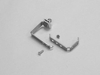
3 End Plate Preparation Step #4 Reassemble organizer assembly to end plate with mounting clip and 1/4" hex bolt and nut. Step #1 Remove support bar mounting clip from organizer assembly. Mounting Clip 1/4" Hex Bolt Hex Nut Cable Preparation Step #2 Remove end plate from organizer assembly. Step #5 Measure cable to determine diameter and hole location to use in grommet. Step #3 Remove the end plate caps from the selected ports and break out the tabs. Step #6a If using cut cable, insert cable through grommet. If your application requires express/balloon/ring cut cables, see Step 7 for grommet slitting procedure. Cable Diameter Range Install plug in unused port 3


 for mid sheath applications")


4 Step #6b Installing Figure 8 Style Cables and Cables with Tracer Wires - Remove tracer wire or ground wire from the portion of the cable that will be positioned in the grommet and insert cable into grommet. Step #8 Prepare loose tube/buffer tube or unitube/ ribbon cable(s) for cut applications. Cable with Tracer Wire NOT CORRECT Min. of 77" (2.0 m) Not Correct Installation NOT CORRECT Figure 8 Style Cable Correct Installation Minimum Sheath Opening for Cut Cable Applications Min. of 77" 2.0 m PLP Tip: Leave about 8" (203 mm) of strength member to trim later. Not Correct Installation Step #7 Correct Installation Grommet Slitting If slitting is required, lay grommet on a stable flat surface. Position utility knife with the cutting edge against the top surface and cut through grommet. Consult grommet chart on page 2 for slitting locations of all grommets. Step #9a Prepare loose tube/buffer tube or unitube/ ribbon cable(s) for mid sheath applications (Express/Balloon/Ring Cut). 77" (2.0 m) Buffer (Loose) Tube Cable OFFICE/C.O. Buffer Tube (After Cut) A X Ribbon Cable PLP Tip: Use a pen to sketch slitting lines on top surface of grommet prior to cutting. 77" (2.0 m) OFFICE/C.O. NOT CORRECT Slit Slit Not Correct Slitting Angle Slit Slit Correct Slitting Angle Ribbon (After Cut) NOTE: When expressing ribbons in the transition tray of the closure at this measurement, the maximum number of ribbons that can be expressed is 24 ribbons (288 fibers). For Applications Where Fiber is Dedicated to the Splice Point Sheath Opening Min. of 77" (2.0 m) Fiber/Buffer Tube Cut Location A (see image above) X A PLP Tip: Leave about 8" (203 mm) of strength member to trim later. 4
5 Step #9b B X Prepare loose tube/buffer tube or unitube/ ribbon cable(s) for mid sheath applications (Express/Balloon/Ring Cut). Buffer Tube (After Cut) 154" (3.9 m) Buffer (Loose) Tube Cable OFFICE/C.O. Cable Sheath Opening for Applications Where Fiber is Expressed through the Buffer Tube Step #9c Prepare loose tube/buffer tube cable(s) for expressed fiber (buffer tube window cut). C X 112" (2.8 m) Buffer Tube Opening Location for Window Cut OFFICE/C.O. Buffer Tube (After Cut) X C B X Ribbon (After Cut) 154" (3.9 m) Ribbon Cable OFFICE/C.O. Buffer Tube Opening Location for Window Cut For Applications Where Fiber is Expressed through the Buffer Tube Sheath Opening 112" (2.8 m) Buffer Tube Opening Location C (see image above) PLP Tip: Leave about 8" (203 mm) of strength member to trim later. Ribbon (After Cut) NOTE: When expressing ribbons in the transition tray of the closure at this measurement, the maximum number of ribbons that can be expressed is 12 ribbons (144 fibers). For Applications Where Fiber is NOT Dedicated to the Splice Point Sheath Opening Max. of 154" (3.9 m) Fiber/Buffer Tube Cut Location B (see image above) Step #10 Prepare Central/Buffer Tube(s) for Unitube/ Ribbon Cable Applications. Cable in Bottom Entry Ports 4.5" (11.3 cm) PLP Tip: Leave about 8" (203 mm) of strength member to trim later. Cable in Top Entry Ports 1.5" (3.8 cm) 5
 of the Kevlar.")


.")

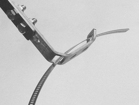
6 Step #11 If the cable contains Kevlar, braid roughly 3" (7.2 cm) of the Kevlar. Step #15 Position strength member under cap of strength member bracket. Strength Member 3" (7.2 cm) Step #12 Align sheath opening with end of slot of the strength member bracket as shown. Step #16 If the cable contains Kevlar, wrap the braided Kevlar around the stud of the cap as shown. Cable Sheath Opening Braided Kevlar Step #13 Trim strength member(s) flush with end of the strength member bracket(s). Strength Member Bracket Step #17 Tighten nut of cap to secure strength member and braid under the cap. Step #14 Install cap on strength member bracket. Cap 6 Kevlar is a registered trademark of DuPont.


.")


7 Step #18 Secure cable to strength member bracket with hose clamp. Step #21 Secure shielded cable to strength member bracket with hose clamp. NOTE: Visually inspect to confirm buffer tubes are not pinched or distorted as cable is secured to bracket with hose clamp. Attaching Shielded Cable to Strength Member Bracket Step #22 Lubricate the outer surface of the grommet. Step #19 For shielded cable applications, PLP recommends using a 3M 4460-D/FO Fiber Optic Shield Connector (PN: ). Install shield connector on cable and insert stud of shield connector through slot of strength member bracket. Lubricate sealing surface of grommet with silicone lubricant provided. NOTE: Visually inspect to confirm buffer tubes are not pinched or distorted as shield connector is secured to bracket. Follow standard company practices when applying shield connector to cable. Step #23 Position grommets in end plate slots. Do not align grommet slit with end plate seam. Step #20 Secure shield connector to strength member bracket with nut and secure cable strength member under cap of the strength member bracket. NOTE: Visually inspect to confirm buffer tubes are not pinched or distorted as shield connector is secured to bracket. 7


8 Step #24 Position slot of strength member bracket leg over stud and pull back cable. Step #26 Install cable caps and secure with hex bolts. Step #25 Install strength member bracket on stud. Install lock washer and nut against the bracket, but do not tighten fully, so the bracket can slide as the grommet is inserted. NOTE: Tighten bolts by hand evenly until cable cap is fully seated (DO NOT USE POWER TOOLS TO TIGHTEN BOLTS). When using a can wrench or nut driver, the installed torque is 35 to 40 in-lbs. NOTE: TIGHTEN ALL UNUSED CABLE CAPS. IMPORTANT: TIGHTEN DOWN THE STRENGTH MEMBER BRACKET AFTER THE CAPS ARE TIGHTENED. Step #27 Complete end plate assembly. Lock Washer & Nut 8


 to splice tray(s) and secure.")
9 Buffer Tube Applications Unitube Applications Step #28 Route and store buffer tubes in storage brackets. Step #30 Route and secure central tube of unitube cables to transition tray. Tie Wraps Step #31 Use transition tubes to route fibers or ribbons from upper cable ports. Transition Tube Step #29 Route buffer tube(s) to splice tray(s) and secure. Step #32 Route feeder fibers or ribbons within transition tray. 9


 into")


10 Step #33 Route express fibers or ribbons under clips. Splice Tray Management Organizer Clip Step #37 Route incoming fibers in splice tray. Splices Step #34 Insert fibers or ribbons to be routed to splice tray(s) into transport tube(s) and secure tubes to transition tray. Splices Step #35 Install cover on transition tray. Cover Step #38 Route outgoing fibers in splice tray. Splices Step #36 Route transport tube(s) to splice tray(s) and secure. Splices

 with hold down strap.")
 to assure that the cable caps are fully")


11 Step #39 Splice incoming fibers to outgoing pigtail fibers per your accepted company practices. Step #43 Work the gasket into the groove. Step #40 Secure splice tray(s) with hold down strap. Before After Step #44 Re-tighten all cable cap bolts (step #26) to assure that the cable caps are fully seated. When using a can wrench or nut driver, the installed torque is 35 to 40 in-lbs. Step #45 Position the dome over end plate. Dome & Collar Installation Step #41 Lubricate all surfaces around gasket with silicone lubricant to assure easy assembly and closure re-entry. Lubricate all inner surfaces of the gasket. Step #46 Position the collar flat on the work surface in front of the closure as shown below. Lubricate all outer surfaces of the gasket. Step #42 Slide end plate gasket onto end plate and press into groove. Make sure gasket is seated in groove of end plate 11


12 Step #47 While holding the collar in place, compress a portion of the end plate into the dome and insert them in the groove of the collar near the latch, as shown below. Step #49 Check to make sure the lip of the dome is captured within the collar half Front Side Lip of dome is captured within collar. Back Side Lip of dome is captured within collar. Step #48 While holding the collar in place, push against the end of the dome and slightly lift and push the other half of the dome up and over the lip of the collar with your fingers to fully install the dome in the collar half. Step #50 Install the other collar half onto the closure. Step #51 Secure the collar with the latch and pin. 12


13 Flash Test Procedure Step #54 Spray all sealing surfaces of the dome end-plate with soapy water to determine if there are any leaks. Step #52 Remove cap from air valve of end plate. Step #53 Pressurize closure up to a max of 10 psi. Step #55 Release the pressure in the closure using the bump on the top of the air valve cap. 13
 Leak occurring at the corner of the cable port due to the cap of the cable port")
 Leak occurring at the corner of the cable port To resolve, remove collar, remove")
 22.")


14 Common End Plate Leaks During Flash Testing 17.85" (453 mm) Leak occurring at the corner of the cable port due to the cap of the cable port not being fully tightened. 8.57" (218 mm) 10.04" (256 mm) Leak occurring at the corner of the cable port To resolve, remove collar, remove End Plate/ Organizer Assembly from the Dome, and tighten bolts on end cap where leak occurred. Reassemble and flash test to confirm that the leak has stopped. 8.57" (218 mm) 22.60" (574 mm) Leak occurring at the cable entry of the grommet due to the cable not being within the stated cable diameter range of the grommet Leak occurring at the cable entry of the grommet To resolve, remove collar and remove End Plate/Organizer Assembly from the Dome. Remove end cap where leak occurred, remove grommet, remeasure cable with measure tape provided and select proper grommet. Reassemble the components and flash test the closure to confirm that the leak has stopped. 14
 and 6.")


15 Step #56a Aerial Mounting Options For 6.5" Dome Strand Mount Aerial Offset Bracket Kit (P/N: ) and 6.5" Dome ADSS Mount Aerial Offset Bracket Kit (P/N: ). Assemble each bug nut or ADSS clamp to each top aerial offset bracket as shown below. Step #56c For 6.5" Dome Strand Mount Aerial Offset Bracket Kit (P/N: ) and 6.5" Dome ADSS Mount Aerial Offset Bracket Kit (P/N: ). For Taller Spacing. Align the top aerial offset bracket with the bottom aerial offset bracket in either Position 1 or Position 2 as shown below. Secure the top aerial offset bracket to the bottom aerial offset bracket with the bolts and keps nuts provided. Strand Clamp Position 1 Strand Clamp Shown ADSS Clamp Position 2 Strand Clamp Shown Step #57 6.5" Dome Strand Mount Aerial Offset Bracket Kit (P/N: ) and 6.5" Dome ADSS Mount Aerial Offset Bracket Kit (P/N: ). Insert hose clamp through slots in each of the bottom aerial offset brackets. Step #56b For 6.5" Dome Strand Mount Aerial Offset Bracket Kit (P/N: ) and 6.5" Dome ADSS Mount Aerial Offset Bracket Kit (P/N: ). For Shorter Spacing. Align the top aerial offset bracket with the bottom aerial offset bracket in either Position 1 or Position 2 as shown below. Secure the top aerial offset bracket to the bottom aerial offset bracket with the bolts and keps nuts provided. Step #58 Slots 6.5" Dome Strand Mount Aerial Offset Bracket Kit (P/N: ) and 6.5" Dome ADSS Mount Aerial Offset Bracket Kit (P/N: ). Tighten each hose clamp around the dome. Position 1 ADSS Clamp Shown Position 2 ADSS Clamp Shown 15
 and 6.")
.")

. Secure the Universal Mounting Bracket to the inner wall of the hand hole using 2 screws.")

16 Step #59 Strand Aerial Offset Bracket shown secured on a 6.5" Dome 6.5" Dome Strand Mount Aerial Offset Bracket Kit (P/N: ) and 6.5" Dome ADSS Mount Aerial Offset Bracket Kit (P/N: ). Bracket installed on dome closure. Step #62 COYOTE Universal Mounting Bracket for Hand Hole Applications (P/N: ). Position the brackets in the banding channels of the dome. Tighten the banding until the brackets are secure. Step #60 Hand Hole Mounting Option COYOTE Universal Mounting Bracket for Hand Hole Applications (P/N: ). Secure the Universal Mounting Bracket to the inner wall of the hand hole using 2 screws. Step #63 COYOTE Universal Mounting Bracket for Hand Hole Applications (P/N: ). Slide the hanger brackets into the proper slots of the Universal Mounting Bracket and snap the hinged lid into place to secure the hanger brackets. Step #61 COYOTE Universal Mounting Bracket for Hand Hole Applications (P/N: ). Insert banding (plastic or metal) through the slots of the hanger brackets. 16
. Step #64 The 6.")


17 Pole/Wall Mounting Option Step #65 The 6.5" COYOTE Dome Pole/Wall Mount Bracket (P/N: ). Step #64 The 6.5" COYOTE Dome Pole/Wall Mount Bracket (P/N: ). Position the bolts through the stud mount plate as shown, and install lock nuts on bolts until there is a 1/8" (3 mm) gap between the nut and the stud mount plate. Slide the bolts of stud mount plate into the slots of the pole/wall mount bracket as shown and tighten the lock nuts until the plates are secure. Stud Mount Plate Stud Mount Plate Pole/Wall Mount Bracket Secure Lock Nuts 1/8" (3mm) 17
.")


18 Step #65 The 6.5" COYOTE Dome Pole/Wall Mount Bracket (P/N: ). Step #66 The 6.5" COYOTE Dome Pole/Wall Mount Bracket (P/N: ). Attach the dome pole/wall mount bracket to a pole or wall with either 5/8" through bolts, 1/4" lag screws, or banding straps. 1/4" Lag Screw Hole Attach the COYOTE Dome closure to the pole/ wall mount bracket by inserting the studs of the dome closure end plate through the stud holes of the stud mount plate and securing with the lock nuts provided. Banding Slots 1/4" Lag Screw Hole 5/8" Through Bolt Holes Secure Lock Nuts SP
19 19
20 SAFETY CONSIDERATIONS This application procedure is not intended to supersede any company construction or safety standards. This procedure is offered only to illustrate safe application for the individual. FAILURE TO FOLLOW THESE PROCEDURES MAY RESULT IN PERSONAL INJURY OR DEATH. Do not modify this product under any circumstances. This product is intended for use by trained technicians only. This product should not be used by anyone who is not familiar with, and not trained to use it. When working in the area of energized lines, extra care should be taken to prevent accidental electrical contact. For proper performance and personal safety, be sure to select the proper size PREFORMED product before application. PREFORMED products are precision devices. To insure proper performance, they should be stored in cartons under cover and handled carefully. P.O. Box 91129, Cleveland, Ohio SP
COYOTE Dome Closure 6.5" x 22" Kits. COYOTE Dome Closure 6.5" x 22" for Buffer Tube Applications. Includes: (2) Grommets, (1) Buffer
 Grommets, (1) Buffer") JANUARY 2015 COYOTE Dome Closure 6.5" x 22" Be sure to read and completely understand this procedure before applying product. Be sure to select the proper PREFORMED product before application. 1 2 3 6
JANUARY 2015 COYOTE Dome Closure 6.5" x 22" Be sure to read and completely understand this procedure before applying product. Be sure to select the proper PREFORMED product before application. 1 2 3 6
COYOTE Terminal Dome Closure 6.5" x 22"
 FEBRUARY 2015 COYOTE Terminal Dome Closure 6.5" x 22" Be sure to read and completely understand this procedure before applying product. Be sure to select the proper PREFORMED product before application.
COYOTE 9.5" x 19" (292 mm x 509 mm) Dome Closure
 Dome Closure") AUGUST 2012 COYOTE 9.5" x 19" (292 mm x 509 mm) Dome Closure Be sure to read and completely understand this procedure before applying product. Be sure to select the proper PREFORMED product before application.
AUGUST 2012 COYOTE 9.5" x 19" (292 mm x 509 mm) Dome Closure Be sure to read and completely understand this procedure before applying product. Be sure to select the proper PREFORMED product before application.
MARCH COYOTE 9.5 x 19 (292 mm x 509 mm) Terminal Dome Closure Kits
 Terminal Dome Closure Kits") MARCH 2012 COYOTE 9.5 x 19 (292 mm x 509 mm) Terminal Dome Closure Be sure to read and completely understand this procedure before applying product. Be sure to select the proper PREFORMED product before
MARCH 2012 COYOTE 9.5 x 19 (292 mm x 509 mm) Terminal Dome Closure Be sure to read and completely understand this procedure before applying product. Be sure to select the proper PREFORMED product before
COYOTE 9.5" x 19" (292 mm x 509 mm) Cross-Connect Dome Closure
 Cross-Connect Dome Closure") AUGUST 2013 COYOTE 9.5" x 19" (292 mm x 509 mm) Cross-Connect Dome Closure Be sure to read and completely understand this procedure before applying product. Be sure to select the proper PREFORMED TM product
AUGUST 2013 COYOTE 9.5" x 19" (292 mm x 509 mm) Cross-Connect Dome Closure Be sure to read and completely understand this procedure before applying product. Be sure to select the proper PREFORMED TM product
COYOTE Dome Cross-Connect Closure 6-1/2" x 22"
 FEBRUARY 2015 COYOTE Dome Cross-Connect Closure 6-1/2" x 22" Be sure to read and completely understand this procedure before applying product. Be sure to select the proper PREFORMED product before application.
COYOTE Dome Closure 9.5" x 28" with Transition Tray for High Density Splice Applications
 OCTOBER 2017 COYOTE Dome Closure 9.5" x 28" with Transition Tray for High Density Splice Applications Be sure to read and completely understand this procedure before applying product. Be sure to select
Be sure to read and completely understand this procedure before applying product. Be sure to select the proper PREFORMED product before application.
 5 NOVEMBER 2010 COYOTE Dome 9.5 x 28 Be sure to read and completely understand this procedure before applying product. Be sure to select the proper PREFORMED product before application. 1. 7. 2. 4. 10.
COYOTE 28" GLC (Ground Level Closure) Complete Assembly Installation
 Complete Assembly Installation") NOVEMBER 2016 COYOTE 28" GLC (Ground Level Closure) Complete Assembly Installation Be sure to read and completely understand this procedure before applying product. Be sure to select the proper PREFORMED
NOVEMBER 2016 COYOTE 28" GLC (Ground Level Closure) Complete Assembly Installation Be sure to read and completely understand this procedure before applying product. Be sure to select the proper PREFORMED
COYOTE LCC (Low Count Closure)
") PLP Feature Focus 2009 Preformed Line Products OCTOBER 2012 Film available at www.preformed.com COYOTE LCC (Low Count Closure) Be sure to read and completely understand this procedure before applying product.
PLP Feature Focus 2009 Preformed Line Products OCTOBER 2012 Film available at www.preformed.com COYOTE LCC (Low Count Closure) Be sure to read and completely understand this procedure before applying product.
COYOTE STP (Service Termination Point)
") JANUARY 2017 COYOTE STP (Service Termination Point) Be sure to read and completely understand this procedure before applying product. Be sure to select the proper PREFORMED product before application.
JANUARY 2017 COYOTE STP (Service Termination Point) Be sure to read and completely understand this procedure before applying product. Be sure to select the proper PREFORMED product before application.
COYOTE STP (Service Termination Point)
") March 2019 COYOTE STP (Service Termination Point) Be sure to read and completely understand this procedure before applying product. Be sure to select the proper PREFORMED TM product before application.
March 2019 COYOTE STP (Service Termination Point) Be sure to read and completely understand this procedure before applying product. Be sure to select the proper PREFORMED TM product before application.
COYOTE CLOSURE ADOBE SERIES FOR UNDERGROUND, AERIAL, AND BURIED SPLICES 6.0" x 22" 8.5" x 22" (152.4 mm x mm mm x 558.
 FEBRUARY 2000 COYOTE CLOSURE ADOBE SERIES FOR UNDERGROUND, AERIAL, AND BURIED SPLICES 6.0" x 22" 8.5" x 22" (152.4 mm x 558.8 mm 215.9 mm x 558.8 mm) Be sure to read and completely understand this procedure
OFE-CLS-Type Outside Plant (OSP) Fiber Optic Closures Instructions
 Fiber Optic Closures Instructions") Instruction Sheet 860385855 Issue 3, June 2013 Uniprise Solutions OFE-CLS-Type Outside Plant (OSP) Fiber Optic Closures Instructions General Uniprise OFE-CLS-Type Outside Plant (OSP) Fiber Optic Closures
Instruction Sheet 860385855 Issue 3, June 2013 Uniprise Solutions OFE-CLS-Type Outside Plant (OSP) Fiber Optic Closures Instructions General Uniprise OFE-CLS-Type Outside Plant (OSP) Fiber Optic Closures
Section 1 COYOTE Closure Series
 COYOTE Closure Series: Section Section COYOTE Closure Series Table of Contents Page COYOTE Closure Overview...-2 COYOTE Splice Tray & Closure Capacity Charts...-4 COYOTE Closure...-7 COYOTE PUP Closure...-9
COYOTE Splice Case. Value conscious and benefit-packed: The COYOTE Splice 2-2
 COYOTE Splice Case Value conscious and benefit-packed: The COYOTE Splice The combines the field-proven performance of the PREFORMED Splice Case (stainless steel) with the high capacity and craft-friendly
COYOTE Splice Case. Value conscious and benefit-packed: The COYOTE Splice. 2-2 (440)
") COYOTE Splice Case Value conscious and benefit-packed: The COYOTE Splice The combines the field-proven performance of the PREFORMED Splice Case (stainless steel) with the high capacity and craft-friendly
COYOTE Splice Case Value conscious and benefit-packed: The COYOTE Splice The combines the field-proven performance of the PREFORMED Splice Case (stainless steel) with the high capacity and craft-friendly
Section 1 COYOTE Closure Series
 COYOTE Closure Series: Section Section COYOTE Closure Series Table of Contents Page COYOTE Closure Overview...-2 COYOTE LCC (Low Count Closure)...-4 COYOTE Aerial Drop Closure...-5 COYOTE In-Line RUNT...-6
Section 1 COYOTE Closure Series
 COYOTE Closure Series: Section Section COYOTE Closure Series Table of Contents Page COYOTE Closure Overview...-2 COYOTE GLC (Ground Level Closure)...-4 COYOTE Dome Closure...-9 COYOTE In-Line RUNT...-0
PLP Compression Dead-end & Jumper Terminal for ACSR & ACSS Conductors
 MARCH 2017 PLP Compression Dead-end & Jumper Terminal for ACSR & ACSS Conductors Be sure to read and completely understand this procedure before applying product. Be sure to select the proper PREFORMED
INSTALLATION INSTRUCTIONS
 TABLE OF CONTENTS GENERAL...2 SPECIFICATIONS...2 PACKAGE CONTENTS...2 PACKAGE CONTENTS: ACCESSORIES...3 REQUIRED TOOLS...3 ADD-ON COMPONENTS...3 CLOSURE MOUNTING...3 LOCK AND UNLOCK EXTERIOR DOOR...3 CABLE
Closure End Plates and Accessories
 COYOTE Origin of the Species COYOTE Closure Shell Kits 80805258 6.0" (152) x 22.0" (559) COYOTE Shell Kit 80805259 8.5" (216) x 22.0" (559) COYOTE Shell Kit Transition and Buffer Tube Storage Compartments
Section 3 FIBERLIGN Closure Series
 FIBERLIGN Closure Series: Section 3 Section 3 FIBERLIGN Closure Series Table of Contents Page FIBERLIGN s...3-2 FIBERLIGN Organizers...3-3 FIBERLIGN UNI-CLOSURE...3-8 FIBERLIGN Fiber Safe...3-11 FIBERLIGN
CS Fiber Optic Splice Case. Instruction
 3 2179-CS Fiber Optic Splice Case Instruction 2179-CS Fiber Optic Splice Case Description 1.0 General 1.1 The 3M 2179-CS Fiber Optic Splice Cases are closures that can be used in buried, underground, aerial,
Features: Use the selection chart below to choose the Splice Case and splice tray organizer which meet the requirements for your application.
 FIBERLIGN Organizers For s (Protected and ) and Mechanical s FIBERLIGN Fiber Optic Organizers are designed to help organize, secure, support and protect delicate optical fibers before, during and after
COYOTE Closure. Origin of the Species. Key Features: PATENTED 1-14
 COYOTE Closure Origin of the Species Size L (cm) W (cm) H (cm) 6.0" x 22" 22" (56) 8½" (22) 7" (18) 8.5" x 22" 22" (56) 10-3/4" (27) 9¼" (24) PATENTED Setting the bar against which all other fi ber closures
SJOF-BS604A Fiber Optic Splice Closure User Manual Rev.0
 Fiber Optic Splice Closure VISSEM 1. Introduction 1.1 General VISSEM s SJOF-BS604A protects fiber optic splicing point in various installation conditions such as aerial, manholes, ducts, wall and direct
INSTALLATION INSTRUCTIONS
 144F TABLE OF CONTENTS GENERAL... 2 SPECIFICATIONS... 2 PACKAGE CONTENTS... 2 PACKAGE CONTENTS: ACCESSORIES... 3 REQUIRED TOOLS... 3 ADD-ON COMPONENTS... 3 CABINET MOUNTING WALL MOUNT BRACKET ATTACHMENT...
SLiC Aerial Terminal and Spiral End Seal for use with AMP* Quiet Front Terminal Blocks
 SLiC Aerial Terminal and Spiral End Seal for use with AMP* Quiet Front Terminal Blocks Instructions June 2002 78-8130-2161-1-B 1 Contents: 1.0 General... 3 2.0 Kit Contents... 3 3.0 Cable Preparation...
Environmental Distribution Center (EDC-06P-NH)
") Corning Cable Systems Standard Recommended Procedure (SRP) 003-545 Issue 4, July 2004 Page 1 of 13 Environmental Distribution Center (EDC-06P-NH) 1.2 To purchase any accessories that are sold separately,
Corning Cable Systems Standard Recommended Procedure (SRP) 003-545 Issue 4, July 2004 Page 1 of 13 Environmental Distribution Center (EDC-06P-NH) 1.2 To purchase any accessories that are sold separately,
COYOTE. Retrofit Closure. Refinement of the Breed. COYOTE Retrofit Closure. The ideal Closure for replacement or expansion 1-29
 COYOTE Retrofit Closure COYOTE Closure Series: Section 1 Refinement of the Breed The ideal Closure for replacement or expansion The COYOTE Retrofi t Closure contains a ver sa tile Fiber Management System
FOSC-400D5 INSTALLATION INSTRUCTION. Fibre Optic Splice Closure with integrated organiser system
 FOSC-400D5 INSTALLATION INSTRUCTION Fibre Optic Splice Closure with integrated organiser system 1 General 1.1 The installation instruction describes the necessary steps to install the FOSC-400D5. The
Section 1 COYOTE Closure Series
 COYOTE Closure Series: Section 1 Section 1 COYOTE Closure Series Table of Contents COYOTE Closure Overview...1-2 COYOTE In-Line RUNT...1-4 COYOTE Terminal Closure...1-6 COYOTE Dome Closure...1-10 COYOTE
Mini-OTE 400. Mini-OTE 400. Content 1 General 1.1 General product information 1.2 Cable types 1.3 Symbols in this guide.
 Mini-OTE 400 INSTALLATION INSTRUCTION TC-1335-IP Rev C, March 2017 www.commscope.com Mini-OTE 400 Content 1 General 1.1 General product information 1.2 Cable types 1.3 Symbols in this guide 2 Tools Required
8400 Series Fiber Distribution System
 8400 Series Fiber Distribution System Instructions January 1997 34-7041-4699-1-A 1 Contents: 1.0 General... 3 2.0 System Components... 4 3.0 System Engineering... 5 4.0 Hardware Installation... 7 5.0 Cable
FOSC-400A4 INSTALLATION INSTRUCTION
 FOSC-400A4 INSTALLATION INSTRUCTION TC-441-IP Rev A, Mar 2017 www.commscope.com Fibre Optic Splice Closure with integrated organiser system 1 General 1.1 The installation instruction describes the necessary
Pretium Wall-Mountable Housing (PWH-02P/-04P/- 06P/-12P and FZB-02P-JB)
") 1. Precautions 2. Carton Contents Pretium Wall-Mountable Housing OR Fiber Zone Box (FZB-02P-JB) PWH-02P and FZB-02B-JP have: (15 inches) edge grommet (1) Laser warning label (2) Fiber identification labels
1. Precautions 2. Carton Contents Pretium Wall-Mountable Housing OR Fiber Zone Box (FZB-02P-JB) PWH-02P and FZB-02B-JP have: (15 inches) edge grommet (1) Laser warning label (2) Fiber identification labels
3000SC Fiber Optic Splice Closure
 3000SC Fiber Optic Splice Closure Protect All Of Your Fiber Optic Splices From Harsh Outside Plant Environments Product Description Our 3000SC Fiber Optic Splice Closure is a sealed, reinforced thermoplastic
3M Fiber Dome Closure FDC 10
 3M Fiber ome losure F 10 With 3M Fiber Optic Splice Tray 2541 Instructions 1.0 General 2.0 Kit ontents The 3M Fiber ome losure F 10 can accommodate two 1.06" (27 mm) main cables, five 0.71" (18 mm) branch
Fiber Splice Panel Rack Mount User Manual
 Fiber Splice Panel Rack Mount User Manual Content Page INTRODUCTION... 1 Revision History... 1 List of Changes... 1 Trademark Information... 2 Admonishments... 2 1. DESCRIPTION... 2 A. Product Definition
Fiber optic splice closure
 FOSC-450A I N S T A L L A T I O N I N S T R U C T I O N TC-772-IP Rev A, Mar 2017 www.commscope.com Fiber optic splice closure Content 1 Introduction 2 General 2.1 Kit content 2.2 Tools 2.3 Accessories
Opti-Guard Splice Enclosure
 Opti-Guard Splice Enclosure The Opti-Guard Splice Enclosure from AFL offers an impressive spectrum of features which makes it the best selection for your splice protection needs. Its unique and flexible
UNPACK AND IDENTIFY THE FOLLOWING PARTS.
 SUT-350-AIT ASSEMBLY REQUIREMENTS *Torque all T-bolt nuts to 35-40 foot pounds. *Check all lights before towing. *Tire pressure not to exceed recommendation on serial tag. *Re-torque wheel nuts after first
Chengdu Qianhong Communication Co., Ltd. Fiber Optic Splice Closure. GJS03-M8AX-JX-144D-Mechnical Sealing Way.
 Fiber Optic Splice Closure GJS03-M8AX-JX-144D-Mechnical Sealing Way Specification GJS03-M8AX Catalogue General Introduction GJS03-M8AX-JX-144D dome Fiber Optic Splice Closure (FOSC) are mechanical sealing
OPTICAL FIBER CLOSURE
 OPTICAL FIBER CLOSURE INSTALLATION MANUAL STC-HTM Read these instructions carefully and completely before beginning installation. For assistance, contact Technical Support at 82.61.373.7500(South Korea),
CONTENTS. This Product is Certified by CANADIAN STANDARDS ASSOCIATION and Bears the Mark:
 This Product is Listed by UNDERWRITERS LABORATORIES INC. and Bears the Mark: This Product is Certified by CANADIAN STANDARDS ASSOCIATION and Bears the Mark: SLATER SCD Installation Instructions For Self-Contained
OFS 400A FIBER OPTIC INTERCONNECT Instruction Sheet UNIT (FOIU) Comcode INSTALLATION
 Comcode INSTALLATION") OFS 400A FIBER OPTIC INTERCONNECT 636-299-109-01 Instruction Sheet UNIT (FOIU) Comcode 846 586 212 INSTALLATION This instruction sheet covers the 400A1 (106266901) and 400A2 (106414170) Fiber Optic Interconnect
OFS 400A FIBER OPTIC INTERCONNECT 636-299-109-01 Instruction Sheet UNIT (FOIU) Comcode 846 586 212 INSTALLATION This instruction sheet covers the 400A1 (106266901) and 400A2 (106414170) Fiber Optic Interconnect
THE SB01 SPLICE ENCLOSURE NOW INCLUDES A LID GASKET THAT DOES NOT REQUIRE RTV APPLICATION.
 THE SB01 SPLICE ENCLOSURE NOW INCLUDES A LID GASKET THAT DOES NOT REQUIRE RTV APPLICATION. DO NOT APPLY RTV TO THE GASKET WHEN SEALING THE SB01 SPLICE ENCLOSURE. SEE SECTION 10 FOR UPDATED INSTRUCTIONS.
SPORTSTER SADDLEBAG KIT. i i02212
 General These saddlebags are designed to fit 99 and later Sportster Model Motorcycles, except XL00 Sport models with gas reservoir shock absorbers and 88R models. See the Service Parts pages for a list
FOSC-100 B/H FOSC-100 B2/H
 FOSC-100 B/H FOSC-100 B2/H INSTALLATION INSTRUCTION TC-273-IP Rev A, Mar 2017 www.commscope.com Fiber Optic Splice Closure with integrated organizer system 1 1 General 1.1 The installation instruction
FARM MODEL INSTALLATION INSTRUCTIONS
 REAR ATTACHMENT ELECTRIC CONVERSION FARM MODEL INSTALLATION INSTRUCTIONS This page intentionally left blank MICHEL S INDUSTRIES, LTD. p.o. Box 119 St. GREGOR,SK PH: 306.366.2184 em: SALES@MICHELS.CA 1
SPC-P Smart Power Connection with Temperature Monitoring Transmitter Pipe Mounted Installation Instructions
 SPC-P Smart Power Connection with Temperature Monitoring Transmitter Pipe Mounted Installation Instructions SPC-P with Pyrotenax MI heating cable using required MI cable grounding kit SPC-P with Raychem
JBM-100-STB NEMA 4X-rated connection kit Installation Instructions
 JBM-100-STB NEMA 4X-rated connection kit Installation Instructions Power Connection, Powered Splice, Powered Tee, Dual Power Connection, Splice or Tee with Junction Box Approvals Hazardous Locations CLI,
INSTALLATION INSTRUCTIONS
 INSTALLATION INSTRUCTIONS Accessory Application Publications No. AII 40454 XM SATELLITE RADIO 2009 S2000 Issue Date AUG 2008 PARTS LIST Template XM Radio Unit Kit (sold separately): P/N 08A53-S2A-101 XM
FIST-GSS2 FIST-GSS3. Fist Generic Splicing Shelf. Contents. 1 Introduction. 2 General. 3 Installation of the shelf. 5 Termination of the pigtails
 FIST-GSS2 FIST-GSS3 I N S T A L L A T I O N I N S T R U C T I O N Fist Generic Splicing Shelf Contents 1 Introduction 2 General 2.1 Kit content 2.2 Tools 3 Installation of the shelf 3.1 Mounting the shelf
#GL18006-L2 Honda Gold Wing 1800 & F6B models - All Years Lower Cowl LED Driving Lights INSTALLATION INSTRUCTIONS
 #GL18006-L2 Honda Gold Wing 1800 & F6B models - All Years Lower Cowl LED Driving Lights INSTALLATION INSTRUCTIONS 1. Lay out and familiarize yourself with the parts included in the set. Remove the left
THE SB01 SPLICE ENCLOSURE NOW INCLUDES A LID GASKET THAT DOES NOT REQUIRE RTV APPLICATION.
 THE SB01 SPLICE ENCLOSURE NOW INCLUDES A LID GASKET THAT DOES NOT REQUIRE RTV APPLICATION. DO NOT APPLY RTV TO THE GASKET WHEN SEALING THE SB01 SPLICE ENCLOSURE. SEE SECTION 18 FOR UPDATED INSTRUCTIONS.
Section 10 ARMADILLO Stainless Series
 ARMADILO Stainless Series: Section 10 Section 10 ARMADILLO Stainless Series Table of Contents Page Series Overview...10-2 ARMADILLO Selection Guide...10-4 ARMADILLO Stainless Shell Kits...10-5 ARMADILLO
YOURx-Aerial Terminal Installation Manual
 Installation Manual Installation Manual Table of Contents Application 3 Description 3 Technical Specifications 3 Components 4 Parts List 5 Recommended Tools 6 Strand Mounting 7 Accessing the YOURx-Aerial
OFS LSS1U-864/ Instruction Sheet Fiber Optic Comcode: Splice Shelf Installation
 OFS LSS1U-864/9 636-299-103-49 Instruction Sheet Fiber Optic Comcode: 848 461 620 Splice Shelf Installation LSS1U-864/9 FIBER OPTIC SPLICE SHELF INSTALLATION GENERAL This instruction sheet provides procedures
INSTALLATION INSTRUCTIONS FOR DSP9600/9100 WHEEL BALANCER
 Form 5063T, 06-05 Supersedes Form 5063T, 02-04 INSTALLATION INSTRUCTIONS FOR DSP9600/9100 WHEEL BALANCER This document provides the information needed to install the DSP9600/9100 Wheel Balancer. NOTE:
SUT-250-S (These instructions are used for SUT-250-SCLC also)
") SUT-250-S (These instructions are used for SUT-250-SCLC also) Torque wrench, carpenters square, wire cutters, Phillips screwdriver, 7/16, 9/16, and 3/4 combination wrenches, ratchet, 9/16, 3/4, 13/16,
SUT-250-S (These instructions are used for SUT-250-SCLC also) Torque wrench, carpenters square, wire cutters, Phillips screwdriver, 7/16, 9/16, and 3/4 combination wrenches, ratchet, 9/16, 3/4, 13/16,
Proper installation of this product requires the installer to have a good understanding of automotive electronics, systems and procedures.
 ENGINEERING COMPANY INC. 51 Winthrop Road Chester, Connecticut 06412-0684 Phone: (860) 526-9504 Fax: (860) 526-4078 Internet: www.whelen.com Sales e-mail: autosale@whelen.com Canadian Sales e-mail: autocan@whelen.com
SUT-450-I ASSEMBLY REQUIREMENTS
 SUT-450-I Torque wrench, carpenters square, wire cutters, Phillips screwdriver, 7/16, 9/16, and 3/4 combination wrenches, ratchet, 9/16,3/4,13/16, and 7/8 sockets. ASSEMBLY REQUIREMENTS *Torque all T-bolt
Stowe Cargo Management System
 Installation Guide Stowe Cargo Management System Table of Contents 1. Pre-Installation (Page 2) a. Notes, Installation Kit contents & Tools needed 2. How to Install the Stowe Cargo Management System (Pages
Universal Splice Tray Installation Instructions
 Universal Splice Tray Installation Instructions Table of Contents General Product Information... 1.0 Safety Precautions... 2.0 Package Contents... 3.0 Installing the Product... 4.0 Tower Mounting... 5.0
INSTALLATION INSTRUCTIONS
 INSTALLATION INSTRUCTIONS [1] Description: Tow Hitch Wire Harness Kit [2] Application: Nissan Rogue Note: Tow Harness application is limited to specific vehicle option packages that include tow harness
SAE STANDARD BOLT ASSEMBLY NUMBER 60020_IR4 INSTALLATION AND OPERATIONS MANUAL
 SAE STANDARD BOLT ASSEMBLY NUMBER 60020_IR4 INSTALLATION AND OPERATIONS MANUAL CONTENTS Important! Read Carefully... 1 Safety and Warnings... 2 Warning Rotating Equipment Hazard... 2 Warning Pinch Point
UNPACK AND IDENTIFY THE FOLLOWING PARTS.
 SUT-500-S ASSEMBLY REQUIREMENTS *Torque all T-bolt nuts to 35-40 foot pounds. *Check all lights before towing. *Tire pressure not to exceed recommendation on serial tag. *Re-torque wheel nuts after first
FIST-GPS2-J. 19 2HU Splicing, Patching and Storage shelf. 5 Fiber routing. 1 Introduction. Contents. 2 General. 6 Storage. 3 Installation of the shelf
 FIST-GPS2-J I N S T A L L A T I O N I N S T R U C T I O N 19 2HU Splicing, Patching and Storage shelf Contents 1 Introduction 2 General 2.1 Kit contents 2.2 Tools 2.3 Optional extras 3 Installation of
FIBER CONNECTOR SAFETY WARNINGS
 FIBER CONNECTOR SAFETY WARNINGS SAFETY INFORMATION 1. Always wear safety glasses. 2. Isopropyl alcohol is flammable and may cause eye irritation. In case of contact with eyes, flush with water for at least
Installation Guide. Stowe Cargo Management System. Table of Contents
 Installation Guide Stowe Cargo Management System Table of Contents 1. Pre-Installation (Page 2) a. Notes, Installation Kit contents & Tools needed 2. How to Install the Stowe Cargo Management System (Pages
Fiber Connector Shelf (CCS)
") Corning Cable Systems Standard Recommended Procedure (SRP) 003-595 Issue 3, May 2007 Page 1 of 6 Fiber Connector Shelf (CCS) Table of Contents 1. General... 1 2. Precautions... 1 3. Components... 2 4.
Corning Cable Systems Standard Recommended Procedure (SRP) 003-595 Issue 3, May 2007 Page 1 of 6 Fiber Connector Shelf (CCS) Table of Contents 1. General... 1 2. Precautions... 1 3. Components... 2 4.
FIST-GSS2. Fist Generic Splicing Shelf MK2. Contents. 1 Introduction. 2 General. 3 Installation of the shelf. 5 Termination of the pigtails
 FIST-GSS2 I N S T A L L A T I O N I N S T R U C T I O N Fist Generic Splicing Shelf MK2 Contents 1 Introduction 2 General 2.1 Kit content 2.2 Tools 2.3 Optional extra s 3 Installation of the shelf 3.1
FIST-GMS2. FIST Generic Mixed Shelf MK2. Contents. 1 Introduction. 5 Termination of the pigtails. 2 General. 6 Splicing + fiber storage
 FIST-GMS2 I N S T A L L A T I O N I N S T R U C T I O N FIST Generic Mixed Shelf MK2 Contents 1 Introduction 2 General 2.1 Kit content 2.2 Tools 2.3 Optional extra s 3 Installation of the shelf 3.1 Mounting
INSTALLATION MANUAL. Thunderstone Manufacturing LLC 3400 West O Street Lincoln, NE (Fax)
") INSTALLATION MANUAL August 7 th 2018 43 /48 /50 2011 and Older Timpte STD/Split 36 Style Hopper Trailers with Roller Bearing Doors Kit #101533 for 96w & Kit #101534 for 102w Thunderstone Manufacturing
INSTALLATION MANUAL August 7 th 2018 43 /48 /50 2011 and Older Timpte STD/Split 36 Style Hopper Trailers with Roller Bearing Doors Kit #101533 for 96w & Kit #101534 for 102w Thunderstone Manufacturing
INSTALLATION INSTRUCTIONS
 INSTALLATION INSTRUCTIONS Accessory Application Publications No. 2004 S2000 AII 26323-31611 Issue Date DEC 2005 PARTS LIST Rear defroster switch Hardtop 3-Pin subharness (If equipped, not used) 4-Pin subharness
3M Closure System 2-Type Cover (505)
") 3M Closure System 2-Type Cover (505) Installation Instructions May 2009 78-8140-1009-2-B Contents 1.0 3M Closure Kit 2-Type Contents...3 2.0 Cover Installation...4 3.0 Closure Re-entry...6 4.0 Accessories...9
3M Closure System 2-Type Cover (505) Installation Instructions May 2009 78-8140-1009-2-B Contents 1.0 3M Closure Kit 2-Type Contents...3 2.0 Cover Installation...4 3.0 Closure Re-entry...6 4.0 Accessories...9
WOC & WOC Top & Back Installation Instructions
 Shown with optional Sun Roof WOC-900500-2 & WOC-900501-2 Top & Back Installation Instructions Install Order! Heater Door System Wiper on to Windshield Windshield Rear Panel Top Panel Tools needed: 5/16
3M Cold Shrink Silicone Rubber Termination QT-III 7600-S-3G Series Three-Core Outdoor Termination
 3M Cold Shrink Silicone Rubber Termination QT-III 7600-S-3G Series Three-Core Outdoor Termination Instructions IEEE Std. No. 48 Class 1 Termination CAUTION Working around energized electrical systems may
WAVETRAX USER MANUAL
 WAVETRAX USER MANUAL 107719-2A0 WAVETRAX User Manual Document Number 107719-1A0 Copyright 2001, Telect, Inc., All Rights Reserved. Telect and Connecting the Future are registered trademarks of Telect,
PMKG-JS POLYMATRIX SPLICE CONNECTION KIT INSTALLATION INSTRUCTIONS
 PMKG-JS POLYMATRIX SPLICE CONNECTION KIT INSTALLATION INSTRUCTIONS DESCRIPTION The PolyMatrix PMKG-JS is a NEMA 4X rated splice connection kit for use with Raychem BTV-CR, BTV-CT, QTVR-CT, XTV-CT, KTV-CT
LPE C5 Battery Relocation Kit
 LPE C5 Battery Relocation Kit The LPE C5 Corvette battery relocation kit improves vehicle weight distribution by moving weight to the rear of the vehicle. The improved weight distribution increases traction
INSTALLATION & OWNER S MANUAL
 Rev. E p. of 3 INSTALLATION & OWNER S MANUAL V446 Front Cab Kit and V446 Rear Cab Kit for RTV 40 INSTALLATION & OWNER S MANUAL The contents of this envelope are the property of the owner. Be sure to leave
INSTALLATION INSTRUCTIONS
 TABLE OF CONTENTS GENERAL...2 SPECIFICATIONS...2 PACKAGE CONTENTS...2 PACKAGE CONTENTS: ACCESSORIES...3 REQUIRED TOOLS...3 ADD-ON COMPONENTS...3 CABINET MOUNTING HAND-HOLE OR VAULT...3 CABINET MOUNTING
Armor Rods. Armor Rods NOMENCLATURE GENERAL RECOMMENDATIONS
 Transmission: Section 1 NOMENCLATURE Single Support and Double Support : Identified by S and D appearing in the length column on the catalog page. Should the maximum distance between tied supports exceed
Section 7 - Troubleshooting Guide
 Section 7 - Troubleshooting Guide Section 7 - Troubleshooting Guide IMPORTANT While this troubleshooting guide provides information to aid in troubleshooting problems with the range, it does not contain
LSS1U-144/7 FIBER OPTIC SPLICE SHELF INSTALLATION GENERAL CUSTOMER SERVICES REFERENCES TOOLS REQUIRED
 OFS Fitel LSS1U-144/7 Fiber Optic 636-99-103-1 Instruction Sheet Splice Shelf Installation COMCODE 845 866 474 LSS1U-144/7 FIBER OPTIC SPLICE SHELF INSTALLATION GENERAL This instruction sheet provides
WRSS Wraparound Repair Sleeve Installation Instructions
 WRSS Wraparound Repair Sleeve Installation Instructions TECP-30-263. Issue 1. 4/2016 1.0 General Product Information This practice provides information regarding the description and use of Raychem s WRSS
INSTALLATION INSTRUCTIONS
 INSTALLATION INSTRUCTIONS Accessory Application Publications No. AII 26320 ATTACHMENT KIT 2004 S2000 Issue Date OCT 2003 PARTS LIST CD Changer Attachment Kit: P/N 08B26-S2A-100A Plain washer Template CD
PMKG-J2LP PolyMatrix Powered Splice Kit Installation Instructions
 PMKG-J2LP PolyMatrix Powered Splice Kit Installation Instructions Description The PolyMatrix PMKG-J2LP is a NEMA 4X rated connection kit for use with Raychem BTV-CR, BTV-CT, QTVR-CT, XTV-CT, KTV-CT and
3M Cold Shrink QT-III Silicone Rubber Three-Core Termination Kits
 3M Cold Shrink QT-III Silicone Rubber Three-Core Termination Kits With High-K Stress Relief For 3-Conductor Type G (Ground Wire), Copper Tape Shield, Armored Cables 7600-S-3G Series Instructions IEEE Std.
LEXUS RC 350/RC-F ILLUMINATED DOOR SILLS Preparation
 Preparation Part Number: PT944-24150 Kit Contents Item # Quantity Reqd. Description 1 2 Inner LED Scuff 2 2 Outer Scuff 3 1 Hardware Bag Hardware Bag Contents Item # Quantity Reqd. Description 1 15 20
UNPACK AND IDENTIFY THE FOLLOWING PARTS.
 SUT-250-M2 ASSEMBLY REQUIREMENTS *Torque all T-bolt nuts to 35-40 foot pounds. *Check all lights before towing. *Tire pressure not to exceed recommendation on serial tag. *Re-torque wheel nuts after first
PONTIAC FIREBIRD
 1974-78 PONTIAC FIREBIRD Two Panel Sequential LED Tail Light Kit Installation Guide Kit Contents: 2 LED panels 2 LED panel mount kits 6 rubber grommets 1 power wire 1 pigtail harness Kit 1 crimp terminal
w w w. h d o n l i n e s h o p. d e CRUISE CONTROL KIT GENERAL INSTALLATION -J04064 REV Kit Number Models Additional Parts Required
 -J006 REV. 006-08- CRUISE CONTROL KIT GENERAL Kit Number 7796-07 Models For the most up-to-date model fitment information, please see the product label or www.harley-davidson.com. Additional Parts Required.
JBS-100-STB Single Entry Power Connection with Junction Box Installation Instructions
 JBS-100-STB Single Entry Power Connection with Junction Box Installation Instructions Description The JBS-100-STB is a NEMA 4X rated power connection kit. It is designed for use with Raychem BTV-CR, BTV-CT,
INSTALLATION INSTRUCTIONS
 INSTALLATION INSTRUCTIONS Accessory Application Publications No. BII 25830 2004 MDX Issue Date SEP 2003 PARTS LIST 2 Clips Trailer Hitch Kit: P/N 08L92-S3V-200A Receiver cover Trailer hitch Harness Kit:
Assembly Manual. 1/10th World GT car
 Assembly Manual 1/10th World GT car Center Pivot Bag 1 3374 - Center Pivot Socket 40194 - Hard Anodized Alum Pivot ball 3254-2-56 Button Head *Note - Sometimes it is helpful to slightly over-tighten the
Instructions for Use - Opt-X 1000i Enclosure
 5R1UM-F03, 5R1UM-S03, 5R2UM-F06, 5R2UM-S06, 5R3UM-F09, 5R3UM-F12, 5R4UM-F12, 5R4UM-F15 Instructions for Use - Opt-X 1000i Enclosure 5R1UM-*03 5R2UM-*06 5R3UM-F** 5R4UM-F** Page 1 of 8 Leviton Network Solutions,