YOURx-Aerial Terminal Installation Manual
|
|
|
- Louise Tate
- 5 years ago
- Views:
Transcription

1 Installation Manual
2 Installation Manual Table of Contents Application 3 Description 3 Technical Specifications 3 Components 4 Parts List 5 Recommended Tools 6 Strand Mounting 7 Accessing the YOURx-Aerial Terminal 8 Preparing FlexPorts for Drops 9 Installing Microduct and Push/Pull Fiber Drops 10 Installing FLATdrop and D-ROP with FlexConnector 11 Installing FlexPorts in the Field 12 Installing the Field Installable FlexConnector 13 Preparing End Plates for Splicing 15 Preparing Fiber Cables for Splicing 16 Splicing in the YOURx-Aerial Terminal 18 Splice Tray Setup 18 Ribbon 19 Loose Tube 21 6 Fiber 900 Micron Assembly 23 Drop Cable Options 24 Connector Cleaning Procedure 25 Standard Warranty 28 Proprietary Notice 29 Technical Support 29 2

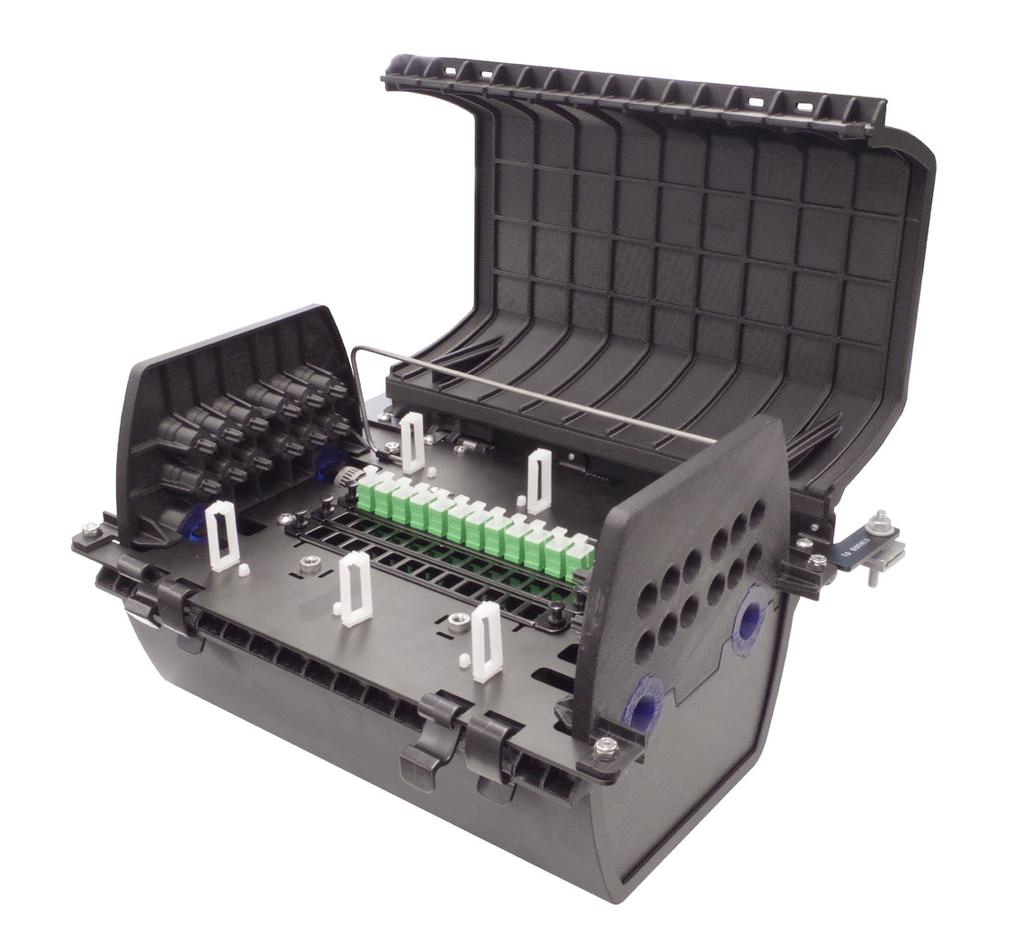
3 Installation Manual Application When the network deployment plan calls out for an aerial application, Clearfield s YOURx-Aerial Terminal application allows for the flexibility to terminate a feeder fiber, directly into revenue generating drops and has the capability to accommodate a fiber cable mid-span, allowing cables to be fully utilized while feeding multiple terminals and access points. Description Designed with many of the same features as the YOURx-Terminal, the YOURx-Aerial Terminal allows for aerial or strand mount fiber deployment within the network architecture. The YOURx-Aerial Terminal can accept the hand-off of fiber and distribute up to 24 individual service drops and has the capability to mid-span a larger count fiber cable, allowing the service provider to deploy multiple terminal/access points along the same cable run, maximizing the investment in fiber deployment. Designed for easy, craft accessibility, the YOURx-Aerial Terminal application has an upward hinging, kickstand supported cover with four side entrance cable access ports. Two individual compartments separate the incoming splices from the drop ports for network security. The backplane of the unit has the capacity to hold up to three splice trays, incorporating fiber management and bend-radius protection into the design. Each splice tray supports 24 loose tube or 72 ribbon splices. With up to 24 individual drops terminated to SC of LC connectors, the YOURx-Aerial Terminal can accept all of the FieldShield drop options, as well as other cable drop options. Technical Specifications YOURx-Aerial Terminal - Patch and Splice Dimensions W x H x 8.15 D (height includes strand bracket) Material Black UV resistant Thermoplastic Mounting Options Aerial or Strand Mount Internal Slack Storage Up to 8 feet of ribbon (144 fiber); up to 8 feet of loose tube (144 fiber) Feeder Ports Four silicone sealed ports on ends of unit; two on each end Distribution Ports Up to mm YOURx FlexPorts that accept FieldShield Microduct or FLEXdrop connectors Connector Types SC/APC, SC/UPC, LC/APC, LC/UPC Splicing Capabilities 24 loose tube or 72 ribbon splices per tray; three splice trays per terminal 3
 w/ Connectors (SC or LC) Top")


4 Installation Manual Components Fiber Drop Management Rings 24 Distribution FlexPorts 12 each per side Street Side View Field Side View Lid Kickstand Adapter Plate(s) w/ Connectors (SC or LC) Top row open for future use 2nd row for ports rd row for ports Strength Member Clamps 2 each per side Lid Kickstand Splice Tray Area Up to 3 Splice Trays Slack Management Rings Loose tube Slack Basket variant not shown Slack Capacity: 8FT Loose Tube, max 144 fibers 8FT Ribbon, max 144 fibers Mid-Span Capable GROUNDING AND BONDING: PER LOCAL PRACTICE Cable Clamp Locations 2 each per side 4


5 Installation Manual Parts List Hose Clamps (2) 2. Bug Nuts (2) 3. Ribbon Strain Relief (3 per Splice Tray) 4. Ribbon Splice Chip (2 per Splice Tray) 5. Splice Chip (2 per Splice Tray) 6. Half Grommets (8) 7. Splice Tray (up to 3) 8. End Plates (2) Optional Accessories 9. FlexPorts 10. Field Installabe FlexConnectors


6 Installation Manual Recommended Tools Tool Image Mid-Span Access Tool De-burring Tool Snips Pliers Optical End Face Cleaning kit Small Cable Ties Cable Opening Tools Can Wrench 6


7 Installation Manual Strand Mounting Mounting YOURx-Aerial Terminal to strand options: A: Using provided mounting brackets and bug nuts B: Using optional adjustable mounting bracket A: Provided Mounting Bracket B: Optional Bracket P/N:


8 Installation Manual Accessing the YOURx-Aerial Terminal Each side of the YOURx-Aerial Terminal has a lid which is secured by two tabs. Release the tabs on one side in order to open the lid on that side. Close the lid and snap the tabs into place to secure it back in place. The lid on each side of the YOURx-Aerial Terminal can be propped open with the attached kickstand. Push the kickstand back and seat it under the tabs on the inside of the lid to prevent the lid from closing while the terminal is in use. 8

.")


 the port hole for a")
9 Installation Manual Supports all FieldShield Drop Options Preparing FlexPorts for Drops The terminal is available in a 6, 12 or 24 port drop configuration. Ports 1-12 will be on the left end plate, typically closest to the serving pole (unless specified differently, at ordering). Ports on far end endplate Useable FlexPorts will be marked with a silver X on the inside of port tab, indicating that a FlexPort has been installed and capable of accepting a water tight FlexConnector or microduct. End Plate Interior End Plate Exterior Step 1: Using pliers, remove the tab from the desired port by bending and breaking the excess plastic away. Step 2: De-burr (using a de-burring tool/snips/ knife) the port hole for a smooth transition, helping to prevent damage to the fiber when it enters the port. 9
, creating a cone shape on the inside of the")


10 Installation Manual Installing Microduct and Push/Pull Fiber Drops Step 1: De-burr the microduct, using the de-burring tool or similar device (snips or cable knife), creating a cone shape on the inside of the microduct for a smooth transition. Step 2: Insert the pull string, if one is being utilized, through the FlexPort, and firmly seat the microduct into the FlexPort. Step 3: Tie the pull string to the bulkhead until you are ready to pull in a fiber drop. Step 4: After pulling fiber into terminal, complete the Pushable Connector housing as instructed with the specific connector being utilized. Step 5: Inspect Then Connect! Follow our recommended Connector Cleaning Procedures included in this manual for a reliable connection. Step 6: Make the connection to the assigned port. Step 7: Route slack around fiber drop management rings. 10

 into the FlexPort.")

11 Installation Manual Installing FLATdrop and D-ROP with FlexConnector IMPORTANT WARNING:DO NOT INSTALL CONNECTOR HOUSING UNTIL INSTRUCTED Step 1: Push the YOURx breakout with SC connector assembly (FLATdrop or D-ROP) through FlexPort. Step 2: Firmly seat the FlexConnector (FLATdrop or D-ROP) into the FlexPort. Step 3: After pulling fiber into terminal, complete the Pushable Connector housing as instructed. Step 4: Inspect Then Connect! Follow our recommended Connector Cleaning Procedures included in this manual for a reliable connection. Step 5: Route slack around fiber drop management rings. 11


12 Installation Manual Installing FlexPorts in the Field On the outside of terminal, at the desired port, insert the FlexPort pieces as shown. O-Ring Press-In Clip Step 1: Insert an O-ring into the desired port. Push the O-ring all the way into the port, as far back as it will go. Make sure it lies flat in the port. Step 2: Insert the Press-In piece into the port after the O-ring. Be sure to place the Press-In into the port tapered side first, with the teeth side facing outwards. Press hard or gently tap it into place with a tool, as needed, until it sits fully flush. Step 3: Install the Clip piece of the FlexPort into the Press-In. It should click into place. Once installed, Clips should be loose, not springy. If you notice the Clip being pushed out, re-adjust the O-ring. 12


 3/4 x 2 1/4")
 (1) 5/16 x 3 long (004458) Step")


13 Installation Manual Installing the Field Installable FlexConnector Step 1: Prep cable to YOURx length (14 inches) cutting strength members flush with black, outer cable sheath. Step 2: For water tight seal, feed the following three lengths of heat shrink onto cable for later use: (1) 3/4 x 2 1/4 long (004867) (1) 1/2 x 2 1/4 long (004644) (1) 5/16 x 3 long (004458) Step 3: Pass breakout 3mm cable through FlexConnector. Step 4: Stop short of cable sheath. Step 5: Align nose of clips to end of black cable and sandwich together. Step 6: Attach clips to top and bottom of cable, teeth in, even at cable sheath opening. A groove on the clip allows for proper alignment. Nose Teeth 13


 heat shrink tubing,")

 covering rear of clips and heat to shrink.")

14 Installation Manual Step 7: Use pliers (as shown) to pinch teeth to hold jacket. DO NOT use needle nose pliers. Step 8: Pull FlexConnector (added in Step 3) back over clips to snap into FlexConnector holes, as shown. Push until you hear a snap. Step 9: Slide the 3 piece (004458) heat shrink tubing, placing one end just inside the back end of the Flex- Connector. Shrink using a heat gun. FlexConnector Hole Step 10: Place smaller diameter heat shrink (004644) covering rear of clips and heat to shrink. Step 11: Finish with the largest heat shrink (004867) covering the holes on the FlexConnector and heat to shrink. This will create a water tight seal. Step 12: Terminate fiber to connector per instructions (if applicable). 14

 as shown.")
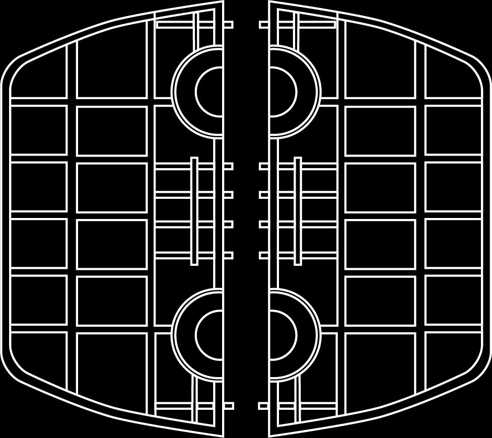
15 Installation Manual Preparing End Plates for Splicing Step 1: Locate the two end plates. Step 2: Position all four of the cable entrance ½ grommets in the end plates. Step 3: For each cable entrance that will be used, trim the compression grommet to fit the cable being utilized (up to ¾ inch outer diameter) as shown. Note: It may be easier to trim the grommets to size before inserting them into the end plates. 15
, 8 feet (96 inches) of slack and 3 feet (36 inches) for splicing in the splice tray.")
 you will be bringing in (max outer diameter 3/4 ).")
16 Installation Manual Preparing Fiber Cables for Splicing Step 1: Open the cable to expose the buffer tubes/ribbons for splicing, mid-spanning the cable if applicable. Note: Max cable opening for a 144 fiber loose tube cable will be 11 feet (132 inches), 8 feet (96 inches) of slack and 3 feet (36 inches) for splicing in the splice tray. Step 2: Trim the cable s strength member, on each end if mid-spanning, to approximately 3 inches. Step 3: Trim the remaining cable entrance 1/2 grommets to fit the cable(s) you will be bringing in (max outer diameter 3/4 ). If no cable will be present in an entrance location, leave the grommets untrimmed, but still insert them into their locations in the end plates. Step 4: Place the cable into the terminal at the chosen cable entrance/exit, making sure that the compression grommet is set into the end plate behind. Step 5: Slide the strength member into the clamp and secure it in place. Step 6: Place the provided hose clamp over the cable and tighten, securing it in place to the bulkhead. The cable jacket opening should be located at least 1/4 past the hose clamp. Note: If mid-spanning/expressing cable, complete steps 4-6 again on the other end of the cable opening. 16


 or rings (ribbon).")

17 YOURx-Aerial Terminal Installation Manual Step 7: Once all cables are loaded into terminal, place the end plates on each side of terminal. Placing the ribbed side of plate to the inside, press the end plate until it locks into place, ensuring the top and bottom 1/2 grommets are located in all 4 cable entrance locations. Step 8: From the newly installed cable bundle, remove the buffer tube/ribbons that will be spliced in the splice tray and set them aside. Store the remaining buffer tubes/ribbons in the slack management basket (buffer tubes) or rings (ribbon). Buffer Tube Ribbon Step 9: Store 2-3 wraps of the buffer tubes/ribbons you intend to splice, slack that will be used to bring the splice tray and fibers to your workspace and perform the splices. Step 10: Clearfield recommends an additional 3ft/1m of fiber after the 2-3 slack wraps, which will be used for splicing in the splice tray. Step 11: Remove the slack wraps of the ribbons/buffer tubes you intend to splice. 17


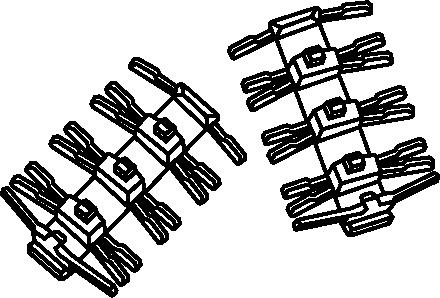
18 Installation Manual Splicing in the YOURx-Aerial Terminal Splice Tray Setup Splice trays (P/N ) will be shipped with 2 standard splice chips and 2 ribbon splice chips, allowing for a total of 24 loose tube splices or 6 ribbon mass fusion splices (72 fibers). Splice chips will need to be gently bent, placing both ends into the empty slots in the center of the splice tray. Note: Each standard splice chip features 6x2 splice sleeve slots, allowing for 12 splice sleeves to be stacked 2 high in the 6 slots. Each ribbon splice chip features 3 ribbons splice sleeve slots, as well as one 2 high loose tube splice sleeve slot for use in special applications or repairs. Splice Chip Ribbon Splice Chip Bending the Splice Chip Splice Tray Loaded with 2 Splice Chips Splice Tray Loaded with 2 Ribbon Splice Chips 18
 which will")


19 Installation Manual Ribbon Step 1: Bring the ribbon fibers you wish to splice to the splice tray in your workspace. Note: Provided with the splice tray are 3 ribbon tie-downs which utilize a split grommet and u-channel (plastic retention cover) which will allow the ribbon to be secured into the tray even in mid-span/ring cut applications. Step 2: 3ft from the end, slip the split rubber grommet onto the ribbon, followed by the u-channel over the opposite side. Note: Extra ribbon tie-downs are available in a kit, which can be ordered seperately (P/N ). Step 3: After protecting the ribbon fiber with the ribbon tiedown, secure it into the tray using small cable ties. Note: The splice tray features tie-down holes on each side of the tray, which will allow for 5 ribbon tie-downs per side, in addition to one ribbon tie down on each side in the assembly fiber location. Assembly Fiber Location Incoming Fiber Tie-Down Step 4: Remove the 5 meter ribbon fiber assembly that is wrapped around the center spools below the splice tray area and taped to the top. 24 fiber configurations will arrive with two 12 fiber ribbons. Step 5: Bring the fiber assembly to the splice tray in your workplace and secure it into the splice tray in the same manner as you did for your incoming ribbon fiber. Note: Clearfield recommends leaving 3ft/1m after the ribbon tie down for use in splicing in the splice tray. 19


 in place with the provided velcro strap and two wing")
20 Installation Manual Step 6: Perform your splices, securing the ribbon splice sleeves in the ribbon splice chips in the center of the splice tray. Step 7: Reinstall the splice tray cover. Step 8: Place the splice tray into the splice tray area, allowing the two threaded studs to pass through the holes on each side of the splice tray. Step 9: Re-store the extra slack used to reach your work space into the fiber management rings. Step 10: Secure the splice tray(s) in place with the provided velcro strap and two wing nuts, which will go on the two threaded studs. Note: The YOURx-Aerial Terminal can hold up to three splice trays. Step 11: Close the YOURx-Aerial Terminal, latching the lid shut. 20


21 Installation Manual Loose Tube Step 1: Bring the buffer tubes you wish to splice to the splice tray in your workspace. Note: A maximum of 24 loose tube splices can be completed in each splice tray. Step 2: Wrap one layer of grommet tape around the buffer tube, 3 feet (1 meter) back from the end of the tube. Trim the excess grommet tape. Step 3: Open the buffer tube roughly 1/4 inch after the grommet tape, being careful not to damage the loose tube fibers. Note: If expressing fibers in the buffer tube, remove approximately 3ft/1m of the buffer tube in a window, protecting the buffer tube on the other side with grommet tape in the same manner as shown here. Step 4: Using two small cable ties, secure the buffer tube into the splice tray. Note: When using cable ties/zip ties to secure fibers, do not use excessive force! Take care not to damage fibers. 21


22 Installation Manual Step 5: Remove the 5m pre-loaded fiber assembly from the central spools of the terminal and bring it to your workspace. Note: In loose tube splicing applications, the fiber assembly will consist of a 5m ribbon which as been de-laminated for the last meter, resulting in twelve 250 micron loose tube fibers which will be taped to the top of the splice tray area. Step 6: To secure the pre-loaded fiber assembly into the splice tray, refer back to the ribbon splicing section of this manual. You will be using the split grommet and u-channel to secure the ribbon, just before it is broken out into loose tube, into the splice tray. Step 7: Perform your splices, stacking the splice sleeves two high in the splice chips located in the center of the splice tray. Step 8: After splicing is complete, replace the splice tray cover. Step 9: Bring the splice tray back to the YOURx-Aerial Terminal, placing the splice tray into the terminal by sliding the two mounting holes on the tray over the two threaded studs in the splice tray area. Note: Consult the ribbon splicing section of this manual for images. Step 10: Route the excess slack, which was used to access the work space, back into the slack basket surrounding the splice tray area of the terminal. Step 11: Secure the splice tray(s) (up to 3) in place with the provided velcro strap and two wing nuts, which will go on the two threaded studs. Step 12: Close the YOURx-Aerial Terminal, latching the lid shut. 22


23 Installation Manual 6 Fiber 900 Micron Assembly Step 1: Gather the six 900µm fibers and measure approximately 3ft/1m from the end. Mark the fibers with a permanent marker. Step 2: Fold a piece of grommet tape around the fibers at the mark you made, and trim the excess. Step 3: Place two small cable ties into the holes in the splice tray on the side you wish to secure the assembly. Note: You will mirror all these steps being done for your incoming fibers with the pre-loaded fiber assembly. Step 4: GENTLY secure the bundle of 900µm fibers into the tray. DO NOT secure too tightly or you will damage the fibers. Step 5: Perform your splices, stacking splice sleeves in the splice chip in the center of the splice tray. Step 6: Replace the splice tray cover. Place the splice tray back into the terminal, sliding the holes in the splice tray over the two threaded studs in the splice tray area. Note: Refer to the ribbon splicing section of this manual for images showing these steps. Step 7: Route the excess slack used to reach the work space back into the YOURx-Aerial Terminal. Step 8: Secure the splice tray(s) (up to 3) back into the terminal with the provided velcro and wing nuts on each threaded stud. Step 9: Close the YOURx-Aerial Terminal, latching the lid shut. 23


/ Outdoor Yes -40 to 176 F Yes Black/ White Yes For use when a")
 Outdoor in Duct Yes in Duct -40 to 176 F Yes Black Yes For use when the distance")

24 Installation Manual DROP CABLE OPTIONS Product Name FieldShield FLATdrop Cable Jacket UV Temperature FieldShield Connector Jacket Color Can be stapled Outdoor Yes -40 to 176 F No Black Yes Best Application For use when fast installation and low up-front cost is most desired feature. FieldShield D-ROP Outdoor Yes -40 to 176 F Yes Black/ Orange Yes For use when a single pass and restorable solution at a competitive price is ideal. FieldShield FLEXdrop Indoor (Plenum)/ Outdoor Yes -40 to 176 F Yes Black/ White Yes For use when a premium product that has maximum workability, flexibility and restorability is desired. FieldShield (Classic) Outdoor in Duct Yes in Duct -40 to 176 F Yes Black Yes For use when the distance from the access point to the SFU/MDU is longer than normal and a more rigid solution is required to maintain restorability for drops longer than 300 feet. FieldShield StrongFiber Indoor/ Outdoor in Duct Yes in Duct -40 to 176 F Yes Black Yes in Duct For use when a reusable pathway is needed and maximum slack storage is desirable. 24


25 Installation Manual Connector Cleaning Procedure Whether factory terminated or field spliced, clean connectors are essential for proper system operation. Even the smallest dust particle can cause transmission problems, so for optimal network performance inspect, and if necessary, clean connectors and adapters prior to mating. Inspect Then Connect These are Clearfield recommended products/applications. Use the product you feel will complete your cleaning procedures. Create a best practice for your company and follow those procedures. The use of Chemtronics end face and bulkhead cleaning products and techniques ensures a clean end face, no matter the type of contamination. Before cleaning any connector, be sure you know what type of contaminate you are cleaning (dry, fluidic, or combination). All the available products are good, it s the process that you need to be aware of. Using a dry cleaning method to clean dirt can lead to scratching of the end face. Learn the process of cleaning properly. Figure 1 Note: It is NOT recommended to use isopropyl alcohol to clean the end face. Cleaning an SC/LC Connector Cleaning the End Face Place one wiping paper on QbE-2 FiberSafe Cleaning Platen. (Figure 1) Apply small amount of precision cleaner (about 1 in diameter) with Electro-Wash MX pen on to one end of the wipe. (Figure 2) Figure 2 Hold end face at a 90 degree angle. For APC connection, adjust by slightly tilting the container or end face. Angle is correct when no drag is felt on the end face. (Figure 3) Draw end face from wet to dry part of the wipe 3 times. Use just enough pressure to ensure complete contact between end face and the wipe. Note: DO NOT retrace previous step. Figure 3 25
 by spotting a small amount (about 1 ) of Electro-Wash PX or Electro-Wash MX pen onto the QbE. Hold the swab, 1 side down to the wetted area and hold for a count of 1-2-3-4-5.")
 Cleaning the Mate Through an Adapter AND the Adapter Itself Figure 5 Lightly moisten the fiber optic swab (2.5mm/38542F or 1.")

26 Installation Manual Cleaning the Ferrule Lightly moisten the fiber optic swab (2.5mm/38542F or 1.25mm/38040) by spotting a small amount (about 1 ) of Electro-Wash PX or Electro-Wash MX pen onto the QbE. Hold the swab, 1 side down to the wetted area and hold for a count of (Figure 4) Figure 4 Insert swab into side of ferrule, wet side to the ceramic ferrule and circle around 2-3 times and remove. Turn swab to dry side and repeat. (Figure 5) Cleaning the Mate Through an Adapter AND the Adapter Itself Figure 5 Lightly moisten the fiber optic swab (2.5mm/38542F or 1.25mm/38040) by spotting a small amount (about 1 ) of Electro-Wash PX or Electro-Wash MX pen onto the QbE. Hold the tip of the swab onto the wetted area and hold for a count of Insert the swab into the adapter to the connector, press lightly against the connector, twist 2-3 times, remove and discard. Dry with a second dry swab. Inspect, repeat cleaning if necessary, and test for signal strength. Use additional swabs to clean inside the actual adapter. Moisten swab, like above, and insert through hole and remove while twisting. (Figure 6) Figure 6 26
 Figure 1 Hold end face at a 90 degree angle. For APC connection, adjust by slightly tilting the container or end face.")
 Male Connector Figure 2 Lightly moisten one side of the fiber optic swab (CC505F) by spotting a small amount (about 1 ) of Electro-Wash PX or Electro-Wash MX pen onto the QbE.")
27 Installation Manual Cleaning an MPO/MTP Connector Female Connector Place one wiping paper on QbE-2 FiberSafe Cleaning Platen and apply small amount of precision cleaner (about 1 in diameter) with Electro-Wash MX pen on to one end of the wipe. (Figure 1) Figure 1 Hold end face at a 90 degree angle. For APC connection, adjust by slightly tilting the container or end face. Angle is correct when no drag is felt on the end face. (Figure 2) Male Connector Figure 2 Lightly moisten one side of the fiber optic swab (CC505F) by spotting a small amount (about 1 ) of Electro-Wash PX or Electro-Wash MX pen onto the QbE. Hold the swab, 1 side down to the wetted area and hold for a count of Place swab, wet side down, at one end of connector end face and draw across in a diagonal sweep; i.e., from fiber 1 up and across to fiber 12. Turn swab over to dry and draw back from fiber 12 to fiber 1. (Figure 3) Figure 3 27
28 Installation Manual Standard Warranty Clearfield warrants to the original purchaser of the Product sold hereunder is free from defects in material and workmanship under normal use and service, subject to exceptions stated herein. Product purchased is warranted as follows: Clearfield designed and branded Products are warranted for three (3) years: Products manufactured by Clearfield to customer prints and/or specifications are warranted for one (1) year; and any Product Clearfield acquires from or through a third-party manufacturer or distributor and resells to Customer as the original customer will carry the manufacturer s pass-through warranty, if any. In all cases, the warranty period commences on the date of shipment to the original purchaser. Warranty Claim Procedure If any Product purchased from Clearfield is found defective under the above warranty, the following basic procedure must be followed: 1. Customer must contact Clearfield and obtain a Return Materials Authorization. 2. Following authorization, the Customer ships the product-freight collect-to Clearfield s manufacturing facility. 3. Clearfield shall repair or replace the defective Product at its sole option and discretion, and return the repaired or replacement Product to Customer s site, freight prepaid. Note: If the Product is not found to be defective by Clearfield, the product will be returned to the Customer and the customer billed for freight in both directions. View our warranty policy here: Limitations of Warranty Correction of defects by repair or replacement, at the option of Clearfield Inc, shall constitute the exclusive sole remedy for a breach of this limited warranty. Clearfield shall not be liable under any circumstances for any special, consequential, incidental, punitive, or exemplary damages arising out of or in any way connected with the product or with agreement to sell product to buyer, including, but not limited to damages for lost profits, loss of use, or for any damages or sums paid by buyer to third parties. The foregoing limitation of liability shall apply whether the claim is based upon principles of contract, warranty, negligence or other tort, breach of statutory duty, principles of indemnity or contribution, the failure of any limited or exclusive remedy to achieve its essential purpose, or otherwise. Clearfield will not be responsible for any labor or materials costs associated with installation or incorporation of Clearfield products at customer sites, including any costs of alteration, replacement or defective product, or any field repairs. Other Limitations Clearfield assumes no warranty liability regarding defects caused by: 1. Customer s modification of Product, excepting installation activities described in Clearfield documentation. 2. Customer re-packaging of Product for shipment to third parties or destinations other than those originally shipped to by Clearfield, or any defects suffered during shipping where the Product has been re-packaged. 3. Customer s installation or maintenance, excepting activities described in and performed in accordance with Clearfield documentation 4. Customer s improper or negligent use or application of Product. 5. Other causes external to the Product, including but not limited to accidents, catastrophe, acts of God, government action, war, riot, strikes, civil commotion, sovereign conduct, or the acts or conduct of any person or persons not party to or associated with Clearfield. 6. Environmental factors and weathering resulting in aging and damage not necessary or applicable to the function of the product. 28
29 Installation Manual Proprietary Notice Information contained in this document is copyrighted by Clearfield, Inc. and may not be duplicated in full or part by any person without prior written approval of Clearfield, Inc. Its purpose is to provide the user with adequately detailed documentation to efficiently install the equipment supplied. Every effort has been made to keep the information contained in this document current and accurate as of the date of publication or revision. However, no guarantee is given or implied that the document is error free or that it is accurate with regard to any specification. Technical Support Clearfield, Inc. can be contacted for any issues that arise with the supplied product. If you need to return the supplied product, you must contact the Clearfield, Inc. Customer Service Department to request a Returned Materials Authorization (RMA) number. Clearfield, Inc Winnetka Ave N Minneapolis, MN Toll Free: Phone: Fax: Customer Support: sales@clfd.net Technical Support: techsupport@clfd.net 29
CraftSmart Test Access Point (TAP) Box Installation Manual
 Box Installation Manual") Installation Manual Installation Manual Table of Contents Application 3 Description 3 Technical Specifications 3 TAP Box Assembly 4 TAP Box Mounting 8 Cable Entrance 10 Grounding 11 Strength Member Clamp
Installation Manual Installation Manual Table of Contents Application 3 Description 3 Technical Specifications 3 TAP Box Assembly 4 TAP Box Mounting 8 Cable Entrance 10 Grounding 11 Strength Member Clamp
FieldShield YOURx-TAP Installation Manual
 Installation Manual Installation Manual Table of Contents Product Packaging 3 Parts List 3 Required Tools 4 Box Mounting 4 Preparing Ports 5 Bottom Deploy Reel Installation 5 Configurations 8 Top Deploy
YOURx Flex Box Installation Manual
 Installation Manual Installation Manual Table of Contents Recommended Tools 3 Parts List 4 Components: Aggregator Plates 5 Ship along Items 6 Using the Flex Box with Drop Wheels (Max 16) 8 Using the Flex
Be sure to read and completely understand this procedure before applying product. Be sure to select the proper PREFORMED product before application.
 5 NOVEMBER 2010 COYOTE Dome 9.5 x 28 Be sure to read and completely understand this procedure before applying product. Be sure to select the proper PREFORMED product before application. 1. 7. 2. 4. 10.
Fiber Splice Panel Rack Mount User Manual
 Fiber Splice Panel Rack Mount User Manual Content Page INTRODUCTION... 1 Revision History... 1 List of Changes... 1 Trademark Information... 2 Admonishments... 2 1. DESCRIPTION... 2 A. Product Definition
COYOTE 28" GLC (Ground Level Closure) Complete Assembly Installation
 Complete Assembly Installation") NOVEMBER 2016 COYOTE 28" GLC (Ground Level Closure) Complete Assembly Installation Be sure to read and completely understand this procedure before applying product. Be sure to select the proper PREFORMED
NOVEMBER 2016 COYOTE 28" GLC (Ground Level Closure) Complete Assembly Installation Be sure to read and completely understand this procedure before applying product. Be sure to select the proper PREFORMED
8400 Series Fiber Distribution System
 8400 Series Fiber Distribution System Instructions January 1997 34-7041-4699-1-A 1 Contents: 1.0 General... 3 2.0 System Components... 4 3.0 System Engineering... 5 4.0 Hardware Installation... 7 5.0 Cable
CS Fiber Optic Splice Case. Instruction
 3 2179-CS Fiber Optic Splice Case Instruction 2179-CS Fiber Optic Splice Case Description 1.0 General 1.1 The 3M 2179-CS Fiber Optic Splice Cases are closures that can be used in buried, underground, aerial,
COYOTE Dome Closure 9.5" x 28" with Transition Tray for High Density Splice Applications
 OCTOBER 2017 COYOTE Dome Closure 9.5" x 28" with Transition Tray for High Density Splice Applications Be sure to read and completely understand this procedure before applying product. Be sure to select
3M Fiber Dome Closure FDC 10
 3M Fiber ome losure F 10 With 3M Fiber Optic Splice Tray 2541 Instructions 1.0 General 2.0 Kit ontents The 3M Fiber ome losure F 10 can accommodate two 1.06" (27 mm) main cables, five 0.71" (18 mm) branch
COYOTE Dome Cross-Connect Closure 6-1/2" x 22"
 FEBRUARY 2015 COYOTE Dome Cross-Connect Closure 6-1/2" x 22" Be sure to read and completely understand this procedure before applying product. Be sure to select the proper PREFORMED product before application.
COYOTE 9.5" x 19" (292 mm x 509 mm) Dome Closure
 Dome Closure") AUGUST 2012 COYOTE 9.5" x 19" (292 mm x 509 mm) Dome Closure Be sure to read and completely understand this procedure before applying product. Be sure to select the proper PREFORMED product before application.
AUGUST 2012 COYOTE 9.5" x 19" (292 mm x 509 mm) Dome Closure Be sure to read and completely understand this procedure before applying product. Be sure to select the proper PREFORMED product before application.
COYOTE Dome Closure 6.5" x 22" Kits. COYOTE Dome Closure 6.5" x 22" for Buffer Tube Applications. Includes: (2) Grommets, (1) Buffer
 Grommets, (1) Buffer") JANUARY 2015 COYOTE Dome Closure 6.5" x 22" Be sure to read and completely understand this procedure before applying product. Be sure to select the proper PREFORMED product before application. 1 2 3 6
JANUARY 2015 COYOTE Dome Closure 6.5" x 22" Be sure to read and completely understand this procedure before applying product. Be sure to select the proper PREFORMED product before application. 1 2 3 6
JANUARY 2015 NOMENCLATURE. TOOLS REQUIRED 3/8" & 7/16" Can wrench or socket 1/4 Nut driver or screwdriver Snips Fiber optic cable opening tools
 JANUARY 2015 COYOTE Dome Closure 6-1/2" x 17" Be sure to read and completely understand this procedure before applying product. Be sure to select the proper PREFORMED TM product before application. 1 2
EZ-R7 T-Plug. Universal 7-Pin Heavy Duty Plug For Vehicles equipped with 7-Way Trailer Connectors. Installation Instructions and Product Warranty
 EZ-R7 T-Plug Universal 7-Pin Heavy Duty Plug For Vehicles equipped with 7-Way Trailer Connectors Installation Instructions and Product Warranty Professional Installation Required Thank you for purchasing
Adjustable Angled Incline Conveyor Owners Manual with Operating Instructions
 Adjustable Angled Incline Conveyor Owners Manual with Operating Instructions Revision 012211 Table of Contents Basic Conveyor Features 3 Getting Started 4 Setting Up the Incline Conveyor 5 Belt Removal
COYOTE 9.5" x 19" (292 mm x 509 mm) Cross-Connect Dome Closure
 Cross-Connect Dome Closure") AUGUST 2013 COYOTE 9.5" x 19" (292 mm x 509 mm) Cross-Connect Dome Closure Be sure to read and completely understand this procedure before applying product. Be sure to select the proper PREFORMED TM product
AUGUST 2013 COYOTE 9.5" x 19" (292 mm x 509 mm) Cross-Connect Dome Closure Be sure to read and completely understand this procedure before applying product. Be sure to select the proper PREFORMED TM product
HONDA RIDGELINE INSTALLATION INSTRUCTIONS. (866) RETRACTABLE TRUCK BED COVERS TABLE OF CONTENTS SWH2-1610
 RETRACTABLE TRUCK BED COVERS TABLE OF CONTENTS SWH2-1610") RETRACTABLE TRUCK BED COVERS HONDA RIDGELINE INSTALLATION INSTRUCTIONS TABLE OF CONTENTS SWH2-1610 (866) 338-3697 www.paceedwards.com Pace Edwards Company 2400 Commercial Blvd. Centralia WA 98531 Tools
RETRACTABLE TRUCK BED COVERS HONDA RIDGELINE INSTALLATION INSTRUCTIONS TABLE OF CONTENTS SWH2-1610 (866) 338-3697 www.paceedwards.com Pace Edwards Company 2400 Commercial Blvd. Centralia WA 98531 Tools
INSTALLATION INSTRUCTIONS
 TABLE OF CONTENTS GENERAL...2 SPECIFICATIONS...2 PACKAGE CONTENTS...2 PACKAGE CONTENTS: ACCESSORIES...3 REQUIRED TOOLS...3 ADD-ON COMPONENTS...3 CLOSURE MOUNTING...3 LOCK AND UNLOCK EXTERIOR DOOR...3 CABLE
COYOTE Terminal Dome Closure 6.5" x 22"
 FEBRUARY 2015 COYOTE Terminal Dome Closure 6.5" x 22" Be sure to read and completely understand this procedure before applying product. Be sure to select the proper PREFORMED product before application.
Fabric Replacement Top and Doors with Tinted Side and Rear Curtains Installation Instructions
 Fabric Replacement Top and Doors with Tinted Side and Rear Curtains Installation Instructions For: Wrangler/TJ 1997-2002 Part Number: 51124 www.bestop.com DO NOT INSTALL THIS PRODUCT ON ANY VEHICLE OTHER
SLiC Aerial Terminal and Spiral End Seal for use with AMP* Quiet Front Terminal Blocks
 SLiC Aerial Terminal and Spiral End Seal for use with AMP* Quiet Front Terminal Blocks Instructions June 2002 78-8130-2161-1-B 1 Contents: 1.0 General... 3 2.0 Kit Contents... 3 3.0 Cable Preparation...
RAM BOX INSTALLATION SHEET
 RAM BOX INSTALLATION SHEET Any damaged or missing parts? Parts will be shipped to you directly. Call 844-779-8986 Mon - Fri 8:30 am - 7 pm EST or email support@bakindustries.com 6.5 bed Front (cab) 5.5
Read all instructions before installing and using. Installer: This manual must be delivered to the end user.
 Installation Instructions Vacuum / Magnet Mount Kits IMPORTANT! Read all instructions before installing and using. Installer: This manual must be delivered to the end user.! WARNING! Failure to install
MARCH COYOTE 9.5 x 19 (292 mm x 509 mm) Terminal Dome Closure Kits
 Terminal Dome Closure Kits") MARCH 2012 COYOTE 9.5 x 19 (292 mm x 509 mm) Terminal Dome Closure Be sure to read and completely understand this procedure before applying product. Be sure to select the proper PREFORMED product before
MARCH 2012 COYOTE 9.5 x 19 (292 mm x 509 mm) Terminal Dome Closure Be sure to read and completely understand this procedure before applying product. Be sure to select the proper PREFORMED product before
LPC Series Fiber Panel 12/24 Fiber Rack-Mount Enclosure Installation Instructions
 LPC Series Fiber Panel 12/24 Fiber Rack-Mount Enclosure Installation Instructions ADCP-92-129 Issue 1 6/2010 Content Page INTRODUCTION.............................................................................
AGCO. Corn Header Manual d HEADSIGHT.COM
 AGCO Corn Header Manual 09020401d HEADSIGHT.COM 574.546.5022 About Headsight Headsight Contact Info Headsight, Inc. 4845 3B Road Bremen, IN 46506 Phone: 574-546-5022 Fax: 574-546-5760 Email: info@headsight.com
12-Inch Hybrid Fiber Access Terminal Installation Instructions
 12-Inch Hybrid Fiber Access Terminal Installation Instructions 19683-A Content Page 1 PRODUCT DESCRIPTION.................................................................. 2 2 PRODUCT FUNCTION.....................................................................
Installation Instructions Supertop for Truck
 Installation Instructions Supertop for Truck Vehicle Application: Ford F-150 5.5 Ft. Styleside 2004 and newer Part Number: 76309 www.bestop.com - We re here to help! Visit our web site and click on Ask
Installation Instructions for Drapery System Drapery
 Installation Instructions for Drapery System 5060 Drapery - 5060 Table of Contents Tools Required: Power Screwdriver w/phillips bit Installing the 5060.............................. 3 Splicing the 5060...............................4
FIST-GSS2 FIST-GSS3. Fist Generic Splicing Shelf. Contents. 1 Introduction. 2 General. 3 Installation of the shelf. 5 Termination of the pigtails
 FIST-GSS2 FIST-GSS3 I N S T A L L A T I O N I N S T R U C T I O N Fist Generic Splicing Shelf Contents 1 Introduction 2 General 2.1 Kit content 2.2 Tools 3 Installation of the shelf 3.1 Mounting the shelf
Level Alert Model Multi-Switch Liquid Level Sensor. Assembly and Installation Instructions
 Level Alert Model 2000 Multi-Switch Liquid Level Sensor Assembly and Installation Instructions Kit Form Each unit is provided in kit form with step-by-step instructions, making it extremely easy to custom
CRD610 Automatic Fitting Inserter
 CRD610 Automatic Fitting Inserter OPERATIONS MANUAL VERSION 1.2 LAST EDITED 12.12.2018 cleanroomdevices.com 1 Table of Contents Title Page. 1 Table of Contents...2 1.0 General Product & Safety Information....3
INSTALLATION INSTRUCTIONS
 INSTALLATION INSTRUCTIONS Thank you for purchasing ACCESS Original Roll-Up Cover. Agri-Cover, Inc. proudly manufactured this cover using superior quality materials and workmanship. With proper care, your
COYOTE STP (Service Termination Point)
") JANUARY 2017 COYOTE STP (Service Termination Point) Be sure to read and completely understand this procedure before applying product. Be sure to select the proper PREFORMED product before application.
JANUARY 2017 COYOTE STP (Service Termination Point) Be sure to read and completely understand this procedure before applying product. Be sure to select the proper PREFORMED product before application.
FOSC-400D5 INSTALLATION INSTRUCTION. Fibre Optic Splice Closure with integrated organiser system
 FOSC-400D5 INSTALLATION INSTRUCTION Fibre Optic Splice Closure with integrated organiser system 1 General 1.1 The installation instruction describes the necessary steps to install the FOSC-400D5. The
CRD600 Automatic Fitting Inserter
 CRD600 Automatic Fitting Inserter OPERATIONS MANUAL VERSION 2.3 LAST EDITED 12.07.2018 cleanroomdevices.com 1 Table of Contents Title Page.. 1 Table of Contents. 2 1.0 General Product & Safety Information...3
Replay Fabric Replacement Top
 Replay Fabric Replacement Top Installation Instructions For: GEO Tracker, Suzuki Sidekick Part Number: 51137 & Vitara 1986-1994 WARNING This product is designed to enhance the appearance of the vehicle
COYOTE STP (Service Termination Point)
") March 2019 COYOTE STP (Service Termination Point) Be sure to read and completely understand this procedure before applying product. Be sure to select the proper PREFORMED TM product before application.
March 2019 COYOTE STP (Service Termination Point) Be sure to read and completely understand this procedure before applying product. Be sure to select the proper PREFORMED TM product before application.
COYOTE LCC (Low Count Closure)
") PLP Feature Focus 2009 Preformed Line Products OCTOBER 2012 Film available at www.preformed.com COYOTE LCC (Low Count Closure) Be sure to read and completely understand this procedure before applying product.
PLP Feature Focus 2009 Preformed Line Products OCTOBER 2012 Film available at www.preformed.com COYOTE LCC (Low Count Closure) Be sure to read and completely understand this procedure before applying product.
LoadMaxx. Installation Guide. For Air Ride Trailers. Air-Weigh Customer Support: PN R0
 LoadMaxx Installation Guide For Air Ride Trailers Air-Weigh Customer Support: 888-459-3247 PN 901-0158-000 R0 x1 Table of Contents LoadMaxx Trailer Overview...1 Installation Overview...1 Mounting the Scale...2
GERINGHOFF. Corn Header Manual f HEADSIGHT.COM
 GERINGHOFF Corn Header Manual 09020701f HEADSIGHT.COM 574.546.5022 About Headsight Headsight Contact Info Headsight, Inc. 4845 3B Road Bremen, IN 46506 Phone: 574-546-5022 Fax: 574-546-5760 Email: info@headsight.com
Crimp & Cleave Termination Instructions
 Your Optical Fiber Solutions Partner Crimp & Cleave Termination Instructions for 50 and 62.5 µm GiHCS, 200 µm HCS LC Connectors For Use With: 50 and 62.5 µm GiHCS 2.2 mm Fiber Optic Cables 200 µm HCS 2.2
CLEAN ROOM DEVICES, LLC "WHERE TUBING AND FITTINGS COME TOGETHER"
 CLEAN ROOM DEVICES, LLC "WHERE TUBING AND FITTINGS COME TOGETHER" CRD600 Automatic Fitting Inserter OPERATIONS MANUAL VERSION 2.1 LAST EDITED 7.25.14 DOCUMENT NUMBER 001 cleanroomdevices.com 1 Table of
THE SB01 SPLICE ENCLOSURE NOW INCLUDES A LID GASKET THAT DOES NOT REQUIRE RTV APPLICATION.
 THE SB01 SPLICE ENCLOSURE NOW INCLUDES A LID GASKET THAT DOES NOT REQUIRE RTV APPLICATION. DO NOT APPLY RTV TO THE GASKET WHEN SEALING THE SB01 SPLICE ENCLOSURE. SEE SECTION 18 FOR UPDATED INSTRUCTIONS.
Installation Instructions Trektop NX Twill
 Installation Instructions Trektop NX Twill Vehicle Application: Jeep Wrangler TJ 1997 2006 Part Number: 56920 www.bestop.com - We re here to help! Visit our web site and click on Ask a Question. Click
Installation Instructions Supertop NX
 Installation Instructions Supertop NX Vehicle Application: Jeep Wrangler JK 2 Door 2007 Current Part Number: 54722 www.bestop.com - We re here to help! Visit our web site and click on Ask a Question. Click
FIBER CONNECTOR SAFETY WARNINGS
 FIBER CONNECTOR SAFETY WARNINGS SAFETY INFORMATION 1. Always wear safety glasses. 2. Isopropyl alcohol is flammable and may cause eye irritation. In case of contact with eyes, flush with water for at least
Installation Instructions Supertop for Truck
 Installation Instructions Supertop for Truck Vehicle Application: Toyota Tacoma Double Cab 2005 - Current (5 ft.) Part Number: 76308 US Patent 6827391 www.bestop.com - We re here to help! Visit our web
Installation Instructions Trektop NX
 Installation Instructions Trektop NX Vehicle Application: Jeep Wrangler (JK) 2 Door 2007 Current Part Number: 56822 www.bestop.com - We re here to help! Visit our web site and click on Ask a Question.
Installation Instructions Twill Replace-a-top
 Installation Instructions Twill Replace-a-top Upper Door Skins Not Included Vehicle Application Jeep Wrangler TJ 2003-2006 Tinted Glass Windows Part Number: 79841 www.bestop.com - We re here to help! Visit
Installation Instructions
 Installation Instructions Trektop Doors not included Vehicle Application Jeep Wrangler Unlimited 2007 2011 Part Number: 56805 www.bestop.com - We re here to help! Visit our web site and click on Ask a
COYOTE CLOSURE ADOBE SERIES FOR UNDERGROUND, AERIAL, AND BURIED SPLICES 6.0" x 22" 8.5" x 22" (152.4 mm x mm mm x 558.
 FEBRUARY 2000 COYOTE CLOSURE ADOBE SERIES FOR UNDERGROUND, AERIAL, AND BURIED SPLICES 6.0" x 22" 8.5" x 22" (152.4 mm x 558.8 mm 215.9 mm x 558.8 mm) Be sure to read and completely understand this procedure
DRAGO. Corn Header Manual f HEADSIGHT.COM
 DRAGO Corn Header Manual 09020801f HEADSIGHT.COM 574.546.5022 About Headsight Headsight Contact Info Headsight, Inc. 4845 3B Road Bremen, IN 46506 Phone: 574-546-5022 Fax: 574-546-5760 Email: info@headsight.com
CLEAN ROOM DEVICES, LLC "WHERE TUBING AND FITTINGS COME TOGETHER"
 CLEAN ROOM DEVICES, LLC "WHERE TUBING AND FITTINGS COME TOGETHER" CRD600AF Automatic Fitting Inserter With Auto Feed OPERATIONS MANUAL (Shown with optional alcohol dispenser) 1 VERSION 1.1 LAST EDITED
INSTALLATION INSTRUCTIONS
 144F TABLE OF CONTENTS GENERAL... 2 SPECIFICATIONS... 2 PACKAGE CONTENTS... 2 PACKAGE CONTENTS: ACCESSORIES... 3 REQUIRED TOOLS... 3 ADD-ON COMPONENTS... 3 CABINET MOUNTING WALL MOUNT BRACKET ATTACHMENT...
Model P-40 & Model P-25 POWER PUSHER
 Power Pusher Description INSTRUCTION MANUAL The Power Pusher provides ram capability by using the spreading power of the POWER HAWK P-16 Rescue Tool. (The Power Pusher may also be used with other spreader
Installation Instructions Supertop for Truck
 Installation Instructions Supertop for Truck Vehicle Application: Ford F-150 Regular / Super Cab 2004 2011 (6.5 ft.) Part Number: 76305 US Patent 6827391 www.bestop.com - We re here to help! Visit our
EASY CONNECT CRANE KIT Festoon Conductor Systems
 ASSEMBLY INSTRUCTION MANUAL EASY CONNECT CRANE KIT Festoon Conductor Systems October, 2005 Copyright 2005, Yale Lift-Tech, division of Columbus McKinnon Corporation Part No. 117463-05 Mounting Instructions
Half Door Installation Instructions
 Half Door Installation Instructions For: CJ5 (1976-1983) Part Number: 53027 Congratulations on your purchasing decision. Bestop designed these Doors to give you years of dependability and performance with
Installation Instructions
 by Installation Instructions For: CJ5 (1955-1975) and M38, A1 (1951-1971) Part Number 51405 WARNING This product is designed primarily to enhance the appearance of the vehicle and to shield the occupants
INSTALLATION INSTRUCTION & OWNER S MANUAL
 CS-2500 & CS-2500P Water Filtration System INSTALLATION INSTRUCTION & OWNER S MANUAL Ver 1.2 All Rights Reserved APEC Water Systems Please keep this Owner s Manual for future reference. It contains useful
Make sure the rail is clamped square as shown. Start at the front, and place the first clamp approx 6 to 9 inches back.
 INSTALLATION SHEET Any damaged or missing parts? Parts will be shipped to you directly. Call 844-779-8986 Mon - Fri 5:30 am - 4 pm Pacific Time TOOLS RECOMMENDED 9/16 Wrench or socket 7/8 Drill bit & drill
Installation Instructions Trektop NX
 Installation Instructions Trektop NX Vehicle Application: Jeep Wrangler TJ 1997 2006 Part Number: 56820 www.bestop.com - We re here to help! Visit our web site and click on Ask a Question. Click here for
Installation Instructions Tigertop
 Installation Instructions Tigertop Vehicle Application Jeep CJ5 1955 1975 Part Number: 51405 Jeep M38, A1 1951 1971 Part Number: 51405 www.bestop.com - We re here to help! Visit our web site and click
Installation Instructions Trektop NX
 Installation Instructions Trektop NX Vehicle Application: Jeep Wrangler (JK) 2 Door 2007 Current Part Number: 56822 www.bestop.com - We re here to help! Visit our web site and click on Ask a Question.
2 Hours. Skill Level. 1 - Easy
 Installation Instructions Window Kit for Trektop NX Twill Vehicle Application: Jeep Wrangler Unlimited (JK) 4 Door 2007 Current Part Number: 58423 Installation Tips Before you begin installing your new
This sheet must be read completely to:
 Instalation Preparation This sheet must be read completely to: 2. Avoid causing injury to installer, customer, end user, or others. 3. Prevent damage to ATV, UTV, and Motorcycle and/or accessory. 4. Prevent
Installation Instructions Trektop
 Installation Instructions Trektop Vehicle Application Jeep Wrangler (JK) Unlimited 2007 Current Part Number: 56805 www.bestop.com - We re here to help! Visit our web site and click on Ask a Question. Click
International Scout Traveler Installation Instructions
 International Scout Traveler Installation Instructions Tools needed: 9/64 drill bit 1/8 drill bit #2 Philips bit for drill Tape measure Pencil Drill #3 Philips Screwdriver #2 Philips Screwdriver Utility
CORN HEADER MANUAL: CNH PRE-2012
 CORN HEADER MANUAL: CNH PRE-2012 09020201c HEADSIGHT.COM 574.546.5022 About Headsight Headsight Contact Info Headsight, Inc. 4845 3B Road Bremen, IN 46506 Phone: 574-546-5022 Fax: 574-546-5760 Email:
UltraGroove Electric
 UltraGroove Electric Electric Retractable Tonneau Covers INSTALLATION INSTRUCTIONS CHEVROLET SILVERADO/SIERRA TABLE OF CONTENTS (800) 338-3697 www.paceedwards.com Pace Edwards Company 2400 Commercial Blvd.
Installation Instructions Table of Contents
 Installation Instructions Table of Contents Pre- Installation of Garage Storage Lift 2 Layout the Garage Storage Lift 3 Installing the strut Channels 3 Install the Drive Assembly 5 Install the Drive Shaft
Installation Instructions Supertop NX Twill
 Installation Instructions Supertop NX Twill Vehicle Application: Jeep Wrangler Unlimited 2007 Current Part Number: 54823 www.bestop.com - We re here to help! Visit our web site and click on Ask a Question.
INSTALLATION & OPERATING INSTRUCTIONS: REVOLUTION SPINEBOARD ATTACHMENT WARNING
 INSTALLATION & OPERATING INSTRUCTIONS: REVOLUTION SPINEBOARD ATTACHMENT LOAD CAPACITY: 500 LBS [227 kg] MANDATORY: LEAVE THIS MANUAL WITH LIFT OWNER WARNING 1. READ AND FOLLOW ALL INSTRUCTIONS. LIFT SAFETY
EZ Carrier 3. Owner s Manual. Keep instructions for future reference
 EZ Carrier vv Owner s Manual Keep instructions for future reference Introduction The EZ Carrier provides all the flexibility you may need to transport your mobility scooter. The features include: The capability
Skill Level. 1 - Easy
 Installation Instructions Window Kit for Trektop NX Twill Vehicle Application: Jeep Wrangler TJ 1997 2006 Part Number: 58420 Installation Tips Before you begin installing your new Trektop NX, please read
Installation Instructions Twill Replace-a-top
 Installation Instructions Twill Replace-a-top Upper Door Skins Not Included Vehicle Application Jeep Wrangler TJ 1997-2006 Tinted Glass Windows Part Number: 79841 www.bestop.com - We re here to help! Visit
INSTALLATION INSTRUCTIONS AND OWNER S MANUAL
 INSTALLATION INSTRUCTIONS AND OWNER S MANUAL Thank you for purchasing the AlloyCover from WeatherTech. Manufactured with pride using superior quality materials and workmanship. With proper care, your cover
Supertop Replacement Top with Tinted Side and Rear Windows Installation Instructions
 Supertop Replacement Top with Tinted Side and Rear Windows Installation Instructions TM Inc. For: Wrangler TJ 1997 2002 Part Number: 55629 Does Not Include Hardware This product is only designed for the
JD2800 Module Installation Guide
 Up to 30% More Horsepower 10-20% Fuel Savings John Deere 9.0L Tier III Denso Common Rail Engines JD2800 Module Installation Guide AgDieselSolutions.com Ground Terminal Power (+12V constant) Terminal Injector
Environmental Distribution Center (EDC-06P-NH)
") Corning Cable Systems Standard Recommended Procedure (SRP) 003-545 Issue 4, July 2004 Page 1 of 13 Environmental Distribution Center (EDC-06P-NH) 1.2 To purchase any accessories that are sold separately,
Corning Cable Systems Standard Recommended Procedure (SRP) 003-545 Issue 4, July 2004 Page 1 of 13 Environmental Distribution Center (EDC-06P-NH) 1.2 To purchase any accessories that are sold separately,
FIST-GSS2. Fist Generic Splicing Shelf MK2. Contents. 1 Introduction. 2 General. 3 Installation of the shelf. 5 Termination of the pigtails
 FIST-GSS2 I N S T A L L A T I O N I N S T R U C T I O N Fist Generic Splicing Shelf MK2 Contents 1 Introduction 2 General 2.1 Kit content 2.2 Tools 2.3 Optional extra s 3 Installation of the shelf 3.1
Instruction Sheet SRSR SERIES. Rotating Sliding Rail System
 Instruction Sheet SRSR SERIES Rotating Sliding Rail System THANK YOU Thank you for purchasing the SRSR Series Rotating Sliding Rail System. Please read these instructions thoroughly before assembling this
Pretium Wall-Mountable Housing (PWH-02P/-04P/- 06P/-12P and FZB-02P-JB)
") 1. Precautions 2. Carton Contents Pretium Wall-Mountable Housing OR Fiber Zone Box (FZB-02P-JB) PWH-02P and FZB-02B-JP have: (15 inches) edge grommet (1) Laser warning label (2) Fiber identification labels
1. Precautions 2. Carton Contents Pretium Wall-Mountable Housing OR Fiber Zone Box (FZB-02P-JB) PWH-02P and FZB-02B-JP have: (15 inches) edge grommet (1) Laser warning label (2) Fiber identification labels
Turbo-House Air Inlet Installation & Operator s Instruction Manual
 Turbo-House Air Inlet Installation & Operator s Instruction Manual October 2011 Chore-Time Warranty Turbo-House Air Inlet Chore-Time Warranty Chore-Time Equipment ( Chore-Time ) warrants each new Chore-Time
Installation Instructions Twill Replace-a-top with Tinted Windows
 INSTALLATION TIME Installation Instructions Twill Replace-a-top with Tinted Windows SKILL LEVEL Upper Door Skins not included Vehicle Application Jeep Wrangler (JK) 2 Door 2007 2009 Part Number: 79836
STC2 Car Kit. Installation Guide
 STC2 Car Kit Installation Guide Box Contents When you unpack your STC2 Car Kit, it should include everything as shown below: Suction Cup Mount & Screws Surface Preparation Cleaning Kit (To clean a surface
Installation Instructions Supertop NX
 Installation Instructions Supertop NX Vehicle Application: Jeep Wrangler Unlimited 2007 Current Part Number: 54723 www.bestop.com - We re here to help! Visit our web site and click on Ask a Question. Click
OFS 400A FIBER OPTIC INTERCONNECT Instruction Sheet UNIT (FOIU) Comcode INSTALLATION
 Comcode INSTALLATION") OFS 400A FIBER OPTIC INTERCONNECT 636-299-109-01 Instruction Sheet UNIT (FOIU) Comcode 846 586 212 INSTALLATION This instruction sheet covers the 400A1 (106266901) and 400A2 (106414170) Fiber Optic Interconnect
OFS 400A FIBER OPTIC INTERCONNECT 636-299-109-01 Instruction Sheet UNIT (FOIU) Comcode 846 586 212 INSTALLATION This instruction sheet covers the 400A1 (106266901) and 400A2 (106414170) Fiber Optic Interconnect
For: Model Year Jeep Wrangler/TJ Part Number: For: Model Year Jeep Wrangler/TJ Part Number: 58709
 TJ Tinted Window Kit Installation Instructions TM For: 1997-2002 Model Year Jeep Wrangler/TJ Part Number: 58609 For: 2003-2004 Model Year Jeep Wrangler/TJ Part Number: 58709 www.bestop.com Inc. DO NOT
CRUSH HAZARD: CHILD SAFETY HAZARD:
 1 This Operations Manual contains important instructions, warnings, and safety procedures that must be understood BEFORE assembling or using the M.I.N.E. Trapping System. Failure to review and understand
INSTALLATION INSTRUCTIONS
 INSTALLATION INSTRUCTIONS Thank you for purchasing VANISH Roll-Up Cover. Agri-Cover, Inc. proudly manufactured this cover using superior quality materials and workmanship. With proper care, your cover
AEROMOTIVE Part # C5 Corvette Fuel Rail Kit INSTALLATION INSTRUCTIONS
 AEROMOTIVE Part # 14128 99-04 C5 Corvette Fuel Rail Kit INSTALLATION INSTRUCTIONS CAUTION: Installation of this product requires detailed knowledge of automotive systems and repair procedures. We recommend
2 Hours. Skill Level. 1 - Easy
 Installation Instructions Window Kit for Trektop NX Vehicle Application: Jeep Wrangler Unlimited (JK) 4 Door 2007 Current Part Number: 58223 Installation Tips Before you begin installing your new Trektop
AEROMOTIVE Part # & ½ L DOHC Return Style Fuel System Kit INSTALLATION INSTRUCTIONS
 AEROMOTIVE Part # 17145 & 17146 98 ½-04 4.6L DOHC Return Style Fuel System Kit INSTALLATION INSTRUCTIONS CAUTION: Installation of this product requires detailed knowledge of automotive systems and repair
JD Flex. Header Manual c
 JD Flex Header Manual 09030101c About Headsight Headsight Contact Info Headsight, Inc 3529 Fir Road Bremen, IN 46506 Phone: 574-546-5022 Fax: 574-546-5760 Email: info@headsight.com Web: www.headsight.com
Installation Instructions Supertop for Truck
 Installation Instructions Supertop for Truck US Patent 6827391 Vehicle Application: Dodge Ram 1500 / 2500 Regular / Quad / Mega Cab 6.5' Bed 2002 2011 Part Number: 76304 www.bestop.com - We re here to
Heavy Duty Four Wheeled Walker
 Heavy Duty Four Wheeled Walker Weight Capacity: 500 lbs. ITEM # W1802 Made in China 2011 ESSENTIAL MEDICAL SUPPLY, INC. Manufactured for Orlando, FL 32822 -- SAVE THESE INSTRUCTIONS -- Do not attempt to
SELECT -24 INSTALLATION GUIDE. INST036 Doc 2.02
 SELECT -24 INSTALLATION GUIDE INST036 Doc 2.02 CONTENTS General Information...2 Select-24 Diagram...3 Mounting the Select Controller...4 Dual Pole Nosebox Installation...5 Aux Harness Installation...6