UNPACK AND IDENTIFY THE FOLLOWING PARTS.
|
|
|
- Shanon Houston
- 5 years ago
- Views:
Transcription

1 SUT-500-S ASSEMBLY REQUIREMENTS *Torque all T-bolt nuts to foot pounds. *Check all lights before towing. *Tire pressure not to exceed recommendation on serial tag. *Re-torque wheel nuts after first 25 miles to 80 ft pounds and periodically thereafter. Failure to follow the assembly instructions could result in serious injury or death. Incorrect assembly or modifications to your trailer will void any specific or implied warranty. For questions or assistance assembling your trailer call UNPACK AND IDENTIFY THE FOLLOWING PARTS. 1


2 Tongue section and angle bracket for cross members. Side Rails and cross members Axle assembly, springs and U bolt hardware. 2


3 Fenders and tires Rollers, winch post and braces. 3


4 Lights, brackets, harness, and hardware Skid and side marker bracket 4


5 Tongue assembly Unwrap the two tongue sections and loosen the nuts on the splice plates. Slide splice plates over the adjacent tongue section until the plates are centered between the tongue sections. 5

6 Then tighten nuts. Frame Assembly Front of side rail Rear cross member Front cross member Triangle plate flush with side rail. 6


7 Locate the front cross member and slide it into the front of the side rail. Add the rear cross member to the side rail. Then attach the other side rail to the cross members. 7


8 Square the frame and tighten all the corner brackets. Rear cross member Your frame should look like this. 8


9 Once frame is squared up and nuts have been tightened, turn frame over. Then tighten nuts on the underside of the rail front and back as shown. Frame Attachment 9


10 Locate the two angle brackets to install the frame to the tongue Rear cross member shown 2 T-bolts each side Set the frame assembly on top of the tongue with the attaching brackets behind the cross members. Also make sure that there are 2 T-bolts between the brackets on each side of the tongue for the roller brackets. 10


11 Pencil marks Take the angle brackets and install them on the tongue and front and rear cross members. Line up the back edge of the brackets with the pencil marks on the tongue. Pencil marks Line up the tongue with the pencil marks on the cross members. 11


12 28 Rear of tongue to rear side of cross member is 28. Your trailer should look like this at this point. Spring Installation Turn frame up side down to mount springs 12


13 Remove the bolt from the front spring eye and install the spring into the spring hanger in the center hole with the nut toward the inside of the trailer. Do not tighten yet. 13


14 Shackle holder Remove the two bolts from the shackle holder at the rear of the spring and install the shackle holder into the rear spring hanger with the nuts toward the inside of the trailer. These nuts can be tightened at this time. 14


15 Axle Installation Serial plate Locate the axle and install it on the springs as shown. Make sure the locating studs on the springs are in the holes on the axle s spring seat. Face the axle s serial plate toward the rear of the trailer to protect it from debris. Locate the U-bolts and tie plates. 15


16 Install the U-bolts and tie plates as shown. Install the nuts and tighten them evenly. 16


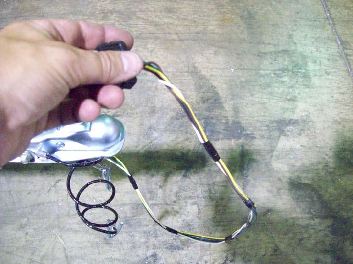
17 Go back and tighten all of the spring mounting nuts that were left loose previously. On the rear shackle, do not over tighten as this will not allow the suspension to move properly. Wiring 17


18 Locate harness and ring terminal. Take the white ground wire and strip it and install ring terminal. 18


19 Locate the ¾ long Philips screw. Install Philips screw through the ground wire into the pre-drilled hole located under the tongue just behind the coupler. 19


20 Extend a tape measure inside the tongue from the rear of the trailer until it protrudes at the front of the trailer under the coupler. Attach both wires of the harness to the end of the tape measure with either tape or a tie. Retract the tape measure until it comes out the back of the tongue with both wires attached. 20


21 Tail light brackets, tail lights Locate the tail light brackets. Locate the tail lights, carriage bolts, nuts and license plate bracket. 21


22 Install the tail light brackets from the rear of the tongue as shown. Position the tail light brackets 8 from the rear of the tongue. 22
 of the")

23 The light with the yellow wires is for the left (driver s side) of the trailer. Slide the carriage bolts into the slots in the back of the tail lights. 23


24 Repeat the process for the right side as shown. Install the left tail light with the license plate holder between the light and the bracket. Repeat for the other side. Then make sure to tighten nuts but don t over tighten them. 24


25 Locate the black tab at the bottom of the tail light. Move the tab toward the rear of the trailer and pull down releasing the bulb assembly from the light housing. 25


26 Loosen the wire retaining screws and install the color matching wires from the wire harness onto the corresponding retaining screws. Re-install the bulb assembly into the light housing making sure to route the wires through the slot in the base of the bulb assembly. 26


27 Install adhesive backed clamps in the locations shown and route the wires through them. Running lights, bracket and skid. Locate the two amber running lights, four small Philips screws, adhesive backed clamps, two ring terminals, and two blue connectors. 27


28 Cut approximately 8 ½ off of the white wires on both running lights. Strip 1/4 of insulation from the wire. 28


29 Install the ring terminals by crimping the terminal onto the bare wire. Locate the skid and light bracket. 29


30 Take one T-bolt off the skid and slide it in the bottom of the tongue. Then install the bracket for the lights and position as shown. Align the ring terminals with the screw hole nearest the wire on the back of the running light. Make sure the wire is routed through the gap on the back of the light so it does not become pinched when the light is installed. 30


31 Install the running lights into the pre-drilled holes in the running light bracket using a Philips screwdriver. Be sure the screw is through the ring terminal on the back side of the lights. This will supply a ground to the lights. DO NOT OVER TIGHTEN Cut 6 off of the brown wire on the left (driver s side) running light. Do not strip the wire. 31


32 Insert brown wire that has been cut into the hole in the connector closest to the hinge. This hole does not pass all the way through. The wire should go in about ½. Pass the other wire through the remaining open slot in the connector at a point close to the running lights. Use pliers to push the metal spade down until it is flush with the plastic. This is what makes the electrical connection between the two wires. Close the plastic cover of the connector over the spade until it snaps into position. 32


33 Cut the exposed strands of wire off of the end of the brown wire on the right (passenger side) running light. Measure 34 back from the front plug on the green/brown wire and pass the brown wire through the open slot in the second light blue connector at this location. The green wire will rest just outside the connector. Insert the brown wire from the running lights into the closed side of the connector and close the spade and cover as previously described. This will make the connection from the main harness to both running lights. 33


34 Locate the adhesive backed clamps. Install them as shown and run brown wire from the running lights through them. Install the skid on the front tongue section now. Tighten the nuts for the skid in the location as shown. 34

35 Tape wiring as shown. 35
 1 1/8 T-bolts from the hardware bag and install them")

36 Fender Installation Locate fenders, washers, T-bolts, and nuts. Locate (2) 1 1/8 T-bolts from the hardware bag and install them into the side rails. Slide them into position over the tire and install two rubber washers and two steel washers as shown. 36


37 Install the fender, two more steel washers, and nuts, center the fender over the axle and tighten the nuts. Repeat for the other side. Locate 8 lug nuts, and wheels. 37


38 Install the wheels with the valve stems facing out. Install the lug nuts with the tapered side facing the wheel. Web strap clip installation Locate 2 web strap clips 38


39 Install a web strap clip on each side rail at the back as shown. Then tighten nuts. Padded cradle installation Locate padded cradles, brackets, and hardware. 39


40 Locate the 4 angle brackets and repair T-bolts. Install the repair T-bolt on the short end of the angle as shown. Install two of the angle brackets on the front cross member and two on the rear as shown. 40


41 Then slide T-bolt over on cross member and align them with the angle brackets. T-bolt 1 bolt Install cradle bracket onto T-bolts on the front and rear cross members. Then install a 1 bolt through the angle bracket at the bottom. Position brackets and then tighten nuts. 41


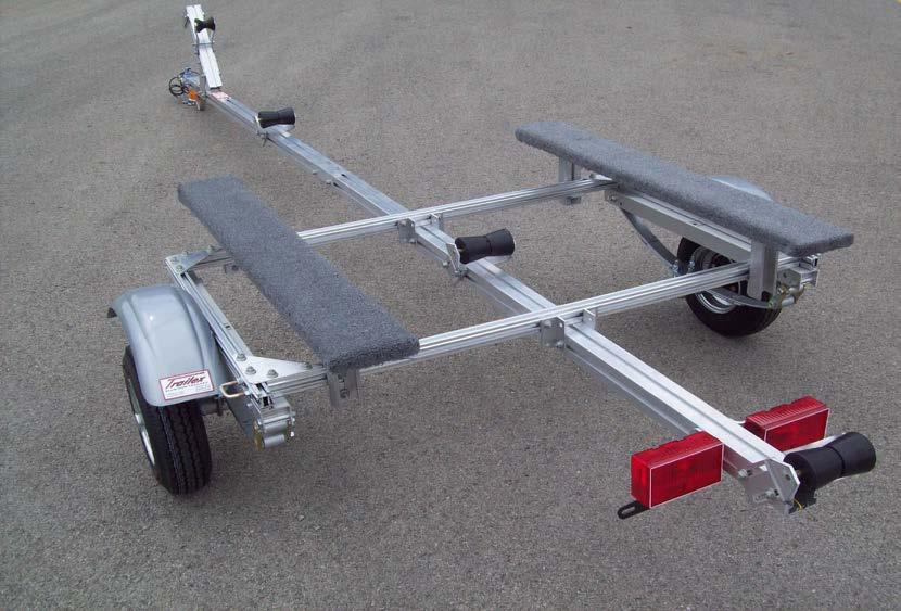
42 Take the nuts and lock washers off the bottom of the padded cradle and position it on top of the angle brackets. Install the lock washers, and nuts then tighten. The padded cradle holder will have to be adjusted for the boat after the trailer is finished. 42


43 Locate the three rollers Install the two front rollers aligned with the T-bolts on the tongue. With the roller bracket tilted, gradually pull it over to the other side and position it. Install nuts and tighten. 43


44 Slide the last roller bracket on over T-bolts and adjust. Install nuts and tighten. Winch post installation Locate winch post, and diagonal braces. 44


45 Install braces on the T-bolt at the front of the tongue section. Position braces and tighten nuts. Install winch post by sliding it through the T-bolts on the braces. 45


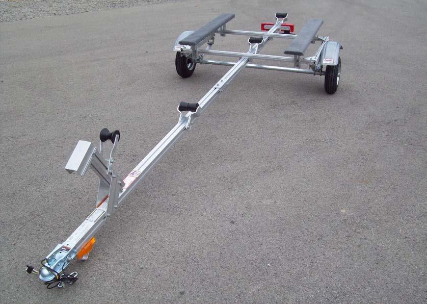
46 Adjust the winch post and tighten nuts. Torque lug nuts Tighten to 80 foot pounds in a crossing pattern. Re-tighten after 25 miles. 46


47 Finished trailer KJM8/09 R 8/12/11 47
48 48
SUT-250-S (These instructions are used for SUT-250-SCLC also)
") SUT-250-S (These instructions are used for SUT-250-SCLC also) Torque wrench, carpenters square, wire cutters, Phillips screwdriver, 7/16, 9/16, and 3/4 combination wrenches, ratchet, 9/16, 3/4, 13/16,
SUT-250-S (These instructions are used for SUT-250-SCLC also) Torque wrench, carpenters square, wire cutters, Phillips screwdriver, 7/16, 9/16, and 3/4 combination wrenches, ratchet, 9/16, 3/4, 13/16,
UNPACK AND IDENTIFY THE FOLLOWING PARTS.
 SUT-250-M2 ASSEMBLY REQUIREMENTS *Torque all T-bolt nuts to 35-40 foot pounds. *Check all lights before towing. *Tire pressure not to exceed recommendation on serial tag. *Re-torque wheel nuts after first
UNPACK AND IDENTIFY THE FOLLOWING PARTS.
 SUT-350-AIT ASSEMBLY REQUIREMENTS *Torque all T-bolt nuts to 35-40 foot pounds. *Check all lights before towing. *Tire pressure not to exceed recommendation on serial tag. *Re-torque wheel nuts after first
SUT-450-I ASSEMBLY REQUIREMENTS
 SUT-450-I Torque wrench, carpenters square, wire cutters, Phillips screwdriver, 7/16, 9/16, and 3/4 combination wrenches, ratchet, 9/16,3/4,13/16, and 7/8 sockets. ASSEMBLY REQUIREMENTS *Torque all T-bolt
UT ASSEMBLY REQUIREMENTS. *Torque all T-bolt nuts to foot pounds.
 UT-1000-8-04 ASSEMBLY REQUIREMENTS *Torque all T-bolt nuts to 35-40 foot pounds. *Check all lights before towing. *Tire pressure not to exceed recommendation on serial tag. *Re-torque wheel nuts after
UT ASSEMBLY REQUIREMENTS. *Torque all T-bolt nuts to foot pounds.
 UT-1200-16-04 ASSEMBLY REQUIREMENTS *Torque all T-bolt nuts to 35-40 foot pounds. *Check all lights before towing. *Tire pressure not to exceed recommendation on serial tag. *Re-torque wheel nuts after
<THESE INSTRUCTIONS MUST BE GIVEN TO THE END USER> B&W
 B&W Trailer Hitches 1216 Hawaii Rd / PO Box 186 Humboldt, KS 66748 P:620.473.3664 F:620.869.9031 Turnoverball Gooseneck Hitch Installation Instructions
SAFETY. Read and understand all safety precautions and instructions before installing this product.
 SAFETY Your safety and the safety of others is very important. In order to help you make informed decisions about safety, we have provided installation instructions and other information. These instructions
GL1800 TRAILER HITCH - INSTALLATION INSTRUCTIONS #GL
 GL1800 TRAILER HITCH - INSTALLATION INSTRUCTIONS #GL18007-20 Read through these instructions completely before attempting installation, lay out all pieces including the numbered hardware bags to familiarize
PDF created with pdffactory trial version
 J 4628 MH 0-5-08 H 458 MH 05-2-08 DWG. REV. ECR/NDR NUMBER REVISED BY DATE 0-02 REPLACED 0-02205 (" TIRES); 0-02 REPLACED 0-02252 (4" TIRES); 00-0900 REPLACED 00-00999 0-069 WAS 0-0228.X 0.00.XXXX 0.00-2-06
<THESE INSTRUCTIONS MUST BE GIVEN TO THE END USER> B&W
 B&W Trailer Hitches 6 Hawaii Rd / PO Box 86 Humboldt, KS 66748 P:60.473664 F:60.869.903 Turnoverball Gooseneck Hitch Installation Instructions MODEL 08
NORTHSTAR TRAILERS. Assembly Guide for SPORTSTAR II Trailer
 NORTHSTAR TRAILERS Assembly Guide for SPORTSTAR II Trailer Congratulations! You are the proud owner of a NORTHSTAR trailer. Please follow the instructions and steps in this manual for proper assembly.
KARAVAN T R A I L E R S
 G F DWG. REV. 5505 5036 KMH 04-28-0 ECR/NDR NUMBER PROPERTY OF TRAILERS, INC. ANY THE WRITTEN PERMISSION OF TRAILERS, DAD.X 0.00.XXXX 0.00 06-8-2 ADDED (4)2-0036. 4/0/2007 REPLACED 208-0003 WITH 208-00049;
GROSS LOAD CAPACITY WHEN USED AS A WEIGHT CARRYING HITCH: 2,000 LBS. TRAILER WEIGHT & 200 LBS. TONGUE WEIGHT.
 PAGE 1 0F 6 GROSS LOAD CAPACITY WHEN USED AS A WEIGHT CARRYING HITCH: 2,000 LBS. TRAILER WEIGHT & 200 LBS. TONGUE WEIGHT. WARNING: ALL NON-TRAILER LOADS APPLIED TO THIS PRODUCT MUST BE SUPPORTED BY 18050
INSTALLATION INSTRUCTIONS
 INSTALLATION INSTRUCTIONS Models: 7105 & 7105TK Dodge Ram 1500 ('02 Current) Ram 2500 & 3500 '03 - Current with stock manual mirrors. IF YOU DO NOT CURRENTLY HAVE MANUAL MIRRORS, THE WRONG SET HAS BEEN
PLEASE READ THIS INSTRUCTIONS CAREFULLY, BEFORE YOU START INSTALLATION
 INSTALLATION INSTRUCTIONS PART NUMBER: L0SXC000 DESCRIPTION: 09 ASCENT TRAILER HITCH PLEASE READ THIS INSTRUCTIONS CAREFULLY, BEFORE YOU START INSTALLATION SAFETY PRECAUTION: When installing Trailer Hitch,
NORTHSTAR TRAILERS. Assembly Guide for SPORTSTAR I Trailer
 NORTHSTAR TRAILERS Assembly Guide for SPORTSTAR I Trailer Congratulations! You are the proud owner of a NORTHSTAR trailer. Please follow the instructions and steps in this manual for proper assembly. We
ST - HD - HDXL Model
 ST - HD - HDXL Model TOOLS REQUIRED FOR ASSEMBLY OF THE TANDEM TOW DOLLY Ratchet Socket Wrench with sockets sizes: 7/16, 9/16, 3/ 4 & 15/16 7/16 Box or Open End Wrench 9/16 Box or Open End Wrench 3/4 Box
<THESE INSTRUCTIONS MUST BE GIVEN TO THE END USER> B&W Trailer Hitches 1216 Hawaii Rd / PO Box 186 Humboldt, KS P: F:
 B&W Trailer Hitches 6 Hawaii Rd / PO Box 86 Humboldt, KS 6678 P:60.7366 F:60.73766 Turnoverball Gooseneck Hitch Installation Instructions MODEL 38 0 06
1. Front Fascia Removal 1.1 Remove the 6 plastic clips that secure the upper valance, then remove. 1.2 Remove 6 upper bolts that hold the grille and f
 STRUT 2015 GMC Denali Collection Installation Manual " 1. Front Fascia Removal 1.1 Remove the 6 plastic clips that secure the upper valance, then remove. 1.2 Remove 6 upper bolts that hold the grille and
SPORTSTER SADDLEBAG KIT. i i02212
 General These saddlebags are designed to fit 99 and later Sportster Model Motorcycles, except XL00 Sport models with gas reservoir shock absorbers and 88R models. See the Service Parts pages for a list
<THESE INSTRUCTIONS MUST BE GIVEN TO THE END USER> B&W
 B&W Trailer Hitches 1216 Hawaii Rd / PO Box 186 Humboldt, KS 66748 Turnoverball Gooseneck Hitch Installation Instructions MODEL 1314 2013 2014 RAM 3500
<THESE INSTRUCTIONS MUST BE GIVEN TO THE END USER> B&W
 B&W Trailer Hitches 6 Hawaii Rd / PO Box 86 Humboldt, KS 6678 P:60.7366 F:60.86.03 Turnoverball Gooseneck Hitch Installation Instructions MODEL 38 0 08
NORTHSTAR TRAILERS. Assembly Guide for MULTISTAR Trailer
 NORTHSTAR TRAILERS Assembly Guide for MULTISTAR Trailer Congratulations! You are the proud owner of a NORTHSTAR trailer. Please follow the instructions and steps in this manual for proper assembly. TRAILER
LGT-311L Bumper LED Light Kit EZ-Go RXV Installation Instructions
 LGT-311L Bumper LED Light Kit EZ-Go RXV Installation Instructions Caution: Please read through the instructions carefully. Before starting this project, remove the system s positive and negative connections
KARAVAN T R A I L E R S
 C 0 MJH B 036 KMH 06--2 04-0-0 ADDED (4)2-0036. REPLACED 8-0003 WITH 8-00049; -0002 WITH -00 - (2X); -00046 WITH -00330; -0004 WITH -0006; -00048 WITH -0006.X 0.00.XXXX 0.00 OF NOTES:.) WINCH SHOULD BE
GrilleGuy.com, LLC. Installation Instructions and Care Guide : Toyota Tacoma Grille UPPER GRILLE
 Installation Instructions and Care Guide : 2001 2004 Toyota Tacoma Grille Thanks again for purchasing your custom grille insert from GrilleGuy.com. The following are some general guidelines that will simplify
POLY TIP-DOWN WINDSHIELD KIT
 POLY TIP-DOWN WINDSHIELD KIT P/N 2881919 APPLICATION Verify accessory fitment at Polaris.com. BEFORE YOU BEGIN Read these instructions and check to be sure all parts and tools are accounted for. Please
<THESE INSTRUCTIONS MUST BE GIVEN TO THE END USER> B&W
 B&W Trailer Hitches 1216 Hawaii Rd / PO Box 186 Humboldt, KS 66748 P:620.473664 F:620.869.9031 Turnoverball Gooseneck Hitch Installation Instructions
MODEL 2604 WARNING <THESE INSTRUCTIONS MUST BE GIVEN TO THE END USER> Custom 5th Wheel Hitch Mounting Rail Installation Instructions
 B&W Trailer Hitches 1216 Hawaii Rd / PO Box 186 Humboldt, KS 66748 P:620.473.3664 F:620.869.9031 Custom 5th Wheel Hitch Mounting Rail Installation Instructions
LittleGiant Trailer Harley Hauler Kit
 3380 N. El Paso St., Colorado Springs, CO 80907 LittleGiant Trailer Harley Hauler Kit User Assembly Manual Visit our website at www.letsgoaero.com For Assistance, please call 1-877-464-2376 or 719-630-3800
SAFETY THIS PRODUCT IS FOR OFFROAD USE ONLY. ALL LIABILITY FOR INSTALLATION AND USE RESTS WITH THE OWNER.
 SAFETY Your safety and the safety of others is very important. In order to help you make informed decisions about safety, we have provided installation instructions and other information. These instructions
INSTALLATION / OPERATING INSTRUCTIONS Reese Elite Series FIFTH WHEEL SLIDER HITCH
 INSTALLATION / OPERATING INSTRUCTIONS Reese Elite Series FIFTH WHEEL SLIDER HITCH DEALER/INSTALLER: (1) Provide this Manual to end user. (2) Physically demonstrate hitching and unhitching procedures in
INSTALLATION INSTRUCTIONS
 REV 1 05/04/2017 INSTALLATION INSTRUCTIONS PART NO. 24388T PRODUCT DESCRIPTION: FRONT BUMPER REPLACEMENT APPLICATION: TOYOTA TACOMA PRODUCT SAFETY & LEGAL DISCLAIMER IMPORTANT READ ALL INSTRUCTIONS CAREFULLY
FENDER ELIMINATOR. Remove axle nut, slide out axle, and drop rear tire away from the fender. (Picture 1)
") TRIUMPH BOBBER Remove axle nut, slide out axle, and drop rear tire away from the fender. (Picture ) Remove () tail light bolts. (Picture ) Unplug stock connectors and remove from underneath the fender.
TRIUMPH BOBBER Remove axle nut, slide out axle, and drop rear tire away from the fender. (Picture ) Remove () tail light bolts. (Picture ) Unplug stock connectors and remove from underneath the fender.
SAFETY THIS PRODUCT IS FOR OFFROAD USE ONLY. ALL LIABILITY FOR INSTALLATION AND USE RESTS WITH THE OWNER.
 SAFETY Your safety and the safety of others is very important. In order to help you make informed decisions about safety, we have provided installation instructions and other information. These instructions
INFINITY MULTA SERIES
 ASSEMBLY ASSEMBLY INSTRUCTIONS INSTRUCTIONS ASSEMBLY INSTRUCTIONS INFINITY MULTA SERIES Workstations, WORKSTATIONS, desks, DESKS, and AND tables TABLES with WITH powered POWERED ADJUSTMENT adjustment PARTS
BX8848 Installation Instructions 4 Diode Wiring Kit For Motorhomes With Red Tail Lights
 For Motorhomes With Red Tail Lights WARNG: Incorrect wiring may result in blown fuses, damaged wiring, fire, or bodily injury. Blue Ox recommends installation of this kit by a trained professional. Blue
INSTALLATION INSTRUCTIONS
 INSTALLATION INSTRUCTIONS [1] Description: Tow Hitch Wire Harness Kit [2] Application: Nissan Rogue Note: Tow Harness application is limited to specific vehicle option packages that include tow harness
Model ET 5000W Operation and Service Manual
 Model ET 5000W Operation and Service Manual Patented 5/16 BALL Load Capacity: 5000 lbs The ET 5000W ESCALATE TRAILER offers ground level roll-on loading and roll-off unloading of equipment with non-tilting
SAFETY SENSORS FIELD OF VIEW WILL BE ALTERED WITH USE OF THE REPLACEMENT BUMPER. Injury hazard
 SAFETY Your safety and the safety of others is very important. In order to help you make informed decisions about safety, we have provided installation instructions and other information. These instructions
SAFETY THIS PRODUCT IS FOR OFFROAD USE ONLY. ALL LIABILITY FOR INSTALLATION AND USE RESTS WITH THE OWNER.
 Installation Instructions SAFETY Your safety and the safety of others is very important. In order to help you make informed decisions about safety, we have provided installation instructions and other
INSTALLATION INSTRUCTIONS SEMI-HIDDEN WINCH MOUNT Part Number:70005 Application: Ford Super Duty
 INSTALLATION INSTRUCTIONS SEMI-HIDDEN WINCH MOUNT Part Number:70005 Application: Ford Super Duty Your safety, and the safety of others, is very important. To help you make informed decisions about safety,
Trailer Parts. Brake Components. Axle Components. Suspensions. Lights & Electrical. Wheels & Tires. Loading Ramps. Couplers & Safety Chains
 Trailer Parts Brake Components Axle Components Suspensions Lights & Electrical Wheels & Tires Loading Ramps Couplers & Safety Chains Trailer Jacks Fenders Dump Trailer Parts Tilt SST Parts Decal Kits Brake
and Original Series Pickup Lift Mounting Instructions Fullsize Chevy & GMC Trucks: 1500 & 2500 LD HD & 3500HD BOLT-ON GUSSET
 r ve and Original Series Pickup Lift Mounting Instructions Fullsize Chevy & GMC Trucks: 1500 & 2500 LD 1999-2007 2500HD & 3500HD 2000-2007 Preparing the Gate 1. Remove the mounting hardware which is banded
VIEW A KARAVAN T R A I L E R S A MJH A FINISH: DWG. #: KRUS-3100-DB10-74-ST SEE B.O.M. N/A N/A
 VIEW A A A 55 MJH 04-24-.XX 0.00.XXXX 0.00 OF 00-00994-A 22 2 5 5 8 7 8 8 5 7 25 8 8 9 2 9 0 28 2 0 20 ITEM NO. NOTES PART NUMBER QTY. 00-0289 MUD FLAP BRACKET 2 2 20-00095 BRAKE LINE 20-00049 FENDER 2
650 Series Cargo Van Lift Mounting Instructions Ford Transit (Standard Roof) 2015-Present
 2015-Present") TOMMY GATE OWNER'S / OPERATOR'S MANUAL 650 Series 650 LB Capacity 650 Series Cargo Van Lift Mounting Instructions Ford Transit (Standard Roof) 2015-Present Installing the Base Plate 1. Examine the interior
TOMMY GATE OWNER'S / OPERATOR'S MANUAL 650 Series 650 LB Capacity 650 Series Cargo Van Lift Mounting Instructions Ford Transit (Standard Roof) 2015-Present Installing the Base Plate 1. Examine the interior
2017 Current Ford Raptor Bump Stop Kit Installation Instructions
 2017 Current Ford Raptor Bump Stop Kit Installation Instructions PREPARATION 1. Disconnect the negative terminal on the battery. Park the vehicle on level ground and set the emergency brake. 2. We recommend
INSTALLATION INSTRUCTIONS DODGE DAKOTA 2 KIT # 682 (2WD), 692 (4WD) 3 KIT # 683 (2WD), 693 (4WD)
, 692 (4WD) 3 KIT # 683 (2WD), 693 (4WD)") INSTALLATION INSTRUCTIONS 1997-1999 DODGE DAKOTA 2 KIT # 682 (2WD), 692 (4WD) 3 KIT # 683 (2WD), 693 (4WD) Installation of a Performance Accessories body lift kit will change the vehicle s center of gravity
INSTALLATION INSTRUCTIONS 1997-1999 DODGE DAKOTA 2 KIT # 682 (2WD), 692 (4WD) 3 KIT # 683 (2WD), 693 (4WD) Installation of a Performance Accessories body lift kit will change the vehicle s center of gravity
1 M-3000-H4 F150 4X4 Lowering Kit
 READ INSTRUCTIONS COMPLETELY THROUGH BEFORE STARTING. IT IS RECOMMENDED THAT INSTALLATION BE DONE BY A QUALIFIED MECHANIC. REPLACE ALL STOCK PARTS THAT ARE DAMAGED OR WORN. ALWAYS WEAR EYE PROTECTION.
and Original Series Pickup Lift Mounting Instructions Fleetside Chevy & GMC Trucks Fleetside 4-door Chevy & GMC Trucks T-100
 r ve and Original Series Pickup Lift Mounting Instructions Fleetside Chevy & GMC Trucks - 1960-1987 Fleetside 4-door Chevy & GMC Trucks - 1988-1991 Preparing the Gate 1. Remove the mounting hardware which
TOYOTA VENZA 2009 TRAILER WIRE HARNESS Procedure
 Part Number: PT791-0T099 Kit Contents Item # Quantity Reqd. Description 1 1 Trailer Wire Harness Module 2 1 4-Flat Harness 3 1 Battery Power Wire Harness 4 1 Mounting Bracket, 4-Flat 5 2 Screw #10-24 6
INSTALLATION INSTRUCTIONS
 INSTALLATION INSTRUCTIONS Model: 8510 & 8510TK Ford E Series Van 1994 2002 with stock power mirrors Tools required for the installation are: 7/16 socket, T20 screwdriver or 8mm socket, screwdriver, phillips
Required tools General hand tools 21/64" drill bit Torque wrench Threadlocker Center punch
 Slipper Spring Kit (part numbers 2560, 2570 and 2580) Item Qty Part number Description 1... 8... 350054-50...3/8-16 x 1" grade 8 self-tapping screw 2... 4... 350084-00...7/16-14 x 4" grade 5 3... 6...
INSTALLATION INSTRUCTIONS For 65800, 65801, 66355, 69250, Rear Bumper And Tire Carrier For Jeep XJ Cherokee
 INSTALLATION INSTRUCTIONS For 65800, 65801, 66355, 69250, 69251 Rear Bumper And Tire Carrier For Jeep XJ Cherokee Your safety, and the safety of others, is very important. To help you make informed decisions
2005+ Roll Bar (Mm5RB-20.1 to -20.6) Recommended Center punch 1/8" pilot drill 1-3/4" Hole saw 2" Hole saw
 Recommended Center punch 1/8 pilot drill 1-3/4 Hole saw 2 Hole saw") 3430 Sacramento Dr., Unit D San Luis Obispo, CA 93401 Telephone: 805/544-8748 Fax: 805/544-8645 www.maximummotorsports.com 2005+ Roll Bar (Mm5RB-20.1 to -20.6) Recommended Center punch 1/8" pilot drill
3430 Sacramento Dr., Unit D San Luis Obispo, CA 93401 Telephone: 805/544-8748 Fax: 805/544-8645 www.maximummotorsports.com 2005+ Roll Bar (Mm5RB-20.1 to -20.6) Recommended Center punch 1/8" pilot drill
INSTALLATION INSTRUCTIONS
 INSTALLATION INSTRUCTIONS Honda Dealer: Please give a copy of these instructions to your customer. PARTS LIST (15) (8) (12) (14) (13) (10) (11) (18) (17) (1) Accessory Application Publications No. TRX500FA/FGA
Assembly Instructions
 Assembly Instructions Part Number Description Model Approx. Assembly Time 99994-0903 Windshield Wiper Kit Mule SX 1 Hour WARNING Improper installation of this accessory could result in an accident causing
OIL COOLER KIT CHEVY CAMARO 2.0T PARTS LIST AND INSTALLATION GUIDE INSTALL DIFFICULTY DISCLAIMER CAUTION TOOLS NEEDED NOTE INSTALL PROCEDURE
 PARTS LIST AND PARTS INCLUDED 3PC APPLICATION-SPECIFIC MOUNTING BRACKETS 1PC HORN RELOCATION MOUNTING BRACKET 1PC 25-ROW OIL COOLER (SLEEK SILVER OR STEALTH BLACK) 1PC 4'4" STAINLESS STEEL BRAIDED HOSE
INSTALLATION INSTRUCTIONS
 PART NO. 23100T PRODUCT DESCRIPTION: Front Winch Bumper, Center Section PRODUCT SAFETY & LEGAL DISCLAIMER IMPORTANT READ ALL INSTRUCTIONS CAREFULLY BEFORE INSTALLING, FAILURE TO DO SO MAY CAUSE PERSONAL
and Original Series Pickup Lift Mounting Instructions T-150-T T-150 PART#5177 T-150-T
 Fullsize Chevy & GMC Trucks- 988-999 Toyota Tundra- 2000-2006 Toyota T-00-993-999 Preparing the Gate r ve and Original Series Pickup Lift Mounting Instructions. Remove the mounting hardware which is banded
SAFETY THIS PRODUCT IS FOR OFFROAD USE ONLY. ALL LIABILITY FOR INSTALLATION AND USE RESTS WITH THE OWNER.
 SAFETY Your safety and the safety of others is very important. In order to help you make informed decisions about safety, we have provided installation instructions and other information. These instructions
<THESE INSTRUCTIONS MUST BE GIVEN TO THE END USER> 1 2 " X 1 1 2" Hex Cap Screws " Split Lock Washers " Threaded block 4
 B&W Trailer Hitches 1216 Hawaii Rd / PO Box 186 Humboldt, KS 66748 P:620.473.3664 F:620.473.3766 Companion Hitch Installation Instructions 20,000 LBS.
LPE C5 Battery Relocation Kit
 LPE C5 Battery Relocation Kit The LPE C5 Corvette battery relocation kit improves vehicle weight distribution by moving weight to the rear of the vehicle. The improved weight distribution increases traction
Trailer Parts. Brake Components. Axle Components. Suspensions. Lights & Electrical. Wheels & Tires. Loading Ramps. Couplers & Safety Chains
 Trailer Parts Brake Components Axle Components Suspensions Lights & Electrical Wheels & Tires Loading Ramps Couplers & Safety Chains Trailer Jacks Fenders Dump Trailer Parts Tilt SST Parts Decal Kits Brake
SAFETY THIS PRODUCT IS FOR OFFROAD USE ONLY. ALL LIABILITY FOR INSTALLATION AND USE RESTS WITH THE OWNER.
 SAFETY Your safety and the safety of others is very important. In order to help you make informed decisions about safety, we have provided installation instructions and other information. These instructions
Assembly Instructions
 Assembly Instructions SP-7000 Serial No. 140410300001SP-7000 and higher Madison Heights, Michigan 48071 800-SALTERS www.snowexproducts.com CUSTOMER COPY TrynEx International 2014 F51558 REV-A140905 1 Introduction
** DO NOT EXCEED THE RECOMMENDED VEHICLE TOWING WEIGHT RATING ** DODGE RAM 1500
 10/3/2017 DODGE RAM 1500 WARNING!! BRAKE, FUEL, AND ELECTRICAL LINES MAY NEED TO BE LOOSENED OR REPOSITIONED TO PROVIDE CLEARANCE FOR NEW HARDWARE. ON SHORT BED MODELS, CHECK FOR ADEQUATE TURNING CLEARANCE
and Original Series Pickup Lift Mounting Instructions Fullsize Nissan Titan Trucks present T-420 BOLT-ON GUSSET PART#5257
 and Original Series Pickup Lift Mounting Instructions Fullsize Nissan Titan Trucks- 2004-present Preparing the Gate 1. Remove the mounting hardware which is banded to the liftgate. 2. Verify mounting bracket
Type 2 Push-Through 37 Ton Log Splitter. Assembly Manual
 Type 2 Push-Through 37 Ton Log Splitter Assembly Manual Refer to this manual for the following models: RS37PT-LF09PC-16-1 RS37PT-LF09EC-16-1 RS37PT-LF09EC-16-2 RS37PT-LF13EC-22-1 RS37PT-LF13EC-22-2 RS37PT-LF15EC-22-1
<THESE INSTRUCTIONS MUST BE GIVEN TO THE END USER> BASE BOLT BAG (RVB3500) ITEM DESCRIPTION QTY. 1 2 " X 1 1 2" Hex Cap Screws 16
 ITEM DESCRIPTION QTY. 1 2 X 1 1 2 Hex Cap Screws 16") B&W Trailer Hitches 1216 Hawaii Rd / PO Box 186 Humboldt, KS 66748 P:620.473.3664 F:620.869.9031 Companion Hitch Installation Instructions 20,000 LBS.
B&W Trailer Hitches 1216 Hawaii Rd / PO Box 186 Humboldt, KS 66748 P:620.473.3664 F:620.869.9031 Companion Hitch Installation Instructions 20,000 LBS.
INSTALLATION & OWNER S MANUAL
 Rev. A, p. 1 of 13 INSTALLATION & OWNER S MANUAL Polaris Ranger (2009-) Straight UTV Steel Plow with Vehicle Mount Kit 6 Wide Snow Plow (p/n: 1POLSP) (fits the 500 H.O., 700 & 800 HD & XP) The contents
INSTALLATION INSTRUCTIONS HD BUMPER AND WINCH MOUNTING KIT Part Number: 74777, Application: 08-NEWER FORD SUPER DUTY WARNING
 INSTALLATION INSTRUCTIONS HD BUMPER AND WINCH MOUNTING KIT Part Number: 74777, 76250 Application: 08-NEWER FORD SUPER DUTY Your safety, and the safety of others, is very important. To help you make informed
TOYOTA TUNDRA 2 & 4WD 3 BODY LIFT KIT INSTALLATION INSTRUCTIONS 2006 KIT# 5623
 3651 N Highway 89 Chino Valley, AZ 86323 (928) 636-7080 www.p-a-g.net TOYOTA TUNDRA 2 & 4WD 3 BODY LIFT KIT INSTALLATION INSTRUCTIONS 2006 KIT# 5623 Installation of a Performance Automotive Group body
SAFETY. Injury hazard
 SAFETY Your safety and the safety of others is very important. In order to help you make informed decisions about safety, we have provided installation instructions and other information. These instructions
LGT-312L E-Z-Go TXT Light Bar Bumper Kit Installation Instructions
 LGT-312L E-Z-Go TXT 2014+ Light Bar Bumper Kit Installation Instructions Caution: Please read through the instructions carefully. Before starting this project, remove the system s positive and negative
»Product» Safety Warning
 C1351 Installation Instructions 2014 Chevy/GMC, ½ Ton, 2/4wd 3.5" Combo Kit Read and understand all instructions and warnings prior to installation of product and operation of vehicle. Zone Offroad Products
INSTALLATION INSTRUCTIONS
 INSTALLATION INSTRUCTIONS OUTLAW REAR BUMPER APPLICATION: 2016-2018 Chevrolet Silverado 1500 PART NUMBER: 58-81005 CONTENT ITEM QUANTITY DESCRIPTION TOOLS NEEDED 1 1 REAR BUMPER 18MM WRENCH 2 4 SENSOR
LIFT-304 (3 ) and LIFT-104 (6 ) Drop Spindle Lift Kits Yamaha G22, Gas or Electric Installation Instructions
 and LIFT-104 (6 ) Drop Spindle Lift Kits Yamaha G22, Gas or Electric Installation Instructions") LIFT-304 (3 ) and LIFT-104 (6 ) Drop Spindle Lift Kits Yamaha G22, Gas or Electric Installation Instructions LIFT-304 LIFT-104 Contents of LIFT-304/104 Yamaha G22 Lift Kit: a (1 ea.) Passenger Side Spindle
LIFT-304 (3 ) and LIFT-104 (6 ) Drop Spindle Lift Kits Yamaha G22, Gas or Electric Installation Instructions LIFT-304 LIFT-104 Contents of LIFT-304/104 Yamaha G22 Lift Kit: a (1 ea.) Passenger Side Spindle
Installation instructions, accessories. Body kit
 Installation instructions, accessories Instruction No 31265373 Version 1.1 5 Part. No. Body kit IMG-256263 Volvo Car Corporation Body kit - 31265373 - V1.1 Page 1 / 42 Equipment A0000162 A0000163 IMG-239664
G-170. r ve Pickup Lift Mounting Instructions Fullsize Chevy & GMC Trucks- 1500, 2500 & 3500: 2007-present
 Fullsize Chevy & GMC Trucks- 1500, 2500 & 3500: 2007-present Preparing the Gate 1. Remove the mounting hardware which is banded to the liftgate. 2. Verify mounting bracket kit (Figure 1 and Table 1). 18-5/8"
TOYOTA VENZA 2009 TRAILER WIRE HARNESS Procedure
 Part Number: PT791-0T099 Kit Contents Item # Quantity Reqd. Description 1 1 Trailer Wire Harness Module 2 1 4-Flat Harness 3 1 Battery Power Wire Harness 4 1 Mounting Bracket, 4-Flat 5 2 Screw #10-24 6
LIFT Drop Spindle Lift Kit E-Z-Go RXV Gas or Electric Installation Instructions
 LIFT-107 6 Drop Spindle Lift Kit E-Z-Go RXV Gas or Electric Installation Instructions Contents of LIFT-107 E-Z-Go RXV Drop Spindle Lift Kit: a (1 ea.) Driver Side Spindle b (1 ea.) Passenger Side Spindle
SAFETY THIS PRODUCT IS FOR OFFROAD USE ONLY. ALL LIABILITY FOR INSTALLATION AND USE RESTS WITH THE OWNER.
 SAFETY Your safety and the safety of others is very important. In order to help you make informed decisions about safety, we have provided installation instructions and other information. These instructions
INSTALLATION INSTRUCTIONS
 INSTALLATION INSTRUCTIONS Accessory Application Publications No. S 1998 CIVIC 2/3/4-DOOR All 18767 Issue Date SEP 1997 PARTS LIST Fog Light Kit: P/N 08V31-S01-100 Right fog light (marked R ) Fuse label
Mahindra Pikup (2009 Production Onwards)
") Mahindra Pikup (009 Production Onwards) Steel Bull Bar INSTALLATION INSTRUCTIONS Accessory Part No. BBAR07 Installation Time: 60min Approx Bull Bar Weight: 60KG! Important: Please read each step of these
Mahindra Pikup (009 Production Onwards) Steel Bull Bar INSTALLATION INSTRUCTIONS Accessory Part No. BBAR07 Installation Time: 60min Approx Bull Bar Weight: 60KG! Important: Please read each step of these
INSTALLATION INSTRUCTIONS
 INSTALLATION INSTRUCTIONS WARNING: NEVER EXCEED YOUR VEHICLE MANUFACTURER'S RECOMMENDED TOWING CAPACITY A20 5TH WHEEL HITCH TABLE OF CONTENTS Page# Description 1 Warnings & Precautions 2 - Assembly & Installation
READ AND UNDERSTAND ALL INSTRUCTIONS AND WARNINGS PRIOR TO INSTALLATION OF SYSTEM AND OPERATION OF VEHICLE.
 #9378 Installation Instructions 3 Body Lift Kit 1998-2000 Ranger READ AND UNDERSTAND ALL INSTRUCTIONS AND WARNINGS PRIOR TO INSTALLATION OF SYSTEM AND OPERATION OF VEHICLE. SAFETY WARNING BDS Suspension
INSTALLATION INSTRUCTION 88581
 INSTALLATION INSTRUCTION 88581 FOR RANCHO SUSPENSION SYSTEM RS6581B: DODGE RAM READ ALL INSTRUCTIONS THOROUGHLY FROM START TO FINISH BEFORE BEGINNING INSTALLATION Rev C IMPORTANT NOTES! WARNING: This suspension
VELAR HITCH INSTALLATION INSTRUCTIONS TOW RANGE ROVER MODEL/ TRIM YEARS: WEIGHT CAPACITY to Present PARTS & SUPPLIES: TOOLS REQUIRES:
 HITCH INSTALLATION INSTRUCTIONS MAKE: RANGE ROVER YEARS: 2018 to Present MODEL/ TRIM VELAR PACKAGE: TOW WEIGHT CAPACITY TRAILER TONGUE 5300 LBS. 300 LBS. INSTALLATION TIME: 2 HOURS NO YES YES PARTS & SUPPLIES:
MOUNT BRACKET PARTS and HARDWARE: Installation parts with * come loose in hardware kit bag. Other parts are preassembled
 INSTALL INSTRUCTIONS C-DMM-2006 Dash Monitor Mount 2017-2019 F-250, 350, 450 Pickup, F-450 and 550 Cab Chassis, 2015-2019 Ford F-150 and 2018-2019 Expedition Notes: 1. The C-DMM-2000 series Dash Monitor
Installation Notes: #86000-R Race Series +3.5 L/T Kit
 159 North Maple St. Unit J, CORONA CA 92880 P. 951-737-9682 F. 951-737-9006 WWW.CHAOSFAB.COM Installation Notes: #86000-R Race Series +3.5 L/T Kit Factory manual is recommended for removal and re-installation
650 Series Cargo Van Lift Mounting Instructions Fullsize Ford 1992-Present
 TOMMY GATE OWNER'S / OPERATOR'S MANUAL 650 Series 650 LB Capacity 650 Series Cargo Van Lift Mounting Instructions Fullsize Ford 1992-Present Installing the Base Plate 1. Examine the interior and exterior
FREIGHT TRAIN HEADLAMP NACELLE KITS
 -J09 0-08-8 FREIGHT TRAIN HEADLAMP NACELLE KITS GENERAL Kit Numbers 6000, 600 Models For model fitment information, see the P&A retail catalog or the Parts and Accessories section of wwwharley-davidsoncom
M-9603-FST FOCUS ST COLD AIR INTAKE KIT INSTALLATION INSTRUCTIONS
 M-9603-FST Please visit www.fordracingparts.com for the most current instruction information.!!! PLEASE READ ALL OF THE FOLLOWING INSTRUCTIONS CAREFULLY PRIOR TO INSTALLATION. AT ANY TIME YOU DO NOT UNDERSTAND
INSTALLATION INSTRUCTIONS 97 FORD EXPEDITION
 INSTALLATION INSTRUCTIONS 97 FORD EXPEDITION 1. Read the instructions completely and carefully before you begin. Check the kit for proper contents (refer to the part s list and the picture diagrams). Before
A B C D E F. Tools Required (supplied by others)
") Page 1 of 17 Parts List Below Deck Automatic Retractable Security Cover Kit (1) Tube End Bearing Plate (A) (1) Rope Reel and Cover Drum Motor Assembly (B) (1) Cover Drum (1) Pulley Support Channel (2)
Page 1 of 17 Parts List Below Deck Automatic Retractable Security Cover Kit (1) Tube End Bearing Plate (A) (1) Rope Reel and Cover Drum Motor Assembly (B) (1) Cover Drum (1) Pulley Support Channel (2)
Alpha Series Front Bumper Installation Manual
 1 K Alpha Series Front Bumper Installation Manual - 2017 Ford Super Duty 2 Kelderman Alpha Series Front Bumper Light Winch - Contents - Kit Numbers. (3) - Introduction. (4) - Safety... (5) - Bumper Removal......
INSTALLATION MANUAL
 INSTALLATION MANUAL 2563000 Parts List 1 Carrier weldment 2 Support arm assembly 1 Third brake light assembly 1 Light extension bracket 1 Spare tire adjustment plate 1 Spare tire mount plate 1 Female spade
LIFT-507 BMF Lift Kit E-Z-Go RXV Gas or Electric Installation Instructions
 LIFT-507 BMF Lift Kit E-Z-Go RXV Gas or Electric Installation Instructions Contents of LIFT-507 E-Z-Go RXV BMF Lift Kit: a (1 ea.) BMF A-Arm Assembly b (1 ea.) Driver Side Shock Tower c (1 ea.) Passenger