SUT-250-S (These instructions are used for SUT-250-SCLC also)
|
|
|
- Owen Taylor
- 5 years ago
- Views:
Transcription

1 SUT-250-S (These instructions are used for SUT-250-SCLC also) Torque wrench, carpenters square, wire cutters, Phillips screwdriver, 7/16, 9/16, and 3/4 combination wrenches, ratchet, 9/16, 3/4, 13/16, and 7/8 sockets. ASSEMBLY REQUIREMENTS *Torque all T-bolt nuts to foot pounds. *Check all lights before towing. *Tire pressure not to exceed recommendation on serial tag. *Re-torque wheel nuts after first 25 miles to 80 ft. pounds and periodically thereafter. Failure to follow the assembly instructions could result in serious injury or death. Incorrect assembly or modifications to your trailer will void any specific or implied warranty. For questions or assistance assembling your trailer call


2 UNPACK AND IDENTIFY THE FOLLOWING PARTS. Tongue section and angle bracket for cross members. Side Rails and cross members Axle assembly, springs and U bolt hardware. 2


3 Fenders and tires Rollers winch post and braces. 3


4 Lights, brackets, harness, and hardware Skid and side marker bracket 4


5 Tongue assembly T-bolts Unwrap the two tongue sections and loosen the nuts on the splice plates. Also make sure that the front tongue section has 4 T-bolts on each side before the tongue sections go together. Slide splice plates over the adjacent tongue section until the plates are centered between the tongue sections. 5


6 Tighten nuts. Frame Assembly Rear cross member Side rails Front cross member 6


7 Locate the front cross member and slide it into the front of the side rail. Add the rear cross member to the side rail. Then attach the other side rail to the cross members. 7


8 Square the frame and tighten all the corner brackets. Your frame should look like this. 8


9 Frame Attachment Locate the two angle brackets to install the frame to the tongue. Slide two T-bolts forward from the left side of the rear tongue section to be used to mount the angle brackets to the frame. 9


10 Rear cross member shown Set the frame assembly on top of the tongue with the attaching brackets behind the cross members. Pencil marks Take the angle brackets and install them on the tongue and front and rear cross members. Line up the back edge of the brackets with the pencil marks on the tongue. 10


11 Pencil marks Line up the tongue with the pencil marks on the cross members. Tighten nuts. Your trailer should look like this at this point. 11


12 Spring Installation Remove the bolt, nut and bushings from the front sub rail. Take the two bushing and install them into the eye of the leaf spring as shown. Insert the spring and bushing back into the sub rail. 12


13 Frame is shown up side down Reinstall the nut and bolt into the center hole of the sub rail with the nut towards the inside of the trailer. Do not tighten yet. 13


14 Remove the two bolts from the shackle holder at the rear of the spring and install the shackle holder into the rear spring hanger with the nuts toward the inside of the trailer. These nuts can be tightened at this time. 14


15 Serial plate Locate the axle and install it on the springs as shown. Make sure the locating studs on the springs are in the holes on the axle s spring seat. Face the axle s serial plate toward the rear of the trailer to protect it from debris. Locate the U-bolts and tie plates. 15


16 Install the U-bolts and tie plates as shown. Install the nuts and tighten them evenly. 16


17 Go back and tighten all of the spring mounting nuts that were left loose previously. On the rear shackle, do not over tighten as this will not allow the suspension to move properly. 17


18 Wiring Locate harness and ring terminal. Cut the white ground wire to 24 long. Strip the casing from the wire and install the ring terminal. 18


19 Locate the ¾ long Philips screw. Install Philips screw through the ground wire into the pre-drilled hole located under the tongue just behind the coupler. 19


20 Extend a tape measure inside the tongue from the rear of the trailer until it protrudes at the front of the trailer under the coupler. Attach both wires of the harness to the end of the tape measure with either tape or a tie. Retract the tape measure until it comes out the back of the tongue with both wires attached. 20


21 Tail light brackets, tail lights Locate the tail light brackets. Locate the tail lights, carriage bolts, nuts and license plate bracket. 21


22 Slide one T-bolt from each side of the rear tongue section towards the front of the trailer. Install tail light brackets and position them 8 from the rear of the tongue. Once tail light brackets are in position tighten nuts. 22
 of the")

23 The light with the yellow wires is for the left (driver s side) of the trailer. Slide the carriage bolts into the slots in the back of the tail lights. 23


24 Repeat the process for the right side as shown. Install the left tail light with the license plate holder between the light and the bracket. Repeat for the other side. Tighten nuts but don t over tighten them. 24


25 Shown up side down Locate the black tab on the underside of the tail light. Move the tab toward the rear of the trailer and pull up releasing the bulb assembly from the light housing. 25


26 Loosen the wire retaining screws and install the color matching wires from the wire harness onto the corresponding retaining screws. Re-install the bulb assembly into the light housing making sure to route the wires through the slot in the base of the bulb assembly. 26


27 Install adhesive backed clamps in the locations shown and route the wires through them. Running lights, bracket and skid. Locate the two amber running lights, four small Philips screws, adhesive backed clamps, two ring terminals, and two blue connectors. 27


28 Cut approximately 8 ½ off of the white wires on both running lights. Strip 1/4 of insulation from the wire. 28


29 Install the ring terminals by crimping the terminal onto the bare wire. Locate the skid and light bracket. 29


30 Take one T-bolt off the skid and slide it in the bottom of the tongue. Set the skid aside for now. Install the bracket for the lights and position as shown. Align the ring terminals with the screw hole nearest the wire on the back of the running light. Make sure the wire is routed through the gap on the back of the light so it does not become pinched when the light is installed. 30


31 Install the running lights into the pre-drilled holes in the running light bracket using a Philips screwdriver. Be sure the screw is through the ring terminal on the back side of the lights. This will supply a ground to the lights. DO NOT OVER TIGHTEN Cut 6 off of the brown wire on the left (driver s side) running light. Do not strip the wire. 31


32 Harness passes through open hole. Cut wire goes into closed off hole. Insert brown wire that has been cut into the hole in the connector closest to the hinge. This hole does not pass all the way through. The wire should go in about ½. Pass the other wire through the remaining open slot in the connector at a point close to the running lights. Use pliers to push the metal spade down until it is flush with the plastic. This is what makes the electrical connection between the two wires. Close the plastic cover of the connector over the spade until it snaps into position. 32
 running light.")

33 Cut the exposed strands of wire off of the end of the brown wire on the right (passenger side) running light. Cut the brown/green harness so it can be separated to accommodate the connector. Be care full not to cut through the wires. Also cut as close to the front of the tongue section as possible. 33


34 Pass the brown wire from the harness through the open slot in the connector at this location. The green wire will rest just outside the connector. Insert the brown wire from the running lights into the closed side of the connector and close the spade and cover as previously described. This will make the connection from the main harness to both running lights. 34


35 Locate the adhesive backed clamps. Install them as shown and run brown wire from the running lights through them. Install the skid on the front tongue section now. Tighten the nuts for the skid in the location as shown. 35


36 Tape the harness as shown. 36
 1 1/8 T-bolts from the hardware bag and install them")

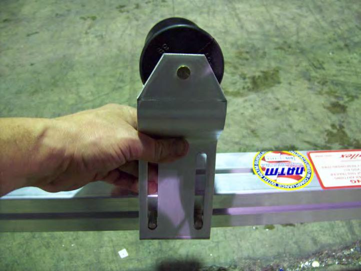
37 Fender Installation Locate fenders, washers, T-bolts, and nuts. Locate (2) 1 1/8 T-bolts from the hardware bag and install them into the side rails. Slide them into position over the tire and install two rubber washers and two steel washers as shown. 37


38 Install the fender, two more steel washers, and nuts, center the fender over the axle and tighten the nuts. Repeat for the other side. Locate 8 lug nuts, and wheels. 38


39 Install the wheels with the valve stems facing out. Install the lug nuts with the tapered side facing the wheel. Web strap clip installation Locate 2 web strap clips 39


40 Install a web strap clip on each side rail at the back as shown. Then tighten nuts. 40


41 Padded cradle installation Locate padded cradles, brackets, and hardware. Repair T-bolt Locate the 4 angle brackets and repair T-bolts. Install the repair T-bolt on the short end of the angle as shown. 41


42 Install two of the angle brackets on the front cross member and two on the rear as shown. Also angle brackets can be installed on the top of the cross member as shown below. Slide T-bolt over on cross member and align them with the angle brackets. 42


43 Cradle bracket shown with 1 bolt and nut. Shown on the bottom 43


44 Shown on the top The angle bracket can be mounted either on the bottom or the top of the cross member depending on the hull of the boat. T-bolt 1 bolt Install cradle bracket onto T-bolts on the front and rear cross members. Then install a 1 bolt through the angle bracket at the bottom. Position brackets and then tighten nuts. 44


45 Your trailer should look like this at this point. Take the nuts and lock washers off the bottom of the padded cradles so they can be installed on the angle brackets. 45


46 Install the padded cradles on the brackets as shown. Next reinstall the lock washers and nuts then tighten. The padded cradle holders will have to be adjusted for the boat after the trailer is finished. 46

47 Locate the two roller assemblies. 47


48 Align the roller bracket with the two rear T-bolts on the front tongue section. With the roller bracket tilted, gradually pull it over to the other side and position it. Install nuts and tighten. Remove the four T-bolts from the rear tongue section and install them into the roller brackets as shown. 48


49 Now install the roller assembly on the rear tongue section as shown. Then position and tighten nuts. Bow Stand Assembly Locate the bow stand. 49


50 Install the bow stand as shown. Final adjustments will be made when boat is on the trailer. Be sure to go back and tighten all the nuts. 50

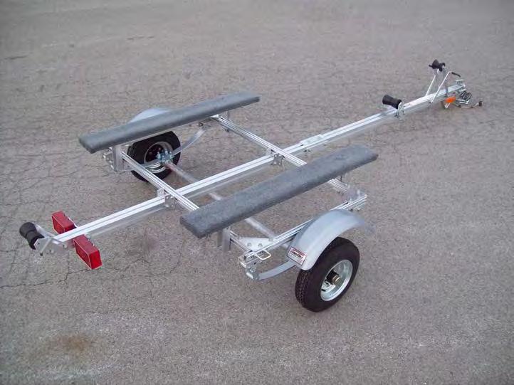
51 Finished trailer 51


52 52 KJM 1/5/11, REVISED 10/31/13, REVISED 1/26/15
UNPACK AND IDENTIFY THE FOLLOWING PARTS.
 SUT-500-S ASSEMBLY REQUIREMENTS *Torque all T-bolt nuts to 35-40 foot pounds. *Check all lights before towing. *Tire pressure not to exceed recommendation on serial tag. *Re-torque wheel nuts after first
UNPACK AND IDENTIFY THE FOLLOWING PARTS.
 SUT-350-AIT ASSEMBLY REQUIREMENTS *Torque all T-bolt nuts to 35-40 foot pounds. *Check all lights before towing. *Tire pressure not to exceed recommendation on serial tag. *Re-torque wheel nuts after first
UNPACK AND IDENTIFY THE FOLLOWING PARTS.
 SUT-250-M2 ASSEMBLY REQUIREMENTS *Torque all T-bolt nuts to 35-40 foot pounds. *Check all lights before towing. *Tire pressure not to exceed recommendation on serial tag. *Re-torque wheel nuts after first
SUT-450-I ASSEMBLY REQUIREMENTS
 SUT-450-I Torque wrench, carpenters square, wire cutters, Phillips screwdriver, 7/16, 9/16, and 3/4 combination wrenches, ratchet, 9/16,3/4,13/16, and 7/8 sockets. ASSEMBLY REQUIREMENTS *Torque all T-bolt
UT ASSEMBLY REQUIREMENTS. *Torque all T-bolt nuts to foot pounds.
 UT-1000-8-04 ASSEMBLY REQUIREMENTS *Torque all T-bolt nuts to 35-40 foot pounds. *Check all lights before towing. *Tire pressure not to exceed recommendation on serial tag. *Re-torque wheel nuts after
UT ASSEMBLY REQUIREMENTS. *Torque all T-bolt nuts to foot pounds.
 UT-1200-16-04 ASSEMBLY REQUIREMENTS *Torque all T-bolt nuts to 35-40 foot pounds. *Check all lights before towing. *Tire pressure not to exceed recommendation on serial tag. *Re-torque wheel nuts after
GROSS LOAD CAPACITY WHEN USED AS A WEIGHT CARRYING HITCH: 2,000 LBS. TRAILER WEIGHT & 200 LBS. TONGUE WEIGHT.
 PAGE 1 0F 6 GROSS LOAD CAPACITY WHEN USED AS A WEIGHT CARRYING HITCH: 2,000 LBS. TRAILER WEIGHT & 200 LBS. TONGUE WEIGHT. WARNING: ALL NON-TRAILER LOADS APPLIED TO THIS PRODUCT MUST BE SUPPORTED BY 18050
<THESE INSTRUCTIONS MUST BE GIVEN TO THE END USER> B&W
 B&W Trailer Hitches 1216 Hawaii Rd / PO Box 186 Humboldt, KS 66748 P:620.473.3664 F:620.869.9031 Turnoverball Gooseneck Hitch Installation Instructions
PLEASE READ THIS INSTRUCTIONS CAREFULLY, BEFORE YOU START INSTALLATION
 INSTALLATION INSTRUCTIONS PART NUMBER: L0SXC000 DESCRIPTION: 09 ASCENT TRAILER HITCH PLEASE READ THIS INSTRUCTIONS CAREFULLY, BEFORE YOU START INSTALLATION SAFETY PRECAUTION: When installing Trailer Hitch,
2017 Current Ford Raptor Bump Stop Kit Installation Instructions
 2017 Current Ford Raptor Bump Stop Kit Installation Instructions PREPARATION 1. Disconnect the negative terminal on the battery. Park the vehicle on level ground and set the emergency brake. 2. We recommend
LittleGiant Trailer Harley Hauler Kit
 3380 N. El Paso St., Colorado Springs, CO 80907 LittleGiant Trailer Harley Hauler Kit User Assembly Manual Visit our website at www.letsgoaero.com For Assistance, please call 1-877-464-2376 or 719-630-3800
PDF created with pdffactory trial version
 J 4628 MH 0-5-08 H 458 MH 05-2-08 DWG. REV. ECR/NDR NUMBER REVISED BY DATE 0-02 REPLACED 0-02205 (" TIRES); 0-02 REPLACED 0-02252 (4" TIRES); 00-0900 REPLACED 00-00999 0-069 WAS 0-0228.X 0.00.XXXX 0.00-2-06
<THESE INSTRUCTIONS MUST BE GIVEN TO THE END USER> B&W
 B&W Trailer Hitches 6 Hawaii Rd / PO Box 86 Humboldt, KS 66748 P:60.473664 F:60.869.903 Turnoverball Gooseneck Hitch Installation Instructions MODEL 08
NORTHSTAR TRAILERS. Assembly Guide for SPORTSTAR II Trailer
 NORTHSTAR TRAILERS Assembly Guide for SPORTSTAR II Trailer Congratulations! You are the proud owner of a NORTHSTAR trailer. Please follow the instructions and steps in this manual for proper assembly.
SAFETY THIS PRODUCT IS FOR OFFROAD USE ONLY. ALL LIABILITY FOR INSTALLATION AND USE RESTS WITH THE OWNER.
 SAFETY Your safety and the safety of others is very important. In order to help you make informed decisions about safety, we have provided installation instructions and other information. These instructions
INSTALLATION INSTRUCTIONS
 INSTALLATION INSTRUCTIONS [1] Description: Tow Hitch Wire Harness Kit [2] Application: Nissan Rogue Note: Tow Harness application is limited to specific vehicle option packages that include tow harness
SAFETY. Read and understand all safety precautions and instructions before installing this product.
 SAFETY Your safety and the safety of others is very important. In order to help you make informed decisions about safety, we have provided installation instructions and other information. These instructions
<THESE INSTRUCTIONS MUST BE GIVEN TO THE END USER> B&W Trailer Hitches 1216 Hawaii Rd / PO Box 186 Humboldt, KS P: F:
 B&W Trailer Hitches 6 Hawaii Rd / PO Box 86 Humboldt, KS 6678 P:60.7366 F:60.73766 Turnoverball Gooseneck Hitch Installation Instructions MODEL 38 0 06
<THESE INSTRUCTIONS MUST BE GIVEN TO THE END USER> B&W
 B&W Trailer Hitches 1216 Hawaii Rd / PO Box 186 Humboldt, KS 66748 Turnoverball Gooseneck Hitch Installation Instructions MODEL 1314 2013 2014 RAM 3500
NORTHSTAR TRAILERS. Assembly Guide for SPORTSTAR I Trailer
 NORTHSTAR TRAILERS Assembly Guide for SPORTSTAR I Trailer Congratulations! You are the proud owner of a NORTHSTAR trailer. Please follow the instructions and steps in this manual for proper assembly. We
INSTALLATION INSTRUCTIONS
 INSTALLATION INSTRUCTIONS Honda Dealer: Please give a copy of these instructions to your customer. PARTS LIST (15) (8) (12) (14) (13) (10) (11) (18) (17) (1) Accessory Application Publications No. TRX500FA/FGA
KARAVAN T R A I L E R S
 G F DWG. REV. 5505 5036 KMH 04-28-0 ECR/NDR NUMBER PROPERTY OF TRAILERS, INC. ANY THE WRITTEN PERMISSION OF TRAILERS, DAD.X 0.00.XXXX 0.00 06-8-2 ADDED (4)2-0036. 4/0/2007 REPLACED 208-0003 WITH 208-00049;
INSTALLATION INSTRUCTIONS
 PART NO. 23100T PRODUCT DESCRIPTION: Front Winch Bumper, Center Section PRODUCT SAFETY & LEGAL DISCLAIMER IMPORTANT READ ALL INSTRUCTIONS CAREFULLY BEFORE INSTALLING, FAILURE TO DO SO MAY CAUSE PERSONAL
<THESE INSTRUCTIONS MUST BE GIVEN TO THE END USER> B&W
 B&W Trailer Hitches 6 Hawaii Rd / PO Box 86 Humboldt, KS 6678 P:60.7366 F:60.86.03 Turnoverball Gooseneck Hitch Installation Instructions MODEL 38 0 08
GL1800 TRAILER HITCH - INSTALLATION INSTRUCTIONS #GL
 GL1800 TRAILER HITCH - INSTALLATION INSTRUCTIONS #GL18007-20 Read through these instructions completely before attempting installation, lay out all pieces including the numbered hardware bags to familiarize
NORTHSTAR TRAILERS. Assembly Guide for MULTISTAR Trailer
 NORTHSTAR TRAILERS Assembly Guide for MULTISTAR Trailer Congratulations! You are the proud owner of a NORTHSTAR trailer. Please follow the instructions and steps in this manual for proper assembly. TRAILER
ST - HD - HDXL Model
 ST - HD - HDXL Model TOOLS REQUIRED FOR ASSEMBLY OF THE TANDEM TOW DOLLY Ratchet Socket Wrench with sockets sizes: 7/16, 9/16, 3/ 4 & 15/16 7/16 Box or Open End Wrench 9/16 Box or Open End Wrench 3/4 Box
LIFT Drop Spindle Lift Kit E-Z-Go RXV Gas or Electric Installation Instructions
 LIFT-107 6 Drop Spindle Lift Kit E-Z-Go RXV Gas or Electric Installation Instructions Contents of LIFT-107 E-Z-Go RXV Drop Spindle Lift Kit: a (1 ea.) Driver Side Spindle b (1 ea.) Passenger Side Spindle
INSTALLATION INSTRUCTIONS
 Accessory Application Publication No. INSTALLATION INSTRUCTIONS WINCH MOUNT KIT P/N 08L77-HL3-A00 SXS700M4/M2 Honda Dealer: Please give a copy of these instructions to your customer. MII 14607 Issue Date
TOYOTA VENZA 2009 TRAILER WIRE HARNESS Procedure
 Part Number: PT791-0T099 Kit Contents Item # Quantity Reqd. Description 1 1 Trailer Wire Harness Module 2 1 4-Flat Harness 3 1 Battery Power Wire Harness 4 1 Mounting Bracket, 4-Flat 5 2 Screw #10-24 6
Universal Tall HoneyBadger Chase Rack Installation Instructions
 PREPARATION Universal Tall HoneyBadger Chase Rack Installation Instructions 1. Disconnect the negative terminal on the battery. Park the vehicle on level ground and set the emergency brake. 2. We recommend
<THESE INSTRUCTIONS MUST BE GIVEN TO THE END USER> B&W
 B&W Trailer Hitches 1216 Hawaii Rd / PO Box 186 Humboldt, KS 66748 P:620.473664 F:620.869.9031 Turnoverball Gooseneck Hitch Installation Instructions
INSTALLATION MANUAL
 INSTALLATION MANUAL 2563000 Parts List 1 Carrier weldment 2 Support arm assembly 1 Third brake light assembly 1 Light extension bracket 1 Spare tire adjustment plate 1 Spare tire mount plate 1 Female spade
05 09 Mustang Squirter Nozzle Relocation Kit CDC #112050
 CD4II3BC 05 09 Mustang Squirter Nozzle Relocation Kit CDC #112050 Note: Read installation instructions before starting. Component Check List: Quantity/Description Part# CDC Installer 2 - Squirter Nozzles
POLY TIP-DOWN WINDSHIELD KIT
 POLY TIP-DOWN WINDSHIELD KIT P/N 2881919 APPLICATION Verify accessory fitment at Polaris.com. BEFORE YOU BEGIN Read these instructions and check to be sure all parts and tools are accounted for. Please
INSTALLATION INSTRUCTIONS
 REV 1 05/04/2017 INSTALLATION INSTRUCTIONS PART NO. 24388T PRODUCT DESCRIPTION: FRONT BUMPER REPLACEMENT APPLICATION: TOYOTA TACOMA PRODUCT SAFETY & LEGAL DISCLAIMER IMPORTANT READ ALL INSTRUCTIONS CAREFULLY
VELAR HITCH INSTALLATION INSTRUCTIONS TOW RANGE ROVER MODEL/ TRIM YEARS: WEIGHT CAPACITY to Present PARTS & SUPPLIES: TOOLS REQUIRES:
 HITCH INSTALLATION INSTRUCTIONS MAKE: RANGE ROVER YEARS: 2018 to Present MODEL/ TRIM VELAR PACKAGE: TOW WEIGHT CAPACITY TRAILER TONGUE 5300 LBS. 300 LBS. INSTALLATION TIME: 2 HOURS NO YES YES PARTS & SUPPLIES:
FENDER ELIMINATOR. Remove axle nut, slide out axle, and drop rear tire away from the fender. (Picture 1)
") TRIUMPH BOBBER Remove axle nut, slide out axle, and drop rear tire away from the fender. (Picture ) Remove () tail light bolts. (Picture ) Unplug stock connectors and remove from underneath the fender.
TRIUMPH BOBBER Remove axle nut, slide out axle, and drop rear tire away from the fender. (Picture ) Remove () tail light bolts. (Picture ) Unplug stock connectors and remove from underneath the fender.
PARTS LIST INSTALLATION INSTRUCTIONS PARTS LIST AND INSTALLATION GUIDE INSTALL TIME: 2 HOURS INSTALL DIFFICULTY: 3/5
 PARTS LIST AND PARTS LIST 1PC MISHIMOTO INTERCOOLER 1PC M6 X 1.0 X 20MM FLANGE BOLT 1PC M4 X 0.7 X 12MM BUTTON-HEAD BOLT 1PC M4 LOCK WASHER 1PC MAP SENSOR O-RING 2. Remove the eight pop clips that hold
INSTALLATION INSTRUCTIONS
 INSTALLATION INSTRUCTIONS Models: 7105 & 7105TK Dodge Ram 1500 ('02 Current) Ram 2500 & 3500 '03 - Current with stock manual mirrors. IF YOU DO NOT CURRENTLY HAVE MANUAL MIRRORS, THE WRONG SET HAS BEEN
05 09 Mustang Squirter Nozzle Relocation Kit CDC #112050
 05 09 Mustang Squirter Nozzle Relocation Kit CDC #112050 Note: Read installation instructions before starting. Component Check List: Quantity/Description Part# CDC Installer 2 - Squirter Nozzles 115063
MODEL 2604 WARNING <THESE INSTRUCTIONS MUST BE GIVEN TO THE END USER> Custom 5th Wheel Hitch Mounting Rail Installation Instructions
 B&W Trailer Hitches 1216 Hawaii Rd / PO Box 186 Humboldt, KS 66748 P:620.473.3664 F:620.869.9031 Custom 5th Wheel Hitch Mounting Rail Installation Instructions
RMK HANDLEBAR KIT P/N ; ; APPLICATION BEFORE YOU BEGIN KIT CONTENTS. Verify accessory fitment at Polaris.com.
 RMK HANDLEBAR KIT P/N 2883835; 2883836; 2883837 APPLICATION Verify accessory fitment at Polaris.com. BEFORE YOU BEGIN Read these instructions and check to be sure all parts and tools are accounted for.
TOYOTA im INTERIOR LIGHT KIT Preparation
 Preparation Part Number: PT922-12170 Kit Contents Item # Quantity Reqd. Description 1 1 Main Wire Harness 2 1 Switch 3 1 Switch Header 4 1 ECU 5 1 ECU Bracket 6 1 Hardware Kit 7 1 Instruction Card 8 1
TOYOTA VENZA 2009 TRAILER WIRE HARNESS Procedure
 Part Number: PT791-0T099 Kit Contents Item # Quantity Reqd. Description 1 1 Trailer Wire Harness Module 2 1 4-Flat Harness 3 1 Battery Power Wire Harness 4 1 Mounting Bracket, 4-Flat 5 2 Screw #10-24 6
INSTALLATION / OPERATING INSTRUCTIONS Reese Elite Series FIFTH WHEEL SLIDER HITCH
 INSTALLATION / OPERATING INSTRUCTIONS Reese Elite Series FIFTH WHEEL SLIDER HITCH DEALER/INSTALLER: (1) Provide this Manual to end user. (2) Physically demonstrate hitching and unhitching procedures in
KARAVAN T R A I L E R S
 C 0 MJH B 036 KMH 06--2 04-0-0 ADDED (4)2-0036. REPLACED 8-0003 WITH 8-00049; -0002 WITH -00 - (2X); -00046 WITH -00330; -0004 WITH -0006; -00048 WITH -0006.X 0.00.XXXX 0.00 OF NOTES:.) WINCH SHOULD BE
Assembly Instructions
 Assembly Instructions Part Number Description Model Approx. Assembly Time 99994-0903 Windshield Wiper Kit Mule SX 1 Hour WARNING Improper installation of this accessory could result in an accident causing
VIEW A KARAVAN T R A I L E R S A MJH A FINISH: DWG. #: KRUS-3100-DB10-74-ST SEE B.O.M. N/A N/A
 VIEW A A A 55 MJH 04-24-.XX 0.00.XXXX 0.00 OF 00-00994-A 22 2 5 5 8 7 8 8 5 7 25 8 8 9 2 9 0 28 2 0 20 ITEM NO. NOTES PART NUMBER QTY. 00-0289 MUD FLAP BRACKET 2 2 20-00095 BRAKE LINE 20-00049 FENDER 2
TOYOTA SIENNA TRAILER WIRE HARNESS Preparation
 Preparation Part Number: PT791-08150 (non-se) PT791-08102 (SE only) Kit Contents Item # Quantity Reqd. Description 1 1 Trailer Module Harness 2 1 4-Flat Harness 3 1 Battery Power Wire Harness 4 1 Mounting
LEXUS RC 350/RC-F ILLUMINATED DOOR SILLS Preparation
 Preparation Part Number: PT944-24150 Kit Contents Item # Quantity Reqd. Description 1 2 Inner LED Scuff 2 2 Outer Scuff 3 1 Hardware Bag Hardware Bag Contents Item # Quantity Reqd. Description 1 15 20
SAFETY SENSORS FIELD OF VIEW WILL BE ALTERED WITH USE OF THE REPLACEMENT BUMPER. Injury hazard
 SAFETY Your safety and the safety of others is very important. In order to help you make informed decisions about safety, we have provided installation instructions and other information. These instructions
Suzuki Samurai to Toyota Front Spring Swap Kit, with Missing Link Shackles (SKU#SSP-TSFM) Installation Instructions
 Installation Instructions") Suzuki Samurai to Toyota Front Spring Swap Kit, with Missing Link Shackles (SKU#SSP-TSFM) Installation Instructions CAUTION: Safety glasses should be worn at all times when working with vehicles and related
Suzuki Samurai to Toyota Front Spring Swap Kit, with Missing Link Shackles (SKU#SSP-TSFM) Installation Instructions CAUTION: Safety glasses should be worn at all times when working with vehicles and related
INSTALLATION INSTRUCTIONS
 INSTALLATION INSTRUCTIONS Accessory Application Publications No. S 1998 CIVIC 2/3/4-DOOR All 18767 Issue Date SEP 1997 PARTS LIST Fog Light Kit: P/N 08V31-S01-100 Right fog light (marked R ) Fuse label
INSTALLATION & OWNER S MANUAL
 Rev. A, p. 1 of 13 INSTALLATION & OWNER S MANUAL Polaris Ranger (2009-) Straight UTV Steel Plow with Vehicle Mount Kit 6 Wide Snow Plow (p/n: 1POLSP) (fits the 500 H.O., 700 & 800 HD & XP) The contents
SAFETY THIS PRODUCT IS FOR OFFROAD USE ONLY. ALL LIABILITY FOR INSTALLATION AND USE RESTS WITH THE OWNER.
 Installation Instructions SAFETY Your safety and the safety of others is very important. In order to help you make informed decisions about safety, we have provided installation instructions and other
TOYOTA RAV4/HV INTERIOR LIGHT KIT Preparation
 Preparation Part Number: PT413-42130 Kit Contents Item # Quantity Reqd. Description 1 1 Wire Harness 2 3 Hardware Bag Contents Item # Quantity Reqd. Description 1 20 Cable Tie 2 2 Scotchlok 3 2 Foam Pad
1. Front Fascia Removal 1.1 Remove the 6 plastic clips that secure the upper valance, then remove. 1.2 Remove 6 upper bolts that hold the grille and f
 STRUT 2015 GMC Denali Collection Installation Manual " 1. Front Fascia Removal 1.1 Remove the 6 plastic clips that secure the upper valance, then remove. 1.2 Remove 6 upper bolts that hold the grille and
PLEASE READ THESE INSTRUCTIONS CAREFULLY, BEFORE YOU START INSTALLATION
 PART NUMBER: L0SSJ000 INSTALLATION INSTRUCTIONS DESCRIPTION: FORESTER TRAILER HITCH PLEASE READ THESE INSTRUCTIONS CAREFULLY, BEFORE YOU START INSTALLATION SAFETY PRECAUTION: When installing Trailer Hitch,
Installation Manual TWM Performance Short Shift Kit Stage 1 and Stage 2 MazdaSpeed 6
 Page 1 Installation Manual TWM Performance Short Shift Kit Stage 1 and Stage 2 MazdaSpeed 6 Please Note: It is preferable to park on a flat surface, as you will have to engage and disengage the hand brake
LGT-312L E-Z-Go TXT Light Bar Bumper Kit Installation Instructions
 LGT-312L E-Z-Go TXT 2014+ Light Bar Bumper Kit Installation Instructions Caution: Please read through the instructions carefully. Before starting this project, remove the system s positive and negative
LIFT-304 (3 ) and LIFT-104 (6 ) Drop Spindle Lift Kits Yamaha G22, Gas or Electric Installation Instructions
 and LIFT-104 (6 ) Drop Spindle Lift Kits Yamaha G22, Gas or Electric Installation Instructions") LIFT-304 (3 ) and LIFT-104 (6 ) Drop Spindle Lift Kits Yamaha G22, Gas or Electric Installation Instructions LIFT-304 LIFT-104 Contents of LIFT-304/104 Yamaha G22 Lift Kit: a (1 ea.) Passenger Side Spindle
LIFT-304 (3 ) and LIFT-104 (6 ) Drop Spindle Lift Kits Yamaha G22, Gas or Electric Installation Instructions LIFT-304 LIFT-104 Contents of LIFT-304/104 Yamaha G22 Lift Kit: a (1 ea.) Passenger Side Spindle
SAFETY THIS PRODUCT IS FOR OFFROAD USE ONLY. ALL LIABILITY FOR INSTALLATION AND USE RESTS WITH THE OWNER.
 SAFETY Your safety and the safety of others is very important. In order to help you make informed decisions about safety, we have provided installation instructions and other information. These instructions
M-9603-FST FOCUS ST COLD AIR INTAKE KIT INSTALLATION INSTRUCTIONS
 M-9603-FST Please visit www.fordracingparts.com for the most current instruction information.!!! PLEASE READ ALL OF THE FOLLOWING INSTRUCTIONS CAREFULLY PRIOR TO INSTALLATION. AT ANY TIME YOU DO NOT UNDERSTAND
INFINITY MULTA SERIES
 ASSEMBLY ASSEMBLY INSTRUCTIONS INSTRUCTIONS ASSEMBLY INSTRUCTIONS INFINITY MULTA SERIES Workstations, WORKSTATIONS, desks, DESKS, and AND tables TABLES with WITH powered POWERED ADJUSTMENT adjustment PARTS
C A B E. Part No Description Item
 Installation Time: 1hr 30 mins (approx) Important: Unpack each of the 4 kits to ensure all components are available. Read instructions carefully and fully before fitting. Check that all tail lights are
MINI COOPER COUNTRYMAN
 2/19/2013 GROSS LOAD CAPACITY WHEN USED AS A WEIGHT CARRYING HITCH: 2000 LBS. TRAILER WEIGHT & 200 LBS. TONGUE WEIGHT. ***DO NOT EXCEED VEHICLE MANUFACTURER'S RECOMMENDED TOWING CAPACITY.*** WARNING: ALL
1 M-3000-H4 F150 4X4 Lowering Kit
 READ INSTRUCTIONS COMPLETELY THROUGH BEFORE STARTING. IT IS RECOMMENDED THAT INSTALLATION BE DONE BY A QUALIFIED MECHANIC. REPLACE ALL STOCK PARTS THAT ARE DAMAGED OR WORN. ALWAYS WEAR EYE PROTECTION.
Model ET 5000W Operation and Service Manual
 Model ET 5000W Operation and Service Manual Patented 5/16 BALL Load Capacity: 5000 lbs The ET 5000W ESCALATE TRAILER offers ground level roll-on loading and roll-off unloading of equipment with non-tilting
Wood Grain Warrior Line Incognito hidden winch bumper installation instructions Lexus GX470
 Wood Grain Warrior Line Incognito hidden winch bumper installation instructions 2003-2009 Lexus GX470 Version 1.0-2016 Thank you for purchasing the Southern Style OffRoad Wood Grain Warrior Line Lexus
INSTALLATION INSTRUCTION 88581
 INSTALLATION INSTRUCTION 88581 FOR RANCHO SUSPENSION SYSTEM RS6581B: DODGE RAM READ ALL INSTRUCTIONS THOROUGHLY FROM START TO FINISH BEFORE BEGINNING INSTALLATION Rev C IMPORTANT NOTES! WARNING: This suspension
ROUSH Active IO Exhaust. Installation Instructions P/N: (R LITE) Fastback GT Convertible GT V8
 Fastback GT Convertible GT V8") Installation Instructions P/N: 422128 (R1318-5231LITE) Fastback GT Convertible GT V8 39555 Schoolcraft Rd, Plymouth MI, 48170 800.59.ROUSH ROUSH Active IO Exhaust Installation Instructions P/N: 422128
Installation Instructions P/N: 422128 (R1318-5231LITE) Fastback GT Convertible GT V8 39555 Schoolcraft Rd, Plymouth MI, 48170 800.59.ROUSH ROUSH Active IO Exhaust Installation Instructions P/N: 422128
A B C D E F. Tools Required (supplied by others)
") Page 1 of 17 Parts List Below Deck Automatic Retractable Security Cover Kit (1) Tube End Bearing Plate (A) (1) Rope Reel and Cover Drum Motor Assembly (B) (1) Cover Drum (1) Pulley Support Channel (2)
Page 1 of 17 Parts List Below Deck Automatic Retractable Security Cover Kit (1) Tube End Bearing Plate (A) (1) Rope Reel and Cover Drum Motor Assembly (B) (1) Cover Drum (1) Pulley Support Channel (2)
09-12 Dodge 4WD /4 Body Lift
 92RC80000 09-12 Dodge 4WD 1500 1 1/4 Body Lift Thank you for choosing Rough Country for all your suspension needs. Rough Country recommends a certified technician install this kit. Attempts to install
TITAN Fuel Tanks. INSTALLATION INSTRUCTIONS G e n e r a t i o n V. Extended Capacity Replacement Tank for Diesel Chevrolet / GMC Trucks
 Important: Please read these instructions carefully and completely before starting the installation. TITAN Fuel Tanks INSTALLATION INSTRUCTIONS G e n e r a t i o n V Extended Capacity Replacement Tank
TOYOTA FJ CRUISER OFF-ROAD SHOCKS Installation Preparation
 Installation Preparation Part Number: PTR13-35060 - Front PTR13-35061 - Rear Kit Contents Item # Quantity Reqd. Description 1 1 Front or Rear TRD Off-Road Shock Assy (w/ Dust Cover) 2 1 Cotter Pin Front
SPORTSTER SADDLEBAG KIT. i i02212
 General These saddlebags are designed to fit 99 and later Sportster Model Motorcycles, except XL00 Sport models with gas reservoir shock absorbers and 88R models. See the Service Parts pages for a list
INSTALLATION INSTRUCTIONS
 INSTALLATION INSTRUCTIONS Accessory Application Publication No. WINCH MOUNT P/N 08L74-HR3-A20 After 13 TRX420 (All except TRX420FA/FPA) After 13 TRX500 (All except TRX500FA/FPA) MII 15067 Issue Date Revised:
LiteDOT Installation Document
 LiteDOT Installation Document This document designed to aid in installation of LiteDOT s on Jeep TJ models, other models are similar. NOTE: Installing LiteDOT s on a Jeep where the 2 necessary mounting
INSTALLATION INSTRUCTIONS
 INSTALLATION INSTRUCTIONS Accessory Application 2011 RDX Publications No. BII 43544 Issue Date JULY 2010 PARTS LIST 2 Bolts, 12 x 40 mm Trailer Hitch Kit P/N 08L92-STK-200A Trailer hitch Hitch pin Hitch
** DO NOT EXCEED THE RECOMMENDED VEHICLE TOWING WEIGHT RATING ** DODGE RAM 1500
 10/3/2017 DODGE RAM 1500 WARNING!! BRAKE, FUEL, AND ELECTRICAL LINES MAY NEED TO BE LOOSENED OR REPOSITIONED TO PROVIDE CLEARANCE FOR NEW HARDWARE. ON SHORT BED MODELS, CHECK FOR ADEQUATE TURNING CLEARANCE
LGT-306L / LB Club Car Precedent LED Light Bar Bumper Kit Installation Instructions
 LGT-306L / LB Club Car Precedent LED Light Bar Bumper Kit Installation Instructions Caution: Please read through the instructions carefully. Before starting this project, remove the system s positive and
SAFETY THIS PRODUCT IS FOR OFFROAD USE ONLY. ALL LIABILITY FOR INSTALLATION AND USE RESTS WITH THE OWNER.
 SAFETY Your safety and the safety of others is very important. In order to help you make informed decisions about safety, we have provided installation instructions and other information. These instructions
Comfort Ride Shock absorber system part numbers 2450, 2460 and 2470 Installation Instructions
 Comfort Ride Shock absorber system part numbers 2450, 2460 and 2470 Installation Instructions All specifications are subject to change without notice. MOUNTING FLANGE CENTER HOLE FRONT OF Item Qty Part
INSTALLATION INSTRUCTIONS
 INSTALLATION INSTRUCTIONS Accessory Application 2010 RDX Publications No. BII 41807 Issue Date JULY 2009 PARTS LIST 2 Bolts, 12 x 40 mm Trailer Hitch Kit P/N 08L92-STK-200A Trailer hitch Hitch pin Ball
3/8 Universal Joint Phillips Head Screwdriver
 Magnetic retrieval tool Pliers 1/4 Ratchet Drive T-35 Torx Socket 3/8 Ratchet Drive 5mm Allen Head Socket Torque Wrench 7-3/8 Drive Extension Flat Head Screwdriver 10mm Socket 8mm Socket 3/8 Universal
At-A-Glance Trailer Assembly Overview
 At-A-Glance Trailer Assembly Overview VERY IMPORTANT; ALWAYS REFER TO YOUR OWNER S MANUAL FOR PROPER OPERATING AND SAFETY INFORMATION REGARDING YOUR TRAILER. INCASE OF LOSS GO TO WWW.UTILITYMATE.COM BEFORE
TOYOTA RAV TRAILER WIRE HARNESS Preparation
 Preparation Part Number: PU322-42013-UW Kit Contents Item # Qty Description 1 1 Trailer Module Harness 2 1 Trailer 4-Flat Harness 3 1 Trailer Power Wire Harness 4 1 Mounting Bracket, 4-Flat 5 2 Screw #10-24
Adjustable Light Kits E-Z-Go TXT All Models Installation Instructions
 Adjustable Light Kits E-Z-Go TXT All Models 1996-2013 Installation Instructions Caution: Please read through the instructions carefully. Before starting this project, remove the system s positive and negative
SR Performance Sway Bars (2010 Mustang GT)
") Total Installation time: Approximately 2 hours SR Performance Sway Bars (2010 Mustang GT) Tools Required: 15mm deep socket 18mm deep socket 19mm deep socket Ratchet with ½ drive Pliers Torque wrench 15mm
Total Installation time: Approximately 2 hours SR Performance Sway Bars (2010 Mustang GT) Tools Required: 15mm deep socket 18mm deep socket 19mm deep socket Ratchet with ½ drive Pliers Torque wrench 15mm
LGT-311L Bumper LED Light Kit EZ-Go RXV Installation Instructions
 LGT-311L Bumper LED Light Kit EZ-Go RXV Installation Instructions Caution: Please read through the instructions carefully. Before starting this project, remove the system s positive and negative connections
INSTALLATION INSTRUCTIONS
 INSTALLATION INSTRUCTIONS Accessory Application Publications No. 2004 S2000 AII 26323-31611 Issue Date DEC 2005 PARTS LIST Rear defroster switch Hardtop 3-Pin subharness (If equipped, not used) 4-Pin subharness
LIFT Standard A-Arm Lift Kit Club Car Precedent Installation Instructions
 LIFT-563 6 Standard A-Arm Lift Kit Club Car Precedent Installation Instructions Contents of LIFT-563 Club Car Precedent Lift Kit: a (1 ea.) Front Suspension b (1 ea.) Driver Side Upper A-Arm c (1 ea.)
Installation Manual TWM Performance Short Shifter Cobalt SS/SC, SS/TC, HHR SS, Ion Redline and Saab 9-3
 Page 1 Installation Manual TWM Performance Short Shifter Cobalt SS/SC, SS/TC, HHR SS, Ion Redline and Saab 9-3 Please Note: It is preferable to park on a flat surface, as you will have to engage and disengage
INSTALLATION INSTRUCTIONS
 INSTALLATION INSTRUCTIONS OUTLAW REAR BUMPER APPLICATION: 2016-2018 Chevrolet Silverado 1500 PART NUMBER: 58-81005 CONTENT ITEM QUANTITY DESCRIPTION TOOLS NEEDED 1 1 REAR BUMPER 18MM WRENCH 2 4 SENSOR
TOYOTA COROLLA ILLUMINATED DOOR SILLS Preparation
 Preparation Part Number: PT942-02140 Kit Contents Item # Quantity Reqd. Description 1 1 Illuminated Scuff plate, Front Right Hand 2 1 Illuminated Scuff plate, Front Left Hand 3 1 Door Scuff plate, Rear
3 MULTI PURPOSE TRAILER KIT ASSEMBLY GUIDE. Free Call
 ASSEMBLY GUIDE MODEL: AT6096G WARNING: Read and understand the owner's manual completely before you use the trailer. 3 MULTI PURPOSE TRAILER KIT ASSEMBLY GUIDE SAVE THIS GUIDE & MANUAL You will need this
LPE C5 Battery Relocation Kit
 LPE C5 Battery Relocation Kit The LPE C5 Corvette battery relocation kit improves vehicle weight distribution by moving weight to the rear of the vehicle. The improved weight distribution increases traction
Conflicts: Vehicles without a sunroof Vehicles with a single sunroof
 Toyota Sienna (Dual Sunroof) 2011-10.2 Overhead Video Part Number: 00016-00110 00016-00110-17 Fit Kit 00016-00120 00016-00120-17 Fit Kit Accessory Code: ED5 Conflicts: Vehicles without a sunroof Vehicles
INSTALLATION INSTRUCTION 88094
 INSTALLATION INSTRUCTION 88094 FOR RANCHO SUSPENSION SYSTEM RS6594B 4WD & 2WD NISSAN TITAN READ ALL INSTRUCTIONS THOROUGHLY FROM START TO FINISH BEFORE BEGINNING INSTALLATION Rev D IMPORTANT NOTES! WARNING: