UNPACK AND IDENTIFY THE FOLLOWING PARTS.
|
|
|
- Rebecca Pearson
- 5 years ago
- Views:
Transcription

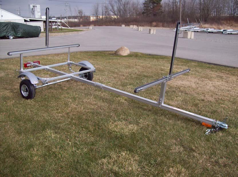
1 SUT-250-M2 ASSEMBLY REQUIREMENTS *Torque all T-bolt nuts to foot pounds. *Check all lights before towing. *Tire pressure not to exceed recommendation on serial tag. *Re-torque wheel nuts after first 25 miles to 80 ft pounds and periodically thereafter. Failure to follow the assembly instructions could result in serious injury or death. Incorrect assembly or modifications to your trailer will void any specific or implied warranty. For questions or assistance assembling your trailer call UNPACK AND IDENTIFY THE FOLLOWING PARTS. 1


2 Tongue sections. Axle and springs. Cross members & side rails. Front upright & cross bar assembly. Rear upright & cross bar assembly. Tongue to cross member angles. 2


3 Wheels, fenders, & hardware. Skid. Tail light brackets. 3


4 Frame assembly Lay the rear cross member on the floor. The two bolts mounted in the center will be facing the rear of the trailer. Locate the side rail with the bolt installed. With the bolt facing what will be the inside of the trailer, slide the side rail into the corner bracket from the rear. 4


5 Slide it all the way toward the front of the trailer until it is flush with the back edge of the rear spring hanger. Repeat for the other side. Do not tighten the triangular shaped corner brackets yet. Your frame should look like this. 5


6 Install the front cross member until the side rail is flush with the front edge of the front spring hanger. Square the frame and tighten all the corner brackets. 6


7 Optional step for spare tire carrier Slide 2 T-bolts on the underside of the front tongue section that has the serial number on it. Position carrier about 12 away from the splice plates then tighten nuts. 7
 in the side slots of the front tongue section.")

8 Tongue assembly Lay out the two tongue sections as shown. Locate the two T-bolts (one per side) in the side slots of the front tongue section. Loosen and slide them forward out of the way. These will be used later to install the front upright post. Align them end to end with the splice plates adjacent to each other. Loosen 4 nuts on each splice plate. 8


9 Slide each plate over the adjacent tongue section until the plates are centered over the gap between the tongue sections. Tighten all 8 nuts making sure that the tongue sections are as tight as possible to one another. 9


10 Frame Attachment Set the frame assembly on top of the tongue with the attaching brackets behind the cross members. Line up the tongue with the pencil marks on the rear cross member. Remove the nuts. 10


11 Locate the two remaining tongue brackets and install them as shown on the front and rear cross members. point. Your trailer should look like this at this 11


12 Spring Installation Locate the spring assemblies and lay them out with the shackle assemblies toward the rear of the trailer. Remove the bolt from the front spring eye and install the spring into the spring hanger in the center hole with the nut toward the inside of the trailer. Do not tighten yet. 12


13 Remove the two bolts from the shackle holder at the rear of the spring and install the shackle holder into the rear spring hanger with the nuts toward the inside of the trailer. These nuts can be tightened at this time. The springs should look like this when properly installed. Do not tighten the nuts yet. 13


14 Axle Installation Locate the axle and install it on the springs as shown. Make sure the locating studs on the springs are in the holes on the axle s spring seat. Face the axle s serial plate toward the rear of the trailer to protect it from debris. Locate the U-bolts and tie plates and install them as shown. Install the nuts and tighten them evenly. 14


15 Go back and tighten all of the spring mounting nuts that were left loose previously. On the rear shackle, do not over tighten as this will not allow the suspension to move properly. 15


16 Locate 8 lug nuts. Install the wheels with the valve stems facing out. Install the lug nuts with the tapered side facing the wheel. Tighten to 80 foot pounds in a crossing pattern. Re-tighten after 25 miles. Turn the trailer right side up. 16


17 Fender Installation Locate (2) 1 1/8 T-bolts from the hardware bag and install them into the side rails. Slide them into position over the tire and install two rubber washers and two steel washers as shown. Install the fender, two more steel washers, and nuts, center the fender over the tire and tighten the nuts. Repeat for the other side. 17


18 Rear Crossbar Installation Locate the two rear crossbar uprights. Loosen the nut located in the rear of the cross member and slide the bolt out. 18


19 Remove the nut from the T-bolt in the rear cross member and install the upright. Install the bolt and nut onto the side rail first then the nut onto the bolt in the rear cross member. Repeat for the other side. Locate the rear crossbar assembly. Remove the nuts from both bolts and remove one bolt. 19


20 Slide the rear upright into the slot and align it with the pencil marks in the center of the cross bar. Re-install the bolt that was previously removed and align the uprights with the pencil marks on the cross bar. Install the nuts. 20


21 Locate the square U-bolts and install one in the center upright and one in each end of the crossbar facing the rear of the trailer. The final location will be determined when the boats are loaded. 21


22 Front Crossbar Installation Remove the nut from the bolt in the top of front tongue section. Remove the nuts from the two bolts in the side of the front tongue section that you moved out of the way during the tongue assembly. Locate the front crossbar post and install it on the bolt 40 from the front of the trailer. This dimension is not critical as the final location will be determined by your boats. 22


23 Loosen or remove the nuts on the post bracket. Slide the bolts in the side of the tongue into position and install the bracket as shown. Tighten all the nuts. Remove the nuts from the crossbar and slide the crossbar down into the front post. Insert the bolts through the brackets and re-install the nuts. Tighten all three nuts. 23


24 Skid, Running light bracket, running lights. Slide the rear of the skid into the bottom slot in the front tongue section. Do not install the front of the skid yet. Locate the running light bracket with bolt and nut. Slide the running light bracket into the bottom slot in the front tongue section. 24


25 Slide the front of the skid into the bottom slot in the front tongue section. Tighten the nuts for the skid and running light bracket in the location shown. Locate the two amber running lights, four small Philips screws, and two ring terminals. Cut approximately 8 ½ off of the white wires on both running lights. Strip 1/4 of insulation from the wire. 25


26 Install the ring terminals by crimping the terminal onto the bare wire. Align the ring terminals with the screw hole nearest the wire on the back of the running light. Make sure the wire is routed through the gap on the back of the light so it does not become pinched when the light is installed. Install the running lights into the pre-drilled holes in the running light bracket using a Philips screwdriver. Be sure the screw is through the ring terminal on the back side of the lights. This will supply a ground to the lights. DO NOT OVER TIGHTEN 26


27 wires exiting the running lights. At this point there should be just 2 brown Tail Light Brackets, Tail lights Install the tail light brackets 8 from the rear of the tongue as shown. 27

 of the trailer.")


28 Locate the tail lights, carriage bolts, and nuts inside the light kit box. The light with the yellow wires is for the left (driver s side) of the trailer. back of the tail lights. Slide the carriage bolts into the slots in the Install the license plate bracket and left tail light onto the tail light bracket. Place the white ground wire from the tail light onto the carriage bolt. Repeat for the right side. 28


29 Wiring Locate the wire harness. Extend a tape measure inside the tongue from the rear of the trailer until it protrudes at the front of the trailer under the coupler. Attach both wires of the harness to the end of the tape measure using the ties provided with the harness. Retract the tape measure until it comes out of the back of the tongue with both wires attached. 29


30 Pull the excess wire out of the back of the tongue leaving approximately 18 of harness exposed at the front. Cut the white ground wire at the front of the trailer leaving it 22 long. Strip the wire and install a ring terminal as previously described. Locate the ¾ long Philips screw. Install the ground wire into the pre-drilled hole located under the tongue just behind the coupler. Locate the light blue tap connectors. Notice that one hole passes through and the other does not. 30


31 Cut 6 off of the brown wire on the left (driver s side) running light. Do not strip the wire. Insert it into the hole in the connector closest to the hinge. This hole does not pass all the way through. The wire should go in about ½. Pass the brown wire from the other running light through the remaining open slot in the connector at a point close to the running lights. (Illustration) Use pliers to push the metal spade down until it is flush with the plastic. This is what makes the electrical connection between the two wires. Close the plastic cover of the connector over the spade until it snaps into position. 31
 running light.")


32 Cut the exposed strands of wire off of the end of the brown wire on the right (passenger side) running light. Measure 22 back from the front plug on the green/brown wire and pass the brown wire through the open slot in the second light blue connector at this location. The green wire will rest just outside the connector. Insert the brown wire from the running lights into the closed side of the connector and close the spade and cover as previously described. This will make the connection from the main harness to both running lights. Locate an adhesive backed clamp. Install it in the location shown and run the brown wire from the running lights through it. 32


 Locate the black tab at the bottom of the right (passenger")
33 Pull the two wires at the back of the trailer through the tongue until there is approximately 18 protruding from the front. Cut the excess wire at the rear of the trailer leaving 12 exposed. (Disregard the black roller assembly in the following pictures, the SUT-250-M2 does have this roller.) Locate the black tab at the bottom of the right (passenger side) tail light. Move the tab toward the rear of the trailer and pull down releasing the bulb assembly from the light housing. 33


34 Loosen the wire retaining screws and install the color matching wires from the wire harness onto the corresponding retaining screws. Re-install the bulb assembly into the light housing making sure to route the wires through the slot in the base of the bulb assembly. Repeat for the left side. Install adhesive backed clamps in the locations shown and route the wires through them. 34

35 35 KJM REVISED 9/18/14
UNPACK AND IDENTIFY THE FOLLOWING PARTS.
 SUT-500-S ASSEMBLY REQUIREMENTS *Torque all T-bolt nuts to 35-40 foot pounds. *Check all lights before towing. *Tire pressure not to exceed recommendation on serial tag. *Re-torque wheel nuts after first
UNPACK AND IDENTIFY THE FOLLOWING PARTS.
 SUT-350-AIT ASSEMBLY REQUIREMENTS *Torque all T-bolt nuts to 35-40 foot pounds. *Check all lights before towing. *Tire pressure not to exceed recommendation on serial tag. *Re-torque wheel nuts after first
SUT-250-S (These instructions are used for SUT-250-SCLC also)
") SUT-250-S (These instructions are used for SUT-250-SCLC also) Torque wrench, carpenters square, wire cutters, Phillips screwdriver, 7/16, 9/16, and 3/4 combination wrenches, ratchet, 9/16, 3/4, 13/16,
SUT-250-S (These instructions are used for SUT-250-SCLC also) Torque wrench, carpenters square, wire cutters, Phillips screwdriver, 7/16, 9/16, and 3/4 combination wrenches, ratchet, 9/16, 3/4, 13/16,
SUT-450-I ASSEMBLY REQUIREMENTS
 SUT-450-I Torque wrench, carpenters square, wire cutters, Phillips screwdriver, 7/16, 9/16, and 3/4 combination wrenches, ratchet, 9/16,3/4,13/16, and 7/8 sockets. ASSEMBLY REQUIREMENTS *Torque all T-bolt
UT ASSEMBLY REQUIREMENTS. *Torque all T-bolt nuts to foot pounds.
 UT-1000-8-04 ASSEMBLY REQUIREMENTS *Torque all T-bolt nuts to 35-40 foot pounds. *Check all lights before towing. *Tire pressure not to exceed recommendation on serial tag. *Re-torque wheel nuts after
UT ASSEMBLY REQUIREMENTS. *Torque all T-bolt nuts to foot pounds.
 UT-1200-16-04 ASSEMBLY REQUIREMENTS *Torque all T-bolt nuts to 35-40 foot pounds. *Check all lights before towing. *Tire pressure not to exceed recommendation on serial tag. *Re-torque wheel nuts after
NORTHSTAR TRAILERS. Assembly Guide for SPORTSTAR II Trailer
 NORTHSTAR TRAILERS Assembly Guide for SPORTSTAR II Trailer Congratulations! You are the proud owner of a NORTHSTAR trailer. Please follow the instructions and steps in this manual for proper assembly.
NORTHSTAR TRAILERS. Assembly Guide for SPORTSTAR I Trailer
 NORTHSTAR TRAILERS Assembly Guide for SPORTSTAR I Trailer Congratulations! You are the proud owner of a NORTHSTAR trailer. Please follow the instructions and steps in this manual for proper assembly. We
NORTHSTAR TRAILERS. Assembly Guide for MULTISTAR Trailer
 NORTHSTAR TRAILERS Assembly Guide for MULTISTAR Trailer Congratulations! You are the proud owner of a NORTHSTAR trailer. Please follow the instructions and steps in this manual for proper assembly. TRAILER
<THESE INSTRUCTIONS MUST BE GIVEN TO THE END USER> B&W
 B&W Trailer Hitches 1216 Hawaii Rd / PO Box 186 Humboldt, KS 66748 P:620.473.3664 F:620.869.9031 Turnoverball Gooseneck Hitch Installation Instructions
PDF created with pdffactory trial version
 J 4628 MH 0-5-08 H 458 MH 05-2-08 DWG. REV. ECR/NDR NUMBER REVISED BY DATE 0-02 REPLACED 0-02205 (" TIRES); 0-02 REPLACED 0-02252 (4" TIRES); 00-0900 REPLACED 00-00999 0-069 WAS 0-0228.X 0.00.XXXX 0.00-2-06
PLEASE READ THIS INSTRUCTIONS CAREFULLY, BEFORE YOU START INSTALLATION
 INSTALLATION INSTRUCTIONS PART NUMBER: L0SXC000 DESCRIPTION: 09 ASCENT TRAILER HITCH PLEASE READ THIS INSTRUCTIONS CAREFULLY, BEFORE YOU START INSTALLATION SAFETY PRECAUTION: When installing Trailer Hitch,
GL1800 TRAILER HITCH - INSTALLATION INSTRUCTIONS #GL
 GL1800 TRAILER HITCH - INSTALLATION INSTRUCTIONS #GL18007-20 Read through these instructions completely before attempting installation, lay out all pieces including the numbered hardware bags to familiarize
<THESE INSTRUCTIONS MUST BE GIVEN TO THE END USER> B&W
 B&W Trailer Hitches 6 Hawaii Rd / PO Box 86 Humboldt, KS 66748 P:60.473664 F:60.869.903 Turnoverball Gooseneck Hitch Installation Instructions MODEL 08
1. Front Fascia Removal 1.1 Remove the 6 plastic clips that secure the upper valance, then remove. 1.2 Remove 6 upper bolts that hold the grille and f
 STRUT 2015 GMC Denali Collection Installation Manual " 1. Front Fascia Removal 1.1 Remove the 6 plastic clips that secure the upper valance, then remove. 1.2 Remove 6 upper bolts that hold the grille and
INSTALLATION INSTRUCTIONS
 INSTALLATION INSTRUCTIONS [1] Description: Tow Hitch Wire Harness Kit [2] Application: Nissan Rogue Note: Tow Harness application is limited to specific vehicle option packages that include tow harness
ECO# 1801 REVISION# 000 ES DATE
 SmokeShield Elevator ECO# 1801 REVISION# 000 ES 10-458 DATE 08/25/2018 ECO# 1801 REVISION# 000 ES 10-458 DATE 08/25/2018 Section 1 Table of Contents Section 2 Safety Check List 2 Section 3 Freight Receiving
SPORTSTER SADDLEBAG KIT. i i02212
 General These saddlebags are designed to fit 99 and later Sportster Model Motorcycles, except XL00 Sport models with gas reservoir shock absorbers and 88R models. See the Service Parts pages for a list
<THESE INSTRUCTIONS MUST BE GIVEN TO THE END USER> B&W
 B&W Trailer Hitches 1216 Hawaii Rd / PO Box 186 Humboldt, KS 66748 Turnoverball Gooseneck Hitch Installation Instructions MODEL 1314 2013 2014 RAM 3500
ST - HD - HDXL Model
 ST - HD - HDXL Model TOOLS REQUIRED FOR ASSEMBLY OF THE TANDEM TOW DOLLY Ratchet Socket Wrench with sockets sizes: 7/16, 9/16, 3/ 4 & 15/16 7/16 Box or Open End Wrench 9/16 Box or Open End Wrench 3/4 Box
FENDER ELIMINATOR. Remove axle nut, slide out axle, and drop rear tire away from the fender. (Picture 1)
") TRIUMPH BOBBER Remove axle nut, slide out axle, and drop rear tire away from the fender. (Picture ) Remove () tail light bolts. (Picture ) Unplug stock connectors and remove from underneath the fender.
TRIUMPH BOBBER Remove axle nut, slide out axle, and drop rear tire away from the fender. (Picture ) Remove () tail light bolts. (Picture ) Unplug stock connectors and remove from underneath the fender.
<THESE INSTRUCTIONS MUST BE GIVEN TO THE END USER> B&W Trailer Hitches 1216 Hawaii Rd / PO Box 186 Humboldt, KS P: F:
 B&W Trailer Hitches 6 Hawaii Rd / PO Box 86 Humboldt, KS 6678 P:60.7366 F:60.73766 Turnoverball Gooseneck Hitch Installation Instructions MODEL 38 0 06
ADDICTIVE DESERT DESIGNS
 Preparation: Disconnect the negative battery terminal. Park the vehicle on level ground and set the emergency brake. We recommend reading through the installation instructions in whole before performing
B300BTPAPL Fender Mounting Instructions for MIN300, MIN318 & 1021/302/202 Fenders
 B300BTPAPL Fender Mounting Instructions for MIN300, MIN318 & 1021/302/202 Fenders STEP 1 A. Unpack all cartons and lay out parts. B. Compare the parts with hardware kit B300BTPAPL as shown in Figure 1.
<THESE INSTRUCTIONS MUST BE GIVEN TO THE END USER> B&W
 B&W Trailer Hitches 1216 Hawaii Rd / PO Box 186 Humboldt, KS 66748 P:620.473664 F:620.869.9031 Turnoverball Gooseneck Hitch Installation Instructions
B4578BTPA Fender Mounting Instructions for MIN4000, MIN900, MIN1500 & MIN1554 Fenders
 STEP 1 B4578BTPA Fender Mounting Instructions for MIN4000, MIN900, MIN1500 & MIN1554 Fenders A. Unpack all cartons and lay out parts. B. Compare the parts with hardware kit B4578BTPA as shown in Figure
MODEL 2604 WARNING <THESE INSTRUCTIONS MUST BE GIVEN TO THE END USER> Custom 5th Wheel Hitch Mounting Rail Installation Instructions
 B&W Trailer Hitches 1216 Hawaii Rd / PO Box 186 Humboldt, KS 66748 P:620.473.3664 F:620.869.9031 Custom 5th Wheel Hitch Mounting Rail Installation Instructions
<THESE INSTRUCTIONS MUST BE GIVEN TO THE END USER> B&W
 B&W Trailer Hitches 6 Hawaii Rd / PO Box 86 Humboldt, KS 6678 P:60.7366 F:60.86.03 Turnoverball Gooseneck Hitch Installation Instructions MODEL 38 0 08
LGT-311L Bumper LED Light Kit EZ-Go RXV Installation Instructions
 LGT-311L Bumper LED Light Kit EZ-Go RXV Installation Instructions Caution: Please read through the instructions carefully. Before starting this project, remove the system s positive and negative connections
and Original Series Pickup Lift Mounting Instructions Fullsize Chevy & GMC Trucks: 1500 & 2500 LD HD & 3500HD BOLT-ON GUSSET
 r ve and Original Series Pickup Lift Mounting Instructions Fullsize Chevy & GMC Trucks: 1500 & 2500 LD 1999-2007 2500HD & 3500HD 2000-2007 Preparing the Gate 1. Remove the mounting hardware which is banded
and Original Series Pickup Lift Mounting Instructions T-150-T T-150 PART#5177 T-150-T
 Fullsize Chevy & GMC Trucks- 988-999 Toyota Tundra- 2000-2006 Toyota T-00-993-999 Preparing the Gate r ve and Original Series Pickup Lift Mounting Instructions. Remove the mounting hardware which is banded
INSTALLATION INSTRUCTIONS For 65800, 65801, 66355, 69250, Rear Bumper And Tire Carrier For Jeep XJ Cherokee
 INSTALLATION INSTRUCTIONS For 65800, 65801, 66355, 69250, 69251 Rear Bumper And Tire Carrier For Jeep XJ Cherokee Your safety, and the safety of others, is very important. To help you make informed decisions
INSTALLATION INSTRUCTIONS SEMI-HIDDEN WINCH MOUNT Part Number:70005 Application: Ford Super Duty
 INSTALLATION INSTRUCTIONS SEMI-HIDDEN WINCH MOUNT Part Number:70005 Application: Ford Super Duty Your safety, and the safety of others, is very important. To help you make informed decisions about safety,
POLY TIP-DOWN WINDSHIELD KIT
 POLY TIP-DOWN WINDSHIELD KIT P/N 2883261 APPLICATION Verify accessory fitment at Polaris.com. BEFORE YOU BEGIN Read these instructions and check to be sure all parts and tools are accounted for. Please
INSTALLATION INSTRUCTIONS DOCUMENT REVISION : /17/2014
 INSTALLATION INSTRUCTIONS DOCUMENT REVISION : 1.0 10/17/2014 LPF COMPONENT LIST LPF W/ WIRE & GROMMET ( 1 ) M6 X 20MM SCREW ( 2 )* LPF DRIVER BOX ( 1 ) REVERSE CIRCUIT WIRE ( 1 ).25 THICK LICENSE PLATE
INSTALLATION MANUAL
 INSTALLATION MANUAL 2563000 Parts List 1 Carrier weldment 2 Support arm assembly 1 Third brake light assembly 1 Light extension bracket 1 Spare tire adjustment plate 1 Spare tire mount plate 1 Female spade
and Original Series Pickup Lift Mounting Instructions Fullsize Nissan Titan Trucks present T-420 BOLT-ON GUSSET PART#5257
 and Original Series Pickup Lift Mounting Instructions Fullsize Nissan Titan Trucks- 2004-present Preparing the Gate 1. Remove the mounting hardware which is banded to the liftgate. 2. Verify mounting bracket
KARAVAN T R A I L E R S
 C 0 MJH B 036 KMH 06--2 04-0-0 ADDED (4)2-0036. REPLACED 8-0003 WITH 8-00049; -0002 WITH -00 - (2X); -00046 WITH -00330; -0004 WITH -0006; -00048 WITH -0006.X 0.00.XXXX 0.00 OF NOTES:.) WINCH SHOULD BE
650 Series Cargo Van Lift Mounting Instructions Ford Transit (Standard Roof) 2015-Present
 2015-Present") TOMMY GATE OWNER'S / OPERATOR'S MANUAL 650 Series 650 LB Capacity 650 Series Cargo Van Lift Mounting Instructions Ford Transit (Standard Roof) 2015-Present Installing the Base Plate 1. Examine the interior
TOMMY GATE OWNER'S / OPERATOR'S MANUAL 650 Series 650 LB Capacity 650 Series Cargo Van Lift Mounting Instructions Ford Transit (Standard Roof) 2015-Present Installing the Base Plate 1. Examine the interior
and Original Series Pickup Lift Mounting Instructions Fleetside Chevy & GMC Trucks Fleetside 4-door Chevy & GMC Trucks T-100
 r ve and Original Series Pickup Lift Mounting Instructions Fleetside Chevy & GMC Trucks - 1960-1987 Fleetside 4-door Chevy & GMC Trucks - 1988-1991 Preparing the Gate 1. Remove the mounting hardware which
SAFETY. Read and understand all safety precautions and instructions before installing this product.
 SAFETY Your safety and the safety of others is very important. In order to help you make informed decisions about safety, we have provided installation instructions and other information. These instructions
80703 & Backside License Plate Mount for Jeep JK Wrangler (80707) & 10+ (80703)
 & 10+ (80703)") 80703 Backside Mount 80707 Backside Mount REQUIRED TOOLS 10mm SOCKET 13mm SOCKET 4mm HEX KEY WIRE CRIMPS WIRE STRIPPERS ELECTICAL TAPE SCREW DRIVER KIT CONTAINS BACKSIDE MOUNT LICENSE PLATE BRACKET WITH
80703 Backside Mount 80707 Backside Mount REQUIRED TOOLS 10mm SOCKET 13mm SOCKET 4mm HEX KEY WIRE CRIMPS WIRE STRIPPERS ELECTICAL TAPE SCREW DRIVER KIT CONTAINS BACKSIDE MOUNT LICENSE PLATE BRACKET WITH
LPE C5 Battery Relocation Kit
 LPE C5 Battery Relocation Kit The LPE C5 Corvette battery relocation kit improves vehicle weight distribution by moving weight to the rear of the vehicle. The improved weight distribution increases traction
LittleGiant Trailer Harley Hauler Kit
 3380 N. El Paso St., Colorado Springs, CO 80907 LittleGiant Trailer Harley Hauler Kit User Assembly Manual Visit our website at www.letsgoaero.com For Assistance, please call 1-877-464-2376 or 719-630-3800
SAFETY THIS PRODUCT IS FOR OFFROAD USE ONLY. ALL LIABILITY FOR INSTALLATION AND USE RESTS WITH THE OWNER.
 SAFETY Your safety and the safety of others is very important. In order to help you make informed decisions about safety, we have provided installation instructions and other information. These instructions
Required tools General hand tools 21/64" drill bit Torque wrench Threadlocker Center punch
 Slipper Spring Kit (part numbers 2560, 2570 and 2580) Item Qty Part number Description 1... 8... 350054-50...3/8-16 x 1" grade 8 self-tapping screw 2... 4... 350084-00...7/16-14 x 4" grade 5 3... 6...
INSTALLATION INSTRUCTIONS
 REV 1 05/04/2017 INSTALLATION INSTRUCTIONS PART NO. 24388T PRODUCT DESCRIPTION: FRONT BUMPER REPLACEMENT APPLICATION: TOYOTA TACOMA PRODUCT SAFETY & LEGAL DISCLAIMER IMPORTANT READ ALL INSTRUCTIONS CAREFULLY
POLY TIP-DOWN WINDSHIELD KIT
 POLY TIP-DOWN WINDSHIELD KIT P/N 2881919 APPLICATION Verify accessory fitment at Polaris.com. BEFORE YOU BEGIN Read these instructions and check to be sure all parts and tools are accounted for. Please
GENUINE PARTS INSTALLATION INSTRUCTIONS
 GENUINE PARTS INSTALLATION INSTRUCTIONS 1. 2. 3. DESCRIPTION: APPLICATION: PART NUMBER: Accent light Kit Cube (MY2013+) 999F3 AW000 - Universal Accent Lighting Kit. 4. KIT CONTENTS: Item QTY Description
3 MULTI PURPOSE TRAILER KIT ASSEMBLY GUIDE. Free Call
 ASSEMBLY GUIDE MODEL: AT6096G WARNING: Read and understand the owner's manual completely before you use the trailer. 3 MULTI PURPOSE TRAILER KIT ASSEMBLY GUIDE SAVE THIS GUIDE & MANUAL You will need this
INSTALLATION INSTRUCTIONS
 INSTALLATION INSTRUCTIONS Models: 7105 & 7105TK Dodge Ram 1500 ('02 Current) Ram 2500 & 3500 '03 - Current with stock manual mirrors. IF YOU DO NOT CURRENTLY HAVE MANUAL MIRRORS, THE WRONG SET HAS BEEN
Land Cruiser FJ80 and FZJ80 Double Swingout Rear Bumper Installation Instructions PRELIMINARY
 Land Cruiser FJ80 and FZJ80 Double Swingout Rear Bumper Installation Instructions Fits 1991-1997 80 Series Land Cruiser / Lexus LX450 PRELIMINARY Thank you for purchasing a Rear Bumper for your Land Cruiser.
GrilleGuy.com, LLC. Installation Instructions and Care Guide : Toyota Tacoma Grille UPPER GRILLE
 Installation Instructions and Care Guide : 2001 2004 Toyota Tacoma Grille Thanks again for purchasing your custom grille insert from GrilleGuy.com. The following are some general guidelines that will simplify
INSTALLATION / OPERATING INSTRUCTIONS Reese Elite Series FIFTH WHEEL SLIDER HITCH
 INSTALLATION / OPERATING INSTRUCTIONS Reese Elite Series FIFTH WHEEL SLIDER HITCH DEALER/INSTALLER: (1) Provide this Manual to end user. (2) Physically demonstrate hitching and unhitching procedures in
Backside License Plate Mount for Jeep JK Wrangler
 REQUIRED TOOLS 10mm SOCKET 13mm SOCKET 4mm HEX KEY WIRE CRIMPS WIRE STRIPPERS ELECTICAL TAPE SCREW DRIVER KIT CONTAINS BACKSIDE MOUNT LICENSE PLATE BRACKET WITH LEDS PLASTIC PASS-THROUGH GROMMET STAINLESS
A B C D E F. Tools Required (supplied by others)
") Page 1 of 17 Parts List Below Deck Automatic Retractable Security Cover Kit (1) Tube End Bearing Plate (A) (1) Rope Reel and Cover Drum Motor Assembly (B) (1) Cover Drum (1) Pulley Support Channel (2)
Page 1 of 17 Parts List Below Deck Automatic Retractable Security Cover Kit (1) Tube End Bearing Plate (A) (1) Rope Reel and Cover Drum Motor Assembly (B) (1) Cover Drum (1) Pulley Support Channel (2)
T-52. r ve Pickup Lift Mounting Instructions Chevy / GMC- Colorado/ Canyon: 2015-present. Preparing the Gate. Installing the Bolt-on Gussets
 Chevy / GMC- Colorado/ Canyon: 2015-present Preparing the Gate 1. Remove the mounting hardware which is banded to the liftgate. 2. Verify mounting bracket kit (Figure 1 and Table 1). LEFT BRACKET (RIGHT
LGT-312L E-Z-Go TXT Light Bar Bumper Kit Installation Instructions
 LGT-312L E-Z-Go TXT 2014+ Light Bar Bumper Kit Installation Instructions Caution: Please read through the instructions carefully. Before starting this project, remove the system s positive and negative
At-A-Glance Trailer Assembly Overview
 At-A-Glance Trailer Assembly Overview VERY IMPORTANT; ALWAYS REFER TO YOUR OWNER S MANUAL FOR PROPER OPERATING AND SAFETY INFORMATION REGARDING YOUR TRAILER. INCASE OF LOSS GO TO WWW.UTILITYMATE.COM BEFORE
INSTALLATION INSTRUCTIONS
 INSTALLATION INSTRUCTIONS OUTLAW REAR BUMPER APPLICATION: 2016-2018 Chevrolet Silverado 1500 PART NUMBER: 58-81005 CONTENT ITEM QUANTITY DESCRIPTION TOOLS NEEDED 1 1 REAR BUMPER 18MM WRENCH 2 4 SENSOR
LIFT-304 (3 ) and LIFT-104 (6 ) Drop Spindle Lift Kits Yamaha G22, Gas or Electric Installation Instructions
 and LIFT-104 (6 ) Drop Spindle Lift Kits Yamaha G22, Gas or Electric Installation Instructions") LIFT-304 (3 ) and LIFT-104 (6 ) Drop Spindle Lift Kits Yamaha G22, Gas or Electric Installation Instructions LIFT-304 LIFT-104 Contents of LIFT-304/104 Yamaha G22 Lift Kit: a (1 ea.) Passenger Side Spindle
LIFT-304 (3 ) and LIFT-104 (6 ) Drop Spindle Lift Kits Yamaha G22, Gas or Electric Installation Instructions LIFT-304 LIFT-104 Contents of LIFT-304/104 Yamaha G22 Lift Kit: a (1 ea.) Passenger Side Spindle
Automatic Roof Hatch Opener
 Automatic Roof Hatch Opener Installation Guide REQUIRED TOOLS (These tools are required to complete the installation) Cordless Drill 1/8 1/4 Drill Bits 1/8 Pin Punch #2 Philips Bit Rachet Sharpie Hammer
SAFETY THIS PRODUCT IS FOR OFFROAD USE ONLY. ALL LIABILITY FOR INSTALLATION AND USE RESTS WITH THE OWNER.
 SAFETY Your safety and the safety of others is very important. In order to help you make informed decisions about safety, we have provided installation instructions and other information. These instructions
Installation instructions, accessories. Body kit
 Installation instructions, accessories Instruction No 31265373 Version 1.1 5 Part. No. Body kit IMG-256263 Volvo Car Corporation Body kit - 31265373 - V1.1 Page 1 / 42 Equipment A0000162 A0000163 IMG-239664
** DO NOT EXCEED THE RECOMMENDED VEHICLE TOWING WEIGHT RATING ** DODGE RAM 1500
 10/3/2017 DODGE RAM 1500 WARNING!! BRAKE, FUEL, AND ELECTRICAL LINES MAY NEED TO BE LOOSENED OR REPOSITIONED TO PROVIDE CLEARANCE FOR NEW HARDWARE. ON SHORT BED MODELS, CHECK FOR ADEQUATE TURNING CLEARANCE
B4850BTPACF Fender Mounting Instructions for MIN4050, MIN950 & MIN1550 Fenders
 B4850BTPACF Fender Mounting Instructions for MIN4050, MIN950 & MIN1550 Fenders STEP 1 A. Unpack all cartons and lay out parts. B. Compare the parts with hardware kit B4850BTPA as shown in Figure 1. B4850BTPACF
UtilityMate Trailer Kit Assembly Guide
 ASSEMBLY GUIDE MODELS UM5806 AND 5288 IMPORTANT: Read the Owner s Manual completely before you use the trailer. UtilityMate Trailer Kit Assembly Guide At-A-Glance Trailer Assembly Overview 1. 2. 3. 1.
2014 GM 1500 TRUCK STOP---READ THIS FIRST! 7" Lift KIT. **Read These Entire Instructions Before Starting Anything**
 STOP---READ THIS FIRST! **Read These Entire Instructions Before Starting Anything** 2014 GM 1500 TRUCK LIFT KIT INSTRUCTIONS (PART #50768 & #50769 ) 5680 W. Barstow, Fresno, CA 93722 PH: (559) 226-8196
Universal Tall HoneyBadger Chase Rack Installation Instructions
 PREPARATION Universal Tall HoneyBadger Chase Rack Installation Instructions 1. Disconnect the negative terminal on the battery. Park the vehicle on level ground and set the emergency brake. 2. We recommend
SAFETY. Read and understand all safety precautions and instructions before installing this product.
 SAFETY Installation Instructions Application: 2015+ FORD F150 Your safety and the safety of others is very important. In order to help you make informed decisions about safety, we have provided installation
baseplate Chevrolet Equinox
 , Rev 3 06/16 baseplate 9518316 Chevrolet Equinox Pin height - 14-3/4 Centers - 24-1/4 25. ITEM PART # QTY DESCRIPTION 1 00057 2.25 LOCKWASHER 2 00059 8.375 FLATWASHER 3 00060 24.375 LOCKWASHER 4 00061
IL500 Sierra Inclined Platform Lift
 IL500 Sierra Inclined Platform Lift Installation & Service Manual www.harmar.com 800-833-0478 IMPORTANT: Read and understand this manual thoroughly before attempting to install or operate the lift. If
INSTALLATION INSTRUCTION
 620 Magnolia Ave. Suite B Ontario, CA 91762 (909) 923-1973 INSTALLATION INSTRUCTION Club Car Precedent Lithium Battery Pack Installation Notes Including Cars with Installed HPEVS Drive Systems REVISION:
Assembly Instructions
 Assembly Instructions Part Number Description Model Approx. Assembly Time 99994-0903 Windshield Wiper Kit Mule SX 1 Hour WARNING Improper installation of this accessory could result in an accident causing
DVS Cypress Face Installation Instructions (SKU )
") Table of Contents Compatibility... 1 Packing List... 1 Installation... 2 Prepare the Insert for Face Installation... 2 Attach the Surround Panels (if applicable)... 6 Assemble the Face... 7 Attach the
Table of Contents Compatibility... 1 Packing List... 1 Installation... 2 Prepare the Insert for Face Installation... 2 Attach the Surround Panels (if applicable)... 6 Assemble the Face... 7 Attach the
G-170. r ve Pickup Lift Mounting Instructions Fullsize Chevy & GMC Trucks- 1500, 2500 & 3500: 2007-present
 Fullsize Chevy & GMC Trucks- 1500, 2500 & 3500: 2007-present Preparing the Gate 1. Remove the mounting hardware which is banded to the liftgate. 2. Verify mounting bracket kit (Figure 1 and Table 1). 18-5/8"
Suzuki Samurai to Toyota Front Spring Swap Kit, with Missing Link Shackles (SKU#SSP-TSFM) Installation Instructions
 Installation Instructions") Suzuki Samurai to Toyota Front Spring Swap Kit, with Missing Link Shackles (SKU#SSP-TSFM) Installation Instructions CAUTION: Safety glasses should be worn at all times when working with vehicles and related
Suzuki Samurai to Toyota Front Spring Swap Kit, with Missing Link Shackles (SKU#SSP-TSFM) Installation Instructions CAUTION: Safety glasses should be worn at all times when working with vehicles and related
TOYOTA VENZA 2009 TRAILER WIRE HARNESS Procedure
 Part Number: PT791-0T099 Kit Contents Item # Quantity Reqd. Description 1 1 Trailer Wire Harness Module 2 1 4-Flat Harness 3 1 Battery Power Wire Harness 4 1 Mounting Bracket, 4-Flat 5 2 Screw #10-24 6
GENUINE PARTS INSTALLATION INSTRUCTIONS
 GENUINE PARTS INSTALLATION INSTRUCTIONS 1. 2. 3. 4. DESCRIPTION: Accent light Kit APPLICATION: Infiniti JX (2013) PART NUMBER: 999F3 YY000 - Universal Accent Lighting Kit. KIT CONTENTS: Item QTY Description
BX8848 Installation Instructions 4 Diode Wiring Kit For Motorhomes With Red Tail Lights
 For Motorhomes With Red Tail Lights WARNG: Incorrect wiring may result in blown fuses, damaged wiring, fire, or bodily injury. Blue Ox recommends installation of this kit by a trained professional. Blue
Section 5: Parts Replacement
 Section 5: Parts Replacement Should the STAR TRAC 4500 Treadmill experience a problem requiring replacement of a specific part, the following procedures will help and instruct in the replacement of major
PLEASE READ THESE INSTRUCTIONS CAREFULLY, BEFORE YOU START INSTALLATION
 PART NUMBER: L0SSJ000 INSTALLATION INSTRUCTIONS DESCRIPTION: FORESTER TRAILER HITCH PLEASE READ THESE INSTRUCTIONS CAREFULLY, BEFORE YOU START INSTALLATION SAFETY PRECAUTION: When installing Trailer Hitch,
Haul-Your-Might T3. Product Name: Product Code: Please read all instructions carefully before assembly, installation and/or use of this product.
 WARNING: DO NOT exceed 800 lbs. (363 Kgs) WARNING: DO NOT exceed vehicle manufacturer s weight rating. Tools Required: 17mm Socket 5mm Hex Key 1/8 Hex Key Tape Measure 17mm Wrench 13mm Socket Hack Saw
SAFETY. Injury hazard
 SAFETY Your safety and the safety of others is very important. In order to help you make informed decisions about safety, we have provided installation instructions and other information. These instructions
650 Series Cargo Van Lift Mounting Instructions Fullsize Ford 1992-Present
 TOMMY GATE OWNER'S / OPERATOR'S MANUAL 650 Series 650 LB Capacity 650 Series Cargo Van Lift Mounting Instructions Fullsize Ford 1992-Present Installing the Base Plate 1. Examine the interior and exterior
TOYOTA im INTERIOR LIGHT KIT Preparation
 Preparation Part Number: PT922-12170 Kit Contents Item # Quantity Reqd. Description 1 1 Main Wire Harness 2 1 Switch 3 1 Switch Header 4 1 ECU 5 1 ECU Bracket 6 1 Hardware Kit 7 1 Instruction Card 8 1
INSTALLATION INSTRUCTIONS
 PART NO. 23100T PRODUCT DESCRIPTION: Front Winch Bumper, Center Section PRODUCT SAFETY & LEGAL DISCLAIMER IMPORTANT READ ALL INSTRUCTIONS CAREFULLY BEFORE INSTALLING, FAILURE TO DO SO MAY CAUSE PERSONAL
GROSS LOAD CAPACITY WHEN USED AS A WEIGHT CARRYING HITCH: 2,000 LBS. TRAILER WEIGHT & 200 LBS. TONGUE WEIGHT.
 PAGE 1 0F 6 GROSS LOAD CAPACITY WHEN USED AS A WEIGHT CARRYING HITCH: 2,000 LBS. TRAILER WEIGHT & 200 LBS. TONGUE WEIGHT. WARNING: ALL NON-TRAILER LOADS APPLIED TO THIS PRODUCT MUST BE SUPPORTED BY 18050
GENUINE PARTS INSTALLATION INSTRUCTIONS
 GENUINE PARTS INSTALLATION INSTRUCTIONS 1. 2. 3. 4. DESCRIPTION: Accent light Kit APPLICATION: R42H (2011) PART NUMBER: 999F3 AW000 - Universal Accent Lighting Kit. KIT CONTENTS: Item QTY Description Service
2. With the rear door open remove pull-style clip from the passenger side just below the door latch.
 LoD Offroad FJ Cruiser Rear Bumper with Tire Carrier Installation Instructions 1. Begin with removing factory spare from the rear door. 2. With the rear door open remove pull-style clip from the passenger
R O A D S M I T H TRIKE CONVERSIONS BY THE TRIKE SHOP
 R O A D S M I T H TRIKE CONVERSIONS BY THE TRIKE SHOP Please thoroughly review the instructions before and during installation. Keep in mind that this product was designed to be installed by trained dealer
SAFETY THIS PRODUCT IS FOR OFFROAD USE ONLY. ALL LIABILITY FOR INSTALLATION AND USE RESTS WITH THE OWNER.
 SAFETY Your safety and the safety of others is very important. In order to help you make informed decisions about safety, we have provided installation instructions and other information. These instructions
GENUINE PARTS INSTALLATION INSTRUCTIONS
 GENUINE PARTS INSTALLATION INSTRUCTIONS 1. 2. 3. 4. DESCRIPTION: APPLICATION: PART NUMBER: KIT CONTENTS: Accent light Kit Versa Note 999F3 4Z000 - Accent Lighting Kit. 999Q9 AY000 - Accessory Service Connector
PONTIAC FIREBIRD
 1974-78 PONTIAC FIREBIRD Two Panel Sequential LED Tail Light Kit Installation Guide Kit Contents: 2 LED panels 2 LED panel mount kits 6 rubber grommets 1 power wire 1 pigtail harness Kit 1 crimp terminal
LoD Offroad. Jeep JK Rear Bumper with Tire Carrier Installation Instructions
 LoD Offroad Jeep JK Rear Bumper with Tire Carrier Installation Instructions Please read through the instructions before beginning any part of the installation process. Packaging List: 1-Rear Bumper 1-Tire
Adjustable Light Kits E-Z-Go TXT All Models Installation Instructions
 Adjustable Light Kits E-Z-Go TXT All Models 1996-2013 Installation Instructions Caution: Please read through the instructions carefully. Before starting this project, remove the system s positive and negative
Assembly Instructions
 Assembly Instructions SP-7000 Serial No. 140410300001SP-7000 and higher Madison Heights, Michigan 48071 800-SALTERS www.snowexproducts.com CUSTOMER COPY TrynEx International 2014 F51558 REV-A140905 1 Introduction
ASSEMBLY INSTRUCTIONS & OWNERS MANUAL. McCONKEY INC. P.O. Box 1362 Seeley Lake, MT Phone: (308)
") ASSEMBLY INSTRUCTIONS & OWNERS MANUAL McCONKEY INC. P.O. Box 1362 Seeley Lake, MT 59868 Phone: (308) 641 2058 www.atvbackpackercart.com 1 Do not operate your ATV on steep or uneven terrain while the cart
ASSEMBLY INSTRUCTIONS & OWNERS MANUAL McCONKEY INC. P.O. Box 1362 Seeley Lake, MT 59868 Phone: (308) 641 2058 www.atvbackpackercart.com 1 Do not operate your ATV on steep or uneven terrain while the cart
Fender Mounting Instructions for MIN100, MIN150, MIN1600, MIN161200, MIN1900, MIN2200, MIN221800, MIN2260, MIN2480 & MIN9950 Fenders
 STEP 1 100126 Fender Mounting Instructions for MIN100, MIN150, MIN1600, MIN161200, MIN1900, MIN2200, MIN221800, MIN2260, MIN2480 & MIN9950 Fenders A. Unpack all cartons and lay out parts. B. Compare the
INSTALLATION INSTRUCTION
 1551 S. Vineyard Avenue Ontario, CA 91761 (909) 923-1973 INSTALLATION INSTRUCTION Club Car Precedent Installation Notes CURTIS 1234, 1236 OR 1238 AC INDUCTION MOTOR/ CONTROLLER REVISION: B This kit is