Single Pole Circuit Protectors 67 Multi-Pole Circuit Protectors 68 Printed Circuit Board Mounting 70 Configurations 72 Operating Characteristics 73
|
|
|
- Adela Ellis
- 6 years ago
- Views:
Transcription
1

2 Single Pole Circuit Protectors 67 Multi-Pole Circuit Protectors 68 Printed Circuit Board Mounting 70 Configurations 72 perating Characteristics 73 Delay Curves 74 Specifications 76 Decision Tables 78

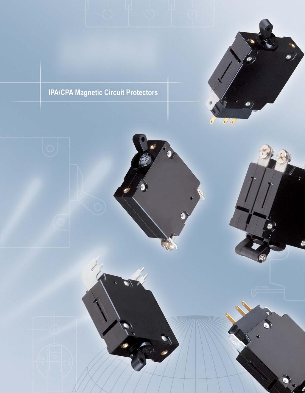
3 SIGLE PLE CIRCUIT PRTECTRS ITRDUCTI The Magnetic Circuit Protectors provide low-cost power switching, reliable circuit protection and accurate circuit control for equipment in the international marketplace. IPA models meet IEC spacing requirements that are mandatory for equipment which must comply with IEC specifications 60 and 950 and VDE specifications 0804 and In addition, they are UL Recognized as Supplementary Protectors per UL 077, CSA Certified as Supplementary Protectors, per CSA 22.2 o. 235, TUV Approved to VDE 0642 (E60934), CCC Approved (pending) and CE Compliant. Designed using the latest in sensitive hydraulic magnetic technology, the IPA line adapts itself to many applications and environments. They re ideal for data processing and business machines, medical instrumentation, broadcast equipment, vending and amusement machines, military applications and wherever precision operation is required. ne important feature of this protector line is a trip free action, which means the circuit will trip in the presence of an overload even though the handle is held in the position. The delay mechanism senses the fault and the contacts open. The IPA is available in configurations including series and series with auxiliary switch, with a choice of delays and ratings in either DC, 50/60Hz or 400Hz versions. Single or multi-pole versions are available, with a variety of pole arrangements to meet your specifications. Single Pole Breaker (one handle) LIE.732 [43.99].988 MAX. [50.50].635 [6.3].098 [2.49] [5.79] Ø.535 [3.59].654 [42.0].982 [24.94] 2X M3/ MAX. [4.9] Mounting Detail Ø.55 [4.00] 2X Ø.57 [3.99].260 [32.00].640 MAX. [6.26].260 [32.00].787 [9.99] otes:. Tolerance ±.05 [.38] unless noted. Dimensions in brackets [ ] are millimeters. 2. Main circuit protector terminals are stationary male push-on type:.248 [6.30] wide x.03 [.787] thick x.474 [2.00] long, or screw type: M4 x.354 [8.99] wide x.03 [.787] thick x.474 [2.00] long. Single Pole Magnetic Circuit Protectors 67

4 MULTI-PLE CIRCUIT PRTECTRS Two Pole Protectors An assembly consisting of two single pole units, having their trip mechanisms internally coupled and with a single toggle handle, forms the IPA- with quick-connect D.I..-style terminals. Individual poles may differ in ratings, delays and internal connections. An auxiliary switch may be included in either or both poles, allowing you to mix SELV and hazardous voltages. Rugged screw-type terminals can be provided, in which case the designation would be IPA-66. The IPAH offers a toggle handle for each pole. Three Pole Protectors The three pole construction consists of three single pole units assembled with an internal mechanical interlock which actuates all units simultaneously. A single toggle handle operates all three poles for quick and convenient control, or if preferred, a handle per pole is available. The individual poles need not have identical characteristics and any series trip pole may have an auxiliary switch. If screw-type terminals are required, the protector designation will be IPA-666 for a three pole version. Protector poles are numbered consecutively when viewed from the terminal side, with the position up, starting with Pole # on the left side and proceeding to the right. Handles The IPAH two and three pole models are available with a handle per pole. Two Pole Breakers (one handle) Three Pole Breakers (one handle).295 MAX. [32.89].935 MAX. [49.5] Mounting Details Two Pole Ø.55 Three Pole Ø.55 ote: Tolerance ±.05 [.38] unless noted. Dimensions in Brackets [ ] are millimeters..630 [6.00].630 [6.00].630 [6.00] 68 Multi-Pole Magnetic Circuit Protectors
![IPAH/CPAH Two Pole Breakers (two handles) Three Pole Breakers (three handles).295 MAX. [32.89].935 MAX. [49.5] Mounting Details Single Pole Ø.](/docs-images/75/72673234/images/5-0.jpg "55 Three Pole ote: Tolerance ±.05 [.38] unless noted. Dimensions in Brackets [ ] are millimeters..630 [6.00].630 [6.00].630 [6.00] Multi-Pole Magnetic Circuit Protectors 69")
5 IPAH/CPAH Two Pole Breakers (two handles) Three Pole Breakers (three handles).295 MAX. [32.89].935 MAX. [49.5] Mounting Details Single Pole Ø.55 Three Pole ote: Tolerance ±.05 [.38] unless noted. Dimensions in Brackets [ ] are millimeters..630 [6.00].630 [6.00].630 [6.00] Multi-Pole Magnetic Circuit Protectors 69
![PRITED CIRCUIT BARD MUTED CIRCUIT PRTECTRS.47 [35.99].654 [42.0].8 [3.0].35 [8.00] Printed Circuit Board Mounting Terminal Type S Printed Circuit Board Mounting Terminal Type R.35 [8.00].47 [35.99].492 [2.](/docs-images/75/72673234/images/6-0.jpg "50].047 [.20].97 [5.00].57 [3.99].38 [3.5].047 [.9].97 [5.00] 2.354 [59.79].047 [.9].79 [45.49].020 [0.5].03 [0.80] Mounting Detail.535 [3.59] 4X Ø.075 [.90] HADLE CETER.38 [3.5].03 [0.79].850 [2.")
6 PRITED CIRCUIT BARD MUTED CIRCUIT PRTECTRS.47 [35.99].654 [42.0].8 [3.0].35 [8.00] Printed Circuit Board Mounting Terminal Type S Printed Circuit Board Mounting Terminal Type R.35 [8.00].47 [35.99].492 [2.50].047 [.20].97 [5.00].57 [3.99].38 [3.5].047 [.9].97 [5.00] [59.79].047 [.9].79 [45.49].020 [0.5].03 [0.80] Mounting Detail.535 [3.59] 4X Ø.075 [.90] HADLE CETER.38 [3.5].03 [0.79].850 [2.59] Mounting Detail.97 [5.00] 9X Ø.075 [.90] HADLE CETER.406 [0.3].535 [3.59] (Auxiliary switch is not recommended with this type mounting.) ote: Tolerance ±.05 [.38] unless noted. Dimensions in brackets [ ] are millimeters..492 [2.50].246 [6.25].803 [45.80] [59.99].240 [6.0].97 [5.00].46 [.7].850 [2.59] 70 Printed Circuit Board Mounted Magnetic Circuit Protectors
7 Printed Circuit Board Mounting Terminal Type L.492 [2.50].047 [.20].38 [3.5].03 [0.79].38 [3.5].03 [0.80].97 [5.00] [59.79].047 [.9].79 [45.49].020 [0.5] Mounting Detail.535 [3.59].406 [0.3] 9X Ø.075 [.90] HADLE CETER.492 [2.50].850 [2.59].46 [.7].240 [6.0].97 [5.00] [59.99].803 [45.80].246 [6.25] ote: Tolerance ±.05 [.38] unless noted. Dimensions in brackets [ ] are millimeters. Printed Circuit Board Mounted Magnetic Circuit Protectors 7
8 CIGURATIS Series Trip The most popular configuration for magnetic protectors is the series trip where the sensing coil and contacts are in series with the load being protected. In addition to providing conventional overcurrent protection, the handle position conveniently indicates circuit status. Series Trip.383 [35.3].35 [3.43] LIE LIE LAD Switch LAD Series Auxiliary Switch (Applies to Series Trip nly) This is furnished as an integral part of a series pole in single or multi-pole assemblies. Isolated electrically from the protector s circuit, the switch works in unison with the power contacts and provides indication at a remote location of the protector s on-off status. Auxiliary switch contacts actuate simultaneously with the main protector contacts, and will open regardless of whether the protector contacts are opened manually or electrically. or auxiliary switch ratings below 6Vac or 5Vdc, an auxiliary switch with gold contacts, designated as REG, is available. Gold contacts are not recommended for load current above 00 milliamps. An optional auxiliary switch, RS, configuration allows an alarm or signal to be forwarded only upon electrical overload, allowing for easier detection of fault circuit. Series with Auxiliary Switch.729 MAX. [8.52].383 [35.3].05 [25.77].369 [9.37].775 [9.68] C C LIE.377 [9.58].024 [26.00] LIE LIE LIE C C C C LAD C LAD C LAD C-C = Breaker in position. Series with Auxiliary Switch Breaker in or manually turned position. Breaker in electrically tripped position. Auxiliary Alarm Switch (IRS4, IRSG4) otes:. Main circuit protector terminals are stationary male push-on type:.248 [6.30] wide x.03 [.787] thick x.474 [2.00] long, or screw type: M4 x.354 [8.99] wide x.03 [.787] thick x.474 [2.00] long. 2. Auxiliary switch terminals are:.0 [2.79] wide x.020 [0.5] thick x.343 [8.7] long. 3. Tolerance ±.05 [.38] unless noted. Dimensions in brackets [ ] are millimeters. 72 Configurations
9 PERATIG CHARACTERISTICS Agency Approvals Voltage (V) Rated Current (A) Minimum/Maximum Interrupting Capacity, Amps IPA Max Rating (V) requency (Hz) Phase Minimum Poles UL/CSA TUV UL077 & CSA TUV DC DC 50/60 50/60 50/ & 3 & 3 & () 000 (2) (PC) 000 (PC) 500 (PC) 000 (PC) CPA Max Rating (V) requency (Hz) Phase Minimum Poles UL TUV UL489A TUV 65 DC otes: () with 4 times rated series backup fuse. (2) with 80A max. series fuse. Typical Breaker Resistance / Impedance Chart Current ratings in amperes* Series Type (Except Delay 40, 50, 60) DC - hms AC50/60Hz - hms AC400Hz - hms otes: DCR and Impedance values are based on measurements by the voltmeter ammeter method. Rated current is applied for one hour and at a voltage not less than 20 volts. Ambient temperature: 25 C; Tolerance: Below 0 amps ± 25%; Above 0 amps ± 50%; *Consult factory for special values and for coil impedance of delays not shown. Percentage verload vs Trip Time in Seconds Delay 00% 25% 50% 200% 400% 600% 800% 000% 400 Hz 40 4 May trip May trip May trip max max max max max May trip May trip * DC 52* *.20 max..073 max..038 max..02 max..07 max..07 max..07 max /60 Hz max max max max max max max otes: All trip times and trip currents are specified with the breaker mounted in the normal vertical position at ambient temperature of 25 C. Breakers do not carry current prior to application of overload. *CPA type units are available only with 5, 52 and 59 delays. perating Characteristics 73
10 DELAY CURVES DC, 50/60Hz, 400Hz Delay Curves (typ) DC Delay Curves (typ) A choice of delays is offered for DC, 50/60Hz and 400Hz applications. Delays 40, 59 and 69 provide fast acting, instantaneous trip and are often used to protect sensitive electronic equipment (not recommended where a known inrush exists). Delays 4, 5 and 6 have a short delay for general purpose applications. Delays 42, 52 and 62 are long enough to start certain types of motors and most transformer and capacitor loads. Delays 400, 500 and 600 are long delays for special motor applications. TIME I SECDS DELAY PERCET RATED CURRET DELAY 52 TIME I SECDS PERCET RATED CURRET DELAY 59 TIME I SECDS PERCET RATED CURRET DELAY TIME I SECDS PERCET RATED CURRET Delay Curves
11 50/60Hz Delay Curves (typ) 400Hz Delay Curves (typ) DELAY DELAY 40 TIME I SECDS 0. TIME I SECDS PERCET RATED CURRET PERCET RATED CURRET DELAY DELAY 4 TIME I SECDS 0..0 TIME I SECDS PERCET RATED CURRET PERCET RATED CURRET DELAY DELAY 42 TIME I SECDS 0 TIME I SECDS PERCET RATED CURRET PERCET RATED CURRET DELAY DELAY TIME I SECDS 0. TIME I SECDS PERCET RATED CURRET PERCET RATED CURRET Delay Curves 75

12 SPECIICATIS Trip ree Will trip open on overload, even when the handle is forcibly held on or restrained. This prevents operator from damaging the circuit by holding the handle in the position. Trip Indication The operating handle moves positively to the position. Ambient peration IPA protectors operate in temperatures between -40 C and +85 C. Insulation Resistance ot less than 00 megohms at 500 volts DC. Dielectric Strength IPA protectors withstand 3000Vac, 60Hz for 60 seconds between all electrically isolated terminals except auxiliary switch terminals shall withstand 500Vac, 60Hz for REG and REC types. Endurance perating as a switch, the operating life exceeds 0,000 operations, at rated current, at a rate of 6 per minute. Electrical Characteristics IPA protectors are rated.050 to 30 amperes 65Vdc;.050 to 30 amperes 240 Vac 50/60Hz; to 5 amperes 250Vac, 400Hz. Poles ne through three poles available. Construction Series and series with auxiliary switch available in various delays and combinations. Auxiliary and Alarm Switch When supplied shall be S.P.D.T. configuration with a maximum rating of 3.0 amperes, 250Vac resistive load. Gold contacts are rated at.00 amperes, 25Vac resistive load. Moisture Resistance Meet all the requirements of MIL-PR when tested in accordance with Method 06 of MIL-STD-202. Salt Spray (Corrosion) Meet the requirements of MIL-PR when tested in accordance with Method 0 of MIL-STD-202. Shock Circuit protectors shall not trip when tested per MIL-STD-202, Method 23, Test Condition B with 00% rated current applied to delayed units and 80% rated current to instantaneous units. Units with auxiliary switches will withstand 30G max. Vibration Circuit protectors shall not trip when vibrated per MIL-STD-202, Method 20, Test Condition A with 00% rated current applied to delayed units and 80% rated current to instantaneous units. 76 Specifications
13 Recommended Torque Specifications 6-32 mounting screws M3 mounting screws M4 terminal screws 6-8 inch-pounds 4-5 inch-pounds 0-2 inch-pounds ote: Where applicable, mechanical support must be provided to the terminals when applying torque. Approximate Weight Per Pole unces Grams.7 48 Inrush Pulse Tolerance Delay Pulse Tolerance 6, 62, 600 6, 62, times rated current 2 times rated current The table above provides a comparison of inrush pulse tolerance with and without the inertia delay feature for each of the 50/60Hz delays. Pulse tolerance is defined as a single pulse of half sine wave peak current amplitude of 8 milliseconds duration that will not trip the circuit breaker. Specifications 77
14 DECISI TABLES How to rder The ordering code for protectors may be determined by following the steps in the decision tables shown here. ote: A The coding given permits a self-assigning part number. ther configurations may require a factory assigned part number. Typical examples are units with mixed ratings, combinations of styles or construction. With these, it is suggested that order entry be by description and/or drawings and a part number will be assigned. Additionally, it is a standard policy to establish a factory assigned part number wherever a descriptive drawing exits to provide cross reference, traceability and manufacturing control. IPA IPAP IPAH IPAHP CPA CPAH irst Decision Type ne toggle handle per unit UL Recognized ne toggle handle per unit UL Recognized PC board mount ne toggle handle per pole UL Recognized ne toggle handle per pole UL Recognized PC board mount ne toggle handle per unit UL Listed per UL489A ne toggle handle per pole UL Listed per UL489A 2 Second Decision Poles Single pole w/ quick connect terminals or PC board if P is used. Two pole w/ quick connect terminals or PC board if P is used. Three pole w/ quick connect terminals or PC board if P is used Single pole w/ screw terminals Two pole w/ screw terminals Three pole w/ screw terminals 78 Decision Tables
15 Example: IPAP - -REC L T I -IREC4 -IREG4 -IRS4 -IRSG4 Third Decision Configurations Series Series with silver contact Auxiliary switch Series with gold contact Auxiliary switch Series with silver contact Alarm switch Series with gold contact Alarm switch otes:. or switch type, eliminate 4th & 5th decision. 2. Switch will be marked with Max. current & voltage. 3. The alarm switch is located in the handle pole for single handle types and in pole 2 for units with a handle per pole. The auxilliary switch may be located in any pole. However the standard location is in pole Switch type with alarm switch must be multi-pole connected to a pole equipped with either an overcurrent or overvoltage mechanism. (Consult factory for further information.) 4 ourth Decision requency & Delay Hz instant trip 5 6 A- L- R- S- ifth Decision Rated Current Use three numbers to specify required value within ranges described below. Rating * otes:. n multi-pole units, the poles are numbered left to right when viewed from terminal end. 2. *5 amps maximum at 400Hz Sixth Decision (ptional) Mounting & Terminal Type Metric M3 mounting inserts and if screw terminals M4. PC board mounting plate & terminals, 90 facing left PC board mounting plate & terminals, 90 facing right PC board terminals, rear facing with front panel insert mount. ote: Right and Left determined with breaker viewed from the rear, in normal vertical mounted position. (see pages 70 & 7) Hz short delay Hz long delay 400Hz motor start DC short delay* DC long delay* 7 0 Seventh Decision Handle Color Black with I/ markings 59 DC 25% instant trip* DC motor start 50/60Hz short delay 50/60Hz long delay 50/60Hz 25% instant trip 50/60Hz motor start ote: or addition of inertial delay, add an to any delay numeral. (Example: 62) *CPA types are only available with DC ratings. 8 T C Eighth Decision (ptional) Agency Approval TUV* CCC otes:. *25 amperes maximum rated current for TUV Approval 2. CCC Approval is pending. Decision Tables 79
16
JAE Series. Magnetic Circuit Protectors. Introduction Poles Configurations Operating Characteristics Delay Curves Decision Tables
 JAE Series Magnetic Circuit Protectors Introduction Poles Configurations Operating Characteristics Delay Curves Decision Tables 205 207 211 213 216 217 JAE/JRE/JLE Series Hydraulic Magnetic Circuit Protectors
Single Pole Circuit Breakers 107 Multi-Pole Circuit Breakers 108 IAGX/IUGX/IEGX/CEGX/ IAGZX/IUGZX/IEGZX/CEGZX Breakers 110 IAGBX/IUGBX/IEGBX/CEGBX
 Single Pole Circuit Breakers 07 MultiPole Circuit Breakers 08 IAGX/IUGX/IEGX/CEGX/ IAGZX/IUGZX/IEGZX/CEGZX Breakers 0 IAGBX/IUGBX/IEGBX/CEGBX Breakers IAG/IUG Breakers 2 IEGS/CEGS/IEGHS/CEGHS SnapIn Circuit
Single Pole Circuit Protectors 55. Multi-Pole Circuit Protectors 56. Configurations 58. Operating Characteristics 59.
 Single Pole Circuit Protectors 55 Multi-Pole Circuit Protectors 56 Configurations 58 Operating Characteristics 59 Delay Curves 60 Specifications 61 Decision Tables 62 SINGLE POLE CIRCUIT PROTECTORS The
209 Series. Magnetic Circuit Protectors
 29 Series Magnetic Circuit Protectors Introduction 249 Power Selector System Multi-Pole Configurations Operating Characteristics Delay Curves Specifications Decision Tables 73 75 77 79 8 82 85 87 29/29/229/249/279
209/219/229/249/279 Series Magnetic Circuit Protectors
 29/29/229/249/279 29/29/229/249/279 Series Magnetic Circuit Protectors Introduction 65 249 Power Selector System 67 Multi-Pole 69 Configurations 7 Operating Characteristics 73 Delay Curves 74 Specifications
AP/UP, AP/MIL Series Magnetic Circuit Protectors
 AP/UP, AP/MIL AP/UP, AP/MIL Series Magnetic Circuit Protectors Introduction 68 Single Pole 69 Multi-Pole 70 Configurations 72 Operating Characteristics 73 Delay Curves 74 Specifications 75 Decision Tables
PD-Series Ground Fault Circuit Protection
 PD-Series Ground Fault Circuit Protection SmartGuard is an equipment ground fault protection device that functions as a standard high-quality Carling hydraulic/ magnetic circuit breaker, offering customized
IAL/IUL/IEL/LEL Series Magnetic Circuit Protectors
 IAL/IUL/IEL/LEL IAL/IUL/IEL/LEL Series Magnetic Circuit Protectors Introduction 29 Single & Multi-Pole 3 Rocker, Sealed Toggle 32 Configurations 36 perating Characteristics 4 Delay Curves 4 Specifications
G-Series. Circuit Breaker.
 -Series Circuit Breaker Carling Technologies -Series hydraulic/magnetic circuit breakers offer the highest quality solution to your circuit protection requirements. The -Series is designed to sense over-current
Single Pole Circuit Protectors 129. Multi-Pole Circuit Protectors 130. BX Style Circuit Protectors 131. High-Current Magnetic Circuit Protectors 132
 Single Pole Circuit Protectors 29 MultiPole Circuit Protectors 3 BX Style Circuit Protectors 3 HighCurrent Magnetic Circuit Protectors 32 Panel Seal Circuit Protectors 33 Rocker Handles 34 Configurations
F-Series. Circuit Breaker
 F-Series Circuit Breaker The F-Series hydraulic/magnetic high amperage circuit breakers are designed to handle high current applications in extremely hot and/or cold locations. Due to its timeproven hydraulic/magnetic
F-Series. Circuit Breaker
 F-Series Circuit Breaker The F-Series hydraulic/magnetic high amperage circuit breakers are designed to handle high current applications in extremely hot and/or cold locations. Due to its timeproven hydraulic/magnetic
IAX/LUX/LEX Series Low-Depth, Hydraulic-Magnetic Circuit Breakers. Introduction Configurations Delay Curves Operating Characteristics Decision Tables
 IAX/LUX/LEX Series Low-Depth, Hydraulic-Magnetic Circuit Breakers Introduction Configurations Delay Curves Operating Characteristics Decision Tables 23 24 27 28 29 IAX/LUX/LEX Series Low-Depth, Hydraulic-Magnetic
PB-Series. GFCI/ELCI & Panel Seal
 PB-Series GFCI/ELCI & Panel Seal The PB-Series utilizes the hydraulic magnetic principle which provides precise operation and performance even when exposed to extremely hot and/or cold application environments.
MS-Series. Circuit Breaker
 MS-Series Circuit Breaker Carling Technologies MS-Series Sealed Toggle Circuit Breaker was designed and tested to operate flawlessly in the harshest of environments. Ideally suited for COTS (commercial
NRA Series. Between main circuit terminals: 2,000V AC, 1 minute Between main circuit and auxiliary contact: 2,000V AC, 1 minute
 RA Series RA Series Key features of the RA series include: Available in 5 different styles Excellent overload and short circuit protection Small size and high-efficiency Life expectancy of over 0,000 operations
G-Series DIN-RAIL CIRCUIT BREAKER
 G-Series DIN-RAIL CIRCUIT BREAKER The G-Series hydraulic-magnetic circuit breaker insures maximum protection by integrating wiping contacts for longevity; a common trip linkage between poles; a unique
AP/UP, AP/MIL Series Magnetic Circuit Protectors
 AP/UP, AP/MIL AP/UP, AP/MIL Series Magnetic Circuit Protectors Introduction 77 Single Pole 78 Multi-Pole 79 Configurations 8 Operating Characteristics 82 Delay Curves 83 Specifications 84 Decision Tables
NRA Series. Between main circuit terminals: 2,000V AC, 1 minute Between main circuit and auxiliary contact: 2,000V AC, 1 minute
 RA Series RA Series RAS RA Key features of the RA series include: Available in 4 different styles Excellent overload and short circuit protection Small size and high-efficiency Life expectancy of over
AR circuit breaker - Hydraulic magnetic,
 AR circuit breaker - Hydraulic magnetic, Datasheet railway, small Features Description Small hydraulic magnetic circuit breaker for railway applications to protect electronic equipment and components against
Section. Circuit Breakers Selection Guide...N-2. NRA Series...N-3. NRBM Series...N-13. NRC Series...
 Section Selection Guide...-2 RA Series...-3 RBM Series...-3 RC Series...-20 General Instructions...-29 Internal Circuit Overview...-29 for more information on this product family visit www.idec.com/circuitbreaker
NRBM Series. Between main circuit terminals: 2,000V AC, 1 minute Between main circuit and auxiliary contact: 2,000V AC, 1 minute
 NRBM circuit breakers are the largest in rated current (A to 50A) among the IDEC circuit breakers series. These small sized, high-effi ciency breakers offer a variety of protection characteristics that
FR circuit breaker - hydraulic magnetic,
 FR circuit breaker - hydraulic magnetic, Datasheet railway, very high current Features Ideal for very high current applications Precise, temperature independent operation Panel mount Integrated auxiliary
CR circuit breaker - hydraulic magnetic,
 CR circuit breaker - hydraulic magnetic, Datasheet railway, compact Features Precise, temperature independent operation Panel mount Integrated auxiliary contacts (optional) Up to 6 poles configuration
24.4. Miniature Circuit Breakers and Supplementary Protectors. For Immediate Delivery or Tech Support call KMParts.com at (866)
") .4 Miniature Circuit Breakers and Supplementary Protectors SPHM Supplementary Protector SPHM Supplementary Protector Product Description The SPHM Supplementary Protector is a dual rated product for both
.4 Miniature Circuit Breakers and Supplementary Protectors SPHM Supplementary Protector SPHM Supplementary Protector Product Description The SPHM Supplementary Protector is a dual rated product for both
CX-Series. Circuit Breaker
 CX-Series Circuit Breaker The CX-Series circuit breaker features a unique and innovative arc-quenching configuration that allows the breaker to safely handle high amperage and high DC voltage applications
Selection Guide. Control Circuit and Load Protection
 Selection Guide Control Circuit and Load Protection Circuit Protection Portfolio 1489-M Circuit Breakers Approved for branch circuit protection in the United States and Canada, and certified as Miniature
FR circuit breaker - hydraulic magnetic, railway, very high current. Datasheet
 FR circuit breaker - hydraulic magnetic, railway, Datasheet very high current Features Ideal for very high current applications Precise, temperature independent operation Panel mount Integrated auxiliary
Catalog Issued 3-03 (PDF Rev )
") W6/W9 series Magnetic Hydraulic P& Circuit reakers Features Designed for the international market. UL Recognized (UL77 and UL5), CS ccepted and VDE approved. Ratings to 5 amps. Heavy duty #-32 stud connections.
W6/W9 series Magnetic Hydraulic P& Circuit reakers Features Designed for the international market. UL Recognized (UL77 and UL5), CS ccepted and VDE approved. Ratings to 5 amps. Heavy duty #-32 stud connections.
PDR circuit breaker - Ground fault Datasheet
 - Ground fault Datasheet protection device Features Blue housing 1-3 poles plus neutral 7-100mA Preciese, temperature independent operation Choise of time delays, terminals and actuator colours Application
ER circuit breaker - Hydraulic magnetic,
 ER circuit breaker - Hydraulic magnetic, Datasheet railway, high current and voltage Features Ideal for high current and high voltage applications Precise, temperature independent operation Panel mount
H-Series. Circuit Breaker.
 -Series Circuit Breaker The -Series hydraulic/magnetic circuit breaker provides dependable circuit protection in a low cost, compact package. By meeting the IEC spacing requirements, the -Series is the
SAR & SAS Circuit Protectors
 SAR & SAS Circuit Protectors 280 QAS, QAL, QFS, QFL Quick-Action Fuses 282 HVS & SARPV Compact Switches for 28 Solar Power Applications SAR & SAS Circuit Protectors Applications: Typical applications include
Renewable Energy. Circuit Breakers and Disconnects
 Renewable Energy Circuit Breakers and Disconnects HARNESS THE POWER About Carling Technologies Founded in 1920, Carling Technologies is a leading manufacturer of electrical and electronic switches and
These devices meet the requirements of OSHA 29 CFR (b)(1)(ii) and OSHA 29 CFR (a) (2)(ii)(G). Airpax LEL series
(1)(ii) and OSHA 29 CFR (a) (2)(ii)(G). Airpax LEL series") PGFM Series GFCI Ground Fault Protection Sensing Module INTRODUCTION The LineGard PGFM GFCI Sensing Module is a ground fault or equipment leakage sensing device designed and manufactured by North Shore
PGFM Series GFCI Ground Fault Protection Sensing Module INTRODUCTION The LineGard PGFM GFCI Sensing Module is a ground fault or equipment leakage sensing device designed and manufactured by North Shore
Magnetic and Hydraulic-Magnetic Circuit Breaker
 Magnetic and Hydraulic-Magnetic Circuit Breaker 835-... Description Single or multipole hydraulic-magnetic circuit breakers with trip-free - mechanism and toggle actuation. A choice of switching characteristics
Products :: Circuit Protection :: Thermal Circuit Breakers
 Products :: Circuit Protection :: Thermal Circuit Breakers Thermal Circuit Breaker CLB-Series CLB-Series PDF elibrary The CLB-Series is a compact, single pole, push-to-reset family of thermal circuit breakers
1492-CB 1492-GH 1492-GS
 1 The Allen-Bradley Line of Devices Allen-Bradley offers 3 different lines of Circuit Breakers (Supplementary Protectors) and a line of branch circuit rated Fuse Holders. Allen-Bradley Thermal Magnetic
DD Frame - Series Circuit Breakers
 The DD Frame is a compact yet very powerful circuit breaker. Using the hydraulic-magnetic technology which ensures that the breaker performance is unaffected by ambient temperature, the CI DD Frame series
Magnetic and Hydraulic-Magnetic Circuit Breaker
 Magnetic and Hydraulic-Magnetic Circuit Breaker 845-... Description Single or multipole hydraulic-magnetic circuit breakers with trip-freemechanism and toggle actuation. A choice of switching characteristics
IAL/IUL/IEL/LEL Single Pole Circuit Protectors 139. IAL/IUL/IEL/LEL Multi-Pole Circuit Protectors 140. IAL/IUL/IEL/LEL BX Style Circuit Protectors 141
 Single Pole Circuit Protectors 39 Multi-Pole Circuit Protectors 4 BX Style Circuit Protectors 4 LELHP/CELHP Magnetic Circuit Protectors 42 ALN/ULN Panel Seal Circuit Protectors 43 Rocker Handle Styles
Magnetic and Hydraulic-Magnetic Circuit Breaker
 Magnetic and Hydraulic-Magnetic Circuit Breaker 835-... Description Single or multipole hydraulic-magnetic circuit breakers with trip-free - mechanism and toggle actuation. A choice of switching characteristics
Circuit Breakers Series AM/S
 Heinemann fi Circuit Breakers Series AM/S UL489 LISTED / MEETS INTERNATIONAL STANDARDS Heinemann fi wrote the book on the HYDRAULIC MAGNETIC CIRCUIT BREAKERS by patenting the original technology back in
GJL 100 A Molded Case Circuit Breaker GJL 75 A Motor Circuit Protector
 GJL 100 A Molded Case Circuit Breaker GJL 75 A Motor Circuit Protector Catalog 0500CT9702R409 2009 Class 525/580 CONTENTS Description............................................. Page General Characteristics...................................
L-Series. Circuit Breaker
 L-Series Circuit Breaker Carling Technologies is pleased to introduce the new L-Series Circuit Breaker, a compact, high performance breaker ideally suited for the rigors and confined spaces found in today
SNAPAK Series Magnetic Circuit Protectors
 SNAPAK Series Magnetic ircuit Protectors Introduction 61 Handles / Actuators 62 onfigurations 67 perating haracteristics 69 Delay urves & Specs 70 Specifications 71 Hardware 72 Decision Tables 73 T/R/PP/PR
Series L9 UL-489 Miniature Circuit Breakers
 Series UL-489 iniature Breakers Industrial Breakers for Branch up to 40 Amps Sprecher+Schuh includes a line of circuit breakers approved for branch circuit applications in the United States and Canada
Circuit Breakers. Switching & Controls. Selection Guide NC1V Series Dimensions Accessories
 Switching & ontrols Selection Guide... 922 1V Series... 923 Dimensions... 929 Accessories... 932 ircuit Breakers Switches & Pilot Lights Signaling Lights Relays & Sockets Timers ontactors Terminal Blocks
Circuit Breakers. Switching & Controls. Selection Guide NC1V Series Dimensions...
 Switching & ontrols Selection Guide... 1028 1V Series... 1029 Dimensions... 1035 www.ide.com/circuitbreaker ircuit Breakers Switches & Pilot Lights Signaling Lights Relays & Sockets Timers ontactors Terminal
J-Series CIRCUIT BREAKER
 J-Series CIRCUIT BREAKER Designed to provide high levels of circuit protection, the J-Series is a compact, low profile hydraulic magnetic circuit breaker ideally suited for high power density applications.
Series KTU7 UL489 Molded Case Circuit Breakers
 Series UL489 Molded Case Circuit Breakers Versatile, convenient and space saving for a variety of applications Sprecher+Schuh s series of UL are UL489 and CE listed for global applications. The current
Magnetic Overcurrent Circuit Breaker
 Magnetic Overcurrent Circuit Breaker 808-... Description ngle pole miniaturised magnetic circuit breakers with unique highspeed operating mechanism and push/pull on/off manual actuation. Fitted with electrically
Electropneumatic Timing Relays Series 7000 Industrial
 DESIGN FEATURES Available in On-Delay, True Off-Delay, and On/Off-Delay. Timing from 0.1 seconds to 60 minutes, fully calibrated in linear increments. Oversize time-calibrated adjustment knobs, serrated
ID ID. Series 19. Mechanical Products Company
 H i g h A m p e r a g e 2 5 t o 2 0 0 A M P New LED tripid ID ID TM Option T y p e I & I I I V e h i c l e P r o t e c t i o n I P 6 7 & I P 6 9 K W a t e r p r o o f I g n i t i o n - P r o t e c t e
Series KTU7 UL489 Molded Case Circuit Breakers
 Series KTU7 UL489 Molded Case Circuit Breakers Versatile, convenient and space saving for a variety of applications Sprecher+Schuh s KTU7 series of UL Molded Case Circuit Breakers are UL489 and CE listed
Thermal-Magnetic Circuit Breaker 2210-S291-P9M A
 Thermal-Magnetic Circuit Breaker 0-S9-P9M-40033-...A Description Single pole thermal-magnetic circuit breaker with trip-free mechanism and toggle actuation. Two-chamber construction with cascade contact
Brake Pack SB50W. Standard AC Motors A-143. Standard AC Motors Intro duction. Brake Pack. AC Speed Control Motors Inverter.
 Standard AC SB5W Standard AC Intro duction Induction Reversible Right -Angle Gearheads SB5W AC Speed Control Inverter SB5W US ES2 FE1/FE2 Watertight, Dust-Resistant Torque Accessories Installation A-143
Control Circuit Protection
 Contents 5SJ4 Branch Circuit Protectors 5SY4 Supplementary Protectors 5SY6 Supplementary Protectors 16/19 5SJ4 Page Selection and ordering data 1-pole up to 63A 16/4 1-pole, 2-pole, 16/5 3-pole, 240VAC
Circuit Breakers Circuit breakers are
 Circuit Breakers Circuit breakers are everywhere. If a technology, product, or piece of equipment runs on electricity, chances are it contains at least one circuit breaker to keep users and internal components
1489-M Circuit Breakers
 Dual terminals provide wiring/bus bar flexibility and clamp from both sides to improve connection reliability Terminal design helps prevent wiring misses Scratch- and solventresistant printing Suitable
CIRCUIT PROTECTION. BEP provides the circuit protection your vessel needs.
 CIRCUIT PROTECTION BEP provides the circuit protection your vessel needs. The wide variety of fuses, breakers and holders are high quality products that have been tested through years of use in tough environments.
R-MAG. Vacuum Circuit Breaker with Magnetic Actuator Mechanism
 R-MAG Vacuum Circuit Breaker with Magnetic Actuator Mechanism R-MAG Features: Low maintenance 10,000 mechanical operations (five times ANSI requirements) Simple magnetic actuator Vacuum interruption Definite
Characteristics of LV circuit breakers Releases, tripping curves, and limitation
 Characteristics of LV circuit breakers Releases, tripping curves, and limitation Make, Withstand & Break Currents A circuit breaker is both a circuit-breaking device that can make, withstand and break
Thermal Overcurrent Circuit Breaker 3120-F...
 Description An extremely versatile range of rocker switch/thermal circuit breakers (S-type TO CBE to EN 6094 with trip free mechanism) offering the choice of single pole, double pole with single pole protection,
SPECIFICATION OF CIRCUIT BREAKER
 SPECIFICATION OF CIRCUIT BREAKER Principle of operation 1, Principle of operation of hydraulic magnetic circuit breaker (see drawing 1) The circuit breaker adopts a hydraulic magnetic tripper to protect
QF(13) - Series Miniature Circuit Breakers
 - Series Miniature Circuit Breakers") DIN Mount 1 pole DIN Mount 2 pole Dual Mount 3 pole Dual Mount 3 + N Features AC circuit breaker Hydraulic-magnetic technology % rating capability, independent of ambient temperature One, two, three, four
DIN Mount 1 pole DIN Mount 2 pole Dual Mount 3 pole Dual Mount 3 + N Features AC circuit breaker Hydraulic-magnetic technology % rating capability, independent of ambient temperature One, two, three, four
Electronic circuit breaker EBU10-T
 Description The electronic circuit protector type EBU10-T (Electronic Breaker Unit) provides selective overcurrent protection in AC 230 V UPS systems. It consists of an MCB approved for short circuit interruptions
Thermal Overcurrent Circuit Breaker 3120-F...
 Thermal Overcurrent Circuit Breaker -F... Description An extremely versatile range of rocker switch/thermal circuit breakers (S-type TO CBE to EN 694 with trip free mechanism) offering the choice of single
RBR circuit breaker - Remote operated
 - Remote operated Datasheet Features ON-OFF and trip indication Load shedding Energy management Compact size Automatic reset capable Choice of interface styles Panel or 35 mm rail mounting Manual operation
Carling Circuit Breakers
 Carling Circuit Breakers Standard Inventory Products Guide July 2016 Edition Introduction Amelec Australia Pty Ltd is pleased to introduce our new Carling Technologies' Standard Inventory Products Guide
Circuit Protectors CP31F, 32F, 33F
 CP3F, 32F, 33F CP-F slim type circuit protectors 20V AC/6V DC (-pole) 0.A to 30A 20V AC/2V DC (2-pole) 0.A to 30A 20V AC (3-pole) 0.A to 30A Description FUJI's compact and high-performance CP-F series
SOLDER SHORT SOLDER SCREW
 32 Honeywell MICRO SWITCH Sensing and Control For application help: call 1-800-537-6945. CUT-A-WAY V3 MINIATURE BASIC SWITCH GENERAL INFORMATION V3 miniature basic switches feature high electrical capacity
Descriptive Bulletin. R-MAG TM magnetically actuated dead tank outdoor vacuum circuit breaker 15.5 kv - 38 kv
 Descriptive Bulletin R-MAG TM magnetically actuated dead tank outdoor vacuum circuit breaker 15.5 kv - 38 kv Introduction The R-MAG TM is truly the next generation in medium voltage vacuum circuit breaker
Thermal Overcurrent Circuit Breaker 3120-F...
 Thermal Overcurrent Circuit Breaker 0-F... Description An extremely versatile range of rocker switch/thermal circuit breakers (S-type TO CBE to EN 6094 with trip free mechanism) offering the choice of
Thermal-magnetic Miniature Circuit Breaker 4230-T...
 Thermal-magnetic Miniature Circuit Breaker 420-T... Description Single pole and multipole thermal-magnetic miniature circuit breakers (MCBs) in accordance with EN 60947-2, UL 077 and UL 489 for DIN rail
Series L9 UL489 Miniature Circuit Breakers
 Series L9 UL489 iniature Circuit Breakers Industrial Circuit Breakers for Branch Circuit Protection up to 63 Amps L9 Series B Circuit Breakers Series B L9 UL489 circuit breakers offer new features, expanded
PERFORMANCE SPECIFICATION SHEET SWITCHES, SENSITIVE, 10 AMPERES AND LOW LEVEL, UNSEALED
 INCH-POUND 2 January 201 SUPERSEDING 1 May 200 PERFORMANCE SPECIFICATION SHEET SWITCHES, SENSITIVE, AMPERES AND LOW LEVEL, UNSEALED This specification is approved for use by all Departments and Agencies
Circuit Breakers. Excerpt from Master Catalogue. Circuit Breakers. Specifically For You
 Circuit Breakers Specifically For You Excerpt from Master Catalogue Circuit Breakers DIN rail mount, thermal/magnetic circuit breakers. Their compact dimensions, ease of mounting and excellent performance
Thermal Overcurrent Circuit Breaker 3120-F...
 Thermal Overcurrent Circuit Breaker 0-F... Description An extremely versatile range of rocker switch/thermal circuit breakers (S-type TO CBE to EN 6094 with trip free mechanism) offering the choice of
Thermal Circuit Breaker 3120-F...
 Description The 320 circuit breaker/switch combination is an ON/OFF switch with integral overcurrent protection (S-type TO CBE to EN/IEC 60934). The trip element is a bimetal. Type 320 is ideally suited
QF(19) - Series Miniature Circuit Breakers
 - Series Miniature Circuit Breakers") Dual mount 1 pole Dual mount 2 pole Dual mount 3 pole Dual mount 3+N Features AC circuit breaker Hydraulic-magnetic technology % rating capability, independent of ambient temperature One, two, three pole,
Dual mount 1 pole Dual mount 2 pole Dual mount 3 pole Dual mount 3+N Features AC circuit breaker Hydraulic-magnetic technology % rating capability, independent of ambient temperature One, two, three pole,
Transfer switch OTEC open or delayed transition
 Transfer switch OTEC open or delayed transition 40-1000 Amp Description OTEC transfer switches are designed for operation and switching of electrical loads between primary power and standby generator sets.
R-MAG Vacuum Circuit Breaker with Magnetic Actuator Mechanism 15.5 kv - 27 kv; 1200 A A
 R-MAG Vacuum Circuit Breaker with Magnetic Actuator Mechanism 15.5 kv - 27 kv; 1200 A - 3700 A R-MAG The R-MAG is truly the next generation in vacuum circuit breakers, combining industry recognized magnetic
Data Bulletin. Ground-Censor Ground-Fault Protection System Type GC Class 931
 Data Bulletin 0931DB0101 July 2001 Cedar Rapids, IA, USA Ground-Censor Ground-Fault Protection System Type GC Class 931 09313063 GT Sensor Shunt Trip of Circuit Interrupter Window Area for Conductors GC
General Purpose US Fuses
 SMARTSPOT with Maximum circuit protection Amp-trap 2000 SmartSpot AJT fuses now provide a visual open fuse indicator. With advanced material technology added to the existing product line the AJT fuse provides
Electronic Circuit Breaker ESS20
 Electronic Circuit Breaker ESS20 Description Electronic circuit breaker type ESS20 is designed to ensure selective disconnection of individual loads in systems which are powered by a DC 24 V switch-mode
TMC 91H is now TMC 60 C Series
 TMC 91H is now TMC 60 C Series The new Thermal Magnetic Circuit Breaker is once again available and better than ever! The new version is not only UL recognized with the same electrical performance as the
Descriptive Bulletin. R-MAG magnetically actuated dead tank outdoor vacuum circuit breaker 15.5 kv - 38 kv
 Descriptive Bulletin R-MAG magnetically actuated dead tank outdoor vacuum circuit breaker 15.5 kv - 38 kv Introduction The R-MAG is truly the next generation in medium voltage vacuum circuit breaker technology.
Electronic Circuit Breaker ESS20-0..
 Electronic Circuit Breaker ES-0.. Description Electronic circuit breaker type ES-0.. is designed to ensure selective disconnection of individual loads in systems which are powered by a DC 4 V switch-mode
Environment-Sealed Basic Switches
 HoneywellSensing and Control 1-800-537-6945 USA 1-815-235-6847International 1-416-293-8111Canada 13 Environment-Sealed Basic Switches GENERAL INFORMATION SE and XE switches are the smallest environment-sealed
Type Contact form Enclosure ratings Model Standard SPST-NO (Class A) Flux protection G5LA-1A Sealed
 Flux protection G5LA-1A Sealed") PCB Relay G5LA A Cubic, Single-pole 1A Power Relay Economical cube relay with universal terminal footprint Conforms to VDE435, CQC UL recognized/ CSA certified. High switching power: 1A @ 5VAC Withstands
PCB Relay G5LA A Cubic, Single-pole 1A Power Relay Economical cube relay with universal terminal footprint Conforms to VDE435, CQC UL recognized/ CSA certified. High switching power: 1A @ 5VAC Withstands
2.1 Warnings & Agency Approvals Electrical Connections - Specifications Standard Wiring Configurations...2 4
 CHAPTER ELECTRICAL 2 INSTALLATION Contents of this Chapter... 2.1 Warnings & Agency Approvals..................2 2 2.1.1 Isolation..............................................2 2 2.1.2 Electrical Power
Thermal Overcurrent Circuit Breaker 3120-F...
 Thermal Overcurrent Circuit Breaker 20-F... Description An extremely versatile range of rocker switch/thermal circuit breakers (S-type TO CBE to EN 6094 with trip free mechanism) offering the choice of
Specification Guide. for RMAX. Direct Replacement. AC Low Voltage. Power Circuit Breakers
 Specification Guide for RMAX Direct Replacement AC Low Voltage Power Circuit Breakers Table of Contents 1.0 General Work Scope...3 2.0 Standards... 3 3.0 Supplier Qualifications... 3 4.0 Mechanical and
Typical UL1077 Application
 Altech UL77 Typical UL77 Application Control Circuit of a UL508A Panel Disclaimer: This is just an example application. Installation should be done by a qualified electrician under the guidance of UL/NEC
Thermal Overcurrent Circuit Breaker 3120-F...
 Thermal Overcurrent Circuit Breaker 20-F... Description An extremely versatile range of rocker switch/thermal circuit breakers (Stype TO CBE to EN 6094 with trip free mechanism) offering the choice of
Low-Peak 600V Class RK1
 LPS-RK 600Vac/300Vdc, 1 10-60A, Dual Element, Time-Delay Fuses Dimensions - in 5" (± 0.31) 5.5" (± 0.31) Available with easyid open fuse indication 1/10 to 30A 0.81" (±0.008) 35 to 60A 1.06" (±0.008) Description:
OTEC Transfer switch open transition
 Specification sheet OTEC Transfer switch open transition 40 1200 amp Description OTEC transfer switches are designed for operation and switching of electrical loads between primary power and Standby generator
SIEMENS. Series 8100oT Vacuum Controllers. www. ElectricalPartManuals. com. Bulletin CC
 c c SIEMENS Series 8100oT Vacuum Controllers Bulletin CC3802-02 Technological Development Vacuum technology has developed rapidly in recent years and is becoming widely accepted for medium voltage motor
48 Series - Contactor Relay 4PST - N.O. - Double Make, 15 Amp
 48 Series - Contactor Relay 4PST - N.O. - Double Make, 15 Amp E13224 The 48 series is a contactor with a 4 normally open, double make contacts rated up to 3HP. It uses a solenoid type moving core design