Single Pole Circuit Protectors 129. Multi-Pole Circuit Protectors 130. BX Style Circuit Protectors 131. High-Current Magnetic Circuit Protectors 132
|
|
|
- Oscar Harrington
- 5 years ago
- Views:
Transcription
1

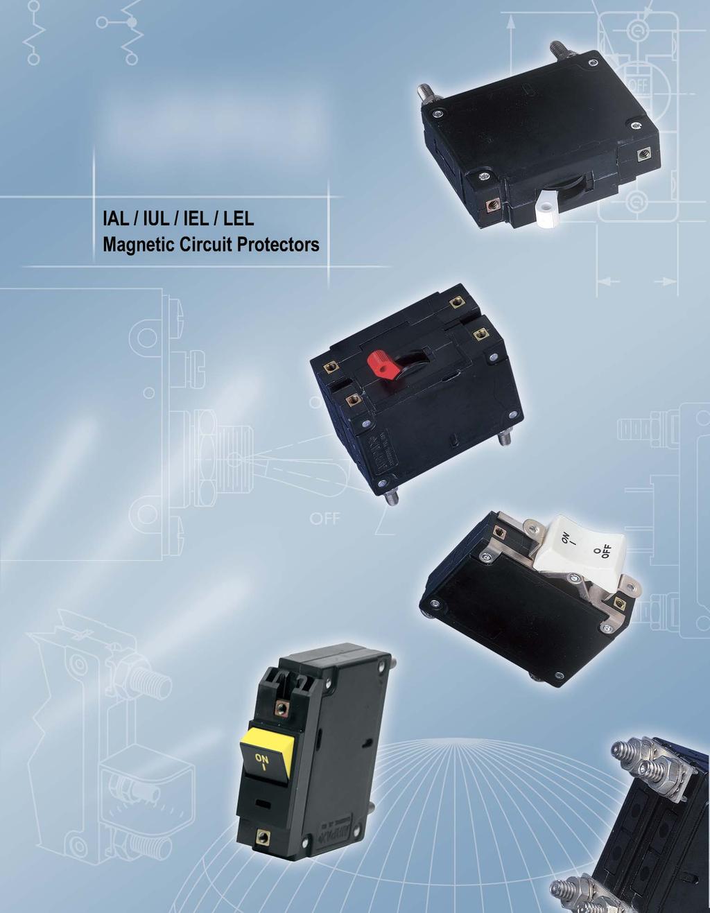
2 Single Pole Circuit Protectors 29 MultiPole Circuit Protectors 3 BX Style Circuit Protectors 3 HighCurrent Magnetic Circuit Protectors 32 Panel Seal Circuit Protectors 33 Rocker Handles 34 Configurations 35 MidTrip and SnapIn ptions 37 Remote perated Circuit Protectors 38 perating Characteristics 39 Delay Curves 4 Specifications 44 IAL/IUL/IEL Decision Tables 46 LEL Decision Tables 48 LELHP Decision Tables 5


3 SINGLE PLE CIRCUIT PRTECTRS magnetic circuit protectors provide lowcost power switching, reliable circuit protection and accurate circuit control for equipment in the international marketplace. IAL models are for those applications where the unit s inherent attributes are desired, but compliance with the various standards is not required. IUL models have been tested and approved in accordance with UL 77 requirements for UL recognition. IEL/LEL models are VDE approved to VDE 66, part. They meet IEC spacing requirements, mandatory for equipment which must comply with IEC specifications 6 and 95, and VDE specifications 84 and 85. In addition, the IEL models are Supplementary Protectors per UL 77 and CSA 22.2 No. 235 and LEL models are UL listed under the conditions of UL489 and CSA 22.2 No. 5.. Both are CCC Approved (IEL is pending). Airpax type circuit protectors are available in a wide variety of configurations, including series, series with auxiliary switch, shunt and relay with choice of delays and ratings in and/or Hz or 4Hz versions. Single or multipole versions are available with a variety of pole arrangements to meet your specifications. Please see the appropriate product specification table for ratings and limitations. 2X SCREW STUD (SEE TABLE).42 [.2] 2.49 [63.24].28 [7.4].94 [49.28].28 [7.3] Single Pole, Standard Stud Terminal.438 [36.53] [9.5].94 [49.28].42 [3.6].42 [3.6] Single Pole Screw Terminal.859 [47.22] 2X 632 THREAD.4 [3.56] DEEP M3 IS THD. PTIAL.22 [5.59] 2.6 [52.32].4 [3.56].94 [49.28].375 [9.53] Note: Each outer terminal is supplied with a flatwasher, tooth lockwasher and a hex nut..69 [7.53] Clip Terminal.28 [7.3] M6 /4 2 M5 32 Screw stud thread.392 [9.96].592 [5.4] Notes: Tolerance ±.5 [.39] unless noted. Dimensions in brackets [ ] are millimeters. A Terminal protrusion dimensions are referenced from back of mounting panel. B Each screw terminal is supplied with a 32x.32 [7.92] or M5 x 8mm screw, flatwasher and external tooth lockwasher. C Stud terminals are supplied with a flatwasher, external tooth lockwasher and a 32 or M5 hex nut (<=7A) (<=5A for LEL), ¼2 or M6 hex nut (>7A)(>5A for LEL)..755 [9.8].448 [36.78].432 [.98].25 [6.35] Dim. A (.45) Mounting Detail 2.6 [52.32] 2X.56 [3.96] Dim. B (.35) Bullet Terminal.967 [24.57] Bullet terminal receptacle should be.32 ±. diameter hole not less than.25 depth. Contact Airpax for other bullet sizes. Single Pole Circuit Protectors 3

4 MULTIPLE CIRCUIT PRTECTRS Multipole protectors are combined in an assembly with the trip mechanisms internally coupled. A fault in any protected circuit opens all poles simultaneously. Applications include use in polyphase circuits, singlephase threewire systems, or in two or more related but electrically isolated circuits. A mix of delays, ratings and configurations are offered. The auxiliary switch is offered with either gold or silver contacts and is available when a series construction pole is specified. Two Pole Protectors An assembly consisting of two single pole units, having their trip mechanisms internally coupled, is available with either a single toggle handle or with a handle per pole. Please see decision one of the part number decision tables. Individual poles may vary in ratings, delays and internal configurations. If the poles are of series construction, an auxiliary switch may be included in either or both poles, allowing you to mix SELV and hazardous voltages. Two Pole IELH IEL.28 [7.4] (SEE TABLE).4 (SEE TABLE) [3.56].42 [.2].22 [5.59] 4X 632 THREAD.4 [3.56] DEEP M3 IS THD. PTIAL.94 [49.28].438 [36.53].42 [3.6] 2.6 [52.32].859 [47.22].69 [7.53] 2.49 [63.24].55 [38.48].55 [38.48] Note: Tolerance ±.5 [.38] unless noted. Dimensions in brackets [ ] are millimeters. Two Pole* Two Pole* M6 / X.56 [3.96].53 [38.86] M Screw stud thread.545 Dim. A (.45).687 Dim. B (.35).448 [36.78] 2.6 [52.32] Note: Each outer terminal is supplied with a flatwasher, tooth lockwasher and a hex nut..432 [.97] Note: A Terminal protrusion dimensions are referenced from back of mounting panel. B Each screw terminal is supplied with a 32x.32[7.92] or M5 x 8mm screw, flatwasher and external tooth lockwasher. C Stud terminals are supplied with a flatwasher, external tooth lockwasher and a 32 or M5 hex nut (<=7A), ¼ 2 or M6 hex nut (>7A). [9.5] [9.5] Panel Mounting Detail Tolerance ±.5 [.3] unless noted. 32 MultiPole Circuit Protectors

5 BX STYLECIRCUIT PRTECTRS Three Pole and Four Pole Protectors The three pole structure consists of three single pole units assembled with an internal mechanical interlock which actuates all units simultaneously. The units are available with either a single toggle handle or with a handle per pole. Units with four pole construction operate with a minimum of two center toggle handles or with a handle per pole. Please see decision one of the part number decision tables. Mixing of delays, ratings and configurations is available in each individual pole. The auxiliary switch is offered in any series trip pole. Protector poles are numbered consecutively when viewed from the terminal side, with the position up, starting with pole # on the left side and proceeding to the right. BX Style Circuit Protectors The innovative new design of our BX Style circuit protectors features a flat rocker that will satisfy your aesthetic needs while guarding against accidental actuation, providing the highest degree of circuit protection and quality. nly Airpax offers this new standard in user interface. Available on a variety of versions with a full range of agency approvals, the IEL BX style circuit protectors meet or exceed all current performance specifications, including interrupting capacities up to 5, amperes. Three Pole IEL Mounting Detail* [57.53] Three Pole IELH [9.5] [9.5] Mounting Detail* 2.73 [55.9].859 [47.22].387 REF. [9.84].25 [3.7].768 [9.49] 2.49 [63.25].395 [35.43] [57.53] [9.5] 2.28 [57.9] [9.5].239 [3.47].34 [7.98] Four Pole IEL Mounting Detail*.53 [38.86] 632 THD. MUNTING M3 IS THD. PTIAL [9.5] [9.5] Four Pole IELH 3.5 [76.58] [9.5] [9.5] [9.5] Mounting Detail* 3.3 [76.96] PTIAL GUARD (SEE DETAIL C ) SINGLE PLE.66 [42.6].66 [42.6] 2X Ø.56 [3.96].2 [5.8].26 [32.] Panel Mounting Detail Mounting Detail Tolerance: ±.5 [.3] unless noted 3.5 [76.58] [9.5] [9.5] [9.5] Note: Tolerance ±.5 [.39] unless noted. Dimensions in brackets [ ] are millimeters. *See Single Pole Mounting Detail for Hole Sizes and Locations. BX Style Circuit Protectors 33

6 LELHP/CELHP MAGNETIC CIRCUIT BREAKERS The Airpax LELHP/CELHP high current magnetic circuit breaker compliments our entire series of LEL circuit breakers. Its unique, parallel current sensing design provides precise current overload protection and reliability in the compact size of a two pole LEL. The unit is ideal for high power applications such as drive motor systems and telecommunication power systems. It is available in series and series with auxiliary switch configurations with a choice of delays for ratings of 25, 5, 75 and 2 amperes. The LELHP is UL listed under the conditions of UL489 and CSA certified. The CELHP is UL listed under the conditions of UL489A. Midtrip handle indication, voltage trip and remote operator options complete the LELHP/CELHP circuit breaker series. Please see the individual product tables for approved ratings. Contact Airpax for specific part number. Two Pole.28 [7.4].687 [7.45].545 [3.84].4 [3.56].55 MAX [38.48].74 [8.8] (Note E).42 [.2] 2X 632 THREAD.4 [3.56] DEEP M3 IS THD PTIAL.22 [5.59].94 [49.28].47 [26.59].282 [32.56].64 [6.26] 2.49 [63.25].438 [36.53] 2.6 [52.32] /42 STUD (M6 x. STUD PTI).859 [47.22].69 [7.53] [9.5] 34 Series Parallel REC4. [2.79] MAX [6.93] (SEE NTE ).26 [6.6] LELHP/CELHP Magnetic Circuit Breakers Series Parallel with optional REC4 Auxiliary switch C N NC BREAKER IN PSITI 75/2 Parallel Pole Three Pole (Note D).74 [8.8] (Note E).74 [8.8] (Note E) 2.49 [63.25].42 [.2].438 [36.53] 2.6 [52.32] [57.53] 6X 632 THREAD.4 [3.56] DEEP M3 IS THD PTIAL Notes: Tolerance ±.5 [.39] unless noted. Dimensions in brackets [ ] are millimeters. A Terminal protrusion dimensions are referenced from back of mounting panel. B Each screw terminal is supplied with a 32x.32[7.92] or M5 x 8mm screw, flatwasher and external tooth lockwasher. C Stud terminals are supplied with a flatwasher, external tooth lockwasher and a 32 or M5 hex nut (<=7A), /4 2 or M6 hex nut (>7A). D Units are supplied without bus bars must have a minimum copper strap (3/32 x /2 x /6 ) of appropriate length to accommodate connections tying each set of terminals together. E ther spacing available upon request. Contact factory for assistance..22 [5.59]

7 IALN/IULN PANEL SEAL CIRCUIT PRTECTRS The laln/iuln family is a sealed toggle version of the IAL/IUL family. The silicone rubber seal around the handle assures panel seal integrity and makes this style a natural for harsh environments. This sealed toggle family is available in one to three pole models with ratings of.5 to 5 amperes. Above 5 amperes consult factory..3 [3.3] 632 MTG. SCREW FR HIGH SHCK MTG. LCKWASHER /232 HEX NUT.42 [3.6] 2.4 [5.82].625 [5.88] [9.5] Single Pole Two Pole Three Pole KEYWAY.6 [.52].65 [.65] WIDE.3 [.76].35 [.89] DEEP [9.5].55 [38.48] [57.53].375 [34.92] 2.49 [63.25].656 [6.66] (ptional handle may be in pole 2 instead of pole.) Panel Mounting Details: Tolerance ±.5 [.3] Unless noted. Single Pole Two Pole* Three Pole*.656 [6.66].56 [3.96].55 [3.8] [9.5] [9.5] [9.5] ptional handle *See Single Pole Mounting Detail for Hole Sizes and Locations. Notes: A Terminal protrusion dimensions are referenced from back of mounting panel. B Each screw terminal is supplied with a 32x.32[7.92] or M5 x 8mm screw, flatwasher and external tooth lockwasher. C Stud terminals are supplied with a flatwasher, external tooth lockwasher and a 32 or M5 hex nut (<=7A), ¼ 2 or M6 hex nut (>7A). IALN / IULN Panel Seal Circuit Protectors 35
8 RCKER HANDLE STYLES IALX/IULX/IELX Rocker Handle Styles The rocker style is available in one to four poles. Choose either vertical or horizontal mounting with, international markings or a combination of both. Available.5 to 5 amperes. Above 5 amperes consult factory. Five front panel enhancing colors including black, white, red, grey and orange are available [63.25].94 [49.28].859 [47.22].375 [34.92] [3.6] [57.2].49 [.65] Single Pole 2X 632 THD. (TYP.) M3 IS THD. PTIAL Two Pole Three Pole Four Pole Panel Mounting Detail* Single,Two & Three Pole Four Pole** [9.5].5 [38.35].972 [5.9].66 [42.6] [32.].66 [42.7].26 [32.] [9.5].735 [8.67] (HANDLE WIDTH).499 [38.7] (ptional handle may be in Pole 2 instead of Pole.) [57.2] 3.5 [76.58].2 [5.8] 2X.56 [3.96] [9.5] *Mounting detail tolerance ±.5 [.3] Unless noted. **See single mounting detail for hole sizes and locations. Note: A Terminal protrusion dimensions are referenced from back of mounting panel. B Each screw terminal is supplied with a 32x.32[7.92] or M5 x 8mm screw, flatwasher and external tooth lockwasher. C Stud terminals are supplied with a flatwasher, external tooth lock washer and a 32 or M5 hex nut (<=7A), ¼2 or M6 hex nut (>7A). IALZX/IULZX/IELZX Rocker Handle Styles The IALZX/IULZX/IELZX style adds our rocker handle options of contrasting dual color rocker actuators, affording a clear visual indication of the handle position and integrated handle guards, to help prevent accidental turnon and turnoff of the unit. Available with a black rocker and white, red or green indicator color for either or indication [63.25] 2.73 [55.9].859 [47.22].34 [7.98].42 REF [.67].2 [5.].772 [9.62].395 [35.43].239 [3.47].56 [2.85] PTIAL HANDLE GUARDS [9.5].66 [42.6] 2X 632 THD. M3 IS THD. PTIAL Panel Mounting Detail Mounting Detail Tolerance: ±.5 [.3] Unless Noted..66 [42.7] 2X.56 [3.96].2 [5.8] [9.5].26 [32.] Note: Tolerance ±.5 [.38] unless noted. Dimensions in brackets [ ] are millimeters. 36 Rocker Handle Styles

9 IAL/IUL/IEL CFIGURATIS Series Trip The most popular configuration for magnetic protectors is the series trip where the sensing coil and contacts are in series with the load being protected. The handle position conveniently indicates circuit status. In addition to providing conventional overcurrent protection, it s simultaneously used as an onoff switch. Series and Switch nly.28 Dimension B [7.3] (See Table).94 [49.28] SERIES SWITCH LY Shunt Trip The shunt trip is designed for controlling two separate loads with one assembly. The control is established by providing overload protection for the critical load. When the current through this load becomes excessive and reaches the trip point, the protector will open and remove power from both loads simultaneously. The total current rating of both loads must not exceed the maximum contact rating. Dual Coil By combining two electrically independent coils on a common magnetic circuit, it is possible to provide contact opening when either an overcurrent or trip voltage is applied to the respective coils. ne coil will be a current trip coil with standard specifications. The second, or dual coil, can be used to provide a control function permitting contact opening from a remote interlock or other transducer functions. Standard coils are 6, 2, 24, 48, 2 and 24 volts. Tripping is instantaneous and must be removed (usually selfinterrupting) after trip. Auxiliary Switch (Applies to Series Trip nly) This is furnished as an integral part of a series pole in single or multipole assemblies. Isolated electrically from the protector s circuit, the switch works in unison with the power contacts and provides indication at a remote location of the protector s onoff status. Auxiliary switch contacts actuate simultaneously with the main protector contacts, and will open regardless of whether the protector contacts are opened manually or electrically. For auxiliary switch ratings below 6Vac or 5Vdc, an auxiliary switch with gold contacts, designated as REG is available. Gold contacts are not recommended for load current above milliamps..29 [32.77].94 [49.28] Dimension A (See Table) Series with Auxiliary Switch.278 [7.5].55 [26.8].33 [33.78].795 [2.9].648 [6.46] M6 /4 2 M5 32 Screw stud thread [6.76].4] Dimension B (See Table) 2.64 [67.6] (SEE NTE A) C N NC Dim. A (.45) BREAKER IN PSITI Dim. B (.35) Note: Each outer terminal is supplied with a flatwasher, tooth lockwasher and a hex nut. Shunt and Dual Coil Note: A Terminal protrusion dimensions are referenced from back of mounting panel. B Each screw terminal is supplied with a 32x.32[7.92] or M5 x 8mm screw, flatwasher and external tooth lockwasher. C Stud terminals are supplied with a flatwasher, external tooth lock washer and a 32 or M5 hex nut (<=7A), ¼2 or M6 hex nut (>7A). Spacing for VDE Switch.266 [32.6] [7.7] [24.66] SHUNT DUAL CIL [64.52] [4.75] (SEE NTE A).25 [6.35] IREC [64.52] [2.79] (SEE NTE A).26 [6.6] IREC4, IREG4 IAL/IUL/IEL Configurations 37
10 IAL/IUL/IEL CFIGURATIS (CT D) Relay Trip This permits the overload sensing coil to be placed in a circuit which is electrically isolated from the trip contacts. The coil may be actuated by sensors monitoring pressure, flow, temperature, speed, etc. ther typical applications include crowbar, interlock and emergency/rapid shutdown circuitry. Trip may be accomplished by voltage or current, which must be removed after trip. Barriers FIG. FIG.2 Voltage Trip Sometimes called dump circuits or panic trip circuits, these units make it possible to open main power contacts with lower power inputs from one or more sources. This configuration is becoming increasingly more important for sensitive circuitry and denser packaging in automation systems. Available in series, shunt or relay configurations..67 [7.2] 2.74 [69.6].98 [27.89].22 [3.].378 [35.] [7.69] [24.8] 3. [78.74] Relay and Dual Coil.795 [2.9] [6.76.4].28 [7.4] FIG.3 FIG.4.94 [49.28].33 [33.78].722 [8.34].72 [8.3].47 [29.3].33 [.84].72 [8.3].47 [29.3].33 [.84] 2.64 MAX 2.56 [65.2] 2.56 [65.2] RELAY DUAL CIL NTE: THIS BARRIER CAN BE FLIPPED T CVER EITHER PLE. Notes: Tolerance ±.5 [.39] unless noted. Dimensions in brackets [ ] are millimeters. A Terminal protrusion dimensions are referenced from back of mounting panel. B Each screw terminal is supplied with a 32x.32[7.92] or M5 x 8mm screw, flatwasher and external tooth lockwasher. C Stud terminals are supplied with a flatwasher, external tooth lockwasher and a32 or M5 hex nut (<=7A), ¼2 or M6 hex nut (>7A). Rating ption IEL 24/45Vac 45V (VDE) 277/48Vac /42, M6 studs for AC 2/24Vac multipole Standard Barrier Fig. Fig. 2 ptional Barrier Fig. 2,3 & 4 Fig. 3 & 4 25Vdc LEL All multipole Hz Fig. 2 Fig. 3 & 4 All multipole 8Vdc if opposite polarity Fig. 2 Fig. 3 & 4 25Vdc Fig. 2 Fig. 3 & 4 38 IAL/IUL/IEL Configurations Note: ptional barrier available with factory assigned part number. Contact factory for assistance.

11 MIDTRIP INDICATI / SNAPIN MUNTING PTIS MidTrip Indication Circuit protection, rapid fault location and alarm capability are blended together in the Airpax midtrip indication option. This option is designed for automatic handle movement to a middle position upon electrical overload, allowing for easier detection of the fault circuit and minimizing downtime due to the overload condition. In the optional auxiliary switch configuration, the switch allows an alarm or signal to be forwarded when the protector trips and the handle moves to the middle position. The alarm can be disengaged by the manual actuation of the handle to the position. nce the fault has been corrected, the circuit protector can be reset to the position. The midtrip option is available in one, two or three pole toggle handle packages and in either standard panel screw or snapin mounting. Please see specification tables of specific product for available ratings. 2.6 [52.35] PSITI MIDTRIP PSITI PSITI 3.22 [8.79] MidTrip Handle Positions C N NC BREAKER IN R MANUALLY TURNED PSITI C N NC BREAKER IN MIDTRIP PSITI (ELECTRICALLY TRIPPED).995 [25.27] [44.45] [ ] Panel Mounting Detail DIM.A (SEE TABLE) [63.37] SnapIn Mounting The snapin mounting adapter allows for simplified mounting of most IEL/LEL toggle handle products. Prior to shipment, the adapter is attached to the circuit protector during our final product assembly, allowing you to securely snap the unit into a rectangular panel cutout. This eliminates the need for panel mounting hardware and associated assembly costs. Available for units up to three poles, with or without an option handle guard..687 [7.45].56 [39.62] Panel Mounting ptions Number of Poles Dimension A Panel Thickness [.57+.3] pole 2 pole 3 pole Note: Tolerance ±.5 [.39] unless noted. Dimensions in brackets [ ] are millimeters. MidTrip Indication/SnapIn Mounting ptions 39
12 RCB REMTEPERATED CIRCUIT PRTECTR The Airpax Remote perated Circuit (RCB) provides the convenience of remote power disconnect and reset capability with the safety and accuracy of a magnetic current sensing device. It allows the operation of the circuit protector from various locations in the system, facility or site, while not sacrificing the ability to manually operate the protector if required. Service, diagnostics, load shedding and power distribution control functions can now be performed in areas that were previously unattended, inaccessible or unsafe. Based on our popular IEL/LEL circuit protector series, the RCB shares the same dimensional characteristics (maximum three poles plus the remote operator) for easy adaptation into existing panel designs, yet its compact size allows efficient use of space for new design applications. In addition, the RCB has been designed to meet the requirements of domestic and international agency standards for motor operated circuit protection, ensuring worldwide component acceptance. Contact Airpax for specific part number. REMTE PERATR CNECTR PLUG A CNECTR PLE PLE 2 Note: Stud terminal style shown..94 [49.28].28 [7.4].42 [3.6].859 [47.22].4 [3.56].69 [7.53] Single Pole Two Pole Three Pole.42 4X 632 THREAD [.2].22 [5.59].4 [3.56] DEEP M3 IS THD. PTIAL PLE 4 PLE 3 PLE 2 PLE 2.49 [63.24].438 [36.53] 2.6 [52.32] REMTE PERATED SEVERE ELECTRIC SHCK HAZARD W A R N I N G WER EA KER BEFRE CTACT WITH LAD. REMTE PERATED SEVERE ELECTRIC SHCK HAZARD W A R N I N G WER EA KER BEFRE CTACT W ITH LAD. REMTE PERATED SEVERE ELECTRIC SHCK HAZARD W A R N I N G WER EA KER BEFRE CTACT WITH LAD. 4X.56 [3.96].55 [38.48] Panel Mounting Details Single Pole.53 [38.86] Two Pole* [57.53] 3.5 [76.58] Three Pole* 3.3 [76.96].448 [36.78] 2.6 [52.32].432 [.97] [9.5] Remote perator Module Specifications Continuous Input Voltage: 8 Vdc Max., 2 Vdc Min. Input Ripple Range: 2 Vdc peak to 8 Vdc peak Maximum Current: Startup:. A, Running:.3 A Transit Time: Less than 2 seconds Endurance: 4, operations min. Dielectric Strength:,5 Vac between connector pins and grounded metal. Caution should be taken during dielectric testing. High voltage should not be applied between connector pins. [9.5] 2.28 [57.9] [9.5] *See single pole mounting detail for hole sizes and locations. [9.5] [9.5] Panel Mounting Detail: Tolerance ±.5 [.3] Unless noted. [9.5] 4 RCB Remote perated Circuit Protector Note: Use Amp connector part numbers 7267 (housing), and 77988/7639 (pins). Not supplied.
13 PERATING CHARACTERISTICS Typical Protector Resistance/Impedance Current ratings in amperes Resistance hms 5, 52, 53, 59 Hz Impedance hms 4Hz* Impedance hms 6, 62, 63, 69 4, 42, 43, ** ** **.55 2.**.55 Notes: R and Impedance based on % rated current applied and stabilized for a minimum of one hour. Tolerance.52.5 amperes 2%; amperes 25%; 22 amperes 5%. Consult factory for special values and for coil impedance of delays not shown. Percentage verload vs Trip Time in Seconds Delay % 25% 5% 2% 4% 6% 8% % 4* No trip May trip * No trip May trip * No trip May trip * No trip May trip. max..5 max..2 max..2 max..2 max..2 max. 5 No trip *** No trip No trip No trip No trip No trip max max max max max max max No trip No trip.2 max. max..5 max..22 max..7 max..7 max..7 max * Available only in IAL/IUL/IEL; not available in LEL. ** LELHP current ratings, only. *** Not available in LELHP. perating Characteristics 4
14 IEL/IUL/IAL/LEL DELAY CURVES 4Hz,, Hz Delay Curves (typ) A choice of delays is offered for, Hz, 4Hz, or combined /Hz applications. Delays 49, 59, 69 and 79 provide fastacting, instantaneous tripping and are often used to protect sensitive electronic equipment (not recommended where a known inrush exists). Delays 4, 5, 6 and 7 have a short delay for general purpose applications. Delays 42, 52, 62 and 72 are long enough for most transformers and capacitor loads. Delays 43, 53, 63 and 73 are extra long for special motor applications. Inrush Pulse Tolerance The table on page 39 provides a comparison of inrush pulse tolerance with and without the inertia delay feature for each of the Hz delays. Pulse tolerance is defined as a single pulse of half sine wave peak current amplitude of 8 milliseconds duration that will not trip the circuit protector. The table below provides a guide to determine if the inertia delay feature is required. Consult factory for further assistance. Delay Pulse Tolerance 6, 62, 63 (. amp.) 2 times (approx.) rated current 6F, 62F, 63F (.25 amp.) 2 times rated current 6F, 62F, 63F (25. amp.) 8 times rated current DELAY 6 DELAY 62 TIME IN SECDS TIME IN SECDS PERCENT F RATED CURRENT PERCENT F RATED CURRENT 8 DELAY 63 DELAY 69 TIME IN SECDS. TIME IN SECDS PERCENT F RATED CURRENT PERCENT F RATED CURRENT 8 42 IEL/IUL/IAL/LEL Delay Curves
15 DELAY CURVES Delay Curves (typ) DELAY 5 DELAY 53 TIME IN SECDS TIME IN SECDS PERCENT F RATED CURRENT 25 PERCENT F RATED CURRENT TIME IN SECDS. DELAY 52 TIME IN SECDS. DELAY PERCENT F RATED CURRENT PERCENT F RATED CURRENT 8 Delay Curves 43

16 IAL/IUL/IEL DELAY CURVES 4Hz Delay Curves (typ) *Available only in IAL/IUL/IEL; not available in LEL. DELAY 4 DELAY 43 TIME IN SECDS TIME IN SECDS PERCENT F RATED CURRENT 25 PERCENT F RATED CURRENT DELAY 42 DELAY 49 TIME IN SECDS. TIME IN SECDS PERCENT F RATED CURRENT PERCENT F RATED CURRENT 8 44 IAL/IUL/IEL Delay Curves

17 IAL/IUL/IEL DELAY CURVES /Hz Dualfrequency Delay Curves (typ) TIME IN SECDS DELAY PERCENT F RATED CURRENT DELAY 73 TIME IN SECDS DELAY PERCENT F RATED CURRENT DELAY 79 TIME IN SECDS. TIME IN SECDS PERCENT F RATED CURRENT PERCENT F RATED CURRENT 8 IAL/IUL/IEL Delay Curves 45
18 IAL/IUL/IEL/IDL/LEL SPECIFICATIS Trip Free Will trip open on overload even when forcibly held in the position. This prevents the operator from damaging the circuit by holding the protector on. Trip Indication The operating handle moves positively to the or midtrip position on electrical overload. Ambient peration IAL/IUL/IEL protectors operate in temperatures between 4 C to +85 C. Insulation Resistance Not less than megohms at 5 volts. Dielectric Strength IAL/IUL/IEL protectors withstand 375Vac (25Vac for LEL), 6Hz for 6 seconds between all electrically isolated terminals except auxiliary switch terminals shall withstand 6Vac, 6Hz for REG and REC types. Four terminal dual coil and relay construction (not offered in the LEL) will withstand 5Vac. Endurance perating as a switch, the operating life exceeds, operations, 6 at rated load, 4 without load, at a rate of 6 per minute. Electrical Characteristics.5 amperes 8Vdc, 24Vac Max., 24/45Vac at 5 amperes Max., Hz and 4Hz. Consult factory for specific product ratings. Units rated for 24/45Vac and above 5 amperes are not suitable for acrosstheline motor starting. Poles ne through six poles available. Construction Series, shunt, relay dual coil and series with auxiliary switch available in various delays and combinations. Auxiliary Switch When supplied shall be S.P.D.T. configuration. Non VDE approved switches have a maximum UL rating of. amperes, 25 volts, 6Hz; 3. amperes, 5 volts (REC type) or. amperes, 25 volts, 6Hz (REG type). VDE approved switches have a maximum UL rating of. amperes, 25 volts, 6Hz (REC type); or. amperes, 25 volts, 6Hz (REG; type). The maximum VDE ratings are. amperes, 25 volts, 6Hz (REC type);. amperes, 25 volts, 6Hz (REG type). Moisture Resistance Meet all the requirements of MILPRF55629 when tested in accordance with Method 6 of MILSTD22. Salt Spray (Corrosion) Meet the requirements of MILPRF55629 when tested in accordance with Method of MILSTD22. Shock Circuit protectors shall not trip when tested per MILSTD22, Method 23, Test Condition I with % rated current applied to delayed units and 8% rated current to instantaneous units. Vibration Circuit protectors shall not trip when vibrated per MILSTD22, Method 24, Test Condition A with % rated current applied to delayed units and 8% rated current to instantaneous units. UL5 (Marine Ignition Protected) The IDL/IDLH is approved for Marine Ignition Protection (series configuration only), covering ignition protected circuit protectors. This specification requires devices to be used in accordance with the requirementsof U.S. Coast Guard and Fire Protection Standard for Pleasure and Commercial Motor Craft, ANSI/MFPA #32. Recommended Torque Specifications Approximate Weight Per Pole 632 mounting inserts M3 mounting inserts 32 screw terminals M5 screw terminals 32 stud terminals M5 stud terminals 4 2 stud terminals 6 8 inch pounds 4 5 inch pounds 4 5 inch pounds 4 5 inch pounds 3 4 inch pounds 3 4 inch pounds 4 45 inch pounds unces 3. Grams 9 Note: When applicable, mechanical support must be provided to terminals when applying torque. 46 Specifications
19 IAL/IUL/IEL/IDL/LEL/LELHP SPECIFICATIS Agency Approvals Voltage (V) Rated Current (A) Minimum / Maximum Interrupting Capacity, Amps IAL/IUL/IEL Max Rating (V) * 25 2/24* 24* 24* * 25* 24/45* 24/45** /48 25 LEL/LELHP 4 & 3 & 3 3 & & 3 & 3 3 & 3 Minimum Poles VDE Frequency (Hz) Phase UL/CSA UL77 & CSA VDE () 5 (2) 5 (3) 2 5 () 5 () 2 5 Max Rating (V) Frequency (Hz) Phase Minimum Poles UL/CSA VDE UL489 VDE /24 24 CEL/CELP & 3 & 3 & 3 & 3 2** 3** 2** 3** Max Rating (V) Frequency (Hz) Phase Minimum Poles UL/CSA VDE UL489A VDE IDL/IDLP 2** 2** 3** Max Rating (V) Frequency (Hz) Phase Minimum Poles UL/CSA VDE UL77 & CSA VDE Notes: * Not suitable for motor starting applications **Paralleled Poles () With 25A max. series fuse (2) Series combination with 29 or 229 (3) With 75A max. series fuse & 3 2** Note: A clearance of inch for and 2 inches for AC is required between the arc vent and any conductive surface or components. IAL/IUL/IEL/IDL/LEL/LELHP Specifications 47
20 IAL/IUL/IEL DECISI TABLES How to rder The ordering code for circuit protectors may be determined by following the decision steps in the appropriate part number decision table subsequent to this page. The coding given permits a selfassigning part number but with certain limitations. Special applications may require a factory assigned part number. Typical examples are units with mixed ratings, combinations of styles, or constructions not listed in the third decision table, etc. With these, it is suggested that order entry be by description and/or drawings, and a part number will be established. Additionally, it is standard policy to establish a factoryassigned part number whenever a descriptive drawing exists to provide cross reference, traceability and manufacturing control. When specifying a circuit protector for AC motor start or high inrush applications, the peak amplitude and surge duration should be specified for factory assistance in rating selection. For example the code shown is the code for a single pole protector with a series construction and auxiliary switch, designed for operation in a Hz circuit. It has a short time delay, rating of 2 amperes and a marked black handle, and is VDE approved. To determine the ordering number for your particular IAL/IUL/IEL unit, simply follow the steps shown. You may use this number to place an order or as a reference for further questions you may have. First Decision Select Type and Terminal Type Description IAL ne handle per unit **IUL ***IEL IALH ne handle per pole **IULH ***IELH IALN ***IULN IALX **IULX ***IELX IALZX **IULZX ***IELZX 3 * IDL * IDLH *** IML *** IMLH IALBX **IULBX ***IELBX **IMLBX ne handle per unit panel seal ne handle per unit, rocker, bracket mounting ne handle per unit, rocker, integral mounting ne handle per unit UL 5 ne handle per pole UL 5 ne handle per unit mid trip indication ne handle per pole mid trip indication ne handle per unit, rocker, accidentaloff protection ne handle per unit, mid trip indication, rocker, accidentaloff protection *UL Recognized **UL Recognized, CSA Certified ***UL Recognized, CSA Certified, VDE Approved Third Decision Internal Configuration Switch only Series K C B Terminal Standard screw terminal, no designation required Stud terminals Clip terminals Bullet terminals 2 Second Decision Poles Single pole Two pole Three pole Four pole* *Not available in toggle seal handle type. Consult factory for 5 and 6 pole IEL part number. Example: IEL REC46 2. V SW Fourth Decision Frequency & Delay Switch only 4Hz short delay 4Hz long delay 4Hz motor start 4Hz 5% instant trip 5 7 Notes: IEL, IELH and IELX circuit protectors are designed to meet 8mm creepage clearance requirements for installation Category, Pollution Degree 3, Case A as measured in IEC 664. Intended for use in equipment to comply with IEC 95, 6 and VDE 84 & 85. REC4 REC5 REG4 RS4 RLS4 3 4 Series w/ auxiliary switch *. quick connect Series w/ auxiliary switch *.87 quick connect Series w/ auxiliary switch (gold contacts)*. quick connect Series w/ alarm switch, electrical trip,. Q.C. terminals Series w/ alarm switch, electrical trip,. Q.C. terminals (midtrip only) Shunt Relay (not available in IEL/IELX) * nly one auxiliary switch is normally supplied on two or three pole units. Switch is located in the righthand pole (viewed from terminal end) unless otherwise specified. 5 short delay 52 long delay 53 motor start 59 25% instant trip 6 Hz short delay 62 Hz long delay 63 Hz motor start 69 Hz 25% instant trip 7 /6Hz short delay 72 /6Hz long delay 73 /6Hz motor start 79 /6 Hz 35% instant trip For addition of inertial delay, add an F to any delay numeral. V = VDE and CCC Approved C = CCC Approved This approval requires the addition of a C at the end of the part number. The unit will not be VDE Approved. The shaded areas denote VDE and CCC (if applicable) Approval options. This approval requires the addition of a V at the end of the part number. The V will be added to any part number formed entirely from shaded decisions. If nonshaded areas are selected, the unit will not be VDE or CCC Approved, but other approvals still apply. 48 IAL/IUL/IEL Decision Tables Note: CCC Approval is pending. Note: CCC Approval is pending.
21 5 7 Fifth Decision Rated Current Standard ratings listed. For other ratings, please contact the factory Use three numbers to print required value between.5 amperes minimum and. amperes maximum. The VDE (Ith) will be 95% of the UL/CSA rated current. Seventh Decision Handle Color and Marking Selection IAL, IUL, IEL, IALH, IULH, IELH Toggle Handle Marked* Color Unmarked I 6 A B C D E F G K L M P T U W X 2 Sixth Decision ptional Standard hardware. No designation required. Metric thread mounting inserts and terminals Barrier 277V (Hz only) (See note 3) 24/45V (Hz only) 277V/48V (Hz only) (See note 4) 24V Hz Handle guard, (available in ZX, BX and snapin versions only) /4 2 stud (M6 stud when A option is selected) ( 7A requires K, >7A do not use K) Handle lock Handle in opposite pole Snapin face plate adapter 8V 2/24V Hz Wire clamp supplied (VDE approved up to and including 6. amps) Handle guard with no actuation feature (BX rocker only) Silver 5/6" (.32") bullet Gold 5/6" (.32") bullet INDICATI Mounting/Indicator Code: A, B, C LAD LAD LAD LAD FIG. 2 FIG. 3 FIG. 4 FIG. 5 FIG. FIG. 6 MARKING DETAIL A (SEE TABLE) I RCKER HANDLE CLR INDICATING CLR FIG. 2 FIG. 3 FIG. 4 FIG. 5 FIG. FIG. 6 INDICATI Mounting/Indicator Code: F, G, H LAD MARKING DETAIL B (SEE TABLE) I INDICATI Mounting/Indicator Code: J, K, L INDICATING CLR RCKER HANDLE CLR LAD LAD LAD I INDICATING CLR RCKER HANDLE CLR Yellow Blue 2 3 (STD) 2 3 Notes:. ne or more descriptions may be used as required. 2. When this is not used, table one may be substituted and U.S. thread and two lockwashers will be supplied. Unit will be rated at 25V (Hz only.) 3. VDE approved at 25Vac 4. VDE approved at 45Vac INDICATI Mounting/Indicator Code: M, N, P, R HANDLE PSITI WITH GUARD N ACTUATI ACCESS PTIAL HANDLE PSITI WITH GUARD Green 4 4 LAD LAD range 6 6 FIG. 2 FIG. 3 FIG. 6 MARKING DETAIL C (SEE TABLE) Seventh Decision Rocker Handle Color, Indicator Color and Marking Selection (See Notes) IALX, IULX, IELX, IALZX, IULZX, IELZX Rocker Handle (Single Rocker Color) Vertical Mounting Horizontal Mounting Rocker Handle Color Indicating Color Marking Color Indicates: Unmarked nff Fig. I Fig.2 nff I Fig.3 nff Fig.4 I Fig.5 nff I Fig.6 Marking Detail Grey range A IALZX, IULZX, IELZX Rocker Handle (Dual Rocker Color) Green Green Green n n n ff ff ff n n n A B C F G H J K L A B C F G H J K L A2 B2 C2 F2 G2 H2 J2 K2 L2 A3 B3 C3 F3 G3 H3 J3 K3 L3 A4 B4 C4 F4 G4 H4 J4 K4 L4 A5 B5 C5 F5 G5 H5 J5 K5 L5 A6 B6 C6 F6 G6 H6 J6 K6 L6 A B IALBX, IULBX, IELBX, LELBX Rocker Handle (Dual Rocker Color) ff M M2 M3 M6 Green Green ff ff N P N2 P2 N3 P3 N6 P6 C Yellow Yellow ff R R2 R3 R6 Notes: A. Bezels of IALBX, IULBX, IELB, IELBX are black. B. Consult factory for other marking options. 49
22 LEL DECISI TABLES LEL LELH LML LMLH LELZX First Decision Select Type and Terminal Type Description LMLZX LELBX LMLBX ne handle per unit ne handle per pole ne handle per unit, midtrip indication ne handle per pole, midtrip indication ne handle per unit, rocker, integral mounting ne handle per unit, rocker, midtrip indication, integral mounting ne handle per unit, rocker, accidentaloff protected ne handle per unit, rocker, midtrip indication, accidentaloff protected Note: ther options available, consult factory. 2 Second Decision Poles Single pole Two pole Three pole K C B Example: LEL REC V * 59 6 Terminal Standard screw terminal, no designation required Stud terminals Clip terminals Bullet terminals Fourth Decision Frequency and Delay short delay long delay motor start 25% instant trip Hz short delay Fifth Decision Rated Current Use three numbers to print. Required value between.5 amps minimum and amps maximum. 6 A B F G K L M P U V X 2 Sixth Decision ptional Metric thread mounting inserts and terminals Barrier 24V Hz Handle guard, (available in ZX, BX and snapin versions only) /4 2 Stud (M6 Stud when A option is selected) ( 5A requires K, >5A do not use K) Handle Lock Handle in opposite pole Snapin mounting plate adapter 2/24Vac, 5 A.I.C., 7A max. 2 pole only with barrier 25V Handle guard with no actuate "off" feature (see detail C) Silver 5/6" (.32") bullet Gold 5/6" (.32") bullet Hz long delay Hz motor start Hz 25% instant trip Notes:. ne or more descriptions may be used as required. 2. When this decision is not used, decision 7 may be substituted and U.S. thread will be supplied. 3. If (M5 or M6) studs are required, use A only on an LELK. 3 Third Decision Internal Configuration For addition of inertial delay, add an F to any delay numeral. *Not available above amps. REC4 REC5 REG4 RS4 RLS4 * Used only with midtrip. Series Series with auxiliary switch. quick connect Series with auxiliary switch.87 quick connect Series with auxiliary switch (gold contacts). quick connect Series with alarm switch, electrical trip,. quick connect Series with alarm switch, electrical trip,. quick connect* V = VDE and CCC Approved The shaded areas denote VDE and CCC (if applicable) Approval options. This approval requires the addition of a V at the end of the part number. The V will be added to any part number formed entirely from shaded decisions. If nonshaded areas are selected, the unit will not be VDE or CCC Approved, but other approvals still apply. C = CCC Approved The approval requires the addition of a C at the end of the part number. The unit will not be VDE Approved. 7 Seventh Decision LEL Toggle Handle Color Selection w/ white markings Yellow w/ black markings 2 w/ white markings 3 Blue w/ white markings 4 Green w/ white markings 6 range w/ black markings 9 w/ black markings See alternate 7th Decision on page 5 for ZX and BX Rocker Handles. Notes: The LEL family of circuit breakers are designed to meet 8mm creepage and clearance requirements for installation Category, pollution degree 3, Case A as measured in IEC 664. Intended for use in equipment designed to comply with IEC 38, 435, 6 AND VDE 73, 84 & LEL Decision Tables
23 7 Seventh Decision Rocker Handle Color, Indicator Color and Marking Selection (See Notes) LELZX & LMLZX Rocker Handle (Single Rocker Color) Vertical Mounting Horizontal Mounting Rocker Handle Color Indicating Color Marking Color Indicates: Unmarked nff Fig. I Fig.2 nff I Fig.3 nff Fig.4 I Fig.5 nff I Fig.6 Marking Detail Grey range A LELZX & LMLZX Rocker Handle (Dual Rocker Color) n A A A2 A3 A4 A5 A6 Green n n ff B C F B C F B2 C2 F2 B3 C3 F3 B4 C4 F4 B5 C5 F5 B6 C6 F6 A ff G G G2 G3 G4 G5 G6 Green ff H H H2 H3 H4 H5 H6 Green n n n J K L J K L J2 K2 L2 J3 K3 L3 J4 K4 L4 J5 K5 L5 J6 K6 L6 B LELBX Rocker Handle (Dual Rocker Color) ff M M2 M3 M6 Green Green ff ff N P N2 P2 N3 P3 N6 P6 C Yellow Yellow ff R R2 R3 R6 Notes: A. Bezels of IALBX, IULBX, IELB, IELBX are black. B. Consult factory for other marking options. I RCKER HANDLE CLR INDICATING CLR I INDICATING CLR RCKER HANDLE CLR I INDICATING CLR RCKER HANDLE CLR INDICATI Mounting/Indicator Code: A, B, C INDICATI Mounting/Indicator Code: F, G, H INDICATI Mounting/Indicator Code: J, K, L INDICATI Mounting/Indicator Code: M, N, P, R HANDLE PSITI WITH GUARD N ACTUATI ACCESS PTIAL HANDLE PSITI WITH GUARD LAD LAD LAD LAD LAD LAD LAD LAD LAD LAD FIG. 2 FIG. 3 FIG. 4 FIG. 5 FIG. FIG. 6 MARKING DETAIL A (SEE TABLE) Area reserved for amperage marking. FIG. 2 FIG. 3 FIG. 4 FIG. 5 FIG. FIG. 6 MARKING DETAIL B (SEE TABLE) FIG. 2 FIG. 3 FIG. 6 MARKING DETAIL C (SEE TABLE) LEL Decision Tables 5
24 LELHP DECISI TABLES 3 Third Decision 5 Fifth Decision Internal Configuration Rated Current (Amps) First Decision Type LELPK* LMLPK* LELZXPK* LMLZXPK* LELBXPK* LMLBXPK* LELHPK* LMLHPK* ne handle per unit ne ZX rocker handle per unit (integral mounting) ne BX rocker handle per unit (integral mounting) accidentaloff protected ne handle per pole * Stud Terminals MidTrip Notes:. ne toggle handle per unit is available on 25 amps to 5 amps units (two parallel pole construction.) amps to 2 amps (three parallel pole construction) require handles in each pole, "H" version First Decision. REC4 REG4 RS4 RLSG4 RLS4 REC5 RS5 RLS5 * Used only with midtrip. Example: Series Series with auxiliary switch. quick connect Series with auxiliary switch (gold contacts). quick connect Series with alarm switch, electrical trip,. quick connect Series with alarm switch, electrical trip, (gold contacts). quick connect* Series with alarm switch, electrical trip,. quick connect* Series with auxiliary switch.87 quick connect Series with alarm switch, electrical trip,.87 quick connect Series with alarm switch, electrical trip,.87 quick connect* 6 A G X P Sixth Decision ptional For other ratings, please consult factory. Metric thread mounting inserts and terminals Handle guard (available in ZX, BX and snapin versions only) Handle guard with no actuate off feature (available in BX versions only) Snapin mounting plate adapter Notes:. ne or more descriptions may be used as required. 2. When this decision is not used, decision 7 may be substituted and U.S. thread will be supplied. LELHPK REC V V = VDE Approved The shaded areas denote VDE Approval options. This approval requires the addition of a V at the end of the part number. The V will be added to any part number formed entirely from shaded decisions. If nonshaded areas are selected, the unit will not be VDE Approved, but other approvals still apply. 2 Second Decision 4 Fourth Decision 7 Seventh Decision Poles Frequency and Delay LELHPK Toggle Handle Color Selection Two pole (up to 5 amps) Three pole (6 to 2 amps) short delay, 25% trip (255 amps) short delay, 35% trip (62 amps) long delay, 25% trip (255 amps) long delay, 35% trip (62 amps) 25% instant trip (255 amps) 35% instant trip (62 amps) w/ white markings Yellow w/ black markings w/ white markings Blue w/ white markings Green w/ white markings range w/ black markings w/ black markings See alternate 7th Decision on page 5 for ZX and BX Rocker Handles. For addition of inertial delay, add an F to any delay numeral. 52 LEL Decision Tables
IAL/IUL/IEL/LEL Series Magnetic Circuit Protectors
 IAL/IUL/IEL/LEL IAL/IUL/IEL/LEL Series Magnetic Circuit Protectors Introduction 29 Single & Multi-Pole 3 Rocker, Sealed Toggle 32 Configurations 36 perating Characteristics 4 Delay Curves 4 Specifications
Single Pole Circuit Protectors 67 Multi-Pole Circuit Protectors 68 Printed Circuit Board Mounting 70 Configurations 72 Operating Characteristics 73
 Single Pole Circuit Protectors 67 Multi-Pole Circuit Protectors 68 Printed Circuit Board Mounting 70 Configurations 72 perating Characteristics 73 Delay Curves 74 Specifications 76 Decision Tables 78 SIGLE
JAE Series. Magnetic Circuit Protectors. Introduction Poles Configurations Operating Characteristics Delay Curves Decision Tables
 JAE Series Magnetic Circuit Protectors Introduction Poles Configurations Operating Characteristics Delay Curves Decision Tables 205 207 211 213 216 217 JAE/JRE/JLE Series Hydraulic Magnetic Circuit Protectors
Single Pole Circuit Breakers 107 Multi-Pole Circuit Breakers 108 IAGX/IUGX/IEGX/CEGX/ IAGZX/IUGZX/IEGZX/CEGZX Breakers 110 IAGBX/IUGBX/IEGBX/CEGBX
 Single Pole Circuit Breakers 07 MultiPole Circuit Breakers 08 IAGX/IUGX/IEGX/CEGX/ IAGZX/IUGZX/IEGZX/CEGZX Breakers 0 IAGBX/IUGBX/IEGBX/CEGBX Breakers IAG/IUG Breakers 2 IEGS/CEGS/IEGHS/CEGHS SnapIn Circuit
209 Series. Magnetic Circuit Protectors
 29 Series Magnetic Circuit Protectors Introduction 249 Power Selector System Multi-Pole Configurations Operating Characteristics Delay Curves Specifications Decision Tables 73 75 77 79 8 82 85 87 29/29/229/249/279
Single Pole Circuit Protectors 55. Multi-Pole Circuit Protectors 56. Configurations 58. Operating Characteristics 59.
 Single Pole Circuit Protectors 55 Multi-Pole Circuit Protectors 56 Configurations 58 Operating Characteristics 59 Delay Curves 60 Specifications 61 Decision Tables 62 SINGLE POLE CIRCUIT PROTECTORS The
209/219/229/249/279 Series Magnetic Circuit Protectors
 29/29/229/249/279 29/29/229/249/279 Series Magnetic Circuit Protectors Introduction 65 249 Power Selector System 67 Multi-Pole 69 Configurations 7 Operating Characteristics 73 Delay Curves 74 Specifications
AP/UP, AP/MIL Series Magnetic Circuit Protectors
 AP/UP, AP/MIL AP/UP, AP/MIL Series Magnetic Circuit Protectors Introduction 68 Single Pole 69 Multi-Pole 70 Configurations 72 Operating Characteristics 73 Delay Curves 74 Specifications 75 Decision Tables
IAL/IUL/IEL/LEL Single Pole Circuit Protectors 139. IAL/IUL/IEL/LEL Multi-Pole Circuit Protectors 140. IAL/IUL/IEL/LEL BX Style Circuit Protectors 141
 Single Pole Circuit Protectors 39 Multi-Pole Circuit Protectors 4 BX Style Circuit Protectors 4 LELHP/CELHP Magnetic Circuit Protectors 42 ALN/ULN Panel Seal Circuit Protectors 43 Rocker Handle Styles
F-Series. Circuit Breaker
 F-Series Circuit Breaker The F-Series hydraulic/magnetic high amperage circuit breakers are designed to handle high current applications in extremely hot and/or cold locations. Due to its timeproven hydraulic/magnetic
F-Series. Circuit Breaker
 F-Series Circuit Breaker The F-Series hydraulic/magnetic high amperage circuit breakers are designed to handle high current applications in extremely hot and/or cold locations. Due to its timeproven hydraulic/magnetic
AP/UP, AP/MIL Series Magnetic Circuit Protectors
 AP/UP, AP/MIL AP/UP, AP/MIL Series Magnetic Circuit Protectors Introduction 77 Single Pole 78 Multi-Pole 79 Configurations 8 Operating Characteristics 82 Delay Curves 83 Specifications 84 Decision Tables
IAX/LUX/LEX Series Low-Depth, Hydraulic-Magnetic Circuit Breakers. Introduction Configurations Delay Curves Operating Characteristics Decision Tables
 IAX/LUX/LEX Series Low-Depth, Hydraulic-Magnetic Circuit Breakers Introduction Configurations Delay Curves Operating Characteristics Decision Tables 23 24 27 28 29 IAX/LUX/LEX Series Low-Depth, Hydraulic-Magnetic
G-Series. Circuit Breaker.
 -Series Circuit Breaker Carling Technologies -Series hydraulic/magnetic circuit breakers offer the highest quality solution to your circuit protection requirements. The -Series is designed to sense over-current
PB-Series. GFCI/ELCI & Panel Seal
 PB-Series GFCI/ELCI & Panel Seal The PB-Series utilizes the hydraulic magnetic principle which provides precise operation and performance even when exposed to extremely hot and/or cold application environments.
CX-Series. Circuit Breaker
 CX-Series Circuit Breaker The CX-Series circuit breaker features a unique and innovative arc-quenching configuration that allows the breaker to safely handle high amperage and high DC voltage applications
PD-Series Ground Fault Circuit Protection
 PD-Series Ground Fault Circuit Protection SmartGuard is an equipment ground fault protection device that functions as a standard high-quality Carling hydraulic/ magnetic circuit breaker, offering customized
These devices meet the requirements of OSHA 29 CFR (b)(1)(ii) and OSHA 29 CFR (a) (2)(ii)(G). Airpax LEL series
(1)(ii) and OSHA 29 CFR (a) (2)(ii)(G). Airpax LEL series") PGFM Series GFCI Ground Fault Protection Sensing Module INTRODUCTION The LineGard PGFM GFCI Sensing Module is a ground fault or equipment leakage sensing device designed and manufactured by North Shore
PGFM Series GFCI Ground Fault Protection Sensing Module INTRODUCTION The LineGard PGFM GFCI Sensing Module is a ground fault or equipment leakage sensing device designed and manufactured by North Shore
Catalog Issued 3-03 (PDF Rev )
") W6/W9 series Magnetic Hydraulic P& Circuit reakers Features Designed for the international market. UL Recognized (UL77 and UL5), CS ccepted and VDE approved. Ratings to 5 amps. Heavy duty #-32 stud connections.
W6/W9 series Magnetic Hydraulic P& Circuit reakers Features Designed for the international market. UL Recognized (UL77 and UL5), CS ccepted and VDE approved. Ratings to 5 amps. Heavy duty #-32 stud connections.
MS-Series. Circuit Breaker
 MS-Series Circuit Breaker Carling Technologies MS-Series Sealed Toggle Circuit Breaker was designed and tested to operate flawlessly in the harshest of environments. Ideally suited for COTS (commercial
ER circuit breaker - Hydraulic magnetic,
 ER circuit breaker - Hydraulic magnetic, Datasheet railway, high current and voltage Features Ideal for high current and high voltage applications Precise, temperature independent operation Panel mount
CR circuit breaker - hydraulic magnetic,
 CR circuit breaker - hydraulic magnetic, Datasheet railway, compact Features Precise, temperature independent operation Panel mount Integrated auxiliary contacts (optional) Up to 6 poles configuration
FR circuit breaker - hydraulic magnetic,
 FR circuit breaker - hydraulic magnetic, Datasheet railway, very high current Features Ideal for very high current applications Precise, temperature independent operation Panel mount Integrated auxiliary
Magnetic Overcurrent Circuit Breaker
 Magnetic Overcurrent Circuit Breaker 808-... Description ngle pole miniaturised magnetic circuit breakers with unique highspeed operating mechanism and push/pull on/off manual actuation. Fitted with electrically
G-Series DIN-RAIL CIRCUIT BREAKER
 G-Series DIN-RAIL CIRCUIT BREAKER The G-Series hydraulic-magnetic circuit breaker insures maximum protection by integrating wiping contacts for longevity; a common trip linkage between poles; a unique
FR circuit breaker - hydraulic magnetic, railway, very high current. Datasheet
 FR circuit breaker - hydraulic magnetic, railway, Datasheet very high current Features Ideal for very high current applications Precise, temperature independent operation Panel mount Integrated auxiliary
AR circuit breaker - Hydraulic magnetic,
 AR circuit breaker - Hydraulic magnetic, Datasheet railway, small Features Description Small hydraulic magnetic circuit breaker for railway applications to protect electronic equipment and components against
Renewable Energy. Circuit Breakers and Disconnects
 Renewable Energy Circuit Breakers and Disconnects HARNESS THE POWER About Carling Technologies Founded in 1920, Carling Technologies is a leading manufacturer of electrical and electronic switches and
Magnetic and Hydraulic-Magnetic Circuit Breaker
 Magnetic and Hydraulic-Magnetic Circuit Breaker 835-... Description Single or multipole hydraulic-magnetic circuit breakers with trip-free - mechanism and toggle actuation. A choice of switching characteristics
Magnetic and Hydraulic-Magnetic Circuit Breaker
 Magnetic and Hydraulic-Magnetic Circuit Breaker 835-... Description Single or multipole hydraulic-magnetic circuit breakers with trip-free - mechanism and toggle actuation. A choice of switching characteristics
Magnetic and Hydraulic-Magnetic Circuit Breaker
 Magnetic and Hydraulic-Magnetic Circuit Breaker 845-... Description Single or multipole hydraulic-magnetic circuit breakers with trip-freemechanism and toggle actuation. A choice of switching characteristics
SNAPAK Series Magnetic Circuit Protectors
 SNAPAK Series Magnetic ircuit Protectors Introduction 61 Handles / Actuators 62 onfigurations 67 perating haracteristics 69 Delay urves & Specs 70 Specifications 71 Hardware 72 Decision Tables 73 T/R/PP/PR
DD Frame - Series Circuit Breakers
 The DD Frame is a compact yet very powerful circuit breaker. Using the hydraulic-magnetic technology which ensures that the breaker performance is unaffected by ambient temperature, the CI DD Frame series
RBR circuit breaker - Remote operated
 - Remote operated Datasheet Features ON-OFF and trip indication Load shedding Energy management Compact size Automatic reset capable Choice of interface styles Panel or 35 mm rail mounting Manual operation
NRA Series. Between main circuit terminals: 2,000V AC, 1 minute Between main circuit and auxiliary contact: 2,000V AC, 1 minute
 RA Series RA Series Key features of the RA series include: Available in 5 different styles Excellent overload and short circuit protection Small size and high-efficiency Life expectancy of over 0,000 operations
H-Series. Circuit Breaker.
 -Series Circuit Breaker The -Series hydraulic/magnetic circuit breaker provides dependable circuit protection in a low cost, compact package. By meeting the IEC spacing requirements, the -Series is the
MDS2 Series. Modular Distribution Systems. Introduction 8-Position Configuration Decision Tables
 MDS2 Series Modular Distribution Systems Introduction 8-Position Configuration Decision Tables 207 208 209 MDS2 Series Modular Distribution Systems INTRODUCTION Sensata Technologies provides circuit-on-demand
GJL 100 A Molded Case Circuit Breaker GJL 75 A Motor Circuit Protector
 GJL 100 A Molded Case Circuit Breaker GJL 75 A Motor Circuit Protector Catalog 0500CT9702R409 2009 Class 525/580 CONTENTS Description............................................. Page General Characteristics...................................
Circuit Breakers Series AM/S
 Heinemann fi Circuit Breakers Series AM/S UL489 LISTED / MEETS INTERNATIONAL STANDARDS Heinemann fi wrote the book on the HYDRAULIC MAGNETIC CIRCUIT BREAKERS by patenting the original technology back in
Section. Circuit Breakers Selection Guide...N-2. NRA Series...N-3. NRBM Series...N-13. NRC Series...
 Section Selection Guide...-2 RA Series...-3 RBM Series...-3 RC Series...-20 General Instructions...-29 Internal Circuit Overview...-29 for more information on this product family visit www.idec.com/circuitbreaker
Electropneumatic Timing Relays Series 7000 Industrial
 DESIGN FEATURES Available in On-Delay, True Off-Delay, and On/Off-Delay. Timing from 0.1 seconds to 60 minutes, fully calibrated in linear increments. Oversize time-calibrated adjustment knobs, serrated
NRBM Series. Between main circuit terminals: 2,000V AC, 1 minute Between main circuit and auxiliary contact: 2,000V AC, 1 minute
 NRBM circuit breakers are the largest in rated current (A to 50A) among the IDEC circuit breakers series. These small sized, high-effi ciency breakers offer a variety of protection characteristics that
1492-CB 1492-GH 1492-GS
 1 The Allen-Bradley Line of Devices Allen-Bradley offers 3 different lines of Circuit Breakers (Supplementary Protectors) and a line of branch circuit rated Fuse Holders. Allen-Bradley Thermal Magnetic
Products :: Circuit Protection :: Thermal Circuit Breakers
 Products :: Circuit Protection :: Thermal Circuit Breakers Thermal Circuit Breaker CLB-Series CLB-Series PDF elibrary The CLB-Series is a compact, single pole, push-to-reset family of thermal circuit breakers
SAR & SAS Circuit Protectors
 SAR & SAS Circuit Protectors 280 QAS, QAL, QFS, QFL Quick-Action Fuses 282 HVS & SARPV Compact Switches for 28 Solar Power Applications SAR & SAS Circuit Protectors Applications: Typical applications include
J-Series CIRCUIT BREAKER
 J-Series CIRCUIT BREAKER Designed to provide high levels of circuit protection, the J-Series is a compact, low profile hydraulic magnetic circuit breaker ideally suited for high power density applications.
Thermal Overcurrent Circuit Breaker 3120-F...
 Thermal Overcurrent Circuit Breaker 20-F... Description An extremely versatile range of rocker switch/thermal circuit breakers (S-type TO CBE to EN 6094 with trip free mechanism) offering the choice of
L-Series. Circuit Breaker
 L-Series Circuit Breaker Carling Technologies is pleased to introduce the new L-Series Circuit Breaker, a compact, high performance breaker ideally suited for the rigors and confined spaces found in today
Thermal Overcurrent Circuit Breaker 3120-F...
 Description An extremely versatile range of rocker switch/thermal circuit breakers (S-type TO CBE to EN 6094 with trip free mechanism) offering the choice of single pole, double pole with single pole protection,
Thermal Overcurrent Circuit Breaker 3120-F...
 Thermal Overcurrent Circuit Breaker 20-F... Description An extremely versatile range of rocker switch/thermal circuit breakers (Stype TO CBE to EN 6094 with trip free mechanism) offering the choice of
Selection Guide. Control Circuit and Load Protection
 Selection Guide Control Circuit and Load Protection Circuit Protection Portfolio 1489-M Circuit Breakers Approved for branch circuit protection in the United States and Canada, and certified as Miniature
Thermal Overcurrent Circuit Breaker 3120-F...
 Thermal Overcurrent Circuit Breaker 0-F... Description An extremely versatile range of rocker switch/thermal circuit breakers (S-type TO CBE to EN 6094 with trip free mechanism) offering the choice of
Thermal Overcurrent Circuit Breaker 3120-F...
 Thermal Overcurrent Circuit Breaker -F... Description An extremely versatile range of rocker switch/thermal circuit breakers (S-type TO CBE to EN 694 with trip free mechanism) offering the choice of single
NRA Series. Between main circuit terminals: 2,000V AC, 1 minute Between main circuit and auxiliary contact: 2,000V AC, 1 minute
 RA Series RA Series RAS RA Key features of the RA series include: Available in 4 different styles Excellent overload and short circuit protection Small size and high-efficiency Life expectancy of over
Thermal Overcurrent Circuit Breaker 3120-F...
 Thermal Overcurrent Circuit Breaker 20-F... Description An extremely versatile range of rocker switch/thermal circuit breakers (Stype TO CBE to EN 6094 with trip free mechanism) offering the choice of
24.4. Miniature Circuit Breakers and Supplementary Protectors. For Immediate Delivery or Tech Support call KMParts.com at (866)
") .4 Miniature Circuit Breakers and Supplementary Protectors SPHM Supplementary Protector SPHM Supplementary Protector Product Description The SPHM Supplementary Protector is a dual rated product for both
.4 Miniature Circuit Breakers and Supplementary Protectors SPHM Supplementary Protector SPHM Supplementary Protector Product Description The SPHM Supplementary Protector is a dual rated product for both
Thermal Overcurrent Circuit Breaker 3120-F...
 Thermal Overcurrent Circuit Breaker 0-F... Description An extremely versatile range of rocker switch/thermal circuit breakers (S-type TO CBE to EN 6094 with trip free mechanism) offering the choice of
Electronic Circuit Breaker ESS20-0..
 Electronic Circuit Breaker ES-0.. Description Electronic circuit breaker type ES-0.. is designed to ensure selective disconnection of individual loads in systems which are powered by a DC 4 V switch-mode
Thermal Circuit Breaker 3120-F...
 Description The 320 circuit breaker/switch combination is an ON/OFF switch with integral overcurrent protection (S-type TO CBE to EN/IEC 60934). The trip element is a bimetal. Type 320 is ideally suited
Control Circuit Protection
 Contents 5SJ4 Branch Circuit Protectors 5SY4 Supplementary Protectors 5SY6 Supplementary Protectors 16/19 5SJ4 Page Selection and ordering data 1-pole up to 63A 16/4 1-pole, 2-pole, 16/5 3-pole, 240VAC
PDR circuit breaker - Ground fault Datasheet
 - Ground fault Datasheet protection device Features Blue housing 1-3 poles plus neutral 7-100mA Preciese, temperature independent operation Choise of time delays, terminals and actuator colours Application
Thermal-Magnetic Circuit Breaker 201/-WA
 Thermal-Magnetic Circuit Breaker 0/-WA Description Single pole thermal-magnetic circuit breaker with tease-free, trip-free, snap action mechanism and two button operation (M-type TM CBE to EN 60934). Featuring
Magnetic and Hydraulic-Magnetic Circuit Breaker 8340-G V
 Description Single and two pole magnetic circuit breakers with trip-free mechanism and push/pull on/off manual actuation. A choice of fast magnetic only or hydraulically delayed switching characteristics
Electromagnetic Industries LLP
 GROUND FAULT CURRENT DETECTION GFM Relay (Model 252 & 262) The GFM system is designed for electrical protection, not for personnel protection Application: These Class 1 (Model GFM) Ground Fault protection
Thermal Overcurrent Circuit Breaker 3120-F...
 Thermal Overcurrent Circuit Breaker 20-F... Description An extremely versatile range of rocker switch/thermal circuit breakers (Stype TO CBE to EN 6094 with trip free mechanism) offering the choice of
AC Rectifiers for use with Armature Actuated Brakes. Product Overview. Full Wave. Half Wave. Combination Full and Half Wave. TOR-AC Full and Half Wave
 Rectifiers for use with Armature Actuated Brakes Product Overview NOTE: For brake response times with and without rectifiers see page 94. Full Wave A rectifier in which both positive and negative half-cycles
Thermal-Magnetic Circuit Breaker M1-...
 Thermal-Magnetic Circuit Breaker 320-...-M-... Description Two pole rocker switch/thermal-magnetic circuit breaker with trip-free mechanism (S-type TM CBE to EN 6034). The addition of a magnetic tripping
Series L9 UL-489 Miniature Circuit Breakers
 Series UL-489 iniature Breakers Industrial Breakers for Branch up to 40 Amps Sprecher+Schuh includes a line of circuit breakers approved for branch circuit applications in the United States and Canada
General Purpose US Fuses
 SMARTSPOT with Maximum circuit protection Amp-trap 2000 SmartSpot AJT fuses now provide a visual open fuse indicator. With advanced material technology added to the existing product line the AJT fuse provides
Transfer switch OTEC open or delayed transition
 Transfer switch OTEC open or delayed transition 40-1000 Amp Description OTEC transfer switches are designed for operation and switching of electrical loads between primary power and standby generator sets.
Electronic Circuit Breaker ESS20
 Electronic Circuit Breaker ESS20 Description Electronic circuit breaker type ESS20 is designed to ensure selective disconnection of individual loads in systems which are powered by a DC 24 V switch-mode
Thermal-Magnetic Circuit Breaker 2210-S291-P9M A
 Thermal-Magnetic Circuit Breaker 0-S9-P9M-40033-...A Description Single pole thermal-magnetic circuit breaker with trip-free mechanism and toggle actuation. Two-chamber construction with cascade contact
Thermal-magnetic Miniature Circuit Breaker 4230-T...
 Thermal-magnetic Miniature Circuit Breaker 420-T... Description Single pole and multipole thermal-magnetic miniature circuit breakers (MCBs) in accordance with EN 60947-2, UL 077 and UL 489 for DIN rail
OTEC Transfer switch open transition
 Specification sheet OTEC Transfer switch open transition 40 1200 amp Description OTEC transfer switches are designed for operation and switching of electrical loads between primary power and Standby generator
Carling Circuit Breakers
 Carling Circuit Breakers Standard Inventory Products Guide July 2016 Edition Introduction Amelec Australia Pty Ltd is pleased to introduce our new Carling Technologies' Standard Inventory Products Guide
2.1 Warnings & Agency Approvals Electrical Connections - Specifications Standard Wiring Configurations...2 4
 CHAPTER ELECTRICAL 2 INSTALLATION Contents of this Chapter... 2.1 Warnings & Agency Approvals..................2 2 2.1.1 Isolation..............................................2 2 2.1.2 Electrical Power
16kA Solid Dielectric, Triple Option Reclosers Catalog VLT12
 16kA Solid Dielectric, Triple Option Reclosers Providing electronic overcurrent protection for single or three phase operation on systems rated through 27kV, 630A continuous current, 16kA symmetrical interrupting
Industrial Control Transformers
 6 Industrial Control Transformers Section 6 Industrial Control Transformers provide a low and safe control voltage for the operation of electromagnetic devices, such as motor starters, contactors, solenoids
Selection Guide Motor Control Device Solutions
 Selection Guide Motor Control Device Solutions Expect more and get it from c3controls. Our portfolio of Motor Control Devices consists of worldclass products designed and manufactured to meet your requirements
TMC 91H is now TMC 60 C Series
 TMC 91H is now TMC 60 C Series The new Thermal Magnetic Circuit Breaker is once again available and better than ever! The new version is not only UL recognized with the same electrical performance as the
7000 series. Industrial Electropneumatic Timing Relay AGASTAT. Design Features. On-delay model 7012 (delay on pickup) Design & Construction
 Design & Construction") 7000 series Industrial Electropneumatic Timing Relay File E15631 File LR29186 Note:7032 types and certain models with accessories are not agency approved. Users should thoroughly review the technical data
7000 series Industrial Electropneumatic Timing Relay File E15631 File LR29186 Note:7032 types and certain models with accessories are not agency approved. Users should thoroughly review the technical data
INSTALLATION INSTRUCTIONS FOR SYMCOM'S MODEL 777-HVR-SP ELECTRONIC OVERLOAD RELAY
 CONNECTIONS INSTALLATION INSTRUCTIONS FOR SYMCOM'S MODEL 777-HVR-SP ELECTRONIC OVERLOAD RELAY BE SURE POWER IS DISCONNECTED PRIOR TO INSTALLATION!! FOLLOW NATIONAL, STATE AND LOCAL CODES! READ THESE INSTRUCTIONS
Circuit Breakers Circuit breakers are
 Circuit Breakers Circuit breakers are everywhere. If a technology, product, or piece of equipment runs on electricity, chances are it contains at least one circuit breaker to keep users and internal components
Amp-Trap 2000 Fuses FOR TYPE 2, NO DAMAGE CIRCUIT PROTECTION IN ALL THE CONFIGURATIONS YOU NEED. Class J / AJT...A2. AJT Reducer Fuses...
 Amp-Trap 2000 Fuses FOR TYPE 2, NO DAMAGE CIRCUIT PROTECTION IN ALL THE CONFIGURATIONS YOU NEED. A Your problem: You need maximum overcurrent protection to prevent costly damage to today s highly sensitive
C1000 Series Automatic Cap Bank
 C1000 Series Automatic Cap Bank Metal Enclosed - Medium Voltage Capacitors Assemblies Fixed / Auto Medium Voltage 5, 15, 25 and 35 kv Class Customized to your specifications The Reactive Power Solution
QF(13) - Series Miniature Circuit Breakers
 - Series Miniature Circuit Breakers") DIN Mount 1 pole DIN Mount 2 pole Dual Mount 3 pole Dual Mount 3 + N Features AC circuit breaker Hydraulic-magnetic technology % rating capability, independent of ambient temperature One, two, three, four
DIN Mount 1 pole DIN Mount 2 pole Dual Mount 3 pole Dual Mount 3 + N Features AC circuit breaker Hydraulic-magnetic technology % rating capability, independent of ambient temperature One, two, three, four
PowerPact Circuit Breakers for Control Panel Disconnects Class 0611
 Data Bulletin 0611DB0402 R04/16 05/2016 Replaces 0611DB0401 R11/11 PowerPact Circuit Breakers for Control Panel Disconnects Class 0611 Retain for future use. Introduction Certifications The electrical
For full product information, visit Use the SpeedSpec Code or scan the QR Code for quick access to the specific web page.
 Courtesy of CMA/Flodyne/Hydradyne Motion Control Hydraulic Pneumatic Electrical Mechanical (00) 6-0 www.cmafh.com Safety Interlock Switches DSL-N Super Small Class 6-Contact uard Lock Safety-Door Switch
Series L9 UL489 Miniature Circuit Breakers
 Series L9 UL489 iniature Circuit Breakers Industrial Circuit Breakers for Branch Circuit Protection up to 63 Amps L9 Series B Circuit Breakers Series B L9 UL489 circuit breakers offer new features, expanded
Data Bulletin. Ground-Censor Ground-Fault Protection System Type GC Class 931
 Data Bulletin 0931DB0101 July 2001 Cedar Rapids, IA, USA Ground-Censor Ground-Fault Protection System Type GC Class 931 09313063 GT Sensor Shunt Trip of Circuit Interrupter Window Area for Conductors GC
Thermal-Magnetic Circuit Breaker M1-..
 Thermal-Magnetic Circuit Breaker 30-...-M-.. Description Single or two pole rocker switch/thermal-magnetic circuit breaker with trip-free mechanism (S-type TM CBE to EN 34). The addition of a magnetic
PCB Relay. Contact form Terminals Coil terminals Rated voltage Model SPST-NO #250 tab terminals PCB terminals 5, 12, 24 VDC G4A-1A
 PCB Relay Miniature Single-pole Relay with 80-A Surge Current and 20-A Switching Current Ideal for motor switching. Miniature, relay with high switching capacity built-in applications. Creepage distance
Table of Contents. HCC Contactor Nomenclature
 Table of Contents HC HCC SERIES: Definite Purpose Contactors... Page 1 Auxiliary Switches & Termination Drawings HCC SERIES: 1 & Pole Definite Purpose Contactors... Page 0 HCC SERIES: & Pole Definite Purpose
BETA Switching Switches and Light Indicators
 Siemens AG 2008 BETA Switching /2 Product overview /3 5TE8 control switches / 5TE4 pushbuttons /2 5TE5 light indicators /5 5TE8 ON/OFF switches /22 5TE9 busbars /24 5TE switch disconnectors Siemens ET
MCBs and accessories are certified under CSA C22.2 No. 235 per File LR Tripping characteristics
 Miniature circuit breakers General information General information Miniature circuit breakers (MCBs) are used throughout the world in all types of electrical installations. ABB MCBs are recognized for
DIM. A (+ 0,05 0,51) .437 ±.020 (11,10 ± 0,51) DIM. F ±.015 (0,38) INTEGRAL ASSEMBLY NUT, DO NOT REMOVE
 .437 ±.020 (11,10 ± 0,51) DIM. F ±.015 (0,38) INTEGRAL ASSEMBLY NUT, DO NOT REMOVE") Multi-Deck SERIES,, and " Diameter, Amp, Standard, Military SR0 FEATURES Rugged Construction Insures Switch Operation for the Life of Your Equipment Many Circuitry Options MIL Qualified Versions MIL-S-/0
Multi-Deck SERIES,, and " Diameter, Amp, Standard, Military SR0 FEATURES Rugged Construction Insures Switch Operation for the Life of Your Equipment Many Circuitry Options MIL Qualified Versions MIL-S-/0
MULTI 9 System Catalog IEC Rated C60N/H/L Circuit Breakers
 IEC Rated C60N/H/L Circuit Breakers Standard Features Fast Closing Allows increased withstand to the high inrush currents of some loads Trip-free mechanism: Contacts cannot be held in the on position when
CBI Hydraulic Magnetic Circuit Breakers
 CBI Hydraulic Magnetic Circuit Breakers DATA SHEET Contents CBI Ranges of Circuit Breakers 3 Principle of the Hydraulic Magnetic Circuit Breakers 4 B-Frame Series Circuit breakers 8 C-Frame Series Circuit
Circuit Protectors CP31F, 32F, 33F
 CP3F, 32F, 33F CP-F slim type circuit protectors 20V AC/6V DC (-pole) 0.A to 30A 20V AC/2V DC (2-pole) 0.A to 30A 20V AC (3-pole) 0.A to 30A Description FUJI's compact and high-performance CP-F series
British BS 88 Fuses. High Speed Fuses. Introduction. General Information
 British BS 88 Fuses Introduction British BS 88 Contents Fuse Volts Amp Range Page 0-900 15-17 90-78-1 Accessories Indicator System & Fuse Bases British BS 88 Fuse Ranges Amps Vac Vdc -900 0 150-710 90