WILLIS. Multiple Orifice Valve (MOV) chokes
|
|
|
- Amberlynn Taylor
- 6 years ago
- Views:
Transcription


1 WILLIS Multiple Orifice Valve (MOV) chokes
2
3 Content WILLIS MOV chokes Multiple orifice valves multiple solutions Actuation MC MC M1A M M M3G M M MOV positive chokes Technical reference


4 WILLIS MOV Chokes Greater control through technology Cameron Multiple Orifice Valves (MOVs) together with four special trim designs are examples of the many ways the company has solved customer problems throughout the years. In addition, this broad product range exemplifies the many ways Cameron is committed to the application of state-of-the-art technology to control production costs. Research on materials also has helped Cameron control the effects of cavitation, erosion, and freezing, three of the greatest threats to efficient flow control operations. This research provides an extensive database where we can select the proper materials and alloys for specific choke applications. Continuing investigations to determine the relative erosion, abrasion, and cavitation resistance characteristic of materials allows Cameron to develop improved choke technologies for enhanced durability and wear resistance. The effects of abrasion, erosion, and cavitation can be reduced by applying hardfacing to the interior surfaces of the choke outlet or by using an extended wear sleeve in the outlet. In addition to testing chokes over a wide range of pressures, Cameron measures flow rates and noise in a flow loop per ISA specifications. Our research has shown that specific grades of tungsten carbide are effective at reducing erosion wear, while Stellite is most resistant to the destructive consequences of cavitation. Combined with the proper disc design and valve/orifice sizing, we can help you greatly prolong the wear life of the valve. Sizing At Cameron, our many years of experience tells us that paying close attention to the correct choke sizing is the first and foremost means of avoiding problems later on. That is why we place a special emphasis on making sure your MOV choke is sized correctly for your particular application. Getting it wrong has implications on controllability, maximum flow capacity, erosion, and the service life of your equipment. Using the Cameron choke sizing program with our experience in a diverse range of applications, we re there to help when it comes to choke sizing and selection. Cameron has an extensive erosion test facility with specially designed equipment yielding high differential pressure capabilities, as well as variable abrasive content flow. MOV Chokes are available in various configurations and include a range of actuator options. 2


5 Styles Our MOV chokes are classified into four basic styles depending upon the kind of service needed: 1. Style 0 standard service Standard service valves are the lowest cost choke styles. They generally are intended for sweet crude oil, deaerated water, sweet natural gas, and other non-corrosive fluids. 2. Style 8 sour service In addition to the requirements of the standard valve type, the materials of the pressure containing parts of this style meet the requirements of NACE MR Sour service chokes are intended for applications with H2S present as defined by NACE MR requirements. 3. Style 4 wet CO2 service This type of choke is intended for applications and service with wet CO2 (sweet or sour) and other applications where 410 or 316 SS is accepted. All wetted pressure-containing parts are made of stainless steel. 4. Style C low temperature/sour service In addition to the requirements of standard and sour gas service chokes, the requirements of API 6A specifications are met. This adds Charpy impact testing of materials for pressure containing parts. These valves are intended for cold 50 degf [ 46 degc] flow and/or ambient conditions, with or without sour service. Trim solutions for every job The purpose of the MOV is to provide accurate, calibrated flow control, and increased choke service life in all applications, including erosive conditions. Toward that goal, new disc designs have been required to meet new and greater demands of better rangeability, higher capacity, and increasingly severe conditions. These new disc designs involve altering the normally round orifice shapes on the discs to adapt them for special conditions. Extended range trim As an example, in a water injection application on the Alaska North Slope, an oil company required a large valve that could control flow in the same manner as a small valve. A special trim was designed with spiral-shaped holes. This unusually high-rangeability trim solved the problem and joined the Cameron MOV line as our extended range trim. Fully open Throttling Fully closed Pie-shaped trim To tackle the problem of increasing flow capacity without increasing choke body size, Cameron introduced the pie-shaped trim. By enlarging the holes to resemble a slice of pie, this trim increases flow volume (C V ) while reducing nominal body size. This reduces costs normally incurred by using a larger nominal body. MOV drilling trim Drilling choke trim Drilling conditions call for another special type of MOV trim. With practically every drilling job, large cuttings come up the casing with the mud. The cuttings can block the throttling restriction in many chokes. However, our drilling choke trim is specially designed for mud service. Utilizing a half-moon shaped hole, the drilling choke trim rotates through a control range from fully open to fully closed in 180 degrees. This design delivers control so reliable that the drilling choke outperforms other designs for well killing and pressure control, especially in severe service involving H2S, abrasive fluids, and high pressures. 3

6 Multiple Orifice Valves Multiple Solutions Operation and features For more than six decades, the Cameron MOV choke has set the standard for precision flow control in a wide variety of applications all over the world. As one of the Cameron four main choke technologies, which includes needle and seat chokes, control chokes, and multistage chokes, the MOV choke is recognized for its proven durability and precise flow control. The term multiple orifice refers to the exclusive design of the MOV, which utilizes a set of adjacent discs, each containing a pair of circular openings or orifices. Other shapes can be used for custom applications. The two discs are diamond lapped on the mating surfaces to tolerances near two light bands of flatness. This allows for complete shutoff over a prolonged period and precise flow rate control throughout the service life of the equipment. In fact, most MOV chokes meet the requirements of ANSI B104 Class IV shutoff as standard. As one disc is rotated with respect to the other, the flow area is enlarged from closed to fully open, affecting a change in the flowing volume of liquid and/or gas passing through the choke. Differential pressures across the discs hold them together. There are no loose or unsupported parts to cause vibration, noise, or fatigue failures. The exposed portion of the disc s surface is wiped clean of foreign deposits each time the valve is rotated. Rotational trim movement also reduces problems associated with asphaltenes. These types of fluids tend to solidify on linear motion trims, limiting throttling capabilities. The circular shape of the MOV s standard flow disc offers a smaller wearing surface. Also, there is no interfacing shape in the center of the flow area. The net result is less wear on the throttling and shut-off area and a more accurate, calibrated flow rate which means an extended service life with little downtime for maintenance. The MOV s design has another benefit, this time adding to its service life: a second set of orifice wearing edges are available by simply rotating the discs in the opposite direction. Standard MOV discs are made from tungsten carbide, which is proven to give enhanced durability and erosion resistance, even in high pressure drop and severe service conditions Due to the simplicity in design, there are minimal wear components to be replaced when the choke must be serviced, resulting in ease of field maintenance, less downtime, and reduced operational costs. Flow percent Linear 20 Fully closed Throttling Fully open The arrows below indicate the relative position of the front discs. Dead band shut-off area provided by the front disc overlapping the back disc holes. 4
![Applications The Cameron MOV line covers 1- to 6-in [25- to 152-mm] sizes that can handle pressures up to 10,000 psi while operating at temperatures ranging from 50 to 650 degf [ 46 to](/docs-images/74/70054651/images/7-0.jpg "343 degc]. They are manufactured to meet API, ANSI, and NACE standards.")


. CO2 Provides accurate injection control for EOR with great resistance to freeze up.")
7 Applications The Cameron MOV line covers 1- to 6-in [25- to 152-mm] sizes that can handle pressures up to 10,000 psi while operating at temperatures ranging from 50 to 650 degf [ 46 to 343 degc]. They are manufactured to meet API, ANSI, and NACE standards. MOVs are available in both adjustable and positive configurations, as well as angled and in-line body configurations, with a variety of end connections to meet most requirements. The near-linear flow characteristics of the MOV make it well-suited for production choke applications including: Wellhead Attached to the wing valve on the Christmas tree, and provides great control for oil and gas production. The first Cameron subsea choke supplied in 1975, installed in the Gulf of Mexico. Manifold Used to maintain pressures and control flow rates in oil or gas production systems, and for pressure control in choke and kill manifolds. Separator letdown Used as a quick open/quick close quarter-turn valve to maintain levels in separators. Heater bypass Used on a secondary bypass loop to reduce and control gas pressure. Water flood Used to control injection rates for pressure maintenance and enhanced oil recovery (EOR). CO2 Provides accurate injection control for EOR with great resistance to freeze up. MOV chokes within a offshore platform installation. Gas lift Used to maintain pressures and control gas injection rates in a well to aid in oil production. MOV inline/axial choke electrically actuated. MOV angled chokes manually operated. 5


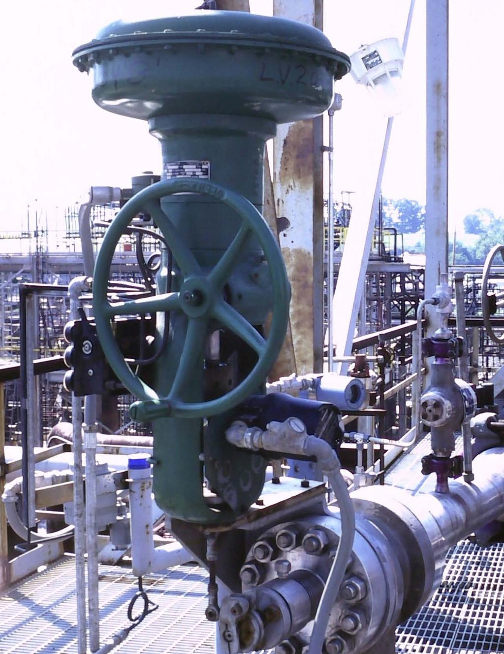
8 Actuation The actuation of MOVs can take many forms, including: Manual bar handles Handwheel gear operator Linear pneumatic actuator Linear hydraulic actuator Electric actuation Stepping actuator Any MOV can be actuated, and field conversion from manual to actuated is possible on most models. Pneumatic actuators Pneumatic actuators are applicable to all of Cameron MOV choke models. They are especially effective for economical, automated control of the M2 and larger choke valves. Accessories such as positioners, limit switches, filter regulators, local pressure controllers, solenoid valves, and more are available with pneumatic actuators. Selecting the most economical size of actuator is determined primarily by the turning torque required to effectively operate the choke. Diaphragm actuators are preferred on many applications as they are more economical than piston types, and they require only 35-psi line pressure to operate. Piston actuators are required if the torque is in excess of, or near, the maximum capabilities of the diaphragm actuators. Pneumatic diaphragm actuated MOV choke. A Cameron representative can assist you in the selection of the proper pneumatic actuator for the specified MOV application. Cameron MOV chokes are easily adapted to pneumatic actuation using ruggedlyconstructed actuator adapters. Electric actuators Electric actuators are most popular for applications on smaller MOV chokes such as the MC10, M1A, and M2. These chokes are designed with actuation in mind and provide for an extremely compact and simple installation. Electrically-actuated MOV chokes are especially applicable to field automated production installations using closed-loop computer control systems. Specific advantages include: Control capability over a wide range of flow rates The capability of electronically controlled positioning Near-linear increasing flow rates with increasing valve opening Dynamic stability at all pressure drop and flow-rate conditions. Availability of valve trim to allow for different ranges of flow rates, while using the same actuator, valve body, and control software system Low energy and torque requirements Selection of electric actuators is primarily determined by the choke turning torque required and the specific control feedback and environmental considerations of the installation. Cameron electrically-actuated MOV choke valves can be provided with adjustable travel stops, a potentiometer for remote valve position readout, electronic speed control, weather-proof and explosion-proof housings, and a manual override. Electrically-actuated inline MOV choke. 6


![The S-15,000 operates at temperatures from 30 to 180 degf [ 34 to 82 degc] in a watertight, marine corrosion-resistant enclosure.](/docs-images/74/70054651/images/9-2.jpg "In subsea applications, the unit has been tested and rated to operate at depths of 4,000 ft.")
9 Stepping actuators The S-15,000 stepping actuator is designed to open and/or close MOV chokes in precise one-degree increments. The capabilities of this heavyduty actuator make it particularly applicable to M3, M3G, M4, and M6 MOVs choke. The S-15,000 draws its name from the amount of torque it delivers, 15,000 in-lb, and is designed to work with either 100 psi pneumatic or 1,000 to 3,000 psi hydraulic fluid supply. The proven design features of the S-15,000 make it one of the top actuators for remote and automated control for locations on land, offshore, or subsea. The S-15,000 operates at temperatures from 30 to 180 degf [ 34 to 82 degc] in a watertight, marine corrosion-resistant enclosure. In subsea applications, the unit has been tested and rated to operate at depths of 4,000 ft. For remote readings of the choke s position, there is a standard 5,000-ohm potentiometer which can be used with a transmitter to provide a feedback signal in milliamps. External position indicators on surface models of the S-15,000 can read percent open, degrees rotated, or bean size for a quick visual reference of MOV position at any given time. The S-15,000 has been tested through 1,000,000 cycles without any malfunction. In the event of a pneumatic or hydraulic supply failure, the actuator will remain locked in its last set position. There is a manual override drive achieved by rotating one of the two hex shafts external to the actuator housing with a wrench. MOV choke with S-15,000 stepping actuator. Because of these features, and the high operational reliability of the S-15,000, it can be specified for any production operation onshore or offshore that requires precise, trouble-free flow control. S-15,000 stepping actuator-cross section view. S-15,000 stepping actuator 7
![MC10 The MC10 choke is a 1-in [25-mm] nominal in-line MOV choke, and is suitable for a wide variety of applications.](/docs-images/74/70054651/images/10-0.jpg "It is commonly used in water and gas injection operations as part of enhanced recovery processes.")
10 MC10 The MC10 choke is a 1-in [25-mm] nominal in-line MOV choke, and is suitable for a wide variety of applications. It is commonly used in water and gas injection operations as part of enhanced recovery processes. The MC10 choke s precise control also has gained acceptance in gas injection and gas lift operations, and production systems. The trim design resists freezing in CO2 service. It also has positive shutoff and adapts easily to field applications utilizing electric, hydraulic, and pneumatic actuators. The standard MC10 choke end connections are 1-in [25-mm] and 2-in [51-mm] female threaded interfaces or 2-in [51-mm] flanges. Other options are available subject to inquiry. Optional Stellite or tungsten carbide outlet wear sleeves are available to protect against cavitation and erosion. A backpressure bean can be added to the choke to provide a second pressure drop to reduce choked flow conditions. MC10 Choke Parts List Key no. Description Qty Standard material 1 Body 1 Ni-Al-Bz or stainless steel 2 O-ring 2 Aflas 3 Backup ring 2 Teflon 4 Dowel pin 4 Stainless steel 5 Capscrew 6 Alloy 6 O-ring 1 Teflon 7 Outlet hub 1 Ni-Al-Bz or stainless steel 8 Back disc 1 Ceramic or tungsten carbide 9 O-ring 1 Teflon 10 Dowel pin 1 Stainless steel 11 Front disc 1 Ceramic or tungsten carbide 12 Calibration band 1 Stainless steel 13 Drive screw 2 Stainless steel 14 Handle 1 Alloy steel 15 Indicator ring 1 Stainless steel 16 Rotator 1 Ni-Al-Bz or stainless steel - Wear sleeve 1 Stellite or tungsten carbide Recommended spare parts for one year of operation. Optional 12, Wear sleeve (optional) A 8
![MC10 Physical Dimensions Inlet and outlet connections A, in [mm] Weight, lb [kg] 1 in [25 mm] Female NPT, Ni-Al-Bz 8.87 [225] 16 [7] 1 in [25 mm] Female NPT, C.S., S.S. 10.](/docs-images/74/70054651/images/11-0.jpg "30 [262] 20 [9] 2 in [51 mm] Female NPT 10.30 [262] 20 [9] 2 in [51 mm] ANSI Class 900 RF 10.30 [262] 64 [29] 2 in [51 mm] ANSI Class 900 RTJ 10.30 [262] 64 [29] 2 in [51 mm] ANSI Class 1500 RF 10.")
![30 [262] 64 [29] 2 in [51 mm] ANSI Class 1500 RTJ 10.30 [262] 64 [29] 21/16 in [52.4 mm] 3000 API 10.](/docs-images/74/70054651/images/11-1.jpg "30 [262] 64 [29] MC10 trim Maximum body pressure rating, psi ANSI Class 1500 Trim size (number of holes) diameter, in (1) 1/8 (2) 1/8 (1) 1/4 (2) 1/4 (1) ½ (2) ½ (2) 5/8 0.33 0.70 1.60 3.33 6.85 14.")

11 MC10 Physical Dimensions Inlet and outlet connections A, in [mm] Weight, lb [kg] 1 in [25 mm] Female NPT, Ni-Al-Bz 8.87 [225] 16 [7] 1 in [25 mm] Female NPT, C.S., S.S [262] 20 [9] 2 in [51 mm] Female NPT [262] 20 [9] 2 in [51 mm] ANSI Class 900 RF [262] 64 [29] 2 in [51 mm] ANSI Class 900 RTJ [262] 64 [29] 2 in [51 mm] ANSI Class 1500 RF [262] 64 [29] 2 in [51 mm] ANSI Class 1500 RTJ [262] 64 [29] 21/16 in [52.4 mm] 3000 API [262] 64 [29] MC10 trim Maximum body pressure rating, psi ANSI Class 1500 Trim size (number of holes) diameter, in (1) 1/8 (2) 1/8 (1) 1/4 (2) 1/4 (1) ½ (2) ½ (2) 5/ Flow coefficient C v (maximum) C v values given in table are subject to variation depending on valve end connections and options such as wear sleeves and backpressure beans. Valve pressure rating for specific configurations can be less depending on end connections, valve style and use of ceramic or tungsten-carbide trim. MC10 flow curves 20 Bean size, 1/64 in equivalent area (2) 5/8 in (pie) (2) 1/2 in 45.3 C v 10 (1) 1/2 in (2) 1/4 in (1) 1/4 in Degree open,
![MC20 The MC20 choke is a 2-in [51-mm] nominal in-line MOV choke, with suitability for multiple applications, particularly water, and gas injection operations to achieve EOR.](/docs-images/74/70054651/images/12-0.jpg "The MC20 choke s precise control also has gained acceptance in gas injection and gas lift operations, and production systems. The trim design resists freezing in CO2 service.")
12 MC20 The MC20 choke is a 2-in [51-mm] nominal in-line MOV choke, with suitability for multiple applications, particularly water, and gas injection operations to achieve EOR. The MC20 choke s precise control also has gained acceptance in gas injection and gas lift operations, and production systems. The trim design resists freezing in CO2 service. It also has positive shutoff and easily adapts to field applications utilizing electric, hydraulic, and pneumatic actuators. The MC20 choke is available with 2-in [51-mm] female threaded interfaces or 2- to 4-in [51- to 102-mm] flanges. Other interface options are available subject to inquiry. Optional Stellite or tungsten-carbide outlet wear sleeves are available to protect against cavitation and erosion. A backpressure bean can be added to the choke to provide a second pressure drop to reduce choked flow conditions. Trim size (number of holes) diameter, in Maximum body pressure rating, psi API Class 5,000 (2) 1/ (1) ½ 6.22 (2) ½ (2) 3/ (2) (2) 11/ Flow coefficient C v (maximum) C v values given in table are subject to variation depending on valve end connections and options such as wear sleeves and backpressure beans. Valve pressure rating for specific configurations can be less depending on end connections, valve style and use of ceramic or tungsten-carbide trim. MC20 Choke Parts List Key no. Description Qty Standard material 1 Outlet hub 1 Ni-Al-Bz or stainless steel 2 Nut 16 Alloy 3 Stud 8 Alloy 4 Dowel pin 5 Stainless steel 5 O-ring 3 Teflon 6 Front disc 1 Ceramic or tungsten carbide 7 Belleville washer 1 Inconel Backup ring 1 Teflon 9 Rotor 1 Alloy steel or stainless steel 10 Body 1 Alloy steel or stainless steel 11 O-ring 1 Teflon 12 Screw 1 Stainless steel 13 Nameplate 2 Stainless steel 14 Handle 1 Alloy steel 15 Calibration band 1 Stainless steel 16 Indicator ring 1 Stainless steel 17 Back disc 1 Ceramic or tungsten carbide 18 O-ring 2 Buna-N 19 Drive screw 4 Stainless steel - Wear sleeve 1 Stellite or tungsten carbide Recommended spare parts for one year of operation. Optional , , Wear sleeve (optional) A
![MC20 Physical Dimensions Inlet and outlet connections A Weight in mm lb kg 2 in [51 mm] Female NPT 10.39 264 64 29 2 in [51 mm] ANSI Class 600 RF 16.59 421 84 38 2 in [51 mm] ANSI Class 600 RTJ 16.](/docs-images/74/70054651/images/13-0.jpg "71 424 84 38 2 in [51 mm] ANSI Class 900 RF 18.81 478 112 51 2 in [51 mm] ANSI Class 900 RTJ 18.93 481 112 51 2 in [51 mm] ANSI Class 1,500 RF 18.81 478 112 51 2 in [51 mm] ANSI Class 1,500 RTJ 18.")
![93 481 112 51 3 in [76 mm] ANSI Class 600 RF 17.31 440 100 46 3 in [76 mm] ANSI Class 600 RTJ 17.43 443 100 46 3 in [76 mm] ANSI Class 900 RF 18.81 478 122 56 3 in [76 mm] ANSI Class 900 RTJ 18.](/docs-images/74/70054651/images/13-1.jpg "93 481 122 56 3 in [76 mm] ANSI Class 1,500 RF 20.00 483 160 73 3 in [76 mm] ANSI Class 1,500 RTJ 20.12 486 160 73 4 in [102 mm] ANSI Class 600 RF 18.81 478 138 63 4 in [102 mm] ANSI Class 600 RTJ 18.")
13 MC20 Physical Dimensions Inlet and outlet connections A Weight in mm lb kg 2 in [51 mm] Female NPT in [51 mm] ANSI Class 600 RF in [51 mm] ANSI Class 600 RTJ in [51 mm] ANSI Class 900 RF in [51 mm] ANSI Class 900 RTJ in [51 mm] ANSI Class 1,500 RF in [51 mm] ANSI Class 1,500 RTJ in [76 mm] ANSI Class 600 RF in [76 mm] ANSI Class 600 RTJ in [76 mm] ANSI Class 900 RF in [76 mm] ANSI Class 900 RTJ in [76 mm] ANSI Class 1,500 RF in [76 mm] ANSI Class 1,500 RTJ in [102 mm] ANSI Class 600 RF in [102 mm] ANSI Class 600 RTJ in [102 mm] ANSI Class 900 RF in [102 mm] ANSI Class 900 RTJ in [102 mm] ANSI Class 1,500 RF in [102 mm] ANSI Class 1,500 RTJ /16 in [52.4 mm] API 3, /16 in [52.4 mm] API 5, /16 in [65.09 mm] API 3, /16 in [65.09 mm] API 5, /8 in [79.4 mm] API 3, /8 in [79.4 mm] API 5, /16 in [103.2 mm] API 3, /16 in [103.2 mm] API 5, MC20 flow curves 50 Bean size, 1/64 in equivalent area (2) 1 in (pie) C v 30 (2) 3/4 in (2) 1/2 in Degree open, (1) 1/2 in (2) 1/4 in
14 M1A Like the MC10 choke, the M1A has the same economical, easy to replace trim. The M1A choke is available with 1-in [25-mm] and 2-in [51-mm] male threaded, 2-in [51-mm] male threaded, 2-in [51-mm] flanged or butt-weld configurations. Other end connections are available as required. Optional tungsten-carbide or Stellite outlet wear sleeves are available on the M1A choke for erosive or cavitation conditions. The M1A choke is designed for easy automation. You can change from manual to actuated right in the field. No additional brackets or adjustments are required for most models. M1A trim Trim size (number of holes) diameter, in (1) 1/8 (2) 1/8 (1) ¼ (2) ¼ (1) ½ (2) ½ (2) 5/8 Maximum body pressure rating, psi API Class 5, Flow coefficient C v (maximum) C v values given in table are subject to variation depending on valve end connections and options such as wear sleeves and backpressure beans. Valve pressure rating for specific configurations can be less depending on end connections, valve style and use of ceramic or tungsten-carbide trim. M1A Choke Parts List Key no. Description Qty Standard material 1 Outlet hub 1 Ni-Al-Bz, alloy steel, or stainless steel 2 Capscrew 8 Alloy 3 O-ring 2 Buna-N, Viton or aflas 4 Carrier 1 Ni-Al-Bz, alloy steel, or stainless steel 5 Body 1 Ni-Al-Bz, alloy steel, or stainless steel 6 O-ring 1 Buna-N, viton, or aflas 7 Front disc 1 Ceramic or tungsten carbide 8 Thrust bearing 1 Delrin 9 O-ring 2 Buna-N, Viton, or aflas 10 Backup ring 1 Teflon 11 Turning fork 1 Ni-Al-Bz or stainless steel 12 Indicator plate 1 Stainless steel 13 Bar handle 1 Ni-Al-Bz 14 Plate screw 2 Stainless steel 15 Stem screw 1 Stainless steel 16 Back disc 1 Ceramic or tungsten carbide 17 O-ring 1 Buna-N, viton, or aflas 18 Backup ring 1 Teflon 19 Inlet hub 1 Ni-Al-Bz, alloy steel, or stainless steel 20 Thumbscrew 1 Alloy steel Wear sleeve (optional) 1 Tungsten carbide or stellite Recommended spare parts for one year of operation ,
![M1A Physical Dimensions Inlet and outlet connections A B Weight in mm in mm lb kg 1 in [25 mm] Female NPT 8.11 206 6.00 152 28 13 2 in [51 mm] Female NPT 9.06 230 6.](/docs-images/74/70054651/images/15-0.jpg "95 177 29 13 2 in [51 mm] Male NPT 8.11 206 6.00 152 28 13 2 in [51 mm] Butt Weld 8.00 203 5.89 150 28 13 2 in [51 mm] ANSI Class 600 RF 9.88 251 7.77 197 48 22 2 in [51 mm] ANSI Class 600 RTJ 9.")
![94 252 7.83 199 48 22 2 in [51 mm] ANSI Class 900 RF 9.88 251 7.77 197 76 35 2 in [51 mm] ANSI Class 900 RTJ 9.94 252 7.83 199 76 35 2 in [51 mm] ANSI Class 1,500 RF 9.88 251 7.77 197 76 35 2 in [51 mm] ANSI Class 1,500 RTJ 9.](/docs-images/74/70054651/images/15-1.jpg "94 252 7.83 199 76 35 21/16 in [52.4 mm] 2,000 API 9.94 252 7.83 199 48 22 21/16 in [52.4 mm] 3,000 API 9.94 252 7.83 199 76 35 21/16 in [52.4 mm] 5,000 API 9.94 252 7.83 199 76 35 M1A dimensions B A 4.")
15 M1A Physical Dimensions Inlet and outlet connections A B Weight in mm in mm lb kg 1 in [25 mm] Female NPT in [51 mm] Female NPT in [51 mm] Male NPT in [51 mm] Butt Weld in [51 mm] ANSI Class 600 RF in [51 mm] ANSI Class 600 RTJ in [51 mm] ANSI Class 900 RF in [51 mm] ANSI Class 900 RTJ in [51 mm] ANSI Class 1,500 RF in [51 mm] ANSI Class 1,500 RTJ /16 in [52.4 mm] 2,000 API /16 in [52.4 mm] 3,000 API /16 in [52.4 mm] 5,000 API M1A dimensions B A 4.88 M1A flow curves 15 Bean size, 1/64 in equivalent area 56.4 (2) 5/8 in (pie) (2) 1/2 in C v 5 (1) 1/2 in 32.0 (2) 1/4 in Degree open 13
![M2 The M2 choke is a compact, 2-in [51-mm] nominal MOV choke used widely throughout the world primarily for wellhead and production applications.](/docs-images/74/70054651/images/16-0.jpg "This closed die-forged body valve has a threaded bonnet for easy maintenance and is available in several versions. The standard M2 choke is bar-handle operated.")
16 M2 The M2 choke is a compact, 2-in [51-mm] nominal MOV choke used widely throughout the world primarily for wellhead and production applications. This closed die-forged body valve has a threaded bonnet for easy maintenance and is available in several versions. The standard M2 choke is bar-handle operated. Handwheel operators, electric, and pneumatic actuators also are available M2 Choke Parts List Key no. Description Qty Standard material 1 Body 1 Alloy steel 2 Disc assembly, back 1 Ceramic/SS or tungsten carbide/ss 3 O-ring, bonnet 1 Viton 4 Disc assembly, front 1 Ceramic/SS or tungsten carbide/ss 5 Thrust bearing 1 Delrin 6 O-ring, turning fork 1 Viton 7 Backup ring 3 Teflon 8 Bonnet 1 Alloy steel 9 Dowel pin 4 High-strength alloy 10 Turning fork 1 Alloy steel 11 Mounting flange 1 Alloy steel 12 Calibration band 1 Stainless steel 13 Sheet metal screw 4 Alloy steel 14 Capscrew 1 Stainless steel 15 Stud 8 High-strength alloy 16 Nut 8 High-strength alloy 17 Pointer 1 Stainless steel 18 Shaft bushing 1 Turcite-A 19 O-ring, turning fork 2 Viton 20 O-ring, bonnet 1 Buna-N 21 O-ring, back disc assembly 1 Viton 22 Indicat or head 1 Alloy steel 23 Gear operator, handwheel 1 Alloy steel 24 Key 1 High-strength alloy 25 Drive shaft assembly 1 Alloy steel 26 Capscrew 4 High-strength alloy 27 Mounting plate 1 Alloy steel 28 Drive screw 4 Stainless steel 29 Valve ID tag 1 Stainless steel Recommended spare parts for one year of operation , M2 chokes, manually operated. 14
17 M2 Choke Physical Dimensions Inlet and outlet connections A B Weight in mm in mm lb kg 2 in [51 mm] ANSI Class 600 RF in [51 mm] ANSI Class 600 RTJ in [51 mm] ANSI Class 900 RF in [51 mm] ANSI Class 900 RTJ in [51 mm] ANSI Class 1500 RF in [51 mm] ANSI Class 1500 RTJ in [51 mm] ANSI Class 2500 RF in [51 mm] ANSI Class 2500 RTJ /16 in [52.4 mm] 2,000 API /16 in [52.4 mm] 3,000 API /16 in [52.4 mm] 5,000 API /16 in [65.09 mm] 2,000 API /16 in [65.09 mm] 3,000 API /16 in [65.09 mm] 5,000 API in [76 mm] ANSI Class 600 RF in [76 mm] ANSI Class 600 RTJ in [76 mm] ANSI Class 900 RF in [76 mm] ANSI Class 900 RTJ in [76 mm] ANSI Class 1500 RF in [76 mm] ANSI Class 1500 RTJ in [76 mm] ANSI Class 2500 RF in [76 mm] ANSI Class 2500 RTJ /8 in [79.4 mm] 2,000 API /8 in [79.4 mm] 3,000 API /8 in [79.4 mm] 5,000 API /16 in [42.9 mm] BX-150, 10, /16 in [46 mm] BX-151, 10, /16 in [52.4 mm] BX-152, 10, /16 in [65.09 mm] BX-153, 10, M2 dimensions B A B M2 flow curves 40 A 7.25 C C 12 Dimensions C Adj: HW Gear = in C Adj: Bar Handle = 7.48 in C Positive = 5.00 in Bean size, 1/64 in equivalent area (2) 1 in (pie) 90.0 M2 trim Trim size (number of holes) diameter, in (1) 1/8 (2) 1/8 (1) ¼ (2) ¼ (1) ½ (2) ½ (2) 5/8 (2) 3/4 (2) 7/8 (2) 1 Body maximum pressure rating API 10, (special) (special) Flow coefficient C v (maximum) C v values given in table are subject to variation depending on valve end connections and options such as wear sleeves and backpressure beans. Valve pressure rating for specific configurations can be less depending on end connections, valve style and use of ceramic or tungsten-carbide trim. C v (2) 7/8 in (2) 3/4 in (2) 1/2 in (1) 1/2 in 23.0 (2) 1/4 in (1) 1/4 in 0 (2) 1/8 in Degree open, 15
18 M3 The M3 choke is a 3-in [76-mm] nominal MOV that is used worldwide in applications where high flow capacity is required. It is primarily used in surface wellhead and production applications. As with all MOV models, the M3 choke is available with multiple actuation options, including the S-15,000 stepping actuator. It also is available with various end connection options to suit specific requirements. M3 Choke Parts List Key no. Description Qty Standard material 1 Body 1 Alloy steel 2 Outlet flange assembly 1 Alloy steel 3 Front disc assembly 1 Ceramic/SS or tungsten carbide/ss 4 Back disc assembly 1 Ceramic/SS or tungsten carbide/ss 5 Calibration band 1 Stainless steel 6 Turning fork 1 Alloy steel 7 Bonnet 1 Alloy steel 8 Capscrew 8 Alloy 9 Capscrew 8 Alloy 10 Dowel pin 7 Stainless steel 11 Gear operator, handwheel 1 Alloy steel 12 Thrust bearing 1 Delrin 13 Spacer ring 1 Alloy steel 14 Gear operator adapter 1 Alloy steel 15 Drive shaft assembly 1 Alloy steel 16 Indicator head 1 Alloy steel 17 Sheet metal screw 2 Alloy steel 18 Capscrew 2 High-strength alloy 19 Capscrew 8 High-strength alloy 21 Shaft bushing 1 Turcite-a 22 Key 1 High strength alloy 24 O-ring, turning fork 1 Viton 25 O-ring, turning fork 2 Viton 26 O-ring, outlet spool 1 Viton 27 O-ring, outlet spool 2 Viton 28 O-ring, bonnet 1 Viton 29 O-ring, bonnet 1 Viton 30 O-ring, bonnet 1 Buna-N 31 O-ring, back disc assembly 1 Viton 32 Backup ring 3 Teflon 33 Flat washer 2 Alloy steel 34 Drive screw 4 Stainless steel 35 Valve ID tag 1 Stainless steel Recommended spare parts for one year of operation. 33, , , ,
19 M3 Choke Physical Dimensions Inlet and outlet connections A B Weight in mm in mm lb kg 31/8 in [79.4 mm] 2,000 API /8 in [79.4 mm] 3,000 API /8 in [79.4 mm] 5,000 API in [76 mm] ANSI Class 600 RF in [76 mm] ANSI Class 600 RTJ in [76 mm] ANSI Class 900 RF in [76 mm] ANSI Class 900 RTJ in [76 mm] ANSI Class 1500 RF in [76 mm] ANSI Class 1500 RTJ in [76 mm] ANSI Class 2500 RF in [76 mm] ANSI Class 2500 RTJ /16 in [103 mm] 2,000 API /16 in [103 mm] 3,000 API /16 in [103 mm] 5,000 API in [102 mm] ANSI Class 600 RF in [102 mm] ANSI Class 600 RTJ in [102 mm] ANSI Class 900 RF in [102 mm] ANSI Class 900 RTJ in [102 mm] ANSI Class 1500 RF in [102 mm] ANSI Class 1500 RTJ in [102 mm] ANSI Class 2500 RF in [102 mm] ANSI Class 2500 RTJ M3 dimensions 9 B A 8 12 C Dimensions C Adj: HW Gear = in C Positive = 6.12 in M3 trim Trim size (number of holes) diameter, in (1) ¼ (2) ¼ (1) ½ (2) ½ (2) 3/4 (2) 1 (2) 13/16 (2) 11/4 (2) 1.41 Body maximum pressure rating ANSI class Flow coefficient C v (maximum) C v values given in table are subject to variation depending on valve end connections and options such as wear sleeves and backpressure beans. Valve pressure rating for specific configurations can be less depending on end connections, valve style and use of ceramic or tungsten-carbide trim. M3 flow curves C v (2) 1.41 in (pie) Bean size, 1/64 in equivalent area (2) 11/4 in (pie) (2) 13/16 in (2) 1 in (2) 3/4 in Bean size, 1/64 in Degree open, 17
20 M3G The M3G choke is a specially designed 3-in [76-mm] nominal MOV that has been used in drilling choke applications for more than 15 years. Built for severe abrasive service, it has a working pressure up to 10,000 psi and is capable of taking a full 10,000-psi pressure drop with tungsten-carbide discs. The M3G choke is well suited to high-pressure gas letdown applications thanks to its enlarged outlet design which permits 4- to 6-in [102-to 152-mm] flanges to be attached directly to the body for gas expansion. The discs are located near the enlarged outlet, allowing high velocity fluids and particles to pass through into the expanded cavity. The resulting deceleration reduces wear on the choke outlet. M3G trim Trim size (number of holes) diameter, in (1) ¼ (2) ¼ (1) ½ (2) ½ (2) 3/4 (2) 1 (2) 13/16 (2) 11/4 (2) 1.41 Body maximum pressure rating psi API 10, Flow coefficient C v (maximum) C v values given in table are subject to variation depending on valve end connections and options such as wear sleeves and backpressure beans. Valve pressure rating for specific configurations can be less depending on end connections, valve style and use of ceramic or tungsten-carbide trim , , , 21 15, M3G Choke Parts List Key Description Qty Standard material no. Key no. Description Qty Standard material 1 Body 1 Alloy steel 19 O-ring, outlet spool 1 Viton 2 Outlet flange assembly 1 Alloy steel 20 O-ring, bonnet 1 Buna-N 3 Back disc assembly 1 Ceramic/SS or tungsten carbide/ss 21 Backup ring 3 Teflon 4 Front disc assembly 1 Ceramic/SS or tungsten carbide/ss 27 Gear operator, handwheel 1 Alloy steel 5 Calibration band 1 Stainless steel 28 Adapter for gear assembly 1 Alloy steel 6 Turning fork 1 Alloy steel 29 Drive shaft assembly 1 Alloy steel 7 Bonnet 1 Alloy steel 30 Capscrew 2 High-strength alloy 8 Capscrew 12 Alloy 31 Capscrew 4 High-strength alloy 9 Capscrew 16 Alloy 32 Capscrew 6 High-strength alloy 11 Sheet metal screw 2 Stainless steel 33 Key 1 High-strength alloy 12 Thrust bearing 1 Delrin 36 Indicator head 1 Alloy steel 13 Shaft bushing 1 Turcite-a 37 Spacer ring 1 Alloy steel 14 O-ring, turning fork 2 Viton 38 Dowel pin 7 Stainless steel 15 O-ring, turning fork 1 Viton 39 Flat washer 2 Alloy steel 16 O-ring, bonnet 1 Viton 40 Drive screw 4 Stainless steel 17 O-ring, bonnet 1 Viton 41 Valve ID tag 1 Stainless steel 18 O-ring, back disc assembly 1 Viton Recommended spare parts for one year of operation. 18
21 M3G Choke Physical Dimensions Inlet connections Outlet connections A B Weight in mm in mm lb kg 3 in [76 mm] ANSI 600 RF 4 in [102 mm] ANSI 600 RF in [76 mm] ANSI 600 RTJ 4 in [102 mm] ANSI 600 RTJ in [76 mm] ANSI 900 RF 4 in [102 mm] ANSI 900 RF in [76 mm] ANSI 900 RTJ 4 in [102 mm] ANSI 900 RTJ in [76 mm] ANSI 1500 RF 4 in [102 mm] ANSI 1500 RF in [76 mm] ANSI 1500 RTJ 4 in [102 mm] ANSI 1500 RTJ in [76 mm] ANSI 2500 RF 4 in [102 mm] ANSI 2500 RF in [76 mm] ANSI 2500 RTJ 4 in [102 mm] ANSI 2500 RTJ /8 in [79.4 mm] API 2,000 41/16 in [103 mm] API 2, /8 in [79.4 mm] API 3,000 41/16 in [103 mm] API 3, /8 in [79.4 mm] API 5,000 41/16 in [103 mm] API 5, in [102 mm] ANSI 600 RF 6 in [152 mm] ANSI 600 RF in [102 mm] ANSI 600 RTJ 6 in [152 mm] ANSI 600 RTJ in [102 mm] ANSI 900 RF 6 in [152 mm] ANSI 900 RF in [102 mm] ANSI 900 RTJ 6 in [152 mm] ANSI 900 RTJ in [102 mm] ANSI 1,500 RF 6 in [152 mm] ANSI 1,500 RF in [102 mm] ANSI 1500 RTJ 6 in [152 mm] ANSI 1500 RTJ in [102 mm] ANSI 2500 RF 6 in [152 mm] ANSI 2500 RF in [102 mm] ANSI 2500 RTJ 6 in [152 mm] ANSI 2500 RTJ /16 in [103 mm] API 2,000 71/16 in [179 mm] API 2, /16 in [103 mm] API 3,000 71/16 in [179 mm] API 3, /16 in [103 mm] API 5,000 71/16 in [179 mm] API 5, /16 in [65 mm] BX K 31/16 in [78 mm] BX K /16 in [78 mm] BX K 31/16 in [78 mm] BX K /16 in [103 mm] BX K 41/16 in [103 mm] BX K M3G dimensions 9 M3G flow curves (2) 1.41 in (pie) Bean size, 1/64 in equivalent area (2) 11/4 in (pie) (2) 13/16 in B A C C v 40 (2) 1 in (2) 3/4 in Bean size, 1/64 in Dimensions C Adj: HW Gear = in C Positive = 6.12 in Degree open, 19
22 M4 20 The M4 choke is a 4-in [102-mm] nominal MOV that has found a great deal of acceptance worldwide, particularly in large volume production and in water-injection applications in the North Sea, Middle East, and Alaskan North Slope. This choke is extensively used in surface wellhead and production applications and has gained wide acceptance as a high-quality subsea choke. The M4 choke affords easy actuation from a variety of pneumatic diaphragm actuators to the Cameron S-15,000 stepping actuator. M3 Choke Parts List Key no. Description Qty Standard material 1 Body 1 Alloy steel 2 Outlet flange assembly 1 Alloy steel 3 Front disc assembly 1 Ceramic/SS or tungsten carbide/ss 4 Back disc assembly 1 Ceramic/SS or tungsten carbide/ss 5 Calibration band 1 Stainless steel 6 Turning fork 1 Alloy steel 7 Bonnet 1 Alloy steel 8 Capscrew 12 Alloy 9 Capscrew 12 Alloy 10 Dowel pin 6 Stainless steel 11 Bearing race 1 Alloy steel 12 Thrust needle bearing 1 Alloy steel 13 Thrust bearing race 1 Alloy steel 14 O-ring, outlet spool 1 Viton 15 Backup ring, outlet spool 1 Teflon 16 O-ring, outlet spool 1 Viton 17 O-ring, back disc assembly 1 Viton 18 O-ring, bonnet 1 Viton 19 Backup ring 2 Teflon 20 O-ring, bonnet 1 Viton 21 O-ring, turning fork 1 Viton 22 Backup ring 3 Teflon 23 O-ring, turning fork 2 Viton 24 Key 1 High-strength alloy 25 Sheet metal screw 2 Stainless steel 26 Gear operator, handwheel 1 Alloy steel 27 Adapter for gear assembly 1 Alloy steel 28 Spacer ring 1 Alloy steel 29 Drive bushing 1 Alloy steel 30 Indicator head 1 Stainless steel 31 Capscrew 2 High-strength alloy 32 Nut 4 High-strength alloy 33 Stud 4 High-strength alloy 34 Key 1 High-strength alloy 35 Key retainer plug 1 Alloy steel 36 Capscrew 4 High-strength alloy 37 Drive screw 4 Stainless steel 38 Valve ID tag 1 Stainless steel Recommended spare parts for one year of operation , , 20 18,19 22, 23 21, 22 37, , , 16 14
23 M4 Physical Dimensions Inlet and outlet connections A ±.12 in B ±.12 in Weight in mm in mm lb kg 4 in [102 mm] ANSI Class 600 RF in [102 mm] ANSI Class 600 RTJ in [102 mm] ANSI Class 900 RF in [102 mm] ANSI Class 900 RTJ in [102 mm] ANSI Class 1500 RF in [102 mm] ANSI Class 1500 RTJ in [102 mm] ANSI Class 2500 RF in [102 mm] ANSI Class 2500 RTJ /16 in [103 mm] API 2, /16 in [103 mm] API 3, /16 in [103 mm] API 5, in [152 mm] ANSI Class 600 RF in [152 mm] ANSI Class 600 RTJ in [152 mm] ANSI Class 900 RF in [152 mm] ANSI Class 900 RTJ in [152 mm] ANSI Class 1500 RF in [152 mm] ANSI Class 1500 RTJ in [152 mm] ANSI Class 2500 RF in [152 mm] ANSI Class 2500 RTJ /16 in [179 mm] API 2, /16 in [179 mm] API 3, M4 dimensions B A Dimensions C Adj: HW Gear = in C Positive = 6.25 in M4 trim Trim size (number of holes) diameter, in (1) ½ (2) ½ (2) 3/4 (2) 1 (2) 13/16 (2) 11/2 (2) 2 (2) 25/16 Body maximum pressure rating ANSI class Flow coefficient C v (maximum) C v values given in table are subject to variation depending on valve end connections and options such as wear sleeves and backpressure beans. Valve pressure rating for specific configurations can be less depending on end connections, valve style and use of ceramic or tungsten-carbide trim. M4 flow curves C v (2) 25/16 in (pie) Bean size, 1/64 in equivalent area (2) 2.00 in (2) 1.50 in (2) 13/16 in (2) 1.00 in (2) 3/4 in Degree open, 21
![M6 The M6 choke is a 6-in [152-mm] nominal MOV choke, and is the largest MOV-style choke provided by Cameron.](/docs-images/74/70054651/images/24-0.jpg "It has all the features and benefits of the smaller MOVs but at a greatly increased working capacity.")

24 M6 The M6 choke is a 6-in [152-mm] nominal MOV choke, and is the largest MOV-style choke provided by Cameron. It has all the features and benefits of the smaller MOVs but at a greatly increased working capacity. As with all MOV models, the M6 choke is available with multiple actuation options including the S-15,000 stepping actuator. It also is available with various end connection options to suit specific requirements. M6 Choke Parts List Key no. Description Qty Standard material 1 Body 1 Alloy steel 2 Outlet flange assembly 1 Alloy steel 3 Front disc assembly 1 Ceramic/SS or tungsten carbide/ss 4 Back disc assembly 1 Ceramic/SS or tungsten carbide/ss 5 Calibration band 1 Stainless steel 6 Turning fork 1 Alloy steel 7 Bonnet 1 Alloy steel 8 Capscrew 16 Alloy 9 Capscrew 16 Alloy 10 Dowel pin 6 Stainless steel 11 Sheet metal screw 2 Stainless steel 12 Thrust needle bearing 1 Alloy steel 13 Thrust bearing race 2 Alloy steel 14 O-ring, outlet spool 1 Viton 15 O-ring, outlet spool 1 Viton 17 O-ring, back disc assembly 1 Viton 18 O-ring, bonnet 1 Viton 20 O-ring, bonnet 1 Viton 21 O-ring, turning fork 1 Viton 22 Backup ring 3 Teflon 23 O-ring, turning fork 2 Viton 24 Key 1 High-strength alloy 27 Gear operator, handwheel 1 Alloy steel 28 Indicator head 1 Alloy steel 29 Capscrew 2 Stainless steel 30 Spacer ring 1 Alloy steel 31 Gear operator adapter 1 Alloy steel 32 Drive bushing 1 Alloy steel 33 Key 1 High-strength alloy 34 Pointer 1 Stainless steel 35 Pointer riser 1 Alloy steel 36 Capscrew 4 High-strength alloy 37 Stud 8 High-strength alloy 38 Nut 8 High-strength alloy 39 Set screw 1 High-strength alloy 40 Capscrew 4 High-strength alloy 41 Key retainer plug 1 Alloy steel 42 Flow direction label 1 Stainless steel 43 Drive screw 6 Stainless steel 44 Valve ID Tag 1 Stainless Steel Recommended spare parts for one year of operation , , , , , ,
25 M6 Choke Physical Dimensions Inlet and outlet connections A ±.12 in B ±.12 in Weight in mm in mm lb kg 6 in [152 mm] ANSI Class 600 RF in [152 mm] ANSI Class 600 RTJ in [152 mm] ANSI Class 900 RF in [152 mm] ANSI Class 900 RTJ in [152 mm] ANSI Class 1500 RF in [152 mm] ANSI Class 1500 RTJ /16 in [179 mm] API 3, in [203 mm ] ANSI Class 600 RF in [203 mm ] ANSI Class 600 RTJ in [203 mm ] ANSI Class 900 RF in [203 mm ] ANSI Class 900 RTJ in [203 mm ] ANSI Class 1500 RF in [203 mm ] ANSI Class 1500 RTJ M6 dimensions B A 18 C M6 trim Trim size (number of holes) diameter, in (2) 3/4 (2) 1 (2) 13/16 (2) 11/2 (2) 2 (2) 25/16 (2) 31/8 Body maximum pressure rating ANSI class Flow coefficient C v (maximum) C v values given in table are subject to variation depending on valve end connections and options such as wear sleeves and backpressure beans. Valve pressure rating for specific configurations can be less depending on end connections, valve style and use of ceramic or tungsten-carbide trim. M6 flow curves (2) 31/8 in (pie) Dimension C Adj: HW Gear = in Bean size, 1/64 in equivalent area (2) 25/16 in (pie) C v 200 (2) 2.00 in (2) 1.5 in Degree open, 23

26 MOV Positive Chokes Most of our MOV chokes have the capability of being field converted from the standard rotating disc design to a positive configuration. Conversely, positive chokes can be field converted to adjustable rotating discs when desired. Removal of beans requires no special tools and each bean is marked in 64th of an inch for easy identification. In-line Positive Choke Size Standard connections Max. CWP Max. bean Bean material 2 in [51 mm] 1 in [25 mm] or 2 in [51 mm] 1-in female threaded 2-in male threaded buttweld 3 in [76 mm] 3-in buttweld 6,000 psi 128 /64s 4 in [102 mm] 4-in buttweld 5,000 psi 176 /64s 5,000 psi 74 /64s Either stainless steel or tungsten carbide come in sizes up to 66/ 64s. All larger orifice sizes come in stainless steel. In-line positive chokes In-line positive chokes are available for either standard service or high-temperature applications. Standard chokes are constructed with O-ring seals and are recommended for temperatures less than 225 degf [107 degc]. High-temperature positive chokes are furnished with spiral-wound flexitallic gaskets and are designed for temperatures up to 750 degf [399 degc]. Servicing is a simple matter of loosening the hub flange bolts and partially disassembling the connection to allow the bean to be removed or replaced as required. M2 Positive Choke Parts List Key no. Description Quantity 1 Body 1 2 Bonnet 1 3 Seat 1 4 Bean insert 1 5 O-ring, seat 1 6 O-ring, bean 1 7 O-ring, bonnet 1 8 O-ring, bonnet 1 9 O-ring, bonnet 1 Recommended spare parts for one year of operation
27 M3 Positive Choke Parts List Key no. Description Quantity 1 Capscrew 16 2 Outlet flange assembly 1 3 Dowel pins 3 4 O-ring, outlet spool and bonnet 4 5 O-ring, bean carrier 1 6 Bean carrier 1 7 Bean insert 1 8 O-ring, bean 1 9 Retainer plate 1 10 Retainer post 2 12 Body 1 13 Bonnet 1 Recommended spare parts for one year of operation M4 Positive Choke Parts List Key no. Description Quantity Capscrew 24 2 Outlet flange assembly 1 3 Dowel pins 3 4 O-ring, outlet spool 1 5 O-ring, bean carrier 1 6 Bean carrier 1 7 Bean assembly 1 8 O-ring, bean 1 9 Retainer plate 1 10 Retainer post 2 11 O-ring, outlet spool 1 12 Body 1 13 Bonnet 1 14 O-ring, bonnet 1 15 O-ring, bonnet 1 13 Recommended spare parts for one year of operation MOV Positive Bean Valve type Available positive bean sizes, in M2 2/64 to 74/64 M3 2/64 to 96/64 M3G 2/64 to 96/64 M4 2/64 to 176/64 M6 176/64 to 304/64 Bean material Either stainless steel or tungsten carbide come in sizes up to 66/64s. All larger orifice sizes come in stainless steel. 25
28 Technical reference 8620 Cameron Body Material Chart (Subject to change per Q.A./Engineering Evaluation) Style 0 Style 8 Style 4 Service CO2 with or without H2S Standard service H2S temperature range, Partial pressure, psi degf [degc] ASTM API Type: 1,2,3 NACE MR (3 30) to 230 degf A350 LF A352LCB/LCC 8620 A182 F6NM Inconel 625 [ 46 to 110 degc] Inconel 600 Style C 4130 A350 LF A487 CA6NM Incoloy Alloy 20 Duplex A350 LF2 A351 CF8M 316 SS 8351 CF3 A487 CA6NM A182 F6NM 20 to 230 degf A 487 4N 8620 A 487 4N SS Inconel 625 [ 29 to 110 degc] 8720 A Inconel 600 A AA352LCC A182 F6a Incoloy 825 A352LCB A105 A217 CA15 Alloy 20 A216 WCB Duplex 316* 410 SS 20 to 350 degf [ 29 to 110 degc] A105 A216 WCB A Additional requirement: Hardness HRC22 max. as heat-treated seawater without H2S. 316 SS for high CO2 plus chloride. Ferralium 255 or Sandvik Includes Charpy impact testing for Style C. Equivalent regarding corrosive resistance A SS A182 F6a A217 CA15 Inconel 625 Inconel 600 Incoloy 825 Alloy 20 Duplex SS Sea water Inconel 625 Inconel 600 Incoloy 825 Alloy 20 Duplex Inconel 625 Inconel 600 Incoloy 825 Alloy 20 Duplex NAIA Bronze Inconel 625 Inconel 600 Incoloy 825 Alloy 20 Duplex NAIA Bronze HCI environment Hastelloy C276 Inconel 625 Alloy 20 Duplex Hastelloy C276 Inconel 625 Alloy 20 Duplex Hastelloy C276 Inconel 625 Alloy 20 Duplex 26 MOV Trim Selection, Flow Coefficient C v (Maximum) Valve type Body maximum pressure rating, psi Trim size (number of holes, diameter) 1, 1/8 2, 1/8 1, 1/4 2, 1/4 1, 1/2 2, 1/2 2, 5/8 2, 3/4 2, 7/8 2, 1 2, 13/16 2, 11/4 2, , 11/2 2, 2 2, 25/16 2, 31/8 MC20 API 5, MIA API 5, MC10 ANSI Class M2 API 10, M3 API 6, M3G API 10, M4 API 6, M6 API 3, Valve pressure rating for specific configurations can be less depending on end connections, valve style and use of ceramic- or tungsten-carbide trim. C v values given in table are subject to variation depending on valve end connections and options such as wear sleeves and backpressure beans. Pie-shaped holes. Because of continued research, testing and product improvement programs and flow coefficient, C V values are subject to change.

29 M2 choke with pneumatic actuator.
Multiple Orifice Valve Chokes Precision flow control in a range of applications around the world
 Multiple Orifice Valve Chokes Precision flow control in a range of applications around the world Contents MOV chokes................................................................................2 Multiple
Choke Valves SINCE1958. Unique. Precise. Quality. Reliable.
 SINCE1958 MCX SERIES Choke Valves Unique. Precise. Quality. Reliable. MOV Valve Principle of Operation Taylor Valve Technology Multi Orifice Valve Design Principle Provides Precision Control. The two adjacent
Wellhead Valves. DHV Industries,Inc. DHV Valve Company Inc.
 DHV Industries,Inc. 3451 Pegasus Drive, Bakersfield. CA 93308 U.S.A. Call TollFree: (887) DHV-USA1 Phone: (661) 392-8948 Fax: (661) 392-8947 E-mail: sales@dhvindustries.com Website: www.dhvindustries.com
Multi Orifice Nozzle. Valve (MON) R Series Control Valves R2 R3 R4 R6 R8
 R Series Control Valves R2 R3 R4 R6 R8") Multi Orifice Nozzle (MON) Valve R Series Control Valves R2 R3 R4 R6 R8 R Series Control Valves www.taylorvalve.com The applied principle of Hydrodynamic Energy Conversion Protective Cage and Seat Assembly
Multi Orifice Nozzle (MON) Valve R Series Control Valves R2 R3 R4 R6 R8 R Series Control Valves www.taylorvalve.com The applied principle of Hydrodynamic Energy Conversion Protective Cage and Seat Assembly
N-Line Valves. Severe Service Control Chokes
 Severe Service Control Chokes Introduction continues to provide the highest levels of quality and value to oil and gas producers throughout the world. We manufacture severe service control chokes, engineered
CONTROL CHOKE SINCE1958. Unique. Precise. Quality. Reliable.
 SINCE95 RB SERIES CONTROL CHOKE Unique. Precise. Quality. Reliable. RB SERIES CONTROL VALVES FEATURES Benefits The RB Series Control Valve features several unique design characteristics that minimize wear
Hydra Series Choke Valve **Patent Pending
 Hydra Series Choke Valve product of GI Industries Hydroplex Choke Valve Hydroplex chokes are Multiple Orifice Valves (MOV) specifically designed to control high pressure liquids and gases while providing
Model 5400 / 5450 Control Valve
 Model 5400 / 5450 Control Valve The Model 5400 (open yoke) and Model 5450 (closecoupled) control valves are designed to meet the high pressure and erosive applications common to the oil and gas industry.
78200/18200 Series LINCOLNLOG Valves Anti-cavitation High Pressure Control Valves
 LINCOLNLOG Valves Anti-cavitation High Pressure Control Valves Featuring High Resistance Multiple Stage LINCOLNLOG Trim Angle Configuration 78200 Globe Configuration 18200 Specification Data CP6020 10/97
Lexington Valve Parts
 Lexington Valve Parts Chokes 2012 Catalog sales@lexingtonvalveparts.com Phone: 832-507-9701 1 TABLE OF CONTENTS Choke Selection Information 3 Positive and Adjustable Chokes 4 How to Order 5 Positive/Adjustable
Delivering Peak Performance. High-pressure liquid and gas flow control solutions for the oil and gas industry s harshest environments
 Delivering Peak Performance High-pressure liquid and gas flow control solutions for the oil and gas industry s harshest environments A leading brand of high pressure valves, tubing, fittings and accessories,
Jordan Control Valve Series
 Jordan Control Valve Series Control Valves A control valve is used to manipulate flowing fluids like, gas, water, steam or process solutions. It compensates for changes in flow or pressure and regulates
MAGNUM GATE VALVES. Invention, Unique Design & Extraordinary Craftsmanship. WORLDWIDE OILFIELD MACHINE Est. 1980
 TM MAGNUM GATE VALVES www.womusa.com Invention, Unique Design & Extraordinary Craftsmanship WORLDWIDE OILFIELD MACHINE Est. 980 Table of Contents Patented Dual-Seal Technology Magnum Gate Valve 2 Magnum
Control Valves for General Applications
 Control Valves for General Applications 2 CCI s 8G/8H delivers superior control performance and reliability. The series 8 cage-guided valve is specially designed using recent advancements in control valve
Table of Contents. Choke Principle...4
 Table of Contents Choke Principle...4 Positive and Adjustable Choke Features and Benefits of Positive and Adjustable Choke...5 Avialable Sizes and Pressure Ratings... Positive Choke...6 Adjustable Choke...7
Model 5400 / 5450 Control Valve
 Model 5400 / 5450 Control Valve The Model 5400 (Figure ) and Model 5450 (Figure 2) control valves are designed to meet the high pressure and erosive applications common to the oil and gas industry. These
CACTUS FLOW PRODUCTS
 ADJUSTABLE CHOKES POSITIVE CHOKES CACTUS FLOW PRODUCTS s Adjustable Choke assemblies and Long Nose Heater Choke assemblies are furnished with Hardened Alloy Steel Stems and Seats as Standard Trim for Regular
CONTROL VALVES QUALITY, DEPENDABILITY, SERVICE. REPUTATION BUILT ON. Innovative Solutions
 CONTROL VALVES REPUTATION BUILT ON QUALITY, DEPENDABILITY, SERVICE. www.cashco www.valtron.co.za com Get Consistent Quality By involving every employee in our ISO 9001:2000 Quality Assurance Program, you
TRUNNION BALL VALVES. TBV 7.10
 TRUNNION BALL VALVES WWW.VALVE.COM TBV 7.10 ABOUT US Our mission at Universal Flow (), is to provide a quality product at a competitive price and to meet the needs and requirements of our customers in
Products for the Oil & Gas Industry
 Products for the Oil & Gas Industry BuTech a leading brand of high pressure valves, tubing, fittings and accessories, takes a proactive stance on the design, development and production of new and existing
41005 Series Control Valves. Specification Data CH /10
 Putting You In Control Specification ata CH41005 11/10 41005 Series Control Valves Complete Line of Heavy uty, Balanced, Cage Guided, Globe Valves with Lo-dB Anti-Cavitation Capabilities resser Masoneilan
Model SCV (Angle Body)
") Model SV (ngle ody) Providing extended service life, precise flow control, ease of maintenance and operational reliability in the most challenging applications Features The standardized forged body and
Model SV (ngle ody) Providing extended service life, precise flow control, ease of maintenance and operational reliability in the most challenging applications Features The standardized forged body and
Lined Valves for High-corrosion and Heavy Capacity. Electronic Data Testing Centre For High Pressure Oil Gas Seal 15000PSI XMAS TREE UP DOWN TOP
 Lined Valves for High-corrosion and Heavy Capacity 15000PSI XMAS TREE Electronic Data Testing Centre For High Pressure Oil Gas Seal MSP/DRILEX (China) Inc. INTRODUCTION WB Ball Valves ZN Choke Valves (Needle
Series 2200 and 2220 Control Valves
 Series 2200 and 2220 Control Valves Space-Saving Solution: Yokeless design fits tight separator and scrubber applications Series 2200 Series 2220 Norriseal Series 2200 and 2220 control valves have been
Expanding & Slab Gate Valves
 Global Energy Market Solutions CAST / FORGED BODY Expanding & Slab Gate Valves For oil and natural gas wellhead, flowline, manifold, fracture or other critical service applications requiring operating
API 6A Gate Valves. an ARRAY Products Group company
 API 6A Gate Valves valves for wellhead, manifold, distribution and fracture applications an ARRAY Products Group company TABLE OF CONTENTS Valve Trim Chart... 2 2,000 5,000 PSI Expanding or Slab Gate
Engineered Valves For Pipeline Service Application
 Page 1 TRUNNION MOUNTED BALL VALVES TM SERIES Engineered Valves For Pipeline Service Application Valves for oil & gas pipelines and other industrial applications Flanged or Butt Weld ANSI Class 150 thru
GROVE B4, B5 and B7 Side-entry Ball Valves
 GROVE B4, B5 and B7 Side-entry Ball Valves Table of Contents GROVE B4, B5 and B7 SIDE-ENTRY BALL VALVES Features and Benefits Applications...1 GROVE B4 Design Features...2 Materials Specifications...4
SVF FLOW CONTROLS. Series # Flanged Standard Port Fire Safe / API th Edition. Performance Engineered I N C O R P O R A T E D
 Series 41 150# Flanged Standard Port Fire Safe / API-607 4 th Edition 1 PIECE REDUCED PORT BALL VALVE UNITS = INCHES SIZE CLASS 150 WEIGHTS L H W 1 1/2 11 6.50 3.86 9.06 2 21 7.01 4.65 9.06 3 40 7.99 5.98
9500 Series Fully Welded Valve Metal to Metal or Soft Seated Ball Valves
 STANDARDS API 6D certified ASME / ANSI B26.10 ASME B16.34, NACE NACE MR 0175 compliance API 6FA Double block and bleed Double piston effect available 9500 Series Fully Welded Valve Metal to Metal or Soft
Actuators & Surface Safety Valves
 Global Energy Market Solutions HYDRAULIC / PNEUMATIC Actuators & Surface Safety Valves Including: Accessories & Alternative Configurations 2017 Omni Valve Company, LLC, BRO-ACT Rev: 1.2 ENGINEERED FOR
BC, BCF, BFF, BWF & BHF. Chokes
 BC, BCF, BFF, BWF & BHF Chokes 2 AOP 2/2012-SWP-D BR-AOP-BC/BCF/BFF/BWF/BHF-CHOKES-01 CAMERON TECHNOLOGIES: AOP CHOKES AOP chokes are general purpose chokes suitable for a host of applications within the
Automatic Recirculation Valves PUMPENSCHUTZVENTILE
 Automatic Recirculation Valves PUMPENSCHUTZVENTILE Automatic Recirculation Valves An automatic recirculation valve (ARV) is a multifunctional valve whose primary purpose is to ensure that a pre-determined
VALVEWORKS USA OPERATION AND SERVICE MANUAL FOR MODEL FC GATE VALVES MODEL FC PSI W.P FLOATING SLAB GATE VALVES
 OPERATION AND SERVICE MANUAL FOR MODEL FC GATE VALVES MODEL FC 3000-15000 PSI W.P FLOATING SLAB GATE VALVES INTRODUCTION In appreciation to our customer for purchasing our product, we have prepared this
E N G I N E E R E D V A L V E S. B4, B5 & B7 Side Entry Ball Valves GROVE
 B4, B5 & B7 Side Entry Ball Valves TABLE OF CONTENTS B4 B5 B7 SIDE ENTRY BALL VALVE FEATURES AND BENEFITS General Information 1 B4 Design Features 2 & 3 Valve Assembly and Cross Section 4 Dimensions and
McAfee Machine, Inc. PH# (432) * FAX# (432) Kermit Hwy. * P.O. Box Odessa, Texas Quality Commitment
 * FAX# (432) Kermit Hwy. * P.O. Box Odessa, Texas Quality Commitment") McAfee Machine, Inc. PH# (432) 580-0075 * FAX# (432) 332-0082 4021 Kermit Hwy. * P.O. Box 69038 Odessa, Texas 79769 Quality Commitment At MMI our goal is to provide our customers with well-designed, quality
McAfee Machine, Inc. PH# (432) 580-0075 * FAX# (432) 332-0082 4021 Kermit Hwy. * P.O. Box 69038 Odessa, Texas 79769 Quality Commitment At MMI our goal is to provide our customers with well-designed, quality
Introduction. Globe and Angle Body Control Valves. In Line Valve provides Solutions to Flow Control
 Introduction Globe and Angle Body Control Valves In Line Valve provides Solutions to Flow Control In Line Valve Globe Control Valves use the variable area generated between the plug and seat to control
WKM 320F. Flanged floating ball valves
 WKM 20F Flanged floating ball valves Contents WKM 20F Flanged Floating Ball Valves Features and benefits.................................................................... Exploded views and specifications....................................................5
API 6A Gate Valves, Chokes, Mud Valves, Check valves, Test Units, Lubricants. WELL HEAD CATALOG
 1 API 6A Gate Valves, Chokes, Mud Valves, Check valves, Test Units, Lubricants. WELL HEAD CATALOG Sevilla No. 211 Fracc. Praderas de Elite Reynosa, Tamps Tel: (899)-263-49-82 www.marvic-int.com 2 Table
VALVES & MEASUREMENT. TEXSTEAM Super G Plug Valves TEXSTEAM
 TEXSTEAM Super G Plug Valves TEXSTEAM 2 TEXSTEAM TABLE OF CONTENTS Introduction... 4 Design Standards... 5 Parts List... 6 Accessories and Repair Kits... 7 Reduced Port Dimensions and Weights... 8 Full
TECHNICAL BULLETIN. Valtek Multi-Z Anti-Cavitation Control Valve. Experience In Motion. Valtek Series Multi-Z FCD VLENTB /10
 TECHNICAL BULLETIN Valtek Multi-Z Anti-Cavitation Control Valve FCD VLENTB1631-00 06/10 Experience In Motion 1 Index Section Features... 2 Specifications... 3 Principal design... 4 Principle of cavitation
GALLI&CASSINA. Plug Valves. Conical
 Conical Plug Pressure Balanced Type UPPER HOLE LOWER HOLE The Pressure Balanced Plug Contains 2 Holes: The Upper Holes Connects the Plug Port with the Area Above Plug. The Lower hole Maintains Pressure
SPECIALTY CONTROL VALVES FOR UREA PLANTS
 SPECIALTY CONTROL VALVES FOR UREA PLANTS OUTLINE has started the production of specialty control valves for urea plants in 1965; at present, approximately 200 production units where Parcol valves are installed
Masoneilan * Series
 GE Oil & Gas Technical Specifications 05/2013 Masoneilan * 80000 Series Three-Way Control Valves Combining and Diverting Service 2 GE Oil & Gas Table of Contents Features...3 Numbering System...4 Ratings/Connections...4
General Stem-Guided Control Valves
 Control and Shut-Off Valves Variety of Trim Designs in Different Materials Electric and Pneumatic Actuators as Standard General Stem-Guided Control Valves Sizes ½" - 12" (15mm - 300mm) ANSI Class 150-900
Through Conduit Gate Valves Slab & Expanding
 Through Conduit Gate Valves Slab & Expanding Through Conduit Slab Gate valve Slab Gate Valves are manufactured with a full bore port, rising stem OS&Y and with floating seats and gate, pressure energized,
W-K-M Model MA-1 DynaCentric Butterfly Valve
 Page 1 of 12 W-K-M Model MA-1 DynaCentric Butterfly Valve Page 2 of 12 Published January 2003 W-K-M and DynaCentric are trademarks of Cooper Cameron Corporation Cooper Cameron Corporation, Cooper Cameron
General Stem-Guided Control Valves
 Control and Shut-Off Valves Variety of Trim Designs in Different Materials Electric and Pneumatic Actuators as Standard General Stem-Guided Control Valves Sizes ½" - 12" (15mm - 300mm) ANSI Class 150-900
(Interchangeable with Demco Model DM Gate Valve)
") DM GATE VALVE (Interchangeable with Demco Model DM Gate Valve) The DM Gate Valve, are solid gate, rising stem, gate valves with resilient seals. They are purpose made for mud, cement, fracturing and water
DM GATE VALVE (Interchangeable with Demco Model DM Gate Valve) The DM Gate Valve, are solid gate, rising stem, gate valves with resilient seals. They are purpose made for mud, cement, fracturing and water
MODEL 5540 CONTENTS. Installation, Operation and Maintenance Instructions 1.0 GENERAL
 Installation, Operation and Maintenance Instructions MODEL 5540 Sep 20 CONTENTS.0 GENERAL. Model Number---------------------------------------------------------------------------------------------------------------
DF100 Control Valve. Features. Model. Patents Pending
 Features NACE Service Ready Standard construction for the DF100 control valve features NACE trim. The valve bonnet and body also conform to NACE MR0175 (National Association of Corrosion Engineers) recommendations.
TM SERIES Engineered Valves For Pipeline Service Application
 Tech Bulletin Page 0-1 Page 1 TRUNNION MOUNTED BALL VALVES TM SERIES Engineered Valves For Pipeline Service Application Valves for oil & gas pipelines and other industrial applications Flanged or Butt
Aeroflow SCV Steam Control Steam Conditioning Turbine Bypass Valve
 Aeroflow SCV Steam Control Steam Conditioning Turbine Bypass Valve High Performance in a Competitive Package ZERO Leak Technology Non-Binding Trim Design Quick, Easy Maintenance 5/1 Version 3 Product Information
CONTROL VALVE STANDARD SPECIFICATION
 CONTROL VALVE STANDARD SPECIFICATION QUICK CHANGE TYPE 2-WAY GLOBE VALVE YAD-122Q1 Series http://www.proval.co.kr PROVAL Co., Ltd. [B-1] TOP GUIDE SINGLE SEATED TYPE GENERAL The design of Quick Change
CHOKES API 6A & 16C Extreme Service/Drilling Chokes
 CHOKES API 6A & 16C Extreme Service/Drilling Chokes Robust Reliable Proven The Standard in Non-Standard Valve Production www.uscortec.com CORTEC Models CX3 and CXE-II Drilling/Extreme Service Chokes CORTEC
Mallard Control Control Valves
 Control Valves Excellence In Flow Control Mallard Model 5100 Freezeless Control (Dump) Valve Features Compact valve size Stainless steel trim Threaded process connections NACE MR0175 compliance option
V A L V E S & M E A S U R E M E N T. TOM WHEATLEY Piston Check Valves TOM WHEATLEY
 TM TOM WHEATLEY Piston Check Valves TABLE OF CONTENTS PISTON CHECK VALVE Features 1 Installation & Operation 2 How to Order 2 Assembly & Disassembly 3 Dimensions Raised Face Flanged End 4 Dimensions Ring
Operating & Maintenance Manual For Steam Conditioning Valve
 For Steam Conditioning Valve 1 Table of Contents 1.0 Introduction 3 2.0 Product description 3 3.0 Safety Instruction 4 4.0 Installation and Commissioning 5 5.0 Valve Disassembly 6 6.0 Maintenance 6 7.0
21000 Series Control Valves
 GE Oil & Gas Technical Specifications 09/2012 Masoneilan * Valves 21000 Series Control Valves Complete Line of Rugged, Top Guided, Globe Valves with Lo-dB * & Anti-Cavitation Capabilities Table of Contents
ACV Series. Rotary Electric Actuator Series. MV 60 Series. Positive Inline Choke
 HOKE VLVES Since the Merla brand was first registered in 1937, products by the Merla Tool ompany were rugged, reliable, and manufactured to the highest quality standards possible. Merla valves (commonly
Globe & Angle Control Valves 7000 SERIES / 8000 SERIES UNIFLO
 Globe & Angle Control Valves 7000 SERIES / 8000 SERIES UNIFLO R Control Valve This versatile design can be used for compressible and non-compressible fluid service application in valve sizes ranging from
Installation, Operation and Maintenance Instructions
 Installation, Operation and Maintenance Instructions MODEL 5520 June 2002 1.0 GENERAL... 2 Model Number Information... 2 Features... 3 Specifications... 4 Table 1A. Flow Coefficients (C V ), Modified Percent
NELES TRUNNION MOUNTED BALL VALVE SERIES D
 NELES TRUNNION MOUNTED BALL VALVE SERIES D Metso's Neles series D is a trunnion mounted ball valve for demanding on/off and control applications. Valve series incorporates Metso's several decade experience
Gate Valve (Model 1000)
") Gate Valve (Model 1000) s: - 2 to 24 (50mm to 600mm) Rating: - Class 150 to Class 2500 Cast Steel Valves Flange End But-Weld End Information:- www.invacovalves.com sandesh@invacovalves.com invacovalves@gmail.com
Gate Valve (Model 1000) s: - 2 to 24 (50mm to 600mm) Rating: - Class 150 to Class 2500 Cast Steel Valves Flange End But-Weld End Information:- www.invacovalves.com sandesh@invacovalves.com invacovalves@gmail.com
W SERIES 3-PIECE BALL VALVES
 W SERIES 3-PIECE BALL VALVES In-Line repairable metal seated ball valves for industrial and process applications. Design Pressure Rating 3000 WOG Available In Sizes ¼ to 3/4 2250 WOG Available In Sizes
28000 Series Varipak Control Valves
 GE Oil & Gas Technical Specifications 10/2012 Masoneilan * Valves 28000 Series Varipak Control Valves Precise Microflow Valves with Compact Design and Flexible Capabilities Table of Contents Numbering
VONK CHOKE VALVE PRODUCT OVERVIEW VALVES & CONTROLS
 VONK CHOKE VALVE PRODUCT OVERVIEW VALVES & CONTROLS A REPUTATION BORN OF EXPERIENCE Pentair Valves & Controls has been working alongside some of the world s largest energy companies for more than five
304C. Valve Group. Series Farris Engineering Pressure Relief Valves
 304C Valve Group Series 600 Farris Engineering Pressure Relief Valves Type Numbering System Our type numbering system simplifies the selection and specifying of Farris pressure relief valves because the
One and Two-Piece Carbon Steel Flanged Ball Valves Illustrated Index
 One and Two-Piece Carbon Steel Ball Valves Illustrated Index Unibody Carbon Steel Ball Valve ANSI Class 50 Unibody Carbon Steel Ball Valve ANSI Class 50 Unibody Design Detail Split-Body Design Detail Page
41005 Series. Masoneilan * Valves. Heavy Duty, Globe-Style Control Valves
 GE Energy Masoneilan * Valves 41005 Series Heavy Duty, Globe-Style Control Valves Dependable globe-style control valve solutions for maximum performance in severe service conditions 41005 Series Cage-Guided
Valveworks USA Operation and Maintenance Booklet Model FC
 Operation and Maintenance Booklet Model FC MODEL FC 3000, 5000, 10000, & 15000 W.P. FLOATING SLAB GATE VALVES 1 13/16-2 1/16-2 9/16-3 1/16-4 1/16 BOOKLET APPROVED BY: INTRODUCTION In appreciation to you
INTRODUCTION BODY SUB-ASSEMBLY (FIGURE 1) 2 G X L GLOBE CONTROL VALVE VALTEK SULAMERICANA. Top entry assembly: quick and easy maintenance
 2 G X L GLOBE CONTROL VALVE VALTEK SULAMERICANA. Top entry assembly: quick and easy maintenance") globe control valve INTRODUCTION The GXL globe control valve was developed as a simple, lightweight and more economical alternative to the renowned and advanced design of the Valtek Sulamericana GLS globe
globe control valve INTRODUCTION The GXL globe control valve was developed as a simple, lightweight and more economical alternative to the renowned and advanced design of the Valtek Sulamericana GLS globe
SERIES 830T THREE WAY VALVE
 SERIES 80T THREE WAY VALVE The series 80T three-way valve is designed for diverting service or mixing service applications. A diverting service valve takes common stream and splits it into two outlet ports.
VALVOLE. Choke Valves Gate Valves WellHead Control Panels Control Systems Oil & Gas Upstream Equipment CELEBRATING
 VALVOLE Choke Valves Gate Valves WellHead Control Panels Control Systems Oil & Gas Upstream Equipment CELEBRATING Your best solution for Oil & Gas Upstream Equipment Quam is a CUSTOMER-ORIENTED company
Mountain States Engineering & Controls
 Mountain States Engineering & Controls 303-232-4100 www.mnteng.com RECIPROCATING CONTROL VALVES GLS The GLS Series is the work-horse of the reciprocating valve offering with a modern design that incorporates
KOSO HAMMEL DAHL VeCTor Trim
 KOSO HAMMEL DAHL VeCTor Trim 510D/530D SERIES VELOCITY CONTROL TRIM FOR KOSO HAMMEL DAHL VALVES Manufactured by KOSO AMERICA, Inc. Series 510D/530D The Series 510D and 530D provide VeCTor velocity control
Model 2000 Control Valves Technical Sales Bulletin
 Features Configuration Globe valve with screwed-on bonnet, unbalanced, post-guided valve plug, screwed-in metal seat ring construction, and push-down-to close valve plug action. Low Temperature Construction
21000 Series. Masoneilan* Complete Line of Rugged, Top Guided, Globe Valves with Lo-dB* and Anti-Cavitation Capabilities
 GE Oil & Gas Technical Specifications 02/2016 Masoneilan* 21000 Series Complete Line of Rugged, Top Guided, Globe Valves with Lo-dB* and Anti-Cavitation Capabilities Table of Contents Numbering System...3
Bolted bonnet configuration
 The bolted bonnet type valves are manufactured to guarantee the highest performance in the widest spectrum of oil and gas applications Features Swing check valves can fit on both horizontal and vertical
Model 361 Control Valves
 FEATURES Sour Service Capability Available in standard configurations that comply with NACE MR0175-2002. Versatility A wide range of trim options including Low-Noise make the 361 one of our most versatile
Series 30,000 Rotary Process Valve. Technical data API 609, DIN 3840.
 Series 30,000 Rotary Process Valve The outstanding performance of triple offset, metal seated Vanessa Series 30,000 valve is the ideal solution to achieve perfect shutoff in any process. Features Torque
CAST STEEL GATE VALVE
 CAST STEEL GATE VALVE DESIGN CHARACTERISTICS OF API00 CAST STEEL GATE VALVE The design of thrust bearing makes valve opened easily and flexibly. Handwheel Nut Handwheel Stem Nut Retainer Stem Nut Lubricating
Masoneilan * Series
 Masoneilan * 41005 Series Heavy Duty, Globe-Style Control Valves Dependable globe-style control valve solutions for maximum performance in severe service conditions bhge.com 41005 Series Cage-Guided Globe
Needle Valves. Catalog 1203/1205 Aug 2012
 Catalog 1203/1205 Aug 2012 Visual Index Click on link for desire page. At present image not available BAX-NVFF-01 FEMALE FEMALE Page 8 BAX-NVAMF-05 MALE FEMALE (ANGLE TYPE) Page 12 BAX-NVMFD-09 MALE -
1450 Control Valve. General Instructions. Table of Contents
 The SOR 1450 control valve is designed for general use for either liquid or gas service that require a throttle or on/off control. The valve has one port with two different types of plugs: quick opening
Design CP Control Valve with ENVIRO-SEAL Bellows Seal Bonnet
 Instruction Manual Form 5410 November 1998 Design CP/ENVIRO-SEAL Bellows Seal Design CP Control Valve with ENVIRO-SEAL Bellows Seal Bonnet Contents Introduction.............................. 1 Scope of
Oil and Gas Products Pressures to 30,000 psi
 Oil and Gas Products MAXIMATOR has been designing and manufacturing specialty products to the high pressure market for over thirty years and has a worldwide reputation for quality and reliability. Oil
Series 2700A, 2700E and 2720 Control Valves
 Series 2700A, 2700E and 2720 Control Valves Flexible Designs: Configurations, trims and actuators to suit your application Series 2700A Series 2720 The Series 2700 family of control valves offers the flexibility
V-Notch Ball Valve. VFlo
 V-Notch Ball Valve VFlo Spring Cylinder Actuators VFlo Control Valves Compact, field reversible actuator Bi-directional seal ANSI Class IV shutoff - metal seal ANSI Class VI shutoff - soft seal Lightweight,
Series 7100 Flow-Lift Piston Check Valve
 Series 7100 Flow-Lift Piston Check Valve Award-Winning Design: Feature-packed valve provides solutions for gas, air or liquid systems The Norriseal Series 7100 Piston Check Valve* is designed for the prevention
590 Control Valves. Features. Model
 Features Higher Flow Capacity The straight through flow path allows increased capacity compared to conventional globe style valves. Full ASME Class Shutoff Capabilities In most applications the 590 is
Series 2700A, 2700E and 2720 Control Valves
 Series 2700A, 2700E and 2720 Control Valves Flexible Designs: Series 2700A Series 2720 Configurations, trims and actuators to suit your application The Series 2700 family of control valves offers the flexibility
GWC Italia. Proven technology for individual valve solutions worldwide FSV-1005
 GWC Italia Proven technology for individual valve solutions worldwide forged STEEL VALVES GATE, GLOBE & CHECK FSV-1005 2 GWC ITALIA Proven technology for individual valve solutions worldwide w w w. g w
PNEUMATICALLY ACTUATED 2-WAY
 482 DN 25-65 The 482 diaphragm valve is particularly suitable for shutting off and regulating abrasive or dirty fluids. The new internal geometry of the body optimises fluid dynamic efficiency by increasing
VALVES API 6A Compact Ball Valves
 VALVES API 6A Compact Ball Valves Space and Weight Saving Zero Leakage and Superior Performance The Standard in Non-Standard Valve Production www.uscortec.com Compact Ball Valves CORTEC Compact Ball Valves
KOSO HAMMEL DAHL. Specifications. Body Size: Globe - 1/2" through 6" ( mm). Angle - 1/2" through 2" (15-50 mm).
. Angle - 1/2 through 2 (15-50 mm).") control valves KOSO HAMMEL DAHL B U L L E T I N G 1 3 0-1 FEATURES Cage-retained quick change seat ring simplifies maintenance. Metal seats for a variety of services and ANSI IV and V shutoff. Soft seat
control valves KOSO HAMMEL DAHL B U L L E T I N G 1 3 0-1 FEATURES Cage-retained quick change seat ring simplifies maintenance. Metal seats for a variety of services and ANSI IV and V shutoff. Soft seat
BOSS Series D Control Valve
 Applications Process control systems for food, pulp and paper, chemical, petrochemical & other industries HVAC systems Feed water and fuel system controls in boiler rooms Packaged systems (OEM) such as
The bolted bonnet configuration achieves simultaneously the best performance and the highest safety.
 The achieves simultaneously the best performance and the highest safety. Features A rugged body and bonnet design in accordance with API 600, ASME B16.34 and BS 1414. Tight shutoff performance is always
Model DF2000 Control Valve
 Figure 1 DF2000 Control Valve & DFC Actuator TABLE OF CONTENTS Introduction 2 Jam Style Packing - Figure 2 9 General 2 Body Reassembly 7 Scope 2 Seat Ring Installation 7 Specifications 3 Packing Box 7
Masoneilan * Series Three-Way Control Valves Combining and Diverting Service
 Technical Specifications Rev.C - 08/2017 Masoneilan * 80000 Series Three-Way Control Valves Combining and Diverting Service BHGE Data Classification : Public Contents Features 3 Numbering System 4 Ratings/Connections