Installation Guide _02 9/11 1
|
|
|
- Toby Webb
- 6 years ago
- Views:
Transcription

1 Installation Guide _02 9/11 1

2 Precision Planting, Inc Townline Road Tremont, IL ph. (309) fax. (309) Precision Planting Warranty & Liability Policy (Revision effective ) _02 9/11 2
3 Safety Information Always wash your hands after working on or around agricultural equipment prior to eating, drinking, smoking, chewing, etc Always use the proper Personal Protective Equipment (PPE) for any task. Examples include: Gloves when handling sharp or abrasive materials Eye protection when handling contents or systems under pressure (ie. Hydraulic, Pneumatic, Water) Welding helmet, Welding gloves, and welders clothing when welding/torching Prior to working under or at ground level of any equipment secure the machinery from movement; accidental user operation or simple rolling of equipment. This should involve Lock-Out tags at the battery, removal of the Ignition key, Do Not Operate signs placed at key locations, as well as wheel chocks as necessary. When working on a vehicle or implement s hydraulic system, suspended components may suddenly drop. If you are working on or around the implement at this time serious injury could result. If possible lower the implement or attachment to the ground before beginning any work. Alternatively; use mechanical lock-up devices to secure any components in their lifted positions. Agricultural equipment may have been exposed to many types of chemicals. Any chemicals or residues should be removed from the planter prior to beginning work. Obey all existing (new & original) warning signs and caution labels on all equipment. When working on or around equipment that has been or is running many components may get extremely hot. To avoid injury &/or serious burns allow all equipment components to properly cool before working on or around them. Avoid wearing loose or ragged clothing or jewelry around equipment, with special attention to avoid moving parts. Route and secure all wires and connections to avoid crimping or damaging. This may result in unexpected shortages and shocks. Use extreme caution when working on pressurized systems (Air, Water, Oil). Relieve all pressure from a system before disconnecting lines, fittings, etc Use a cloth or other obstruction to divert possible spray when disconnecting hose connections, fittings, fill caps, breathers, etc. Always use gloves, NEVER use bare hands. To locate or check for leaks use cardboard, never your hand. Electrical components and devices may contain high voltages and should be kept dry and closed. There are no serviceable components in this unit. Do not open this display unit, the AirForce Module, Row Flow Module, or the Smart Connector. Opening of the covers should be done by, or with guidance from trained personnel _02 9/11 3
4 Table of Contents General Legal Notices 2 Safety Warnings 3 System Overview 6 Component Installation Mounting the Cab Control Module 9 Cab Control Module Functionality 11 Mounting the RowFlow Module 12 Concerning Hydraulic Drives 12 Concerning Swath Control 13 Summary Table 14 Components and Hardware 15 RFM Orientation 17 Connecting the Base Harness 18 Overview 19 Connecting to the RowFlow Module 20 Connecting Power 21 Connecting Auxiliary Power 22 Connecting Height Sensor(s) 23 Row Unit Mounted Lift Switches 24 Frame Mounted Height Sensors 25 Connecting to Hydraulic Drive (s) - PWM 26 Connecting to Hydraulic Drive (s) - Serial 28 Connecting to Swath Control 31 Pneumatic Clutches 31 Electric Clutches Custom Harness 32 Electric Clutches Original Harness 34 Notes _02 9/11 4
5 This page intentionally left blank _02 9/11 5


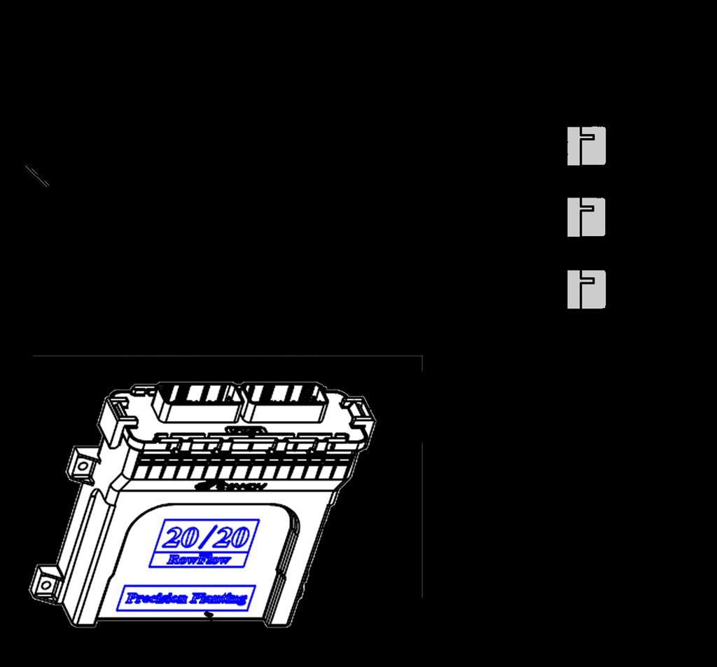
6 System Overview The Row Flow upgrade to the 20/20 SeedSense monitoring system consists of five primary components and harnesses. These parts include; the Row Flow Module, the Cab Control Module, the Mounting Kit, the Base Harness, and a 24 CAN Extension Harness. Row Flow Module Cab Control Module Mounting Kit The Row Flow Module (RFM) contains the processing hardware to communicate with and control planter components and sensors. In addition, the module contains accelerometers to measure and define the forces acting on your planter. The RFM will need to be mounted in a specific manner either laying flat perpendicular or parallel to the direction of travel or with connectors pointing down to guarantee the performance of the accelerometers. The front face of the RFM has two receptacles for connection to the Base Harness. Some larger planters may require a second RFM to be installed. The Cab Control Module (CCM) provides touchpoint controls of the RFM components; hydraulic drives and swath control. Those controls are: Master Plant switch, three individual controls for Hydraulic drive sections, and a Master Swath Control switch. The CCM will be bolted onto the back of the existing 20/20 SeedSense monitor. The rear of the CCM has ports for connecting the existing SeedSense tractor harness, radar input, a remote Master Plant switch, the CAN extension harness, as well as a connector to provide power to GPS receivers. The existing tractor harness will be removed from the rear of SeedSense monitor to be plugged into the CCM. The Mounting Kit will consist of four bolts, eight hex nuts, one mounting plate, and two mounting straps. This should allow multiple variations of mounting the RFM. This will have to be done in a horizontal or vertical stance _02 9/11 6

, a serial output, and an auxiliary power cable.")

7 Base Harness System Overview (Continued) The Base Harness will be the backbone of the Row Flow system and provide the means of connecting power and communication to the various components on the planter. The Base Harness receives power and communication from the display unit and the SeedSense system via the CAN Harnesses from the Cab Control Module. The Base Harness has connections for up to three hydraulic motors, twenty four clutch sections, AUX port, height sensor (s), a serial output, and an auxiliary power cable. 24 CAN Extension Harness The 24 CAN Extension Harness is provided in the base system to deliver power and support communications between the Row Flow Module, the Cab Control Module, and the SeedSense System. The length is designed to reach the hitch point of most tractors. The Extension Harness will connect to the rear of the CCM and should be routed safely to the rear of the tractor, similar to the SeedSense tractor harness. Additional extension harnesses may be required depending on the mounting location of the RFM _02 9/11 7


8 955168_02 9/11 8 System Overview Base Components


9 Mounting the Cab Control Module (CCM) Before mounting the CCM, assemble the mounting bracket to the rear of the module. Secure the base of the bracket to the rear of the CCM using the two supplied X 3/8 hex head screws. Option A Mounting the Cab Control Module using the standard mounting equipment: Begin by removing the monitor from its current location on the mounting bracket. Place the top portion of the CCM mounting bracket between the existing SeedSense mounting bracket and the monitor. Secure all three components in place using the supplied 1/4 X 1/2 GRD5 Hex bolt. Option B Mounting the Cab Control Module using the RAM mounting equipment: Begin by removing the monitor from its current location on the mounting bracket. Place the top portion of the CCM mounting bracket between the existing RAM mounting bracket and the monitor. Secure all three components and tighten the RAM mount. This mounting option will NOT use the supplied 1/4 X 1/2 GRD5 Hex bolt _02 9/11 9
 2 Pin WeatherPack Connector")
 Use the diagram to")

10 9 Pin Amp Connector 4 Pin Amp Connector 16 Pin Amp Connector (Female Coupler) 2 Pin WeatherPack Connector 16 Pin Amp Connector (Male Threaded) Mounting the Cab Control Module (Continued) Use the diagram to correctly connect the cables and harnesses to the rear of the 20/20 Display Unit and Cab Control Module _02 9/11 10

11 Cab Control Module Functionality Master Plant Control Switch Single switch to turn on or off hydraulic drives, this can also be done within the SeedSense Monitor. Master Swath Control Switch Single switch to turn on or off Swath Control functionality, this can also be done within the SeedSense Monitor. Section Plant Control Switches Individual switches to control hydraulic drive motors. These are separated to three momentary switches; Left, Center, and Right. Auto Load The Auto Load functionality on the Cab Control Module will allow the user to initiate the hydraulic drives in one of two modes. This will be accomplished by pushing up on the Left and Right switches simultaneously. Both of these modes will require the tractor to be running, hydraulic flow supplied to the motors, and the vacuum (or pressure) blowers on if applicable. Mode 1: Meter Load By pushing up on the switches and immediately releasing, RowFlow will initiate the hydraulic motors and spin them for 1.5 meter revolutions or until 3 seeds are seen from each meter (whichever comes first). If clutches are installed, RowFlow will clutch individual rows out as they reach 3 seeds and continue to spin the remaining meters for the full 1.5 revolutions. Mode 2: Meter Spin By pushing up on the switches and holding them, Row Flow will spin the meters continuously until the switches are released _02 9/11 11

12 Mounting the Row Flow Module (RFM) Begin this step in the installation process by selecting the mounting location for the RFM. The RFM may be mounted inside the cab, on the hitch or rear of the tractor, and multiple locations on the planter. The selection will be driven by the functions controlled and the connections being made. The majority of systems will locate the RFM at the center rear of the planter main frame or toolbar. This location provides the closest proximity to the abundant cables and connections to be made. Continue below for specific setup instructions; Note Specifications will be described individually for Hydraulic Drives and Swath Control, for systems containing both components RFM placement should be located using your own best judgment for safety and security of the components. (Exception: Serial controlled hydraulic drives require mounting within 15 of drive controller) Hydraulic Drives (variable rate included) Serial Controlled Hydraulic Drives: Rawson, or similar non-pwm controlled, hydraulic motors REQUIRE MOUNTING WITHIN 15 OF THE ACCU RATE CONTROLLER. RowFlow will not communicate directly to Rawson or similar serially controlled hydraulic motors. Communication and control of these motors is accomplished via the Accu Rate (or similar) controller; creating the deciding factor in mounting locations for these systems. Refer to the Connecting to Serial Communications pages for further details. PWM Controlled Hydraulic Drives: When controlling Hydraulic Drive Motors only (non-rawson), RFM mounting will be dependent only on reaching those Hydraulic Drives using the hydraulic motor harnesses and extensions. The hydraulic motor harnesses and extensions are each 15 in length, providing ample flexibility for connections. The RFM can therefore be placed with relative freedom at the center/rear of the planter toolbar. RowFlow systems controlling hydraulic drives ONLY, continue the installation on pages RowFlow systems utilizing swath control continue on the following page _02 9/11 12
13 Mounting the Row Flow Module (RFM) Swath Control Pneumatic Clutches When connecting to Tru Count Air Clutches, the RFM can be mounted anywhere the 6pin Weather Pack connections from the Valve Module Boxes can reach the Base Harness. The Valve Module Boxes from Tru Count normally have 50 of extension to reach from the Valve Module Box mounting location to the controller. This should be sufficient to reach any centrally located RFM mount. Electric Clutches Connecting to electric clutches will be determined by the harnesses present on the planter. If your planter DOES NOT HAVE a clutch control harness; For planters without an existing clutch control harness, controlling the electric clutches will be accomplished by building a new clutch control harness via Precision Planting, Inc. components. The harness will be modular in design; meaning 4 rows will be connected as one harness, then multiple groups of four rows are merged together at the Base Harness to encompass the entire planter. The individual connectors are spaced to encompass row widths up to 38 without extensions. The individual rows are numbered 1 through 4 on the cable as well as on the connectors. In most standard installations, these will be connected ascending from left to right when standing behind the planter (#1 on the left, #4 on the right). Each clutch requires an individual connection to the Clutch Harness and will be independently controlled based upon the Setup & Configuration within the RowFlow settings. The swath sections will be determined within the RowFlow Set-Up, and are counted as the 1st section being the left most section when viewed from behind the planter facing forward. By building the harness using 4 row modules and extensions, we are able to accommodate locating the RFM anywhere reasonably close to the center of the planter. Refer to pages for further information on installation of these systems. If your planter DOES HAVE a clutch control harness; SeedStar2 planter/clutch control harness, Clutch control harness from Ag Leader Connecting to Ag Leader clutch harnesses: Controlling the Ag Leader SureStop and SureVac Clutches will be accomplished by adapting the existing clutch control harness to be compatible with the RowFlow Base Harness. This will mandate that the RFM and Base Harness be mounted in a location within 4 feet of the Molex connector(s) that terminate the Ag Leader clutch harness. Refer to page 31 for further information on installation of these systems. Connecting to John Deere clutch harnesses: For 2009 and newer John Deere planters with the SeedStar 2 planter/clutch harness Controlling the John Deere RowCommand Clutches will be accomplished by adapting the existing clutch control harness to be compatible with the RowFlow Base Harness. This will mandate that the RFM and Base Harness be mounted in a location within 4 feet of the 35 pin or 47 pin Deutsch connector(s) that terminate the clutch portion of the SeedStar2 planter/clutch harness. Refer to page 35 for further information on installation of these systems _02 9/11 13
14 Mounting the Row Flow Module (RFM) Mounting Location Summary: Controlling Rawson Hydraulic Drives (Serial Communications) No YES Option A Mount RFM at Cab or Hitch of Tractor Within 15 of ACCU RATE Controller See Page 28 for more details Option B Centrally Locate RFM on Planter Toolbar Hydraulic Drives Swath Control Clutch Type Pneumatic Harness Mounting Location Tru Count Air Clutch Any Use extensions to accommodate Electric Ag Leader SureStop & SureVac When controlling Hydraulic Drive Motors only (non-rawson), RFM mounting will be dependent only on reaching those Hydraulic Drives and therefore can be placed with relative freedom at the center/rear of the planter toolbar. Existing Clutch Harness Modular Clutch Harness from Precision Planting within 4' of Molex Connector(s) Use extensions to accommodate John Deere Row Command Existing Clutch Harness Modular Clutch Harness from Precision Planting Within 4' of 35pin or 47pin Deutsch Connector(s) Use extensions to accommodate 1/2 Width Disconnects Any Use Extensions to accomodate These mounting options will encompass most RowFlow installations and is directed at all options where the use of the Serial Communications connector is not required. The exact mounting location will vary greatly depending on planter make, model, number of rows, row configuration, as well as any upgrades or modifications from the base planter model. Specific mounting locations can be grouped according to 1.) Clutch Type (Pneumatic vs. Electric) and 2) Existing or Required Harnesses. See pages for more details _02 9/11 14
.")

15 Mounting the Row Flow Module (RFM) Begin this process by securing the RFM to the Mounting Plate (727039). Align the RFM onto the pre-placed studs on the mounting plate. Fix the RFM to the plate using the supplied 10MM Flange Nuts (93298A109). Mounting Kit and Hardware P/N: four - 3/8 X 8 Carriage Bolt (A307ZN) P/N: four - #10 Neoprene Seal Washers P/N: (pre-installed on Mounting Plate) one - Mounting Plate P/N: two - Mounting Straps P/N: four - 3/8 Hex Nut P/N: The mounting location of the RFM will vary based on planter make, model, and other variables. The provided kit will include hardware and brackets to enable mounting the RFM on a variety of bar sizes and locations. Modification of the this hardware or use of custom components may be necessary to encompass individual needs. The primary concerns to keep in mind when mounting the RFM are: 1. Safety-stability of the location, 2. RFM can be oriented according to the restrictions described on page 16, 3. the mounting location will provide adequate access to cables, harnesses, and components on the planter. Note: there are 4 Seal Washers (727051) pre-installed onto the threaded studs on the mounting plate. These washers are intended to absorb the flex and strain of the mounting plate during the installation process without transferring those forces to the RFM. Removal of these washers could result in failure or cracking of the RFM housing. If the RFM must be alternatively mounted, use extreme care not to impart any added stress upon the mounting feet of the RFM housing _02 9/11 15


16 Mounting the Row Flow Module (RFM) Plate and Hex Nuts are part of the kit. The RFM should be mounted so that the entire module is placed within the boundaries of the plate; see example above. Positioning the RFM on the mounting plate as shown at left will provide a secure placement, but will leave the forward face and the ports exposed. For that reason, this placement is not recommended _02 9/11 16

 as a reference.")

17 Mounting the Row Flow Module (RFM) The Row Flow Module contains both accelerometers and a yaw sensor. These sensors give the 20/20 system valuable information about the movement of your planter/tractor combination. To ensure the best performance of these sensors, the RFM will need to be mounted within 5 of level. This process should be done with the planter on a level surface and in the plant position. If it is not possible to unfold the planter at the time of installation, use the main planter frame (toolbar) as a reference. On properly aligned planters this frame will run level to the ground during planting. Verify this setting upon first reaching field operations. We will reference specifically the two 30 terminal Cinch ports on the face of the module. Note: directions based upon viewing location RFM mounted HORIZONTALLY with the 20/20 RowFlow label facing up, choose the direction the two 30 terminal Cinch connector Ports face RFM mounted HORIZONTALLY with the 20/20 RowFlow label facing towards the ground, choose the direction the two 30 terminal Cinch connector Ports face RFM mounted VERTICALLY with the two 30 terminal Cinch ports facing directly towards the ground, choose the direction the 20/20 RowFlow label faces The above screen is located under the RowFlow Setup page. Navigate to this page via: Home Setup Systems RowFlow (under Setup) RFM Direction The RFM should be firmly secured in any direction listed above. To ensure the RFM is mounted within tolerances, a level may be used. Level to less than 1/2 of a bubble or 5 in any direction. A good rule of thumb is: a >5% camber in any direction should be noticeable with the naked eye _02 9/11 17
18 Connecting the Base Harness The Base Harness provides the connection point to the Display Unit/Cab Control Module, RowFlow Module, and all harnesses/components on the planter. The following list is a quick reference guide to the Base Harness connections. Detailed images of the Base Harness and descriptions of its connection points are provided on the following pages. The two - 30 pin Cinch plugs will plug directly into the face of the RFM. Use caution when connecting these points not to damage the connecting pins within the RFM. Use the embedded screws to secure the plugs into place (torque to NO GREATER than hand tight + 1/4 turn). Connect the Labeled/Fused Cinch plug to the Left port on the RFM face when upright and towards the harness - see page 19 for more details. The Y at the end of the 6 extension allows connection forward to the monitor/ CCM as well as to secondary RowFlow Modules (if present). The Serial Connector will be utilized only when controlling Rawson Hydraulic Drives. See pages for more details. The Auxiliary Power connection should be connected in all standard situations (as shown opposite). This is the power source when drawing power and communication from the CAN harness. When greater than 7 amps is required, disconnect this point and reconnect the receptacle to the Tractor Power Harness or extension. See pages for more details. The 6 pin WeatherPack connectors enable output to swath control devices. Care should be taken to ensure swath sections are connected properly (section numbering commonly begins with 1 being the LEFT most row when standing behind the planter facing forward). Exact Swath Section location may be adjusted within the 20/20 monitor. These connections may require adapters. See pages for more details. The 8 pin Deutsch connectors enable output to hydraulic drive motors for variable rate. (Motor numbering begins with 1 being the LEFT most motor when standing behind the planter facing forward). See pages for more details. The Height Sensor connection will need to be made to the extension harness from the installed implement switch, whisker switch, or pair of row unit lift switches. It is best if these are located on the center frame section of the planter. See pages for more details. Once all connections have been made, properly secure those and all remaining wires to prevent damage _02 9/11 18
 6 pin WeatherPack Connectors")


19 CAN (Input - used only with Second RFM) CAN (Output to CCM) 6 pin WeatherPack Connectors Output to Swath Control pgs RowFlow Module DB9 Serial Connector (Rawson Drives Only) pgs p Deutsch To Hydraulic Drives pgs CAN Power Power Input Height Sensor pgs _02 9/11 19


20 Connecting the Base Harness to the RFM The two - 30 pin Cinch connectors on the Base harness will connect directly to the RowFlow Module. The RowFlow Module is the primary throughput for information from and commands to the planter from the 20/20 SeedSense Monitor and RowFlow software. To ensure this connection is made correctly, both the RFM and Base Harness have corresponding markers that should line up when installed. Note the location of the RFM serial number. This number can also be found within the SeedSense monitor under the Device Status page. This number may be referenced during troubleshooting, technical bulletins, and recall information _02 9/11 20


21 Connecting Power The Standard CAN Harness is capable of providing communications and power up to 7 amps of draw. This will encompass most systems and is the default design. In this configuration the two - 2 pin WeatherPack connectors on the Base Harness will be connected, providing a completed circuit. If greater than 7 amps is required, this circuit can be disconnected to allow connection to a circuit capable of supplying the maximum draw of 18 amps per RFM. The diagram on the following page illustrates how we will build the circuit. To determine the amperage draw of your system use the following equation: Component Current Draw (amps per component) # of Components to be controlled on your planter Component Subtotal Hydraulic Drive Motor 1 X = Tru Count Valve Box 2 X = Electric Clutches 0.5 X = + Grand Total = If your Grand Total is > 7 Amps or you are connecting to high output section solenoids (1/2 width disconnects); Continue below to supply adequate current to the system. If your Grand Total is <7 Amps; Ensure a solid connection between the CAN Power and Aux Power, and move on to connecting the height sensor. Providing the current required by the RFM can be provided using different harnesses: John Deere planters with SeedStar 2 planter harnesses have an MX connector capable of supplying the required current. This connector will be centrally located at the rear of the planter, usually within close proximity to the wedge box. The MX Power Splitter ( ) adapts this connector to make connection possible with the RowFlow Base Harness. MX Power Splitter ( ) _02 9/11 21


22 Base Harness Connecting Auxiliary Power The majority of systems requiring additional current will provide that power by connecting directly to the power source of the tractor. The Tractor Power Harness Kit will connect to the Battery or Starter posts to provide direct access to the electrical source via a heavy duty cable. AirForce owners currently using a 12V compressor will have this harness previously installed and will need to temporarily disconnect these cables. The Planter Power Extension Harness connects to the Tractor Power Harness to distribute power to the planter. The AirForce harness can then be re-connected to continue to provide power to the AirForce system. Multiple lengths of the Planter Power Ext. Harness are available and are listed below. A 25-2pin WeatherPack Extension (727126) is also available to extend this connection Planter Power Extension Harness Available lengths: _02 9/11 22

: Ground Drive or contact drive systems inherently stop the meters from turning while the planter is raised.")
23 Connecting to Height Sensor(s) RowFlow systems controlling swath functionality only: RowFlow systems controlling swath control functionality only do not require a height sensor and may skip this portion of the installation. Frame position information will have no bearing on the functionality of the swath system. Swath functionality is determined by location within the field and designation of that location with the field (plant, do not plant, and planted). RowFlow systems controlling hydraulic drives (with or without swath functionality): Ground Drive or contact drive systems inherently stop the meters from turning while the planter is raised. Simply, as the planter frame rises, the drive tire loses contact with its transport tire, stopping the hex shaft rotation. Hydraulic drives lack the inherent link to planter frame position that a ground drive planter has. To supply planter frame position information to the RowFlow system, some form of height sensor must be installed. The Height Sensor is a simple switch component that can be mounted on either the planter frame or onto individual row units. Independent of the height sensor style, the sensor/switch should be mounted on the center frame or center section of the planter to remove the variability experienced by the wings of the planter. The Height Sensor harness will need to be routed safely and securely to this connection point on the Base Harness. Base Harness Frame or Row-Unit mounted height sensors: The type of height sensor used will be dependent on user preference, mounting location, clearance or access to the proper components, as well as other factors. Of primary concern is a solid, stable signal that is accurate with the true position of the planter. Only one frame-mounted height sensor will be required however, two row-unit mounted height sensors are required. By placing the switch on the row unit, the possibility exists for the individual row unit to drop (replicating a lifted situation, thereby stopping the hydraulic drives) while the planter is still in a lowered position. This situation is averted by connecting two lift switches on the same circuit. Both switches must register a lifted position, before the system will stop the hydraulic drives; conversely, only one of the two switches needs to register lowered to enable the hydraulic drives. One or both of the Lift Switches should be installed on the center frame section of the planter for greatest stability. Both styles, frame and row-unit mounted, are perfectly functional and can provide stable accurate information to the RowFlow system. Understanding the differences and characteristics of the height sensor you will be using will help ensure the most accurate and consistent performance _02 9/11 23

; only one additional Lift Switch and the Lift Switch Harness will")


 Motor Configuration")

24 Row Unit Mounted Lift Switches As noted, when using Row Unit Lift Switches, two switches will be required. If you are currently using an AirForce system utilizing a Lift Switch plugged into a Row Unit Module (RUM); only one additional Lift Switch and the Lift Switch Harness will be needed. Disconnect the existing Lift Switch from the RUM and re-connect both switches into the Switch Harness. The Lift Switch Harness will connect into the Base Harness. The AirForce system WILL NOT receive the signal from the lift switch until it has been properly calibrated within the RFM. Verify the Lift Switch has been properly calibrated within the SeedSense monitor to ensure the signal is correct AND shared with the AirForce systems. Navigation: Home Setup Systems RowFlow icon (under Setup portion) Motor Configuration Lift Switch Lift Switch Harness To Base Harness Available Lift Switches with compatible planter Models JD 7200/1700 Regular Parallel Arms JD 7200/1700 Long Parallel Arms JD 7000/ Kinze CNH, White White Great Plains Mounted Lift Switch Examples Great Plains JD 72XX & 17XX 14 parallel arms _02 9/11 24 JD 72XX & 17XX 21 parallel arms Kinze & JD 7000


 John Deere Rotary Height Sensor Y Harness - (727168) CNH Rotary Height Sensor Y Harness - (727171) 15 Height Switch Extension - (727116) Note:")
25 Frame Mounted Height Sensors Only one of these sensors will be required per planter. Frame Mounted Height Sensors are not susceptible to the same situations that require two row lift switches. These sensors are mounted directly to the frame and give an accurate location of the frame independent of the movement of the row units. Rotary Height Sensors For John Deere & CNH planters with factory installed hydraulic drives, a Rotary Height Sensor should be present. This component may be present on non hydraulic drive planters as well. It is also available from your local John Deere dealer for aftermarket field installations. This sensor will be mounted directly to the frame and one of the carriage wheels of the planter as shown. If installing this component yourself, be sure to install this on the center frame section of the planter. Connection from this sensor to the RowFlow module will be done via a Rotary Height Sensor Harness (see harness options below) from Precision Planting. This harness will replace the existing cable, connecting into the sensor as shown by the arrow in the image. For systems requiring the original harness stay connected, a Y harness is available to split the sensor information to multiple systems. 9 John Deere Rotary Height Sensor Harness - (727178) John Deere Rotary Height Sensor Y Harness - (727168) CNH Rotary Height Sensor Y Harness - (727171) 15 Height Switch Extension - (727116) Note: Systems prior to RFM serial number include a voltage regulator on the base harness in line with the height sensor connector. This Height Sensor Voltage Regulator Harness (727042) should be left intact when used with the John Deere Rotary Height sensor (Precision Planting Harnesses or ). The purpose of this regulator is to normalize the voltage to the height sensor, thereby minimizing the impact of intermittent voltage dips and spikes on height sensor performance. Subsequent RFM models have this regulator functionality embedded internally Rotary Height Sensor Voltage Regulator Whisker Switches Whisker Switch with 9 Harness - (727123) 15 Height Switch Extension - (727116) Whisker Switches, like rotary sensors, are mounted directly to the frame and articulated by the movement of a lift dependent component of the planter. These sensors are utilized when standard mounting positions and sensors is not possible. A standard mounting kit is included for the Whisker switch including a ceramic coated magnet, screws as well as 9 of harness. Fix the switch component to the provided magnet using the four supplied M6 screws. Use the magnet to position the whisker switch assembly to the planter. Using a magnet allows much greater flexibility in the mounting points and ease of adjustability. Align the rod portion of the Whisker Switch with some component that will actuate the rod as the planter raises and lowers. Other common installation means make use of the four mounting holes on the housing of the switch itself in conjunction with custom drilled holes on the planter or custom mounting brackets. Extreme care should be taken to ensure accurate readings prior to drilling these mount points _02 9/11 25
26 Connecting to Hydraulic Drive(s) The Base Harness is outfitted with three - 8 pin Deutsch connectors (labeled Drive 1, 2 or 3) to enable power and communication with up to 3 hydraulic drive motors. This connection method will offer full functionality and diagnostics when connecting to drives purchased from Precision Planting as well as when connecting to existing drives from John Deere, Kinze, White, CNH, Great Plains, and Dickey John. The RowFlow system can use BOTH measured output shaft speed AND incoming hydraulic pressure sensors. This will enable greater detail in diagnosing/trouble-shooting errors and calibration of the system. Hydraulic Drives purchased from Precision Planting will have the incoming hydraulic pressure sensors pre-installed. All other modifications of existing drives will include the appropriate pressure sensor along with the Hydraulic Motor harness Notes: Veris Planters adapting Veris hydraulic drives should install the Speed Sensor Adapter. CNH Use CNH Hydraulic Motor Harness ( equivalent) 12R30 and 16R30 planters: Precision Planting does not recommend using the OEM hydraulic motors (factory or field installed). The standard on CNH planters is to group all of the control solenoids on one primary manifold to control planter hydraulics. This separates the control solenoid from the hydraulic motor by some linear distance. The addition of this in-line distance from the point of hydraulic flow control to the point of use, the motor, results in inconsistent motor performance. A common symptom of this is a slight jerking or loping of the drives displayed in erratic seed placement. To resolve this issue, these should be replaced with Precision Planting motors with separate hydraulic lines. Dickey John, Great Plains, Kinze, & White For Kinze, Great Plains, and all planters using Dickey John hydraulic motors, an additional hydraulic fitting will be required to complete this installation. The chart below provides part numbers and description for ordering the appropriate fittings. Access to the hydraulic system for pressure measurements will be made in line with the hoses using these diagnostic tees. The #6 ORB to #4 ORB adapter will not be required in this installation. PART NUMBER A B C DESCRIPTION JIC -6 DIAGNOSTIC TEE (3/8 ) JIC -8 DIAGNOSTIC TEE (1/2 ) JIC -10 DIAGNOSTIC TEE (5/8 ) JIC -12 DIAGNOSTIC TEE (3/4 ) Kinze & White: Use Deutsch Valve Connector Adapter (727127) for compatibility with these motors and Hydraulic Motor Harness To Harness To Harness To Control Valve Solenoid Great Plains & Dickey John: Use WeatherPack Valve Connector Adapter (727128) for compatibility with these motors and Hydraulic Motor Harness To Control Valve Solenoid _02 9/11 26


")


27 John Deere For standard John Deere planters with factory installed OEM hydraulic drives, all components needed for installation are included within the kit. Remove the plug on the side of the control manifold and replace with the #6 ORB to #4 ORB adapter. Install the Pressure Sensor (727007) into the adapter and connect the harness to complete the installation. The Hydraulic Motor Harness will connect directly to the OEM speed sensor Base Harness #6 ORB to #4 ORB Adapter Hydraulic Pressure Sensor 15-8 Pin Deutsch Extension cables are available to augment the existing 15 Hydraulic Motor Harness _02 9/11 27


 to the ACCU-RATE This mounting option will necessitate routing of all planter tool bar component")

28 Connecting to Serial Communications Rawson Hydraulic Drives ONLY Use of the Serial Communications cable on the Base Harness will be for systems adapting existing or new Rawson Hydraulic Drives. This information also applies to the necessary mounting location of the RFM This option will refer to planters adapting control of Rawson Hydraulic Drives. The 20/20 RowFlow will not communicate directly with these motors. Automation of the hydraulic motors will be done VIA the ACCU-RATE Variable Controller. This will be done by connecting DB9 serial connector from the Base Harness to the serial port on the ACCU-RATE Variable Controller. The constraints of Serial communication require communication travel paths less than 15 in length. This will require the RFM and Base Harness to be placed so as to allow safe routing of the serial extension (6 or 15 available) to the ACCU-RATE Variable Controller. This mounting option will necessitate routing of all planter tool bar component harnesses (Swath control harnesses, lift switch harnesses, etc ) to the RFM mounting location to connect into the Base Harness. Rawson ACCU-RATE Controller This controller is not provided by Precision Planting DB9 Serial Port Connect Serial extensions to this port on the rear of the controller DB9 Serial Connector Base Harness DB9 Serial Extension Cables 6 extension extension _02 9/11 28
29 Rawson Accu-Rate Setup The goal is to get both LED s on the Rawson Accu-Rate Controller green and the population on the Rawson controller to match the population on the 20/20. Troubleshooting: Verify Rawson Setup is complete and accurate. See diagram on following page. Verify Serial Drives are configured via RowFlow Setup within SeedSense. Verify MASTER PLANT Switch on Cab Control Module is in PLANT position. Check OFF/RUN/ROTATE Switch on Rawson. Switch must be in Run (middle position). Check LEFT OFF/RUN/RIGHT OFF Switch on Rawson. Switch must be in Run (middle position). Check Lift Switch. A Lift Switch is NOT mandatory on this system. The Rawson Accu-Rate system does not require a Lift Switch (can be operated via incab toggle switch). However, if a Lift Switch is installed, the planter MUST be lowered. When connected to a serial drive, the 20/20 RowFlow controls WILL NOT require a lift switch. If the Lift Switch remains un-calibrated within RowFlow Setup, the system will assume that this functionality is provided within the Rawson system. If the Lift Switch is configured within RowFlow, it MUST be calibrated and in the lowered position. If the Lift Switch is UNCALIBRATED, the sensor information will be ignored. If the Lift Switch is CALIBRATED, it will shut off the Rawson when raised. Verify Population command being sent to the Accu-Rate controller from RowFlow. This can be viewed on the RowFlow Diagnostic page under Serial Out; Motor 1 and Motor 2. Auto-Load functionality from the 20/20 Cab Control Module will NOT rotate the Rawson Drives. To perform this action, use the Rawson OFF/RUN/ROTATE switch. Push to ROTATE to spin drives while standing still _02 9/11 29
30 ACCU-RATE FLOW CHART CALIBRATION MODE ACCU-RATE 9.1XX SET FIELD OPERATION START FIELD OPERATION Continue here from similarly marked Point A under Setup Product B column SETUP PRODUCT A SETUP PRODUCT B START CALIBRATION PLANTING MODE DISABLED PLANTING MODE A NON GPS MODE GPS MODE NON GPS GPS FIXED RATE MAN. SPD 5.0 OFF MAN. SPD 5.0 ON < COM A COM B > NUMBER OF ROWS = 12 BIT 7 MODE: OFF BIT 7 MODE: ON ROW WIDTH = 30.0" STEPS SEEDS/ACRE = 0,028,000 2% 4% 6 2/3% CALIBRATE? THESE VALUES MUST MATCH BASE POPULTATION & STEP % IN ROWFLOW SETUP, MOTOR DISPENSING SEEDS CONFIGURATION A Continue at similarly marked Point A under Setup Product A column to left # OF SEEDS = 020 CAL. FEET = 400 Note: Set manual speed value to 3.0mph to read seed data while not moving MAN. SPEED = 5.0 TEST FEET = 174 ACTUAL FEET = 174 RUN 174 FEET? MOTOR RUNNING SAVE PRESETS YES SAVE PRESETS NO PRESETS SAVED NOT SAVED PROG. MODE OFF PROG. MODE ON READY TO REPROG. CALIBRATION MODE ENDS..GOES INTO FIELD OPERATION MODE _02 9/11 30


31 Connecting to Swath Control Pneumatic Clutches When connecting to Tru Count Air Clutches, the RFM can be mounted anywhere the 6pin Weather Pack connections from the Valve Module Boxes can reach the Base Harness. The Valve Module Boxes from Tru Count normally have 50 of extension to reach from the Valve Module Box mounting location to the controller. This should be sufficient to reach any centrally located RFM mount. These components NOT provided by Precision Planting Tru Count Air Clutch Use caution when connecting these extensions into the RowFlow Base Harness to ensure the correct placement of swath sections. Swath sections are counted as the 1st section is the left most when viewed from behind the planter facing forward. Each Valve Module box represents 4 sections. The numbers on the box represent those four sections within that box; thereby on the second Valve Module box, those numbers would refer to sections 5-8, not sections 1-4. Use extension harness for connection to Base Harness Base Harness _02 9/11 31


32 Connecting to Swath Control (Continued) Electric Clutches Connecting to electric clutches will be determined by the harnesses present on the planter. If your planter DOES HAVE a clutch control harness, SeedStar2 planter/clutch control harness, Clutch control harness from Ag Leader, proceed to page 34. If your planter DOES NOT HAVE a clutch control harness, continue below. For planters without an existing clutch control harness, controlling the Ag Leader SureStop and SureVac Clutches will be accomplished by building a new clutch control harness via Precision Planting, Inc. components. The harness will be modular in design; meaning 4 rows will be connected as one harness, then multiple groups are merged together at the Base Harness to encompass the entire planter. Each row will be independently controlled based upon the Setup & Configuration within the RowFlow settings. By building the harness in this fashion we are able to accommodate locating the RFM anywhere reasonably close to the center of the planter. The primary components of this system are given below. Ag Leader SureStop Clutch Connect to Base Harness or Ext. Harness The individual connectors are spaced to encompass row widths up to 38 without extensions. The individual rows are numbered 1 through 4 on the cable as well as on the connectors. In most standard installations, these will be connected ascending from left to right when standing behind the planter (#1 on the left, #4 on the right). Swath sections will be determined within the RowFlow Set-Up 4 Row Clutch Harness (727135) Connect directly to the clutch at row unit Use these extensions as necessary to connect the 4 Row Clutch harness to the Base Harness. 15 Individual Row Extension Harness (727144) These are available to enable connection to individual rows from the Clutch Harness when greater than 38 Row Spacing or around fold/transport points _02 9/11 32


33 Connecting to Swath Control (Continued) For planters without an existing clutch control harness, controlling the John Deere RowCommand Clutches will be accomplished by building a new clutch control harness via Precision Planting, Inc. components. The harness will be modular in design; meaning 4 rows will be grouped together at a time, then multiple groups merged together at the Base Harness to encompass the entire planter. By building the harness in this fashion we are able to accommodate locating the RFM anywhere reasonably close to the center of the planter. The primary components of this system are given below. John Deere Row Command Pro-Series Clutch The individual connectors are spaced to encompass row widths up to 38 without extensions. The individual rows are numbered 1 through 4 on the cable as well as on the connectors. In most standard installations, these will be connected ascending from left to right when standing behind the planter (#1 on the left, #4 on the right). Each clutch requires an individual connection to the Clutch Harness Connect to Base Harness 4 Row Clutch Harness (727134) Connect directly to the clutch at row unit The swath sections will be determined within the RowFlow Set-Up, and are counted as the 1st section is the left most section when viewed from behind the planter facing forward. Use these extensions as necessary to connect the 4 Row Clutch module to the Base Harness when the clutch harness is placed beyond 12 from the RFM/Base Harness mounting location. 15 Individual Row Extension Harness (727145) These are available to enable connection to individual rows from the Clutch Harness when greater than 38 Row Spacing or around fold/transport points _02 9/11 33

 The 727118 - Adapter Harness will connect into Ag Leader s Section Adapter Cables.")
34 1-4 Base Harness Connecting to Swath Control (Continued) 16 pin Molex Connector 2 pin Deutsch Connector 6 pin WeatherPack Connectors Controlling the Ag Leader SureStop Clutches will be accomplished by adapting the existing clutch control harness to be compatible with the RowFlow Base Harness. This will mandate that the RFM and Base Harness be mounted in a location within 4 feet of the Molex connector(s) that terminate the Ag Leader clutch harness. Ag Leader SeedCommand Adapter Harness (727118) The Adapter Harness will connect into Ag Leader s Section Adapter Cables. One Adapter Harness will be required for each Ag Leader Module present on the planter. The table provides the Section Adapter Cable part number (from Ag Leader) and the corresponding number of Precision Planting Adapter Harnesses to accurately link the RowFlow system to the existing clutch control harness. This has to do with the number of rows per section. In an Ag Leader system, this determination is accomplished via the Section Adapter Cable in the basic Ag Leader installation. Once installed these cables FIX the minimum number of rows per section. Modification of the minimum number of rows/section after installation of the Ag Leader harness is possible only by replacing the Section Adapter Cables. To existing clutch control harness AgLeader Section Adapter Cable Part # Precision Planting Number of SeedCommand Adapter Harnesses (727118) required Ground (-) supply to Clutch Harness To Base Harness _02 9/11 34


35 Connecting to Swath Control (Continued) For 2009 and newer John Deere planters with the SeedStar 2 planter/clutch harness Controlling the John Deere RowCommand Clutches will be accomplished by adapting the existing clutch control harness to be compatible with the RowFlow Base Harness. This will mandate that the RFM and Base Harness be mounted in a location within 4 feet of the 35 pin or 47 pin Deutsch connector(s) that terminate the clutch portion of the SeedStar2 planter/clutch harness. 35 pin or 47 pin Deutsch Connector (connect to SeedStar2 harness) 6 pin WeatherPack Connectors (connect to Base Harness) John Deere RowCommand Adapter Harness (727117) The SeedStar2 planter harness will control up to 32 rows. The JD RowCommand Adapter Harness will make the connection from this harness to the RowFlow Base Harness possible. Note: If controlling greater than 24 swath sections, sections will be routed to the 2nd RFM. Base Harness Connect to 2nd RFM Base Harness If the clutches have/are being field installed (modified from factory settings), an additional harness will be required to adapt the SeedStar2 harness to communicate with both seed sensors and clutches. One will be needed for each row _02 9/11 35
36 Notes _02 9/11 36
DeltaForce System Operation
 DeltaForce System Operation 955294 1 1/2014 Index Precision Planting Warranty and Liability.Page 3 Safety Information Page 4 System Requirements.Page 5 Frequently Asked Questions..Page 6 Hydraulic Fittings..Page
Clutch Control. PN: November 2013 Rev E 1
 NOTE: Indented items indicate parts included in an assembly listed above Part Name/Description Part Number Quantity Module Kit 4100533 1 Cable Installation Kit 2000901-1 1 Alcohol swab packet 2002811 2
YieldSense CNH Installation Guide
 YieldSense CNH Installation Guide 9/2013 1 955521 Precision Plan ng, LLC 23207 Townline Road Tremont, IL 61568 ph. (309) 925-5050 fax. (309) 925-5029 info@precisionplan ng.com 2020support@precisionplan
Reference Manual /12
 DrillMaster Planter Drive Controller Reference Manual 612366-03/12 Table of Contents Description of Operation, Safety and Care.............. 1 Installation.................................... 2-3 Tractor
Planting. Press to Highlight Configuration. Gauge Wheel Load Alarm. Value must be entered for your specific planter and parallel arm combination
 To create a configuration, make the following button presses to start the Configuration Wizard and then follow the instructions given on the display. Planting Start of Configuration Wizard Enter Settings
ISOBUS Down Force Hydraulics Kinze
 Important Notices Please carefully follow these step-by-step instructions. If you have questions, contact at 515-232-5363 x 1. Direction words (LEFT and RIGHT) are commonly used when describing an installation
RAM Rail Mount Kit RAM 201UD 5 Arm RAM 2461U Base RAM 235U Base, Double U-Bolt
 Note: Indented items indicate parts included in an assembly listed above. Part Name/Description Part Number Quantity Direct Command Kit 4100514 1 Installation Instructions 2005690 1 CAN Y-Splice 4000137
GPS AutoSteer System Installation Manual
 GPS AutoSteer System Installation Manual Supported Vehicles Case IH Combines 7010 7120 8010 8120 AFX 8010 9120 PN: 602-0283-01-A LEGAL DISCLAIMER Note: Read and follow ALL instructions in this manual carefully
Quick Setup Guide for IntelliAg Model YP Air Pro
 STEP 1: Pre-Programming Preparation: The Quick Guide assumes the Virtual Terminal, Master Switch, Working Set Master, Working Set Member, and all sensors have been connected and properly installed. Reference
Endeavor Fertilizer Controler" Electric Pump Fertilizer System for John Deere GS2 with Servo Control
 Endeavor Fertilizer Controler" Electric Pump Fertilizer System for John Deere GS with Servo Control We Can Also Interface with These Popular Third Party Controllers: Trimble - EZ Boom & Field IQ Ag Leader
Quick Setup Guide for IntelliAg Model YP40 20 Air Pro
 STEP 1: Pre-Programming Preparation: The Quick Guide assumes the Virtual Terminal, Master Switch, Working Set Master, Working Set Member, and all sensors have been connected and properly installed. Reference
GPS AutoSteer System Installation Manual
 GPS AutoSteer System Installation Manual John Deere Track Supported Models 8295RT 8320RT 8345RT PN: 602-0255-01-A LEGAL DISCLAIMER Note: Read and follow ALL instructions in this manual carefully before
Quick Setup Guide for IntelliAg Model 3PYP 12 Row Single Row Air Pro
 STEP 1: Pre-Programming Preparation: Power on vehicle via ignition switch to activate Virtual Terminal (VT). Main menu will display pre-programmed default settings. If errors are detected (e.g., failed
General Information. Notations and Conventions. Compatibility Check. Kit Description. Call-Outs. Part Lists Great Plains Manufacturing, Inc.
 Part Lists Great Plains Manufacturing, Inc. 1 Installation Instructions Loup Shaft Monitor Used with Drill models: Compatible with most 1995 and later, two- and three-box drills with 5 8 -inch square main
Front-Fold Planters All Makes & Models
 Front-Fold Planters All Makes & Models Row by Row Down Force Master Kit PN: 2006442-ENG REV. C Introduction Important Information This guide provides the basic information needed to install the Ag Leader
GPS AutoSteer System Installation Manual
 GPS AutoSteer System Installation Manual John Deere MFWD Valve Install Vehicles Supported Models 7200 7210 7400 7410 7600 7510 7700 7610 7800 7710 7810 PN: 602-0212-01-A LEGAL DISCLAIMER Note: Read and
GPS AutoSteer System Installation Manual
 GPS AutoSteer System Installation Manual Supported Vehicles Agco Gleaner Combines R65 R66 R75 R76 PN: 602-0288-01-A LEGAL DISCLAIMER Note: Read and follow ALL instructions in this manual carefully before
ROW PRO DOWN PRESSURE
 Operator s Manual ROW PRO DOWN PRESSURE VERSION 2 & 3 Safety Notices... 1 Disclaimer... 1 Row-Pro Down Pressure... 3 Requirements... 3 Setup... 4 Control Mode... 4 Disable Down Pressure Modules... 7 Setting
GPS AutoSteer System Installation Manual
 GPS AutoSteer System Installation Manual Supported Vehicles John Deere Sprayers 4700 4710 4720 Non-AutoTrac Ready PN: 602-0228-01-A LEGAL DISCLAIMER Note: Read and follow ALL instructions in this manual
2-row and All-row systems included.
 Ag Leader Technology Cotton Picker Installation Installation Instructions for John Deere cotton picker models: 2-row and All-row systems included. IMPORTANT: Ensure the model numbers shown above correspond
Ag Leader Technology InSight/Ag Leader Integra. OptRx OptRx Remote Sensor Kit
 : Indented items indicate parts included in an assembly listed above Part Name/Description Part Number Quantity Master Module Kit 4100804 1 Master Module 4001821 1 Cable - Master 4001904-10 1 Cable - CAN
GPS AutoSteer System Installation Manual
 GPS AutoSteer System Installation Manual Supported Vehicles Case IH Vehicles Case 2577 Combines Case 2588 Combines Accuguide Ready PN: 602-0233-01-A LEGAL DISCLAIMER Note: Read and follow ALL instructions
General Information. Assembly Instructions B L R F. 3000TM Fold Assist Kit
 Fold Assist Great Plains Manufacturing, Inc. 000TM Fold Assist Kit General Information These Instructions explain how to install the fold assist kit update. This update only applies to the 000 Turbo Max.
AEROMOTIVE Part # HP Hot Rod EFI Kit INSTALLATION INSTRUCTIONS
 AEROMOTIVE Part # 17150 700HP Hot Rod EFI Kit INSTALLATION INSTRUCTIONS CAUTION: Installation of this product requires detailed knowledge of automotive systems and repair procedures. We recommend that
FLEXI-COIL 67 Series (1999+) Installation Manual FC1
 Installation Manual FC1") FC1 FLEXI-COIL 67 Series (1999+) Installation Manual Printed in Canada Copyright 2012 by NORAC Systems International Inc. Reorder P/N: UC4.5-BC-FC1-INST Rev C (FLEXI-COIL 67 Series (1999+)) NOTICE: NORAC
FC1 FLEXI-COIL 67 Series (1999+) Installation Manual Printed in Canada Copyright 2012 by NORAC Systems International Inc. Reorder P/N: UC4.5-BC-FC1-INST Rev C (FLEXI-COIL 67 Series (1999+)) NOTICE: NORAC
Wing-Fold Planters All Makes & Models
 Wing-Fold Planters All Makes & Models Row by Row Down Force Master Kit PN: 2006444-ENG REV. C Introduction Important Information This guide provides the basic information needed to install the Ag Leader
SureFire Drives and Harnesses for use with John Deere Dry Rate Controller
 396-001640 SureFire Drives and Harnesses for use with John Deere Dry Rate Controller & SureFire Dry Fertilizer Control Components 396-001640 John Deere Rate Controller Dry Instructions Page 1 02/23/2012
PN: A. Reactive Steering Kit Installation Manual
 PN: 602-0275-01-A Reactive Steering Kit Installation Manual LEGAL DISCLAIMER Note: Read and follow ALL instructions in this manual carefully before installing or operating the AutoSteer system. Note: Take
Sprayer Control. Manual for SprayLink Cable Installations. Tank. Jet Agitator. Agitator Valve. Diaphragm Pump. Pressure Transducer.
 Sprayer Control Plumbing & Installation Manual for SprayLink Cable Installations Tank Jet Tank Shut-Off Diaphragm Pump Electric Ball s Transducer Strainer Relief Regulating Copyrights 2012 TeeJet Technologies.
GPS AutoSteer System Installation Manual
 GPS AutoSteer System Installation Manual John Deere MFWD AutoTrac Ready Supported Models 8225R 8245R 8270R 8295R 8320R 8345R PN: 602-0254-01-A LEGAL DISCLAIMER Note: Read and follow ALL instructions in
GPS AutoSteer System Installation Manual
 GPS AutoSteer System Installation Manual Supported Vehicles Case STX Wheeled or Quadtrack Case STEIGER Wheeled or Quadtrack New Holland TJ New Holland T 380 380 380 9030 430 385 430 9040 480 430 480 9050
INSTALLATION MANUAL - v4
 I-LOCKTM COUPLER INSTALLATION MANUAL - v4 SPECIAL NOTE Your new Wedgelock Coupler fitted with the I-LOCK TM Safety Device requires the installation of a third hydraulic line - please follow the instructions
Installation Guide CLAAS Lexion Combines with 9 inch Elevators
 Installation Guide CLAAS Lexion Combines with 9 inch Elevators 955614_01 4/17 1 Table of Contents System Overview 3 Quick Start Guide 4 Flow Sensor Installation 5 Hydraulic Elevator Adjustment Kit Installation
& PumpRight for PWM Control. Maximum Pump Flow and Application Rates. Max Flow GPM
 396-001070 PumpRight Fertilizer System for John Deere GS2 2600 & GS3 2630 & PumpRight for PWM Control Maximum Pump Flow and Application Rates Number of Diaphragms Max Flow GPM Max GPA on 40 at 6 MPH Max
Display Quick Reference Guide
 Display Quick Reference Setup Summary Universal Terminal Camera Operating Configuration Selection Tillage Planting Application Harvest Water Management Guidance Case IH MX 290, 24r Equipment Name Vehicle
Instructions for 2-row monitoring only
 Installation Instructions for CaseIH cotton picker models: Instructions for 2-row monitoring only Ensure the model numbers shown above correspond to the machine model. If you receive the incorrect installation
SAC Liquid Manure Flow Meter
 LM300000 REV A 11/11/2009 QUALITY PEOPLE, QUALITY PRODUCTS SAC Liquid Manure Flow Meter Operation and Service Manual ASSEMBLY CALIBRATION OPERATION REPLACEMENT PARTS READ complete manual CAREFULLY BEFORE
GPS AutoSteer System Installation Manual
 GPS AutoSteer System Installation Manual Supported Vehicles Case IH Vehicles Case 5088 Combines Case 6088 Combines Case 7088 Combines Accuguide Ready PN: 602-0250-01-A LEGAL DISCLAIMER Note: Read and follow
Installation. Manual. OnTrac2+ GPS Assisted Steering System PN: A
 Installation OnTrac2+ GPS Assisted Steering System Manual PN: 602-0208-02-A Copyright Copyright 2012. All rights reserved. This document is copyrighted and all rights are reserved. Information in this
Seed-Squirter. Installation Guide. APPLICATION SYSTEMS FOR PROFESSIONALS. How Can We Help?
 Installation Guide APPLICATION SYSTEMS FOR PROFESSIONALS TM www.capstanag.com How Can We Help? 855-628-7722 prodsupport@capstanag.com P/N 115700-007 Rev. A Revised 02/2018 2018 Capstan Ag Systems, Inc.
Quick Setup Guide for IntelliAg Model YP
 STEP 1: Pre-Programming Preparation: Power on vehicle via ignition switch to activate Virtual Terminal (VT). Main menu will display pre-programmed default settings. If errs are detected (e.g., failed senss,
Rostselmash Torum 740
 Note: Indented items indicate parts included in an assembly listed above Quantity by Model Part Name/Description Part Number 740 Combine Kit Torum 740 4100762 1 Threaded Arm Assembly 2000311-2 1 Header
GPS Steering System Installation Manual
 GPS Steering System Installation Manual Supported Vehicles Challenger Massey Ferguson AGCO MT-645C, MT-645D MF-8650 DT-205B MT-655C, MT-655D MF-8660 DT-225B MT-665C, MT-665D MF-8670 DT-250B MT-675C, MT-675D
AgXcel GX5 Install Guide for Integration into Trimble. where precision meets the soil... PO Box 1611 Kearney, NE
 where precision meets the soil... AgXcel GX5 Install Guide for Integration into Trimble PO Box 1611 Kearney, NE 68848 877.218.1981 www.agxcel.com where precision meets the soil... AgXcel Integration into
Automated Steering Hydraulic Installation Kit
 Automated Steering Hydraulic Installation Kit P/N: ED-JD7010 its John Deere Tractor odels: 7200 7210 7400 7410 7510 7600 7610 7700 7710 7800 7810 Overview A series of equipment specific hydraulic installation
Quick Setup Guide for IntelliAg Model YP Twin Row
 STEP 1: Pre-Programming Preparation: The Quick Guide assumes the Virtual Terminal, Master Switch, Wking Set Master, Wking Set Member, and all senss have been connected and properly installed. Reference
PFadvantage JD 3300/4400/6600/7700; 4420
 Ag Leader Technology Combine Installation JD 33//66/77; 2 Note: Indented items indicate parts included Quantity by Model in an assembly listed above Early Late Part Name/Description Part Number 3 3 6 6
MF 9690, 9790, Challenger 660, 670
 Ag Leader Technology Parts List Note: Indented items indicate parts included in an assembly listed above Quantity by Model Part Name/Description Part No. MF 9690 MF 9790 Challenger 660 Challenger 670 Instruction
Spray Height Controller
 Spray Height Controller JD06 John Deere (4920) Installation Manual Printed in Canada Copyright 2009 by NORAC Systems International Inc. Reorder P/N: UC5-BC-JD06-INST Rev F (John Deere 4920) NOTICE: NORAC
Instructions for 2-row monitoring only
 Installation Instructions for CaseIH cotton picker models: Instructions for 2-row monitoring only CAUTION: Ensure the model numbers shown above correspond to the machine model. If you receive the incorrect
MF 9520 / 9540 / 9560, Challenger 540C / 560C
 Ag Leader Combine Installation Note: Indented items indicate parts included in an assembly listed above Part Name/Description Part Number 9520 Quantity by Model 9540 540C Parts Kit 2001312-69 1 1 1 Drill
Automated Steering Hydraulic Installation Kit
 Automated Steering Hydraulic Installation Kit P/N: ED-JD4060 Fits John Deere Tractor Models: 4560 4760 4960 Overview A series of equipment specific hydraulic installation kits have been developed to work
Manifold QF. Contents. Description. Installation & Setup Guide. Safety 3. Introduction 3. Installation Standards 4. Specifications 5.
 Contents Description Page Safety 3 Introduction 3 Installation Standards 4 Specifications 5 Materials 5 Overall System Configurations 6 Manifold Installation 7 Fixing Unit to Wall 7 Water Connection 8
Assisted Steering Hydraulic Installation Manual for Vehicle Kit Number Fits Only AGCO Gleaner R62/R65 (after S/N 66000) and R72/R75 (after
 and R72/R75 (after") F i e l d p i l o t U s e r M A N U A L Assisted Steering Hydraulic Installation Manual for Vehicle Kit Number 91-02340 Fits Only AGCO Gleaner R62/R65 (after S/N 66000) and R72/R75 (after S/N 76000) Combines
F i e l d p i l o t U s e r M A N U A L Assisted Steering Hydraulic Installation Manual for Vehicle Kit Number 91-02340 Fits Only AGCO Gleaner R62/R65 (after S/N 66000) and R72/R75 (after S/N 76000) Combines
INSTALLATION INSTRUCTIONS Autopilot Kit
 INSTALLATION INSTRUCTIONS Autopilot Kit MODELS Case IH MX20 MX230 MX255 MX285 Note: This kit is to be installed by a Trimble-trained technician only. 2004 Trimble Printed in U.S.A. 40394-25-AP Issued 2/04
INSTALLATION MANUAL. Install Kit: AutoTrac Ready Installation
 INSTALLATION MANUAL Install Kit: 188-0089-02 Please refer to this manual prior to beginning the installation of the ParaDyme system AutoTrac Ready Installation Supported Models. John Deere S680 S690 2013-05
Open Center Compact Valve Custom Installation Guide Rev A
 200-0762-01 Open Center Compact Valve Custom Installation Guide 602-0575-01 Rev A 2014-12 Overview This guide provides information for completing a custom AutoSteer valve installation on wheeled farm vehicles
INSTALLATION INSTRUCTIONS
 2807 INSTALLATION INSTRUCTIONS SECTION - AIR SPRING SECTION 2 - AIR ACCESSORY -6 ! IMPORTANT PLEASE DON T HURT YOURSELF, YOUR KIT OR YOUR VEHICLE. TAKE A MINUTE TO READ THIS IMPORTANT INFORMATION. This
INSTALLATION INSTRUCTIONS
 28 INSTALLATION INSTRUCTIONS SECTION - AIR SPRING SECTION 2 - AIR ACCESSORY 2-5 ! IMPORTANT PLEASE DON T HURT YOURSELF, YOUR KIT OR YOUR VEHICLE. TAKE A MINUTE TO READ THIS IMPORTANT INFORMATION. This
Installation Instructions ISOBUS Liquid ECU
 Installation Instructions ISOBUS Liquid ECU Liquid Fertilizer & Ammonia Display Screen Sprayer Display Screen Last Update: 3/1/2018 SW Version Liquid v.01.00.04.00 - ECU HW: 1.6-1.7 SW Version Liquid v.02.00.01.00
GPS AutoSteer System Installation Manual
 GPS AutoSteer System Installation Manual Supported Vehicles New Holland Combines CR 9040 CX 9040 CR 9050 CX 9050 CR 9060 CX 9060 CR 9070 CX 9070 CR 9080 CX 9080 IntelliSteer Ready PN: 602-0231-01-A LEGAL
PRSalpha Air Drill (Double Valve)
") 888-680-4466 ShopBotTools.com PRSalpha Air Drill (Double Valve) Copyright 2016 ShopBot Tools, Inc. page 1 Copyright 2016 ShopBot Tools, Inc. page 2 Table of Contents Overview...5 Spindle Mounting Plate...6
888-680-4466 ShopBotTools.com PRSalpha Air Drill (Double Valve) Copyright 2016 ShopBot Tools, Inc. page 1 Copyright 2016 ShopBot Tools, Inc. page 2 Table of Contents Overview...5 Spindle Mounting Plate...6
Sync-Row for MONOSEM Twin-Row. Setting the Twin-Row Stagger INSURE THESE VALUES ARE CORRECT FOR YOUR TWIN ROW PLANTER
 Sync-Row for MONOSEM Twin-Row TIMING CHART 30" ROW SPACING Chart for Adjustable Metering Sprocket INSURE THESE VALUES ARE CORRECT FOR YOUR TWIN ROW PLANTER Crop Corn Number of Seed Disk Cells (holes) 18
Spray Height Controller
 Spray Height Controller JD10 John Deere (4930) with Proportional Main Lift Installation Manual Printed in Canada Copyright 2009 by NORAC Systems International Inc. Reorder P/N: UC5-BC-JD10-INST Rev G (John
INSTALLATION INSTRUCTIONS AOS-R (Air Oil Separator-Return) Turbo Subaru and STi Document# Support:
 Turbo Subaru and STi Document# Support:") INSTALLATION INSTRUCTIONS AOS-R (Air Oil Separator-Return) 02-14 Turbo Subaru and 2015+ STi Document# 19-0102 Support: info@radiumauto.com These instructions are based on a vehicle with an OEM turbocharger
INSTALLATION INSTRUCTIONS AOS-R (Air Oil Separator-Return) 02-14 Turbo Subaru and 2015+ STi Document# 19-0102 Support: info@radiumauto.com These instructions are based on a vehicle with an OEM turbocharger
& Tower for PWM Control. Maximum Application Rates with Two 5.3 GPM Electric Pumps
 396-001060 Tower Electric Pump Fertilizer System for John Deere GS2 2600 & GS3 2630 & Tower for PWM Control Maximum Application Rates with Two 5.3 GPM Electric Pumps Maximum Application Rates in GPA on
CONTENTS 1.0 INTRODUCTION SAFETY... 5
 Contents CONTENTS 1.0 INTRODUCTION........................... 3 2.0 SAFETY.................................. 5 3.0 SETUP................................... 7 AccuShot System Screen ICON Description.....
Steering Angle Sensor (SAS) Replacement on Vehicles Equipped with Electronic Stability Control (ESC)
 Replacement on Vehicles Equipped with Electronic Stability Control (ESC)") Revised 09-18 Technical Bulletin Steering Angle Sensor (SAS) Replacement on Vehicles Equipped with Electronic Stability Control (ESC) Revised 1 Technical 09-18 Bulletin Hazard Alert Messages Read and observe
Revised 09-18 Technical Bulletin Steering Angle Sensor (SAS) Replacement on Vehicles Equipped with Electronic Stability Control (ESC) Revised 1 Technical 09-18 Bulletin Hazard Alert Messages Read and observe
GMC technical bulletins. Table of Contents
 GMC technical bulletins Table of Contents GMC Technical bulletin #124 (Radio HVAC IPC blank out when operating a Snowplow.....2 GMC technical bulletin #124f (Intermittent Cluster, Radio and HVAC display
C40008 & C40009 EXHAUST BRAKES
 EXHAUST BRAKES C40008 & C40009 1995 2003 Ford F250 / F350 7.3 L Powerstroke Diesel with manual transmissions 1995 1998 Ford F250 / F350 7.3 L Powerstroke Diesel with automatic transmission* *Requires the
January Rev. B Rel. 2
 Automated Steering Hydraulic Installation Kit P/N: ED-JD4040 Fits John Deere Tractor Models: 4050 4055 4250 4255 4440 4450 4455 4555 4640 4650 4755 4840 4850 4955 Overview A series of equipment-specific
Troubleshooting a Planter that applies above or below target rate
 Troubleshooting a Planter that applies above or below target rate The purpose of this document is to provide troubleshooting steps to solve complaints of a planter applying above or below the target rate.
A5 AutoSteer Closed Center Compact Valve Custom Hardware Installation Guidelines and Recommendations
 A5 AutoSteer Closed Center Compact Valve Custom Hardware Installation Guidelines and Recommendations THIS MANUAL IS FOR TRAINED AUTOFARM DEALERS ONLY AutoFarm GPS AutoSteer Hardware Installation Guide
INSTALLATION INSTRUCTIONS ALL JOHN DEERE SYSTEMS
 2 3 6 7 1 REAR 4 5 HELPFUL TOOLS Drill and Drill Bit for 3/8 Bolt 3/8 Ratchet with 9/16 Socket NEED HELP? Call our Product Support team at 888-512-4890. STEP 1 PREPARE BASE UNIT Slide the boom height base
Installation Instructions for John Deere cotton picker models: 9986 & 2-row and All-row systems included.
 Ag Leader Technology Cotton Picker Installation Installation Instructions for John Deere cotton picker models: 9986 & 9996 2-row and All-row systems included. IMPORTANT: Ensure the model numbers shown
John Deere 4730, 4830 Installation Manual JD8
 JD8 John Deere 4730, 4830 Installation Manual Printed in Canada Copyright 2012 by NORAC Systems International Inc. Reorder P/N: UC4.5-BC-JD8-INST Rev E (John Deere 4730, 4830) NOTICE: NORAC Systems International
INSTALLATION & OWNER S MANUAL
 1 of 18 INSTALLATION & OWNER S MANUAL (*Not including cab & other accessories) A/C Alternator Kit: Yamaha Drive & Drive2 P/N: 1ACYDR2DRK Recommended it be installed with Curtis Cab: Sandstone (p/n 1GCYD1-A,
<THESE INSTRUCTIONS MUST BE GIVEN TO THE END USER> B&W
 B&W Trailer Hitches 6 Hawaii Rd / PO Box 86 Humboldt, KS 66748 P:60.473664 F:60.869.903 Turnoverball Gooseneck Hitch Installation Instructions MODEL 08
Automated Steering Hydraulic Installation Kit
 Automated Steering Hydraulic Installation Kit P/N: ED-MF0 Fits Massey Ferguson Swather Models: 0 Read and Follow Safety Messages In these instructions, you will see the heading, WARNING, and the safety
Installation Manual. AutoSteer. Gleaner Combine. AutoGuide 2 Steer Ready. Supported Models A66 A76 R66 R76 S67 S77 PN: A
 Installation Manual AutoSteer Gleaner Combine AutoGuide 2 Steer Ready Supported Models A66 A76 R66 R76 S67 S77 PN: 602-0312-01-A LEGAL DISCLAIMER Note: Read and follow ALL Instructions in this manual carefully
BMK-18 U.S. Patent #5,298,158
 BMK- U.S. Patent #5,29,5 Marine Dual Remote Filtration System Mounting Kit Installation and Servicing Instructions IMPORTANT NOTICE Read all instructions completely before attempting to install this unit.
Wired Real Time GPS Installation Instructions
 Wired Real Time GPS Installation Instructions This page intentionally left blank. TABLE OF CONTENTS 1. Introduction 2 2. Selecting the Mounting Location for the Device. 3 3. Mounting the Device 5 4. Optional
<THESE INSTRUCTIONS MUST BE GIVEN TO THE END USER> B&W Trailer Hitches 1216 Hawaii Rd / PO Box 186 Humboldt, KS P: F:
 B&W Trailer Hitches 26 Hawaii Rd / PO Box 86 Humboldt, KS 66748 P:620.473664 F:620.869.903 Turnoverball Gooseneck Hitch Installation Instructions Mounting
HM860 FLOWMETER OPERATOR S MANUAL DO NOT USE OR OPERATE THIS EQUIPMENT UNTIL THIS MANUAL HAS BEEN READ AND THOROUGHLY UNDERSTOOD
 HM860 FLOWMETER OPERATOR S MANUAL DO NOT USE OR OPERATE THIS EQUIPMENT UNTIL THIS MANUAL HAS BEEN READ AND THOROUGHLY UNDERSTOOD PART NUMBER 393-008-020 Rev. C Table of Contents TABLE OF CONTENTS 393-008-020
General Information. Installation Instructions Two Channel Shaft Monitor. Parts and Tools Required: Compatibility Check
 LEFT MARKERS RIGHT MARKERS LEFT RIGHT SHAFT MITORS EFT HT ELECTRIC CLUTCHES SHAFT MITORS EFT HT ELECTRIC CLUTCHES Part Lists Great Plains Manufacturing, Inc. 1 Used with Drill models: Used with: 2N-2410
SUMMERS Pull-Type with Proxy Switch Sense Installation Manual SM2
 SM2 SUMMERS Pull-Type with Proxy Switch Sense Installation Manual Printed in Canada Copyright 2012 by NORAC Systems International Inc. Reorder P/N: UC4.5-BC-SM2-INST Rev B (SUMMERS Pull-Type with Proxy
Smart-Till. Models ST101, ST151, ST203, and ST303. HCC, inc st Avenue Mendota, IL
 Owners Manual Smart-Till Models ST101, ST151, ST203, and ST303 HCC, inc. 1501 1st Avenue Mendota, IL 61342 815-539-9371 www.hccincorporated.com C-1159 May 2010 Safety Most work related accidents are caused
Maximum Application Rates with Two 5.3 GPM Electric Pumps
 396-001450 Tower Electric Pump Fertilizer System and SureFire Commander II Maximum Application Rates with Two 5.3 GPM Electric Pumps Maximum Application Rates in GPA on 30" Rows at 6 MPH (no agitation)
Installation Manual. Model 300SS-M. Moisture Only Kit for Small Square Balers 300SS-16-INST-M 3/17 1
 Installation Manual Model 300SS-M Moisture Only Kit for Small Square Balers 300SS-16-INST-M 3/17 1 (intentionally blank) 2 300SS Installation Manual Table of Contents Page Introduction 4 System Requirements
4200 & 6200 Owner s Manual & Parts Book
 00 & 00 Owner s Manual & Parts Book Purchase Date Serial Number Model Number Tractor Model PN: - Dealer Date --0 Description Page To The Owner & Maintenance Safety Precautions & Torque Specifications Skid
GPS AutoSteer System Installation Manual
 GPS AutoSteer System Installation Manual Supported Vehicles MacDon M150 M200 PN: 602-0232-01-A LEGAL DISCLAIMER Note: Read and follow ALL instructions in this manual carefully before installing or operating
Population pre-def ned Every Row Population. For other pre-def ned are made to the system or if options are added to the base planter.
 The Quick Guide assumes the Virtual Terminal, Master Switch, Working Set Master, Working Set Member, and all sensors have been connected and properly installed. Reference Operar s manual for installation
ROADRELAY 5 Installation Guide
 ROADRELAY 5 Installation Guide ROADRELAY 5 Installation Guide Bulletin No. 4971214 Revision A Copyright 2011, Cummins Inc. All rights reserved. Cummins Inc. shall not be liable for technical or editorial
SAFETY THIS PRODUCT IS FOR OFFROAD USE ONLY. ALL LIABILITY FOR INSTALLATION AND USE RESTS WITH THE OWNER.
 SAFETY Your safety and the safety of others is very important. In order to help you make informed decisions about safety, we have provided installation instructions and other information. These instructions
MS Sprayers NT 1000/1250 Installation Manual MS1
 MS1 MS Sprayers NT 1000/1250 Installation Manual Printed in Canada Copyright 2012 by NORAC Systems International Inc. Reorder P/N: UC4.5-BC-MS1-INST Rev B (MS Sprayer NT 1000/1250) NOTICE: NORAC Systems
Wheel Angle Sensor Kit Installation
 Wheel Angle Sensor Kit Installation Item Component Part Number Qty 1. WAS Bracket Kit 200-0247-02 1 2. WAS Assembly Kit 200-0468-01 1 3. Instruction Guide 602-0401-01 1 602-0401-01-A Overview Always shut
C FORD F250 / F L POWERSTROKE DIESEL WITH AUTOMATIC TRANSMISSIONS ONLY
 EXHAUST BRAKES C40019 1999-2003 FORD F250 / F350 7.3L POWERSTROKE DIESEL WITH AUTOMATIC TRANSMISSIONS ONLY Getting Started Thank you and congratulations on your purchase of a Pacbrake exhaust retarder.
Troubleshooting guide for poor acceleration, black smoke, and flash code 39, SID 147, FMI 7 or 2
 No.: 09 TS-17Rev2 November 25, 2009 TO: FROM: Service Locations Technical Support Development SUBJECT: EPA04 DDEC V Series 60 Engines Turbocharger Performance Diagnostic Checklist NOTE: This document supersedes
This page intentionally left blank.
 900M4_05 /8 This page intentionally left blank. 900M4_05 /8 Table of Contents Legal Statements & Safety Warnings... 5 Overview... 6 Dashboard... 6 Population... 6 Singulation... 6 Seed Release Index...
INSTALLATION MANUAL APPLICATION: T 125G 45psi) CLASS 1-CLASS 8 *Requires a Fuel Line Kit*
 CLASS 1-CLASS 8 *Requires a Fuel Line Kit*") INSTALLATION MANUAL APPLICATION: T 125G (125GPH @ 45psi) CLASS 1-CLASS 8 *Requires a Fuel Line Kit* WARNINGs! WARNING: Do not tie FASS Return in with engine return. Back pressure can cause damage to engine.
INSTALLATION MANUAL APPLICATION: T 125G (125GPH @ 45psi) CLASS 1-CLASS 8 *Requires a Fuel Line Kit* WARNINGs! WARNING: Do not tie FASS Return in with engine return. Back pressure can cause damage to engine.