Front-Fold Planters All Makes & Models
|
|
|
- Benjamin Scott
- 6 years ago
- Views:
Transcription

1 Front-Fold Planters All Makes & Models Row by Row Down Force Master Kit PN: ENG REV. C
2 Introduction Important Information This guide provides the basic information needed to install the Ag Leader SureDrive system on a planter. It is intended to be used by Ag Leader dealers who are trained and knowledgeable about the installation of such systems. It is important to read this guide prior to beginning the installation. This guide contains warnings of potential hazards, and a collection of best practices that will help your installation go smoothly, safely and be successful. Trademark All brands and product names, unless otherwise stated, are registered trademarks of Ag Leader Technology. Technical Support Contact your Ag Leader Dealer or Ag Leader Technology for technical support. Telephone: (515) support@agleader.com Legal Disclaimer Read and follow all instructions in this manual carefully before installing or operating the SureDrive system. Take careful note of safety information in this manual and additional safety messages provided throughout this and any other supplemental manuals provided. Ag Leader Technology disclaims any liability for damage or injury that results from failure to follow instructions, cautions and warnings communicated in this guide. 2
3 Row by Row Down Force Master Kit Installation Row Unit Components Required Items: Part Number QTY * Description ROW CONTROL MODULE (RCM) Row Unit Specific 1 RCM INSTALLATION KIT or ROW ACCESSORY CABLE (DF, VAC, SEED SENSOR, AUX ON/OFF) ROW ACCESSORY CABLE (SEED SENSOR, AUX ON/OFF) Row Unit Specific 1 IMPLEMENT SWITCH KIT (1-2 per planter) PRESSURE SENSOR KIT FOR SEED METER (1-3 per planter) HYDRAULIC ACTUATOR KIT - 1 INCH CYLINDER, DOWN FORCE Row Unit Specific 1 HYDRAULIC ACTUATOR BRACKET KIT HYDRAULIC FITTING ASSEMBLY - BLEEDER - #4 FJIC * QUANTITIES LISTED ARE PER ROW UNIT Installation Procedure: NOTE The Ag Leader down force system is not compatible with every option available for planter row units. Ag Leader advises fully equipping a single row unit before proceeding with all row units to ensure compatibility in particular with non-ag Leader aftermarket parts that may be installed. 1. Hydraulic Actuator (each row) Instructions provided in Hydraulic Actuator Bracket kit Note: Bleeders will be installed on every actuator in the bottom port. It is recommended to install bleeders after row hoses are installed. 2. RCM (Row Control Module) (each row) Instructions provided in RCM Installation kit 3. Implement Switch (at least one row unit two row units are recommended) Instructions provided in Implement Switch kit 4. Pressure Sensor if installing on a vacuum planter (at least one seed meter, up to three sensors are supported) Instructions provided in Pressure Sensor kit 3
4 Planter Frame & Tractor Components Required Items: Part Number QTY * Description PCM KIT* PRESSURE SENSOR KIT FOR BULK FILL SEED DELIVERY* SEE TABLE 1 N/A VALVE BLOCK ASSEMBLY DOWNFORCE* SEE TABLE 1 N/A BRACKET KIT - ISO DF VALVE BLOCK MOUNT** SEE TABLE 1 N/A DOWNFORCE VALVE EXTENSION CABLES** IMPLEMENT SWITCH MODULE** IMPLEMENT SWITCH CABLE** SEE TABLE 1 N/A HYDRAULIC FITTINGS** SEE TABLE 1 N/A HYDRAULIC HOSES** CABLE - DOWNFORCE - PRESSURE TRANSDUCER** CABLE - 3-WAY HIGH CURRENT POWER SPLITTER (8 IN)* LOCAL CANBUS EXTENSION 2 FT (FOR FLEX JOINTS IN TOOLBAR)** LOCAL CANBUS EXTENSION 9 FT (FOR FRAME FOLDING)** XX 1 IMPLEMENT HARNESS* XXX OR HYDRAULIC HOSE KIT (TO TRACTOR) FT** HYDRAULIC HOSE KIT (TO TRACTOR) 12 FT** ISOBUS RETROFIT KIT* XX 1 ISOBUS RETROFIT BATTERY CABLE* SWITCH CONSOLE KIT* * QUANTITIES LISTED ARE PER PLANTER ** QUANTITIES VARY BASED ON PLANTER CONFIGURATION AND PREFERENCE 4
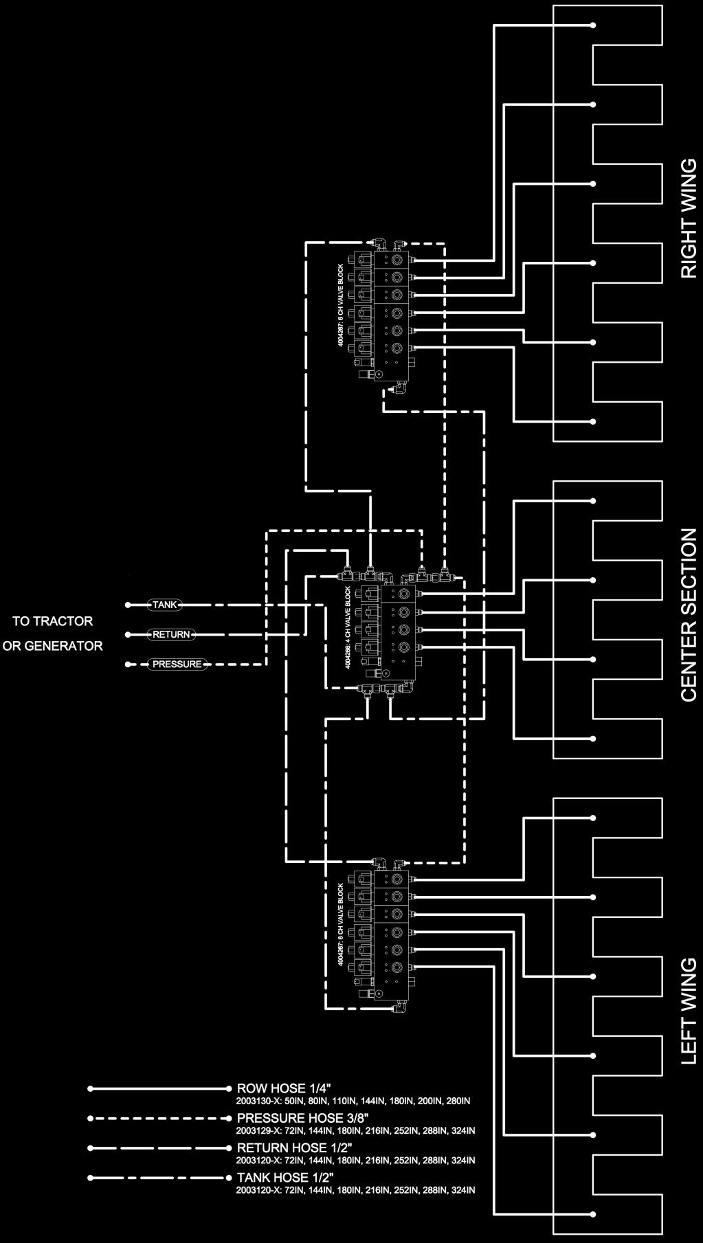
5 Installation Procedure Figure 1: Hose Length and Valve Block Placement 12 Row 16 Row 24 Row ROWS # Valve Block (# of Channels)

6 Installation Procedure: Table 1: Hose Length and Valve Block Size Valve Block 30 INCH ROW 12R 16R 24R # VB 5CH 2 # VB 6CH # VB 9CH 2 HOSES (IN) Refer to Figure 1 on page 5 for recommended valve block mounting locations. NOTE: Hoses have some extra length in some cases when valve blocks can not be mounted in the recommended locations. a. If mounting a valve block on center section, the cat walk support is a good option for mounting. 6

 7.")

7 Valve Solenoid Direction IMPORTANT: No matter how the valve block is mounted, it is imperative that the solenoid valves remain parallel to the ground! 6. Secure valve block to valve block bracket with 3/8 hardware. In some cases 4 bolts will be used but at least 3 bolts are required. (3 bolts and 8 section shown) 7. Next secure mounting bracket to a bar on planter. Slots allow for use with a 3 bar to 10 wide bar. The provided ½ carriage bolts can be used for a bar that is up to 12 deep. Use 2.75 carriage bolts for attaching to a plate with ½ holes up to 1 ½ inches thick (such as steps under central fill). 7


8 8. Mount assembly containing the valve block to mounting bracket that is installed on planter using carriage bolts and nylock nuts. NOTE: Additional mounting options are shown below. 9. Refer to Figure 1 on page 5 for hose routing. Attach the appropriate #4 hose to the actuator and route hoses to the appropriate valve block. 8

9 Figure 3: 2 Valve Blocks 9

10 Figure 4: 3 Valve Blocks 10

. Instructions provided in PCM kit. 13. Optional: If installing on a bulk-fill planter, install seed delivery pressure sensor.")
11 10. Connect the corresponding hose to the correct valve channel with a provided expander fitting. 90 degree fittings are provided if needed for cleaner routing of hoses. Expander Fitting 90º Fitting 11. Route Down Force Extension Cables from the correct RCM I/O connector to the corresponding connections on valve blocks. NOTE: Use the same method for cable selection as for hoses: Shorter cables to closer row units, Longer cables to farther row units. Down Force Cables Connections 12. Install PCM (Planter Control Module). Instructions provided in PCM kit. 13. Optional: If installing on a bulk-fill planter, install seed delivery pressure sensor. Instructions provided in bulk-fill pressure sensor kit. 11

12 14. Install an implement switch module on toolbar in front of each row unit that is equipped with an implement switch. NOTE: Module can be secured loosely for now until local CAN Bus is routed and ideal location is determined. 15. Connect CAN implement switch cable to implement switch module that was mounted on toolbar in previous step. 16. Connect integral cable of implement switch to mating connector of CAN implement switch cable. A 42 in. extension cable is provided if required. NOTE: Local CAN connectors of implement switch cable will be connected when local CAN Bus is installed in a following step. NOTE: The following steps detail how to properly install the Local CANBUS and power distribution cables. Refer to the line art drawing and table on the following two pages to aid in this process. NOTE: The line art on Figure 2 illustrates what the electrical components should look like. 12 rows are shown, but the same concept applies when there are more (or fewer) rows units. 12
13 Figure 2: Cable Routing Diagram 13
14 Table 2: Power Distribution Cables Front-Fold Planters (6 Rows Across the Rear when Folded) Cable P/N with Description 12R 16R 24R 36R RXR DF Only Power Extension Cable (P/N: ) RXR DF Only Power Extension Cable (P/N: ) 2 RXR DF Only Power Extension Cable (P/N: ) 2 RXR DF Only Power Extension Cable (P/N: ) 2 RXR DF Only Power Extension Cable (P/N: ) 2 RXR DF Only Power Extension Cable (P/N: ) 2 RXR DF Only Power Extension Cable (P/N: ) 2 P/N: Row Power Distribution 2 P/N: Row Power Distribution 2 P/N: Row Power Distribution P/N: Row Power Distribution 4 P/N: ga. Power Ext (CENTER SECTION) P/N: ga. Power Ext (WING SECTIONS CLOSEST TO CENTER) 2 P/N: ga. Power Ext (WING SECTIONS CLOSEST TO CENTER) 2 P/N: ga. Power Ext (WING SECTIONS CLOSEST TO CENTER) 2 P/N: ga. Power Ext (WING SECTIONS CLOSEST TO CENTER) 2 P/N: ga. Power Ext (OUTER WING SECTIONS) 2 P/N: ga. Power Ext (OUTER WING SECTIONS) 2 Narrow Front-Fold Planters (4 Rows Across the Rear when Folded) Cable P/N with Description 12R 16R 24R 36R RXR DF Only Power Extension Cable (P/N: ) RXR DF Only Power Extension Cable (P/N: ) 2 RXR DF Only Power Extension Cable (P/N: ) 2 2 RXR DF Only Power Extension Cable (P/N: ) 2 P/N: Row Power Distribution P/N: Row Power Distribution 2 2 P/N: ga. Power Ext (CENTER SECTION) P/N: ga. Power Ext (WING SECTIONS CLOSEST TO CENTER) 2 P/N: ga. Power Ext (WING SECTIONS CLOSEST TO CENTER) 2 2 P/N: ga. Power Ext (OUTER WING SECTIONS) 2 Front-Fold Interplant Planters Cable P/N with Description 12/23 12/24 16/31 16/32 RXR DF Only Power Extension Cable (P/N: ) 1 1 RXR DF Only Power Extension Cable (P/N: ) 2 2 RXR DF Only Power Extension Cable (P/N: ) 2 P/N: Row Power Distribution (Narrow Row / Interplant) 4 P/N: Row Power Distribution (Narrow Row / Interplant) 1 P/N: ga. Power Ext (CENTER SECTION) 1 P/N: ga. Power Ext (WING SECTIONS CLOSEST TO CENTER) 2 P/N: ga. Power Ext (WING SECTIONS CLOSEST TO CENTER) 2 14

15 17. Connect power extension cables as follows: Shortest extension is for center section connectors. Longer extensions are for outer wing connectors. See Table 1 on page 6 for additional clarification. NOTE: Power connectors on generator do not technically need to correspond to certain planter sections, but doing so is recommended for logical reasons. If SureDrive will be installed in addition to row by row down force, power extension cables will be a heavier gauge and look like the upper image. In that case, connect extension cables to generator. If installing row by row down force only (no SureDrive), power extension cables will look like the lower image. In that case, connect extension cables to high current power connectors of implement cable using provided power splitters. 18. Connect power distribution cables to extension cables installed in previous step. 19. Connect each drop of power distribution to mating connector of appropriate row unit RCM CAN stub. NOTE: Distribution cable shown is for 6 rows, but provided cables may have 4 or 8 drops, depending on planter configuration. 20. Connect terminating plug to mating connector of RCM CAN stub at leftmost row unit. It is important to use the correct terminator so the display will know that the left-most row unit is row #1. Terminator will connect to Local CAN left connector as illustrated on RCM CAN stub. NOTE: The RCM CAN stub at each row unit has a long and a short drop for the local CANBUS. The short drop should always be routed left and the longer drop to the right. This is very important to keep the row units indexed properly RCM CAN stub 15

16 21. Connect terminating receptacle to mating connector of RCM CAN stub at right-most row unit. Terminator will connect to Local CAN right connector as illustrated on RCM CAN stub in previous illustration. 22. Connect each row unit RCM CAN stub to its adjacent row unit CAN stubs. Always route longer end of RCM CAN stub toward the right. Connect PCM to local CANBUS at middle of toolbar using 9 ft CAN extensions. 2 ft CAN extensions are provided to go between row units at toolbar flex joints. 9 ft CAN extensions are provided to go around toolbar fold joints. See Figure 2 on page 13 and Table 2 on page 14 for additional clarification. 23. Install implement harness on planter frame near PCM and connect to PCM as follows: Power 1 connector of implement cable mates with ground receptacle of PCM I/O cable. ISOBUS plug of implement cable mates with receptacle of PCM ISOBUS breakout cable Install terminator (PCM kit) on remaining ISOBUS connector of PCM ISOBUS breakout cable. 16


17 24. Route opposite end of implement cable to tractor. Implement cable extensions are available if required. 25. Connect implement cable to IBBC connector of ISOBUS Power/Control assembly at rear of tractor. If an ISOBUS retrofit kit has not been installed, that must be done before this final step can be completed. Detailed installation instructions are provided in ISOBUS retrofit kit. 26. Bleeding the system: Pressurize the system to at least 1000 psi. Start at one side or the other. Attach a clear hose to the bleeder and run it into a oil catch pan or bucket. Open the bleeder with a wrench and close it when the oil runs free of air. Procede to the next row unit until all the air is out of the system. Post-Installation Checklist All cable ends and terminations are connected. All cables are secured with cable ties. Verify planter can fold and unfold without causing cable or hydraulic hose damage Verify CAN terminators are on correct ends of planter (see steps 13 & 14) 17
Wing-Fold Planters All Makes & Models
 Wing-Fold Planters All Makes & Models Row by Row Down Force Master Kit PN: 2006444-ENG REV. C Introduction Important Information This guide provides the basic information needed to install the Ag Leader
ISOBUS Down Force Hydraulics Kinze
 Important Notices Please carefully follow these step-by-step instructions. If you have questions, contact at 515-232-5363 x 1. Direction words (LEFT and RIGHT) are commonly used when describing an installation
Clutch Control. PN: November 2013 Rev E 1
 NOTE: Indented items indicate parts included in an assembly listed above Part Name/Description Part Number Quantity Module Kit 4100533 1 Cable Installation Kit 2000901-1 1 Alcohol swab packet 2002811 2
Ag Leader Technology InSight/Ag Leader Integra. OptRx OptRx Remote Sensor Kit
 : Indented items indicate parts included in an assembly listed above Part Name/Description Part Number Quantity Master Module Kit 4100804 1 Master Module 4001821 1 Cable - Master 4001904-10 1 Cable - CAN
DEERE-ORTHMAN DR SERIES PLANTERS
 DR PlanterS DEERE-ORTHMAN DR SERIES PLANTERS All-New Max Emerge TM 5 Row Units For real planting performance, follow the leader in stacking technology. With features like an improved doubles eliminator,
Planting. Press to Highlight Configuration. Gauge Wheel Load Alarm. Value must be entered for your specific planter and parallel arm combination
 To create a configuration, make the following button presses to start the Configuration Wizard and then follow the instructions given on the display. Planting Start of Configuration Wizard Enter Settings
MF 9520 / 9540 / 9560, Challenger 540C / 560C
 Ag Leader Combine Installation Note: Indented items indicate parts included in an assembly listed above Part Name/Description Part Number 9520 Quantity by Model 9540 540C Parts Kit 2001312-69 1 1 1 Drill
Instructions for 2-row monitoring only
 Installation Instructions for CaseIH cotton picker models: Instructions for 2-row monitoring only Ensure the model numbers shown above correspond to the machine model. If you receive the incorrect installation
Kinze 3000 Series Row Unit. Hydraulic Actuator Installation Instructions PN: ENG REV. A
 Kinze 3000 Series Row Unit Hydraulic Actuator PN: 2006428-ENG REV. A Installation Overview Required Parts Part Number Qty * Description 4003011 1 HYDRAULIC ACTUATOR ASSY. (INCLUDES MOUNTING HARDWARE) 4003458
PFadvantage JD 3300/4400/6600/7700; 4420
 Ag Leader Technology Combine Installation JD 33//66/77; 2 Note: Indented items indicate parts included Quantity by Model in an assembly listed above Early Late Part Name/Description Part Number 3 3 6 6
RAM Rail Mount Kit RAM 201UD 5 Arm RAM 2461U Base RAM 235U Base, Double U-Bolt
 Note: Indented items indicate parts included in an assembly listed above. Part Name/Description Part Number Quantity Direct Command Kit 4100514 1 Installation Instructions 2005690 1 CAN Y-Splice 4000137
Instructions for 2-row monitoring only
 Installation Instructions for CaseIH cotton picker models: Instructions for 2-row monitoring only CAUTION: Ensure the model numbers shown above correspond to the machine model. If you receive the incorrect
ADJUSTMENTS BEFORE GOING TO THE FIELD
 FIELD ADJUSTMENTS YIELD-PRO PLANTER with Air Pro Meters 2425A ADJUSTMENTS BEFORE GOING TO THE FIELD General Maintenance: 1). Refer to the operator s manual for proper lubrication intervals and maintenance
PN: A. Reactive Steering Kit Installation Manual
 PN: 602-0275-01-A Reactive Steering Kit Installation Manual LEGAL DISCLAIMER Note: Read and follow ALL instructions in this manual carefully before installing or operating the AutoSteer system. Note: Take
Assisted Steering Hydraulic Installation Manual for Vehicle Kit Number Fits Only AGCO Gleaner R62/R65 (after S/N 66000) and R72/R75 (after
 and R72/R75 (after") F i e l d p i l o t U s e r M A N U A L Assisted Steering Hydraulic Installation Manual for Vehicle Kit Number 91-02340 Fits Only AGCO Gleaner R62/R65 (after S/N 66000) and R72/R75 (after S/N 76000) Combines
F i e l d p i l o t U s e r M A N U A L Assisted Steering Hydraulic Installation Manual for Vehicle Kit Number 91-02340 Fits Only AGCO Gleaner R62/R65 (after S/N 66000) and R72/R75 (after S/N 76000) Combines
General Information. Notations and Conventions. Compatibility Check. Kit Description. Call-Outs. Part Lists Great Plains Manufacturing, Inc.
 Part Lists Great Plains Manufacturing, Inc. 1 Installation Instructions Loup Shaft Monitor Used with Drill models: Compatible with most 1995 and later, two- and three-box drills with 5 8 -inch square main
General Information. NOTE: Be sure you have the correct instructions for the monitor system you are using. Installation Instructions
 Installation Instructions 3-Section Folding No-Till Precision Seeding System Used with: 3N - 3010P & 3020P! When you see this symbol, the subsequent instructions and warnings are serious - follow without
2960 SERIES II UNIT MOUNTED CONSERVATION COULTER
 2960 SERIES II UNIT MOUNTED CONSERVATION COULTER YETTER MANUFACTURING CO. FOUNDED 1930 Colchester, IL 62326-0358 Toll free: 800/447-5777 309/776-3222 (Fax) Website: www.yetterco.com E-mail: info@yetterco.com
General Information. NOTE: Be sure you have the correct instructions for the monitor system you are using. Installation Instructions
 Installation Instructions 3-Section Folding No-Till Precision Seeding System Used with: 3N - 3010P & 3020P! When you see this symbol, the subsequent instructions and warnings are serious - follow without
INSTRUCTIONS 360 Y-DROP
 INSTRUCTIONS 60 Y-DROP INSTRUCTIONS 60 Y-DROP RECOMMENDED TOOLS Ratchet wrench with /" and 9/6" deep well sockets /8" -point socket /" and 9/6" combination wrenches Impact driver # Philips screwdriver
INSTRUCTIONS 360 Y-DROP
 INSTRUCTIONS 60 Y-DROP INSTRUCTIONS 60 Y-DROP INTRODUCTION Before beginning, it s important to know where each mounting bracket fits relative to the row spacing involved. The 60 Y-DROP unit should be precisely
Z48, Z54, ZSR54, ZSR60 ZXT54, ZXT60, ZT60, ZT72,
 Light Kit Assembly Instructions Z44 & Z2 w/s/n 472620+ Z48, Z4, ZSR4, ZSR60 ZXT4, ZXT60, ZT60, ZT72, ZT60i, ZT72i, ZT360, & ZT372 Manual No. 37-78M Before You Start! When you see this symbol, the subsequent
Seed-Squirter. Installation Guide. APPLICATION SYSTEMS FOR PROFESSIONALS. How Can We Help?
 Installation Guide APPLICATION SYSTEMS FOR PROFESSIONALS TM www.capstanag.com How Can We Help? 855-628-7722 prodsupport@capstanag.com P/N 115700-007 Rev. A Revised 02/2018 2018 Capstan Ag Systems, Inc.
GPS AutoSteer System Installation Manual
 GPS AutoSteer System Installation Manual John Deere MFWD Valve Install Vehicles Supported Models 7200 7210 7400 7410 7600 7510 7700 7610 7800 7710 7810 PN: 602-0212-01-A LEGAL DISCLAIMER Note: Read and
edrive VSi Installation Guide
 edrive VSi Installation Guide Kit: EDVSi-AGCO SWATHER, P/N 911-1001-000 Fits Challenger, Hesston and Massey Ferguson Swather Models: SP115B 8250 9260 * (see serial #) 9330 SP185B 8450 8250S 9340 9225 8550S
ADJUSTMENTS BEFORE GOING TO THE FIELD
 FIELD ADJUSTMENTS YIELD-PRO PLANTER 4010HDP, 4020P, 4025 3010HDP, 3020P, 3025 ADJUSTMENTS BEFORE GOING TO THE FIELD General Maintenance: 1). Refer to the operator s manual for proper lubrication intervals
INSTRUCTIONS 360 Y-DROP
 INSTRUCTIONS 60 Y-DROP 60 Y-DROP REGISTRATION Please visit productregistration.60yieldcenter.com to complete the product registration for your 60 Y-DROP so we can better support our products from day one
e -Stroke e-s 3 / GEN 3 Tractor / Truck / Bus Parts List
 e -Stroke e-s 3 / GEN 3 Tractor / Truck / Bus Parts List e-s 3 / GEN 3 Tractor / Truck / Bus CCMs Description Part # System Type Vehicle Type Axle No CCM 8291100 e-s 3 / GEN 3 Truck / Bus 2 CCM 8291101
Rostselmash Torum 740
 Note: Indented items indicate parts included in an assembly listed above Quantity by Model Part Name/Description Part Number 740 Combine Kit Torum 740 4100762 1 Threaded Arm Assembly 2000311-2 1 Header
INSTRUCTIONS 360 Y-DROP
 INSTRUCTIONS 60 Y-DROP 60 Y-DROP REGISTRATION Please visit productregistration.60yieldcenter.com to complete the product registration for your 60 Y-DROP so we can better support our products from day one
2-row and All-row systems included.
 Ag Leader Technology Cotton Picker Installation Installation Instructions for John Deere cotton picker models: 2-row and All-row systems included. IMPORTANT: Ensure the model numbers shown above correspond
ROW PRO DOWN PRESSURE
 Operator s Manual ROW PRO DOWN PRESSURE VERSION 2 & 3 Safety Notices... 1 Disclaimer... 1 Row-Pro Down Pressure... 3 Requirements... 3 Setup... 4 Control Mode... 4 Disable Down Pressure Modules... 7 Setting
SENTRY ISOBUS Tip Flow Monitor. Software Version 1.00
 SENTRY 6141 U S E R M A N U A L ISOBUS Tip Flow Monitor Software Version 1.00 Copyrights 2016 TeeJet Technologies. All rights reserved. No part of this document or the computer programs described in it
INSTALLATION MANUAL. Document revision: 1.3 Last revised: January 2, 2019
 INSTALLATION MANUAL Document revision: 1.3 Last revised: January 2, 2019 Recon SpreadSense Installation Manual 2017-19 Intelligent Agricultural Solutions. All Rights Reserved. Recon SpreadSense Installation
EARLY RISER 2160 LARGE FRONT FOLD PLANTER WITH OPTIONAL ROWTRAC CARRIER SYSTEM
 EARLY RISER 2160 LARGE FRONT FOLD PLANTER WITH OPTIONAL ROWTRAC CARRIER SYSTEM HIGH-EFFICIENCY PLANTING: COVER MORE GROUND IN LESS TIME. We rethought every inch of the new 2160 Early Riser planter to give
GPS AutoSteer System Installation Manual
 GPS AutoSteer System Installation Manual John Deere MFWD AutoTrac Ready Supported Models 8225R 8245R 8270R 8295R 8320R 8345R PN: 602-0254-01-A LEGAL DISCLAIMER Note: Read and follow ALL instructions in
Installation Guide _02 9/11 1
 Installation Guide 955168_02 9/11 1 Precision Planting, Inc. 23207 Townline Road Tremont, IL 61568 ph. (309) 925-5050 fax. (309) 925-5029 info@precisionplanting.com 2020support@precisionplanting.com Precision
WHSO3HD DirtWorks Installation Manual
 WHSO3HD DirtWorks 3-Point Hitch System Installation Manual Part Description Qty 1 Ø16 100 Pin 6 2 Actuator 1 3 R Pin 9 4 Pin C 2 5 Pin B 1 6 Lock Nut M16 2 7(A) Short Tow Bar For ATV 1 7(B) Long Bar For
Clutch Installation Case IH 1200 row unit
 Ag Leader Technology SeedCommand NOTE: Indented items indicate parts included in an assembly listed above Part Name/Description Part Number Quantity 4 row clutch installation kit Case IH 1200 Model year
Lexion 570R/575R, 580R/585R, 590R/595R
 Note: Indented items indicate parts included in an assembly listed above Quantity by Model 2006+ All Years Part Name/Description Part Number 570R 575R 580R 585R Instruction Kit Lexion 570/580/590 2005500-5
DODGE CUMMINS DUAL PUMP & DELUXE DUAL PUMP KIT
 SUBJECT: DODGE CUMMINS DUAL PUMP & DELUXE DUAL PUMP KIT Page 1 of 10 FITMENT: 2003 2007 Dodge Cummins with 5.9L KIT P/N: FPE-DPK-59-NP-[BK,BL,OG,RD], FPE-DPK-59-NP-DX [BK,BL,OG,RD], FPE-DPK-59-3K-[BK,BL,OG,RD],
Kit. Hydraulic Kit Installation Guide REV B Table 1 Component List. Item Component Part Number Qty
 Hydraulic Kit Installation Guide Table 1 Component List Item Component Part Number Qty 1. Hose 5/8 X 36-8F X -12F 90 DEG ORFS F451TC-JSJ9081210-36 2 2. HOSE ASSY. 1/4" X 36" -4F X -6F ORFS F451TC-JCJC040604-36
DRAGO. Corn Header Manual f HEADSIGHT.COM
 DRAGO Corn Header Manual 09020801f HEADSIGHT.COM 574.546.5022 About Headsight Headsight Contact Info Headsight, Inc. 4845 3B Road Bremen, IN 46506 Phone: 574-546-5022 Fax: 574-546-5760 Email: info@headsight.com
Installation Instructions ISOBUS Liquid ECU
 Installation Instructions ISOBUS Liquid ECU Liquid Fertilizer & Ammonia Display Screen Sprayer Display Screen Last Update: 3/1/2018 SW Version Liquid v.01.00.04.00 - ECU HW: 1.6-1.7 SW Version Liquid v.02.00.01.00
UTV Universal Stronghold Auto- Latch Double Boot Mount
 UTV Universal Stronghold Auto- Latch Double Boot Mount Product Instructions Part No: 0000 3 3 This Kit includes: Item Qty Part Description Bracket, Stronghold Adjustment Bracket, Bed Side Mount 3 Tube,
TWIN-ROW PLANTERS TWIN-ROW 825A3PM
 TWIN-ROW PLANTERS TWIN-ROW 4025A3PS TWIN-ROW 1225 & 1625AFF TWIN-ROW 825A3PM DOUBLE DOWN ON NEW TECHNOLOGY WITH CASE IH TWIN-ROW PLANTERS Farming is a gamble. But there are ways to cut your risk, improve
INSTALLATION INSTRUCTIONS
 INSTALLATION INSTRUCTIONS PERFORMANCE AT THE WHEELS KIT W125-42 GM 10 & 12 Bolt Rear Axles with Staggered or non-staggered Shocks with C-Clips Thank you for choosing STAINLESS STEEL BRAKES CORPORATION
INSTRUCTIONS 360 Y-DROP
 INSTRUCTIONS 60 Y-DROP JOHN DEERE 60 60 Y-DROP REGISTRATION Please visit productregistration.60yieldcenter.com to complete the product registration for your 60 Y-DROP so we can better support our products
Endeavor Fertilizer Controler" Electric Pump Fertilizer System for John Deere GS2 with Servo Control
 Endeavor Fertilizer Controler" Electric Pump Fertilizer System for John Deere GS with Servo Control We Can Also Interface with These Popular Third Party Controllers: Trimble - EZ Boom & Field IQ Ag Leader
Reference Manual /12
 DrillMaster Planter Drive Controller Reference Manual 612366-03/12 Table of Contents Description of Operation, Safety and Care.............. 1 Installation.................................... 2-3 Tractor
INSTRUCTIONS 360 Y-DROP
 INSTRUCTIONS 0 Y-DROP 0 Y-DROP REGISTRATION Please visit productregistration.0yieldcenter.com to complete the product registration for your 0 Y-DROP so we can better support our products from day one and
GMTRK1 BOLT-ON TRAIN HORN SYSTEM INSTALLATION INSTRUCTIONS. For GM & GMC Trucks & SUVS
 GMTRK1 BOLT-ON TRAIN HORN SYSTEM INSTALLATION INSTRUCTIONS For 2007-2017 GM & GMC Trucks & SUVS The GMTRK-1 System comes with a custom battery tray to hold the air compressor and air tank. The horns will
If there is additional labor or other costs above the 4 hrs labor you must call VMAC for approved coverage
 Installation Manual for the A500027 RAPTAIR MF Dual Air Filter Retrofit Kit Author: Brian Collings Date: 15/07/2014 1900997 - Manual, Installation (A500027) Systems or Parts Affected: D600005BETA01-D600005BETA59
INSTALLATION INSTRUCTIONS
 INSTALLATION INSTRUCTIONS REAR DISC BRAKE CONVERSION KIT A125-3 1965-72 GM A-BODY 10 & 12 BOLT AXLES Thank you for choosing STAINLESS STEEL BRAKES CORPORATION for your braking needs. Pleases take the time
General Information. Assembly Instructions. Before You Start. Marker Assembly. Assembly Instructions S and S Marker Option
 Great Plains Mfg., Inc. Assembly Instructions! Used with: 3000-3S 30 3-Section Folding Drill 2600-2S 26 2-Section Folding Drill Before You Start 3000-3S and 2600-2S Marker Option When you see this symbol,
Automated Steering Hydraulic Installation Kit
 Automated Steering Hydraulic Installation Kit P/N: ED-MF0 Fits Massey Ferguson Swather Models: 0 Read and Follow Safety Messages In these instructions, you will see the heading, WARNING, and the safety
General Information. Assembly Instructions. Point-Row Option 2004-
 3000-3S Used with: 3000-3S General Information! When you see this symbol, the subsequent instructions and warnings are serious - follow without exception. Your life and the lives of others depend on it!
INSTRUCTIONS 360 Y-DROP
 INSTRUCTIONS 60 Y-DROP 60 Y-DROP REGISTRATION Please visit productregistration.60yieldcenter.com to complete the product registration for your 60 Y-DROP so we can better support our products from day one
! CAUTION! ! WARNING!
 Assembly Instructions! 3N-3010P, No-Till Flat Fold Marker Option Used with: 3N-3010P Drills When you see this symbol, the subsequent instructions and warnings are serious - follow without exception. Your
INSTALLATION INSTRUCTIONS
 INSTALLATION INSTRUCTIONS REAR DISC BRAKE CONVERSION KIT A125-2 1955-70 FULL SIZE CHEVROLET Thank you for choosing STAINLESS STEEL BRAKES CORPORATION for your braking needs. Pleases take the time to read
ASSEMBLY MANUAL. 45-Foot Air Double Disc Drill. Amity Technology, LLC th Avenue North Fargo, ND (701)
") ASSEMBLY MANUAL 45-Foot Air Double Disc Drill Amity Technology, LLC 2800 7th Avenue North Fargo, ND 58102 (701) 232-4199 www.amitytech.com TABLE OF CONTENTS Main Frame 1 Wing Lock Towers 3 Wing Frames
ASSEMBLY MANUAL 45-Foot Air Double Disc Drill Amity Technology, LLC 2800 7th Avenue North Fargo, ND 58102 (701) 232-4199 www.amitytech.com TABLE OF CONTENTS Main Frame 1 Wing Lock Towers 3 Wing Frames
Quick Setup Guide for IntelliAg Model 3PYP 12 Row Single Row Air Pro
 STEP 1: Pre-Programming Preparation: Power on vehicle via ignition switch to activate Virtual Terminal (VT). Main menu will display pre-programmed default settings. If errors are detected (e.g., failed
INSTALLATION INSTRUCTIONS PERFORMANCE AT THE WHEELS KIT W125
 INSTALLATION INSTRUCTIONS PERFORMANCE AT THE WHEELS KIT W125 1968-81 CAMARO & FIREBIRD 10 & 12 BOLT W/"C" CLIPS Thank you for choosing STAINLESS STEEL BRAKES CORPORATION for your braking needs. Pleases
Full screen alarms identify abnormal or failed operation on all enabled system components/controls
 The world s most versatile controller IntelliAg puts the future of application control in your cab, providing state-of-the-art communication between implement and tractor. This precision farming system
Installation and Service Manual
 RESIDENTIAL PLATFORM LIFTS RPL400 / RPL600 Installation and Service Manual WARNING! STRICT ADHERENCE TO THESE INSTALLATION INSTRUCTIONS IS REQUIRED to promote the safety of those installing this product,
Pickup Truck Rack. Installation instructions for Ford - Chevy - Ram
 Installation instructions for Pickup Truck Rack Ford - Chevy - Ram MyGlassTruck.com 200 Acorn Road LOCAL 856-595-9069 WEB www.myglasstruck.com Glassboro, NJ 08028 FAX 856-863-1480 1-844-364-4022 Version
Installation Instructions
 Installation Instructions Accessories, Electric Trailer Brake Controller Ver 1.0 Page 1 of 9 August 2009 Accessory Development SUBJECT ELECTRIC TRAILER BRAKE CONTROLLER - P/N 82 11 0 420 082 MODEL X5 (E70):
Pitch Stop Mount Support for WRX/STI
 Pitch Stop Mount Support for 2015+ WRX/STI 2017-02-06 Thank you for purchasing this PERRIN product for your car! Installation of this product should only be performed by persons experienced with installation
Single-Sided Storage Rack Assembly Instructions
 Single-Sided Storage Rack Assembly Instructions H D I G J K M L F I D B C A E PART NAME QTY A. BASE BAR (50 ) 2 B. BASE BAR HULL GUARD (34 ) 2 C. BASE BAR END CAP 2 D. SAFETY END CAP 4 E. FOOT 4 F. UPRIGHT
! CAUTION! ! WARNING!
 Assembly Instructions! 24- and 30-Foot, No-Till Flat Fold Marker Option Used with: 2N-2410 and 2N-3010 Drills 2N-2420 and 2N-3020 Drills When you see this symbol, the subsequent instructions and warnings
GPS Steering System Installation Manual
 GPS Steering System Installation Manual Supported Vehicles Challenger Massey Ferguson AGCO MT-645C, MT-645D MF-8650 DT-205B MT-655C, MT-655D MF-8660 DT-225B MT-665C, MT-665D MF-8670 DT-250B MT-675C, MT-675D
Case IH 3320, 3330, and Booms AutoBoom Installation Manual. P/N Rev B 06/15
 Case IH 3320, 3330, and 4420-0120 Booms AutoBoom Installation Manual P/N 016-0230-091 Rev B 06/15 Copyright 2009 Disclaimer While every effort has been made to ensure the accuracy of this document, Raven
ROGATOR B RAVEN RS1 ISO GUIDANCE AND STEERING INSTALLATION GUIDE
 ROGATOR B RAVEN RS1 ISO GUIDANCE AND STEERING INSTALLATION GUIDE ROGATOR B RAVEN RS1 ISO GUIDANCE AND STEERING INSTALLATION GUIDE This quick guide provides the installation instructions for the RS1 on
Parts Manual HB40/25. Hipper Bedder. Copyright 2017 Printed 06/28/ P
 Table of Contents Parts Manual Hipper Bedder HB40/25 Read the Operator's manual entirely. When you see this symbol, the subsequent instructions and warnings are serious - follow without exception. Your
Quick Setup Guide for IntelliAg Model YP40 20 Air Pro
 STEP 1: Pre-Programming Preparation: The Quick Guide assumes the Virtual Terminal, Master Switch, Working Set Master, Working Set Member, and all sensors have been connected and properly installed. Reference
INSTALLATION INSTRUCTIONS
 INSTALLATION INSTRUCTIONS PERFORMANCE AT THE WHEELS KIT W155-5 CHRYSLER 8 3 /4" & 9 3 /4" REAR AXLES Thank you for choosing STAINLESS STEEL BRAKES CORPORATION for your braking needs. Please take the time
300 DDSS Harrows Flex Drag & Spiral Rollers
 300 DDSS Harrows Flex Drag & Spiral Rollers Kongskilde 300 DDSS Assembly Instructions and Operating Guide *Model may not be exactly as shown. Kongskilde reserves the right to make changes to product designs
HARD TRI-FOLD COVER SPECIAL BOLT ON SIDE RAIL INSTRUCTIONS 2016-ON TOYOTA TACOMA 5 BOX
 HARD TRI-FOLD COVER SPECIAL BOLT ON SIDE RAIL INSTRUCTIONS 2016-ON TOYOTA TACOMA 5 BOX Read and follow these special instructions along with the standard instructions carefully before installing or using
Detroit Speed, Inc. Detroit Speed C7 Rear Full Floater Kit P/N: , , , , &
 Detroit Speed, Inc. Detroit Speed C7 Rear Full Floater Kit P/N: 070512, 070607, 070616, 070626, 070636 & 070649 Thank you for purchasing the Detroit Speed Inc., C7 Rear Full Floater Kit. The Detroit Speed
IAG Street Series Air / Oil Separator (AOS) For 2017 WRX
 For 2017 WRX") P IAG Street Series Air / Oil Separator (AOS) For 2017 WRX Part# IAG-ENG-7152 Tools Required: Ratchet, torque wrench, extensions, needle nose pliers, hose cutter, snips/scissors, flathead screwdriver,
P IAG Street Series Air / Oil Separator (AOS) For 2017 WRX Part# IAG-ENG-7152 Tools Required: Ratchet, torque wrench, extensions, needle nose pliers, hose cutter, snips/scissors, flathead screwdriver,
IAG Street Series Air / Oil Separator (AOS) For WRX
 For WRX") P IAG Street Series Air / Oil Separator (AOS) For 2015-16 WRX Part# IAG-ENG-7152 Tools Required: Ratchet, torque wrench, extensions, needle nose pliers, hose cutter, snips/scissors, flat head screw driver,
P IAG Street Series Air / Oil Separator (AOS) For 2015-16 WRX Part# IAG-ENG-7152 Tools Required: Ratchet, torque wrench, extensions, needle nose pliers, hose cutter, snips/scissors, flat head screw driver,
FOLDING TOP HYDRAULIC CYLINDER HOSE IDENTIFICATION
 Page 1 of 50 Service Manual: POWER ROOF SYSTEM AND Print Date: CONVERTIBLE TOP FOLDING TOP HYDRAULIC CYLINDER HOSE IDENTIFICATION Fig 1: View Of Folding Top Hydraulic Cylinder 2006 Pontiac G6 3.9L Eng
Maximum Application Rates with Two 5.3 GPM Electric Pumps
 396-001450 Tower Electric Pump Fertilizer System and SureFire Commander II Maximum Application Rates with Two 5.3 GPM Electric Pumps Maximum Application Rates in GPA on 30" Rows at 6 MPH (no agitation)
Parts Manual FH6424HD, FH6630HD, FH6636HD, FH6642HD FH6845HD, FH6848HD & FH6851HD Series Harrow. Copyright 2016 Printed 04/03/ P
 Table of Contents Part Number Index Parts Manual 6000 Series Harrow FH6424HD, FH6630HD, FH6636HD, FH6642HD FH6845HD, FH6848HD & FH6851HD Read the Operator's manual entirely. When you see this symbol, the
Product Name Chair Conversion Kit (to Console Delivery Unit) Installation [Kit # xx]
![Product Name Chair Conversion Kit (to Console Delivery Unit) Installation [Kit # xx]](/thumbs/85/92245042.jpg "Product Name Chair Conversion Kit (to Console Delivery Unit) Installation [Kit # xx]") Elevance Product Name Chair Conversion Kit (to Console Delivery Installation Unit) Installation [Kit #002-1965-xx] Attention: Use this kit to convert an Elevance Chair to a Chair with an Elevance Console
Elevance Product Name Chair Conversion Kit (to Console Delivery Installation Unit) Installation [Kit #002-1965-xx] Attention: Use this kit to convert an Elevance Chair to a Chair with an Elevance Console
Window Freezing, Losing Initialization
 S-SB-0001-14 January 9, 2014 Service Category Vehicle Exterior Section Window/Glass Market USA Applicability YEAR(S) MODEL(S) ADDITIONAL INFORMATION 2013 FR-S Introduction Some 2013 model year Scion FR-S
PS SERIES PNEUMATIC SEEDERS UNRIVALED PRECISION GLOBALLY ACCLAIMED PNEUMATIC SEEDERS TO COMPLIMENT ANY TASK
 PS SERIES PNEUMATIC SEEDERS UNRIVALED PRECISION GLOBALLY ACCLAIMED PNEUMATIC SEEDERS TO COMPLIMENT ANY TASK Item Number 00210-3-268, Version 1.1 EN US PS SERIES PNEUMATIC SEEDERS APV PNEUMATIC SEEDER OPERATIONS
Part Number Part Name/Description Instruction Kit JD 9x50/9x60/9x Flow Sensor
 ATTENTION If installing combine kit on a 9x70 series combine with factory-installed yield/moisture sensors, please take note of the special instructions in the Operational Checkout section (page 41) for
Instructions for Micro-Trak Seed Rate Control Systems Used with AgLeader INSIGHT, INTEGRA One, Two and Three Section
 1. Use AgLeader System Diagrams and Operator Manual to install system components and harnessing. 2. Connect Hydraulic Seed Control Module to the planter drives (as shown below) using Micro-Trak P/N 18030
For Cummins 404, 404B, 404BG, & 404C
 Parts Manual For Cummins 404, 404B, 404BG, & 404C The Model 404 Jake Brake retarder is designed and approved for use on Cummins L10 engines including 49 state, Carb (Calif.) and 88L10 engines. The Model
Sprayer Control. Manual for SprayLink Cable Installations. Tank. Jet Agitator. Agitator Valve. Diaphragm Pump. Pressure Transducer.
 Sprayer Control Plumbing & Installation Manual for SprayLink Cable Installations Tank Jet Tank Shut-Off Diaphragm Pump Electric Ball s Transducer Strainer Relief Regulating Copyrights 2012 TeeJet Technologies.
Part Name/Description Part Number Quantity Instruction Kit Metalfor Flow Sensor
 NOTE: Indented items indicate parts included in an assembly listed above Part Name/Description Part Number Quantity Instruction Kit Metalfor 4101091 1 Flow Sensor 4001356 1 Deflector plate 2000612-1 1
GPS AutoSteer System Installation Manual
 GPS AutoSteer System Installation Manual Supported Vehicles Case IH Vehicles Case 2577 Combines Case 2588 Combines Accuguide Ready PN: 602-0233-01-A LEGAL DISCLAIMER Note: Read and follow ALL instructions
KPM III ELECTRONIC SEED MONITOR INSTALLATION INSTRUCTIONS
 KPM III ELECTRONIC SEED MONITOR INSTALLATION INSTRUCTIONS Rev. 9/07 Throughout these instructions the symbol and/or the words NOTE, IMPORTANT, CAUTION, WARNING or DANGER are used to call your attention
INSTALLATION INSTRUCTIONS
 INSTALLATION INSTRUCTIONS REAR DISC BRAKE CONVERSION KIT A126-1 1973-87 CHEVROLET 1/2 TON 2WD Thank you for choosing STAINLESS STEEL BRAKES CORPORATION for your braking needs. Pleases take the time to
Installation Guide CLAAS Lexion Combines with 9 inch Elevators
 Installation Guide CLAAS Lexion Combines with 9 inch Elevators 955614_01 4/17 1 Table of Contents System Overview 3 Quick Start Guide 4 Flow Sensor Installation 5 Hydraulic Elevator Adjustment Kit Installation
WINCH MOUNT KIT FOR POLARIS RANGER P/N ASSEMBLY / OWNERS MANUAL. Application WINCH KIT NO. 25-9xxx
 WINCH MOUNT KIT FOR POLARIS RANGER P/N 25-3300 ASSEMBLY / OWNERS MANUAL Application WINCH KIT NO. 25-9xxx Before you begin, please read these instructions and check to be sure all parts and tools are accounted
Do not print this page
 Do not print this page 2006. Nautilus, Inc. All Rights Reserved. Schwinn is a registered trademark. Nautilus, Inc., World Headquarters, 16400 SE Nautilus Dr., Vancouver, WA 98683 Recumbent Assembly guide
Pull-Type Digger-Inverters
 Pull-Type Digger-Inverters ADI-836PT, 838PT, 840PT, ADI-1236PT Addendum MAN138 Read this manual before using this product. Failure to follow the instructions and safety precautions in this manual can result
Ford 6.7 EGR Delete Kit
 Fits: 2011 12 Powerstroke 6.7L Read instructions thoroughly before proceeding! ***This kit may void factory warranty please check with manufacturer.*** ***This kit is intended for off road use only.***